EP0909577B1 - Mobile Anlage zum Reinigen kontaminierter Luft - Google Patents
Mobile Anlage zum Reinigen kontaminierter Luft Download PDFInfo
- Publication number
- EP0909577B1 EP0909577B1 EP98119267A EP98119267A EP0909577B1 EP 0909577 B1 EP0909577 B1 EP 0909577B1 EP 98119267 A EP98119267 A EP 98119267A EP 98119267 A EP98119267 A EP 98119267A EP 0909577 B1 EP0909577 B1 EP 0909577B1
- Authority
- EP
- European Patent Office
- Prior art keywords
- filter
- unit
- installation according
- air
- activated carbon
- Prior art date
- Legal status (The legal status is an assumption and is not a legal conclusion. Google has not performed a legal analysis and makes no representation as to the accuracy of the status listed.)
- Expired - Lifetime
Links
Images
Classifications
-
- B—PERFORMING OPERATIONS; TRANSPORTING
- B01—PHYSICAL OR CHEMICAL PROCESSES OR APPARATUS IN GENERAL
- B01D—SEPARATION
- B01D53/00—Separation of gases or vapours; Recovering vapours of volatile solvents from gases; Chemical or biological purification of waste gases, e.g. engine exhaust gases, smoke, fumes, flue gases, aerosols
- B01D53/02—Separation of gases or vapours; Recovering vapours of volatile solvents from gases; Chemical or biological purification of waste gases, e.g. engine exhaust gases, smoke, fumes, flue gases, aerosols by adsorption, e.g. preparative gas chromatography
- B01D53/04—Separation of gases or vapours; Recovering vapours of volatile solvents from gases; Chemical or biological purification of waste gases, e.g. engine exhaust gases, smoke, fumes, flue gases, aerosols by adsorption, e.g. preparative gas chromatography with stationary adsorbents
- B01D53/0407—Constructional details of adsorbing systems
-
- B—PERFORMING OPERATIONS; TRANSPORTING
- B01—PHYSICAL OR CHEMICAL PROCESSES OR APPARATUS IN GENERAL
- B01D—SEPARATION
- B01D2253/00—Adsorbents used in seperation treatment of gases and vapours
- B01D2253/10—Inorganic adsorbents
- B01D2253/102—Carbon
-
- B—PERFORMING OPERATIONS; TRANSPORTING
- B01—PHYSICAL OR CHEMICAL PROCESSES OR APPARATUS IN GENERAL
- B01D—SEPARATION
- B01D2259/00—Type of treatment
- B01D2259/45—Gas separation or purification devices adapted for specific applications
- B01D2259/455—Gas separation or purification devices adapted for specific applications for transportable use
-
- B—PERFORMING OPERATIONS; TRANSPORTING
- B01—PHYSICAL OR CHEMICAL PROCESSES OR APPARATUS IN GENERAL
- B01D—SEPARATION
- B01D53/00—Separation of gases or vapours; Recovering vapours of volatile solvents from gases; Chemical or biological purification of waste gases, e.g. engine exhaust gases, smoke, fumes, flue gases, aerosols
- B01D53/02—Separation of gases or vapours; Recovering vapours of volatile solvents from gases; Chemical or biological purification of waste gases, e.g. engine exhaust gases, smoke, fumes, flue gases, aerosols by adsorption, e.g. preparative gas chromatography
- B01D53/04—Separation of gases or vapours; Recovering vapours of volatile solvents from gases; Chemical or biological purification of waste gases, e.g. engine exhaust gases, smoke, fumes, flue gases, aerosols by adsorption, e.g. preparative gas chromatography with stationary adsorbents
- B01D53/0407—Constructional details of adsorbing systems
- B01D53/0446—Means for feeding or distributing gases
Definitions
- the invention relates to a mobile system for cleaning contaminated air according to the preamble of claim 1.
- Such systems are mainly used in localized areas Areas such as Landfills, contaminated sites, composter plants, manufacturing plants etc., where there are pollutant emissions as a result of the work processes there. Outgassing, soil and air movements etc. contaminants get into gas and Particle form from the underground into the air and are there by the in people working in this area are inhaled.
- One system provides that the vehicle operator has a respirator and possibly wearing a protective suit.
- this is a significant one Reduced comfort for the driver, which in some cases means that the respirators are not worn.
- Furthermore are subject to respiratory masks and protective suits, so that Continuous operation is difficult to maintain for long periods can be preserved.
- a mobile filter system is known from FR 2 653 354 A1 a filter and a blower unit.
- the filter unit consists of several filter elements arranged in a ring.
- the blower unit is at the front end of the filter system in its longitudinal axis arranged and causes a flow through the system, in which the to be cleaned Air penetrates radially over the lateral surface into the filter unit and in the axial Direction emerges from the filter system. There is a reversal of the flow also mentioned. Due to the special arrangement of the blower unit at least partially in the axial cavity of the filter unit is said to be a special one easy to handle mobile filter system.
- the filter unit in known systems is usually designed so that the contaminated air first flows through a coarse and then a fine dust filter and is cleaned of solid particles. Only then does the air flow through an activated carbon filter that eliminates the remaining pollutants; the activated carbon filter is the last filter element in the flow direction.
- the invention has for its object a system specify that allows a compact and therefore manageable design without thereby losses in terms of filter service life, filter performance or To have to accept maintenance expenses.
- this object is achieved by a system with the features of claim 1 solved.
- the basic idea of the invention is to close the plant optimize that both coarse and fine dust filters, as well as activated carbon filters have the same service life. This is done by changing the flow direction is reversed by the filter, i.e. the filter in an inventive The system is started radially from the longitudinal axis of the filter in the direction of the lateral surface flows through. This entails that the activated carbon filter, which, as described, as flow through the last filter element in the area of the lateral surface is arranged.
- Another advantage of this system is that all filter elements together by a single clamping device, e.g. on the housing cover, between the sealing surfaces of the front and rear filter faces can be clamped.
- Another advantage is that all filter elements are consumed at about the same time and are therefore changed at the same time. With that the The effort to change the filter is kept to a minimum.
- the filter unit consists of several nested cylindrical filter elements.
- the filter elements are precisely matched to one another Construction additionally supported.
- Each of the elements can have one contain different filters, so that the filter unit with greatest possible flexibility to the different pollutant emissions of the respective locations can be adapted.
- a Radon filter This can be done both in the filter unit itself and in the Blower unit can be arranged.
- the filter unit with a Ionization tube can be combined, which is also a sterilizing and Part has a pollutant-reducing effect.
- Such an ionization tube can be used for Example in the area of the longitudinal filter axis or in the blower unit be arranged.
- the filter unit can be used to separate solid particles also a cyclone upstream.
- Dust filter it is possible to have larger ones Dust filter to be used instead of the activated carbon filter when the activated carbon filter is not required and it is only contaminated particles.
- the fine dust filters are as Teflon-coated membrane filter. These can be cleaned if necessary and therefore can be used again and again. They are also able to Retain aerosol bacteria and the finest smoke particles.
- blower unit has a brushless one Disc motor has. This will cause abrasion of carbon brushes like this is avoided with conventional DC motors. With help of a such powerful blower drive, it is possible to apply high pressure build up so that even with higher pollution still reasonable Service life of the filter elements can be achieved.
- Teflon-coated membrane filters even set such a powerful one Blower ahead.
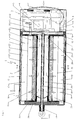
- the blower unit 3 consists essentially of a disc motor 5, which drives a blower 6. This causes ambient air to flow through the face Perforated plate 7 sucked into the blower 6 and pressed into the air duct 8.
- the Airflow is symbolized by arrows.
- the air duct 8 is from Housing 4 and a sheet 9 formed and leads to an air distribution chamber 10, which is limited by the partition plates 11 and 12. In the area around the The longitudinal axis of the filter is 12 through openings 14 in the partition plate arranged. These allow the air flow to enter the filter unit 2 Attachment 1.
- the filter unit 2 essentially consists of the coarse dust filter element 15, the fine dust filter element 16 and the activated carbon filter element 17 and one Closing device, consisting of a threaded rod 18, a wing nut 19 and a housing cover 28.
- the coarse dust filter element 15 has a hollow cylindrical shape circular cross section. It is centered on the filter longitudinal axis 13 in the Filter unit 2 arranged.
- a centering aid serves as a centering aid Subdivision plate 12 connected end cap 20.
- a fine dust filter element 16 is arranged around the coarse dust filter element 15. It also has an annular cross section, the inside diameter of the Fine dust filter element 16 is slightly larger than the outer diameter of the Coarse dust filter element 15. Further towards housing 4 closes in the same An activated carbon filter element 17 on the fine dust filter element 16.
- the Activated carbon filter element 17 is divided by a perforated plate 23, so that two hollow cylindrical filter chambers 24 and 25 within the filter element 17 result. Chambers 24 and 25 correspond to pollutant emissions filled with various types of activated carbon.
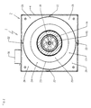
- the dimensions of the housing 4 and the outer diameter of the Activated carbon filter elements 17 are coordinated so that a certain clearance is kept at the narrowest point. So that Activated carbon filter element 17 is nevertheless held centrally in the filter unit 2, are four web plates 22 in this area to support the Activated carbon filter element 17 arranged (Fig. 2).
- the housing 4 Since the filter elements 15, 16 and 17 have an annular cross section, the housing 4 but has a square cross section, the housing 4 Web plates 22 and the activated carbon filter element 17 air channels 26 in the direction of Longitudinal filter axis 13 formed. Recesses 27 in the web plates 22 enable an air exchange between the individual air channels 26.
- All filter elements 15, 16 and 17 can be independently in the Slide filter unit 2. This provides the greatest possible flexibility in the combination the various filter elements possible.
- a removable one Housing cover 28 arranged at the front free end of the filter unit 2 .
- it serves to fix the filter elements 15, 16 and 17, on the other hand, it ensures an airtight seal of the housing 4.
- the housing cover 28 is held by using a kind of wing nut 19, which can be screwed onto the threaded rod 18, pressed against the housing 4 becomes.
- the additional equipment in system 1 also includes sensors 31 and 32. These are attached to the partition plate 11 and reach with one End in the filter unit 2.
- the sensors 31 and 32 check the presence of Filter elements and give an alarm if a filter element should be missing.
- the air flow After the air flow is guided into the filter unit 2, it can pass through there the coarse dust filter 15 formed cylindrical cavity 29 in the direction of Flow longitudinal filter axis 13. As a result of the overpressure caused by the Blower unit 3 is generated in the cavity 29, the air penetrates the individual filter elements 15, 16 and 17 in succession in the radial direction. there larger, then finer solid particles are retained until finally in the activated carbon filter element 17 gaseous pollutants are eliminated.
- an air hose (not shown) is arranged, which contains the cleaned air into the driver's cabin of a vehicle.
- the embodiment described above relates to a filter in which the air to be cleaned is pushed through the filter. But it is also possible that suck air to be cleaned through the filter. The prerequisite for this is the Generation of a negative pressure in the channels 26, for which the invention System needs to be changed slightly.
- the housing cover 28 on the front side of the filter unit 2 becomes permeable to air formed, the end face of the blower unit 3, however, with the elimination of Perforated sheet 7 impermeable to air. Furthermore, there are only between Blower unit 3 and filter unit 2 passages from the channels 26 to the Blower unit suction area 3. A direct connection between Blower unit 3 and cavity 29 are therefore no longer available.
- the cleaned air is directly from the blower 6 of the driver's cabin of the vehicle fed.
Description
- Fig. 1
- einen Längsschnitt durch eine Anlage entlang der in Fig. 2 dargestellten Linie I-I und
- Fig. 2
- einen Querschnitt der in Fig. 1 dargestellten Anlage entlang der Linie II-II.
Claims (9)
- Mobile Anlage zum Reinigen kontaminierter Luft mit einer Gebläseeinheit, einer Filtereinheit sowie Zu- und Abluftleitungen, wobei die Gebläseeinheit Umgebungsluft ansaugt, zur Reinigung durch den Filter führt und schließlich gereinigt aus der Anlage herausführt, dadurch gekennzeichnet, daß die Filtereinheit (2) aus mindestens einem zylinderförmigen Filterelement (15, 16, 17) besteht, bei dem an der Außenseite des Zylindermantels ein Aktivkohlefilter (17) und an der Innenseite des Zylindermantels ein Feststofffilter (15, 16) angeordnet ist und die Gebläseeinheit (3) von einem bürstenlosen Scheibenläufermotor (5) angetrieben ist.
- Anlage nach Anspruch 1, dadurch gekennzeichnet, daß die Filtereinheit (2) aus mehreren zylinderförmigen Filterelementen (15, 16, 17) besteht, die ineinander verschieblich angeordnet sind.
- Anlage nach Anspruch 1 oder 2, dadurch gekennzeichnet, daß der Aktivkohlefilter zweigeteilt ist und mindestens zwei Filterelemente aufweist.
- Anlage nach einem der Ansprüche 1 bis 3, dadurch gekennzeichnet, daß der Feststofffilter aus einem Grobstaubfilter (15) und/oder Feinstaubfilter (16) besteht.
- Anlage nach Anspruch 4, dadurch gekennzeichnet, daß der Feinstaubfilter (16) als teflonbeschichteter Membranfilter ausgebildet ist.
- Anlage nach einem der Ansprüche 1 bis 5, dadurch gekennzeichnet, daß die Filtereinheit (2) einen Radonfilter aufweist.
- Anlage nach einem der Ansprüche 1 bis 6, dadurch gekennzeichnet, daß der Filtereinheit (2) ein Zyklon vorgeschaltet ist.
- Anlage nach einem der Ansprüche 1 bis 7, dadurch gekennzeichnet, daß die Filtereinheit (2) mit einer lonisationsröhre kombiniert ist.
- Anlage nach einem der Ansprüche 1 bis 8, dadurch gekennzeichnet, daß die Filterelemente (15, 16, 17) mit einem elektronischen Chip versehen sind, der abgelesen und beschrieben werden kann.
Applications Claiming Priority (2)
| Application Number | Priority Date | Filing Date | Title |
|---|---|---|---|
| DE29718284U | 1997-10-15 | ||
| DE29718284U DE29718284U1 (de) | 1997-10-15 | 1997-10-15 | Mobile Anlage zum Reinigen kontaminierter Luft |
Publications (3)
| Publication Number | Publication Date |
|---|---|
| EP0909577A2 EP0909577A2 (de) | 1999-04-21 |
| EP0909577A3 EP0909577A3 (de) | 1999-11-17 |
| EP0909577B1 true EP0909577B1 (de) | 2003-04-02 |
Family
ID=8047260
Family Applications (1)
| Application Number | Title | Priority Date | Filing Date |
|---|---|---|---|
| EP98119267A Expired - Lifetime EP0909577B1 (de) | 1997-10-15 | 1998-10-13 | Mobile Anlage zum Reinigen kontaminierter Luft |
Country Status (3)
| Country | Link |
|---|---|
| US (1) | US6179903B1 (de) |
| EP (1) | EP0909577B1 (de) |
| DE (2) | DE29718284U1 (de) |
Families Citing this family (17)
| Publication number | Priority date | Publication date | Assignee | Title |
|---|---|---|---|---|
| US6558444B1 (en) * | 1998-12-03 | 2003-05-06 | Psi Global Ltd. | Fluid filters having a concealed machine-readable identification |
| FR2799389B1 (fr) * | 1999-10-12 | 2001-12-07 | Sofrance Sa | Procede et dispositif de traitement de vapeurs emises lors du pompage de liquides renfermant des composes volatils au cours d'operations de nettoyage ou de remplissage. |
| AU1949700A (en) * | 2000-02-25 | 2001-08-30 | Joy Mm Delaware, Inc. | Dust collection system for a bolting machine |
| SE0100238L (sv) * | 2001-01-29 | 2002-07-30 | Haldex Brake Prod Ab | Modulär lufttillförsel |
| FR2837112B1 (fr) * | 2002-03-12 | 2009-07-31 | Joel Maurice Henri Gonthier | Principe d'un systeme de filtration en cascade avec pompe d'extraction integree avec chambre d'absorption |
| US7115155B2 (en) * | 2002-12-06 | 2006-10-03 | Ronald Donald Stead | Air filtration apparatus and aromatizer |
| US6824596B2 (en) * | 2003-02-19 | 2004-11-30 | Jan Strmen | Gas scrubbing device for odorizing equipment operation, service and emergency |
| US6962621B2 (en) * | 2003-07-17 | 2005-11-08 | Jae-Hak Jung | System for simultaneously removing dust and volatile toxic organic compounds |
| US7048773B2 (en) * | 2003-08-04 | 2006-05-23 | Riedel Steve D | Universal vacuum filter cartridge |
| AU2003282170A1 (en) * | 2003-09-17 | 2005-04-11 | Joel Gonthier | Cascading filtration system having an integrated extraction pump with an absorption chamber |
| AU2004325957A1 (en) * | 2004-12-20 | 2006-06-29 | Ronald D. Stead | Air filtration apparatus and aromatizer |
| CN101198394B (zh) * | 2005-04-18 | 2012-05-23 | 新东工业株式会社 | 具有除臭功能设有除臭过滤设备的烟雾粉尘收集器 |
| US7686871B2 (en) * | 2006-05-02 | 2010-03-30 | Seagate Technology Llc | Integrated filter assembly |
| WO2012030810A1 (en) * | 2010-09-01 | 2012-03-08 | Battelle Memorial Institute | Recirculating air-filtration unit |
| CN109999578A (zh) * | 2019-04-09 | 2019-07-12 | 上海先越冶金技术股份有限公司 | 一种新型的过滤工业清洗机废气的移动式过滤器 |
| CN111715026A (zh) * | 2020-06-20 | 2020-09-29 | 安徽宝图实验室设备有限公司 | 一种具有延时机制的过滤箱 |
| US11123678B2 (en) | 2021-05-04 | 2021-09-21 | GPL Odorizers LLC | Air filtration device |
Family Cites Families (21)
| Publication number | Priority date | Publication date | Assignee | Title |
|---|---|---|---|---|
| US3308610A (en) * | 1964-03-31 | 1967-03-14 | Robbins & Myers | Fluid apparatus for removing mist or vapors from the air |
| SE419509B (sv) * | 1976-08-10 | 1981-08-10 | Wennberg Flex Ake Ab | For rening av luft i arbetslokaler o dyl avsedd anordning |
| US4210429A (en) * | 1977-04-04 | 1980-07-01 | Alpine Roomaire Systems, Inc. | Air purifier |
| SE415528B (sv) * | 1978-04-10 | 1980-10-13 | Dustcontrol Ab | Stoftavskiljare av cyklontyp, med kontinuerlig rensning av ett i apparaten fritt inskjutande finfilter |
| SU874129A1 (ru) * | 1978-08-16 | 1981-10-23 | Ордена Трудового Красного Знамени Экспериментальный Научно-Исследовательский Институт Металлорежущих Станков | Устройство дл отсоса и очистки воздуха |
| US4339250A (en) * | 1980-07-17 | 1982-07-13 | Thut Timothy T | Fresh air fountain air filter arrangement |
| US4377399A (en) * | 1981-02-06 | 1983-03-22 | Vaportek, Inc. | Air freshening device |
| US4477270A (en) * | 1983-01-07 | 1984-10-16 | Franz Tauch | Air filter |
| CH661785A5 (de) * | 1984-02-07 | 1987-08-14 | Plaston Ag | Luftreinigungsgeraet. |
| GB2164870B (en) * | 1984-10-02 | 1988-06-29 | Marshall D A G | Fluid filter |
| US4701195A (en) * | 1986-07-03 | 1987-10-20 | Amway Corporation | Room air treatment system |
| US4737173A (en) * | 1986-07-03 | 1988-04-12 | Amway Corporation | Room air treatment system |
| US4838903A (en) * | 1987-05-20 | 1989-06-13 | Ceco Filters, Inc. | Multi-phase thick-bed filter |
| FR2653354B1 (fr) | 1989-10-25 | 1992-09-04 | Poelman Sofiltra | Equipement de filtration autonome et portable. |
| US5120331A (en) * | 1990-02-06 | 1992-06-09 | Keith Landy | Composite gas filtering unit |
| US5240478A (en) * | 1992-06-26 | 1993-08-31 | Messina Gary D | Self-contained, portable room air treatment apparatus and method therefore |
| US5399319A (en) * | 1993-08-02 | 1995-03-21 | Vector Technologies Ltd. | Apparatus for filtering air and for creating a positive/negative pressure |
| CA2130584C (en) * | 1993-08-23 | 1999-12-07 | Bernard Chiu | Filter air cleaner |
| DE4421911C2 (de) | 1994-06-24 | 1997-04-30 | Friatec Keramik Kunststoff | Gasfilfer |
| US5641343A (en) * | 1996-01-25 | 1997-06-24 | Hmi Industries, Inc. | Room air cleaner |
| US5803940A (en) * | 1996-06-11 | 1998-09-08 | Amway Corporation | Air treatment system |
-
1997
- 1997-10-15 DE DE29718284U patent/DE29718284U1/de not_active Expired - Lifetime
-
1998
- 1998-10-08 US US09/168,504 patent/US6179903B1/en not_active Expired - Lifetime
- 1998-10-13 DE DE59807710T patent/DE59807710D1/de not_active Expired - Lifetime
- 1998-10-13 EP EP98119267A patent/EP0909577B1/de not_active Expired - Lifetime
Also Published As
| Publication number | Publication date |
|---|---|
| US6179903B1 (en) | 2001-01-30 |
| DE59807710D1 (de) | 2003-05-08 |
| EP0909577A3 (de) | 1999-11-17 |
| EP0909577A2 (de) | 1999-04-21 |
| DE29718284U1 (de) | 1997-12-11 |
Similar Documents
| Publication | Publication Date | Title |
|---|---|---|
| EP0909577B1 (de) | Mobile Anlage zum Reinigen kontaminierter Luft | |
| EP0050243B1 (de) | Verfahren und Vorrichtung zur Reinigung von mit Schadstoffen belasteter Luft | |
| EP0211383B1 (de) | Filtergerät | |
| DE3404395C2 (de) | ||
| EP3062909B1 (de) | Filterwechselvorrichtung und verfahren zu deren betrieb | |
| EP2500491B1 (de) | Personenschutzsystem | |
| DE102017001372A1 (de) | Verfahren zur Filtration von mit Partikeln belasteten Gasen sowie Filtervorrichtung zur Durchführung eines solchen Verfahrens | |
| DE102016001486B4 (de) | Vorrichtung zum Filtrieren von verunreinigter Luft und Filtermodul zur Verwendung in einer solchen Vorrichtung | |
| DE2540141A1 (de) | Filteranlage zum reinigen von gas- oder luftstroemen | |
| EP0594216B1 (de) | Filtergerät für ein gasförmiges Medium | |
| DE102019127751A1 (de) | Filtervorrichtung und Verfahren zum Abreinigen eines Filterelements einer Filtervorrichtung | |
| DE102021129671A1 (de) | Filtermodul, Anlage zur Filterung von Stäuben und Verfahren zur Abtrennung von Stäuben aus einem Gasstrom | |
| WO2022117730A1 (de) | Luftreinigungseinrichtung und luftreinigungssystem sowie verfahren zur reinigung einer luftreinigungseinrichtung und eines luftreinigungssystems | |
| DE19646504C2 (de) | Führerkabine für eine Arbeitsmaschine | |
| DE3802356A1 (de) | Klimasystem fuer arbeits- und transportfahrzeuge | |
| DE2212687A1 (de) | Belueftungseinrichtung fuer den innenraum von fahrzeugen | |
| DE102020121872A1 (de) | Fahrzeuginnenraum-Luftreinigungssystem | |
| DE102020106011A1 (de) | Mobile Absauganlage | |
| DE4421911C2 (de) | Gasfilfer | |
| DE19858883A1 (de) | Verfahren und Vorrichtung zur Entstaubung von Räumen mit hoher Staubbelastung | |
| CH691432A5 (de) | Luftreinigungsgerät. | |
| DE102006009965B4 (de) | Absaug-Anlage für eine spanabhebende Bearbeitungs-Maschine | |
| DE4435739A1 (de) | Einrichtung zur periodischen Abreinigung von Luftfiltern | |
| DD156517B1 (de) | Einrichtung zur reinigung von luft | |
| EP1861270A1 (de) | Grobstaubvorabscheider für kraftfahrzeugklimaanlagen |
Legal Events
| Date | Code | Title | Description |
|---|---|---|---|
| PUAI | Public reference made under article 153(3) epc to a published international application that has entered the european phase |
Free format text: ORIGINAL CODE: 0009012 |
|
| AK | Designated contracting states |
Kind code of ref document: A2 Designated state(s): DE FR IT NL |
|
| AX | Request for extension of the european patent |
Free format text: AL;LT;LV;MK;RO;SI |
|
| PUAL | Search report despatched |
Free format text: ORIGINAL CODE: 0009013 |
|
| AK | Designated contracting states |
Kind code of ref document: A3 Designated state(s): AT BE CH CY DE DK ES FI FR GB GR IE IT LI LU MC NL PT SE |
|
| AX | Request for extension of the european patent |
Free format text: AL;LT;LV;MK;RO;SI |
|
| RIC1 | Information provided on ipc code assigned before grant |
Free format text: 6B 01D 53/04 A, 6B 01D 46/10 B, 6B 01D 46/42 B, 6F 24F 3/16 B |
|
| 17P | Request for examination filed |
Effective date: 20000512 |
|
| AKX | Designation fees paid |
Free format text: DE FR IT NL |
|
| 17Q | First examination report despatched |
Effective date: 20001107 |
|
| GRAH | Despatch of communication of intention to grant a patent |
Free format text: ORIGINAL CODE: EPIDOS IGRA |
|
| GRAH | Despatch of communication of intention to grant a patent |
Free format text: ORIGINAL CODE: EPIDOS IGRA |
|
| GRAA | (expected) grant |
Free format text: ORIGINAL CODE: 0009210 |
|
| AK | Designated contracting states |
Designated state(s): DE FR IT NL |
|
| REF | Corresponds to: |
Ref document number: 59807710 Country of ref document: DE Date of ref document: 20030508 Kind code of ref document: P |
|
| ET | Fr: translation filed | ||
| PLBE | No opposition filed within time limit |
Free format text: ORIGINAL CODE: 0009261 |
|
| STAA | Information on the status of an ep patent application or granted ep patent |
Free format text: STATUS: NO OPPOSITION FILED WITHIN TIME LIMIT |
|
| 26N | No opposition filed |
Effective date: 20040105 |
|
| PGFP | Annual fee paid to national office [announced via postgrant information from national office to epo] |
Ref country code: NL Payment date: 20101021 Year of fee payment: 13 Ref country code: FR Payment date: 20101109 Year of fee payment: 13 |
|
| PGFP | Annual fee paid to national office [announced via postgrant information from national office to epo] |
Ref country code: IT Payment date: 20101030 Year of fee payment: 13 |
|
| REG | Reference to a national code |
Ref country code: NL Ref legal event code: V1 Effective date: 20120501 |
|
| REG | Reference to a national code |
Ref country code: FR Ref legal event code: ST Effective date: 20120629 |
|
| PG25 | Lapsed in a contracting state [announced via postgrant information from national office to epo] |
Ref country code: NL Free format text: LAPSE BECAUSE OF NON-PAYMENT OF DUE FEES Effective date: 20120501 |
|
| PG25 | Lapsed in a contracting state [announced via postgrant information from national office to epo] |
Ref country code: FR Free format text: LAPSE BECAUSE OF NON-PAYMENT OF DUE FEES Effective date: 20111102 Ref country code: IT Free format text: LAPSE BECAUSE OF NON-PAYMENT OF DUE FEES Effective date: 20111013 |
|
| PGFP | Annual fee paid to national office [announced via postgrant information from national office to epo] |
Ref country code: DE Payment date: 20171025 Year of fee payment: 20 |
|
| REG | Reference to a national code |
Ref country code: DE Ref legal event code: R071 Ref document number: 59807710 Country of ref document: DE |