EP0911051A1 - Respiratory assistance device - Google Patents
Respiratory assistance device Download PDFInfo
- Publication number
- EP0911051A1 EP0911051A1 EP98402655A EP98402655A EP0911051A1 EP 0911051 A1 EP0911051 A1 EP 0911051A1 EP 98402655 A EP98402655 A EP 98402655A EP 98402655 A EP98402655 A EP 98402655A EP 0911051 A1 EP0911051 A1 EP 0911051A1
- Authority
- EP
- European Patent Office
- Prior art keywords
- respiratory
- patient
- mask
- respiratory assistance
- chamber
- Prior art date
- Legal status (The legal status is an assumption and is not a legal conclusion. Google has not performed a legal analysis and makes no representation as to the accuracy of the status listed.)
- Granted
Links
Images


Classifications
-
- A—HUMAN NECESSITIES
- A61—MEDICAL OR VETERINARY SCIENCE; HYGIENE
- A61M—DEVICES FOR INTRODUCING MEDIA INTO, OR ONTO, THE BODY; DEVICES FOR TRANSDUCING BODY MEDIA OR FOR TAKING MEDIA FROM THE BODY; DEVICES FOR PRODUCING OR ENDING SLEEP OR STUPOR
- A61M16/00—Devices for influencing the respiratory system of patients by gas treatment, e.g. mouth-to-mouth respiration; Tracheal tubes
- A61M16/10—Preparation of respiratory gases or vapours
- A61M16/12—Preparation of respiratory gases or vapours by mixing different gases
-
- A—HUMAN NECESSITIES
- A61—MEDICAL OR VETERINARY SCIENCE; HYGIENE
- A61M—DEVICES FOR INTRODUCING MEDIA INTO, OR ONTO, THE BODY; DEVICES FOR TRANSDUCING BODY MEDIA OR FOR TAKING MEDIA FROM THE BODY; DEVICES FOR PRODUCING OR ENDING SLEEP OR STUPOR
- A61M16/00—Devices for influencing the respiratory system of patients by gas treatment, e.g. mouth-to-mouth respiration; Tracheal tubes
- A61M16/08—Bellows; Connecting tubes ; Water traps; Patient circuits
- A61M16/0816—Joints or connectors
- A61M16/0841—Joints or connectors for sampling
- A61M16/085—Gas sampling
-
- A—HUMAN NECESSITIES
- A61—MEDICAL OR VETERINARY SCIENCE; HYGIENE
- A61M—DEVICES FOR INTRODUCING MEDIA INTO, OR ONTO, THE BODY; DEVICES FOR TRANSDUCING BODY MEDIA OR FOR TAKING MEDIA FROM THE BODY; DEVICES FOR PRODUCING OR ENDING SLEEP OR STUPOR
- A61M16/00—Devices for influencing the respiratory system of patients by gas treatment, e.g. mouth-to-mouth respiration; Tracheal tubes
- A61M16/08—Bellows; Connecting tubes ; Water traps; Patient circuits
- A61M16/0816—Joints or connectors
- A61M16/0841—Joints or connectors for sampling
- A61M16/0858—Pressure sampling ports
-
- A—HUMAN NECESSITIES
- A61—MEDICAL OR VETERINARY SCIENCE; HYGIENE
- A61M—DEVICES FOR INTRODUCING MEDIA INTO, OR ONTO, THE BODY; DEVICES FOR TRANSDUCING BODY MEDIA OR FOR TAKING MEDIA FROM THE BODY; DEVICES FOR PRODUCING OR ENDING SLEEP OR STUPOR
- A61M16/00—Devices for influencing the respiratory system of patients by gas treatment, e.g. mouth-to-mouth respiration; Tracheal tubes
- A61M16/10—Preparation of respiratory gases or vapours
- A61M16/12—Preparation of respiratory gases or vapours by mixing different gases
- A61M16/122—Preparation of respiratory gases or vapours by mixing different gases with dilution
- A61M16/125—Diluting primary gas with ambient air
-
- A—HUMAN NECESSITIES
- A61—MEDICAL OR VETERINARY SCIENCE; HYGIENE
- A61M—DEVICES FOR INTRODUCING MEDIA INTO, OR ONTO, THE BODY; DEVICES FOR TRANSDUCING BODY MEDIA OR FOR TAKING MEDIA FROM THE BODY; DEVICES FOR PRODUCING OR ENDING SLEEP OR STUPOR
- A61M2205/00—General characteristics of the apparatus
- A61M2205/75—General characteristics of the apparatus with filters
-
- A—HUMAN NECESSITIES
- A61—MEDICAL OR VETERINARY SCIENCE; HYGIENE
- A61M—DEVICES FOR INTRODUCING MEDIA INTO, OR ONTO, THE BODY; DEVICES FOR TRANSDUCING BODY MEDIA OR FOR TAKING MEDIA FROM THE BODY; DEVICES FOR PRODUCING OR ENDING SLEEP OR STUPOR
- A61M2230/00—Measuring parameters of the user
- A61M2230/40—Respiratory characteristics
- A61M2230/43—Composition of exhalation
- A61M2230/432—Composition of exhalation partial CO2 pressure (P-CO2)
-
- Y—GENERAL TAGGING OF NEW TECHNOLOGICAL DEVELOPMENTS; GENERAL TAGGING OF CROSS-SECTIONAL TECHNOLOGIES SPANNING OVER SEVERAL SECTIONS OF THE IPC; TECHNICAL SUBJECTS COVERED BY FORMER USPC CROSS-REFERENCE ART COLLECTIONS [XRACs] AND DIGESTS
- Y10—TECHNICAL SUBJECTS COVERED BY FORMER USPC
- Y10S—TECHNICAL SUBJECTS COVERED BY FORMER USPC CROSS-REFERENCE ART COLLECTIONS [XRACs] AND DIGESTS
- Y10S128/00—Surgery
- Y10S128/912—Connections and closures for tubes delivering fluids to or from the body
Abstract
Description
La présente invention a pour objet un dispositif d'assistance respiratoire, utilisable sur des patients dont la respiration spontanée est absente ou insuffisante, qu'ils soient ou non placés sous respiration artificielle.The subject of the present invention is a respiratory assistance device, usable on patients whose spontaneous breathing is absent or insufficient, whether or not they are placed on artificial respiration.
Par le brevet européen EP-A-0 390 684 (US-A-5 036 847), on connaít déjà un dispositif d'assistance respiratoire tubulaire, qui forme un canal principal et qui est destiné à être relié par son extrémité distale à une voie respiratoire d'un patient pour que ledit canal principal relie à l'extérieur le système respiratoire dudit patient, ledit dispositif comportant au moins un canal auxiliaire associé à des moyens de déflexion pour injecter un jet de gaz respiratoire défléchi vers l'intérieur dudit canal principal et destiné à la ventilation dudit patient.By European patent EP-A-0 390 684 (US-A-5 036 847), we already knows a tubular respiratory assistance device, which forms a main channel and which is intended to be connected by its distal end to a patient's airway so that said main channel connects to the respiratory system of said patient, said device comprising at least one auxiliary channel associated with deflection means for injecting a jet of respiratory gas deflected towards the interior of said main channel and intended for the ventilation of said patient.
La présente invention a pour objet de perfectionner un tel dispositif afin que le praticien puisse connaítre la pression gazeuse et/ou la composition gazeuse dans ladite voie respiratoire du patient.The object of the present invention is to improve such a device so that the practitioner can know the gas pressure and / or the composition gas in said patient airway.
A cette fin, selon l'invention, le dispositif d'assistance respiratoire du type rappelé ci-dessus, est remarquable en ce qu'il comporte, du côté distal, une chambre annulaire, disposée à la périphérie dudit dispositif tubulaire, coaxialement à celui-ci et communiquant avec le système respiratoire du patient par l'intermédiaire de l'orifice formé par sa section annulaire distale, et en ce que ladite chambre annulaire est pourvue de moyens de liaison avec l'extérieur.To this end, according to the invention, the respiratory assistance device of the type recalled above, is remarkable in that it comprises, on the side distal, an annular chamber, disposed at the periphery of said tubular device, coaxially with it and communicating with the respiratory system of the patient through the orifice formed by its annular section distal, and in that said annular chamber is provided with means of connection with the outside.
Ainsi, il est possible de mesurer la pression et/ou de déterminer la composition du gaz se trouvant dans ladite chambre. On remarquera que ce gaz est identique à celui régnant dans le système respiratoire, mais est assagi par rapport à celui-ci, du fait de son isolation partielle par la chambre. Les mesures sont donc fiables, en évitant les conséquences des turbulences gazeuses.Thus, it is possible to measure the pressure and / or determine the composition of the gas in said chamber. We will notice that this gas is identical to that prevailing in the respiratory system, but is softened in relation to it, due to its partial isolation by the room. The measurements are therefore reliable, avoiding the consequences of turbulence carbonated.
Notamment à des fins d'homogénéisation du gaz contenu dans la chambre, il est alors préférable que lesdits moyens de liaison avec l'extérieur soient disposés à l'extrémité proximale de ladite chambre.In particular for the purpose of homogenizing the gas contained in the room, then it is preferable that said means of connection with the outside are arranged at the proximal end of said chamber.
Dans le cas où les gaz se trouvant dans ladite chambre doivent faire l'objet d'une analyse de composition et d'une mesure de pression, ladite chambre doit présenter un volume relativement grand, correspondant à la quantité de gaz nécessaire à l'analyse. Il peut alors se produire, dans ladite chambre, des turbulences susceptibles d'induire de fortes variations dans les mesures de pression.In the event that the gases in the said chamber must be subject to a composition analysis and a pressure measurement, said chamber must have a relatively large volume, corresponding the amount of gas required for the analysis. It can then happen, in said chamber, turbulence capable of inducing large variations in pressure measurements.
Pour éviter cela, il est avantageux de disposer, dans ladite chambre, des moyens d'amortissement de turbulences gazeuses, tels qu'un filtre fibreux ou poreux.To avoid this, it is advantageous to have, in said chamber, means for damping gas turbulence, such as a fibrous or porous filter.
A titre de sécurité supplémentaire à un éventuel dispositif de mesure de pression, il est avantageux que le dispositif conforme à la présente invention comporte un réseau de rainures pratiquées dans la paroi du canal principal et au moins un orifice traversant la partie proximale dudit dispositif, de façon à former une mise à l'air libre du système respiratoire dudit patient, en cas de bouchage accidentel de la partie proximale dudit dispositif.As additional security to a possible measuring device pressure, it is advantageous that the device in accordance with this invention includes a network of grooves in the wall of the main channel and at least one orifice passing through the proximal part of said device, so as to form a vent to the respiratory system said patient, in the event of accidental blockage of the proximal part of said device.
Le dispositif d'assistance respiratoire tubulaire conforme à la présente invention peut trouver de nombreuses applications. Il peut être utilisé comme sonde buccale ou nasale, ou bien encore comme embout rapporté à un tube de trachéotomie. Il peut également, dans un masque respiratoire destiné à être appliqué sur le visage d'un patient, constituer l'embout tubulaire d'entrée et de sortie du gaz respiratoire. Dans ce cas, ladite chambre est en communication avec le système respiratoire du patient par l'intermédiaire de l'intérieur dudit masque. The tubular respiratory assistance device in accordance with this invention can find many applications. It can be used as an oral or nasal probe, or even as an added tip to a tracheostomy tube. It can also, in a respiratory mask intended to be applied to the face of a patient, constituting the tubular inlet and outlet connector for respiratory gas. In that case, said chamber is in communication with the patient's respiratory system through the interior of said mask.
Lorsqu'il est utilisé comme embout de masque respiratoire, le dispositif d'assistance respiratoire conforme à la présente invention peut être solidaire dudit masque. Cependant, notamment pour pouvoir être utilisé seul, sans masque, il peut être avantageux que ledit dispositif soit monté de façon amovible, par exemple par emboítement, sur ledit masque.When used as a respirator tip, the device of respiratory assistance according to the present invention can be integral with said mask. However, especially to be able to be used alone, without mask, it may be advantageous for said device to be mounted removably, for example by fitting, on said mask.
Les figures du dessin annexé feront bien comprendre comment l'invention peut être réalisée. Sur ces figures, des références identiques désignent des éléments semblables.The figures in the accompanying drawing will make it clear how the invention can be realized. In these figures, identical references denote similar elements.
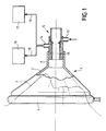
La figure 1 est une vue schématique, partiellement en coupe axiale, d'un masque d'assistance respiratoire comportant un dispositif tubulaire conforme à la présente invention.Figure 1 is a schematic view, partially in section axial, of a respiratory assistance mask comprising a device tubular according to the present invention.
La figure 2 montre, en coupe axiale, ledit dispositif tubulaire constituant l'embout du masque de la figure 1.Figure 2 shows, in axial section, said tubular device constituting the tip of the mask in Figure 1.
Les figures 3, 4 et 5 sont des coupes transversales du dispositif de la figure 2, respectivement selon les lignes III-III, IV-IV et V-V.Figures 3, 4 and 5 are cross sections of the device of Figure 2, respectively along lines III-III, IV-IV and V-V.
La figure 6 montre, en coupe axiale semblable à la figure 2, une variante de réalisation du dispositif tubulaire conforme à la présente invention.Figure 6 shows, in axial section similar to Figure 2, a alternative embodiment of the tubular device according to the present invention.
Les figures 7, 8 et 9 sont des coupes transversales du dispositif de la figure 6, respectivement selon les lignes VII-VII, VIII-VIII et IX-IX.Figures 7, 8 and 9 are cross sections of the device of Figure 6, respectively along lines VII-VII, VIII-VIII and IX-IX.
Le masque d'assistance respiratoire 1, conforme à la présente invention
et représenté sur la figure 1, comporte une coque rigide de forme
générale tronconique 2, pouvant être appliquée sur le visage 3 d'un patient
par l'intermédiaire d'un coussinet gonflable 4, bordant son ouverture
périphérique. Du côté opposé, ledit masque 1 comporte un dispositif tubulaire
5, fixé ou emboíté sur une saillie tubulaire 6 de ladite coque 2. Le
dispositif tubulaire 5 sert d'embout d'entrée et de sortie de gaz respiratoire
dans le masque 1. Eventuellement, il peut être relié à un appareil de
respiration artificielle par son extrémité proximale (opposée au patient 3). The respiratory assistance mask 1, in accordance with the present invention
and shown in Figure 1, has a rigid shell of shape
general frustoconical 2, can be applied to the
Comme le montrent plus en détail les figures 2 à 5, le dispositif
tubulaire 5 comporte un passage traversant interne 7 et, en partie médiane,
une paroi conique 8, saillant à l'intérieur dudit passage 7. La paroi
conique 8 a pour objet de défléchir, en direction de l'axe du passage 7,
des jets de gaz respiratoire injectés par des canaux périphériques 9, alimentés
à partir d'un embout d'amenée 10, par l'intermédiaire d'une
chambre annulaire périphérique 11.As shown in more detail in Figures 2 to 5, the device
tubular 5 has an internal through
Par ailleurs, du côté distal, le dispositif tubulaire 5 comporte une
chambre périphérique annulaire 12, coaxiale audit dispositif 5. La chambre
périphérique annulaire 12 communique avec l'intérieur du masque 1
par son orifice annulaire distal 13 et est pourvue, à son extrémité proximale,
d'un embout de sortie 14.Furthermore, on the distal side, the
Un filtre 15, fibreux ou poreux (coton, mousse synthétique,
etc...) est disposé dans la chambre périphérique annulaire 12, pour
amortir les turbulences gazeuses et, par suite, les trop fortes variations
de pression.A
Comme cela est représenté sur la figure 1, l'embout de sortie 14
peut être relié à un analyseur de gaz 16 et à un dispositif de mesure de
pression 17. Bien entendu, les liaisons 18 et 19 entre l'embout de sortie
14 et les dispositifs 16 et 17 sont prévues pour que le prélèvement de
gaz à analyser par la liaison 18 n'ait pas d'influence sur la mesure de
pression, via la liaison 19.As shown in Figure 1, the
Ainsi, grâce aux dispositifs 16 et 17, le praticien assistant le patient
3 connaít en permanence la composition du gaz dans le masque 1
(et notamment sa teneur en gaz carbonique) et la pression à l'intérieur
dudit masque. Il peut donc prendre les mesures d'intervention appropriées
en fonction desdites composition et pression du gaz.Thus, thanks to the
Dans la variante de réalisation du dispositif 5, montrée par les figures
6 à 9, on retrouve les éléments 7 à 15 précédemment décrits en
regard des figures 2 à 5. Cependant, on peut remarquer que cette variante
de réalisation comporte de plus, dans la paroi du passage 7 et dans
la paroi conique 8, des rainures 20, 21, 22 disposées radialement entre
les canaux périphériques 9, ainsi qu'au moins un orifice 23 traversant la
paroi de l'extrémité proximale du dispositif 5. Ainsi, si pour une raison
quelconque la partie proximale du dispositif 5 est bouchée, les rainures
20, 21, 22 et les orifices 23 constituent une mise à l'air libre évitant à la
pression du gaz respiratoire injecté d'atteindre des valeurs excessives,
susceptibles d'être préjudiciables au patient. On obtient ainsi une sécurité
de fonctionnement automatique, complétant l'éventuel dispositif de mesure
de pression 17.In the alternative embodiment of the
Bien que sur les figures, on ne les ait pas respectés, il va de soi
que le dispositif 5 peut comporter des canaux ou conduits d'injection de
médicaments et/ou d'eau.Although in the figures, we did not respect them, it goes without saying
that the
Par ailleurs, bien que ci-dessus on ait décrit, à l'aide desdites figures,
une application particulière du dispositif 5 à un masque respiratoire,
on comprendra aisément que ledit dispositif peut trouver de nombreuses
autres applications, par exemple comme sonde nasale, sonde buccale,
sonde trachéale, etc ... Bien entendu, les dimensions dudit dispositif sont
adaptées à chaque utilisation particulière.Furthermore, although above we have described, with the aid of said figures,
a particular application of the
Claims (10)
caractérisé en ce qu'il comporte, du côté distal, une chambre annulaire (12), disposée à la périphérie dudit dispositif tubulaire (5), coaxialement à celui-ci et communiquant avec le système respiratoire du patient par l'intermédiaire de l'orifice (13) formé par sa section annulaire distale, et en ce que ladite chambre annulaire (12) est pourvue de moyens (14) de liaison avec l'extérieur.Tubular respiratory assistance device (5), which forms a main channel (7) and which is intended to be connected by its distal end to a respiratory tract of a patient so that said main channel (7) connects to the outside the respiratory system of said patient, said device comprising at least one auxiliary channel (9) associated with deflection means (8) for injecting a jet of respiratory gas deflected towards the interior of said main channel (7) and intended for the ventilation of said patient,
characterized in that it comprises, on the distal side, an annular chamber (12), disposed at the periphery of said tubular device (5), coaxial therewith and communicating with the respiratory system of the patient via the orifice (13) formed by its distal annular section, and in that said annular chamber (12) is provided with means (14) for connection with the outside.
caractérisé en ce que lesdits moyens de liaison (14) sont disposés à l'extrémité proximale de ladite chambre (12).Respiratory assistance device according to claim 1,
characterized in that said connecting means (14) are arranged at the proximal end of said chamber (12).
caractérisé en ce que les gaz contenus dans ladite chambre font l'objet d'une analyse de composition et d'une mesure de pression, et en ce que des moyens (15) d'amortissement de turbulences gazeuses sont disposés dans ladite chambre (12).Respiratory assistance device according to one of claims 1 or 2,
characterized in that the gases contained in said chamber are subject to a composition analysis and a pressure measurement, and in that means (15) for damping gas turbulence are arranged in said chamber (12 ).
caractérisé en ce que lesdits moyens d'amortissement des turbulences gazeuses sont formés par un filtre d'une matière poreuse.Respiratory assistance device according to claim 3,
characterized in that said means for damping gas turbulence are formed by a filter of a porous material.
caractérisé en ce que lesdits moyens d'amortissement des turbulences gazeuses sont formés par un filtre annulaire d'une matière fibreuse. Respiratory assistance device according to claim 3,
characterized in that said means for damping gas turbulence are formed by an annular filter of a fibrous material.
caractérisé en ce qu'il comporte un réseau de rainures (20, 21, 22) pratiquées dans la paroi dudit canal principal (7) et au moins un orifice (23) traversant la partie proximale dudit dispositif (5), de façon à former une mise à l'air libre du système respiratoire dudit patient, en cas de bouchage accidentel de la partie proximale dudit dispositif (5).Respiratory assistance device according to any one of claims 1 to 5,
characterized in that it comprises a network of grooves (20, 21, 22) formed in the wall of said main channel (7) and at least one orifice (23) passing through the proximal part of said device (5), so as to form venting the respiratory system of said patient in the event of accidental blockage of the proximal part of said device (5).
caractérisé en ce qu'il comporte, comme embout d'entrée et de sortie de gaz respiratoire, le dispositif spécifié sous l'une quelconque des revendications 1 à 6.Breathing assistance mask intended to be applied to the face of a patient,
characterized in that it comprises, as an inlet and outlet nozzle for respiratory gas, the device specified under any one of claims 1 to 6.
caractérisé en ce que ledit dispositif (5) est solidaire dudit masque.Respiratory assistance mask according to claim 7,
characterized in that said device (5) is integral with said mask.
caractérisé en ce que ledit dispositif (5) est monté de façon amovible sur ledit masque.Respiratory assistance mask according to claim 7,
characterized in that said device (5) is removably mounted on said mask.
caractérisé en ce que ledit dispositif (5) est emboítable sur ledit masque.Respiratory assistance mask according to claim 9,
characterized in that said device (5) is nestable on said mask.
Applications Claiming Priority (2)
| Application Number | Priority Date | Filing Date | Title |
|---|---|---|---|
| FR9713430 | 1997-10-27 | ||
| FR9713430A FR2770137B1 (en) | 1997-10-27 | 1997-10-27 | RESPIRATORY ASSISTANCE DEVICE |
Publications (2)
| Publication Number | Publication Date |
|---|---|
| EP0911051A1 true EP0911051A1 (en) | 1999-04-28 |
| EP0911051B1 EP0911051B1 (en) | 2003-06-11 |
Family
ID=9512676
Family Applications (1)
| Application Number | Title | Priority Date | Filing Date |
|---|---|---|---|
| EP98402655A Expired - Lifetime EP0911051B1 (en) | 1997-10-27 | 1998-10-26 | Respiratory assistance device |
Country Status (12)
| Country | Link |
|---|---|
| US (1) | US6273087B1 (en) |
| EP (1) | EP0911051B1 (en) |
| JP (1) | JP4055959B2 (en) |
| CN (1) | CN1182888C (en) |
| AT (1) | ATE242652T1 (en) |
| CA (1) | CA2274021C (en) |
| DE (1) | DE69815464T2 (en) |
| DK (1) | DK0911051T3 (en) |
| ES (1) | ES2201424T3 (en) |
| FR (1) | FR2770137B1 (en) |
| PT (1) | PT911051E (en) |
| WO (1) | WO1999021603A1 (en) |
Cited By (12)
| Publication number | Priority date | Publication date | Assignee | Title |
|---|---|---|---|---|
| WO2005007056A2 (en) | 2003-07-22 | 2005-01-27 | Zinder, Oren | A respiratory aid system and method |
| FR2899483A1 (en) * | 2006-04-06 | 2007-10-12 | Georges Boussignac | ARTIFICIAL BREATHING DEVICE FOR PATIENTS WITH HYPOXEMIA OR ANOXEMIA |
| FR2911073A1 (en) * | 2007-01-08 | 2008-07-11 | Georges Boussignac | Artificial respiration device for patient suffering from e.g. cardiac arrest, has pressure drop element assuring that utilization pressure of gas is equal to higher value of utilization value range when supply pressure has maximum value |
| FR2912660A1 (en) * | 2007-02-15 | 2008-08-22 | Georges Boussignac | Artificial respiration device for intensive care of patient, has controlling unit controlling entry of exterior air in tubular element at beginning of each decompression imposed to thoracic cage of person |
| FR2920001A1 (en) * | 2007-08-17 | 2009-02-20 | Jacek Wasylkiewicz | High concentration oxygen mask's nozzle for respiratory monitoring assembly, has sampling unit for sampling exhaust gas released by patient, and connected to determination device for determining respiratory frequency of patient |
| WO2010022363A1 (en) | 2008-08-22 | 2010-02-25 | Breathe Technologies, Inc. | Methods and devices for providing mechanical ventilation with an open airway interface |
| EP2186539A1 (en) | 2008-11-17 | 2010-05-19 | Jacek Wasylkiewicz | Specific nozzle for a High-Concentration Oxygen mask. |
| WO2011131974A1 (en) * | 2010-04-19 | 2011-10-27 | Intersurgical Ag | Improvements relating to respiratory apparatus |
| WO2012104517A1 (en) | 2011-02-03 | 2012-08-09 | Georges Boussignac | Artificial respiration device for resuscitating a person in a state of cardiac arrest |
| WO2014033401A1 (en) * | 2012-08-28 | 2014-03-06 | Georges Boussignac | Respiratory assistance device, nasal appliance and respiratory assistance mask |
| WO2019173894A1 (en) | 2018-03-15 | 2019-09-19 | Vo2 Master Health Sensors Inc. | Device for measuring a person's ventilation including oxygen-consumption |
| US11284814B2 (en) | 2016-04-14 | 2022-03-29 | Vo2 Master Health Sensors Inc. | Device for measuring a user's oxygen-consumption |
Families Citing this family (40)
| Publication number | Priority date | Publication date | Assignee | Title |
|---|---|---|---|---|
| FR2782925B1 (en) * | 1998-09-03 | 2000-12-29 | Georges Boussignac | DEVICE FOR BREATHING ASSISTANCE |
| DE29909671U1 (en) * | 1999-06-02 | 1999-09-02 | Draeger Medizintech Gmbh | Coupling for a breathing hose system |
| CA2314692C (en) * | 2000-07-28 | 2009-05-19 | Ian Alexander Sloan | Universal respiratory device coupler |
| FR2831824B1 (en) * | 2001-11-06 | 2004-01-23 | Georges Boussignac | DEVICE FOR RESPIRATORY ASSISTANCE |
| FR2836384B1 (en) * | 2002-02-27 | 2004-12-10 | Georges Boussignac | RESPIRATORY ASSISTANCE DEVICE |
| AU2003245018A1 (en) * | 2002-07-22 | 2004-02-09 | Hasdi Matarasso | A respiratory aid apparatus and method |
| US20040089305A1 (en) * | 2002-11-13 | 2004-05-13 | Vallarta John-Eric S. | Endotracheal tube safety device connector |
| US7749169B2 (en) * | 2003-04-10 | 2010-07-06 | Intoximeters, Inc. | Handheld breath tester housing and mouthpiece |
| US8336549B2 (en) * | 2003-12-29 | 2012-12-25 | Ramses Nashed | Disposable anesthesia face mask |
| DE102004030070B3 (en) * | 2004-06-23 | 2005-12-08 | Drägerwerk AG | Respiratory mask with individual adaptation to the face shape |
| FR2873042B1 (en) * | 2004-07-19 | 2007-12-14 | Fabrice Ghiron | OXYGEN MASK TOOL, OXYGEN MASK AND CORRESPONDING RESPIRATORY MONITORING ASSEMBLY |
| US8042539B2 (en) * | 2004-12-10 | 2011-10-25 | Respcare, Inc. | Hybrid ventilation mask with nasal interface and method for configuring such a mask |
| US20060217625A1 (en) * | 2005-03-25 | 2006-09-28 | Forrester Macquorn R Jr | Mouthpiece for breath tester |
| US20070113852A1 (en) * | 2005-11-18 | 2007-05-24 | Christopher Martin | Snap-in deflector for respiratory mask |
| US7578294B2 (en) | 2005-12-02 | 2009-08-25 | Allegiance Corporation | Nasal continuous positive airway pressure device and system |
| JP4998878B2 (en) * | 2007-02-16 | 2012-08-15 | 日本光電工業株式会社 | Carbon dioxide gas measurement nose mask |
| US8851072B2 (en) * | 2007-02-16 | 2014-10-07 | Wasatch Manufacturing, Llc | Supplemental air diffusion devices, kits and methods |
| US8826905B2 (en) * | 2007-06-01 | 2014-09-09 | Ramses Nashed | Respiratory face mask and breathing circuit assembly |
| US8251876B2 (en) | 2008-04-22 | 2012-08-28 | Hill-Rom Services, Inc. | Breathing exercise apparatus |
| US8893716B2 (en) * | 2009-10-20 | 2014-11-25 | Mercury Enterprises, Inc. | Disposable breathing assistance device with manometer |
| US8726900B1 (en) * | 2010-02-01 | 2014-05-20 | Ramses Nashed | Demand anesthetic gas delivery system with disposable breathing and scavenging circuit |
| US10086166B1 (en) | 2010-02-01 | 2018-10-02 | Sedation Systems, Llc | Demand gas flow valve apparatus |
| US10265492B2 (en) * | 2010-04-30 | 2019-04-23 | Resmed Limited | Respiratory mask |
| US9180271B2 (en) | 2012-03-05 | 2015-11-10 | Hill-Rom Services Pte. Ltd. | Respiratory therapy device having standard and oscillatory PEP with nebulizer |
| US9713687B2 (en) * | 2012-08-21 | 2017-07-25 | Philip Morris Usa Inc. | Ventilator aerosol delivery system with transition adapter for introducing carrier gas |
| US9370635B2 (en) | 2012-08-23 | 2016-06-21 | Mercury Enterprises, Inc. | Optimized breathing assistance device |
| EP2895225B1 (en) | 2012-09-14 | 2017-11-08 | Fisher & Paykel Healthcare Limited | External sensor arrangement for patient interface |
| GB2506621B (en) * | 2012-10-03 | 2018-08-08 | Intersurgical Ag | Respiratory mask |
| WO2014109749A1 (en) * | 2013-01-10 | 2014-07-17 | Rollins Offord L | Multi-function oxygen mask |
| WO2014129912A1 (en) | 2013-02-20 | 2014-08-28 | Fisher & Paykel Healthcare Limited | Connector for multiple sized connections |
| CN104415441A (en) * | 2013-09-07 | 2015-03-18 | 王家松 | Simple multi-functional cannula guiding and protecting machine |
| FR3022146A1 (en) * | 2014-06-13 | 2015-12-18 | Vygon | RESPIRATORY ASSISTANCE DEVICE, NASAL APPARATUS AND RESPIRATORY ASSISTANCE MASK |
| US11602607B2 (en) | 2014-09-24 | 2023-03-14 | Fisher & Paykel Healthcare Limited | Swivel connector |
| FR3028766A1 (en) * | 2014-11-24 | 2016-05-27 | Georges Boussignac | DEVICE FOR VISUALIZING THE OPERATION OF A RESPIRATORY ASSISTANCE DEVICE, AN ASSEMBLY WITH A BONDING SYSTEM AND A METHOD OF USE |
| JP6480598B2 (en) | 2015-04-02 | 2019-03-13 | ヒル−ロム サービシーズ プライヴェート リミテッド | Respirator manifold |
| FR3050381B1 (en) * | 2016-04-22 | 2018-04-20 | Georges Boussignac | CATHETER OF MIXED MEASUREMENTS FOR RESPIRATORY INTUBATION PROBE |
| CN105963838B (en) * | 2016-06-08 | 2018-12-14 | 湖南明康中锦医疗科技发展有限公司 | A kind of empty oxygen mixed structure and ventilator for ventilator |
| TWI678198B (en) | 2017-11-28 | 2019-12-01 | 財團法人工業技術研究院 | Adjustable respirator shell |
| US11696996B2 (en) * | 2018-06-27 | 2023-07-11 | Hu-Friedy Mfg. Co., Llc | Capnography tube fitting |
| DE102019003395A1 (en) | 2019-05-14 | 2020-11-19 | Drägerwerk AG & Co. KGaA | Connection arrangement for establishing a fluid connection between a medical device and a patient-side coupling unit |
Citations (8)
| Publication number | Priority date | Publication date | Assignee | Title |
|---|---|---|---|---|
| US4558708A (en) * | 1984-10-24 | 1985-12-17 | Tri-Med, Inc. | Patient's airway adapter to withdraw a patient's gas samples for testing free of sputum mucus and/or condensed water, by utilizing a hollow cylindrical hydrophobic liquid baffle |
| EP0390684A1 (en) * | 1989-03-31 | 1990-10-03 | Georges Boussignac | Respiratory assistance device |
| DE9202198U1 (en) * | 1992-02-20 | 1992-06-11 | Klein, Christoph, 5205 St Augustin, De | |
| GB2267661A (en) * | 1992-06-11 | 1993-12-15 | Pall Corp | Heat and moisture exchanging filters |
| EP0640355A1 (en) * | 1993-08-26 | 1995-03-01 | Georges Boussignac | Tube for respiratory assistance |
| US5474060A (en) * | 1993-08-23 | 1995-12-12 | Evans; David | Face mask with gas sampling port |
| EP0701834A1 (en) * | 1994-09-16 | 1996-03-20 | Georges Boussignac | Respiratory assistance device |
| WO1997006843A1 (en) * | 1995-08-16 | 1997-02-27 | David Weintraub | A computer controlled portable ventilator |
Family Cites Families (14)
| Publication number | Priority date | Publication date | Assignee | Title |
|---|---|---|---|---|
| US3661528A (en) | 1970-04-02 | 1972-05-09 | Instrumentation Associates Inc | Breath sampler |
| FR2174782B1 (en) * | 1972-03-10 | 1975-03-21 | Lafourcade Jean Michel | |
| US4207884A (en) * | 1976-12-20 | 1980-06-17 | Max Isaacson | Pressure controlled breathing apparatus |
| US4592349A (en) * | 1981-08-10 | 1986-06-03 | Bird F M | Ventilator having an oscillatory inspiratory phase and method |
| IL76939A (en) * | 1984-11-13 | 1990-01-18 | Andros Analyzers Inc | Adaptor assembly for airway tube |
| US5166075A (en) * | 1986-08-13 | 1992-11-24 | Nellcor Incorporated | Method for determining whether respiratory gas is present in a gaseous sample |
| US4852583A (en) * | 1987-01-16 | 1989-08-01 | Spacelabs, Inc. | Airway adapter |
| US5335656A (en) * | 1988-04-15 | 1994-08-09 | Salter Laboratories | Method and apparatus for inhalation of treating gas and sampling of exhaled gas for quantitative analysis |
| US5465728A (en) * | 1994-01-11 | 1995-11-14 | Phillips; Michael | Breath collection |
| US5642726A (en) * | 1994-10-18 | 1997-07-01 | Alcove Medical, Inc. | Reduced internal volume neonatal suction adaptor |
| US6129680A (en) * | 1995-06-19 | 2000-10-10 | Btg International Limited | Animal exhalation monitoring |
| US5789660A (en) * | 1996-07-15 | 1998-08-04 | Novametrix Medical Systems, Inc. | Multiple function airway adapter |
| US5829429A (en) * | 1997-04-21 | 1998-11-03 | Hughes; Arthur R. | Acoustic respiratory therapy apparatus |
| US5979444A (en) * | 1997-06-17 | 1999-11-09 | Sherrod; James B. | Portable CPR breathing apparatus |
-
1997
- 1997-10-27 FR FR9713430A patent/FR2770137B1/en not_active Expired - Lifetime
-
1998
- 1998-10-26 CA CA002274021A patent/CA2274021C/en not_active Expired - Lifetime
- 1998-10-26 CN CNB988016044A patent/CN1182888C/en not_active Expired - Fee Related
- 1998-10-26 PT PT98402655T patent/PT911051E/en unknown
- 1998-10-26 DK DK98402655T patent/DK0911051T3/en active
- 1998-10-26 EP EP98402655A patent/EP0911051B1/en not_active Expired - Lifetime
- 1998-10-26 WO PCT/FR1998/002280 patent/WO1999021603A1/en active Application Filing
- 1998-10-26 AT AT98402655T patent/ATE242652T1/en active
- 1998-10-26 US US09/319,307 patent/US6273087B1/en not_active Expired - Lifetime
- 1998-10-26 DE DE69815464T patent/DE69815464T2/en not_active Expired - Lifetime
- 1998-10-26 ES ES98402655T patent/ES2201424T3/en not_active Expired - Lifetime
- 1998-10-26 JP JP52339999A patent/JP4055959B2/en not_active Expired - Lifetime
Patent Citations (8)
| Publication number | Priority date | Publication date | Assignee | Title |
|---|---|---|---|---|
| US4558708A (en) * | 1984-10-24 | 1985-12-17 | Tri-Med, Inc. | Patient's airway adapter to withdraw a patient's gas samples for testing free of sputum mucus and/or condensed water, by utilizing a hollow cylindrical hydrophobic liquid baffle |
| EP0390684A1 (en) * | 1989-03-31 | 1990-10-03 | Georges Boussignac | Respiratory assistance device |
| DE9202198U1 (en) * | 1992-02-20 | 1992-06-11 | Klein, Christoph, 5205 St Augustin, De | |
| GB2267661A (en) * | 1992-06-11 | 1993-12-15 | Pall Corp | Heat and moisture exchanging filters |
| US5474060A (en) * | 1993-08-23 | 1995-12-12 | Evans; David | Face mask with gas sampling port |
| EP0640355A1 (en) * | 1993-08-26 | 1995-03-01 | Georges Boussignac | Tube for respiratory assistance |
| EP0701834A1 (en) * | 1994-09-16 | 1996-03-20 | Georges Boussignac | Respiratory assistance device |
| WO1997006843A1 (en) * | 1995-08-16 | 1997-02-27 | David Weintraub | A computer controlled portable ventilator |
Cited By (24)
| Publication number | Priority date | Publication date | Assignee | Title |
|---|---|---|---|---|
| EP1656172A4 (en) * | 2003-07-22 | 2010-07-28 | Hasdi Matarasso | A respiratory aid system and method |
| EP1656172A2 (en) * | 2003-07-22 | 2006-05-17 | Hasdi Matarasso | A respiratory aid system and method |
| WO2005007056A2 (en) | 2003-07-22 | 2005-01-27 | Zinder, Oren | A respiratory aid system and method |
| FR2899483A1 (en) * | 2006-04-06 | 2007-10-12 | Georges Boussignac | ARTIFICIAL BREATHING DEVICE FOR PATIENTS WITH HYPOXEMIA OR ANOXEMIA |
| WO2007118973A1 (en) * | 2006-04-06 | 2007-10-25 | Georges Boussignac | Artificial respiration device for patients suffering from hypoxemia or anoxemia |
| US8312882B2 (en) | 2006-04-06 | 2012-11-20 | Georges Boussignac | Artificial respiration device for patients suffering from hypoxemia or anoxemia |
| FR2911073A1 (en) * | 2007-01-08 | 2008-07-11 | Georges Boussignac | Artificial respiration device for patient suffering from e.g. cardiac arrest, has pressure drop element assuring that utilization pressure of gas is equal to higher value of utilization value range when supply pressure has maximum value |
| FR2912660A1 (en) * | 2007-02-15 | 2008-08-22 | Georges Boussignac | Artificial respiration device for intensive care of patient, has controlling unit controlling entry of exterior air in tubular element at beginning of each decompression imposed to thoracic cage of person |
| WO2008113913A2 (en) * | 2007-02-15 | 2008-09-25 | Georges Boussignac | Method and device for resuscitating a person in cardiac arrest condition |
| WO2008113913A3 (en) * | 2007-02-15 | 2008-11-13 | Georges Boussignac | Method and device for resuscitating a person in cardiac arrest condition |
| FR2920001A1 (en) * | 2007-08-17 | 2009-02-20 | Jacek Wasylkiewicz | High concentration oxygen mask's nozzle for respiratory monitoring assembly, has sampling unit for sampling exhaust gas released by patient, and connected to determination device for determining respiratory frequency of patient |
| EP2326376A1 (en) * | 2008-08-22 | 2011-06-01 | Breathe Technologies, Inc. | Methods and devices for providing mechanical ventilation with an open airway interface |
| WO2010022363A1 (en) | 2008-08-22 | 2010-02-25 | Breathe Technologies, Inc. | Methods and devices for providing mechanical ventilation with an open airway interface |
| EP2326376A4 (en) * | 2008-08-22 | 2014-10-01 | Breathe Technologies Inc | Methods and devices for providing mechanical ventilation with an open airway interface |
| EP2186539A1 (en) | 2008-11-17 | 2010-05-19 | Jacek Wasylkiewicz | Specific nozzle for a High-Concentration Oxygen mask. |
| WO2011131974A1 (en) * | 2010-04-19 | 2011-10-27 | Intersurgical Ag | Improvements relating to respiratory apparatus |
| RU2556520C2 (en) * | 2010-04-19 | 2015-07-10 | Интерсерджикал Аг | Development of breathing appliance |
| US10806880B2 (en) | 2010-04-19 | 2020-10-20 | Intersurgical Ag | Respiratory apparatus |
| WO2012104517A1 (en) | 2011-02-03 | 2012-08-09 | Georges Boussignac | Artificial respiration device for resuscitating a person in a state of cardiac arrest |
| US10195382B2 (en) | 2011-02-03 | 2019-02-05 | Georges Boussignac | Artificial respiration device for resuscitating a person in a state of cardiac arrest |
| WO2014033401A1 (en) * | 2012-08-28 | 2014-03-06 | Georges Boussignac | Respiratory assistance device, nasal appliance and respiratory assistance mask |
| FR2994852A1 (en) * | 2012-08-28 | 2014-03-07 | Georges Boussignac | RESPIRATORY ASSISTANCE DEVICE, NASAL APPARATUS AND RESPIRATORY ASSISTANCE MASK |
| US11284814B2 (en) | 2016-04-14 | 2022-03-29 | Vo2 Master Health Sensors Inc. | Device for measuring a user's oxygen-consumption |
| WO2019173894A1 (en) | 2018-03-15 | 2019-09-19 | Vo2 Master Health Sensors Inc. | Device for measuring a person's ventilation including oxygen-consumption |
Also Published As
| Publication number | Publication date |
|---|---|
| ATE242652T1 (en) | 2003-06-15 |
| FR2770137B1 (en) | 2000-01-28 |
| FR2770137A1 (en) | 1999-04-30 |
| CN1182888C (en) | 2005-01-05 |
| JP4055959B2 (en) | 2008-03-05 |
| WO1999021603A1 (en) | 1999-05-06 |
| DE69815464T2 (en) | 2004-05-13 |
| ES2201424T3 (en) | 2004-03-16 |
| PT911051E (en) | 2003-09-30 |
| JP2001507270A (en) | 2001-06-05 |
| DE69815464D1 (en) | 2003-07-17 |
| US6273087B1 (en) | 2001-08-14 |
| CA2274021A1 (en) | 1999-05-06 |
| CA2274021C (en) | 2008-01-08 |
| EP0911051B1 (en) | 2003-06-11 |
| CN1242711A (en) | 2000-01-26 |
| DK0911051T3 (en) | 2003-07-21 |
Similar Documents
| Publication | Publication Date | Title |
|---|---|---|
| EP0911051B1 (en) | Respiratory assistance device | |
| CA2030546C (en) | Apparatus for assisted ventilation | |
| EP2001540B1 (en) | Artificial respiration device for patients suffering from hypoxemia or anoxemia | |
| CA2695570C (en) | Breathing assistance device | |
| EP0978291B1 (en) | Respiratory assistance device | |
| EP1340515B1 (en) | Device for breathing assistance | |
| EP0701834B1 (en) | Respiratory assistance device | |
| EP0245142B1 (en) | Tube for respiratory assistance | |
| EP0888792B1 (en) | Suction endotracheal tube for use in a patient under artificial ventilation | |
| EP0983772B1 (en) | Respiratory assistance device | |
| FR2479003A1 (en) | DEVICE FOR ADMINISTERING ANESTHETIC GAS TO A PATIENT | |
| EP2239004B1 (en) | Respiratory aid device and measurement system comprising such a device | |
| FR2921840A1 (en) | Tubular respiratory assistance device for e.g. child in hospital, has sealing unit surrounding distal end of device and assuring sealed gaseous communication, at throat of patient, between trachea of patient and main channel | |
| FR2942967A1 (en) | RESPIRATORY ASSISTANCE DEVICE | |
| FR2994852A1 (en) | RESPIRATORY ASSISTANCE DEVICE, NASAL APPARATUS AND RESPIRATORY ASSISTANCE MASK | |
| FR2597754A1 (en) | Tube for respiratory assistance | |
| CA2130880C (en) | Assisted ventilation tube | |
| WO1994000175A1 (en) | Endotracheal tube |
Legal Events
| Date | Code | Title | Description |
|---|---|---|---|
| PUAI | Public reference made under article 153(3) epc to a published international application that has entered the european phase |
Free format text: ORIGINAL CODE: 0009012 |
|
| AK | Designated contracting states |
Kind code of ref document: A1 Designated state(s): AT BE CH DE DK ES FI GB GR IE IT LI LU MC NL PT SE |
|
| AX | Request for extension of the european patent |
Free format text: AL;LT;LV;MK;RO;SI |
|
| 17P | Request for examination filed |
Effective date: 19990602 |
|
| RAP1 | Party data changed (applicant data changed or rights of an application transferred) |
Owner name: LABRUNE, JEAN-CLAUDE Owner name: BOUSSIGNAC, GEORGES |
|
| RIN1 | Information on inventor provided before grant (corrected) |
Inventor name: LABRUNE, JEAN-CLAUDE Inventor name: BOUSSIGNAC, GEORGES |
|
| K1C1 | Correction of patent application (title page) published |
Effective date: 19990428 |
|
| AKX | Designation fees paid |
Free format text: AT BE CH DE DK ES FI GB GR IE IT LI LU MC NL PT SE |
|
| 17Q | First examination report despatched |
Effective date: 20020628 |
|
| GRAH | Despatch of communication of intention to grant a patent |
Free format text: ORIGINAL CODE: EPIDOS IGRA |
|
| GRAH | Despatch of communication of intention to grant a patent |
Free format text: ORIGINAL CODE: EPIDOS IGRA |
|
| GRAA | (expected) grant |
Free format text: ORIGINAL CODE: 0009210 |
|
| AK | Designated contracting states |
Designated state(s): AT BE CH DE DK ES FI GB GR IE IT LI LU MC NL PT SE |
|
| PG25 | Lapsed in a contracting state [announced via postgrant information from national office to epo] |
Ref country code: FI Free format text: LAPSE BECAUSE OF FAILURE TO SUBMIT A TRANSLATION OF THE DESCRIPTION OR TO PAY THE FEE WITHIN THE PRESCRIBED TIME-LIMIT Effective date: 20030611 |
|
| REG | Reference to a national code |
Ref country code: GB Ref legal event code: FG4D Free format text: NOT ENGLISH |
|
| REG | Reference to a national code |
Ref country code: CH Ref legal event code: NV Representative=s name: CRONIN INTELLECTUAL PROPERTY Ref country code: CH Ref legal event code: EP |
|
| GBT | Gb: translation of ep patent filed (gb section 77(6)(a)/1977) | ||
| REG | Reference to a national code |
Ref country code: IE Ref legal event code: FG4D Free format text: FRENCH |
|
| REF | Corresponds to: |
Ref document number: 69815464 Country of ref document: DE Date of ref document: 20030717 Kind code of ref document: P |
|
| REG | Reference to a national code |
Ref country code: DK Ref legal event code: T3 |
|
| PG25 | Lapsed in a contracting state [announced via postgrant information from national office to epo] |
Ref country code: GR Free format text: LAPSE BECAUSE OF FAILURE TO SUBMIT A TRANSLATION OF THE DESCRIPTION OR TO PAY THE FEE WITHIN THE PRESCRIBED TIME-LIMIT Effective date: 20030911 |
|
| REG | Reference to a national code |
Ref country code: SE Ref legal event code: TRGR |
|
| REG | Reference to a national code |
Ref country code: PT Ref legal event code: SC4A Free format text: AVAILABILITY OF NATIONAL TRANSLATION Effective date: 20030812 |
|
| PG25 | Lapsed in a contracting state [announced via postgrant information from national office to epo] |
Ref country code: MC Free format text: LAPSE BECAUSE OF NON-PAYMENT OF DUE FEES Effective date: 20031031 |
|
| REG | Reference to a national code |
Ref country code: ES Ref legal event code: FG2A Ref document number: 2201424 Country of ref document: ES Kind code of ref document: T3 |
|
| PLBE | No opposition filed within time limit |
Free format text: ORIGINAL CODE: 0009261 |
|
| STAA | Information on the status of an ep patent application or granted ep patent |
Free format text: STATUS: NO OPPOSITION FILED WITHIN TIME LIMIT |
|
| 26N | No opposition filed |
Effective date: 20040312 |
|
| REG | Reference to a national code |
Ref country code: CH Ref legal event code: PCAR Free format text: CRONIN INTELLECTUAL PROPERTY;CHEMIN DE PRECOSSY 31;1260 NYON (CH) |
|
| PGFP | Annual fee paid to national office [announced via postgrant information from national office to epo] |
Ref country code: AT Payment date: 20100917 Year of fee payment: 13 |
|
| PGFP | Annual fee paid to national office [announced via postgrant information from national office to epo] |
Ref country code: LU Payment date: 20110926 Year of fee payment: 14 |
|
| REG | Reference to a national code |
Ref country code: AT Ref legal event code: MM01 Ref document number: 242652 Country of ref document: AT Kind code of ref document: T Effective date: 20121026 |
|
| PG25 | Lapsed in a contracting state [announced via postgrant information from national office to epo] |
Ref country code: AT Free format text: LAPSE BECAUSE OF NON-PAYMENT OF DUE FEES Effective date: 20121026 |
|
| PG25 | Lapsed in a contracting state [announced via postgrant information from national office to epo] |
Ref country code: LU Free format text: LAPSE BECAUSE OF NON-PAYMENT OF DUE FEES Effective date: 20121026 |
|
| PGFP | Annual fee paid to national office [announced via postgrant information from national office to epo] |
Ref country code: CH Payment date: 20170908 Year of fee payment: 20 Ref country code: GB Payment date: 20170801 Year of fee payment: 20 |
|
| PGFP | Annual fee paid to national office [announced via postgrant information from national office to epo] |
Ref country code: IE Payment date: 20170721 Year of fee payment: 20 Ref country code: BE Payment date: 20170721 Year of fee payment: 20 Ref country code: DK Payment date: 20170727 Year of fee payment: 20 Ref country code: SE Payment date: 20170727 Year of fee payment: 20 |
|
| PGFP | Annual fee paid to national office [announced via postgrant information from national office to epo] |
Ref country code: DE Payment date: 20170725 Year of fee payment: 20 |
|
| PGFP | Annual fee paid to national office [announced via postgrant information from national office to epo] |
Ref country code: PT Payment date: 20171023 Year of fee payment: 20 Ref country code: ES Payment date: 20171107 Year of fee payment: 20 Ref country code: IT Payment date: 20171005 Year of fee payment: 20 Ref country code: NL Payment date: 20171019 Year of fee payment: 20 |
|
| REG | Reference to a national code |
Ref country code: CH Ref legal event code: PCAR Free format text: NEW ADDRESS: CHEMIN DE LA VUARPILLIERE 29, 1260 NYON (CH) |
|
| REG | Reference to a national code |
Ref country code: DE Ref legal event code: R071 Ref document number: 69815464 Country of ref document: DE |
|
| REG | Reference to a national code |
Ref country code: CH Ref legal event code: PL Ref country code: NL Ref legal event code: MK Effective date: 20181025 |
|
| REG | Reference to a national code |
Ref country code: DK Ref legal event code: EUP Effective date: 20181026 |
|
| REG | Reference to a national code |
Ref country code: GB Ref legal event code: PE20 Expiry date: 20181025 |
|
| REG | Reference to a national code |
Ref country code: IE Ref legal event code: MK9A |
|
| REG | Reference to a national code |
Ref country code: SE Ref legal event code: EUG |
|
| REG | Reference to a national code |
Ref country code: BE Ref legal event code: MK Effective date: 20181026 |
|
| PG25 | Lapsed in a contracting state [announced via postgrant information from national office to epo] |
Ref country code: PT Free format text: LAPSE BECAUSE OF EXPIRATION OF PROTECTION Effective date: 20181106 Ref country code: IE Free format text: LAPSE BECAUSE OF EXPIRATION OF PROTECTION Effective date: 20181026 |
|
| PG25 | Lapsed in a contracting state [announced via postgrant information from national office to epo] |
Ref country code: GB Free format text: LAPSE BECAUSE OF EXPIRATION OF PROTECTION Effective date: 20181025 |
|
| REG | Reference to a national code |
Ref country code: ES Ref legal event code: FD2A Effective date: 20200721 |
|
| PG25 | Lapsed in a contracting state [announced via postgrant information from national office to epo] |
Ref country code: ES Free format text: LAPSE BECAUSE OF EXPIRATION OF PROTECTION Effective date: 20181027 |