EP0911894A1 - Polymer secondary batteries - Google Patents
Polymer secondary batteries Download PDFInfo
- Publication number
- EP0911894A1 EP0911894A1 EP98119870A EP98119870A EP0911894A1 EP 0911894 A1 EP0911894 A1 EP 0911894A1 EP 98119870 A EP98119870 A EP 98119870A EP 98119870 A EP98119870 A EP 98119870A EP 0911894 A1 EP0911894 A1 EP 0911894A1
- Authority
- EP
- European Patent Office
- Prior art keywords
- active material
- material layer
- negative electrode
- secondary battery
- electrode active
- Prior art date
- Legal status (The legal status is an assumption and is not a legal conclusion. Google has not performed a legal analysis and makes no representation as to the accuracy of the status listed.)
- Granted
Links
Images


Classifications
-
- H—ELECTRICITY
- H01—ELECTRIC ELEMENTS
- H01M—PROCESSES OR MEANS, e.g. BATTERIES, FOR THE DIRECT CONVERSION OF CHEMICAL ENERGY INTO ELECTRICAL ENERGY
- H01M4/00—Electrodes
- H01M4/02—Electrodes composed of, or comprising, active material
- H01M4/36—Selection of substances as active materials, active masses, active liquids
- H01M4/60—Selection of substances as active materials, active masses, active liquids of organic compounds
- H01M4/602—Polymers
- H01M4/606—Polymers containing aromatic main chain polymers
-
- H—ELECTRICITY
- H01—ELECTRIC ELEMENTS
- H01M—PROCESSES OR MEANS, e.g. BATTERIES, FOR THE DIRECT CONVERSION OF CHEMICAL ENERGY INTO ELECTRICAL ENERGY
- H01M4/00—Electrodes
- H01M4/02—Electrodes composed of, or comprising, active material
- H01M4/36—Selection of substances as active materials, active masses, active liquids
- H01M4/60—Selection of substances as active materials, active masses, active liquids of organic compounds
- H01M4/602—Polymers
- H01M4/606—Polymers containing aromatic main chain polymers
- H01M4/608—Polymers containing aromatic main chain polymers containing heterocyclic rings
-
- Y—GENERAL TAGGING OF NEW TECHNOLOGICAL DEVELOPMENTS; GENERAL TAGGING OF CROSS-SECTIONAL TECHNOLOGIES SPANNING OVER SEVERAL SECTIONS OF THE IPC; TECHNICAL SUBJECTS COVERED BY FORMER USPC CROSS-REFERENCE ART COLLECTIONS [XRACs] AND DIGESTS
- Y02—TECHNOLOGIES OR APPLICATIONS FOR MITIGATION OR ADAPTATION AGAINST CLIMATE CHANGE
- Y02E—REDUCTION OF GREENHOUSE GAS [GHG] EMISSIONS, RELATED TO ENERGY GENERATION, TRANSMISSION OR DISTRIBUTION
- Y02E60/00—Enabling technologies; Technologies with a potential or indirect contribution to GHG emissions mitigation
- Y02E60/10—Energy storage using batteries
Definitions
- This invention relates to polymer secondary batteries.
- a polymer secondary battery in which the electrode active material constituting at least one of the negative and positive electrodes comprises an electrically conductive polymeric material may be utilized as a battery power supply for IC memory backup (Japanese Patent Laid-Open No. 36319/'88).
- a secondary battery having a high capacity per unit weight of the electrode active material and excellent charge-discharge cycle characteristics can be obtained by using polyaniline as the electrically conductive polymeric material, and this makes it possible to construct an IC memory backup equipped with a battery power supply having higher performance.
- Japanese Patent Laid-Open No. 62451/'91 discloses an electrode for aqueous solution type batteries which comprises an electrochemically polymerized polyaniline matrix and a polymer chemically bonded to the polyaniline and containing an organic dopant having a sulfonic group.
- an object of the present invention is to provide a polymer secondary battery which has a high rate of appearance of capacity, is capable of quick charging and discharging, and exhibits excellent cycle characteristics.
- the present invention relates to a polymer secondary battery comprising a pair of current collectors and electrodes arranged in opposed relationship with an electrolytic solution-containing separator or a solid electrolyte interposed therebetween, the polymer secondary battery having a structure in which, with respect to one or both of the positive and negative electrodes, at least one layer of a material capable of causing an oxidation-reduction reaction based on the same chemical species is laminated to an active material layer constituting the electrode, the material used for the negative electrode having a formal oxidation-reduction potential higher than that of the active material layer adjacent to the current collector and the material used for the positive electrode having a formal oxidation-reduction potential lower than that of the active material layer adjacent to the current collector.
- the negative electrode comprises two or more active material layers each consisting of a polymer selected from among quinone polymers, nitrogen-containing heterocyclic compound polymers, nitrogen-containing condensed heterocyclic compound polymers and polyaniline type polymers.
- a first negative electrode active material layer adjacent to the current collector consists of a polymer selected from among nitrogen-containing heterocyclic compound polymers and nitrogen-containing condensed heterocyclic compound polymers
- a second negative electrode active material layer formed on the first negative electrode active material layer consists of a polymer selected from among quinone polymers, nitrogen-containing heterocyclic compound polymers, nitrogen-containing condensed heterocyclic compound polymers and polyaniline type polymer.
- the polymer secondary battery of the present invention generally has a structure in which, with respect to one or both of the negative and positive electrodes, an active material layer 3 or 5 comprising an active material capable of easily reacting with a chemical species required for oxidation-reduction reactions is laminated to a polymeric active material layer 2 or 6.
- FIG. 1 illustrates a first embodiment of the present invention in which active material layers 3 and 5 each comprising an active material capable of easily reacting with a chemical species required for oxidation-reduction reactions are laminated to polymeric active material layers 2 and 6 of both negative and positive electrodes, respectively.
- the materials used for this purpose are defined as follows.
- a material having a lower formal oxidation-reduction potential is used for negative electrode active material layer 2
- a material having a higher formal oxidation-reduction potential is used for negative electrode active material layer 3.
- a material having a higher formal oxidation-reduction potential than those of the active materials used in the negative electrode is used for positive electrode active material layer 5.
- positive electrode active material layer 6 there is used a material having the highest formal oxidation-reduction potential of all materials constituting the polymer secondary battery.
- the materials used in the negative electrode may be selected from among quinone polymers; polyaniline type polymers; nitrogen-containing heterocyclic compound polymers such as polypyridine type and polypyrimidine type polymers of the formulae give below; and condensed compound polymers such as polyquinoline type polymers.
- a material having a lower formal oxidation-reduction potential is used for the layer adjacent to the current collector.
- negative electrode active material layer 3 there is used a material having a formal oxidation-reduction potential higher than that of negative electrode active material layer 2.
- Such a material may be selected from among quinone polymers, compounds of formulae (1) to (6), and polyaniline type polymers of the following formula.
- compounds having different formal oxidation-reduction potentials may be obtained by properly selecting substituent groups R 1 .
- Substituent groups R 1 each independently represent H or an electron-donating group.
- This electron-donating group is a substituent group having a Hammett substituent constant of 0 or less, and examples thereof include H, R 2 , NHCOR 2 , OR 2 , OH, NH 2 and N(R 2 ) 2 in which R 2 is an alkyl group of 1 to 10 carbon atoms and preferably a methyl or ethyl group.
- Example 1 An example based on this embodiment (Example 1) is described below.
- particulate active carbon having a surface area of 2,000 cm 2 /g and a particle diameter of 10 ⁇ m was mixed with carbon serving as an electrically conductive filler, and then with 15 wt.% of polyvinylidene fluoride (with an average molecular weight of 1,000) serving as a binder resin.
- polyvinylidene fluoride with an average molecular weight of 1,000
- butyl phthalyl butyl glycol as a plasticizer
- 2-(2-butoxyethoxy)ethanol as a boiling point modifier
- NMP N-methylpyrrolidone
- the resulting slurry was spread on current collector sheets (made of butyl rubber and carbon) so as to form a film.
- the film so formed had a thickness of 50 ⁇ m. Thereafter, these sheets were cut into a predetermined shape and used as current collectors 1.
- polypyridine used as the active material for the formation of a negative electrode active material layer 2 was dissolved in formic acid at room temperature and its concentration was adjusted to 10 wt.%.
- a current collector 1 was vacuum-impregnated with the polypyridine solution so prepared, and vacuum-dried at room temperature to form a negative electrode active material layer 2.
- the measurement of its dry weight revealed that the weight of the deposited polypyridine was 2.0 mg.
- the polypyridine layer so formed had a thickness of not greater than 5 ⁇ m on the basis of observations by SEM.
- dimethoxypolyaniline of the formula was dissolved in N-methylpyrrolidone (NMP) and its concentration was adjusted to 10 wt.%.
- Negative electrode active material layer 2 formed on current collector 1 was vacuum-impregnated with the dimethoxypolyaniline solution so prepared, and vacuum-dried at 40°C to form a negative electrode active material layer 3.
- the dry weight of the deposited dimethoxypolyaniline was 2.0 mg.
- the dimethoxypolyaniline layer formed on the polypyridine layer had a thickness of not greater than 5 ⁇ m on the basis of observations by SEM.
- This electrode was doped by soaking it in a 1M aqueous solution of polyvinylsulfonic acid (PVSA) at 70°C for 6 hours. After completion of the doping, this electrode was washed with methanol, vacuum-dried at room temperature, and used as a negative electrode.
- PVSA polyvinylsulfonic acid
- methylpolyaniline of the formula used as the active material for the formation of a positive electrode active material layer 6 was dissolved in NMP and its concentration was adjusted to 10 wt.%.
- Another current collector 1 was vacuum-impregnated with the methylpolyaniline solution so prepared, and vacuum-dried at 40°C to form a positive electrode active material layer 6.
- the methylpolyaniline layer so formed had a thickness of not greater than 5 ⁇ m on the basis of observations by SEM.
- This electrode was doped by soaking it in a 1M aqueous solution of polyvinylsulfonic acid at 70°C for 6 hours, and thus made insoluble in NMP. After completion of the doping, this electrode was washed with methanol and vacuum-dried at room temperature. The dry weight of the deposited methylpolyanlline was 2.0 mg.
- polyaniline of the formula was dissolved in NMP and its concentration was adjusted to 10 wt.%.
- Positive electrode active material layer 6 formed on current collector 1 was vacuum-impregnated with the polyaniline solution so prepared, and vacuum-dried at 40°C to form a positive electrode active material layer 5.
- the dry weight of the deposited polyaniline was 2.0 mg.
- the polyaniline layer formed on the methylpolyaniline layer had a thickness of not greater than 5 ⁇ m on the basis of observations by SEM.
- This electrode was doped by soaking it in a 1M aqueous solution of polyvinylsulfonic acid (PVSA) at 70°C for 6 hours. After completion of the doping, this electrode was washed with methanol, vacuum-dried at room temperature, and used as a positive electrode.
- PVSA polyvinylsulfonic acid
- a polymer secondary battery was constructed by arranging the positive and negative electrodes in opposed relationship so that a separator 4 vacuum-impregnated with an electrolytic solution comprising a 6N aqueous solution of PVSA was interposed therebetween.
- the completed polymer secondary battery was charged at a constant current of 34 ⁇ A (0.1C) and then discharged at a constant current of 34 ⁇ A (0.1C). Its theoretical capacity was assumed to be 172 mAh/g with consideration for the deactivation limit of polyaniline. As a result, the capacity in the voltage range of 1.0 to 0.2 V was 0.28 mAh and the rate of appearance of capacity had a very high value of 80%. Moreover, this battery could be quickly charged and discharged at 40 mA (120C). As to its cycle characteristics, the number of cycles which caused the capacity to decrease to 50% of the initial capacity was 10,000.
- the present invention is not limited thereto and there may be used any organic electrolytic solution.
- polyvinylidene fluoride was used as the binder resin, the present invention is not limited thereto and there may be used any other resin that is not corroded by the electrolytic solution.
- Active material layers 3 and 5 are formed of materials which, during charging, react easily with the chemical species (i.e., hydrogen ion in Example 1) required for oxidation-reduction reactions in the negative and positive electrodes, respectively (i.e., a material having a relatively high formal oxidation-reduction potential on the negative electrode side and a material having a relatively low formal oxidation-reduction potential on the positive electrode side).
- the concentration of the chemical species required for the oxidation-reduction reactions in active material layers 6 and 2 is reduced in positive electrode active material layer 5 or raised in negative electrode active material layer 3, respectively, as compared with the concentration of the chemical species in the electrolytic solution or solid electrolyte. That is, the concentration of the chemical species required for the oxidation-reduction reactions at the active material layer interfaces is reduced at the interface between positive electrode active material layers 5 and 6 or raised at the interface between negative electrode active material layers 2 and 3, as compared with the concentration of the chemical species in the electrolytic solution or solid electrolyte.
- the active materials of active material layers 2 and 6 can easily cause reactions for absorbing or releasing the chemical species, resulting in an improvement in the rate of appearance of capacity. Moreover, this accelerates the reactions and thereby enables the battery to be quickly charged and discharged.
- the electrodes have a laminated structure in the present invention, the first electrode layers do not come into contact with the electrolytic solution or solid electrolyte. Consequently, they are not oxidatively degraded by oxygen present in the electrolytic solution or solid electrolyte region, resulting in an improvement in cycle characteristics.
- the electrode on the positive side has a single-layer structure consisting of a positive electrode active material layer 7 alone.
- positive electrode materials have a high reaction rate. Accordingly, when such a positive electrode material having a high reaction rate is used, a double-layer structure as has been described in connection with the first embodiment is not required and the positive electrode may have a single-layer structure.
- positive electrode materials are generally resistant to oxidation by oxygen present in the electrolytic solution or solid electrolyte region, the use of such a material can minimize a reduction in cycle characteristics.
- This embodiment makes it possible to decrease the number of steps required for the manufacture of batteries without reducing battery characteristics, and to reduce the thickness of the batteries.
- Example 2 An example based on this embodiment (Example 2) is described below.
- a negative electrode was formed in the same manner as described in Example 1.
- the positive electrode had a single-layer structure consisting of a positive electrode active material layer 7 alone.
- methylpolyaniline was dissolved in NMP and its concentration was adjusted to 10 wt.%.
- a current collector 1 was vacuum-impregnated with the methylpolyaniline solution so prepared and vacuum-dried at 40°C to form a positive electrode active material layer 7.
- the dry weight of the deposited methylpolyaniline was 2.0 mg.
- the methylpolyaniline layer so formed had a thickness of not greater than 5 ⁇ m on the basis of observations by SEM.
- This positive electrode active material layer 7 was doped by soaking it in a 1M aqueous solution of PVSA at 70°C for 6 hours. After completion of the doping, the resulting electrode was washed with methanol, vacuum-dried at room temperature, and used as a positive electrode.
- the completed polymer secondary battery was charged at a constant current of 34 ⁇ A (0.1C) and then discharged at a constant current of 34 ⁇ A (0.1C).
- the capacity in the voltage range of 1.0 to 0.2 V was 0.28 mAh and the rate of appearance of capacity had a very high value of 80%.
- this battery could be quickly charged and discharged at 40 mA (120C).
- the number of cycles which caused the capacity to decrease to 50% of the initial capacity was 10,000.
- the present invention is not limited thereto and there may be used any organic electrolytic solution.
- polyvinylidene fluoride was used as the binder resin, the present invention is not limited thereto and there may be used any other resin that is not corroded by the electrolytic solution.
- the electrode on the positive side has a single-layer structure consisting of a positive electrode active material layer 7 alone.
- positive electrode materials have a high reaction rate. Accordingly, when such a positive electrode material having a high reaction rate is used, a double-layer structure as has been described in connection with the first embodiment is not required and the positive electrode may have a single-layer structure.
- positive electrode materials are generally resistant to oxidation by oxygen present in the electrolytic solution or solid electrolyte region, the use of such a material can minimize a reduction in cycle characteristics.
- the negative electrode has a three-layer structure in which a negative electrode active material layers 8 formed of polypyrimidine having a formal oxidation-reduction potential intermediate between those of negative electrode active material layers 2 and 3 is included as an intermediate layer.
- the oxidation-reduction reaction in negative electrode active material layer 2 is further accelerated by reducing the potential difference with negative electrode active material layer 2. Consequently, the secondary battery constructed in accordance with this embodiment can be discharged at higher currents.
- Example 3 An example based on this embodiment (Example 3) is described below.
- a negative electrode active material layer 2 was formed in the same manner as described in Example 1. Thereafter, polypyrimidine used as the active material for the formation of a negative electrode active material layer 8 was dissolved in sulfuric acid and its concentration was adjusted to 10 wt.%. Negative electrode active material layer 2 formed on current collector 1 was vacuum-impregnated with the polypyrimidine solution so prepared, and vacuum-dried at 40°C to form a negative electrode active material layer 8. After drying, this negative electrode active material layer 8 was washed with water until the washings became neutral, washed with methanol, and vacuum-dried at room temperature. The dry weight of the deposited polypyrimidine was 1.5 mg. The polypyrimidine layer so formed had a thickness of not greater than 4 ⁇ m on the basis of observations by SEM.
- a negative electrode active material layer 3 was formed according to the procedure described in Example 1. Thus, a negative electrode was fabricated.
- a positive electrode was fabricated by forming a positive electrode active material layer 7 of methylpolyaniline according to the procedure described in Example 2.
- the completed polymer secondary battery was charged at a constant current of 34 ⁇ A (0.1C) and then discharged at a constant current of 34 ⁇ A (0.1C).
- the capacity in the voltage range of 1.0 to 0.2 V was 0.3 mAh and the rate of appearance of capacity had a very high value of 85%.
- this battery could be quickly charged and discharged at 50 mA (150C).
- the number of cycles which caused the capacity to decrease to 50% of the initial capacity was 15,000.
- the present invention is not limited thereto and there may be used any organic electrolytic solution.
- polyvinylidene fluoride was used as the binder resin, the present invention is not limited thereto and there may be used any other resin that is not corroded by the electrolytic solution.
- FIG. 4 is a schematic cross-sectional view of a conventional polymer secondary battery.
- both the negative electrode and the positive electrode have a single-layer structure consisting of a negative electrode active material layer 9 alone and a positive electrode active material layer 7 alone, respectively.
- the aforesaid conventional secondary battery was constructed in the following manner.
- Current collectors 1 were made in the same manner as described in Example 1.
- a negative electrode active material layer 9 consisting of polypyridine and a positive electrode active material layer 7 consisting of methylpolyaniline were formed and impregnated according to the procedures described in Example 1 to complete a polymer secondary battery.
- the weights of negative electrode active material layer 9 and positive electrode active material layer 7 were both 2.0 mg.
- the conventional polymer secondary battery constructed in the above-described manner was charged at a constant current of 34 ⁇ A (0.1C) and then discharged at a constant current of 34 ⁇ A (0.1C).
- the capacity in the voltage range of 1.0 to 0.2 V was 0.01 mAh and the rate of appearance of capacity was 3%.
- this battery could only be charged and discharged at a current of up to 1C.
- the number of cycles which caused the capacity to decrease to 50% of the initial capacity was 50.
- a first effect of the present invention is that a polymer secondary battery having a high rate of appearance of capacity and capable of quick charging and discharging can be provided.
- the reason for this is that, according to the construction of the present invention, the concentration of the chemical species required for oxidation-reduction reactions can be reduced in the vicinity of the electrode layer adjacent to the current collector of the positive electrode and raised in the vicinity of the electrode layer adjacent to the current collector of the negative electrode, and this facilitates the occurrence of oxidation-reduction reactions in the electrodes and thereby accelerates the reactions.
- a second effect of the present invention is that a secondary battery exhibiting excellent cycle characteristics can be provided.
- the reason for this is that, according to the construction of the present invention, the second electrode layer prevents the first electrode layer from coming into contact with oxygen dissolved in the electrolytic solution or oxygen present in the solid electrolyte region, and thereby protects the first electrode layer susceptible to oxidative degradation.
- rate of appearance of capacity means the ratio between the effective capacity of the battery and the theoretical capacity as calculated from the specific capacity of the active material and the weight of such active material.
Abstract
Description
- This invention relates to polymer secondary batteries.
- Conventionally, it has been disclosed that a polymer secondary battery in which the electrode active material constituting at least one of the negative and positive electrodes comprises an electrically conductive polymeric material may be utilized as a battery power supply for IC memory backup (Japanese Patent Laid-Open No. 36319/'88).
- It is described therein that a secondary battery having a high capacity per unit weight of the electrode active material and excellent charge-discharge cycle characteristics can be obtained by using polyaniline as the electrically conductive polymeric material, and this makes it possible to construct an IC memory backup equipped with a battery power supply having higher performance.
- Moreover, Japanese Patent Laid-Open No. 62451/'91 discloses an electrode for aqueous solution type batteries which comprises an electrochemically polymerized polyaniline matrix and a polymer chemically bonded to the polyaniline and containing an organic dopant having a sulfonic group.
- However, conventional secondary batteries using a polymer for one or both electrodes have the disadvantage that, since the negative electrode material has low oxidation-reduction reactivity, the rate of appearance of capacity is low and they cannot be quickly charged or discharged.
- Accordingly, an object of the present invention is to provide a polymer secondary battery which has a high rate of appearance of capacity, is capable of quick charging and discharging, and exhibits excellent cycle characteristics.
- In order to accomplish the above object, the present inventors have now completed the present invention as a result of extensive investigations.
- The present invention relates to a polymer secondary battery comprising a pair of current collectors and electrodes arranged in opposed relationship with an electrolytic solution-containing separator or a solid electrolyte interposed therebetween, the polymer secondary battery having a structure in which, with respect to one or both of the positive and negative electrodes, at least one layer of a material capable of causing an oxidation-reduction reaction based on the same chemical species is laminated to an active material layer constituting the electrode, the material used for the negative electrode having a formal oxidation-reduction potential higher than that of the active material layer adjacent to the current collector and the material used for the positive electrode having a formal oxidation-reduction potential lower than that of the active material layer adjacent to the current collector.
- In the above-described polymer secondary battery of the present invention, it is preferable that the negative electrode comprises two or more active material layers each consisting of a polymer selected from among quinone polymers, nitrogen-containing heterocyclic compound polymers, nitrogen-containing condensed heterocyclic compound polymers and polyaniline type polymers.
- Moreover, in the above-described polymer secondary battery of the present invention, it is preferable that a first negative electrode active material layer adjacent to the current collector consists of a polymer selected from among nitrogen-containing heterocyclic compound polymers and nitrogen-containing condensed heterocyclic compound polymers, and a second negative electrode active material layer formed on the first negative electrode active material layer consists of a polymer selected from among quinone polymers, nitrogen-containing heterocyclic compound polymers, nitrogen-containing condensed heterocyclic compound polymers and polyaniline type polymer.
-
- FIG. 1 is a schematic cross-sectional view of a polymer secondary battery in accordance with one embodiment of the present invention;
- FIG. 2 is a schematic cross-sectional view of a polymer secondary battery in accordance with another embodiment of the present invention;
- FIG. 3 is a schematic cross-sectional view of a polymer secondary battery in accordance with still another embodiment of the present invention;
- FIG. 4 is a schematic cross-sectional view of a conventional polymer secondary battery constructed in a comparative example;
- FIG. 5 is a graph showing the cycle characteristics of polymer secondary batteries constructed in several examples of the present invention and in a comparative example; and
- FIG. 6 is a graph showing the discharge voltages of polymer secondary batteries constructed in several examples of the present invention and in a comparative example.
-
- Several embodiments of the present invention are specifically described hereinbelow.
- Referring to FIG. 1, the polymer secondary battery of the present invention generally has a structure in which, with respect to one or both of the negative and positive electrodes, an
active material layer 3 or 5 comprising an active material capable of easily reacting with a chemical species required for oxidation-reduction reactions is laminated to a polymericactive material layer active material layers 3 and 5 each comprising an active material capable of easily reacting with a chemical species required for oxidation-reduction reactions are laminated to polymericactive material layers - The materials used for this purpose are defined as follows. In the negative electrode, a material having a lower formal oxidation-reduction potential is used for negative electrode
active material layer 2, and a material having a higher formal oxidation-reduction potential is used for negative electrodeactive material layer 3. In the positive electrode, a material having a higher formal oxidation-reduction potential than those of the active materials used in the negative electrode is used for positive electrode active material layer 5. For positive electrodeactive material layer 6, there is used a material having the highest formal oxidation-reduction potential of all materials constituting the polymer secondary battery. The materials used in the negative electrode may be selected from among quinone polymers; polyaniline type polymers; nitrogen-containing heterocyclic compound polymers such as polypyridine type and polypyrimidine type polymers of the formulae give below; and condensed compound polymers such as polyquinoline type polymers. A material having a lower formal oxidation-reduction potential is used for the layer adjacent to the current collector.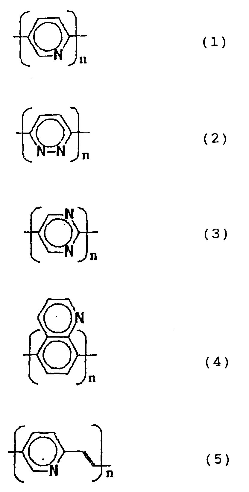

- For negative electrode
active material layer 3, there is used a material having a formal oxidation-reduction potential higher than that of negative electrodeactive material layer 2. Such a material may be selected from among quinone polymers, compounds of formulae (1) to (6), and polyaniline type polymers of the following formula.In the last case, compounds having different formal oxidation-reduction potentials may be obtained by properly selecting substituent groups R1. Substituent groups R1 each independently represent H or an electron-donating group. This electron-donating group is a substituent group having a Hammett substituent constant of 0 or less, and examples thereof include H, R2, NHCOR2, OR2, OH, NH2 and N(R2)2 in which R2 is an alkyl group of 1 to 10 carbon atoms and preferably a methyl or ethyl group.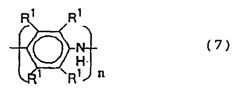
- Now, an example based on this embodiment (Example 1) is described below.
- First of all, particulate active carbon having a surface area of 2,000 cm2/g and a particle diameter of 10 µm was mixed with carbon serving as an electrically conductive filler, and then with 15 wt.% of polyvinylidene fluoride (with an average molecular weight of 1,000) serving as a binder resin. Moreover, butyl phthalyl butyl glycol as a plasticizer, 2-(2-butoxyethoxy)ethanol as a boiling point modifier, and N-methylpyrrolidone (NMP) as a solvent were added thereto.
- Using a doctor blade, the resulting slurry was spread on current collector sheets (made of butyl rubber and carbon) so as to form a film. The film so formed had a thickness of 50 µm. Thereafter, these sheets were cut into a predetermined shape and used as
current collectors 1. - Next, polypyridine used as the active material for the formation of a negative electrode
active material layer 2 was dissolved in formic acid at room temperature and its concentration was adjusted to 10 wt.%. Acurrent collector 1 was vacuum-impregnated with the polypyridine solution so prepared, and vacuum-dried at room temperature to form a negative electrodeactive material layer 2. The measurement of its dry weight revealed that the weight of the deposited polypyridine was 2.0 mg. The polypyridine layer so formed had a thickness of not greater than 5 µm on the basis of observations by SEM. - Subsequently, dimethoxypolyaniline of the formulawas dissolved in N-methylpyrrolidone (NMP) and its concentration was adjusted to 10 wt.%. Negative electrode

active material layer 2 formed oncurrent collector 1 was vacuum-impregnated with the dimethoxypolyaniline solution so prepared, and vacuum-dried at 40°C to form a negative electrodeactive material layer 3. The dry weight of the deposited dimethoxypolyaniline was 2.0 mg. The dimethoxypolyaniline layer formed on the polypyridine layer had a thickness of not greater than 5 µm on the basis of observations by SEM. - This electrode was doped by soaking it in a 1M aqueous solution of polyvinylsulfonic acid (PVSA) at 70°C for 6 hours. After completion of the doping, this electrode was washed with methanol, vacuum-dried at room temperature, and used as a negative electrode.
- In order to fabricate a positive electrode, methylpolyaniline of the formulaused as the active material for the formation of a positive electrode

active material layer 6 was dissolved in NMP and its concentration was adjusted to 10 wt.%. Anothercurrent collector 1 was vacuum-impregnated with the methylpolyaniline solution so prepared, and vacuum-dried at 40°C to form a positive electrodeactive material layer 6. The methylpolyaniline layer so formed had a thickness of not greater than 5 µm on the basis of observations by SEM. - This electrode was doped by soaking it in a 1M aqueous solution of polyvinylsulfonic acid at 70°C for 6 hours, and thus made insoluble in NMP. After completion of the doping, this electrode was washed with methanol and vacuum-dried at room temperature. The dry weight of the deposited methylpolyanlline was 2.0 mg.
- Subsequently, polyaniline of the formulawas dissolved in NMP and its concentration was adjusted to 10 wt.%. Positive electrode

active material layer 6 formed oncurrent collector 1 was vacuum-impregnated with the polyaniline solution so prepared, and vacuum-dried at 40°C to form a positive electrode active material layer 5. The dry weight of the deposited polyaniline was 2.0 mg. The polyaniline layer formed on the methylpolyaniline layer had a thickness of not greater than 5 µm on the basis of observations by SEM. - This electrode was doped by soaking it in a 1M aqueous solution of polyvinylsulfonic acid (PVSA) at 70°C for 6 hours. After completion of the doping, this electrode was washed with methanol, vacuum-dried at room temperature, and used as a positive electrode.
- Finally, a polymer secondary battery was constructed by arranging the positive and negative electrodes in opposed relationship so that a
separator 4 vacuum-impregnated with an electrolytic solution comprising a 6N aqueous solution of PVSA was interposed therebetween. - The completed polymer secondary battery was charged at a constant current of 34 µA (0.1C) and then discharged at a constant current of 34 µA (0.1C). Its theoretical capacity was assumed to be 172 mAh/g with consideration for the deactivation limit of polyaniline. As a result, the capacity in the voltage range of 1.0 to 0.2 V was 0.28 mAh and the rate of appearance of capacity had a very high value of 80%. Moreover, this battery could be quickly charged and discharged at 40 mA (120C). As to its cycle characteristics, the number of cycles which caused the capacity to decrease to 50% of the initial capacity was 10,000.
- Although a 6N aqueous solution of PVSA was used as the electrolytic solution in this example, the present invention is not limited thereto and there may be used any organic electrolytic solution. Moreover, although polyvinylidene fluoride was used as the binder resin, the present invention is not limited thereto and there may be used any other resin that is not corroded by the electrolytic solution.
- In the above-described construction, the materials used for negative electrode
active material layers active material layers 5, 6 constituting the negative and positive electrodes, respectively, cause oxidation-reduction reactions based on the same chemical species (i.e., hydrogen ion in Example 1), whereby the secondary battery can be charged or discharged. Active material layers 3 and 5 are formed of materials which, during charging, react easily with the chemical species (i.e., hydrogen ion in Example 1) required for oxidation-reduction reactions in the negative and positive electrodes, respectively (i.e., a material having a relatively high formal oxidation-reduction potential on the negative electrode side and a material having a relatively low formal oxidation-reduction potential on the positive electrode side). As a result, a reaction releasing the chemical species occurs readily in the positive electrode, and a reaction absorbing the chemical species occurs readily in the negative electrode. As the reactions proceed, the concentration of the chemical species required for the oxidation-reduction reactions inactive material layers active material layer 3, respectively, as compared with the concentration of the chemical species in the electrolytic solution or solid electrolyte. That is, the concentration of the chemical species required for the oxidation-reduction reactions at the active material layer interfaces is reduced at the interface between positive electrodeactive material layers 5 and 6 or raised at the interface between negative electrodeactive material layers active material layers - Furthermore, since the electrodes have a laminated structure in the present invention, the first electrode layers do not come into contact with the electrolytic solution or solid electrolyte. Consequently, they are not oxidatively degraded by oxygen present in the electrolytic solution or solid electrolyte region, resulting in an improvement in cycle characteristics.
- A second embodiment of the present invention is described below with reference to the accompanying drawings. Referring to FIG. 2, the electrode on the positive side has a single-layer structure consisting of a positive electrode active material layer 7 alone. Generally, positive electrode materials have a high reaction rate. Accordingly, when such a positive electrode material having a high reaction rate is used, a double-layer structure as has been described in connection with the first embodiment is not required and the positive electrode may have a single-layer structure. Moreover, since positive electrode materials are generally resistant to oxidation by oxygen present in the electrolytic solution or solid electrolyte region, the use of such a material can minimize a reduction in cycle characteristics.
- This embodiment makes it possible to decrease the number of steps required for the manufacture of batteries without reducing battery characteristics, and to reduce the thickness of the batteries.
- Now, an example based on this embodiment (Example 2) is described below.
- A negative electrode was formed in the same manner as described in Example 1. The positive electrode had a single-layer structure consisting of a positive electrode active material layer 7 alone. First of all, methylpolyaniline was dissolved in NMP and its concentration was adjusted to 10 wt.%. Then, a
current collector 1 was vacuum-impregnated with the methylpolyaniline solution so prepared and vacuum-dried at 40°C to form a positive electrode active material layer 7. The dry weight of the deposited methylpolyaniline was 2.0 mg. The methylpolyaniline layer so formed had a thickness of not greater than 5 µm on the basis of observations by SEM. - This positive electrode active material layer 7 was doped by soaking it in a 1M aqueous solution of PVSA at 70°C for 6 hours. After completion of the doping, the resulting electrode was washed with methanol, vacuum-dried at room temperature, and used as a positive electrode.
- Finally, a polymer secondary battery was constructed in the same manner as described in Example 1.
- The completed polymer secondary battery was charged at a constant current of 34 µA (0.1C) and then discharged at a constant current of 34 µA (0.1C). As a result, the capacity in the voltage range of 1.0 to 0.2 V was 0.28 mAh and the rate of appearance of capacity had a very high value of 80%. Moreover, this battery could be quickly charged and discharged at 40 mA (120C). As to its cycle characteristics, the number of cycles which caused the capacity to decrease to 50% of the initial capacity was 10,000.
- Although a 6N aqueous solution of PVSA was used as the electrolytic solution in this example, the present invention is not limited thereto and there may be used any organic electrolytic solution. Moreover, although polyvinylidene fluoride was used as the binder resin, the present invention is not limited thereto and there may be used any other resin that is not corroded by the electrolytic solution.
- A third embodiment of the present invention is described below with reference to the accompanying drawings. Referring to FIG. 3, the electrode on the positive side has a single-layer structure consisting of a positive electrode active material layer 7 alone. Generally, positive electrode materials have a high reaction rate. Accordingly, when such a positive electrode material having a high reaction rate is used, a double-layer structure as has been described in connection with the first embodiment is not required and the positive electrode may have a single-layer structure. Moreover, since positive electrode materials are generally resistant to oxidation by oxygen present in the electrolytic solution or solid electrolyte region, the use of such a material can minimize a reduction in cycle characteristics.
- In Examples 1 and 2, the difference in formal oxidation-reduction potential between negative electrode
active material layers active material layers 8 formed of polypyrimidine having a formal oxidation-reduction potential intermediate between those of negative electrodeactive material layers - In this embodiment, the oxidation-reduction reaction in negative electrode
active material layer 2 is further accelerated by reducing the potential difference with negative electrodeactive material layer 2. Consequently, the secondary battery constructed in accordance with this embodiment can be discharged at higher currents. - Now, an example based on this embodiment (Example 3) is described below.
- A negative electrode
active material layer 2 was formed in the same manner as described in Example 1. Thereafter, polypyrimidine used as the active material for the formation of a negative electrodeactive material layer 8 was dissolved in sulfuric acid and its concentration was adjusted to 10 wt.%. Negative electrodeactive material layer 2 formed oncurrent collector 1 was vacuum-impregnated with the polypyrimidine solution so prepared, and vacuum-dried at 40°C to form a negative electrodeactive material layer 8. After drying, this negative electrodeactive material layer 8 was washed with water until the washings became neutral, washed with methanol, and vacuum-dried at room temperature. The dry weight of the deposited polypyrimidine was 1.5 mg. The polypyrimidine layer so formed had a thickness of not greater than 4 µm on the basis of observations by SEM. - Subsequently, a negative electrode
active material layer 3 was formed according to the procedure described in Example 1. Thus, a negative electrode was fabricated. - Next, a positive electrode was fabricated by forming a positive electrode active material layer 7 of methylpolyaniline according to the procedure described in Example 2.
- Finally, a polymer secondary battery was constructed in the same manner as described in Example 1.
- The completed polymer secondary battery was charged at a constant current of 34 µA (0.1C) and then discharged at a constant current of 34 µA (0.1C). As a result, the capacity in the voltage range of 1.0 to 0.2 V was 0.3 mAh and the rate of appearance of capacity had a very high value of 85%. Moreover, this battery could be quickly charged and discharged at 50 mA (150C). As to its cycle characteristics, the number of cycles which caused the capacity to decrease to 50% of the initial capacity was 15,000.
- Although a 6N aqueous solution of PVSA was used as the electrolytic solution in this example, the present invention is not limited thereto and there may be used any organic electrolytic solution. Moreover, although polyvinylidene fluoride was used as the binder resin, the present invention is not limited thereto and there may be used any other resin that is not corroded by the electrolytic solution.
- FIG. 4 is a schematic cross-sectional view of a conventional polymer secondary battery. In this comparative example, both the negative electrode and the positive electrode have a single-layer structure consisting of a negative electrode
active material layer 9 alone and a positive electrode active material layer 7 alone, respectively. - The aforesaid conventional secondary battery was constructed in the following manner.
Current collectors 1 were made in the same manner as described in Example 1. Then, a negative electrodeactive material layer 9 consisting of polypyridine and a positive electrode active material layer 7 consisting of methylpolyaniline were formed and impregnated according to the procedures described in Example 1 to complete a polymer secondary battery. The weights of negative electrodeactive material layer 9 and positive electrode active material layer 7 were both 2.0 mg. - The conventional polymer secondary battery constructed in the above-described manner was charged at a constant current of 34 µA (0.1C) and then discharged at a constant current of 34 µA (0.1C). As a result, the capacity in the voltage range of 1.0 to 0.2 V was 0.01 mAh and the rate of appearance of capacity was 3%. Moreover, this battery could only be charged and discharged at a current of up to 1C. As to its cycle characteristics, the number of cycles which caused the capacity to decrease to 50% of the initial capacity was 50.
- The above-described results are summarized in Table 1, FIG. 5 and FIG. 6.
Rate of appearance of capacity (%) Quick charging and discharging (C) Cycle characteristics (number of cycles) Example 1 80 120 10,000 Example 2 80 120 10,000 Example 3 85 150 15,000 Comparative Example 3 1 50 - A first effect of the present invention is that a polymer secondary battery having a high rate of appearance of capacity and capable of quick charging and discharging can be provided. The reason for this is that, according to the construction of the present invention, the concentration of the chemical species required for oxidation-reduction reactions can be reduced in the vicinity of the electrode layer adjacent to the current collector of the positive electrode and raised in the vicinity of the electrode layer adjacent to the current collector of the negative electrode, and this facilitates the occurrence of oxidation-reduction reactions in the electrodes and thereby accelerates the reactions.
- A second effect of the present invention is that a secondary battery exhibiting excellent cycle characteristics can be provided. The reason for this is that, according to the construction of the present invention, the second electrode layer prevents the first electrode layer from coming into contact with oxygen dissolved in the electrolytic solution or oxygen present in the solid electrolyte region, and thereby protects the first electrode layer susceptible to oxidative degradation.
- The term "rate of appearance of capacity" as used throughout the specification means the ratio between the effective capacity of the battery and the theoretical capacity as calculated from the specific capacity of the active material and the weight of such active material. Thus, the rate of appearance of capacity may be expressed by the following formula
- R is the rate of appearance of capacity in %,
- Ceff is the effective capacity of the battery as measured by charging and discharging of the battery,
- Cspec is the theoretical specific capacity per unit weight of the active material of the positive or negative electrode, depending on which of the two active materials has the lower value of Cspec,
- W is the total weight of the active material having said lower value of Cspec.
-
Claims (6)
- A polymer secondary battery comprising a pair of current collectors and electrodes arranged in opposed relationship with an electrolytic solution-containing separator or a solid electrolyte interposed therebetween, said polymer secondary battery having a structure in which, with respect to one or both of the positive and negative electrodes, at least one layer of a material capable of causing an oxidation-reduction reaction based on the same chemical species is laminated to an active material layer constituting the electrode, the material used for said negative electrode having a formal oxidation-reduction potential higher than that of the active material layer adjacent to the current collector and the material used for said positive electrode having a formal oxidation-reduction potential lower than that of the active material layer adjacent to the current collector.
- A polymer secondary battery as claimed in claim 1 wherein said negative electrode comprises two or more active material layers each consisting of a polymer selected from among quinone polymers, nitrogen-containing heterocyclic compound polymers, nitrogen-containing condensed heterocyclic compound polymers and polyaniline type polymers.
- A polymer secondary battery as claimed in claim 2 wherein a first negative electrode active material layer adjacent to the current collector consists of a polymer selected from among nitrogen-containing heterocyclic compound polymers and nitrogen-containing condensed heterocyclic compound polymers, and a second negative electrode active material layer formed on the first negative electrode active material layer consists of a polymer selected from among quinone polymers, nitrogen-containing heterocyclic compound polymers, nitrogen-containing condensed heterocyclic compound polymers and polyaniline type polymers.
- A polymer secondary battery as claimed in claim 3 wherein the polyaniline type polymers are polymers of the general formulawhere each R1 independently represents a substituent group having a Hammett substituent constant of 0 or less.

- A polymer secondary battery as claimed in claims 2,3 wherein said negative electrode includes, between a first negative electrode active material layer adjacent to the current collector and a second negative electrode active material layer formed thereon, a third negative electrode active material layer having a formal oxidation-reduction potential which is higher than that of the first negative electrode active material layer and lower than that of the second negative electrode active material layer.
- A polymer secondary battery as claimed in claim 1 wherein said positive electrode comprises a positive electrode active material layer consisting of a polyaniline type polymer.
Applications Claiming Priority (3)
| Application Number | Priority Date | Filing Date | Title |
|---|---|---|---|
| JP29094397 | 1997-10-23 | ||
| JP09290943A JP3111945B2 (en) | 1997-10-23 | 1997-10-23 | Polymer secondary battery |
| JP290943/97 | 1997-10-23 |
Publications (2)
| Publication Number | Publication Date |
|---|---|
| EP0911894A1 true EP0911894A1 (en) | 1999-04-28 |
| EP0911894B1 EP0911894B1 (en) | 2001-04-11 |
Family
ID=17762504
Family Applications (1)
| Application Number | Title | Priority Date | Filing Date |
|---|---|---|---|
| EP98119870A Expired - Lifetime EP0911894B1 (en) | 1997-10-23 | 1998-10-20 | Polymer secondary batteries |
Country Status (4)
| Country | Link |
|---|---|
| US (1) | US6099989A (en) |
| EP (1) | EP0911894B1 (en) |
| JP (1) | JP3111945B2 (en) |
| DE (1) | DE69800689T2 (en) |
Cited By (3)
| Publication number | Priority date | Publication date | Assignee | Title |
|---|---|---|---|---|
| EP0987775A2 (en) * | 1998-09-04 | 2000-03-22 | NEC Corporation | Organic polymer battery electrode, secondary battery and method of manufacturing same |
| CN106654347A (en) * | 2016-12-27 | 2017-05-10 | 杨丽 | Lithium battery |
| EP3358667A4 (en) * | 2015-09-28 | 2018-12-05 | Panasonic Intellectual Property Management Co., Ltd. | Method for manufacturing electrochemical device, and electrochemical device |
Families Citing this family (9)
| Publication number | Priority date | Publication date | Assignee | Title |
|---|---|---|---|---|
| JP2943792B1 (en) * | 1998-04-03 | 1999-08-30 | 日本電気株式会社 | Proton conductive polymer battery and method for producing the same |
| JP2000223373A (en) * | 1999-02-03 | 2000-08-11 | Nec Corp | Polarizing electrode, manufacture thereof, electric double layer capacitor using the same and manufacture thereof |
| DE60036821T2 (en) * | 1999-12-10 | 2008-07-31 | Nitto Denko Corp., Ibaraki | FUEL CELL |
| JP3471304B2 (en) | 2000-09-18 | 2003-12-02 | Necトーキン株式会社 | Secondary battery and capacitor using indole compound |
| JP4508601B2 (en) * | 2002-11-08 | 2010-07-21 | 三洋電機株式会社 | Non-aqueous electrolyte battery |
| JP2010129279A (en) * | 2008-11-26 | 2010-06-10 | Denso Corp | Electrode for secondary battery and secondary battery |
| CN102544432A (en) * | 2010-12-13 | 2012-07-04 | 依诺特生物能量控股公司 | Positive electrode and battery with same |
| JP5677885B2 (en) * | 2011-04-18 | 2015-02-25 | 国立大学法人岩手大学 | Positive electrode for lithium secondary battery and lithium secondary battery |
| EP2876709A1 (en) * | 2013-11-22 | 2015-05-27 | Funai Electric Co., Ltd. | Lithium ion capacitor |
Citations (4)
| Publication number | Priority date | Publication date | Assignee | Title |
|---|---|---|---|---|
| JPS62195852A (en) * | 1986-02-24 | 1987-08-28 | Toyota Central Res & Dev Lab Inc | Manufacture of positive electrode for storage battery |
| JPS6472462A (en) * | 1987-09-11 | 1989-03-17 | Komatsu Mfg Co Ltd | Polyaniline cell using plastic collector electrode |
| US5002700A (en) * | 1988-08-30 | 1991-03-26 | Osaka Gas Company Limited | Permanently doped polyaniline and method thereof |
| US5183543A (en) * | 1985-05-15 | 1993-02-02 | Bridgestone Corporation | Polyanilines, process for the preparation thereof and cells using them |
Family Cites Families (7)
| Publication number | Priority date | Publication date | Assignee | Title |
|---|---|---|---|---|
| CA1268808A (en) * | 1985-07-23 | 1990-05-08 | Alan G. Macdiarmid | High capacity polyaniline electrodes |
| DE3607378A1 (en) * | 1986-03-06 | 1987-09-10 | Basf Ag | ELECTROCHEMICAL SECONDARY ELEMENT WITH AT LEAST ONE POLYMER ELECTRODE |
| JPS6336319A (en) * | 1986-07-30 | 1988-02-17 | Bridgestone Corp | Backup of ic memory |
| JPH02129851A (en) * | 1988-11-08 | 1990-05-17 | Mitsui Mining & Smelting Co Ltd | Secondary battery and electrode for secondary battery and manufacture thereof |
| JPH0362451A (en) * | 1989-04-06 | 1991-03-18 | Osaka Gas Co Ltd | Electrode of polyaniline polymer and preparation of polyaniline polymer |
| JP3492001B2 (en) * | 1995-01-11 | 2004-02-03 | 三菱重工業株式会社 | Battery electrode |
| JPH10261418A (en) * | 1997-03-18 | 1998-09-29 | Kyushu Electric Power Co Inc | Positive electrode material for lithium secondary battery |
-
1997
- 1997-10-23 JP JP09290943A patent/JP3111945B2/en not_active Expired - Fee Related
-
1998
- 1998-10-19 US US09/174,312 patent/US6099989A/en not_active Expired - Fee Related
- 1998-10-20 DE DE69800689T patent/DE69800689T2/en not_active Expired - Lifetime
- 1998-10-20 EP EP98119870A patent/EP0911894B1/en not_active Expired - Lifetime
Patent Citations (4)
| Publication number | Priority date | Publication date | Assignee | Title |
|---|---|---|---|---|
| US5183543A (en) * | 1985-05-15 | 1993-02-02 | Bridgestone Corporation | Polyanilines, process for the preparation thereof and cells using them |
| JPS62195852A (en) * | 1986-02-24 | 1987-08-28 | Toyota Central Res & Dev Lab Inc | Manufacture of positive electrode for storage battery |
| JPS6472462A (en) * | 1987-09-11 | 1989-03-17 | Komatsu Mfg Co Ltd | Polyaniline cell using plastic collector electrode |
| US5002700A (en) * | 1988-08-30 | 1991-03-26 | Osaka Gas Company Limited | Permanently doped polyaniline and method thereof |
Non-Patent Citations (3)
| Title |
|---|
| OYAMA N ET AL: "Organosulfur polymer batteries with high energy density", JOURNAL OF POWER SOURCES, vol. 68, no. 1, September 1997 (1997-09-01), pages 135-138, XP004100213 * |
| PATENT ABSTRACTS OF JAPAN vol. 012, no. 044 (E - 581) 9 February 1988 (1988-02-09) * |
| PATENT ABSTRACTS OF JAPAN vol. 013, no. 288 (E - 781) 30 June 1989 (1989-06-30) * |
Cited By (4)
| Publication number | Priority date | Publication date | Assignee | Title |
|---|---|---|---|---|
| EP0987775A2 (en) * | 1998-09-04 | 2000-03-22 | NEC Corporation | Organic polymer battery electrode, secondary battery and method of manufacturing same |
| EP0987775A3 (en) * | 1998-09-04 | 2004-12-08 | Nec Tokin Corporation | Organic polymer battery electrode, secondary battery and method of manufacturing same |
| EP3358667A4 (en) * | 2015-09-28 | 2018-12-05 | Panasonic Intellectual Property Management Co., Ltd. | Method for manufacturing electrochemical device, and electrochemical device |
| CN106654347A (en) * | 2016-12-27 | 2017-05-10 | 杨丽 | Lithium battery |
Also Published As
| Publication number | Publication date |
|---|---|
| JPH11126609A (en) | 1999-05-11 |
| JP3111945B2 (en) | 2000-11-27 |
| DE69800689T2 (en) | 2001-11-15 |
| DE69800689D1 (en) | 2001-05-17 |
| US6099989A (en) | 2000-08-08 |
| EP0911894B1 (en) | 2001-04-11 |
Similar Documents
| Publication | Publication Date | Title |
|---|---|---|
| US6413675B1 (en) | Multi layer electrolyte and cell using the same | |
| US6509116B1 (en) | Secondary battery and capacitor using indole polymeric compound | |
| JP3019326B2 (en) | Lithium secondary battery | |
| JP3168962B2 (en) | Battery | |
| US6004698A (en) | Solid polymer electrolyte electrochemical storage cell containing a redox shuttle additive for overcharge protection | |
| US7082027B2 (en) | Proton-conducting electric double layer capacitor using electrolytic solution | |
| EP3467907B1 (en) | Method for manufacturing electrode including polymer electrolyte and electrode obtained thereby | |
| EP0616381A1 (en) | Lithium-based polymer electrolyte electrochemical cell | |
| US6899974B2 (en) | Secondary battery of proton conductive polymer | |
| EP0911894B1 (en) | Polymer secondary batteries | |
| JP3708426B2 (en) | Proton conducting polymer secondary battery | |
| JP4088755B2 (en) | Nonaqueous electrolyte secondary battery | |
| KR100418845B1 (en) | Secondary Battery and Capacitor Utilizing Indole Compounds | |
| KR100586823B1 (en) | Electrode for Electrochemical Cell and Electrochemical Cell therewith | |
| US20080226985A1 (en) | Electrochemical cell | |
| US20020114128A1 (en) | Redox supercapacitor and manufacturing method thereof | |
| JP4530133B2 (en) | Power storage device | |
| KR100540701B1 (en) | Electrochemical cell | |
| US7205071B2 (en) | Secondary battery and capacitor utilizing indole compounds | |
| JP2004127920A (en) | Cell electrode and electrochemical cell using it | |
| US6678150B2 (en) | Capacitor element using quinoxaline compound | |
| KR102598513B1 (en) | Binder resin for electrode of secondary battery, anode for secondary battery and secondary battery | |
| JP2977600B2 (en) | Lead storage battery | |
| JP2004342593A (en) | Electrochemical cell |
Legal Events
| Date | Code | Title | Description |
|---|---|---|---|
| PUAI | Public reference made under article 153(3) epc to a published international application that has entered the european phase |
Free format text: ORIGINAL CODE: 0009012 |
|
| AK | Designated contracting states |
Kind code of ref document: A1 Designated state(s): DE FR GB |
|
| AX | Request for extension of the european patent |
Free format text: AL;LT;LV;MK;RO;SI |
|
| 17P | Request for examination filed |
Effective date: 19990309 |
|
| AKX | Designation fees paid |
Free format text: DE FR GB |
|
| GRAG | Despatch of communication of intention to grant |
Free format text: ORIGINAL CODE: EPIDOS AGRA |
|
| 17Q | First examination report despatched |
Effective date: 20000602 |
|
| GRAG | Despatch of communication of intention to grant |
Free format text: ORIGINAL CODE: EPIDOS AGRA |
|
| GRAH | Despatch of communication of intention to grant a patent |
Free format text: ORIGINAL CODE: EPIDOS IGRA |
|
| GRAH | Despatch of communication of intention to grant a patent |
Free format text: ORIGINAL CODE: EPIDOS IGRA |
|
| GRAA | (expected) grant |
Free format text: ORIGINAL CODE: 0009210 |
|
| AK | Designated contracting states |
Kind code of ref document: B1 Designated state(s): DE FR GB |
|
| REF | Corresponds to: |
Ref document number: 69800689 Country of ref document: DE Date of ref document: 20010517 |
|
| ET | Fr: translation filed | ||
| REG | Reference to a national code |
Ref country code: GB Ref legal event code: IF02 |
|
| PLBE | No opposition filed within time limit |
Free format text: ORIGINAL CODE: 0009261 |
|
| STAA | Information on the status of an ep patent application or granted ep patent |
Free format text: STATUS: NO OPPOSITION FILED WITHIN TIME LIMIT |
|
| 26N | No opposition filed | ||
| REG | Reference to a national code |
Ref country code: GB Ref legal event code: 732E |
|
| REG | Reference to a national code |
Ref country code: FR Ref legal event code: TP |
|
| PGFP | Annual fee paid to national office [announced via postgrant information from national office to epo] |
Ref country code: DE Payment date: 20091015 Year of fee payment: 12 |
|
| PGFP | Annual fee paid to national office [announced via postgrant information from national office to epo] |
Ref country code: GB Payment date: 20091014 Year of fee payment: 12 Ref country code: FR Payment date: 20091029 Year of fee payment: 12 |
|
| GBPC | Gb: european patent ceased through non-payment of renewal fee |
Effective date: 20101020 |
|
| PG25 | Lapsed in a contracting state [announced via postgrant information from national office to epo] |
Ref country code: FR Free format text: LAPSE BECAUSE OF NON-PAYMENT OF DUE FEES Effective date: 20101102 |
|
| REG | Reference to a national code |
Ref country code: FR Ref legal event code: ST Effective date: 20110630 |
|
| PG25 | Lapsed in a contracting state [announced via postgrant information from national office to epo] |
Ref country code: GB Free format text: LAPSE BECAUSE OF NON-PAYMENT OF DUE FEES Effective date: 20101020 |
|
| REG | Reference to a national code |
Ref country code: DE Ref legal event code: R119 Ref document number: 69800689 Country of ref document: DE Effective date: 20110502 |
|
| PG25 | Lapsed in a contracting state [announced via postgrant information from national office to epo] |
Ref country code: DE Free format text: LAPSE BECAUSE OF NON-PAYMENT OF DUE FEES Effective date: 20110502 |