EP0914067B1 - Ultrasonic interlock - Google Patents
Ultrasonic interlock Download PDFInfo
- Publication number
- EP0914067B1 EP0914067B1 EP98908572A EP98908572A EP0914067B1 EP 0914067 B1 EP0914067 B1 EP 0914067B1 EP 98908572 A EP98908572 A EP 98908572A EP 98908572 A EP98908572 A EP 98908572A EP 0914067 B1 EP0914067 B1 EP 0914067B1
- Authority
- EP
- European Patent Office
- Prior art keywords
- transmission component
- assembly
- ultrasonic
- end effector
- obturator
- Prior art date
- Legal status (The legal status is an assumption and is not a legal conclusion. Google has not performed a legal analysis and makes no representation as to the accuracy of the status listed.)
- Expired - Lifetime
Links
- 230000005540 biological transmission Effects 0.000 claims description 75
- 239000012636 effector Substances 0.000 claims description 56
- 230000004044 response Effects 0.000 claims description 3
- 210000001519 tissue Anatomy 0.000 description 24
- 239000000463 material Substances 0.000 description 14
- 230000007246 mechanism Effects 0.000 description 14
- 230000035515 penetration Effects 0.000 description 13
- 230000026683 transduction Effects 0.000 description 5
- 238000010361 transduction Methods 0.000 description 5
- 239000004812 Fluorinated ethylene propylene Substances 0.000 description 4
- 230000000694 effects Effects 0.000 description 4
- 229920009441 perflouroethylene propylene Polymers 0.000 description 4
- -1 polypropylene Polymers 0.000 description 4
- 229920001296 polysiloxane Polymers 0.000 description 4
- 229920001343 polytetrafluoroethylene Polymers 0.000 description 4
- 239000004810 polytetrafluoroethylene Substances 0.000 description 4
- 230000015271 coagulation Effects 0.000 description 3
- 238000005345 coagulation Methods 0.000 description 3
- 230000008878 coupling Effects 0.000 description 3
- 238000010168 coupling process Methods 0.000 description 3
- 238000005859 coupling reaction Methods 0.000 description 3
- 238000001514 detection method Methods 0.000 description 3
- 208000014674 injury Diseases 0.000 description 3
- 238000000034 method Methods 0.000 description 3
- 102000004169 proteins and genes Human genes 0.000 description 3
- 108090000623 proteins and genes Proteins 0.000 description 3
- 239000007787 solid Substances 0.000 description 3
- 238000001356 surgical procedure Methods 0.000 description 3
- 230000008733 trauma Effects 0.000 description 3
- 229910000838 Al alloy Inorganic materials 0.000 description 2
- 229910001069 Ti alloy Inorganic materials 0.000 description 2
- 229910000883 Ti6Al4V Inorganic materials 0.000 description 2
- 229920004738 ULTEM® Polymers 0.000 description 2
- 210000004204 blood vessel Anatomy 0.000 description 2
- 210000004027 cell Anatomy 0.000 description 2
- 230000006835 compression Effects 0.000 description 2
- 238000007906 compression Methods 0.000 description 2
- 230000000994 depressogenic effect Effects 0.000 description 2
- 238000006073 displacement reaction Methods 0.000 description 2
- 238000012976 endoscopic surgical procedure Methods 0.000 description 2
- 230000008713 feedback mechanism Effects 0.000 description 2
- 238000003780 insertion Methods 0.000 description 2
- 230000037431 insertion Effects 0.000 description 2
- 238000002955 isolation Methods 0.000 description 2
- 238000012986 modification Methods 0.000 description 2
- 230000004048 modification Effects 0.000 description 2
- 239000004033 plastic Substances 0.000 description 2
- 229920003023 plastic Polymers 0.000 description 2
- 229940058401 polytetrafluoroethylene Drugs 0.000 description 2
- 239000010935 stainless steel Substances 0.000 description 2
- 229910001220 stainless steel Inorganic materials 0.000 description 2
- 102000008186 Collagen Human genes 0.000 description 1
- 108010035532 Collagen Proteins 0.000 description 1
- 102000008934 Muscle Proteins Human genes 0.000 description 1
- 108010074084 Muscle Proteins Proteins 0.000 description 1
- 239000004743 Polypropylene Substances 0.000 description 1
- 229910000831 Steel Inorganic materials 0.000 description 1
- 241000282887 Suidae Species 0.000 description 1
- RTAQQCXQSZGOHL-UHFFFAOYSA-N Titanium Chemical compound [Ti] RTAQQCXQSZGOHL-UHFFFAOYSA-N 0.000 description 1
- 238000012084 abdominal surgery Methods 0.000 description 1
- 210000003815 abdominal wall Anatomy 0.000 description 1
- 230000003213 activating effect Effects 0.000 description 1
- 230000004913 activation Effects 0.000 description 1
- 229910052782 aluminium Inorganic materials 0.000 description 1
- XAGFODPZIPBFFR-UHFFFAOYSA-N aluminium Chemical compound [Al] XAGFODPZIPBFFR-UHFFFAOYSA-N 0.000 description 1
- 230000000712 assembly Effects 0.000 description 1
- 238000000429 assembly Methods 0.000 description 1
- 230000015572 biosynthetic process Effects 0.000 description 1
- 230000001413 cellular effect Effects 0.000 description 1
- 210000003850 cellular structure Anatomy 0.000 description 1
- 239000000919 ceramic Substances 0.000 description 1
- 230000008859 change Effects 0.000 description 1
- 229920001436 collagen Polymers 0.000 description 1
- 238000010276 construction Methods 0.000 description 1
- 239000013078 crystal Substances 0.000 description 1
- NKZSPGSOXYXWQA-UHFFFAOYSA-N dioxido(oxo)titanium;lead(2+) Chemical compound [Pb+2].[O-][Ti]([O-])=O NKZSPGSOXYXWQA-UHFFFAOYSA-N 0.000 description 1
- 238000004945 emulsification Methods 0.000 description 1
- 230000023597 hemostasis Effects 0.000 description 1
- 229920005669 high impact polystyrene Polymers 0.000 description 1
- 239000004797 high-impact polystyrene Substances 0.000 description 1
- 229910052739 hydrogen Inorganic materials 0.000 description 1
- 239000001257 hydrogen Substances 0.000 description 1
- 230000001151 other effect Effects 0.000 description 1
- 210000003200 peritoneal cavity Anatomy 0.000 description 1
- 229920001155 polypropylene Polymers 0.000 description 1
- 230000002035 prolonged effect Effects 0.000 description 1
- 230000000087 stabilizing effect Effects 0.000 description 1
- 239000010959 steel Substances 0.000 description 1
- 238000004381 surface treatment Methods 0.000 description 1
- 229910052719 titanium Inorganic materials 0.000 description 1
- 239000010936 titanium Substances 0.000 description 1
- 230000001960 triggered effect Effects 0.000 description 1
Images


Classifications
-
- A—HUMAN NECESSITIES
- A61—MEDICAL OR VETERINARY SCIENCE; HYGIENE
- A61B—DIAGNOSIS; SURGERY; IDENTIFICATION
- A61B17/00—Surgical instruments, devices or methods, e.g. tourniquets
- A61B17/34—Trocars; Puncturing needles
- A61B17/3476—Powered trocars, e.g. electrosurgical cutting, lasers, powered knives
-
- A—HUMAN NECESSITIES
- A61—MEDICAL OR VETERINARY SCIENCE; HYGIENE
- A61B—DIAGNOSIS; SURGERY; IDENTIFICATION
- A61B17/00—Surgical instruments, devices or methods, e.g. tourniquets
- A61B17/32—Surgical cutting instruments
- A61B17/320068—Surgical cutting instruments using mechanical vibrations, e.g. ultrasonic
- A61B2017/320069—Surgical cutting instruments using mechanical vibrations, e.g. ultrasonic for ablating tissue
-
- A—HUMAN NECESSITIES
- A61—MEDICAL OR VETERINARY SCIENCE; HYGIENE
- A61B—DIAGNOSIS; SURGERY; IDENTIFICATION
- A61B17/00—Surgical instruments, devices or methods, e.g. tourniquets
- A61B17/32—Surgical cutting instruments
- A61B17/320068—Surgical cutting instruments using mechanical vibrations, e.g. ultrasonic
- A61B2017/320088—Surgical cutting instruments using mechanical vibrations, e.g. ultrasonic with acoustic insulation, e.g. elements for damping vibrations between horn and surrounding sheath
-
- A—HUMAN NECESSITIES
- A61—MEDICAL OR VETERINARY SCIENCE; HYGIENE
- A61B—DIAGNOSIS; SURGERY; IDENTIFICATION
- A61B17/00—Surgical instruments, devices or methods, e.g. tourniquets
- A61B17/32—Surgical cutting instruments
- A61B17/320068—Surgical cutting instruments using mechanical vibrations, e.g. ultrasonic
- A61B2017/320089—Surgical cutting instruments using mechanical vibrations, e.g. ultrasonic node location
Definitions
- the present invention relates generally to an ultrasonic device, and more particularly to an ultrasonic interlock or braking mechanism that can dampen the ultrasonic vibration of a transmission component.
- a trocar assembly is typically employed for effecting penetration of the wall of a body cavity of the patient.
- a typical trocar assembly includes an outer tubular cannula, and an inner tissue-piercing obturator having a puncturing tip.
- the trocar assembly is positioned so that the obturator can be advanced to form an opening in the wall of the body cavity with the puncturing tip, and the cannula thereafter inserted through the opening.
- the obturator is then removed from within the cannula, with the cannula thereafter providing access for insertion of surgical instruments and other devices related to the surgical procedure to be performed.
- trocar assemblies have a retractable or removable shield that can cover the puncturing tip of the obturator, thus covering the tissue-piercing portion of the assembly.
- the shield can be retracted to expose the puncturing tip to pierce the wall of the body cavity. Once the body cavity has been pierced, the shield re-covers the puncturing tip of the obturator. For example, in abdominal surgery, when the peritoneal cavity is reached, the shield covers the puncturing tip of the obturator.
- ultrasonic surgical instruments are also becoming increasingly widespread by virtue of the unique performance characteristics of such devices.
- such devices can provide substantially simultaneous cutting of tissue and hemostasis, again desirably minimizing patient trauma.
- U.S. Patent No. 5,449,370 discloses an ultrasonic trocar assembly including an ultrasonic obturator configured to effect ultrasonic penetration of the wall of a body cavity for subsequent introduction of a tubular cannula of the trocar assembly.
- the obturator of the trocar assembly is provided with a blunt or rounded tip for minimizing patient trauma attendant to penetration of the body cavity.
- a feedback mechanism shuts off or reduces the ultrasonic energy delivered to the obturator.
- the present invention is directed to an interlock or braking mechanism that mechanically dampens the ultrasonic energy delivered to a transmission component.
- An ultrasonic interlock embodying the principles of the present invention is provided to mechanically dampen the vibration of a transmission component.
- the interlock engages the periphery of a transmission component to dampen, arrest or reduce the vibration of the transmission component.
- a force is applied to the transmission component to prevent the ultrasonic energy from being transmitted through the transmission component.
- the interlock can also engage the transmission component to prevent inadvertent delivery of ultrasonic energy.
- the interlock may be utilized on any suitable ultrasonic device or ultrasonic surgical device, such as, for example, an ultrasonic scalpel and an ultrasonic trocar.
- An ultrasonic surgical device in accordance with the present invention includes a transducer assembly adapted to vibrate at an ultrasonic frequency in response to electrical energy.
- a transmission component is adapted to receive ultrasonic vibration from the transducer assembly and to transmit the ultrasonic vibration from a first end to a second end.
- a braking device is configured to apply a force to the outer surface of the transmission component to dampen the ultrasonic vibration being transmitted from the first end of the transmission rod to the second end of the transmission rod.
- a method which may be applied with the described device includes the steps of providing an ultrasonic trocar obturator having an ultrasonic waveguide including an end effector at a distal end thereof, positioning the trocar obturator within a trocar cannula, positioning the trocar obturator in contact with a wall of said body cavity, and ultrasonicly vibrating the end effector to create a penetration opening.
- the method also includes the steps of advancing the ultrasonic obturator into said penetration opening, detecting when penetration has been completed, and applying a braking member to the obturator to dampen the ultrasonic vibration of the end effector and advancing the trocar cannula into the penetration opening.
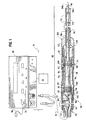
- the surgical system 10 generally includes a generator 30, a handpiece assembly 50, an acoustic or transmission assembly 80, and an interlock or braking mechanism 130.
- the generator 30 sends an electrical signal through a cable 32 at a selected amplitude, frequency, and phase determined by a control system of the generator 30.
- the signal causes one or more piezoelectric elements of the acoustic assembly 80 to expand and contract, thereby converting the electrical energy into mechanical motion.
- the mechanical motion results in longitudinal waves of ultrasonic energy that propagate through the acoustic assembly 80 in an acoustic standing wave to vibrate the acoustic assembly 80 at a selected frequency and amplitude.
- An end effector 88 at the distal end of the acoustic assembly 80 is placed in contact with tissue of the patient to transfer the ultrasonic energy to the tissue.
- the cells of the tissue in contact with the end effector 88 of the acoustic assembly 80 will move with the end effector 88 and vibrate.
- the end effector 88 couples with the tissue, thermal energy or heat is generated as a result of internal cellular friction within the tissue.
- the heat is sufficient to break protein hydrogen bonds, causing the highly structured protein (i.e., collagen and muscle protein) to denature (i.e., become less organized).
- the proteins are denatured, a sticky coagulum forms to seal or coagulate small blood vessels when the coagulum is below 100°C. Deep coagulation of larger blood vessels results when the effect is prolonged.
- the transfer of the ultrasonic energy to the tissue causes other effects including mechanical tearing, cutting, cavitation cell disruption, and emulsification.
- the amount of cutting as well as the degree of coagulation obtained varies with the vibrational amplitude of the end effector 88, the amount of pressure applied by the user, and the sharpness of the end effector 88.
- the end effector 88 of the acoustic assembly 80 in the surgical system 10 tends to focus the vibrational energy of the system 10 onto tissue in contact with the end effector 88, intensifying and localizing thermal and mechanical energy delivery.
- the generator 30 includes a control system integral to the generator 30, a power switch 34, and a triggering mechanism 36.
- the power switch 34 controls the electrical power to the generator 30, and when activated by the triggering mechanism 36, the generator 30 provides energy to drive the acoustic assembly 80 of the surgical system 10 at a predetermined frequency and to drive the end effector 88 at a predetermined vibrational amplitude level.
- the generator 30 may drive or excite the acoustic assembly 80 at any suitable resonant frequency of the acoustic assembly 80.
- a phase locked loop in the control system of the generator 30 monitors feedback from the acoustic assembly 80.
- the phase lock loop adjusts the frequency of the electrical energy sent by the generator 30 to match a preselected harmonic frequency of the acoustic assembly 80.
- a second feedback loop in the control system maintains the electrical current supplied to the acoustic assembly 80 at a preselected constant level in order to achieve substantially constant vibrational amplitude at the end effector 88 of the acoustic assembly 80.
- the electrical signal supplied to the acoustic assembly 80 will cause the distal end to vibrate longitudinally in the range of, for example, approximately 20 kHz to 100 kHz, and preferably in the range of about 54 kHz to 56 kHz, and most preferably at about 55.5 kHz.
- the amplitude of the acoustic vibrations at the end effector 88 may be controlled by, for example, controlling the amplitude of the electrical signal applied to the transducer assembly 82 of the acoustic assembly 80 by the generator 30.
- the triggering mechanism 36 of the generator 30 allows a user to activate the generator 30 so that electrical energy may be continuously supplied to the acoustic assembly 80.
- the triggering mechanism 36 preferably comprises a foot activating switch that is detachably coupled or attached to the generator 30 by a cable or cord.
- a hand switch may be incorporated in the handpiece assembly 50 to allow the generator 30 to be activated by a user.
- the generator 30 also has a power line 38 for insertion in an electrosurgical unit or conventional electrical outlet. It is contemplated that the generator 30 may also be powered by a direct current (DC) source, such as a battery.
- the generator 30 may be any suitable generator, such as Model No. GENO1, available from Ethicon Endo-Surgery, Inc.
- the handpiece assembly 50 includes a multi-piece housing or outer casing 52 adapted to isolate the operator from the vibrations of the acoustic assembly 80.
- the housing 52 is preferably cylindrically shaped and is adapted to be held by a user in a conventional manner, but may be any suitable shape and size which allows it to be grasped by the user. While a multi-piece housing 52 is illustrated, the housing 52 may comprise a single or unitary component.
- the housing 52 of the handpiece assembly 50 is preferably constructed from a durable plastic, such as Ultem®. It is also contemplated that the housing 52 may be made from a variety of materials including other plastics (i.e. high impact polystyrene or polypropylene).
- a suitable handpiece assembly 50 is Model No. HP050, available from Ethicon Endo-Surgery, Inc.
- the handpiece assembly 50 generally includes a proximal end 54, a distal end 56, and centrally disposed axial opening or cavity 58 extending longitudinally therein.
- the distal end 56 of the handpiece assembly 50 includes an opening 60 configured to allow the acoustic assembly 80 of the surgical system 10 to extend therethrough, and the proximal end 54 of the handpiece assembly 50 is coupled to the generator 30 by a cable 32.
- the cable 32 may include ducts or vents 62 to allow air to be introduced into the handpiece assembly 50 to cool the transducer assembly 82 of the acoustic assembly 80.
- the acoustic assembly 80 generally includes a transducer stack or assembly 82 and a transmission component.
- the transmission component may include a mounting device 84, a transmission rod or waveguide 86, and an end effector or applicator 88.
- the transducer assembly 82, mounting device 84, transmission rod 86, and the end effector 88 are preferably acoustically tuned such that the length of each component is an integral number of one-half system wavelengths (n ⁇ /2) where the system wavelength ⁇ is the wavelength of a preselected or operating longitudinal vibration frequency f of the acoustic assembly 80.
- the acoustic assembly 80 may incorporate any suitable arrangement of acoustic elements.
- the acoustic assembly 80 may comprise a transducer assembly and an end effector (i.e., the acoustic assembly 80 may be configured without a mounting device and a transmission rod).
- the transducer assembly 82 of the acoustic assembly 80 converts the electrical signal from the generator 30 into mechanical energy that results in longitudinal vibratory motion of the end effector 88 at ultrasonic frequencies.
- a vibratory motion standing wave is generated through the acoustic assembly 80.
- the amplitude of the vibratory motion at any point along the acoustic assembly 80 depends on the location along the acoustic assembly 80 at which the vibratory motion is measured.
- a minimum or zero crossing in the vibratory motion standing wave is generally referred to as a node (i.e., where axial motion is usually minimal and radial motion is usually small), and an absolute value maximum or peak in the standing wave is generally referred to as an antinode.
- the distance between an antinode and its nearest node is one-quarter wavelength ( ⁇ /4).
- the transducer assembly 82 of the acoustic assembly 80 which is known as a "Langevin stack" generally includes a transduction portion 90, a first resonator 92, and a second resonator 94.
- the transducer assembly 82 is preferably an integral number of one-half system wavelengths (n ⁇ /2) in length. It is to be understood that the present invention may be alternatively configured to include a transducer assembly comprising a magnetostrictive, electromagnetic or electrostatic transducer.
- the distal end of the first resonator 92 is connected to the proximal end of transduction section 90, and the proximal end of the second resonator 94 is connected to the distal end of transduction portion 90.
- the first and second resonators 92 and 94 are preferably fabricated from titanium, aluminum, steel, or any other suitable material.
- the first and second resonators 92 and 94 have a length determined by a number of variables, including the thickness of the transduction section 90, the density and modulus of elasticity of material used in the resonators 92 and 94, and the fundamental frequency of the transducer assembly 82.
- the second resonator 94 may be tapered inwardly from its proximal end to its distal end to amplify the ultrasonic vibration amplitude.
- the transduction portion 90 of the transducer assembly 82 preferably comprises a piezoelectric section of alternating positive electrodes 96 and negative electrodes 98, with piezoelectric elements 100 alternating between the electrodes 96 and 98.
- the piezoelectric elements 100 may be fabricated from any suitable material, such as, for example, lead zirconate-titante, lead meta-niobate, lead titanate, or ceramic piezoelectric crystal material.
- Each of the positive electrodes 96, negative electrodes 98, and piezoelectric elements 100 may have a bore extending through the center.
- the positive and negative electrodes 96 and 98 are electrically coupled to a wires 102 and 104, respectfully. Wires 102 and 104 transmit electrical signal from the generator 30 to electrodes 96 and 98.
- the piezoelectric elements 100 are held in compression between the first and second resonators 92 and 94 by a bolt 106.
- the bolt 106 preferably has a head, a shank, and a threaded distal end.
- the bolt 106 is inserted from the proximal end of the first resonator 92 through the bores of the first resonator 92, the electrodes 96 and 98, and piezoelectric elements 100.
- the threaded distal end of the bolt 106 is screwed into a threaded bore in the proximal end of second resonator 94.
- the piezoelectric elements 100 are energized in response to the electrical signal supplied from the generator 30 to produce an acoustic standing wave in the acoustic assembly 80.
- the electrical signal causes disturbances in the piezoelectric elements 100 in the form of repeated small displacements resulting in large compression forces within the material.
- the repeated small displacements cause the piezoelectric elements 100 to expand and contract in a continuous manner along the axis of the voltage gradient, producing high frequency longitudinal waves of ultrasonic energy.
- the ultrasonic energy is transmitted through the acoustic assembly 80 to the end effector 88.
- the mounting device 84 of the acoustic assembly 80 has a proximal end, a distal end, and may have a length substantially equal to an integral number of one-half system wavelengths.
- the proximal end of the mounting device 84 is preferably axially aligned and coupled to the distal end of the second resonator 94 by an internal threaded connection near an antinode.
- the term “near” is defined as "exactly at” or "in close proximity to”.
- the mounting device 84 may be attached to the second resonator 94 by any suitable means, and that the second resonator 94 and mounting device 84 may be formed as a single or unitary component.
- the mounting device 84 is connected or mounted to the housing 52 of the handpiece assembly 50 near a node.
- the mounting device 84 may include an integral ring 108 disposed around its periphery.
- the integral ring 108 is preferably disposed in an annular groove 110 formed in the housing 52 of the handpiece assembly 50 to mount the mounting device 84 to the housing 58.
- a compliant member or material 112 such as a pair of silicone O-rings attached by stand-offs, may be placed between the annular groove 110 of the housing 52 and the integral ring 108 of the mounting device 84 to reduce or prevent ultrasonic vibration from being transmitted from the mounting device 84 to the housing 52.
- the mounting device 84 may be secured in a predetermined axial position by a plurality of pins 114, preferably four.
- the pins 114 are disposed in a longitudinal direction 90 degrees apart from each other around the outer periphery of the mounting device 84.
- the pins 114 are coupled to the housing 52 of the handpiece assembly 50 and are disposed through notches in the integral ring 108 of the mounting device 84.
- the pins 114 are preferably fabricated from stainless steel.
- the mounting device 84 is preferably configured to amplify the ultrasonic vibration amplitude that is transmitted through the acoustic assembly 80 to the distal end of the end effector 88.
- the mounting device 84 comprises a solid, tapered horn. As ultrasonic energy is transmitted through the mounting device 84, the velocity of the acoustic wave transmitted through the mounting device 84 is amplified. It is contemplated that the mounting device 84 may be any suitable shape, such as a stepped horn, a conical horn, an exponential horn, or the like.
- the distal end of the mounting device 84 is coupled to the proximal end of the transmission rod 86. It is contemplated that the transmission rod 86 be attached to the mounting device 84 by any suitable means, such as, for example, an internal threaded connection.
- the mounting device 84 is preferably coupled to the transmission rod 86 near an antinode.
- the transmission rod 86 may, for example, have a length substantially equal to an integer number of one-half system wavelengths (n ⁇ /2).
- the transmission rod 86 may be preferably fabricated from a solid core shaft constructed out of material which propagates ultrasonic energy efficiently, such as titanium alloy (i.e., Ti-6Al-4V) or an aluminum alloy. It is contemplated that the transmission rod 86 may be fabricated from any suitable material.
- the transmission rod 86 may also amplify the mechanical vibrations transmitted through the transmission rod 86 to the end effector 88 as is well known in the art.
- the transmission rod 86 includes stabilizing silicone rings or compliant supports 116 positioned at a plurality of nodes.
- the silicone rings 116 dampen undesirable vibration and isolate the ultrasonic energy from a removable sheath 120 assuring the flow of ultrasonic energy in a longitudinal direction to the distal end of the end effector 88 with maximum efficiency.
- the removable sheath 120 is coupled to the distal end 56 of the handpiece assembly 50.
- the sheath 120 generally includes an adapter or nose cone 122 and an elongated tubular member 124.
- the elongated tubular member 124 extends from the adapter 122 and has an opening extending longitudinally therethrough.
- the sheath 120 may be threaded or snapped onto the distal end of the housing 52.
- the transmission rod 86 of the acoustic assembly 80 extends through the opening of the tubular member 124 and, the silicone rings 116 isolate the transmission rod 86 from the tubular member 124.
- the adapter 122 of the sheath 120 is preferably constructed from Ultem®, and the tubular member 124 is fabricated from stainless steel.
- the transmission rod 86 may have polymeric material that surrounds the transmission rod 86 to isolate it from outside contact.
- the distal end of the transmission rod 86 may be coupled to the proximal end of the end effector 88 by an internal threaded connection, preferably at or near an antinode. It is contemplated that the end effector 88 may be attached to the transmission rod 86 by any suitable means, such as a welded joint or the like. Although the end effector 88 may be detachable from the transmission rod 86, it is also contemplated that the end effector 88 and transmission rod 86 may be formed as a single unit.
- the end effector 88 may have a distal region 88b having a smaller cross-section area than a proximal region 88a thereof, thereby forming a vibrational amplitude step-up junction.
- the step-up junction acts as velocity transformer as known in the art, increasing the magnitude of the ultrasonic vibration transmitted from the proximal region 88a to the distal region 88b of the end effector 88.
- the end effector 88 preferably has a length substantially equal to an integral multiple of one-half system wavelengths (n ⁇ /2).
- the end effector 88 is disposed at an antinode in order to produce the maximum longitudinal deflection of the distal end.
- the distal end of the end effector 88 is configured to move longitudinally in the range of, for example, approximately 10 to 500 microns peak-to-peak, and preferably in the range of about 30 to 100 microns at a predetermined vibrational frequency, and most preferably at about 90 microns.
- the end effector 88 is preferably made from a solid core shaft constructed of material which propagates ultrasonic energy, such as a titanium alloy (i.e., Ti-6Al-4V) or an aluminum alloy. It will be recognized that the end effector 88 may be fabricated from other suitable materials. It is also contemplated that the end effector 88 may have a surface treatment to improve the delivery of energy and desired tissue effect. For example, the end effector 88 may be micro-finished, coated, plated, etched, grit-blasted, roughened or scored to enhance coagulation in tissue. Additionally, the end effector 88 may be sharpened or shaped to enhance its energy transmission characteristics. For example, the end effector 88 may be blade shaped, hook shaped, or ball shaped.
- the interlock 130 is preferably positioned near the proximal end of the transmission member 86. It is contemplated that the interlock 130 may be positioned at any suitable position along the acoustic assembly 80. For example and without limitation, the interlock 130 may be positioned to contact the transducer assembly 82, the mounting device 84, or the end effector 88. It will also be recognized that a plurality of interlocks may be positioned along the acoustic assembly.
- the interlock 130 of the surgical system 10 may be coupled to or incorporated into the handpiece assembly or the removable sheath as would be recognized by those skilled in the art.
- the interlock 130 includes a housing 132 and braking members 134a and 134b.
- the braking member 134a and 134b are preferably mounted on opposing sides of the transmission rod 86.
- the interlock 130 may have any suitable number of braking members 134a and 134b, (i.e. 1 to 6) and may be mounted in any suitable arrangement to engage the transmission rod 86.
- the interlock 130 may be moved manually or automatically.
- the interlock 130 may be forced against the acoustical assembly when a user manually depresses the braking members 134a and 134b to dampen, reduce and/or arrest ultrasonic energy.
- the interlock 130 may be activated to dampen, reduce and/or arrest the ultrasonic energy when the end effector 88 has penetrated a desired tissue of a patient (i.e., a patient abdominal wall or the inner wall of a heart).
- a detection device may be utilized to determine when to cease the motion of the end effector 88.
- the detection mechanism may be used to sense when the end effector 88 has penetrated the tissue at which point the interlock 130 may be activated to dampen the ultrasonic energy delivered to the end effector 88.
- the detection mechanism may include a mechanical load change sensor that detects when the end effector 88 has adequate tissue penetration and mechanically triggers the activation of the braking members 134a and 134b. It is contemplated that the interlock 130 may be activated when an impedance level corresponding to adequate penetration is sensed or detected.
- U.S. Patent No. 5,449,370 discloses a feedback mechanism that senses variation in the load or impedance of the end effector.
- the interlock 130 may also be triggered when a user depresses a button or switch incorporated into the generator, handpiece assembly or the removable sheath, or the interlock 130 may be activated to actuate the assembly by any suitable means, such as, for example, a mechanical trigger.
- the braking members 134a and 134b of the interlock 130 preferably include resilient members 136a and 136b and brake pads 138a and 138b.
- the brake pads 138a and 138b are preferably of a rectangular configuration. It is also contemplated that the brake pads 138a and 138b may be any shape or size.
- the brake pads 138a and 138b may comprises a single pad or may comprises a plurality of pads.
- the braking pads 138a and 138b preferably have a high operating temperature and are constructed so that they will not scratch or gouge the transmission rod 86.
- the braking pads 138a and 138b may be manufactured from polytetra fluoroethylene (PTFE/TFE) or fluorinated ethylene-propylene (FEP). It will be recognized that the braking pad 138a and 138b may be any suitable material known in the art.
- the braking pads 138a and 138b each preferably include a front surface 135a and 135b, respectively, that conforms to the periphery of the transmission rod 86. As shown in FIG. 3a, the front surfaces 135a and 135b each have a concave surface or groove 139a and 139b, respectively, to engage the transmission rod 86. It is contemplated that the front surface of the braking members 134a and 134b may have any desirable configuration and may be substantially flat. It is also contemplated that the braking pads 138a and 138b may be carried by backing plates that hold the braking pads.
- the resilient members 136a and 136b are attached to the rear of the braking pads 138a and 138b.
- the resilient members 136a and 136b bias the braking pads 138a and 138b towards the transmission rod 86.
- the resilient members 136a and 136b comprise springs.
- the resilient members 136a and 136b may comprise any suitable mechanism to bias the braking pads 138a and 138b, such as, for example, a solenoid, a pneumatic piston, etc.
- the braking pads 138a and 138b of the interlock 130 can be adapted to engage the periphery of the acoustic assembly at a suitable point or location to dampen, reduce or arrest the ultrasonic vibration of the transmission rod and/or end effector.
- the braking pads 138a and 138b are preferably applied to the acoustic assembly in the vicinity of an antinode.
- the braking members 134a and 134b of the interlock 130 are in a retracted or disengaged position as shown in FIG. 2. In this position, the braking pads 138a and 138b are held at a predetermined distance away from the transmission rod 86.
- the braking members 134a and 134b are pushed against the transmission rod as shown in FIG. 3.
- the impedance of the ultrasonic transmission rod is sufficiently increased so that the generator 30 can no longer lock onto a resonant frequency of the transmission rod and produce an adequate drive signal. As a result, the motion of the transmission rod stops and the generator reports a continuous tone.
- an exemplary ultrasonic trocar assembly 200 is illustrated. It will be understood that the ultrasonic trocar assembly 200 can be configured, in many respects, in accordance with surgical system 10 as described above. Thus, for purposes of the present disclosure, the trocar assembly 200 is configured in accordance with the surgical system 10, as described above, except as otherwise note.
- the ultrasonic trocar assembly 200 differs from the surgical system 10 illustrated in FIG. 1 in that the trocar assembly 200 includes an ultrasonic obturator useable in conjunction with a tubular trocar cannula.
- U.S. Patent No. 5,449,370 discloses an ultrasonic trocar assembly including an ultrasonic obturator configured to effect ultrasonic penetration of the wall of a body cavity for subsequent introduction of a tubular cannula of the trocar assembly.
- the trocar assembly 200 includes an acoustic assembly configured as an obturator 180, which in many respects corresponds in construction and function to the previously described acoustic assembly of surgical system 10.
- Components of the trocar assembly 200 which generally correspond to those components of surgical system 10 are designated by like reference numerals in the one-hundred and two-hundred series.
- the obturator 180 of the trocar assembly 200 includes a housing 152 having positioned therein a transducer assembly 182 configured in accordance with previously-described transducer assembly 82.
- a handgrip 153 is preferably provided which is joined to the housing 152 of the trocar assembly.
- a pair of manually operable locking clips 155 are preferably provided on the upper portion of the handgrip 153 for cooperative releasable and locking engagement with a proximal housing 157 of the trocar cannula 159 of the trocar assembly.
- the trocar cannula 159 including a tubular cannula 161, is positionable in releasable locking engagement with the obturator 180 of the assembly, with the obturator 180 arranged in generally telescopic relationship coaxially within the tubular cannula 161.
- the obturator 180 is configured generally in accordance with the previously described acoustic assembly 80 of surgical system 10.
- the obturator 180 includes a generally elongated transmission rod or waveguide 186 having a distal end effector portion 188.
- the end effector 188 can be unitary (i.e., one-piece) with the remaining length of the waveguide, or the end effector can be a separate component joined to the elongated waveguide, such as, for example, by a threaded connection or the like.
- the waveguide 186 is operatively coupled to the transducer assembly 182 by a suitable mounting element 184, whereby ultrasonic energy is transmitted through the waveguide from the transducer assembly.
- elongated waveguide 186 is housed within a generally tubular sheath-like non-vibratory housing positioned generally coaxially about the waveguide 186.
- this preferred arrangement is provided in the form of a plurality of tubular sheath members 220 which carry therein a plurality of compliant isolation supports 216 which function to desirably isolate the tubular sheath members from the ultrasonic energy carried by waveguide 186.
- the supports 216 thus function in the nature of the supports 116 of the acoustic assembly 80 of previously-described surgical system 10.
- Tubular members 220 may be assembled by snap-fitment, threaded connection, or other suitable means.
- assembly of the outer sheath-like housing of the distal end portion of the obturator 180 is facilitated by the provision of a pair of sheath portions 221 which fit in cooperating relationship with a coupling member 213.
- the coupling member 213 may comprise a slit sleeve which cooperatively receives the sheath portions 221, while permitting the distal-most sheath portion 221 to be removed from the coupling member 213, as may be required.
- the outer tubular housing of the obturator 180 further includes an interface body 217 which is operatively connected with the distal-most sheath portion 221, again with an isolation support 216 preferably provided for isolating the interface body 217 from the vibratory energy of the internally-positioned waveguide 186.
- the ultrasonic obturator 180 of the assembly is positioned telescopically within the tubular cannula 161 of the trocar cannula 159.
- Locking clips 155 are preferably engaged with the proximal housing 157 of the trocar cannula 159, thus permitting the entire instrument to be readily manipulated as a unit by handgrip 153.
- the free end of the obturator including end effector 188, projects from the distal end portion of the tubular cannula 161.
- the interlock 300 may be coupled to or incorporated into the obturator or the tubular trocar cannula at any suitable location as would be recognized by those skilled in the art.
- the interlock 300 preferably includes a housing 310, an obturator that includes waveguide 316, braking members 320a and 320b, an arming collar 330, and a reset button 340.
- the braking members 320a and 320b are preferably mounted on opposing sides of the waveguide 316.
- the braking members 320a and 320b are preferably positioned near the proximal end of the waveguide 316. It is contemplated that the braking members 320a and 320b may be positioned at any suitable position along the acoustic assembly.
- the interlock 300 may have any suitable number of braking members 320a and 320b, (i.e. 1 to 6) and may be mounted in any suitable arrangement to engage the transmission rod 186.
- the braking members 320a and 320b preferably include resilient members 322a and 322b and brake pads 324a and 324b.
- the brake pads 324a and 324b are preferably of a rectangular configuration. It is also contemplated that the brake pads 324a and 324b may be any shape or size.
- the braking pads 324a and 324b preferably have a high operating temperature and are constructed so that they will not scratch or gouge the waveguide 316 of the obturator.
- the braking pads 324a and 324b may be manufactured from polytetra fluoroethylene (PTFE/TFE) or fluorinated ethylene-propylene (FEP). It will be recognized that the braking pads 324a and 324b may be any suitable material known in the art.
- the braking pads 324a and 324b preferably include a front surface that conforms to the periphery of the waveguide 316.
- the front surface has a concave surface or groove to receive the waveguide 316. It is contemplated that the front surface of the braking members 320a and 320b may have any desirable configuration and may be substantially flat.
- the resilient members 322a and 322b are attached to the rear of the braking members 320a and 320b.
- the resilient members 322a and 322b bias the braking members 320a and 320b towards the waveguide 316.
- the resilient members 322a and 322b each include a spring.
- the resilient members 322a and 322b may comprise any suitable mechanism to bias the braking members 320a and 320b, such as, for example, a solenoid, a pneumatic piston, etc.
- the arming collar 330 of the interlock 130 is preferably spring loaded.
- the collar 330 is in a retracted position as shown in FIG. 5.
- the collar 330 is preferably disposed between the braking members 320a and 320b as shown in FIG. 6.
- the arming collar 330 holds the breaking members 320a and 320b away from the waveguide 316.
- the arming collar 330 is biased by a resilient member 339, such as, for example, a spring.
- the braking members 320a and 320b may also include a cam surfaces 328a and 328b.
- the cam surfaces 328a and 328b are preferably angled inwardly from the proximal end to the distal end.
- the braking members 320a and 320b of the interlock 300 are adapted to engage the periphery of the waveguide 186 at a suitable point or location along the acoustic assembly to dampen or arrest the ultrasonic vibration.
- the braking members 320a and 320b are preferably applied in the vicinity of an antinode.
- the braking members 320a and 320b are engaged with the waveguide 316, and the reset button 340 is position rearwardly from the braking members 320a and 320b as illustrated in FIG. 5.
- the interlock 300 is then armed by pushing the reset button 340 forwardly to force the braking member 320a and 320b away from the waveguide 316, as shown in FIG. 6.
- the braking members 320a and 320b are held at a predetermined distance away from the waveguide 316 by the arming collar 330.
- the arming collar 330 is biased into the space between the braking member 320a and 320b by the spring 339.
- the surgeon may then activate the generator to energize the acoustic assembly.
- the trocar assembly is next positioned so that the distal end of the ultrasonic obturator is positioned in contact with the wall of the body cavity to be penetrated. Either prior to or subsequent to such positioning, the ultrasonic system is energized, thereby effecting transmission of ultrasonic energy from a transducer assembly to the distal end of the obturator.
- the distal end of the obturator can be caused to penetrate the wall of the body cavity as the ultrasonic energy being transmitted through the waveguide acts on the cellular structure of the wall.
- the surgeon begins to press the trocar assembly against the tissue of a patient.
- a central post moves into the space between the braking member 320a and 320b from below.
- the tissue load sensor 350 continues to retract causing the central post to press against the arming collar 330 and moves it out from between the braking members 320a and 320b as illustrated in FIG. 7.
- the center post 351 has a smaller diameter than the arming collar 330, the braking members move slightly inwardly preventing the arming collar 330 from re-engaging but not far enough to engage the waveguide 316 of the obturator.
- the ultrasonic trocar assembly is then pushed through the tissue and into a cavity, such as the peritoneal.
- the resistance to the tissue load sensor 350 is substantially eliminated and the tissue load sensor 350 is moves forwardly by, for example, a spring (not shown).
- the center post 351 exits the area between the brakes and allows them to contact the waveguide 316.
- the braking members 320a and 320b are pushed against the obturator, the braking members 320a and 320b preferably sufficiently increase the impedance of the ultrasonic waveguide so that the generator can no longer lock onto a resonant frequency of the acoustic assembly and produce and adequate drive signal. As a result, the motion of the waveguide ceases, and the generator reports a continuous tone.
- the ultrasonic obturator After formation of the penetration opening by the ultrasonic obturator, operation of the ultrasonic system can be terminated.
- the obturator is advanced distally so that the rearwardly and the initially-formed penetration opening becomes sufficiently enlarged as to permit subsequent introduction of the tubular cannula of the trocar cannula.
- the cannula is then advanced through the dilated and enlarged opening, with the ultrasonic obturator removed prior or subsequent to introduction of the tubular cannula through the enlarged penetration opening. Operation of locking clips permits the obturator to be detached and completely removed from the trocar cannula, and the desired endoscopic surgical procedure performed.
Description
As will be further described, the signal causes one or more piezoelectric elements of the
Claims (10)
- An ultrasonic device suitable for a surgical instrument comprising:a transmission component (84, 86, 88) having a first end and a second end, the transmission component being adapted to receive ultrasonic vibration and to transmit it from the first end to the second end characterized bya braking device (130) configured to move between a disengaged position in which ultrasonic vibration can be transmitted through said transmission component and an engaged position, in which said braking device engages said transmission component to apply force thereto to dampen transmission of ultrasonic vibration therethrough.
- The device of claim 1, wherein said braking device includes at least one brake element movable between said engaged and disengaged positions.
- The device of claim 2, wherein said brake element is a braking surface adapted to be brought into contact with the transmission component.
- The device of claim 1 or claim 2, wherein said braking device comprises a first brake pad and a second brake pad disposed opposite each other, the first and second brake pads being adapted to be brought into contact with the transmission component.
- The device of any one of claims 1 to 4, further including a transducer assembly adapted to vibrate at an ultrasonic frequency in response to electrical energy, the transducer assembly being coupled to the first end of said transmission component.
- The device of claim 5, further comprising:a mounting device having a first end and a second end, the mounting device being adapted to receive ultrasonic vibration from the transducer assembly and to transmit the ultrasonic vibration from the first end to the second end of the mounting device and thence to the transmission component, the first end of the mounting device being coupled to the transducer assembly and the second end of the mounting device being coupled to the transmission component; andan end effector having a first end and a second end, the end effector being adapted to receive ultrasonic vibration from the transmission component and transmit the ultrasonic vibration from the first end to the second end of the end effector until the braking device is activated, the second end of the end effector being disposed near an antinode and the first end of the end effector being coupled to the second end of the transmission component.
- The device of any one of claims 1 to 6, which is a trocar assembly comprising:a cannula, including a handle and a cannula tube extending from the cannula handle; and an obturator adapted to be inserted through the cannula tube, the obturator including an ultrasonic transducer, said transmission component and an end effector wherein the ultrasonic transducer is adapted to vibrate at a selected frequency.
- The trocar assembly of claim 7, including:means for arming said obturator to permit transmission of ultrasonic vibration through said transmission component to said end effector, said arming means acting in opposition to said braking device to releasably maintain said braking device out of said engaged position.
- The trocar assembly of claim 8, wherein:said arming means comprises an arming collar positioned on said transmission component, said arming collar being movable to a position for releasing said braking device as said obturator advances distally of said cannula tube.
- The device of any one of claims 1 to 9, wherein said transmission component is a transmission rod.
Applications Claiming Priority (3)
| Application Number | Priority Date | Filing Date | Title |
|---|---|---|---|
| US808638 | 1997-02-28 | ||
| US08/808,638 US5968060A (en) | 1997-02-28 | 1997-02-28 | Ultrasonic interlock and method of using the same |
| PCT/US1998/003052 WO1998037821A1 (en) | 1997-02-28 | 1998-02-19 | Ultrasonic interlock |
Publications (2)
| Publication Number | Publication Date |
|---|---|
| EP0914067A1 EP0914067A1 (en) | 1999-05-12 |
| EP0914067B1 true EP0914067B1 (en) | 2003-09-24 |
Family
ID=25199331
Family Applications (1)
| Application Number | Title | Priority Date | Filing Date |
|---|---|---|---|
| EP98908572A Expired - Lifetime EP0914067B1 (en) | 1997-02-28 | 1998-02-19 | Ultrasonic interlock |
Country Status (8)
| Country | Link |
|---|---|
| US (1) | US5968060A (en) |
| EP (1) | EP0914067B1 (en) |
| JP (1) | JP3911033B2 (en) |
| AU (1) | AU728847B2 (en) |
| CA (1) | CA2252823C (en) |
| DE (1) | DE69818393T2 (en) |
| ES (1) | ES2209119T3 (en) |
| WO (1) | WO1998037821A1 (en) |
Families Citing this family (188)
| Publication number | Priority date | Publication date | Assignee | Title |
|---|---|---|---|---|
| US8229549B2 (en) | 2004-07-09 | 2012-07-24 | Tyco Healthcare Group Lp | Surgical imaging device |
| US8262560B2 (en) * | 2001-04-20 | 2012-09-11 | Tyco Healthcare Group Lp | Imaging device for use with a surgical device |
| WO2002085218A2 (en) | 2001-04-20 | 2002-10-31 | Power Medical Interventions, Inc. | Bipolar or ultrasonic surgical device |
| US11134978B2 (en) | 2016-01-15 | 2021-10-05 | Cilag Gmbh International | Modular battery powered handheld surgical instrument with self-diagnosing control switches for reusable handle assembly |
| US10835307B2 (en) | 2001-06-12 | 2020-11-17 | Ethicon Llc | Modular battery powered handheld surgical instrument containing elongated multi-layered shaft |
| EP2428176B1 (en) | 2001-09-24 | 2013-10-23 | Applied Medical Resources Corporation | Bladeless obturator |
| CN100518621C (en) | 2002-01-30 | 2009-07-29 | 能量医学介入公司 | Surgical imaging device |
| DE60337002D1 (en) | 2002-05-16 | 2011-06-16 | Applied Med Resources | OBTURATOR WITH CONE TIP |
| US7776027B2 (en) * | 2002-07-11 | 2010-08-17 | Misonix, Incorporated | Medical handpiece with automatic power switching means |
| DE60332362D1 (en) | 2002-09-30 | 2010-06-10 | Power Medical Interventions Llc | INDEPENDENT STERILIZABLE SURGICAL SYSTEM |
| WO2005032348A2 (en) | 2003-10-03 | 2005-04-14 | Applied Medical Resources Corporation | Bladeless optical obturator |
| WO2005051175A2 (en) * | 2003-11-20 | 2005-06-09 | Children's Medical Center Corporation | Trocar for use during endoscopy |
| US8182501B2 (en) | 2004-02-27 | 2012-05-22 | Ethicon Endo-Surgery, Inc. | Ultrasonic surgical shears and method for sealing a blood vessel using same |
| JP4249064B2 (en) * | 2004-03-10 | 2009-04-02 | オリンパス株式会社 | Endoscope |
| EP3175804B1 (en) | 2004-06-29 | 2018-09-26 | Applied Medical Resources Corporation | Insufflating optical surgical instrument |
| EP3162309B1 (en) | 2004-10-08 | 2022-10-26 | Ethicon LLC | Ultrasonic surgical instrument |
| US20070191713A1 (en) | 2005-10-14 | 2007-08-16 | Eichmann Stephen E | Ultrasonic device for cutting and coagulating |
| US7621930B2 (en) | 2006-01-20 | 2009-11-24 | Ethicon Endo-Surgery, Inc. | Ultrasound medical instrument having a medical ultrasonic blade |
| WO2008043100A2 (en) | 2006-10-06 | 2008-04-10 | Applied Medical Resources Corporation | Visual insufflation port |
| US8226675B2 (en) | 2007-03-22 | 2012-07-24 | Ethicon Endo-Surgery, Inc. | Surgical instruments |
| US8057498B2 (en) | 2007-11-30 | 2011-11-15 | Ethicon Endo-Surgery, Inc. | Ultrasonic surgical instrument blades |
| US8911460B2 (en) | 2007-03-22 | 2014-12-16 | Ethicon Endo-Surgery, Inc. | Ultrasonic surgical instruments |
| US8142461B2 (en) * | 2007-03-22 | 2012-03-27 | Ethicon Endo-Surgery, Inc. | Surgical instruments |
| US20080234709A1 (en) | 2007-03-22 | 2008-09-25 | Houser Kevin L | Ultrasonic surgical instrument and cartilage and bone shaping blades therefor |
| US8257377B2 (en) | 2007-07-27 | 2012-09-04 | Ethicon Endo-Surgery, Inc. | Multiple end effectors ultrasonic surgical instruments |
| US8882791B2 (en) | 2007-07-27 | 2014-11-11 | Ethicon Endo-Surgery, Inc. | Ultrasonic surgical instruments |
| US8808319B2 (en) | 2007-07-27 | 2014-08-19 | Ethicon Endo-Surgery, Inc. | Surgical instruments |
| US8348967B2 (en) | 2007-07-27 | 2013-01-08 | Ethicon Endo-Surgery, Inc. | Ultrasonic surgical instruments |
| US8523889B2 (en) | 2007-07-27 | 2013-09-03 | Ethicon Endo-Surgery, Inc. | Ultrasonic end effectors with increased active length |
| US8430898B2 (en) | 2007-07-31 | 2013-04-30 | Ethicon Endo-Surgery, Inc. | Ultrasonic surgical instruments |
| US8252012B2 (en) | 2007-07-31 | 2012-08-28 | Ethicon Endo-Surgery, Inc. | Ultrasonic surgical instrument with modulator |
| US8512365B2 (en) | 2007-07-31 | 2013-08-20 | Ethicon Endo-Surgery, Inc. | Surgical instruments |
| US9044261B2 (en) | 2007-07-31 | 2015-06-02 | Ethicon Endo-Surgery, Inc. | Temperature controlled ultrasonic surgical instruments |
| USD594983S1 (en) | 2007-10-05 | 2009-06-23 | Ethicon Endo-Surgery, Inc. | Handle assembly for surgical instrument |
| EP2796102B1 (en) | 2007-10-05 | 2018-03-14 | Ethicon LLC | Ergonomic surgical instruments |
| US7901423B2 (en) | 2007-11-30 | 2011-03-08 | Ethicon Endo-Surgery, Inc. | Folded ultrasonic end effectors with increased active length |
| US10010339B2 (en) | 2007-11-30 | 2018-07-03 | Ethicon Llc | Ultrasonic surgical blades |
| EP2837345B1 (en) | 2008-01-25 | 2016-10-05 | Applied Medical Resources Corporation | Insufflating access system |
| US8058771B2 (en) | 2008-08-06 | 2011-11-15 | Ethicon Endo-Surgery, Inc. | Ultrasonic device for cutting and coagulating with stepped output |
| US9089360B2 (en) | 2008-08-06 | 2015-07-28 | Ethicon Endo-Surgery, Inc. | Devices and techniques for cutting and coagulating tissue |
| US20100057118A1 (en) * | 2008-09-03 | 2010-03-04 | Dietz Timothy G | Ultrasonic surgical blade |
| ES2917876T3 (en) | 2008-09-29 | 2022-07-12 | Applied Med Resources | First Entry Trocar System |
| US20100145258A1 (en) * | 2008-12-08 | 2010-06-10 | David Hertweck | Systems and methods for eliminating post-excitation vibration in ophthalmic surgical handpieces |
| US9700339B2 (en) | 2009-05-20 | 2017-07-11 | Ethicon Endo-Surgery, Inc. | Coupling arrangements and methods for attaching tools to ultrasonic surgical instruments |
| US8334635B2 (en) | 2009-06-24 | 2012-12-18 | Ethicon Endo-Surgery, Inc. | Transducer arrangements for ultrasonic surgical instruments |
| US9017326B2 (en) | 2009-07-15 | 2015-04-28 | Ethicon Endo-Surgery, Inc. | Impedance monitoring apparatus, system, and method for ultrasonic surgical instruments |
| US8461744B2 (en) | 2009-07-15 | 2013-06-11 | Ethicon Endo-Surgery, Inc. | Rotating transducer mount for ultrasonic surgical instruments |
| US8663220B2 (en) | 2009-07-15 | 2014-03-04 | Ethicon Endo-Surgery, Inc. | Ultrasonic surgical instruments |
| US10441345B2 (en) | 2009-10-09 | 2019-10-15 | Ethicon Llc | Surgical generator for ultrasonic and electrosurgical devices |
| US11090104B2 (en) | 2009-10-09 | 2021-08-17 | Cilag Gmbh International | Surgical generator for ultrasonic and electrosurgical devices |
| US9168054B2 (en) | 2009-10-09 | 2015-10-27 | Ethicon Endo-Surgery, Inc. | Surgical generator for ultrasonic and electrosurgical devices |
| US10172669B2 (en) | 2009-10-09 | 2019-01-08 | Ethicon Llc | Surgical instrument comprising an energy trigger lockout |
| US8986302B2 (en) | 2009-10-09 | 2015-03-24 | Ethicon Endo-Surgery, Inc. | Surgical generator for ultrasonic and electrosurgical devices |
| USRE47996E1 (en) | 2009-10-09 | 2020-05-19 | Ethicon Llc | Surgical generator for ultrasonic and electrosurgical devices |
| US8382782B2 (en) | 2010-02-11 | 2013-02-26 | Ethicon Endo-Surgery, Inc. | Ultrasonic surgical instruments with partially rotating blade and fixed pad arrangement |
| US8579928B2 (en) | 2010-02-11 | 2013-11-12 | Ethicon Endo-Surgery, Inc. | Outer sheath and blade arrangements for ultrasonic surgical instruments |
| US8469981B2 (en) | 2010-02-11 | 2013-06-25 | Ethicon Endo-Surgery, Inc. | Rotatable cutting implement arrangements for ultrasonic surgical instruments |
| US9259234B2 (en) | 2010-02-11 | 2016-02-16 | Ethicon Endo-Surgery, Llc | Ultrasonic surgical instruments with rotatable blade and hollow sheath arrangements |
| US8951272B2 (en) | 2010-02-11 | 2015-02-10 | Ethicon Endo-Surgery, Inc. | Seal arrangements for ultrasonically powered surgical instruments |
| US8531064B2 (en) | 2010-02-11 | 2013-09-10 | Ethicon Endo-Surgery, Inc. | Ultrasonically powered surgical instruments with rotating cutting implement |
| US8323302B2 (en) | 2010-02-11 | 2012-12-04 | Ethicon Endo-Surgery, Inc. | Methods of using ultrasonically powered surgical instruments with rotatable cutting implements |
| US8486096B2 (en) | 2010-02-11 | 2013-07-16 | Ethicon Endo-Surgery, Inc. | Dual purpose surgical instrument for cutting and coagulating tissue |
| US8419759B2 (en) | 2010-02-11 | 2013-04-16 | Ethicon Endo-Surgery, Inc. | Ultrasonic surgical instrument with comb-like tissue trimming device |
| US8961547B2 (en) | 2010-02-11 | 2015-02-24 | Ethicon Endo-Surgery, Inc. | Ultrasonic surgical instruments with moving cutting implement |
| GB2480498A (en) | 2010-05-21 | 2011-11-23 | Ethicon Endo Surgery Inc | Medical device comprising RF circuitry |
| US8795327B2 (en) | 2010-07-22 | 2014-08-05 | Ethicon Endo-Surgery, Inc. | Electrosurgical instrument with separate closure and cutting members |
| US9192431B2 (en) | 2010-07-23 | 2015-11-24 | Ethicon Endo-Surgery, Inc. | Electrosurgical cutting and sealing instrument |
| US8888809B2 (en) | 2010-10-01 | 2014-11-18 | Ethicon Endo-Surgery, Inc. | Surgical instrument with jaw member |
| US8979890B2 (en) | 2010-10-01 | 2015-03-17 | Ethicon Endo-Surgery, Inc. | Surgical instrument with jaw member |
| US9114181B2 (en) | 2011-03-30 | 2015-08-25 | Covidien Lp | Process of cooling surgical device battery before or during high temperature sterilization |
| US9113943B2 (en) | 2011-03-30 | 2015-08-25 | Covidien Lp | Ultrasonic surgical instruments |
| US8968293B2 (en) | 2011-04-12 | 2015-03-03 | Covidien Lp | Systems and methods for calibrating power measurements in an electrosurgical generator |
| WO2012151276A2 (en) | 2011-05-02 | 2012-11-08 | Applied Medical Resources Corporation | Low-profile surgical universal access port |
| US9463042B2 (en) | 2011-06-13 | 2016-10-11 | P Tech, Llc | Methods and systems for controlling an ultrasonic handpiece based on sensed pressure |
| US9259265B2 (en) | 2011-07-22 | 2016-02-16 | Ethicon Endo-Surgery, Llc | Surgical instruments for tensioning tissue |
| USD700967S1 (en) | 2011-08-23 | 2014-03-11 | Covidien Ag | Handle for portable surgical device |
| US20130085419A1 (en) | 2011-09-29 | 2013-04-04 | Tyco Healthcare Group Lp | Transducer/Waveguide Engagement Mechanisms for Ultrasonic Surgical Instruments |
| USD687549S1 (en) | 2011-10-24 | 2013-08-06 | Ethicon Endo-Surgery, Inc. | Surgical instrument |
| US20130123776A1 (en) | 2011-10-24 | 2013-05-16 | Ethicon Endo-Surgery, Inc. | Battery shut-off algorithm in a battery powered device |
| WO2013119545A1 (en) | 2012-02-10 | 2013-08-15 | Ethicon-Endo Surgery, Inc. | Robotically controlled surgical instrument |
| US9724118B2 (en) | 2012-04-09 | 2017-08-08 | Ethicon Endo-Surgery, Llc | Techniques for cutting and coagulating tissue for ultrasonic surgical instruments |
| US9226766B2 (en) | 2012-04-09 | 2016-01-05 | Ethicon Endo-Surgery, Inc. | Serial communication protocol for medical device |
| US9439668B2 (en) | 2012-04-09 | 2016-09-13 | Ethicon Endo-Surgery, Llc | Switch arrangements for ultrasonic surgical instruments |
| US9237921B2 (en) | 2012-04-09 | 2016-01-19 | Ethicon Endo-Surgery, Inc. | Devices and techniques for cutting and coagulating tissue |
| US9241731B2 (en) | 2012-04-09 | 2016-01-26 | Ethicon Endo-Surgery, Inc. | Rotatable electrical connection for ultrasonic surgical instruments |
| US10080563B2 (en) | 2012-06-01 | 2018-09-25 | Covidien Lp | Loading unit detection assembly and surgical device for use therewith |
| US20140005705A1 (en) | 2012-06-29 | 2014-01-02 | Ethicon Endo-Surgery, Inc. | Surgical instruments with articulating shafts |
| US9283045B2 (en) | 2012-06-29 | 2016-03-15 | Ethicon Endo-Surgery, Llc | Surgical instruments with fluid management system |
| US9408622B2 (en) | 2012-06-29 | 2016-08-09 | Ethicon Endo-Surgery, Llc | Surgical instruments with articulating shafts |
| US9198714B2 (en) | 2012-06-29 | 2015-12-01 | Ethicon Endo-Surgery, Inc. | Haptic feedback devices for surgical robot |
| US9820768B2 (en) | 2012-06-29 | 2017-11-21 | Ethicon Llc | Ultrasonic surgical instruments with control mechanisms |
| US20140005702A1 (en) | 2012-06-29 | 2014-01-02 | Ethicon Endo-Surgery, Inc. | Ultrasonic surgical instruments with distally positioned transducers |
| US9393037B2 (en) | 2012-06-29 | 2016-07-19 | Ethicon Endo-Surgery, Llc | Surgical instruments with articulating shafts |
| US9226767B2 (en) | 2012-06-29 | 2016-01-05 | Ethicon Endo-Surgery, Inc. | Closed feedback control for electrosurgical device |
| US9351754B2 (en) | 2012-06-29 | 2016-05-31 | Ethicon Endo-Surgery, Llc | Ultrasonic surgical instruments with distally positioned jaw assemblies |
| US9326788B2 (en) | 2012-06-29 | 2016-05-03 | Ethicon Endo-Surgery, Llc | Lockout mechanism for use with robotic electrosurgical device |
| BR112015007010B1 (en) | 2012-09-28 | 2022-05-31 | Ethicon Endo-Surgery, Inc | end actuator |
| US9241732B2 (en) | 2012-10-16 | 2016-01-26 | Covdien LP | Surgical instrument |
| US9095367B2 (en) | 2012-10-22 | 2015-08-04 | Ethicon Endo-Surgery, Inc. | Flexible harmonic waveguides/blades for surgical instruments |
| US10201365B2 (en) | 2012-10-22 | 2019-02-12 | Ethicon Llc | Surgeon feedback sensing and display methods |
| US20140135804A1 (en) | 2012-11-15 | 2014-05-15 | Ethicon Endo-Surgery, Inc. | Ultrasonic and electrosurgical devices |
| US10226273B2 (en) | 2013-03-14 | 2019-03-12 | Ethicon Llc | Mechanical fasteners for use with surgical energy devices |
| US9241728B2 (en) | 2013-03-15 | 2016-01-26 | Ethicon Endo-Surgery, Inc. | Surgical instrument with multiple clamping mechanisms |
| US9814514B2 (en) | 2013-09-13 | 2017-11-14 | Ethicon Llc | Electrosurgical (RF) medical instruments for cutting and coagulating tissue |
| US9265926B2 (en) | 2013-11-08 | 2016-02-23 | Ethicon Endo-Surgery, Llc | Electrosurgical devices |
| GB2521228A (en) | 2013-12-16 | 2015-06-17 | Ethicon Endo Surgery Inc | Medical device |
| GB2521229A (en) | 2013-12-16 | 2015-06-17 | Ethicon Endo Surgery Inc | Medical device |
| US9795436B2 (en) | 2014-01-07 | 2017-10-24 | Ethicon Llc | Harvesting energy from a surgical generator |
| US9554854B2 (en) | 2014-03-18 | 2017-01-31 | Ethicon Endo-Surgery, Llc | Detecting short circuits in electrosurgical medical devices |
| US10463421B2 (en) | 2014-03-27 | 2019-11-05 | Ethicon Llc | Two stage trigger, clamp and cut bipolar vessel sealer |
| US10092310B2 (en) | 2014-03-27 | 2018-10-09 | Ethicon Llc | Electrosurgical devices |
| US9737355B2 (en) | 2014-03-31 | 2017-08-22 | Ethicon Llc | Controlling impedance rise in electrosurgical medical devices |
| GB2525033A (en) | 2014-04-10 | 2015-10-14 | Asm Assembly Systems Switzerland Gmbh | Screen printing apparatus and method |
| US9913680B2 (en) | 2014-04-15 | 2018-03-13 | Ethicon Llc | Software algorithms for electrosurgical instruments |
| US9700333B2 (en) | 2014-06-30 | 2017-07-11 | Ethicon Llc | Surgical instrument with variable tissue compression |
| US10285724B2 (en) | 2014-07-31 | 2019-05-14 | Ethicon Llc | Actuation mechanisms and load adjustment assemblies for surgical instruments |
| US10376324B2 (en) * | 2014-10-30 | 2019-08-13 | Intuitive Surgical Operations, Inc. | System and method for articulated arm stabilization |
| CN105662545B (en) * | 2014-11-16 | 2019-04-26 | 广州迪克医疗器械有限公司 | Radial seal assembly, end seal and puncture outfit |
| US10639092B2 (en) | 2014-12-08 | 2020-05-05 | Ethicon Llc | Electrode configurations for surgical instruments |
| US10159524B2 (en) | 2014-12-22 | 2018-12-25 | Ethicon Llc | High power battery powered RF amplifier topology |
| US10245095B2 (en) | 2015-02-06 | 2019-04-02 | Ethicon Llc | Electrosurgical instrument with rotation and articulation mechanisms |
| US10321950B2 (en) | 2015-03-17 | 2019-06-18 | Ethicon Llc | Managing tissue treatment |
| US10342602B2 (en) | 2015-03-17 | 2019-07-09 | Ethicon Llc | Managing tissue treatment |
| US10595929B2 (en) | 2015-03-24 | 2020-03-24 | Ethicon Llc | Surgical instruments with firing system overload protection mechanisms |
| US10314638B2 (en) | 2015-04-07 | 2019-06-11 | Ethicon Llc | Articulating radio frequency (RF) tissue seal with articulating state sensing |
| US10034684B2 (en) | 2015-06-15 | 2018-07-31 | Ethicon Llc | Apparatus and method for dissecting and coagulating tissue |
| US11020140B2 (en) | 2015-06-17 | 2021-06-01 | Cilag Gmbh International | Ultrasonic surgical blade for use with ultrasonic surgical instruments |
| US10034704B2 (en) | 2015-06-30 | 2018-07-31 | Ethicon Llc | Surgical instrument with user adaptable algorithms |
| US10765470B2 (en) | 2015-06-30 | 2020-09-08 | Ethicon Llc | Surgical system with user adaptable techniques employing simultaneous energy modalities based on tissue parameters |
| US11129669B2 (en) | 2015-06-30 | 2021-09-28 | Cilag Gmbh International | Surgical system with user adaptable techniques based on tissue type |
| US10898256B2 (en) | 2015-06-30 | 2021-01-26 | Ethicon Llc | Surgical system with user adaptable techniques based on tissue impedance |
| US10357303B2 (en) | 2015-06-30 | 2019-07-23 | Ethicon Llc | Translatable outer tube for sealing using shielded lap chole dissector |
| US11051873B2 (en) | 2015-06-30 | 2021-07-06 | Cilag Gmbh International | Surgical system with user adaptable techniques employing multiple energy modalities based on tissue parameters |
| US10154852B2 (en) | 2015-07-01 | 2018-12-18 | Ethicon Llc | Ultrasonic surgical blade with improved cutting and coagulation features |
| US10751108B2 (en) | 2015-09-30 | 2020-08-25 | Ethicon Llc | Protection techniques for generator for digitally generating electrosurgical and ultrasonic electrical signal waveforms |
| US10595930B2 (en) | 2015-10-16 | 2020-03-24 | Ethicon Llc | Electrode wiping surgical device |
| US10959771B2 (en) | 2015-10-16 | 2021-03-30 | Ethicon Llc | Suction and irrigation sealing grasper |
| US10959806B2 (en) | 2015-12-30 | 2021-03-30 | Ethicon Llc | Energized medical device with reusable handle |
| US10179022B2 (en) | 2015-12-30 | 2019-01-15 | Ethicon Llc | Jaw position impedance limiter for electrosurgical instrument |
| US10575892B2 (en) | 2015-12-31 | 2020-03-03 | Ethicon Llc | Adapter for electrical surgical instruments |
| US10716615B2 (en) | 2016-01-15 | 2020-07-21 | Ethicon Llc | Modular battery powered handheld surgical instrument with curved end effectors having asymmetric engagement between jaw and blade |
| US11129670B2 (en) | 2016-01-15 | 2021-09-28 | Cilag Gmbh International | Modular battery powered handheld surgical instrument with selective application of energy based on button displacement, intensity, or local tissue characterization |
| US11229471B2 (en) | 2016-01-15 | 2022-01-25 | Cilag Gmbh International | Modular battery powered handheld surgical instrument with selective application of energy based on tissue characterization |
| US10555769B2 (en) | 2016-02-22 | 2020-02-11 | Ethicon Llc | Flexible circuits for electrosurgical instrument |
| US10856934B2 (en) | 2016-04-29 | 2020-12-08 | Ethicon Llc | Electrosurgical instrument with electrically conductive gap setting and tissue engaging members |
| US10702329B2 (en) | 2016-04-29 | 2020-07-07 | Ethicon Llc | Jaw structure with distal post for electrosurgical instruments |
| US10646269B2 (en) | 2016-04-29 | 2020-05-12 | Ethicon Llc | Non-linear jaw gap for electrosurgical instruments |
| US10987156B2 (en) | 2016-04-29 | 2021-04-27 | Ethicon Llc | Electrosurgical instrument with electrically conductive gap setting member and electrically insulative tissue engaging members |
| US10485607B2 (en) | 2016-04-29 | 2019-11-26 | Ethicon Llc | Jaw structure with distal closure for electrosurgical instruments |
| US10456193B2 (en) | 2016-05-03 | 2019-10-29 | Ethicon Llc | Medical device with a bilateral jaw configuration for nerve stimulation |
| US10245064B2 (en) | 2016-07-12 | 2019-04-02 | Ethicon Llc | Ultrasonic surgical instrument with piezoelectric central lumen transducer |
| US10893883B2 (en) | 2016-07-13 | 2021-01-19 | Ethicon Llc | Ultrasonic assembly for use with ultrasonic surgical instruments |
| US10842522B2 (en) | 2016-07-15 | 2020-11-24 | Ethicon Llc | Ultrasonic surgical instruments having offset blades |
| US10376305B2 (en) | 2016-08-05 | 2019-08-13 | Ethicon Llc | Methods and systems for advanced harmonic energy |
| US10285723B2 (en) | 2016-08-09 | 2019-05-14 | Ethicon Llc | Ultrasonic surgical blade with improved heel portion |
| USD847990S1 (en) | 2016-08-16 | 2019-05-07 | Ethicon Llc | Surgical instrument |
| US10952759B2 (en) | 2016-08-25 | 2021-03-23 | Ethicon Llc | Tissue loading of a surgical instrument |
| US10736649B2 (en) | 2016-08-25 | 2020-08-11 | Ethicon Llc | Electrical and thermal connections for ultrasonic transducer |
| US10751117B2 (en) | 2016-09-23 | 2020-08-25 | Ethicon Llc | Electrosurgical instrument with fluid diverter |
| US11600257B2 (en) * | 2016-11-14 | 2023-03-07 | Les Solutions Medicales Soundbite Inc. | Connector for mechanical waveguides |
| US10603064B2 (en) | 2016-11-28 | 2020-03-31 | Ethicon Llc | Ultrasonic transducer |
| US11266430B2 (en) | 2016-11-29 | 2022-03-08 | Cilag Gmbh International | End effector control and calibration |
| US11033325B2 (en) | 2017-02-16 | 2021-06-15 | Cilag Gmbh International | Electrosurgical instrument with telescoping suction port and debris cleaner |
| US10799284B2 (en) | 2017-03-15 | 2020-10-13 | Ethicon Llc | Electrosurgical instrument with textured jaws |
| US11497546B2 (en) | 2017-03-31 | 2022-11-15 | Cilag Gmbh International | Area ratios of patterned coatings on RF electrodes to reduce sticking |
| US10603117B2 (en) | 2017-06-28 | 2020-03-31 | Ethicon Llc | Articulation state detection mechanisms |
| US10820920B2 (en) | 2017-07-05 | 2020-11-03 | Ethicon Llc | Reusable ultrasonic medical devices and methods of their use |
| US11490951B2 (en) | 2017-09-29 | 2022-11-08 | Cilag Gmbh International | Saline contact with electrodes |
| US11033323B2 (en) | 2017-09-29 | 2021-06-15 | Cilag Gmbh International | Systems and methods for managing fluid and suction in electrosurgical systems |
| US11484358B2 (en) | 2017-09-29 | 2022-11-01 | Cilag Gmbh International | Flexible electrosurgical instrument |
| US11213316B2 (en) | 2018-03-09 | 2022-01-04 | The Children's Medical Center Corporation | Gasket with multi-leaflet valve for surgical port apparatus |
| US11911063B2 (en) | 2019-12-30 | 2024-02-27 | Cilag Gmbh International | Techniques for detecting ultrasonic blade to electrode contact and reducing power to ultrasonic blade |
| US11660089B2 (en) | 2019-12-30 | 2023-05-30 | Cilag Gmbh International | Surgical instrument comprising a sensing system |
| US11786291B2 (en) | 2019-12-30 | 2023-10-17 | Cilag Gmbh International | Deflectable support of RF energy electrode with respect to opposing ultrasonic blade |
| US20210196362A1 (en) | 2019-12-30 | 2021-07-01 | Ethicon Llc | Electrosurgical end effectors with thermally insulative and thermally conductive portions |
| US11944366B2 (en) | 2019-12-30 | 2024-04-02 | Cilag Gmbh International | Asymmetric segmented ultrasonic support pad for cooperative engagement with a movable RF electrode |
| US20210196363A1 (en) | 2019-12-30 | 2021-07-01 | Ethicon Llc | Electrosurgical instrument with electrodes operable in bipolar and monopolar modes |
| US11950797B2 (en) | 2019-12-30 | 2024-04-09 | Cilag Gmbh International | Deflectable electrode with higher distal bias relative to proximal bias |
| US11937863B2 (en) | 2019-12-30 | 2024-03-26 | Cilag Gmbh International | Deflectable electrode with variable compression bias along the length of the deflectable electrode |
| US11812957B2 (en) | 2019-12-30 | 2023-11-14 | Cilag Gmbh International | Surgical instrument comprising a signal interference resolution system |
| US11452525B2 (en) | 2019-12-30 | 2022-09-27 | Cilag Gmbh International | Surgical instrument comprising an adjustment system |
| US11759251B2 (en) | 2019-12-30 | 2023-09-19 | Cilag Gmbh International | Control program adaptation based on device status and user input |
| US11779329B2 (en) | 2019-12-30 | 2023-10-10 | Cilag Gmbh International | Surgical instrument comprising a flex circuit including a sensor system |
| US11684412B2 (en) | 2019-12-30 | 2023-06-27 | Cilag Gmbh International | Surgical instrument with rotatable and articulatable surgical end effector |
| US11696776B2 (en) | 2019-12-30 | 2023-07-11 | Cilag Gmbh International | Articulatable surgical instrument |
| US11779387B2 (en) | 2019-12-30 | 2023-10-10 | Cilag Gmbh International | Clamp arm jaw to minimize tissue sticking and improve tissue control |
| US20210196357A1 (en) | 2019-12-30 | 2021-07-01 | Ethicon Llc | Electrosurgical instrument with asynchronous energizing electrodes |
| US11957342B2 (en) | 2021-11-01 | 2024-04-16 | Cilag Gmbh International | Devices, systems, and methods for detecting tissue and foreign objects during a surgical operation |
Family Cites Families (107)
| Publication number | Priority date | Publication date | Assignee | Title |
|---|---|---|---|---|
| US30536A (en) * | 1860-10-30 | The graphic co | ||
| US2874470A (en) * | 1954-05-28 | 1959-02-24 | James R Richards | High frequency dental tool |
| US3075288A (en) * | 1954-12-24 | 1963-01-29 | Cavitron Ultrasonics Inc | Dental instrument |
| US3213537A (en) * | 1954-12-24 | 1965-10-26 | Cavitron Corp | Supply and control apparatus for vibratory cutting device |
| US2845072A (en) * | 1955-06-21 | 1958-07-29 | William A Shafer | Surgical knife |
| NL132749C (en) * | 1958-08-29 | 1900-01-01 | ||
| US3053124A (en) * | 1959-11-16 | 1962-09-11 | Cavitron Ultrasonics Inc | Ultrasonic welding |
| US3293456A (en) * | 1963-03-18 | 1966-12-20 | Branson Instr | Ultrasonic cleaning apparatus |
| US3433226A (en) * | 1965-07-21 | 1969-03-18 | Aeroprojects Inc | Vibratory catheterization apparatus and method of using |
| US3375583A (en) * | 1966-03-10 | 1968-04-02 | C & B Inc | Ultrasonic dental tool |
| US3368280A (en) * | 1966-03-23 | 1968-02-13 | C & B Inc | Dental tool |
| NL145136C (en) * | 1967-07-25 | 1900-01-01 | ||
| US3636943A (en) * | 1967-10-27 | 1972-01-25 | Ultrasonic Systems | Ultrasonic cauterization |
| US3657056A (en) * | 1967-12-11 | 1972-04-18 | Ultrasonic Systems | Ultrasonic suturing apparatus |
| GB1274671A (en) * | 1968-04-01 | 1972-05-17 | Sven Karl Lennart Goof | Ultrasonic dental apparatus |
| US3488851A (en) * | 1968-04-18 | 1970-01-13 | Zoltan Haydu | Ultrasonic devices |
| US3489930A (en) * | 1968-07-29 | 1970-01-13 | Branson Instr | Apparatus for controlling the power supplied to an ultrasonic transducer |
| SE329037B (en) * | 1969-02-20 | 1970-09-28 | Philips Nv | |
| US3589012A (en) * | 1969-06-30 | 1971-06-29 | C & B Corp | Tip for ultrasonic dental instrument |
| US3593425A (en) * | 1969-09-10 | 1971-07-20 | Hydrosonic Corp | Electric ultrasonic tooth-cleaning apparatus |
| US3654502A (en) * | 1970-06-24 | 1972-04-04 | Countronic Corp | Ultrasonic tool |
| US3703037A (en) * | 1970-06-25 | 1972-11-21 | Seymour Robinson | Ultrasonic dental hand-piece with detachable treatment tools |
| DE2032501A1 (en) | 1970-07-01 | 1972-01-05 | Kloz, Eduard; Kloz, Heinz; 7211 Hausen | Device for rendering harmless preferably bladder, uretheric and renal pelvic stones |
| CH541958A (en) * | 1970-11-03 | 1973-09-30 | Eduard Kloz & Heinz Kloz | Device for smashing bladder, ureter and renal pelvic stones using ultrasound |
| US3636947A (en) * | 1970-12-03 | 1972-01-25 | Ultrasonic Systems | Ultrasonic home dental instrument and method |
| US3654540A (en) * | 1971-01-15 | 1972-04-04 | Cavitron Corp | Magnetostrictive drive circuit feedback coil |
| US3809977A (en) * | 1971-02-26 | 1974-05-07 | Ultrasonic Systems | Ultrasonic kits and motor systems |
| US3930173A (en) * | 1971-06-15 | 1975-12-30 | Surgical Design Corp | Ultrasonic transducers |
| BE793601A (en) * | 1972-01-03 | 1973-07-02 | Philips Nv | ULTRASONIC GENERATOR |
| US4188952A (en) * | 1973-12-28 | 1980-02-19 | Loschilov Vladimir I | Surgical instrument for ultrasonic separation of biological tissue |
| US3956826A (en) * | 1974-03-19 | 1976-05-18 | Cavitron Corporation | Ultrasonic device and method |
| US3967143A (en) * | 1974-10-10 | 1976-06-29 | Oki Electric Industry Company, Ltd. | Ultrasonic wave generator |
| US4371816A (en) * | 1975-12-30 | 1983-02-01 | Alfred Wieser | Control circuit for an ultrasonic dental scaler |
| US4227110A (en) * | 1976-11-10 | 1980-10-07 | Westinghouse Electric Corp. | Transducer control system |
| US4169984A (en) * | 1976-11-30 | 1979-10-02 | Contract Systems Associates, Inc. | Ultrasonic probe |
| DE2721225C2 (en) * | 1977-05-11 | 1981-10-29 | Siemens AG, 1000 Berlin und 8000 München | Circuit arrangement for frequency self-control of an ultrasonic transmitter transducer |
| FR2391001A1 (en) * | 1977-05-18 | 1978-12-15 | Satelec Soc | ULTRA-SOUND GENERATOR |
| US4370131A (en) * | 1977-06-24 | 1983-01-25 | Surgical Design | Ultrasonic transducer tips |
| CA1098003A (en) | 1977-09-12 | 1981-03-24 | Cesar A. Romero-Sierra | Body tissue penetrating method and apparatus |
| US4223676A (en) * | 1977-12-19 | 1980-09-23 | Cavitron Corporation | Ultrasonic aspirator |
| USRE30536E (en) | 1978-05-01 | 1981-03-03 | Cavitron Corporation | Ultrasonic device and method |
| DE2922239C2 (en) | 1979-05-31 | 1982-03-25 | Olympus Optical Co., Ltd., Tokyo | Puncture instrument for diagnosis on the living body |
| US4406284B1 (en) * | 1981-03-20 | 1997-11-18 | Surgical Design Corp | Ultrasonic handpiece design |
| US4375961A (en) * | 1981-09-28 | 1983-03-08 | Brooks Phillip A | Sonic bonding means for orthodontics |
| US4491132A (en) * | 1982-08-06 | 1985-01-01 | Zimmer, Inc. | Sheath and retractable surgical tool combination |
| US4522206A (en) * | 1983-01-26 | 1985-06-11 | Dyonics, Inc. | Surgical instrument |
| US4492574A (en) * | 1983-04-15 | 1985-01-08 | Cavitron, Inc. | Ultrasonic endodontic dental apparatus |
| US4655216A (en) * | 1985-07-23 | 1987-04-07 | Alfred Tischer | Combination instrument for laparoscopical tube sterilization |
| US4816018A (en) * | 1985-08-02 | 1989-03-28 | Ultramed Corporation | Ultrasonic probe tip |
| US4922902A (en) * | 1986-05-19 | 1990-05-08 | Valleylab, Inc. | Method for removing cellular material with endoscopic ultrasonic aspirator |
| US4750488A (en) * | 1986-05-19 | 1988-06-14 | Sonomed Technology, Inc. | Vibration apparatus preferably for endoscopic ultrasonic aspirator |
| JPS6266848A (en) * | 1985-09-20 | 1987-03-26 | 住友ベークライト株式会社 | Surgical operation appliance |
| US4723545A (en) * | 1986-02-03 | 1988-02-09 | Graduate Hospital Foundation Research Corporation | Power assisted arthroscopic surgical device |
| US4884334A (en) * | 1986-02-05 | 1989-12-05 | International Business Machines, Corp. | Resonant stylus support |
| US5047043A (en) * | 1986-03-11 | 1991-09-10 | Olympus Optical Co., Ltd. | Resecting device for living organism tissue utilizing ultrasonic vibrations |
| US4867141A (en) * | 1986-06-18 | 1989-09-19 | Olympus Optical Co., Ltd. | Medical treatment apparatus utilizing ultrasonic wave |
| US4808153A (en) * | 1986-11-17 | 1989-02-28 | Ultramed Corporation | Device for removing plaque from arteries |
| DE3807004A1 (en) * | 1987-03-02 | 1988-09-15 | Olympus Optical Co | ULTRASONIC TREATMENT DEVICE |
| US4820152A (en) * | 1987-04-21 | 1989-04-11 | Dentsply Research & Development Corp. | Single multi-function handpiece for dental instruments |
| US4825865A (en) * | 1987-05-01 | 1989-05-02 | Jerry Zelman | Apparatus and method for extracting cataract tissue |
| US4931047A (en) * | 1987-09-30 | 1990-06-05 | Cavitron, Inc. | Method and apparatus for providing enhanced tissue fragmentation and/or hemostasis |
| US4870953A (en) * | 1987-11-13 | 1989-10-03 | Donmicheal T Anthony | Intravascular ultrasonic catheter/probe and method for treating intravascular blockage |
| AU2904289A (en) * | 1987-12-24 | 1989-07-19 | Sumitomo Bakelite Company Limited | Excreting apparatus |
| JPH01291844A (en) * | 1988-05-18 | 1989-11-24 | Olympus Optical Co Ltd | Ultrasonic probe |
| US4897079A (en) * | 1988-07-22 | 1990-01-30 | Allergan, Inc. | Polymeric sleeve for surgical instruments |
| US4920954A (en) * | 1988-08-05 | 1990-05-01 | Sonic Needle Corporation | Ultrasonic device for applying cavitation forces |
| US4936281A (en) * | 1989-04-13 | 1990-06-26 | Everest Medical Corporation | Ultrasonically enhanced RF ablation catheter |
| US5180363A (en) * | 1989-04-27 | 1993-01-19 | Sumitomo Bakelite Company Company Limited | Operation device |
| US5151085A (en) * | 1989-04-28 | 1992-09-29 | Olympus Optical Co., Ltd. | Apparatus for generating ultrasonic oscillation |
| US5123903A (en) * | 1989-08-10 | 1992-06-23 | Medical Products Development, Inc. | Disposable aspiration sleeve for ultrasonic lipectomy |
| US5059210A (en) * | 1989-12-12 | 1991-10-22 | Ultracision Inc. | Apparatus and methods for attaching and detaching an ultrasonic actuated blade/coupler and an acoustical mount therefor |
| US5057119A (en) * | 1989-12-12 | 1991-10-15 | Ultracision Inc. | Apparatus and methods for attaching and detaching an ultrasonic actuated blade/coupler and an acoustical mount therefor |
| US5069664A (en) * | 1990-01-25 | 1991-12-03 | Inter Therapy, Inc. | Intravascular ultrasonic angioplasty probe |
| US5391144A (en) | 1990-02-02 | 1995-02-21 | Olympus Optical Co., Ltd. | Ultrasonic treatment apparatus |
| US5026387A (en) * | 1990-03-12 | 1991-06-25 | Ultracision Inc. | Method and apparatus for ultrasonic surgical cutting and hemostatis |
| US5263957A (en) * | 1990-03-12 | 1993-11-23 | Ultracision Inc. | Ultrasonic scalpel blade and methods of application |
| US5167725A (en) * | 1990-08-01 | 1992-12-01 | Ultracision, Inc. | Titanium alloy blade coupler coated with nickel-chrome for ultrasonic scalpel |
| US5112300A (en) * | 1990-04-03 | 1992-05-12 | Alcon Surgical, Inc. | Method and apparatus for controlling ultrasonic fragmentation of body tissue |
| US5248296A (en) * | 1990-12-24 | 1993-09-28 | Sonic Needle Corporation | Ultrasonic device having wire sheath |
| US5160317A (en) * | 1991-01-03 | 1992-11-03 | Costin John A | Computer controlled smart phacoemulsification method and apparatus |
| US5542917A (en) * | 1991-01-11 | 1996-08-06 | Baxter International, Inc. | Ultrasound delivery catheters incorporating improved distal tip construction |
| US5380274A (en) * | 1991-01-11 | 1995-01-10 | Baxter International Inc. | Ultrasound transmission member having improved longitudinal transmission properties |
| US5304115A (en) * | 1991-01-11 | 1994-04-19 | Baxter International Inc. | Ultrasonic angioplasty device incorporating improved transmission member and ablation probe |
| EP0525172B1 (en) * | 1991-02-13 | 1999-09-01 | Applied Medical Resources, Inc. | Surgical trocar |
| US5190517A (en) * | 1991-06-06 | 1993-03-02 | Valleylab Inc. | Electrosurgical and ultrasonic surgical system |
| US5151084A (en) * | 1991-07-29 | 1992-09-29 | Fibra-Sonics, Inc. | Ultrasonic needle with sleeve that includes a baffle |
| JP2505709B2 (en) * | 1991-11-04 | 1996-06-12 | バクスター インターナショナル インコーポレーテッド | Guide wire entry type ultrasonic ablation device |
| US5269309A (en) * | 1991-12-11 | 1993-12-14 | Fort J Robert | Synthetic aperture ultrasound imaging system |
| US5324299A (en) * | 1992-02-03 | 1994-06-28 | Ultracision, Inc. | Ultrasonic scalpel blade and methods of application |
| US5397293A (en) * | 1992-11-25 | 1995-03-14 | Misonix, Inc. | Ultrasonic device with sheath and transverse motion damping |
| US5322055B1 (en) * | 1993-01-27 | 1997-10-14 | Ultracision Inc | Clamp coagulator/cutting system for ultrasonic surgical instruments |
| DE4302538C1 (en) * | 1993-01-29 | 1994-04-07 | Siemens Ag | Ultrasonic therapy device for tumour treatment lithotripsy or osteorestoration - with ultrasonic imaging and ultrasonic treatment modes using respective acoustic wave frequencies |
| US5346502A (en) * | 1993-04-15 | 1994-09-13 | Ultracision, Inc. | Laparoscopic ultrasonic surgical instrument and methods for manufacturing the instruments |
| US5462522A (en) * | 1993-04-19 | 1995-10-31 | Olympus Optical Co., Ltd. | Ultrasonic therapeutic apparatus |
| US5449370A (en) * | 1993-05-12 | 1995-09-12 | Ethicon, Inc. | Blunt tipped ultrasonic trocar |
| US5434827A (en) * | 1993-06-15 | 1995-07-18 | Hewlett-Packard Company | Matching layer for front acoustic impedance matching of clinical ultrasonic tranducers |
| US5546947A (en) * | 1993-09-30 | 1996-08-20 | Terumo Kabushiki Kaisha | Ultrasonic endoprobe |
| US5507743A (en) * | 1993-11-08 | 1996-04-16 | Zomed International | Coiled RF electrode treatment apparatus |
| US5402793A (en) | 1993-11-19 | 1995-04-04 | Advanced Technology Laboratories, Inc. | Ultrasonic transesophageal probe for the imaging and diagnosis of multiple scan planes |
| US5472447A (en) * | 1994-05-03 | 1995-12-05 | Abrams; Andrew L. | Power-assisted obturator |
| US5507738A (en) * | 1994-08-05 | 1996-04-16 | Microsonic Engineering Devices Company, Inc. | Ultrasonic vascular surgical system |
| US5509916A (en) * | 1994-08-12 | 1996-04-23 | Valleylab Inc. | Laser-assisted electrosurgery system |
| US5562610A (en) * | 1994-10-07 | 1996-10-08 | Fibrasonics Inc. | Needle for ultrasonic surgical probe |
| US5562609A (en) * | 1994-10-07 | 1996-10-08 | Fibrasonics, Inc. | Ultrasonic surgical probe |
| US5628743A (en) | 1994-12-21 | 1997-05-13 | Valleylab Inc. | Dual mode ultrasonic surgical apparatus |
| US5606974A (en) * | 1995-05-02 | 1997-03-04 | Heart Rhythm Technologies, Inc. | Catheter having ultrasonic device |
| US5653721A (en) | 1995-10-19 | 1997-08-05 | Ethicon Endo-Surgery, Inc. | Override mechanism for an actuator on a surgical instrument |
-
1997
- 1997-02-28 US US08/808,638 patent/US5968060A/en not_active Expired - Lifetime
-
1998
- 1998-02-19 WO PCT/US1998/003052 patent/WO1998037821A1/en active IP Right Grant
- 1998-02-19 EP EP98908572A patent/EP0914067B1/en not_active Expired - Lifetime
- 1998-02-19 DE DE69818393T patent/DE69818393T2/en not_active Expired - Lifetime
- 1998-02-19 AU AU66576/98A patent/AU728847B2/en not_active Ceased
- 1998-02-19 CA CA002252823A patent/CA2252823C/en not_active Expired - Fee Related
- 1998-02-19 JP JP53771298A patent/JP3911033B2/en not_active Expired - Fee Related
- 1998-02-19 ES ES98908572T patent/ES2209119T3/en not_active Expired - Lifetime
Also Published As
| Publication number | Publication date |
|---|---|
| DE69818393D1 (en) | 2003-10-30 |
| CA2252823C (en) | 2007-09-25 |
| EP0914067A1 (en) | 1999-05-12 |
| DE69818393T2 (en) | 2004-07-15 |
| JP3911033B2 (en) | 2007-05-09 |
| JP2001527461A (en) | 2001-12-25 |
| CA2252823A1 (en) | 1998-09-03 |
| ES2209119T3 (en) | 2004-06-16 |
| AU6657698A (en) | 1998-09-18 |
| US5968060A (en) | 1999-10-19 |
| WO1998037821A1 (en) | 1998-09-03 |
| AU728847B2 (en) | 2001-01-18 |
Similar Documents
| Publication | Publication Date | Title |
|---|---|---|
| EP0914067B1 (en) | Ultrasonic interlock | |
| EP0908152B1 (en) | Ultrasonic clamp coagulator apparatus having force-limiting clamping mechanism | |
| JP4488448B2 (en) | Ultrasonic forceps coagulation apparatus having wave guide support member | |
| EP0880939A1 (en) | Ultrasonic trocar assembly | |
| EP0624346B1 (en) | Blunt tipped ultrasonic trocar | |
| AU726693B2 (en) | Methods and devices for improving blood flow to a heart of a patient | |
| EP0917446B1 (en) | Apparatus for applying torque to an ultrasonic transmission component | |
| CA2261505C (en) | Ultrasonic generator with supervisory control circuitry | |
| JP4063424B2 (en) | Positionable ultrasonic forceps coagulation device with double rotation mechanism | |
| US5938633A (en) | Ultrasonic surgical devices | |
| US5954736A (en) | Coagulator apparatus having indexed rotational positioning | |
| AU733020B2 (en) | Methods and devices for improving blood flow to a heart of a patient | |
| JP2000509636A (en) | Non-reusable surgical device | |
| JPH11192237A (en) | Ultrasonic surgical forceps device | |
| AU1636399A (en) | Ultrasonic generator with supervisory control circuitry |
Legal Events
| Date | Code | Title | Description |
|---|---|---|---|
| PUAI | Public reference made under article 153(3) epc to a published international application that has entered the european phase |
Free format text: ORIGINAL CODE: 0009012 |
|
| 17P | Request for examination filed |
Effective date: 19981130 |
|
| AK | Designated contracting states |
Kind code of ref document: A1 Designated state(s): DE ES FR GB IT NL |
|
| RAP1 | Party data changed (applicant data changed or rights of an application transferred) |
Owner name: ETHICON ENDO-SURGERY, INC. |
|
| GRAH | Despatch of communication of intention to grant a patent |
Free format text: ORIGINAL CODE: EPIDOS IGRA |
|
| GRAH | Despatch of communication of intention to grant a patent |
Free format text: ORIGINAL CODE: EPIDOS IGRA |
|
| GRAA | (expected) grant |
Free format text: ORIGINAL CODE: 0009210 |
|
| AK | Designated contracting states |
Kind code of ref document: B1 Designated state(s): DE ES FR GB IT NL |
|
| PG25 | Lapsed in a contracting state [announced via postgrant information from national office to epo] |
Ref country code: NL Free format text: LAPSE BECAUSE OF FAILURE TO SUBMIT A TRANSLATION OF THE DESCRIPTION OR TO PAY THE FEE WITHIN THE PRESCRIBED TIME-LIMIT Effective date: 20030924 |
|
| REG | Reference to a national code |
Ref country code: GB Ref legal event code: FG4D |
|
| REF | Corresponds to: |
Ref document number: 69818393 Country of ref document: DE Date of ref document: 20031030 Kind code of ref document: P |
|
| NLV1 | Nl: lapsed or annulled due to failure to fulfill the requirements of art. 29p and 29m of the patents act | ||
| REG | Reference to a national code |
Ref country code: ES Ref legal event code: FG2A Ref document number: 2209119 Country of ref document: ES Kind code of ref document: T3 |
|
| ET | Fr: translation filed | ||
| PLBE | No opposition filed within time limit |
Free format text: ORIGINAL CODE: 0009261 |
|
| STAA | Information on the status of an ep patent application or granted ep patent |
Free format text: STATUS: NO OPPOSITION FILED WITHIN TIME LIMIT |
|
| 26N | No opposition filed |
Effective date: 20040625 |
|
| PGFP | Annual fee paid to national office [announced via postgrant information from national office to epo] |
Ref country code: IT Payment date: 20120217 Year of fee payment: 15 |
|
| PGFP | Annual fee paid to national office [announced via postgrant information from national office to epo] |
Ref country code: ES Payment date: 20130215 Year of fee payment: 16 Ref country code: FR Payment date: 20130301 Year of fee payment: 16 Ref country code: GB Payment date: 20130213 Year of fee payment: 16 Ref country code: DE Payment date: 20130213 Year of fee payment: 16 |
|
| REG | Reference to a national code |
Ref country code: DE Ref legal event code: R119 Ref document number: 69818393 Country of ref document: DE |
|
| GBPC | Gb: european patent ceased through non-payment of renewal fee |
Effective date: 20140219 |
|
| REG | Reference to a national code |
Ref country code: FR Ref legal event code: ST Effective date: 20141031 |
|
| REG | Reference to a national code |
Ref country code: DE Ref legal event code: R119 Ref document number: 69818393 Country of ref document: DE Effective date: 20140902 |
|
| PG25 | Lapsed in a contracting state [announced via postgrant information from national office to epo] |
Ref country code: GB Free format text: LAPSE BECAUSE OF NON-PAYMENT OF DUE FEES Effective date: 20140219 Ref country code: FR Free format text: LAPSE BECAUSE OF NON-PAYMENT OF DUE FEES Effective date: 20140228 Ref country code: DE Free format text: LAPSE BECAUSE OF NON-PAYMENT OF DUE FEES Effective date: 20140902 |
|
| REG | Reference to a national code |
Ref country code: ES Ref legal event code: FD2A Effective date: 20150330 |
|
| PG25 | Lapsed in a contracting state [announced via postgrant information from national office to epo] |
Ref country code: ES Free format text: LAPSE BECAUSE OF NON-PAYMENT OF DUE FEES Effective date: 20140220 |
|
| PG25 | Lapsed in a contracting state [announced via postgrant information from national office to epo] |
Ref country code: IT Free format text: LAPSE BECAUSE OF NON-PAYMENT OF DUE FEES Effective date: 20140219 |