EP0916353A1 - Liquid transportation apparatus - Google Patents
Liquid transportation apparatus Download PDFInfo
- Publication number
- EP0916353A1 EP0916353A1 EP98900206A EP98900206A EP0916353A1 EP 0916353 A1 EP0916353 A1 EP 0916353A1 EP 98900206 A EP98900206 A EP 98900206A EP 98900206 A EP98900206 A EP 98900206A EP 0916353 A1 EP0916353 A1 EP 0916353A1
- Authority
- EP
- European Patent Office
- Prior art keywords
- plunger
- slider
- holding
- flange
- feed screw
- Prior art date
- Legal status (The legal status is an assumption and is not a legal conclusion. Google has not performed a legal analysis and makes no representation as to the accuracy of the status listed.)
- Granted
Links
- 239000007788 liquid Substances 0.000 title claims abstract description 130
- 238000001802 infusion Methods 0.000 claims abstract description 101
- 238000012545 processing Methods 0.000 claims description 20
- 230000003287 optical effect Effects 0.000 claims description 7
- 238000010276 construction Methods 0.000 description 9
- 238000004519 manufacturing process Methods 0.000 description 5
- 230000002093 peripheral effect Effects 0.000 description 3
- 238000013459 approach Methods 0.000 description 2
- 238000001514 detection method Methods 0.000 description 2
- 238000010586 diagram Methods 0.000 description 2
- 239000003978 infusion fluid Substances 0.000 description 2
- 238000005096 rolling process Methods 0.000 description 2
- 238000011161 development Methods 0.000 description 1
- 238000012840 feeding operation Methods 0.000 description 1
- 230000007257 malfunction Effects 0.000 description 1
Images


Classifications
-
- A—HUMAN NECESSITIES
- A61—MEDICAL OR VETERINARY SCIENCE; HYGIENE
- A61M—DEVICES FOR INTRODUCING MEDIA INTO, OR ONTO, THE BODY; DEVICES FOR TRANSDUCING BODY MEDIA OR FOR TAKING MEDIA FROM THE BODY; DEVICES FOR PRODUCING OR ENDING SLEEP OR STUPOR
- A61M5/00—Devices for bringing media into the body in a subcutaneous, intra-vascular or intramuscular way; Accessories therefor, e.g. filling or cleaning devices, arm-rests
- A61M5/14—Infusion devices, e.g. infusing by gravity; Blood infusion; Accessories therefor
- A61M5/142—Pressure infusion, e.g. using pumps
- A61M5/145—Pressure infusion, e.g. using pumps using pressurised reservoirs, e.g. pressurised by means of pistons
- A61M5/1452—Pressure infusion, e.g. using pumps using pressurised reservoirs, e.g. pressurised by means of pistons pressurised by means of pistons
- A61M5/1456—Pressure infusion, e.g. using pumps using pressurised reservoirs, e.g. pressurised by means of pistons pressurised by means of pistons with a replaceable reservoir comprising a piston rod to be moved into the reservoir, e.g. the piston rod is part of the removable reservoir
-
- A—HUMAN NECESSITIES
- A61—MEDICAL OR VETERINARY SCIENCE; HYGIENE
- A61M—DEVICES FOR INTRODUCING MEDIA INTO, OR ONTO, THE BODY; DEVICES FOR TRANSDUCING BODY MEDIA OR FOR TAKING MEDIA FROM THE BODY; DEVICES FOR PRODUCING OR ENDING SLEEP OR STUPOR
- A61M5/00—Devices for bringing media into the body in a subcutaneous, intra-vascular or intramuscular way; Accessories therefor, e.g. filling or cleaning devices, arm-rests
- A61M5/14—Infusion devices, e.g. infusing by gravity; Blood infusion; Accessories therefor
- A61M5/142—Pressure infusion, e.g. using pumps
- A61M5/145—Pressure infusion, e.g. using pumps using pressurised reservoirs, e.g. pressurised by means of pistons
- A61M5/1452—Pressure infusion, e.g. using pumps using pressurised reservoirs, e.g. pressurised by means of pistons pressurised by means of pistons
- A61M5/14526—Pressure infusion, e.g. using pumps using pressurised reservoirs, e.g. pressurised by means of pistons pressurised by means of pistons the piston being actuated by fluid pressure
-
- A—HUMAN NECESSITIES
- A61—MEDICAL OR VETERINARY SCIENCE; HYGIENE
- A61M—DEVICES FOR INTRODUCING MEDIA INTO, OR ONTO, THE BODY; DEVICES FOR TRANSDUCING BODY MEDIA OR FOR TAKING MEDIA FROM THE BODY; DEVICES FOR PRODUCING OR ENDING SLEEP OR STUPOR
- A61M5/00—Devices for bringing media into the body in a subcutaneous, intra-vascular or intramuscular way; Accessories therefor, e.g. filling or cleaning devices, arm-rests
- A61M5/14—Infusion devices, e.g. infusing by gravity; Blood infusion; Accessories therefor
- A61M5/142—Pressure infusion, e.g. using pumps
- A61M5/145—Pressure infusion, e.g. using pumps using pressurised reservoirs, e.g. pressurised by means of pistons
- A61M5/1452—Pressure infusion, e.g. using pumps using pressurised reservoirs, e.g. pressurised by means of pistons pressurised by means of pistons
- A61M5/1458—Means for capture of the plunger flange
-
- A—HUMAN NECESSITIES
- A61—MEDICAL OR VETERINARY SCIENCE; HYGIENE
- A61M—DEVICES FOR INTRODUCING MEDIA INTO, OR ONTO, THE BODY; DEVICES FOR TRANSDUCING BODY MEDIA OR FOR TAKING MEDIA FROM THE BODY; DEVICES FOR PRODUCING OR ENDING SLEEP OR STUPOR
- A61M2205/00—General characteristics of the apparatus
- A61M2205/33—Controlling, regulating or measuring
- A61M2205/3317—Electromagnetic, inductive or dielectric measuring means
-
- A—HUMAN NECESSITIES
- A61—MEDICAL OR VETERINARY SCIENCE; HYGIENE
- A61M—DEVICES FOR INTRODUCING MEDIA INTO, OR ONTO, THE BODY; DEVICES FOR TRANSDUCING BODY MEDIA OR FOR TAKING MEDIA FROM THE BODY; DEVICES FOR PRODUCING OR ENDING SLEEP OR STUPOR
- A61M2205/00—General characteristics of the apparatus
- A61M2205/33—Controlling, regulating or measuring
- A61M2205/3379—Masses, volumes, levels of fluids in reservoirs, flow rates
-
- A—HUMAN NECESSITIES
- A61—MEDICAL OR VETERINARY SCIENCE; HYGIENE
- A61M—DEVICES FOR INTRODUCING MEDIA INTO, OR ONTO, THE BODY; DEVICES FOR TRANSDUCING BODY MEDIA OR FOR TAKING MEDIA FROM THE BODY; DEVICES FOR PRODUCING OR ENDING SLEEP OR STUPOR
- A61M2205/00—General characteristics of the apparatus
- A61M2205/50—General characteristics of the apparatus with microprocessors or computers
-
- A—HUMAN NECESSITIES
- A61—MEDICAL OR VETERINARY SCIENCE; HYGIENE
- A61M—DEVICES FOR INTRODUCING MEDIA INTO, OR ONTO, THE BODY; DEVICES FOR TRANSDUCING BODY MEDIA OR FOR TAKING MEDIA FROM THE BODY; DEVICES FOR PRODUCING OR ENDING SLEEP OR STUPOR
- A61M2205/00—General characteristics of the apparatus
- A61M2205/60—General characteristics of the apparatus with identification means
- A61M2205/6018—General characteristics of the apparatus with identification means providing set-up signals for the apparatus configuration
-
- A—HUMAN NECESSITIES
- A61—MEDICAL OR VETERINARY SCIENCE; HYGIENE
- A61M—DEVICES FOR INTRODUCING MEDIA INTO, OR ONTO, THE BODY; DEVICES FOR TRANSDUCING BODY MEDIA OR FOR TAKING MEDIA FROM THE BODY; DEVICES FOR PRODUCING OR ENDING SLEEP OR STUPOR
- A61M5/00—Devices for bringing media into the body in a subcutaneous, intra-vascular or intramuscular way; Accessories therefor, e.g. filling or cleaning devices, arm-rests
- A61M5/14—Infusion devices, e.g. infusing by gravity; Blood infusion; Accessories therefor
- A61M5/168—Means for controlling media flow to the body or for metering media to the body, e.g. drip meters, counters ; Monitoring media flow to the body
- A61M5/16831—Monitoring, detecting, signalling or eliminating infusion flow anomalies
Definitions
- the present invention relates to a liquid infusion apparatus, and more particularly, relates to a liquid infusion apparatus having a driving means for infusing liquid by pushing a plunger into a cyringe.
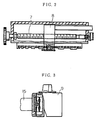
- Fig. 1 shows a conventional liquid infusion apparatus having a driving means comprising a CPU 1, a motor driving circuit 2, a potentiometer output processing circuit 3, an encoder output processing circuit 4, a motor 5, gears 6, a feed screw 7, a carriage 8, a slider 9 (plunger pushing out portion), a rotary encoder 10, a potentiometer 13, a hook 11 for operating the potentiometer 13, a wire 12, a cyringe 14, and a plunger 15.
- the cyringe 14 having the plunger 15 therein is mounted stationarily.
- the feed screw 7 is arranged in parallel with said cyringe 14, connected to the motor 5 through the gears 6, and brought into engagement with the carriage 8.
- the slider 9 is connected to the carriage 8 and brought into engagement with an end of the plunger 15.
- the rotary encoder 10 is connected to the motor 5 or the feed screw 7.
- the potentiometer 13 is arranged at a position in parallel with the feed screw 7.
- the hook 11 is connected to an end of the wire 12 for rotating said potentiometer 13 and arranged so as to engage with the carriage 8 when the carriage 8 is moved to a remaining liquid quantity small section.
- the output of the rotary encoder 10 is applied to the CPU 1 through the encoder output processing circuit 4 and processed.
- the output of the potentiometer 13 is applied to the CPU 1 through the potentiometer output processing circuit 3 and processed.
- the motor is driven by a signal from the CPU 1 through the motor driving circuit 2, so that the plunger 15 is pushed out at a predetermined speed through a predetermined length to exhaust the liquid in the cyringe.
- a further or second conventional liquid infusion apparatus shown in the Japanese Patent Application Laid-Open No. 42218/93 comprises a driving means for driving a plunger of a cyringe to move at a predetermined speed between a first and a second positions, and a first linear encoder arranged between a third and fourth positions corresponding to the first and second positions, respectively, for detecting the absolute position and the moving distance of said plunger.
- Fig. 2 shows the essential portion thereof.
- an object of the present invention is to provide a liquid infusion apparatus having a driving means which can detect exactly and control the movement of the plunger so as to solve the above problems.
- Japanese Patent Application Laid-Open No. 44390/88 discloses an improved liquid infusion apparatus comprising a feed screw to be driven by a prime mover, and a slider movable linearly, wherein the slider is brought into engagement with said feed screw so as to push out a plunger in a cyringe and to exhaust liquid in the cyringe, and a pressure exerted on the plunger by the slider is detected and compared with a reference value to generate a warning signal.
- a pressure sensor is provided at a plunger pushing portion of the slider and an output of the sensor is compared with a plurality of reference values so as to generate the warning signal and to carry out safely the infusion.
- a pressure sensor is provided at a plunger pushing portion of the slider and an output of the sensor is compared with a plurality of reference values so as to generate the warning signal and to carry out safely the infusion.
- an end of the plunger is brought into contact simply with the slider, and accordingly in case that the plunger is sucked into the cyringe by an attractive force due to the negative pressure applied to the cyringe, the slider is brought into disengagement with the plunger, so that the liquid infusion cannot be attained, but such state cannot be detected.
- the other object of the present invention is to provide a liquid infusion apparatus which can detect the negative pressure applied to the plunger.
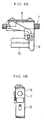
- Figs. 4A and 4B are views explaining the operation of the other conventional liquid infusion apparatus.
- Fig 4A shows such a state that the cyringe 14 and the plunger 15 are not yet mounted on the main body of the apparatus.
- Fig. 4B shows such a state that the cyringe 14 and the plunger 15 are mounted on the main body.
- a reference numeral 14-1 denotes a flange of the cyringe 14
- a reference numeral 15-1 denotes a flange of the plunger 15.
- a reference numeral 16 denotes a slider
- 16-1 denotes a holding member provided at the slider 16 for holding the flange 15-1 of the plunger
- 16-2 denotes a pushing portion of the slider
- 16-3 denotes a grooved portion formed on the holding member 16-1
- 17 denotes a lever of a slider unlock means (not shown).
- a reference numeral 17-1 denotes a push button of the lever 17, 17-2 denotes a pivot shaft of the lever 17, 21 denotes a main body of the liquid infusion apparatus, and 21-1 denotes a groove provided at the main body 21 for receiving therein the flange 14-1 of the cyringe 14.
- the slider 16 is disengaged from the feed screw 7 by pushing the pushing button 17-1 of the lever 17, the slider 16 is moved toward the flange 15-1 of the plunger 15, and the pushing portion 16-2 is brought into contact with an outer end of the plunger 15, so that the cyringe 14 and the plunger 15 are fixed to the main body 21 as shown in Fig. 4B.
- the width of the grooved portion 16-3 is determined corresponding to the maximum thickness of the flange 15-1 of the plunger 15.
- the width of the grooved portion 16-3 of the holding member 16-1 is fixed, and accordingly, if the thickness of the flange 15-1 of the plunger 15 is smaller than that of the grooved portion, the plunger 15 cannot be held positively by the slider 16.
- the rotary direction of the motor is limited to only one direction by a motor driving program and an electric circuit thereof.
- Japanese Utility Model Application Laid-Open No. 89053/83 discloses an improved liquid infusion apparatus comprising a feed screw driven by a prime mover, and a slider movable linearly, engaged with the feed screw so as to push out the plunger of the cyringe and infuse liquid from the cyringe, wherein the engagement and disengagement of the slider with the feed screw can be carried out corresponding to that of the slider with the cyringe.
- said conventional infusion apparatus as shown in Figs.
- a sliding means is provided at a driving pawl which is fitted into a driving member when the cyringe is installed on the main body, so that a feed screw is disengaged from a half-nut fixed to said driving member at the same time of the sliding of the driving pawl.
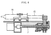
- Japanese Patent Application Laid-Open No. 247347/91 discloses a further conventional liquid infusion apparatus as shown in Fig. 6.
- a movable block is provided movably reciprocally in an axial direction of a cyringe and connected to a driving means, and a pushing portion of a plunger is provided at the movable block movably reciprocally between a position where the pushing portion is engaged with the plunger and a position where the pushing portion is disengaged from the plunger, and a half-nut is engaged with and disengaged from a feed screw according to the movement of the movable block.
- the apparatus shown in Figs. 5A and 5B, or shown in Fig. 6 has such problems that in the loading state the half-nut is floated on the feed screw, because the half-nut is normally urged to the feed screw by a spring, so that the precise feeding operation cannot be carried out. Further, in the conventional apparatus, operations for engaging the plunger with the slider and for disengaging the plunger from the slider are carried out at the same time with operations for engaging the feed screw with the half-nut and for disengaging the feed screw from the half-nut.
- the feed screw so as to have teeth of rectangular in cross section, which is in parallel with a vertical plane normal to the feeding direction of the feed screw, in order to prevent the half-nut from floating from the feed screw in case of loading.
- the feed screw having teeth of the rectangular cross section is high in manufacturing cost, because the manufacturing steps thereof are limited.
- the other problem is that the flange of the plunger cannot be held precisely by the holding member, because a gap is formed between the flange of the plunger and the groove of the holding member due to the manufacturing precision.
- the task of the present invention is to solve the above problems and to provide a liquid infusion apparatus of high precision and inexpensive.
- a liquid infusion apparatus has means for fixing an outer cylinder of a cyringe and driving means for pushing a plunger in a predetermined direction so as to exhaust liquid in the cyringe, and is characterized by comprising an incremental linear encoder arranged along the feeding axis of said driving means for pushing the plunger, detecting means of said incremental linear encoder mounted on a slider portion of said driving means for pushing the plunger, means for processing an output of said detecting means, applying to an UP/DOWN counter and comparing with an initial value inputted previously so as to generate a signal indicating a moving quantity of said plunger, and a sensor provided in the vicinity of an end of said outer cylinder for setting along said feeding axis a remaining liquid quantity small section, wherein said counter is reset or the counted value is memorized and then the counting is started by an output of said sensor so as to determine a position of the plunger at said remaining liquid quantity small section.
- the moving quantity and the position of the carriage for moving the plunger can be detected directly by an inexpensive incremental linear encoder. Further, the absolute position at the remaining infusion liquid quantity small section can be recognized in non-contact manner by counting feedback pulses from the encoder after that the carriage is passed across the detecting sensor for detecting the starting point of the remaining infusion liquid quantity small section.
- a holding arm for holding a flange of a plunger is provided rotatably and movably in a movable direction of a slider so as to push the flange of the plunger to the slider by the holding arm for holding.
- the flange of the plunger can be held precisely by the slider, even if the size of the cyringe is varied, because the flange of the plunger is pushed to the slider by the holding arm for holding.
- a liquid infusion apparatus of the present invention has a holding arm for pushing the flange of said plunger in a direction reverse to a pushing direction of the plunger toward a plunger holding portion of said slider for holding, a pressure sensor provided at said plunger holding portion of the slider, and a processing circuit for comparing an output of said pressure sensor with a plurality of reference values to generate a processing signal.
- the plunger can be held by the slider, and a negative pressure state can be detected by comparing an output of said pressure sensor in case that the flange of said plunger is held by the plunger holding portion by the holding arm with the reference values.
- a liquid infusion apparatus has a feed screw driven by a prime mover and a slider movable linearly and engaged with said feed screw so as to push a plunger of a cyringe for exhausting liquid in the cyringe, and is characterized by comprising a lever supported rotatably freely by a first shaft arranged horizontally and normally to a moving direction of said slider, a push button provided at one end of said lever so as to project from said slider, a slider releasing device, an interlocking rod interlocking with said slider releasing device, the other end of said lever being contacted with said interlocking rod, holding means supported by said slider rotatably by a second shaft, which is in parallel to said first shaft for press holding the flange of the plunger by the slider, a spring for urging the holding means to rotate in the clockwise direction, and interlocking means for interlocking said holding means with said lever.
- the flange of the plunger can be held positively by the slider, even if the size of the thickness of the flange of the plunger is varied, because the flange of the plunger is pushed to the slider by the holding arm for holding.
- a liquid infusion apparatus of the present invention is characterized by comprising a half-nut releasing device interlocking with a releasing lever mounted on the slider, said half-nut releasing device comprising means for engaging the feed screw with the half-nut and disengaging the feed screw from the half-nut moved by a releasing cam having a step portion, and means for pushing the flange of the plunger to the slider by the holding arm for holding.
- the cross section of the tooth of the feed screw is inclined to a plane normal to the feeding direction of the screw, so that the feed screw can be manufactured by the form rolling process etc. in mass production basis.
- the releasing cam of the half-nut releasing device is moved in the forward direction of the interlocking rod to urge the half-nut to the feed screw, so that the releasing cam receives a component force in the vertical direction of a force applied to the half-nut on loading, thereby causing the half-nut is prevented from floating.
- the flange of the plunger is pushed to the slider by the arm provided at the slider, the flange is held positively by the slider and no gap is formed between the contact portion of the slider and the end of the plunger, so that the movements of the slider and the plunger coincide perfectly with each other and precise liquid infusion can be realized.
- a liquid infusion apparatus has a feed screw driven by a prime mover and a slider movable linearly and engaged with said feed screw so as to push a plunger of a cyringe for exhausting liquid in the cyringe, and is characterized in that means for transmitting a driving force only in a cyringe pushing direction is inserted between the feed screw and the prime mover.
- a mechanical backstop is provided between a rotary shaft of the electric motor and the feed screw, so that even if the electric motor is rotated reversely by the external noise the feed screw is prevented from rotating reversely, and the danger of the malfunction can be avoided.
- Fig. 7 is a schematic view of a liquid infusion apparatus according to the present invention. Parts of the apparatus which are similar to corresponding parts of the conventional apparatus shown in Fig. 1 have been given corresponding reference numerals and need not be further redescribed.
- a plate 22 of a linear encoder is provided in parallel with a feeding screw 7, and a photo-coupler 23 of a carriage 8 is provided so as to face to said plate 22.
- a sensor 24 is provided in the vicinity of an end of said plate 22 corresponding to an end of a cyringe 14.
- a dog 26 is provided on said carriage 8 so as to actuate said sensor 24.
- An output of said photo-coupler 23 is applied to a CPU 1 through an encoder output processing circuit 4, and an output of said sensor 24 is applied to the CPU 1 through a sensor output processing circuit 25.
- an incremental linear encoder is composed of the plate 22 arranged in parallel with the feeding screw 7, and the photo-coupler 23 fixed to the carriage 8, which is stationarily engaged with a slider 9. Further, the dog 26 for a remaining liquid quantity small section is mounted on the carriage 8, and the sensor 24 for the remaining liquid quantity small section is actuated by the movement of the carriage 8.
- a pulse signal generated between the plate 22 with slits and the photo-cupler 23 mounted on the carriage 8 is processed in the encoder output processing circuit 4 and applied to the CPU 1 as an information to show the movement of the carriage 8, so that the movement of the carriage 8 can be monitored directly.
- a signal generated when the dog 26 mounted on the carriage 8 is moved across the sensor 24 is processed by the sensor output processing circuit 25 and applied to the CPU 1 as an information of position. Then an encoder feedback pulse obtained by processing the pulse signal generated from the photo-coupler 23 by the encoder output processing circuit 4 is applied to an UP/DOWN counter and compared with an initial value applied to the UP/DOWN counter previously to recognize in non-contact manner an absolute position of the plunger at the remaining liquid quantity small section.
- an example of an optical incremental linear encoder for use in the liquid infusion apparatus comprises an opaque planar plate 22 having fine slits 22-1 equidistantly apart from one another, and a photo-coupler 22-2 consisting of a light emitting element 22-3 and a light receiving element 22-4, wherein a pulse signal is obtained when the slit 22-1 of the plate 22 is moved across the optical axis of said photo-coupler 22-2.
- a photo-coupler 22-2 consisting of a light emitting element 22-3 and a light receiving element 22-4, wherein a pulse signal is obtained when the slit 22-1 of the plate 22 is moved across the optical axis of said photo-coupler 22-2.
- an optical incremental linear encoder of the other embodiment of the present invention comprises the plate 22 with the slits, a light reflecting plate 22-5 arranged in the vicinity of and in parallel with said plate 22, and a photo-coupler 22-6 consisting of a light emitting element 22-7 and a light receiving element 22-8 arranged at the opposite side of the light reflecting plate 22-5 with respect to the plate 22, wherein a pulse signal can be obtained corresponding to a reflected light reflected from the light reflecting plate 22-5 through the slit 22-1 of the plate 22.
- Both optical incremental linear encoders are the same in function with each other and can be used similarly.
- the incremental linear encoder having the opaque planar plate having the fine slits equidistantly apart from one another for use in the liquid infusion apparatus of the present invention is simple in construction and low in manufacturing cost compared with the conventional absolute value type linear encoder shown in Fig. 2, wherein a plurality of transparent sections of which width is narrower in consecutive order are formed on both of the transparent and non-transparent portions.
- the incremental encoder of the present invention has such features that the plate with slits can be manufactured low in cost and that a high precision detecting signals of the moving speed, the moving distance and the absolute position etc. of the plunger can be obtained economically by processing and converting the output by a processing circuit.
- a magnetic type incremental linear encoder where in a magnetic scale plate having N poles and S poles formed alternately with a constant pitch is arranged at a position of the slit plate, and a magnetic detection device is arranged at a position of the photo sensor, can be used.
- the detection's of the moving distance of the plunger and the absolute position of the plunger at the liquid remaining area can be realized in non-contact manner by detecting the actual motion of the carriage for pushing out the plunger.
- FIG. 9A is a side view of the essential portion of the apparatus according to the present invention
- Fig. 9B is a front view, taken along the lines A-A ' of Fig. 9A and viewed in the direction of arrow.
- Figs. 10A and 10B show a state that the flange of the plunger in the cyringe is held by the slider portion.
- Fig. 10A is a side view of the essential portion of the apparatus according to the present invention
- Fig. 10B is a front view, taken along the lines A-A ' of Fig. 10A and viewed in the direction of arrow.
- a push button 17-1 is pushed, the holding arms 27 of a slider 16 for holding the flange of the plunger are rotated around shafts 27-1, and opened so that the slider 16 can be approached to the end of said plunger without contacting with the holding arms 27. Then, as shown in Fig. 10A, the slider 16 is moved in the leftward direction in Fig. 9A so that a contact surface 16-1 of the slider 16 is brought into contact with the end surface of the plunger 15. When the push button 17-1 of the slider 16 is retracted, the holding arms 27 are rotated so as to engage with the flange 15-1 of the plunger as shown in Fig. 10B, and the slider 16 is approached to the flange of the plunger for holding.
- Figs. 11A to 11C are views for explaining the essential portions of the slider 16 shown in Figs. 9A and 9B, and Figs. 10A and 10B.
- Fig. 11A shows a state that the holding arms 27 for holding the flange of the plunger are closed.
- Fig. 11B shows a state that the holding arms 27 are opened.
- Fig. 11C shows a state that the cyringe 14 and the plunger 15 are held by the slider 16.
- Figs. 11A shows a state that the holding arms 27 for holding the flange of the plunger are closed.
- Fig. 11B shows a state that the holding arms 27 are opened.
- Fig. 11C shows a state that the cyringe 14 and the plunger 15 are held by the slider 16.
- Figs. 11A shows a state that the holding arms 27 for holding the flange of the plunger are closed.
- Fig. 11B shows a state that the holding arms 27 are opened.
- a reference numeral 27-2 denotes a screw groove on the shaft 27-1
- a reference numeral 28 denotes a driving lever of the holding arm
- 28-1 denotes a shaft for the lever
- 28-2 denotes an engaging pin engaging with the screw groove 27-2
- 29 denotes a return spring.
- Two holding arms 27 and parts corresponding thereto are provided so as to be rotated in the directions opposite to each other.
- FIG. 11A when the push button 17-1 is returned the lever 17 of the releasing device is returned and the driving lever 28 of the holding arms 27 is also returned. Accordingly, the shafts 27-1 are moved in the rightward direction by the action of the engaging pins 28-2 and the screw grooved 27-2, so that the holding arms 27 are closed.
- the holding arms 27 approach to a contact portion 16-2 of the plunger, because the cyringe 14 is not yet mounted.
- Figs. 11A and 11B show a state that the push button 17-1 is operated in the absence of the cyringe. As shown in Fig.
- the holding arms 27 urge the flange 15-1 of the plunger to the contact portion 16-2 of the slider 16 for holding.
- two holding arms 27 urge the flange 15-1 to the contact portion 16-2 of the slider with the force of the return spring 29 for holding, so that the flange 15-1 of the plunger can be held positively by the slider 16, ever if the thickness of the flange 15-1 is varied.
- the cyringe 14 In case that the cyringe 14 is to be released from the main body 21 of the liquid infusion apparatus, the cyringe 14 can be released easily from the main body 21, because two holding arms 27 are opened when the push button 17-1 is pushed.
- the holding arms for holding the flange of the plunger are moved in the moving direction of the slider and rotated to hold the flange of the plunger easily, and by returning the push button the holding arms urge the flange to the slider for holding. Accordingly, the flange can always be held by the slider positively even if the size of the cyringe is changed.
- FIGs. 12A ⁇ 12C each shows an enlarged cross section of essential portions of the slider 16.
- Fig. 12A shows a state that the holding arms 27 are opened and the flange of the plunger 15 is not mounted on the slider 16.
- Fig. 12B shows a state that the holding arms 27 are closed.
- Fig. 12C shows a state that the flange 15-1 of the plunger 15 is held by the holding arms 27.
- the explanation of the driving means for the holding arms 27 is omitted.
- a reference numeral 30 denotes a pressure sensor and 31 denotes a pressure transmitting portion.
- the pressure sensor 30 is fixed to the slider 16, and a pressure receiving portion thereof is connected to the contact portion 16-2 through the pressure transmitting portion 31.
- the holding arms 27 are not contacted with the contact portion 16-2 of the slider, so that no pressure is applied to the pressure sensor 30.
- Fig. 12C the flange 15-1 of the plunger is contacted with the contact portion 16-2 of the slider, the holding arms 27 are closed, and the holding arms 27 urge the flange 15-1 of the plunger to the contact portion 16-2 of the slider with the force of return springs 29.
- an output corresponding to the force of the return spring 29 is generated from the pressure sensor 30, because the flange 15-1 of the plunger is pressed to the contact portion 16-2 by the return springs 29.
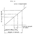
- Fig. 13 is a diagram showing the relation between the pressure applied to the pressure sensor 30 and the output thereof, and a point 1 of the ordinate corresponds to zero pressure and points 2, 3, 4 each corresponds to each pressure of the operation states.
- the point 1 of the ordinate shows a state that the cyringe is not mounted on the slider as shown in Figs. 12A and 12B, so that no pressure is applied to the pressure sensor 30 and the output is zero.
- the point 3 of the ordinate shows a state that the flange 15-1 of the plunger is contacted with the contact portion 16-2 of the slider and pressed by the holding arms 27 for holding as shown in Fig. 12C, so that the output of the pressure sensor corresponds to the force of the return spring 29. In this state, the motor 5 is inoperative and the slider 16 does not urge the plunger 15.
- the slider 16 engaged with the feed screw 7 urges the plunger 15 in the predetermined direction at a predetermined speed to exhaust the liquid.
- the output of the pressure sensor 30 is increased to a value more than the point 3 corresponding to the value of pressure required normally to exhaust liquid, so that the maximum pressure is determined as a point 4.
- the point 2, for example, is determined between the points 3 and 1 in order to detect the negative pressure applied to the plunger.
- the points 1, 2, 3 and 4 shown in Fig. 13 are set in a comparison circuit (not shown) and compared with the output of the pressure sensor 30 to generate processing signals corresponding to each state.
- a signal indicating that no cyringe is set is generated.
- a signal indicating that the operation is normal is generated.
- a signal indicating the overload state is generated.
- a signal indicating that the negative pressure is applied to the plunger is generated.
- liquid infusion apparatus of the present invention having the above construction, by comparing the output of the pressure sensor with the values set in the comparison circuit, signals indicating the overload state, out of cyringe state, and negative pressure generating state, respectively, can be generated, so that the liquid infusion operation can be carried out safely.
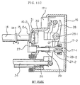
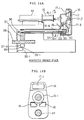
- FIG. 14A shows a side view of essential portions of a state that the flange 15-1 of the plunger is not mounted on the slider 16.
- Fig. 14B shows a front view, taken along the lines A-A' of Fig. 14A and viewed in the direction of arrow.
- Fig. 15A shows a side view of essential portions of a state that the flange 15-1 of the plunger is held by the slider.
- Fig. 15B is a front view, taken along the lines A-A' of Fig. 15A and viewed in the direction of arrow.
- FIGs. 14A, 14B, 15A, and 15B two holding arms 18 of the slider 16 for holding the flange of the plunger are supported by the shafts 18-1 rotatably freely and urged to rotate by springs 33 in the clockwise direction, each of said holding arms having a small projection 32 at the side face thereof.
- the lever 17 for operating an interlocking rod 34 interlocking with the releasing device (not shown) of the slider is supported by a shaft 17-2 rotatably freely, and a projection 17-3 is provided so as to project in the leftward direction from a position lower than said shaft 17-2 of the lever 17, so that when said push button 17-1 of the lever 18 is pushed, said arm 18 is rotated in the counter-clockwise direction against the force of the spring 33 by the tip end of the projection 17-3 through the small projection 32 provided at the side face of the arm 27. Accordingly, the holding arms 18 are opened to receive therein the flange 15-1 of the plunger easily.
- the projection 17-3 of the lever 17 is retracted, the holding arms 18 is rotated in the clockwise direction by the force of the spring 33, and the flange 15-1 of the plunger is brought into contact with the contact portion 16-2 of the slider 16 for holding, when the slider 16 is moved to a direction directing to the end portion of the plunger 15 of the cyringe so that the contact portion 16-2 of the slider 16 is brought into contact with the end of the plunger, and the push button 17-1 of the lever 17 is returned.
- the flange 15-1 of the plunger can be held positively even if the size of the flange is varied according to the mechanical precision, because the flange 15-1 of the plunger is pressed to the contact portion 16-2 of the slider 16 by the holding arms 18 with the force of the springs 33 for holding.
- the cyringe 14 In case that the cyringe 14 is to be released from the main body 21 of the liquid infusion apparatus, the cyringe 14 can be released easily, because the holding arms 18 are opened to release the flange of the plunger when the push button 17-1 of the lever 17 is pushed.
- the press holding and release of the flange can be carried out by the operation to push the slider release button when the cyringe is mounted on or released from the main body of the liquid infusion apparatus, so that the handling is very easy and the load of the operator becomes small.
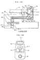
- FIG. 16A is a side view of essential portions of the apparatus according to the present invention.
- Fig. 16B is a cross section of the essential portion, taken along the lines A-A' of Fig. 16A.
- Figs. 17A and 17B show a state that the half-nut is released.
- Fig. 17A is a side view of the essential portion of the apparatus.
- Fig. 17B is a cross section of the essential portion, taken along the lines A-A' of Fig. 17A.
- reference numeral 16-4 denotes an extending portion of the slider 16
- reference numeral 35 denotes a return spring for an interlocking rod 34
- 36 denotes a half-nut releasing device
- 36-1 denotes a releasing cam
- 37 denotes a half-nut holding portion
- 37-1 denotes a half-nut sliding groove
- 37-2 denotes a release spring for the half-nut
- 38 denotes a feed screw
- 39 denotes a half-nut
- 39-1 denotes a bearing.
- the half-nut holding portion 37 is provided on the extending portion 16-4 of the slider 16 extending along the feed screw 38 movably freely with respect to the feed screw 38, and the half-nut sliding groove 37-1 extending normally to the feed direction of the feed screw 38 is provided at the half-nut holding portion 37.
- the half-nut 39 is inserted slidably into the sliding groove 37-1 to support the half-nut by the feed screw detachably, and the half-nut releasing device 36 is fixed on the tip end of the interlocking rod 34 having the return spring 35 arranged in parallel with the extending portion 16-4.
- the releasing cam 36-1 having a step extending to the forward direction of the interlocking rod 34 is formed on the half-nut releasing device 36 at a position facing the end portion of the half-nut 39, the bearing 39-1 provided at the end of the half-nut 39 is brought into contact with the releasing cam 36-1, and the half-nut 39 is urged to a releasing direction by a spring 36-2 for releasing.
- the releasing can of the half-nut releasing device 36 fixed to the interlocking rod 34 is moved leftwards, and the bearing 39-1 of the half-nut 39 is brought into contact with the lower step of the releasing cam 36-1, so that the half-nut 39 is separated from the feed screw 38 by the force of the spring 36-2, when the push button 17-1 of the releasing lever 17 is pushed, and the interlocking rod 34 is moved leftwards against the force of the return spring 35.
- the interlocking rod 34 is moved rightwards, and the bearing 39-1 of the half-nut 39 is brought into contact with the upper step of the releasing cam 36-1, so that the half-nut 39 is brought into engagement with the feed screw 38 against the force of the spring 36-2, when the push button 17-1 of the releasing lever 17 is retracted, and the interlocking rod 34 is moved rightwards by the force of the return spring 35.
- the half-nut 39 is prevented from floating from the feed screw, because the half-nut 39 is urged in the direction normal to the feeding direction of the feed screw by the upper step of the releasing cam.
- FIGs. 18A and 18B show a state that the flange of the plunger is not yet held by the slider 16.
- Fig. 18A is a sectional side view of the essential portion.
- Fig. 18B is a view, taken along the lines A-A' of Fig. 18A.
- Figs. 19A and 19B show a state that the flange of the plunger is held by the slider 16.
- Fig. 19A is a sectional side view of the essential portion.
- Fig. 19B is a view, taken along the lines A-A ' of Fig. 19A.
- the slider 16 is arranged at a position remote from the plunger 16, and when the push button 17-1 is pushed the slider releasing lever 17 is rotated around the shaft 17-2 and the projection 32 of the arm 18 is pushed by the tip end of the projection 17-3 at the left side of the slider releasing lever 17, so that the arm 18 is rotated in the counter-clockwise direction against the force of the return spring 33.
- the tip end of the arm 18 is lowered from the position of the flange 15-1 of the plunger so that the flange 15-1 of the plunger can be passed easily through the arms.
- the holding arms 18 are positioned at the outside of the flange 15-1 of the plunger.
- the bearing 39-1 is brought into contact with the lower step of the releasing cam 36-1, and the half-nut 39 is lowered by the force of the spring 36-2 and separated from the feed screw 38, so that the slider can be moved freely in the moving direction of the plunger, when the interlocking rod 34 is moved in the leftward direction against the force of the return spring 35 by the other end of the slider releasing lever 17 to move the half-nut releasing device 36 connected to the interlocking rod 34 in the leftward direction.
- the projection 17-3 of the releasing lever 17 is retracted, and the holding arm 18 is rotated in the clockwise direction, so that the flange 15-1 of the plunger is pressed to the contact portion 16-2 of the slider 16 and held by the tip end of the holding arm 18, when the slider 16 is moved toward the end portion of the plunger to bring the contact portion 16-2 of the slider 16 into contact with the end portion of the flange 15-1 of the plunger 15, and the push button 17-1 of the releasing device of the slider is released.
- the half-nut releasing device 36 connected to the interlocking rod 34 is also moved in the rightward direction, so that the bearing 39-1 of the half-nut is brought into contact with the upper step of the releasing cam 36-1, and the half-nut 39 is moved upwardly against the spring 36-2 and brought into engagement with the feed screw 38.
- the upper step of the releasing cam 36-1 is formed in parallel with the feed screw, the precise feeding can be attained, because the floating movement in the radial direction of the half-nut is prevented even if a load is applied to the feed screw 38.
- Figs. 20A and 20B show a state that the flange of the plunger of the cyringe is not yet held by the slider 16.
- Fig. 20A is a side view of essential portions.
- Fig. 21B is a view, taken along the lines A-A ' of Fig. 21A.
- the slider 16 is positioned remote from the flange 15-1 of the plunger of the cyringe 14, and two holding arms 27 supported by the shafts 27-1 are separated from the slider 16 by the internal mechanism of the slider 16, rotated in the directions of arrows and opened so that the flange 15-1 of the plunger can be brought into contact with the contact portion 16-2.
- two holding arms 27 supported by the shafts 27-1 approach the slider 16 and are rotated in the directions of arrows and closed, so that the flange 15-1 of the plunger is pressed to and held by the contact portion 16-2 of the slider 16, when the slider 16 is moved toward the plunger to bring the contact portion 16-2 into contact with the flange 15-1 of the plunger, and the release button 17-1 is retracted.
- Fig. 20A is a cross section of the essential portion in a state that the plunger is not yet contacted with the slider 16.
- Fig. 20B is a side view, taken along the lines A-A' of Fig. 20A.
- Fig. 20B shows a state that the release button 17-1 is pushed, and the interlocking rod 34 is moved in the leftward direction, so that the bearing 39-1 of the half-nut is brought into contact with the lower step of the releasing cam 36, and the half-nut 39 is lowered by the force of the spring 36-2 to release the engagement of the feed screw 38.
- Two holding arms 27 are supported rotatably freely by the shafts 27-1 and movably in the forward direction of the slider 16.
- a guide groove for rotation is formed at one side of the shaft 27-1 opposite to the other side of the shaft 27-1 on which the holding arm 27 is mounted.
- the holding arm 27 is urged to the plunger contact surface of the slider by the return spring 29.
- the driving lever 28 for driving the holding arm 27 supported by the shaft 17-2 is rotated in the clockwise direction when the releasing button 17-1 is pushed.
- the shaft 27-1 is moved in the leftward direction against the return spring 29 and rotated by the action of the guide groove 27-2 because the engaging pin 28-2 provided at one end of the lever 28 is engaged with the guide groove 27-2 provided on the shaft 27-1 of the holding arm 27, so that as shown in Fig. 20B the holding arms 27 are opened and the flange of the plunger can be brought into contact with the contact surface of the slider 16.
- the driving lever 28 for the holding arm 27 is rotated in the counter-clockwise direction, the engaging pin 28-2 engaged with the guide groove 27-2 of the shaft 27-1 is moved in the rightward direction, and the holding arm 27 is rotated by the force of the spring 29, so that the flange is pressed to and held by the contact portion 16-2 of the slider 16.
- the flange of the plunger can be held positively by the slider, because the holding arm 27 is attracted toward the plunger contact surface of the slider by the force of the return spring 29 while the shaft 27-1 is rotated.
- the cross section of the tooth of the feed screw 34 is inclined to a plane normal to the feeding direction of the screw, so that the feed screw can be manufactured by the form rolling process etc. economically with high precision.
- the half-nut 39 may be floated in the radial direction thereof on loading.
- the upper step of the release cam 36-1 is formed in parallel with the screw 38 and urges the half-nut 39 toward the screw 38, so that the half-nut 39 is prevented from floating to ensure the precise feeding.
- the cross section of the tooth of the feed screw 38 is saw tooth shape and the vertical surface thereof is determined as the forward side, the floating of the half-nut 39 on loading can be prevented, and the screw can be manufactured economically and easily.
- the engagement and disengagement of the slider with the feed screw can easily be carried out by the operation of the slider release button, and the flange of the plunger can be pressed to and held by the rotatable slider.
- the feed screw 7 is connected to the rotary shaft of the electric motor 5 through a pinion 6-1, a one-way clutch 19 and a large gear 6-2.
- a conventional clutch as shown in Fig. 23 can be used.
- the clutch comprises a cylinder 7-2 fixed coaxially to an axis 7-1 of the feed screw 7, a plurality of triangular grooves 7-3 formed on the outer periphery of the cylinder 7-2, an outer cylinder 20 fixed to said large gear 6-2, the inner peripheral surface of said outer cylinder 20 facing the outer peripheral surface of said cylinder 7-2, and balls 20-1 each inserted into a space formed between the inner peripheral surface of said outer cylinder 20 and said triangular groove 7-3.
- the above liquid infusion apparatus has such an excellent function that the wrong operation, such as the reverse moving of the plunger can be prevented even if the electric motor is rotated reversely due to the electric noises or the like.
- liquid infusion apparatus of the present invention is useful for the oscillating device of the plunger of the cyringe.
Abstract
Description
- The present invention relates to a liquid infusion apparatus, and more particularly, relates to a liquid infusion apparatus having a driving means for infusing liquid by pushing a plunger into a cyringe.
- Fig. 1 shows a conventional liquid infusion apparatus having a driving means comprising a
CPU 1, amotor driving circuit 2, a potentiometeroutput processing circuit 3, an encoderoutput processing circuit 4, amotor 5, gears 6, afeed screw 7, acarriage 8, a slider 9 (plunger pushing out portion), arotary encoder 10, apotentiometer 13, a hook 11 for operating thepotentiometer 13, awire 12, acyringe 14, and aplunger 15. In said conventional infusion apparatus shown in Fig. 1, thecyringe 14 having theplunger 15 therein is mounted stationarily. Thefeed screw 7 is arranged in parallel with saidcyringe 14, connected to themotor 5 through the gears 6, and brought into engagement with thecarriage 8. Theslider 9 is connected to thecarriage 8 and brought into engagement with an end of theplunger 15. Therotary encoder 10 is connected to themotor 5 or thefeed screw 7.
Thepotentiometer 13 is arranged at a position in parallel with thefeed screw 7. The hook 11 is connected to an end of thewire 12 for rotating saidpotentiometer 13 and arranged so as to engage with thecarriage 8 when thecarriage 8 is moved to a remaining liquid quantity small section. The output of therotary encoder 10 is applied to theCPU 1 through the encoderoutput processing circuit 4 and processed. The output of thepotentiometer 13 is applied to theCPU 1 through the potentiometeroutput processing circuit 3 and processed. The motor is driven by a signal from theCPU 1 through themotor driving circuit 2, so that theplunger 15 is pushed out at a predetermined speed through a predetermined length to exhaust the liquid in the cyringe. - A further or second conventional liquid infusion apparatus shown in the Japanese Patent Application Laid-Open No. 42218/93 comprises a driving means for driving a plunger of a cyringe to move at a predetermined speed between a first and a second positions, and a first linear encoder arranged between a third and fourth positions corresponding to the first and second positions, respectively, for detecting the absolute position and the moving distance of said plunger. Fig. 2 shows the essential portion thereof.
- In the first conventional apparatus, no actual feeding quantity of the carriage can be detected in case that a slip is generated about the feed screw or the motor, or the carriage is floated on the feed screw, and no actual position of the remaining liquid quantity small section can be detected in case that the wire is cut, or the contact of the electric terminal of the potentiometer is failure. Further, in the second conventional apparatus, such problems that the actual feeding quantity of the carriage can not be detected because of the slip about the feed screw or the motor, or of the floatation of the carriage on the feed screw can be solved, because in the second conventional apparatus, the moving state of the carriage is detected by the linear encoder. However, the second conventional apparatus has such a problem that the linear encoder for detecting the absolute value is expensive and the skill is required. Accordingly, an object of the present invention is to provide a liquid infusion apparatus having a driving means which can detect exactly and control the movement of the plunger so as to solve the above problems.
- Further, Japanese Patent Application Laid-Open No. 44390/88 discloses an improved liquid infusion apparatus comprising a feed screw to be driven by a prime mover, and a slider movable linearly, wherein the slider is brought into engagement with said feed screw so as to push out a plunger in a cyringe and to exhaust liquid in the cyringe, and a pressure exerted on the plunger by the slider is detected and compared with a reference value to generate a warning signal.
- In said liquid infusion apparatus, a pressure sensor is provided at a plunger pushing portion of the slider and an output of the sensor is compared with a plurality of reference values so as to generate the warning signal and to carry out safely the infusion. As shown in Fig. 3, however, in said liquid infusion apparatus an end of the plunger is brought into contact simply with the slider, and accordingly in case that the plunger is sucked into the cyringe by an attractive force due to the negative pressure applied to the cyringe, the slider is brought into disengagement with the plunger, so that the liquid infusion cannot be attained, but such state cannot be detected. Accordingly, the other object of the present invention is to provide a liquid infusion apparatus which can detect the negative pressure applied to the plunger.
- Figs. 4A and 4B are views explaining the operation of the other conventional liquid infusion apparatus. Fig 4A shows such a state that the
cyringe 14 and theplunger 15 are not yet mounted on the main body of the apparatus. Fig. 4B shows such a state that thecyringe 14 and theplunger 15 are mounted on the main body. In Figs. 4A and 4B, a reference numeral 14-1 denotes a flange of thecyringe 14, a reference numeral 15-1 denotes a flange of theplunger 15. Areference numeral 16 denotes a slider, 16-1 denotes a holding member provided at theslider 16 for holding the flange 15-1 of theplunger 15, 16-2 denotes a pushing portion of theslider 16, 16-3 denotes a grooved portion formed on the holding member 16-1, and 17 denotes a lever of a slider unlock means (not shown). A reference numeral 17-1 denotes a push button of thelever 17, 17-2 denotes a pivot shaft of thelever main body 21 for receiving therein the flange 14-1 of thecyringe 14. In order to install thecyringe 14 and theplunger 15 to themain body 21 of the liquid infusion apparatus shown in Fig. 4A, theslider 16 is disengaged from thefeed screw 7 by pushing the pushing button 17-1 of thelever 17, theslider 16 is moved toward the flange 15-1 of theplunger 15, and the pushing portion 16-2 is brought into contact with an outer end of theplunger 15, so that thecyringe 14 and theplunger 15 are fixed to themain body 21 as shown in Fig. 4B. The width of the grooved portion 16-3 is determined corresponding to the maximum thickness of the flange 15-1 of theplunger 15. - In the above conventional apparatus, however, the width of the grooved portion 16-3 of the holding member 16-1 is fixed, and accordingly, if the thickness of the flange 15-1 of the
plunger 15 is smaller than that of the grooved portion, theplunger 15 cannot be held positively by theslider 16. - Further, in a liquid infusion apparatus wherein the liquid infusion is carried out automatically by moving the plunger of the cyringe using a motor, it is necessary absolutely to prevent the plunger from moving in a (suction) direction contrary to the pushing direction of the plunger. Accordingly, in the conventional liquid infusion apparatus, the rotary direction of the motor is limited to only one direction by a motor driving program and an electric circuit thereof.
- Recently, however, most of electric appliances generate many kinds of electric noises (electromagnetic waves) according to the development of the electronic systems, so that many problems of wrong operation due to the noises have been encountered in the field of the medical services.
- Further, Japanese Utility Model Application Laid-Open No. 89053/83 discloses an improved liquid infusion apparatus comprising a feed screw driven by a prime mover, and a slider movable linearly, engaged with the feed screw so as to push out the plunger of the cyringe and infuse liquid from the cyringe, wherein the engagement and disengagement of the slider with the feed screw can be carried out corresponding to that of the slider with the cyringe. In said conventional infusion apparatus, as shown in Figs. 5A and 5B, a sliding means is provided at a driving pawl which is fitted into a driving member when the cyringe is installed on the main body, so that a feed screw is disengaged from a half-nut fixed to said driving member at the same time of the sliding of the driving pawl. Japanese Patent Application Laid-Open No. 247347/91 discloses a further conventional liquid infusion apparatus as shown in Fig. 6. In this apparatus, a movable block is provided movably reciprocally in an axial direction of a cyringe and connected to a driving means, and a pushing portion of a plunger is provided at the movable block movably reciprocally between a position where the pushing portion is engaged with the plunger and a position where the pushing portion is disengaged from the plunger, and a half-nut is engaged with and disengaged from a feed screw according to the movement of the movable block.
- The apparatus shown in Figs. 5A and 5B, or shown in Fig. 6 has such problems that in the loading state the half-nut is floated on the feed screw, because the half-nut is normally urged to the feed screw by a spring, so that the precise feeding operation cannot be carried out. Further, in the conventional apparatus, operations for engaging the plunger with the slider and for disengaging the plunger from the slider are carried out at the same time with operations for engaging the feed screw with the half-nut and for disengaging the feed screw from the half-nut. However, only a simple groove is provided at a holding portion of the slider for holding a flange of the plunger, so that the flange of the plunger is held unsteadily by the holding member due to the difference between the thickness of the flange of the plunger and the width of groove formed on the holding portion of the slider, which are generated by the mechanical precision. In the conventional apparatus mentioned above, it is preferable generally to shape the feed screw so as to have teeth of rectangular in cross section, which is in parallel with a vertical plane normal to the feeding direction of the feed screw, in order to prevent the half-nut from floating from the feed screw in case of loading. However, there are two problems. One problem is that the feed screw having teeth of the rectangular cross section is high in manufacturing cost, because the manufacturing steps thereof are limited. The other problem is that the flange of the plunger cannot be held precisely by the holding member, because a gap is formed between the flange of the plunger and the groove of the holding member due to the manufacturing precision.
- The task of the present invention is to solve the above problems and to provide a liquid infusion apparatus of high precision and inexpensive.
- A liquid infusion apparatus according to the present invention has means for fixing an outer cylinder of a cyringe and driving means for pushing a plunger in a predetermined direction so as to exhaust liquid in the cyringe, and is characterized by comprising an incremental linear encoder arranged along the feeding axis of said driving means for pushing the plunger, detecting means of said incremental linear encoder mounted on a slider portion of said driving means for pushing the plunger, means for processing an output of said detecting means, applying to an UP/DOWN counter and comparing with an initial value inputted previously so as to generate a signal indicating a moving quantity of said plunger, and a sensor provided in the vicinity of an end of said outer cylinder for setting along said feeding axis a remaining liquid quantity small section, wherein said counter is reset or the counted value is memorized and then the counting is started by an output of said sensor so as to determine a position of the plunger at said remaining liquid quantity small section. According to the above construction, the moving quantity and the position of the carriage for moving the plunger can be detected directly by an inexpensive incremental linear encoder. Further, the absolute position at the remaining infusion liquid quantity small section can be recognized in non-contact manner by counting feedback pulses from the encoder after that the carriage is passed across the detecting sensor for detecting the starting point of the remaining infusion liquid quantity small section.
- In a liquid infusion apparatus according to the present invention, a holding arm for holding a flange of a plunger is provided rotatably and movably in a movable direction of a slider so as to push the flange of the plunger to the slider by the holding arm for holding.
- According to the liquid infusion apparatus as mention above, the flange of the plunger can be held precisely by the slider, even if the size of the cyringe is varied, because the flange of the plunger is pushed to the slider by the holding arm for holding.
- Further, a liquid infusion apparatus of the present invention has a holding arm for pushing the flange of said plunger in a direction reverse to a pushing direction of the plunger toward a plunger holding portion of said slider for holding, a pressure sensor provided at said plunger holding portion of the slider, and a processing circuit for comparing an output of said pressure sensor with a plurality of reference values to generate a processing signal.
- In said liquid infusion apparatus, even if a force stronger than a pressure acting on the plunger by the slider is applied to the plunger so that the plunger is to be sucked into the cyringe (negative pressure state), the plunger can be held by the slider, and a negative pressure state can be detected by comparing an output of said pressure sensor in case that the flange of said plunger is held by the plunger holding portion by the holding arm with the reference values.
- Further, a liquid infusion apparatus according to the present invention has a feed screw driven by a prime mover and a slider movable linearly and engaged with said feed screw so as to push a plunger of a cyringe for exhausting liquid in the cyringe, and is characterized by comprising a lever supported rotatably freely by a first shaft arranged horizontally and normally to a moving direction of said slider, a push button provided at one end of said lever so as to project from said slider, a slider releasing device, an interlocking rod interlocking with said slider releasing device, the other end of said lever being contacted with said interlocking rod, holding means supported by said slider rotatably by a second shaft, which is in parallel to said first shaft for press holding the flange of the plunger by the slider, a spring for urging the holding means to rotate in the clockwise direction, and interlocking means for interlocking said holding means with said lever.
- In the above construction, the flange of the plunger can be held positively by the slider, even if the size of the thickness of the flange of the plunger is varied, because the flange of the plunger is pushed to the slider by the holding arm for holding.
- Further, a liquid infusion apparatus of the present invention is characterized by comprising a half-nut releasing device interlocking with a releasing lever mounted on the slider, said half-nut releasing device comprising means for engaging the feed screw with the half-nut and disengaging the feed screw from the half-nut moved by a releasing cam having a step portion, and means for pushing the flange of the plunger to the slider by the holding arm for holding. Further, the cross section of the tooth of the feed screw is inclined to a plane normal to the feeding direction of the screw, so that the feed screw can be manufactured by the form rolling process etc. in mass production basis.
- In the above construction, the releasing cam of the half-nut releasing device is moved in the forward direction of the interlocking rod to urge the half-nut to the feed screw, so that the releasing cam receives a component force in the vertical direction of a force applied to the half-nut on loading, thereby causing the half-nut is prevented from floating.
- Further, the flange of the plunger is pushed to the slider by the arm provided at the slider, the flange is held positively by the slider and no gap is formed between the contact portion of the slider and the end of the plunger, so that the movements of the slider and the plunger coincide perfectly with each other and precise liquid infusion can be realized.
- Further, a liquid infusion apparatus according to the present invention has a feed screw driven by a prime mover and a slider movable linearly and engaged with said feed screw so as to push a plunger of a cyringe for exhausting liquid in the cyringe, and is characterized in that means for transmitting a driving force only in a cyringe pushing direction is inserted between the feed screw and the prime mover.
- In the liquid infusion apparatus according to the present invention, a mechanical backstop is provided between a rotary shaft of the electric motor and the feed screw, so that even if the electric motor is rotated reversely by the external noise the feed screw is prevented from rotating reversely, and the danger of the malfunction can be avoided.
- The other objects and features of the present invention will become apparent from the following descriptions in conjunction with the accompanying drawings.
-
- Fig. 1 illustrates a schematic view of the construction of a conventional liquid infusion apparatus;
- Fig. 2 illustrates a schematic view of the construction of a linear encoder of the conventional liquid infusion apparatus;
- Fig. 3 illustrates a view of an essential portion of a pressure sensor on a slider mounting portion in the conventional liquid infusion apparatus;
- Fig. 4A illustrates a side view of an essential portion in a state that an end of a plunger is not yet held by the slider of the conventional liquid infusion apparatus;
- Fig. 4B illustrates a vertical sectional side view of an essential portion in a state that the end of the plunger is held by the slider of the conventional liquid infusion apparatus;
- Fig. 5A illustrates a view of the conventional liquid infusion apparatus;
- Fig. 5B illustrates a side view of the liquid infusion apparatus shown in Fig. 5A;
- Fig. 6 illustrates a view of the conventional liquid infusion apparatus;
- Fig. 7 illustrates a schematic view of a liquid infusion apparatus according to the present invention;
- Fig. 8A illustrates a schematic view of a slit plate of an incremental encoder for use in a liquid infusion apparatus according to the present invention;
- Fig. 8B illustrates a view of the incremental encoder according to the present invention using the slit plate shown in Fig. 8A;
- Fig. 8C illustrates a view of the incremental encoder according to the present invention using a reflecting plate;
- Fig. 9A illustrates a side view of an essential portion in a state that the end of the plunger is not yet held by the slider of a liquid infusion apparatus according to an embodiment of the present invention;
- Fig. 9B illustrates a view, taken along lines A-A' of Fig. 9A.;
- Fig. 10A illustrates a side view of an essential portion in a state that the end of the plunger is held by the slider of the liquid infusion apparatus according to an embodiment of the present invention;
- Fig. 10B illustrates a view, taken along lines A-A' of Fig. 10A;
- Fig. 11A illustrates a vertical sectional side view of an essential portion of the slider of a liquid infusion apparatus according to an embodiment of the present invention;
- Fig. 11B illustrates a vertical sectional side view of an essential portion of the slider of a liquid infusion apparatus according to an embodiment of the present invention;
- Fig. 11C illustrates a vertical sectional side view of an essential portion of the slider of a liquid infusion apparatus according to an embodiment of the present invention;
- Fig. 12A illustrates a sectional view of an essential portion of the slider of a liquid infusion apparatus according to another embodiment of the present invention;
- Fig. 12B illustrates a sectional view of an essential portion of the slider of a liquid infusion apparatus according to another embodiment of the present invention;
- Fig. 12C illustrates a sectional view of an essential portion of the slider of a liquid infusion apparatus according to another embodiment of the present invention;
- Fig. 13 illustrates a diagram showing a property of a pressure sensor of the liquid infusion apparatus according to another embodiment of the present invention;
- Fig. 14A illustrates a view of an essential portion in a state that the end of the plunger is not yet held by the slider of a liquid infusion apparatus according to another embodiment of the present invention;
- Fig. 14B illustrates a view, taken along lines A-A' of Fig. 14A.;
- Fig. 15A illustrates a view of an essential portion in a state that the end of the plunger is held by the slider of a liquid infusion apparatus according to another embodiment of the present invention;
- Fig. 15B illustrates a view, taken along lines A-A' of Fig. 15A;
- Fig. 16A illustrates a sectional view of an essential portion in a state that the end of the plunger is held by the slider of a liquid infusion apparatus according to another embodiment of the present invention;
- Fig. 16B illustrates a view, taken along lines A-A' of Fig. 16A;
- Fig. 17A illustrates a sectional view of an essential portion in a state that the end of the plunger is not yet held by the slider of the liquid infusion apparatus according to the embodiment shown in Figs. 16A and 16B;
- Fig. 17B illustrates a sectional view, taken along lines A-A' of Fig. 17A;
- Fig. 18A illustrates a sectional view of an essential portion in a state that the end of the plunger is not yet held by the slider of a liquid infusion apparatus according to another embodiment of the present invention;
- Fig. 18B illustrates a view, taken along lines A-A' of Fig. 18A;
- Fig. 19A illustrates a sectional view of an essential portion in a state that the end of the plunger is held by the slider of the liquid infusion apparatus according to the embodiment shown in Figs. 18A and 18B;
- Fig. 19B illustrates a view, taken along lines A-A' of Fig. 19A;
- Fig. 20A illustrates a sectional view of an essential portion in a state that the end of the plunger is not yet held by the slider of a liquid infusion apparatus according to another embodiment of the present invention;
- Fig. 20B illustrates a view, taken along lines A-A' of Fig. 20A;
- Fig. 21A illustrates a sectional view of an essential portion in a state that the end of the plunger is held by the slider of the liquid infusion apparatus according to the embodiment shown in Figs. 20A and 20B;
- Fig. 21B illustrates a view, taken along lines A-A' of Fig. 21A;
- Fig. 22 illustrates a side view showing a liquid infusion apparatus according to the other embodiment of the present invention; and
- Fig. 23 illustrates a section view of a one-way clutch for use in the liquid infusion apparatus according to the present invention.
-
- The present invention will now be explained with reference to the drawings. Fig. 7 is a schematic view of a liquid infusion apparatus according to the present invention. Parts of the apparatus which are similar to corresponding parts of the conventional apparatus shown in Fig. 1 have been given corresponding reference numerals and need not be further redescribed. As shown in Fig. 7, a
plate 22 of a linear encoder is provided in parallel with a feedingscrew 7, and a photo-coupler 23 of acarriage 8 is provided so as to face to saidplate 22. Asensor 24 is provided in the vicinity of an end of saidplate 22 corresponding to an end of acyringe 14. Adog 26 is provided on saidcarriage 8 so as to actuate saidsensor 24. An output of said photo-coupler 23 is applied to aCPU 1 through an encoderoutput processing circuit 4, and an output of saidsensor 24 is applied to theCPU 1 through a sensoroutput processing circuit 25. - As shown in Fig. 7, an incremental linear encoder is composed of the
plate 22 arranged in parallel with the feedingscrew 7, and the photo-coupler 23 fixed to thecarriage 8, which is stationarily engaged with aslider 9. Further, thedog 26 for a remaining liquid quantity small section is mounted on thecarriage 8, and thesensor 24 for the remaining liquid quantity small section is actuated by the movement of thecarriage 8. - In operation, a pulse signal generated between the
plate 22 with slits and the photo-cupler 23 mounted on thecarriage 8 is processed in the encoderoutput processing circuit 4 and applied to theCPU 1 as an information to show the movement of thecarriage 8, so that the movement of thecarriage 8 can be monitored directly. - Furthermore, a signal generated when the
dog 26 mounted on thecarriage 8 is moved across thesensor 24 is processed by the sensoroutput processing circuit 25 and applied to theCPU 1 as an information of position. Then an encoder feedback pulse obtained by processing the pulse signal generated from the photo-coupler 23 by the encoderoutput processing circuit 4 is applied to an UP/DOWN counter and compared with an initial value applied to the UP/DOWN counter previously to recognize in non-contact manner an absolute position of the plunger at the remaining liquid quantity small section. - As shown in Figs. 8A and 8B, an example of an optical incremental linear encoder for use in the liquid infusion apparatus according to the present invention comprises an opaque
planar plate 22 having fine slits 22-1 equidistantly apart from one another, and a photo-coupler 22-2 consisting of a light emitting element 22-3 and a light receiving element 22-4, wherein a pulse signal is obtained when the slit 22-1 of theplate 22 is moved across the optical axis of said photo-coupler 22-2. As shown in Fig. 8C, an optical incremental linear encoder of the other embodiment of the present invention comprises theplate 22 with the slits, a light reflecting plate 22-5 arranged in the vicinity of and in parallel with saidplate 22, and a photo-coupler 22-6 consisting of a light emitting element 22-7 and a light receiving element 22-8 arranged at the opposite side of the light reflecting plate 22-5 with respect to theplate 22, wherein a pulse signal can be obtained corresponding to a reflected light reflected from the light reflecting plate 22-5 through the slit 22-1 of theplate 22. Both optical incremental linear encoders are the same in function with each other and can be used similarly. - As stated above, the incremental linear encoder having the opaque planar plate having the fine slits equidistantly apart from one another for use in the liquid infusion apparatus of the present invention is simple in construction and low in manufacturing cost compared with the conventional absolute value type linear encoder shown in Fig. 2, wherein a plurality of transparent sections of which width is narrower in consecutive order are formed on both of the transparent and non-transparent portions. The incremental encoder of the present invention has such features that the plate with slits can be manufactured low in cost and that a high precision detecting signals of the moving speed, the moving distance and the absolute position etc. of the plunger can be obtained economically by processing and converting the output by a processing circuit.
- In place of the optical type incremental linear encoder shown in Fig. 8, a magnetic type incremental linear encoder where in a magnetic scale plate having N poles and S poles formed alternately with a constant pitch is arranged at a position of the slit plate, and a magnetic detection device is arranged at a position of the photo sensor, can be used.
- According to the liquid infusion apparatus having the above structure of the present invention, the detection's of the moving distance of the plunger and the absolute position of the plunger at the liquid remaining area can be realized in non-contact manner by detecting the actual motion of the carriage for pushing out the plunger.
- Another embodiment of the present invention will now be explained with reference to Figs. 9-11. Figs. 9A and 9B show a state that the flange of the plunger in the cyringe is not yet held by the slider portion. Fig. 9A is a side view of the essential portion of the apparatus according to the present invention, and Fig. 9B is a front view, taken along the lines A-A ' of Fig. 9A and viewed in the direction of arrow. Figs. 10A and 10B show a state that the flange of the plunger in the cyringe is held by the slider portion. Fig. 10A is a side view of the essential portion of the apparatus according to the present invention, and Fig. 10B is a front view, taken along the lines A-A ' of Fig. 10A and viewed in the direction of arrow.
- In Figs. 9A and 9B, if a push button 17-1 is pushed, the holding
arms 27 of aslider 16 for holding the flange of the plunger are rotated around shafts 27-1, and opened so that theslider 16 can be approached to the end of said plunger without contacting with the holdingarms 27. Then, as shown in Fig. 10A, theslider 16 is moved in the leftward direction in Fig. 9A so that a contact surface 16-1 of theslider 16 is brought into contact with the end surface of theplunger 15. When the push button 17-1 of theslider 16 is retracted, the holdingarms 27 are rotated so as to engage with the flange 15-1 of the plunger as shown in Fig. 10B, and theslider 16 is approached to the flange of the plunger for holding. - Figs. 11A to 11C are views for explaining the essential portions of the
slider 16 shown in Figs. 9A and 9B, and Figs. 10A and 10B. Fig. 11A shows a state that the holdingarms 27 for holding the flange of the plunger are closed. Fig. 11B shows a state that the holdingarms 27 are opened. Fig. 11C shows a state that thecyringe 14 and theplunger 15 are held by theslider 16. In Figs. 11A to 11C, a reference numeral 27-2 denotes a screw groove on the shaft 27-1, areference numeral 28 denotes a driving lever of the holdingarm 27, 28-1 denotes a shaft for thelever 28, 28-2 denotes an engaging pin engaging with the screw groove 27-2, and 29 denotes a return spring. Two holdingarms 27 and parts corresponding thereto are provided so as to be rotated in the directions opposite to each other. - In Fig. 11B, if the push button 17-1 of the releasing device (not shown) for the slider is pushed, the driving
lever 28 for the holdingarms 27 is rotated centering around the shaft 28-1, so that the shafts 27-1 of the holdingarms 27 are moved in the leftward direction against the return springs 29 because the engaging pin 28-2 is engaged with the screw groove 27-1 on the shaft 27-1 of the holdingarm 27. At the same time, the shafts 27-1 are rotated in the counter-clockwise direction by the action of the engaging pins 28-2 and the screw grooves 27-2, so that the holdingarms 27 for holding the flange of the plunger are opened. As shown in Fig. 11A, when the push button 17-1 is returned thelever 17 of the releasing device is returned and the drivinglever 28 of the holdingarms 27 is also returned. Accordingly, the shafts 27-1 are moved in the rightward direction by the action of the engaging pins 28-2 and the screw grooved 27-2, so that the holdingarms 27 are closed. In Fig. 11A, the holdingarms 27 approach to a contact portion 16-2 of the plunger, because thecyringe 14 is not yet mounted. Figs. 11A and 11B show a state that the push button 17-1 is operated in the absence of the cyringe. As shown in Fig. 11C, if the push button 17-1 is returned in a state that the flange 15-1 of theplunger 15 is contacted with the contact portion 16-2 of theslider 16, the holdingarms 27 urge the flange 15-1 of the plunger to the contact portion 16-2 of theslider 16 for holding. In the state shown in Fig. 11C, two holdingarms 27 urge the flange 15-1 to the contact portion 16-2 of the slider with the force of thereturn spring 29 for holding, so that the flange 15-1 of the plunger can be held positively by theslider 16, ever if the thickness of the flange 15-1 is varied. - In case that the
cyringe 14 is to be released from themain body 21 of the liquid infusion apparatus, thecyringe 14 can be released easily from themain body 21, because two holdingarms 27 are opened when the push button 17-1 is pushed. - According to the liquid infusion apparatus of the present invention having the above construction, by pushing the push button when the cyringe is installed in the main body of the liquid infusion apparatus, the holding arms for holding the flange of the plunger are moved in the moving direction of the slider and rotated to hold the flange of the plunger easily, and by returning the push button the holding arms urge the flange to the slider for holding. Accordingly, the flange can always be held by the slider positively even if the size of the cyringe is changed.
- Another embodiment of the liquid infusion apparatus according to the present invention will be explained with reference to Figs. 12A∼ 12C. Figs. 12A∼ 12C each shows an enlarged cross section of essential portions of the
slider 16. Fig. 12A shows a state that the holdingarms 27 are opened and the flange of theplunger 15 is not mounted on theslider 16. Fig. 12B shows a state that the holdingarms 27 are closed. Fig. 12C shows a state that the flange 15-1 of theplunger 15 is held by the holdingarms 27. In order to avoid the complexity, the explanation of the driving means for the holdingarms 27 is omitted. - In Figs. 12A∼ 12C, a
reference numeral 30 denotes a pressure sensor and 31 denotes a pressure transmitting portion. - As shown in Figs. 12A and 12B, the
pressure sensor 30 is fixed to theslider 16, and a pressure receiving portion thereof is connected to the contact portion 16-2 through thepressure transmitting portion 31. In Figs. 12A and 12B, the holdingarms 27 are not contacted with the contact portion 16-2 of the slider, so that no pressure is applied to thepressure sensor 30. - In Fig. 12C, the flange 15-1 of the plunger is contacted with the contact portion 16-2 of the slider, the holding
arms 27 are closed, and the holdingarms 27 urge the flange 15-1 of the plunger to the contact portion 16-2 of the slider with the force of return springs 29. In this state, an output corresponding to the force of thereturn spring 29 is generated from thepressure sensor 30, because the flange 15-1 of the plunger is pressed to the contact portion 16-2 by the return springs 29. - Fig. 13 is a diagram showing the relation between the pressure applied to the
pressure sensor 30 and the output thereof, and apoint 1 of the ordinate corresponds to zero pressure and points 2, 3, 4 each corresponds to each pressure of the operation states. In Fig. 13, thepoint 1 of the ordinate shows a state that the cyringe is not mounted on the slider as shown in Figs. 12A and 12B, so that no pressure is applied to thepressure sensor 30 and the output is zero. Thepoint 3 of the ordinate shows a state that the flange 15-1 of the plunger is contacted with the contact portion 16-2 of the slider and pressed by the holdingarms 27 for holding as shown in Fig. 12C, so that the output of the pressure sensor corresponds to the force of thereturn spring 29. In this state, themotor 5 is inoperative and theslider 16 does not urge theplunger 15. - When the
motor 5 is rotated in a predetermined direction at a predetermined speed in the state shown in Fig. 12C, theslider 16 engaged with thefeed screw 7 urges theplunger 15 in the predetermined direction at a predetermined speed to exhaust the liquid. The output of thepressure sensor 30 is increased to a value more than thepoint 3 corresponding to the value of pressure required normally to exhaust liquid, so that the maximum pressure is determined as apoint 4. Thepoint 2, for example, is determined between thepoints points pressure sensor 30 to generate processing signals corresponding to each state. - When the output of the
pressure sensor 30 reaches to thepoint 1, a signal indicating that no cyringe is set is generated. When the output of thepressure sensor 30 reaches to a value more than thepoint 3, but less than thepoint 4, a signal indicating that the operation is normal is generated. When the output of thepressure sensor 30 reaches to a value more than thepoint 4, a signal indicating the overload state is generated. When the output of thepressure sensor 30 reaches to a value less than thepoint 2, a signal indicating that the negative pressure is applied to the plunger is generated. - According to the liquid infusion apparatus of the present invention having the above construction, by comparing the output of the pressure sensor with the values set in the comparison circuit, signals indicating the overload state, out of cyringe state, and negative pressure generating state, respectively, can be generated, so that the liquid infusion operation can be carried out safely.
- Another embodiment of the liquid infusion apparatus according to the present invention will be explained with reference to Figs. 14A, 14B, 15A and 15B. Fig. 14A shows a side view of essential portions of a state that the flange 15-1 of the plunger is not mounted on the
slider 16. Fig. 14B shows a front view, taken along the lines A-A' of Fig. 14A and viewed in the direction of arrow. Fig. 15A shows a side view of essential portions of a state that the flange 15-1 of the plunger is held by the slider. Fig. 15B is a front view, taken along the lines A-A' of Fig. 15A and viewed in the direction of arrow. - In Figs. 14A, 14B, 15A, and 15B, two holding
arms 18 of theslider 16 for holding the flange of the plunger are supported by the shafts 18-1 rotatably freely and urged to rotate bysprings 33 in the clockwise direction, each of said holding arms having asmall projection 32 at the side face thereof. On the other hand, thelever 17 for operating an interlockingrod 34 interlocking with the releasing device (not shown) of the slider is supported by a shaft 17-2 rotatably freely, and a projection 17-3 is provided so as to project in the leftward direction from a position lower than said shaft 17-2 of thelever 17, so that when said push button 17-1 of thelever 18 is pushed, saidarm 18 is rotated in the counter-clockwise direction against the force of thespring 33 by the tip end of the projection 17-3 through thesmall projection 32 provided at the side face of thearm 27. Accordingly, the holdingarms 18 are opened to receive therein the flange 15-1 of the plunger easily. - As shown in Figs. 15A and 15B, the projection 17-3 of the
lever 17 is retracted, the holdingarms 18 is rotated in the clockwise direction by the force of thespring 33, and the flange 15-1 of the plunger is brought into contact with the contact portion 16-2 of theslider 16 for holding, when theslider 16 is moved to a direction directing to the end portion of theplunger 15 of the cyringe so that the contact portion 16-2 of theslider 16 is brought into contact with the end of the plunger, and the push button 17-1 of thelever 17 is returned. - Specifically, the flange 15-1 of the plunger can be held positively even if the size of the flange is varied according to the mechanical precision, because the flange 15-1 of the plunger is pressed to the contact portion 16-2 of the
slider 16 by the holdingarms 18 with the force of thesprings 33 for holding. - In case that the
cyringe 14 is to be released from themain body 21 of the liquid infusion apparatus, thecyringe 14 can be released easily, because the holdingarms 18 are opened to release the flange of the plunger when the push button 17-1 of thelever 17 is pushed. - According to the above liquid infusion apparatus, the press holding and release of the flange can be carried out by the operation to push the slider release button when the cyringe is mounted on or released from the main body of the liquid infusion apparatus, so that the handling is very easy and the load of the operator becomes small.
- Another embodiment of the present invention will now be explained with reference to Figs. 16A, 16B, 17A, 17B, 18A, 18B, 19A, 19B, 20A, 20B, 21A and 21B. Figs. 16A and 16B show a state that a half-nut releasing device is engaged and a half-nut is engaged with the feed screw. Fig. 16A is a side view of essential portions of the apparatus according to the present invention. Fig. 16B is a cross section of the essential portion, taken along the lines A-A' of Fig. 16A. Figs. 17A and 17B show a state that the half-nut is released. Fig. 17A is a side view of the essential portion of the apparatus. Fig. 17B is a cross section of the essential portion, taken along the lines A-A' of Fig. 17A.
- In Figs. 16A, 16B, 17A and 17B, reference numeral 16-4 denotes an extending portion of the
slider 16,reference numeral 35 denotes a return spring for an interlockingrod - As shown in Figs. 16A, 16B, 17A and 17B, the half-
nut holding portion 37 is provided on the extending portion 16-4 of theslider 16 extending along thefeed screw 38 movably freely with respect to thefeed screw 38, and the half-nut sliding groove 37-1 extending normally to the feed direction of thefeed screw 38 is provided at the half-nut holding portion 37. The half-nut 39 is inserted slidably into the sliding groove 37-1 to support the half-nut by the feed screw detachably, and the half-nut releasing device 36 is fixed on the tip end of the interlockingrod 34 having thereturn spring 35 arranged in parallel with the extending portion 16-4. The releasing cam 36-1 having a step extending to the forward direction of the interlockingrod 34 is formed on the half-nut releasing device 36 at a position facing the end portion of the half-nut 39, the bearing 39-1 provided at the end of the half-nut 39 is brought into contact with the releasing cam 36-1, and the half-nut 39 is urged to a releasing direction by a spring 36-2 for releasing. - As shown in Figs. 17A and 17B, the releasing can of the half-
nut releasing device 36 fixed to the interlockingrod 34 is moved leftwards, and the bearing 39-1 of the half-nut 39 is brought into contact with the lower step of the releasing cam 36-1, so that the half-nut 39 is separated from thefeed screw 38 by the force of the spring 36-2, when the push button 17-1 of the releasinglever 17 is pushed, and the interlockingrod 34 is moved leftwards against the force of thereturn spring 35. - As shown in Figs. 16A and 16B, the interlocking
rod 34 is moved rightwards, and the bearing 39-1 of the half-nut 39 is brought into contact with the upper step of the releasing cam 36-1, so that the half-nut 39 is brought into engagement with thefeed screw 38 against the force of the spring 36-2, when the push button 17-1 of the releasinglever 17 is retracted, and the interlockingrod 34 is moved rightwards by the force of thereturn spring 35. - As a result, the half-
nut 39 is prevented from floating from the feed screw, because the half-nut 39 is urged in the direction normal to the feeding direction of the feed screw by the upper step of the releasing cam. - Another embodiment of the present invention wherein both of the half-
nut releasing device 36 and the holding arm for press holding the flange of the plunger by theslider 16 are provided will now be explained. Figs. 18A and 18B show a state that the flange of the plunger is not yet held by theslider 16. Fig. 18A is a sectional side view of the essential portion. Fig. 18B is a view, taken along the lines A-A' of Fig. 18A. Figs. 19A and 19B show a state that the flange of the plunger is held by theslider 16. Fig. 19A is a sectional side view of the essential portion. Fig. 19B is a view, taken along the lines A-A ' of Fig. 19A. - In Fig. 18, the
slider 16 is arranged at a position remote from theplunger 16, and when the push button 17-1 is pushed theslider releasing lever 17 is rotated around the shaft 17-2 and theprojection 32 of thearm 18 is pushed by the tip end of the projection 17-3 at the left side of theslider releasing lever 17, so that thearm 18 is rotated in the counter-clockwise direction against the force of thereturn spring 33. As a result, the tip end of thearm 18 is lowered from the position of the flange 15-1 of the plunger so that the flange 15-1 of the plunger can be passed easily through the arms. As shown in Fig. 18B, the holdingarms 18 are positioned at the outside of the flange 15-1 of the plunger. On the other hand, the bearing 39-1 is brought into contact with the lower step of the releasing cam 36-1, and the half-nut 39 is lowered by the force of the spring 36-2 and separated from thefeed screw 38, so that the slider can be moved freely in the moving direction of the plunger, when the interlockingrod 34 is moved in the leftward direction against the force of thereturn spring 35 by the other end of theslider releasing lever 17 to move the half-nut releasing device 36 connected to the interlockingrod 34 in the leftward direction. - As shown in Fig. 19A, the projection 17-3 of the releasing
lever 17 is retracted, and the holdingarm 18 is rotated in the clockwise direction, so that the flange 15-1 of the plunger is pressed to the contact portion 16-2 of theslider 16 and held by the tip end of the holdingarm 18, when theslider 16 is moved toward the end portion of the plunger to bring the contact portion 16-2 of theslider 16 into contact with the end portion of the flange 15-1 of theplunger 15, and the push button 17-1 of the releasing device of the slider is released. - On the other hand, when the interlocking
rod 34 to which the other end of theslider releasing lever 17 is contacted is moved in the rightward direction by the force of thereturn spring 35, the half-nut releasing device 36 connected to the interlockingrod 34 is also moved in the rightward direction, so that the bearing 39-1 of the half-nut is brought into contact with the upper step of the releasing cam 36-1, and the half-nut 39 is moved upwardly against the spring 36-2 and brought into engagement with thefeed screw 38. As the upper step of the releasing cam 36-1 is formed in parallel with the feed screw, the precise feeding can be attained, because the floating movement in the radial direction of the half-nut is prevented even if a load is applied to thefeed screw 38. - Another embodiment of the present invention wherein both of the half-
nut releasing device 36 and the holding arm for press holding the flange of the plunger are provided on the slider will be explained. - Figs. 20A and 20B show a state that the flange of the plunger of the cyringe is not yet held by the
slider 16. Fig. 20A is a side view of essential portions. Fig. 21B is a view, taken along the lines A-A ' of Fig. 21A. - As shown in Figs. 20A and 20B, the
slider 16 is positioned remote from the flange 15-1 of the plunger of thecyringe 14, and two holdingarms 27 supported by the shafts 27-1 are separated from theslider 16 by the internal mechanism of theslider 16, rotated in the directions of arrows and opened so that the flange 15-1 of the plunger can be brought into contact with the contact portion 16-2. - As shown in Figs. 21A and 21B, two holding
arms 27 supported by the shafts 27-1 approach theslider 16 and are rotated in the directions of arrows and closed, so that the flange 15-1 of the plunger is pressed to and held by the contact portion 16-2 of theslider 16, when theslider 16 is moved toward the plunger to bring the contact portion 16-2 into contact with the flange 15-1 of the plunger, and the release button 17-1 is retracted. - This mechanism is shown detailedly in Figs. 20A, 20B, 21A and 21B. Fig. 20A is a cross section of the essential portion in a state that the plunger is not yet contacted with the
slider 16. Fig. 20B is a side view, taken along the lines A-A' of Fig. 20A. Fig. 20B shows a state that the release button 17-1 is pushed, and the interlockingrod 34 is moved in the leftward direction, so that the bearing 39-1 of the half-nut is brought into contact with the lower step of the releasingcam 36, and the half-nut 39 is lowered by the force of the spring 36-2 to release the engagement of thefeed screw 38. Two holdingarms 27 are supported rotatably freely by the shafts 27-1 and movably in the forward direction of theslider 16. A guide groove for rotation is formed at one side of the shaft 27-1 opposite to the other side of the shaft 27-1 on which the holdingarm 27 is mounted. The holdingarm 27 is urged to the plunger contact surface of the slider by thereturn spring 29. - The driving
lever 28 for driving the holdingarm 27 supported by the shaft 17-2 is rotated in the clockwise direction when the releasing button 17-1 is pushed. The shaft 27-1 is moved in the leftward direction against thereturn spring 29 and rotated by the action of the guide groove 27-2 because the engaging pin 28-2 provided at one end of thelever 28 is engaged with the guide groove 27-2 provided on the shaft 27-1 of the holdingarm 27, so that as shown in Fig. 20B the holdingarms 27 are opened and the flange of the plunger can be brought into contact with the contact surface of theslider 16. - In Figs. 20A and 20B, the releasing
lever 17 is restored, and the interlockingrod 34 is moved in the rightward direction by the force of thereturn spring 35, so that the bearing 39-1 is brought into contact with the upper step of the releasing cam 36-1 of the half-nut releasing device 36, and the half-nut 39 is brought into engagement with thefeed screw 38, when theslider 16 is moved and contacted with the flange of the plunger, and the released button 17-1 is restored, as shown in Figs. 21A and 21B. On the other hand, when the release button 17-1 is restored, the drivinglever 28 for the holdingarm 27 is rotated in the counter-clockwise direction, the engaging pin 28-2 engaged with the guide groove 27-2 of the shaft 27-1 is moved in the rightward direction, and the holdingarm 27 is rotated by the force of thespring 29, so that the flange is pressed to and held by the contact portion 16-2 of theslider 16. The flange of the plunger can be held positively by the slider, because the holdingarm 27 is attracted toward the plunger contact surface of the slider by the force of thereturn spring 29 while the shaft 27-1 is rotated. - Further, the cross section of the tooth of the
feed screw 34 is inclined to a plane normal to the feeding direction of the screw, so that the feed screw can be manufactured by the form rolling process etc. economically with high precision. On the contrary, the half-nut 39 may be floated in the radial direction thereof on loading. However, the upper step of the release cam 36-1 is formed in parallel with thescrew 38 and urges the half-nut 39 toward thescrew 38, so that the half-nut 39 is prevented from floating to ensure the precise feeding. Further, if the cross section of the tooth of thefeed screw 38 is saw tooth shape and the vertical surface thereof is determined as the forward side, the floating of the half-nut 39 on loading can be prevented, and the screw can be manufactured economically and easily. - In the liquid infusion apparatus having the above construction, the engagement and disengagement of the slider with the feed screw can easily be carried out by the operation of the slider release button, and the flange of the plunger can be pressed to and held by the rotatable slider.
- In the other embodiment of a liquid infusion apparatus shown in Fig. 22, the
feed screw 7 is connected to the rotary shaft of theelectric motor 5 through a pinion 6-1, a one-way clutch 19 and a large gear 6-2. As said one-way clutch, a conventional clutch as shown in Fig. 23 can be used. The clutch comprises a cylinder 7-2 fixed coaxially to an axis 7-1 of thefeed screw 7, a plurality of triangular grooves 7-3 formed on the outer periphery of the cylinder 7-2, anouter cylinder 20 fixed to said large gear 6-2, the inner peripheral surface of saidouter cylinder 20 facing the outer peripheral surface of said cylinder 7-2, and balls 20-1 each inserted into a space formed between the inner peripheral surface of saidouter cylinder 20 and said triangular groove 7-3. - In the liquid infusion apparatus shown in Fig. 22, when the
electric motor 5 is rotated in the predetermined direction (in the clockwise direction, for example), thefeed screw 7 is rotated by theelectric motor 5 through the one-way clutch 19, so that theslider 16 is urged to move theplunger 15 in the liquid exhausting direction and thus the liquid infusion apparatus is operated correctly.
The one-way clutch 19 slips and the rotation of theelectric motor 5 is not transmitted to thefeed screw 7, if theelectric motor 5 is rotated reversely (counter-clockwise direction) for some reason, and accordingly such a wrong operation that theplunger 15 is moved reversely (suction direction) by the slider can be prevented. - The above liquid infusion apparatus has such an excellent function that the wrong operation, such as the reverse moving of the plunger can be prevented even if the electric motor is rotated reversely due to the electric noises or the like.
- As stated above, the liquid infusion apparatus of the present invention is useful for the oscillating device of the plunger of the cyringe.
- The scope of the present invention should not be limited to the above embodiments and should be defined by the terms of the claims appended hereto.
Claims (18)
- In a liquid infusion apparatus having means for fixing an outer cylinder of a cyringe and driving means for pushing a plunger in a predetermined direction so as to exhaust liquid in the cyringe, the improvement characterized by comprising an incremental linear encoder arranged along the feeding axis of said driving means for pushing the plunger, detecting means of said incremental linear encoder mounted on a slider portion of said driving means for pushing the plunger so as to generate a signal indicating a moving quantity of said plunger, and a sensor provided in the vicinity of a liquid exhaust port of said outer cylinder for setting along said feeding axis a remaining liquid quantity small section so as to generate a signal about a position of the plunger at said remaining liquid quantity small section.
- In a liquid infusion apparatus having means for fixing an outer cylinder of a cyringe and driving means for pushing a plunger in a predetermined direction so as to exhaust liquid in the cyringe, the improvement characterized by comprising an incremental linear encoder arranged along the feeding axis of said driving means for pushing the plunger, detecting means of said incremental linear encoder mounted on a slider portion of said driving means for pushing the plunger, means for processing an output of said detecting means and applying it to an UP/DOWN counter to compare with an initial value inputted previously so as to generate a signal indicating a moving quantity of said plunger, and a sensor provided in the vicinity of an end of said outer cylinder for setting along said feeding axis a remaining liquid quantity small section, wherein said counter is reset or the counted value is memorized and then the counting is started by an output of said sensor so as to determine a position of the plunger at said remaining liquid quantity small section.
- The liquid infusion apparatus as claimed in claim 1 or 2, wherein said incremental linear encoder is of optical and transmissible type.
- The liquid infusion apparatus as claimed in claim 1 or 2, wherein said incremental linear encoder is of optical and reflection type.
- The liquid infusion apparatus as claimed in claim 1 or 2, wherein said incremental linear encoder is of magnetic type.
- In a liquid infusion apparatus having a feed screw driven by a prime mover and a slider movable linearly and engaged with said feed screw so as to push a plunger of a cyringe for exhausting liquid in the cyringe, the improvement characterized by comprising a holding arm for pushing a flange of said plunger in a direction reverse to a pushing direction of the plunger toward a plunger holding portion of said slider for holding, a pressure sensor provided at said plunger holding portion of the slider, and a processing circuit for comparing an output of said pressure sensor with a plurality of reference values to generate a processing signal.
- The liquid infusion apparatus as claimed in claim 6, wherein said plural reference values are 1, 2, 3 and 4, and set in a processing circuit for comparing, the value 1 corresponding to an output of said pressure sensor in a state that the flange of the plunger is not yet held by the plunger holding portion of the slider, the value 3 corresponding to an output of said pressure sensor in a state that the flange of the plunger is held by the plunger holding portion of the slider, which is more than the output of the value 1, the value 4 corresponding to the maximum output of said pressure sensor, which is more than the output of the value 3, and the value 2 corresponding to an output of said pressure sensor which is more than the output of the value 1, but less than the output of the value 3,
respectively, and further comprising means for generating(1) a signal indicating a state that no cyringe is set when the output of the pressure sensor becomes to the value 1,(2) a signal indicating a normal state when the output of the pressure sensor becomes to a value more than the value 3, but less than the value 4,(3) a signal indicating an overload state when the output of the pressure sensor becomes to a value more than the value 4, and(4) a signal indicating a case that a negative pressure is applied on the plunger when the output of the pressure sensor becomes to the value 2, respectively. - In a liquid infusion apparatus having a feed screw driven by a prime mover and a slider movable linearly, which is engaged with said feed screw so as to push a plunger of a cyringe for exhausting liquid in the cyringe, the improvement characterized by comprising a holding means for holding a flange of a plunger of the slider, which is fixed to a supporting shaft movable in a moving direction of the slider and supported rotatably freely, wherein said supporting shaft is rotated so as to separate said holding means from said flange when said holding means is moved so as to go away from the slider, and said supporting shaft is rotated so as to bring the holding means into engagement with said flange when said holding means is approached to the slider.
- In a liquid infusion apparatus having a feed screw driven by a prime mover and a slider movable linearly, which is engaged with said feed screw so as to push a plunger of a cyringe for exhausting liquid in the cyringe, the improvement characterized by comprising a lever supported rotatably freely by a first shaft arranged horizontally and normally to a moving direction of said slider, a push button provided at one end of said lever so as to project from said slider, a slider releasing device, an interlocking rod interlocking with said slider releasing device, the other end of said lever being contacted with said interlocking rod, holding means supported by said slider rotatably by a second shaft, which is in parallel to said first shaft for press holding the flange of the plunger by the slider, a spring for urging the holding means to rotate in the clockwise direction, and interlocking means for interlocking said holding means with said lever.
- The liquid infusion apparatus as claimed in claim 9, wherein said interlocking means has a spring for urging said holding means to rotate in the clockwise direction.
- The liquid infusion apparatus as claimed in claim 9, wherein said interlocking means has a projection provided on the other side of said lever which is brought into engagement with a small projection provided on an end of said holding arm, so that said holding arm is rotated in the counter-clockwise direction by said projection.
- In a liquid infusion apparatus having a feed screw driven by a prime mover and a slider movable linearly, which is engaged with said feed screw so as to push a plunger of a cyringe for exhausting liquid in the cyringe, the improvement characterized by comprising first means consisting of a releasing lever supported rotatably freely by a first shaft of the slider, a push button provided at one end of said releasing lever so as to project from said slider, a half-nut releasing device engaging with the feed screw, a pressing portion provided at the other end of the releasing lever for pressing an end of an interlocking rod extending in parallel with the feed screw, and a first spring for restoring said interlocking rod; andsecond means consisting of a half-nut holding portion movable freely with respect to the feed screw, which is provided an extending portion extending in parallel with the interlocking rod and connected as a unit to said slider, a half-nut sliding groove extending normal to the forward direction of the feed screw, formed on the half-nut holding portion, a half-nut inserted slidably into said sliding groove and supported detachably from the feed screw, and a half-nut releasing device fixed to the other end of said interlocking rod;
wherein said half-nut releasing device has a releasing cam having at a position facing a surface opposite to a screw surface of the half-nut a step portion in the forward direction of the interlocking rod, and a second spring provided on the half-nut holding portion for urging in the releasing direction the half-nut. - The liquid infusion apparatus as claimed in claim 12, further comprising a holding arm supported rotatably freely by a second shaft, which is in parallel with said first shaft for press holding a flange of the plunger by the slider, a third spring for urging the holding arm to rotate in the clockwise direction, and a projection on said releasing lever, which is brought into engagement with a small projection provided on an end of said holding arm.
- The liquid infusion apparatus as claimed in claim 12, further comprising a holding arm supported rotatably freely and movably in the slider moving direction by a supporting shaft for holding a flange of a plunger by the slider, wherein said supporting shaft is rotated so as to separate said holding arm from said flange when said holding arm is moved so as to go away from the slider interlocking with said releasing lever, and said supporting shaft is rotated so as to bring the holding arm into engagement with said flange when said holding arm is approached to the slider.
- The liquid infusion apparatus as c!aimed in claim 12, wherein the cross section of the tooth of the feed screw is inclined to a plane normal to the feeding direction of the feed screw.
- The liquid infusion apparatus as claimed in claim 12, wherein the cross section of the tooth of the feed screw is saw tooth shape.
- In a liquid infusion apparatus having a feed screw driven by a prime mover and a slider movable linearly, which is engaged with said feed screw so as to push a plunger of a cyringe for exhausting liquid in the cyringe, the improvement characterized by comprising means for transmitting a driving force only in a cyringe pushing direction inserted between the feed screw and the prime mover.
- The liquid infusion apparatus as claimed in claim 17, wherein said means for transmitting the driving force is a one-way clutch.
Priority Applications (4)
| Application Number | Priority Date | Filing Date | Title |
|---|---|---|---|
| EP03101160A EP1350527A3 (en) | 1997-01-10 | 1998-01-09 | Liquid infusion apparatus |
| EP05103604A EP1563860A3 (en) | 1997-01-10 | 1998-01-09 | Liquid infusion apparatus |
| EP05103606A EP1595562A3 (en) | 1997-01-10 | 1998-01-09 | Liquid infusion apparatus |
| EP05103607A EP1563861A3 (en) | 1997-01-10 | 1998-01-09 | Liquid infusion apparatus |
Applications Claiming Priority (19)
| Application Number | Priority Date | Filing Date | Title |
|---|---|---|---|
| JP1476397 | 1997-01-10 | ||
| JP13199/97 | 1997-01-10 | ||
| JP01320597A JP3747342B2 (en) | 1997-01-10 | 1997-01-10 | Infusion device |
| JP01319997A JP3475032B2 (en) | 1997-01-10 | 1997-01-10 | Infusion device |
| JP1476897 | 1997-01-10 | ||
| JP14448/97 | 1997-01-10 | ||
| JP1444897 | 1997-01-10 | ||
| JP01476397A JP3184862B2 (en) | 1997-01-10 | 1997-01-10 | Infusion device |
| JP13205/97 | 1997-01-10 | ||
| JP14764/97 | 1997-01-10 | ||
| JP1320597 | 1997-01-10 | ||
| JP9014768A JPH10192400A (en) | 1997-01-10 | 1997-01-10 | Transfusion device |
| JP01444897A JP3482092B2 (en) | 1997-01-10 | 1997-01-10 | Infusion device |
| JP1476497 | 1997-01-10 | ||
| JP01476497A JP3158066B2 (en) | 1997-01-10 | 1997-01-10 | Infusion device |
| JP14768/97 | 1997-01-10 | ||
| JP14763/97 | 1997-01-10 | ||
| JP1319997 | 1997-01-10 | ||
| PCT/JP1998/000064 WO1998030260A1 (en) | 1997-01-10 | 1998-01-09 | Liquid transportation apparatus |
Related Child Applications (1)
| Application Number | Title | Priority Date | Filing Date |
|---|---|---|---|
| EP03101160A Division EP1350527A3 (en) | 1997-01-10 | 1998-01-09 | Liquid infusion apparatus |
Publications (3)
| Publication Number | Publication Date |
|---|---|
| EP0916353A1 true EP0916353A1 (en) | 1999-05-19 |
| EP0916353A4 EP0916353A4 (en) | 2000-11-02 |
| EP0916353B1 EP0916353B1 (en) | 2004-09-01 |
Family
ID=27548448
Family Applications (5)
| Application Number | Title | Priority Date | Filing Date |
|---|---|---|---|
| EP98900206A Expired - Lifetime EP0916353B1 (en) | 1997-01-10 | 1998-01-09 | Liquid transportation apparatus |
| EP05103607A Withdrawn EP1563861A3 (en) | 1997-01-10 | 1998-01-09 | Liquid infusion apparatus |
| EP05103604A Withdrawn EP1563860A3 (en) | 1997-01-10 | 1998-01-09 | Liquid infusion apparatus |
| EP05103606A Withdrawn EP1595562A3 (en) | 1997-01-10 | 1998-01-09 | Liquid infusion apparatus |
| EP03101160A Withdrawn EP1350527A3 (en) | 1997-01-10 | 1998-01-09 | Liquid infusion apparatus |
Family Applications After (4)
| Application Number | Title | Priority Date | Filing Date |
|---|---|---|---|
| EP05103607A Withdrawn EP1563861A3 (en) | 1997-01-10 | 1998-01-09 | Liquid infusion apparatus |
| EP05103604A Withdrawn EP1563860A3 (en) | 1997-01-10 | 1998-01-09 | Liquid infusion apparatus |
| EP05103606A Withdrawn EP1595562A3 (en) | 1997-01-10 | 1998-01-09 | Liquid infusion apparatus |
| EP03101160A Withdrawn EP1350527A3 (en) | 1997-01-10 | 1998-01-09 | Liquid infusion apparatus |
Country Status (5)
| Country | Link |
|---|---|
| US (2) | US6179569B1 (en) |
| EP (5) | EP0916353B1 (en) |
| DE (1) | DE69825955T2 (en) |
| ES (1) | ES2227795T3 (en) |
| WO (1) | WO1998030260A1 (en) |
Cited By (28)
| Publication number | Priority date | Publication date | Assignee | Title |
|---|---|---|---|---|
| WO2001008726A1 (en) * | 1999-07-29 | 2001-02-08 | Alaris Medical Systems, Inc. | Syringe plunger driver system and method |
| WO2001085233A3 (en) * | 2000-05-08 | 2002-06-06 | Sterling Medivations Inc | Micro infusion drug delivery device |
| WO2002066102A1 (en) * | 2001-02-22 | 2002-08-29 | Terumo Kabushiki Kaisha | Syringe pump, and liquid feeding method |
| EP1110569A3 (en) * | 1999-12-24 | 2002-11-06 | Terumo Kabushiki Kaisha | Syringe pump |
| WO2002087665A1 (en) | 2001-04-26 | 2002-11-07 | Groening Ruediger | Pump for the time-controlled, metered administration of medicaments |
| EP1287840A1 (en) * | 2001-08-30 | 2003-03-05 | Japan Servo Co. Ltd. | Liquid infusion apparatus |
| US6629949B1 (en) | 2000-05-08 | 2003-10-07 | Sterling Medivations, Inc. | Micro infusion drug delivery device |
| EP1354609A2 (en) * | 2002-04-15 | 2003-10-22 | Avant Drug Delivery Systems, Inc. | Jet injector with data logging system for use in compliance and dose monitoring programs |
| WO2003103749A2 (en) * | 2002-06-05 | 2003-12-18 | Alaris Medical Systems, Inc. | Syringe plunger driver system |
| EP1447105A2 (en) * | 2003-02-04 | 2004-08-18 | Nemoto Kyorindo Co., Ltd. | Syringe piston grip detection device for an injection system |
| EP1526881A2 (en) * | 2002-08-02 | 2005-05-04 | Liebel-Flarsheim Company | Injector |
| US7517332B2 (en) | 2004-04-20 | 2009-04-14 | Gambro Lundia Ab | Infusion device for medical fluids |
| DE202011105835U1 (en) | 2011-09-20 | 2011-11-30 | Fresenius Kabi Deutschland Gmbh | Arm for a drive head of a syringe pump |
| EP2500050A1 (en) | 2011-03-16 | 2012-09-19 | Fresenius Kabi Deutschland GmbH | Drive head for a syringe pump and method for operating a drive head of a syringe pump |
| WO2012123417A1 (en) | 2011-03-16 | 2012-09-20 | Fresenius Vial Sas | Drive head for a syringe pump |
| DE102013004860B3 (en) * | 2013-03-21 | 2014-09-04 | Fresenius Medical Care Deutschland Gmbh | Device for receiving a syringe in a fluid dispensing device and method for this and use of such a receptacle |
| US8858485B2 (en) | 2004-04-13 | 2014-10-14 | Gambro Lundia Ab | Connector for a fluid line in an extracorporeal circuit |
| CN104587565A (en) * | 2015-01-26 | 2015-05-06 | 谭永宏 | Screw rod driving device for injection pump |
| EP2435109A4 (en) * | 2009-05-27 | 2016-10-26 | David R Duncan | Compact non-electric medicament infuser |
| EP2319559A3 (en) * | 2004-10-13 | 2018-01-10 | Liebel-Flarsheim Company LLC | Improvements to powerhead of a power injection system |
| US9895487B2 (en) | 2011-11-08 | 2018-02-20 | David R. Duncan | Compact non-electric medicament infuser |
| US10065003B2 (en) | 2012-12-28 | 2018-09-04 | Gambro Lundia Ab | Syringe pump engagement detection apparatus and methods |
| CN109099945A (en) * | 2013-01-29 | 2018-12-28 | 赛诺菲-安万特德国有限公司 | For detecting the assembly of plunger position |
| CN109432546A (en) * | 2018-11-18 | 2019-03-08 | 烟台有街信息技术有限公司 | A kind of hospital's drop monitoring system based on bracelet prompt |
| EP3509667B1 (en) | 2016-09-07 | 2020-07-01 | Fresenius Vial SAS | Infusion device having a clutching device |
| CN111601630A (en) * | 2018-08-27 | 2020-08-28 | 泰尔茂株式会社 | Medical device |
| WO2021016975A1 (en) * | 2019-08-01 | 2021-02-04 | Medtrum Technologies Inc. | Driving apparatus and drug infusion device |
| US10973977B2 (en) | 2015-12-21 | 2021-04-13 | Fresenius Vial Sas | Infusion device having a pusher device |
Families Citing this family (52)
| Publication number | Priority date | Publication date | Assignee | Title |
|---|---|---|---|---|
| JP3342842B2 (en) * | 1998-12-01 | 2002-11-11 | 日本サーボ株式会社 | Infusion device |
| GB0020060D0 (en) * | 2000-08-16 | 2000-10-04 | Smiths Industries Plc | Syringe pumps |
| US20030187369A1 (en) * | 2002-03-28 | 2003-10-02 | Lewis Stephen B. | Optical pullback sensor for measuring linear displacement of a catheter or other elongate member |
| US6780170B2 (en) | 2002-05-15 | 2004-08-24 | Liebel-Flarsheim Company | Hydraulic remote for a medical fluid injector |
| US7901419B2 (en) * | 2002-09-04 | 2011-03-08 | Allergan, Inc. | Telemetrically controlled band for regulating functioning of a body organ or duct, and methods of making, implantation and use |
| JP3908150B2 (en) * | 2002-11-11 | 2007-04-25 | 株式会社トップ | Syringe pump |
| AU2003295963B2 (en) * | 2002-11-25 | 2009-09-03 | Boston Scientific Limited | Injection device for treating mammalian body |
| US7682818B2 (en) * | 2003-03-28 | 2010-03-23 | Fujifilm Corporation | Apparatus for separating and purifying nucleic acid and method for separating and purifying nucleic acid |
| JP3900355B2 (en) * | 2003-09-29 | 2007-04-04 | 日本サーボ株式会社 | Tube pump |
| DE102004031673B4 (en) * | 2004-06-30 | 2009-04-16 | Erbe Elektromedizin Gmbh | Medical pump |
| DE102004031674B3 (en) * | 2004-06-30 | 2005-08-04 | Erbe Elektromedizin Gmbh | Medical pump for a water jet in liver surgery comprises a drive unit for opening and closing holders and/or coupling units |
| US7543516B2 (en) * | 2005-07-22 | 2009-06-09 | Cardinal Health 303, Inc. | Dynamic lead screw thread engagement system and method |
| JP2007037753A (en) * | 2005-08-03 | 2007-02-15 | Furuno Electric Co Ltd | Transfusion apparatus and control method of transfusion apparatus |
| GR20050100448A (en) * | 2005-08-30 | 2007-03-26 | Micrel Ιατρικα Μηχανηματα A.E. | Ambulatory medical syringe pump |
| JP2007168132A (en) * | 2005-12-19 | 2007-07-05 | Ricoh Co Ltd | Image forming apparatus |
| US7798954B2 (en) | 2006-01-04 | 2010-09-21 | Allergan, Inc. | Hydraulic gastric band with collapsible reservoir |
| US8043206B2 (en) | 2006-01-04 | 2011-10-25 | Allergan, Inc. | Self-regulating gastric band with pressure data processing |
| CA2648283A1 (en) * | 2006-04-07 | 2007-10-18 | Societe De Commercialisation Des Produits De La Recherche Appliquee Socp Ra Sciences Et Genie S.E.C. | Integrated cement delivery system for bone augmentation procedures and methods |
| US9867646B2 (en) | 2006-04-07 | 2018-01-16 | Gamal Baroud | Integrated cement delivery system for bone augmentation procedures and methods |
| EP1911479A1 (en) * | 2006-10-09 | 2008-04-16 | F.Hoffmann-La Roche Ag | Drug delivery device with magnetic connection between piston and piston rod |
| DE102007063660A1 (en) * | 2007-07-25 | 2009-04-30 | Innovacell Biotechnologie Gmbh | Injection device for injection into biological tissue and injection depot |
| US20090101673A1 (en) * | 2007-10-17 | 2009-04-23 | Alioto George S | Motorized extrusion tool |
| US7592740B2 (en) * | 2007-11-08 | 2009-09-22 | Roche Diagnostics Operations, Inc. | Miniature drug delivery pump with a piezoelectric drive system |
| US8172811B2 (en) | 2008-05-15 | 2012-05-08 | Roche Diagnostics Operations, Inc. | Drug delivery pump drive using a shaped memory alloy wire |
| US8076126B2 (en) | 2008-07-18 | 2011-12-13 | Ortho-Clinical Diagnostics, Inc. | Single column immunological test elements |
| US7905860B2 (en) * | 2008-09-05 | 2011-03-15 | Elixir Corp. | Plunger disc loading mechanism for syringe pump |
| US20100185049A1 (en) * | 2008-10-22 | 2010-07-22 | Allergan, Inc. | Dome and screw valves for remotely adjustable gastric banding systems |
| LT5712B (en) | 2009-06-22 | 2011-02-25 | Uab "Viltechmeda" | Syringe piston seizing and tappet position setting and control system in the injecting infusion pumps |
| FR2950811B1 (en) * | 2009-10-02 | 2012-10-26 | Fresenius Vial | ANTIBOLUS CONTROL METHOD AND CORRESPONDING DEVICE |
| US9789247B2 (en) | 2011-12-21 | 2017-10-17 | Deka Products Limited Partnership | Syringe pump, and related method and system |
| US9295778B2 (en) | 2011-12-21 | 2016-03-29 | Deka Products Limited Partnership | Syringe pump |
| US9744300B2 (en) | 2011-12-21 | 2017-08-29 | Deka Products Limited Partnership | Syringe pump and related method |
| US8840541B2 (en) | 2010-02-25 | 2014-09-23 | Apollo Endosurgery, Inc. | Pressure sensing gastric banding system |
| US8939888B2 (en) | 2010-04-28 | 2015-01-27 | Apollo Endosurgery, Inc. | Method and system for determining the pressure of a fluid in a syringe, an access port, a catheter, and a gastric band |
| US20110270025A1 (en) | 2010-04-30 | 2011-11-03 | Allergan, Inc. | Remotely powered remotely adjustable gastric band system |
| US9108047B2 (en) | 2010-06-04 | 2015-08-18 | Bayer Medical Care Inc. | System and method for planning and monitoring multi-dose radiopharmaceutical usage on radiopharmaceutical injectors |
| US8725435B2 (en) | 2011-04-13 | 2014-05-13 | Apollo Endosurgery, Inc. | Syringe-based leak detection system |
| KR101125732B1 (en) | 2011-10-26 | 2012-03-27 | 문창수 | A medical liquid injector automatic controlling injecting speed by double sensing of pressure and medical liquid injecting method thereof |
| US11217340B2 (en) | 2011-12-21 | 2022-01-04 | Deka Products Limited Partnership | Syringe pump having a pressure sensor assembly |
| US10722645B2 (en) * | 2011-12-21 | 2020-07-28 | Deka Products Limited Partnership | Syringe pump, and related method and system |
| CN103182113B (en) * | 2011-12-30 | 2016-04-20 | 北京谊安医疗系统股份有限公司 | Syringe pump |
| SG10202002661PA (en) * | 2012-12-21 | 2020-05-28 | Deka Products Lp | Syringe pump system |
| US9623191B2 (en) | 2013-03-01 | 2017-04-18 | Bayer Healthcare Llc | Information sensing syringe |
| AU2015218864B2 (en) * | 2014-02-21 | 2019-10-03 | Deka Products Limited Partnership | Syringe pump having a pressure sensor assembly |
| WO2016183342A1 (en) * | 2015-05-13 | 2016-11-17 | Smiths Medical Asd, Inc. | High accuracy syringe pumps |
| WO2019018658A2 (en) | 2017-07-19 | 2019-01-24 | Smiths Medical Asd, Inc. | Housing arrangements for infusion pumps |
| CN109432552B (en) * | 2018-09-28 | 2021-04-27 | 中国船舶重工集团公司第七一六研究所 | Dynamic pressure detection system and method for oral anesthesia injection system |
| WO2020160821A1 (en) * | 2019-02-04 | 2020-08-13 | Fresenius Vial Sas | Infusion device for administering a medical fluid to a patient |
| TWI715254B (en) * | 2019-10-18 | 2021-01-01 | 美商康華全球生技股份有限公司 | Smart medicine injection device |
| JP2023500720A (en) * | 2019-11-05 | 2023-01-10 | ダイアリティ インコーポレイテッド | syringe pump |
| US11559823B2 (en) * | 2020-09-18 | 2023-01-24 | Asmpt Singapore Pte. Ltd. | Volumetric measurement and regulation device incorporated in a time-pressure dispenser |
| US20230285680A1 (en) * | 2022-03-11 | 2023-09-14 | Altek Biotechnology Corporation | Driving mechanism for driving a plunger of an auto-injector to slide relative to a reservoir of the auto-injector and auto-injector therewith |
Citations (14)
| Publication number | Priority date | Publication date | Assignee | Title |
|---|---|---|---|---|
| JPS59193313A (en) * | 1983-04-19 | 1984-11-01 | Tokyo Optical Co Ltd | Incremental type encoder |
| JPS59228852A (en) * | 1983-06-09 | 1984-12-22 | アトム株式会社 | Transfusion apparatus |
| JPH01139074A (en) * | 1987-11-27 | 1989-05-31 | Terumo Corp | Syringe energizing device |
| EP0319267A2 (en) * | 1987-12-04 | 1989-06-07 | Pacesetter Infusion Limited doing business as Minimed Technologies | Fluid delivery control and monitoring apparatus |
| US4952205A (en) * | 1987-04-04 | 1990-08-28 | B. Braun Melsungen Ag | Pressure infusion device |
| EP0388102A2 (en) * | 1989-03-16 | 1990-09-19 | The BOC Group plc | Improvements in infusion pumps |
| WO1990010468A1 (en) * | 1989-03-10 | 1990-09-20 | Graseby Medical Limited | Infusion pump |
| JPH03247347A (en) * | 1990-02-23 | 1991-11-05 | Shibuya Kogyo Co Ltd | Syringe pump |
| EP0514907A1 (en) * | 1991-05-23 | 1992-11-25 | Ivac Corporation | Syringe plunger driver system |
| JPH0542218A (en) * | 1991-08-09 | 1993-02-23 | Atom Kk | Transfusion equipment |
| JPH0647092A (en) * | 1992-07-01 | 1994-02-22 | Nikkiso Co Ltd | Syringe injection pump |
| EP0589328A2 (en) * | 1992-09-23 | 1994-03-30 | Becton, Dickinson and Company | Syringe pump with graphical display of error conditions |
| WO1995020145A1 (en) * | 1994-01-21 | 1995-07-27 | The University Of Melbourne | Improvements in syringe pumps |
| US5533981A (en) * | 1994-10-06 | 1996-07-09 | Baxter International Inc. | Syringe infusion pump having a syringe plunger sensor |
Family Cites Families (20)
| Publication number | Priority date | Publication date | Assignee | Title |
|---|---|---|---|---|
| US2574263A (en) * | 1945-09-22 | 1951-11-06 | Mrs William E Hinds | Injection apparatus |
| US3858581A (en) * | 1973-07-02 | 1975-01-07 | Dean Kamen | Medication injection device |
| US4085747A (en) * | 1976-12-13 | 1978-04-25 | Milstein Medical Research Foundation, Inc. | Infusion pumps and dosage control means therefor |
| JPS646833Y2 (en) * | 1980-05-01 | 1989-02-22 | ||
| US4424720A (en) * | 1980-12-15 | 1984-01-10 | Ivac Corporation | Mechanism for screw drive and syringe plunger engagement/disengagement |
| JPS5854709A (en) | 1981-09-29 | 1983-03-31 | Nec Corp | High frequency device |
| JPS5854709U (en) * | 1981-10-12 | 1983-04-14 | 株式会社日立製作所 | positioning device |
| JPS5889053U (en) * | 1981-12-10 | 1983-06-16 | 日機装株式会社 | Improved syringe type drug injector |
| EP0215104B1 (en) * | 1985-03-11 | 1992-08-26 | Strato Medical Corporation | Infusion device |
| GB8525109D0 (en) * | 1985-10-11 | 1985-11-13 | Vickers Plc | Syringe pumps |
| JPS6344390A (en) | 1986-08-12 | 1988-02-25 | Olympus Optical Co Ltd | Optical disk controller |
| JPH087095B2 (en) | 1987-06-30 | 1996-01-29 | 株式会社東芝 | Detector |
| US4919596A (en) | 1987-12-04 | 1990-04-24 | Pacesetter Infusion, Ltd. | Fluid delivery control and monitoring apparatus for a medication infusion system |
| JP2717808B2 (en) * | 1988-08-10 | 1998-02-25 | テルモ株式会社 | Syringe pump |
| JPH0326771A (en) | 1989-06-23 | 1991-02-05 | Kansai Paint Co Ltd | Coating method |
| JPH042069A (en) | 1990-01-09 | 1992-01-07 | Seiko Instr Inc | Photo storage battery |
| GB9119242D0 (en) * | 1991-09-09 | 1991-10-23 | Univ Coventry | Data transmission |
| GB9404093D0 (en) | 1994-03-03 | 1994-04-20 | Lucas Ind Plc | Fuel systems |
| US5814015A (en) * | 1995-02-24 | 1998-09-29 | Harvard Clinical Technology, Inc. | Infusion pump for at least one syringe |
| JP3193281B2 (en) * | 1995-10-31 | 2001-07-30 | テルモ株式会社 | Syringe pump |
-
1998
- 1998-01-09 EP EP98900206A patent/EP0916353B1/en not_active Expired - Lifetime
- 1998-01-09 US US09/142,292 patent/US6179569B1/en not_active Expired - Fee Related
- 1998-01-09 EP EP05103607A patent/EP1563861A3/en not_active Withdrawn
- 1998-01-09 ES ES98900206T patent/ES2227795T3/en not_active Expired - Lifetime
- 1998-01-09 EP EP05103604A patent/EP1563860A3/en not_active Withdrawn
- 1998-01-09 EP EP05103606A patent/EP1595562A3/en not_active Withdrawn
- 1998-01-09 WO PCT/JP1998/000064 patent/WO1998030260A1/en active IP Right Grant
- 1998-01-09 EP EP03101160A patent/EP1350527A3/en not_active Withdrawn
- 1998-01-09 DE DE69825955T patent/DE69825955T2/en not_active Expired - Fee Related
-
2000
- 2000-09-27 US US09/672,292 patent/US6575936B1/en not_active Expired - Fee Related
Patent Citations (14)
| Publication number | Priority date | Publication date | Assignee | Title |
|---|---|---|---|---|
| JPS59193313A (en) * | 1983-04-19 | 1984-11-01 | Tokyo Optical Co Ltd | Incremental type encoder |
| JPS59228852A (en) * | 1983-06-09 | 1984-12-22 | アトム株式会社 | Transfusion apparatus |
| US4952205A (en) * | 1987-04-04 | 1990-08-28 | B. Braun Melsungen Ag | Pressure infusion device |
| JPH01139074A (en) * | 1987-11-27 | 1989-05-31 | Terumo Corp | Syringe energizing device |
| EP0319267A2 (en) * | 1987-12-04 | 1989-06-07 | Pacesetter Infusion Limited doing business as Minimed Technologies | Fluid delivery control and monitoring apparatus |
| WO1990010468A1 (en) * | 1989-03-10 | 1990-09-20 | Graseby Medical Limited | Infusion pump |
| EP0388102A2 (en) * | 1989-03-16 | 1990-09-19 | The BOC Group plc | Improvements in infusion pumps |
| JPH03247347A (en) * | 1990-02-23 | 1991-11-05 | Shibuya Kogyo Co Ltd | Syringe pump |
| EP0514907A1 (en) * | 1991-05-23 | 1992-11-25 | Ivac Corporation | Syringe plunger driver system |
| JPH0542218A (en) * | 1991-08-09 | 1993-02-23 | Atom Kk | Transfusion equipment |
| JPH0647092A (en) * | 1992-07-01 | 1994-02-22 | Nikkiso Co Ltd | Syringe injection pump |
| EP0589328A2 (en) * | 1992-09-23 | 1994-03-30 | Becton, Dickinson and Company | Syringe pump with graphical display of error conditions |
| WO1995020145A1 (en) * | 1994-01-21 | 1995-07-27 | The University Of Melbourne | Improvements in syringe pumps |
| US5533981A (en) * | 1994-10-06 | 1996-07-09 | Baxter International Inc. | Syringe infusion pump having a syringe plunger sensor |
Non-Patent Citations (6)
| Title |
|---|
| PATENT ABSTRACTS OF JAPAN vol. 009, no. 058 (P-341), 14 March 1985 (1985-03-14) & JP 59 193313 A (TOUKIYOU KOUGAKU KIKAI KK), 1 November 1984 (1984-11-01) * |
| PATENT ABSTRACTS OF JAPAN vol. 013, no. 394 (C-631), 31 August 1989 (1989-08-31) & JP 01 139074 A (TERUMO CORP;OTHERS: 01), 31 May 1989 (1989-05-31) * |
| PATENT ABSTRACTS OF JAPAN vol. 016, no. 040 (C-0906), 31 January 1992 (1992-01-31) & JP 03 247347 A (SHIBUYA KOGYO CO LTD), 5 November 1991 (1991-11-05) * |
| PATENT ABSTRACTS OF JAPAN vol. 017, no. 342 (C-1076), 29 June 1993 (1993-06-29) & JP 05 042218 A (ATOM KK), 23 February 1993 (1993-02-23) * |
| PATENT ABSTRACTS OF JAPAN vol. 018, no. 276 (C-1204), 26 May 1994 (1994-05-26) & JP 06 047092 A (NIKKISO CO LTD), 22 February 1994 (1994-02-22) * |
| See also references of WO9830260A1 * |
Cited By (55)
| Publication number | Priority date | Publication date | Assignee | Title |
|---|---|---|---|---|
| US6428509B1 (en) | 1999-07-29 | 2002-08-06 | Alaris Medical Systems, Inc. | Syringe plunger driver system and method |
| WO2001008726A1 (en) * | 1999-07-29 | 2001-02-08 | Alaris Medical Systems, Inc. | Syringe plunger driver system and method |
| EP1110569A3 (en) * | 1999-12-24 | 2002-11-06 | Terumo Kabushiki Kaisha | Syringe pump |
| EP1679091A3 (en) * | 1999-12-24 | 2006-08-02 | Terumo Kabushiki Kaisha | Syringe pump |
| EP1679091A2 (en) * | 1999-12-24 | 2006-07-12 | Terumo Kabushiki Kaisha | Syringe pump |
| WO2001085233A3 (en) * | 2000-05-08 | 2002-06-06 | Sterling Medivations Inc | Micro infusion drug delivery device |
| US6629949B1 (en) | 2000-05-08 | 2003-10-07 | Sterling Medivations, Inc. | Micro infusion drug delivery device |
| US6659982B2 (en) | 2000-05-08 | 2003-12-09 | Sterling Medivations, Inc. | Micro infusion drug delivery device |
| WO2002066102A1 (en) * | 2001-02-22 | 2002-08-29 | Terumo Kabushiki Kaisha | Syringe pump, and liquid feeding method |
| WO2002087665A1 (en) | 2001-04-26 | 2002-11-07 | Groening Ruediger | Pump for the time-controlled, metered administration of medicaments |
| US6776773B2 (en) | 2001-08-30 | 2004-08-17 | Japan Servo Co., Ltd. | Liquid infusion apparatus |
| EP1287840A1 (en) * | 2001-08-30 | 2003-03-05 | Japan Servo Co. Ltd. | Liquid infusion apparatus |
| EP1354609A2 (en) * | 2002-04-15 | 2003-10-22 | Avant Drug Delivery Systems, Inc. | Jet injector with data logging system for use in compliance and dose monitoring programs |
| EP1354609A3 (en) * | 2002-04-15 | 2003-11-26 | Avant Drug Delivery Systems, Inc. | Jet injector with data logging system for use in compliance and dose monitoring programs |
| WO2003103749A3 (en) * | 2002-06-05 | 2004-03-18 | Alaris Medical Syst Inc | Syringe plunger driver system |
| WO2003103749A2 (en) * | 2002-06-05 | 2003-12-18 | Alaris Medical Systems, Inc. | Syringe plunger driver system |
| AU2003243385B2 (en) * | 2002-06-05 | 2007-04-19 | Carefusion 303, Inc. | Syringe plunger driver system |
| US7150724B2 (en) | 2002-06-05 | 2006-12-19 | Cardinal Health 303, Inc. | Syringe plunger driver system |
| EP1526884B1 (en) * | 2002-06-05 | 2006-10-11 | Cardinal Health 303, Inc. | Syringe plunger driver system |
| EP2359884A3 (en) * | 2002-08-02 | 2011-12-28 | Liebel-Flarsheim Company LLC | Injector |
| EP1526881A2 (en) * | 2002-08-02 | 2005-05-04 | Liebel-Flarsheim Company | Injector |
| EP1526881A4 (en) * | 2002-08-02 | 2007-11-28 | Liebel Flarsheim Co | Injector |
| US7854726B2 (en) | 2002-08-02 | 2010-12-21 | Liebel-Flarsheim Company | Injector |
| CN1332720C (en) * | 2003-02-04 | 2007-08-22 | 株式会社根本杏林堂 | Liquid injection system for assaying clamping collar of piston pusher |
| EP1447105A2 (en) * | 2003-02-04 | 2004-08-18 | Nemoto Kyorindo Co., Ltd. | Syringe piston grip detection device for an injection system |
| EP1447105A3 (en) * | 2003-02-04 | 2006-03-08 | Nemoto Kyorindo Co., Ltd. | Syringe piston grip detection device for an injection system |
| US8858485B2 (en) | 2004-04-13 | 2014-10-14 | Gambro Lundia Ab | Connector for a fluid line in an extracorporeal circuit |
| US7517332B2 (en) | 2004-04-20 | 2009-04-14 | Gambro Lundia Ab | Infusion device for medical fluids |
| EP2319559A3 (en) * | 2004-10-13 | 2018-01-10 | Liebel-Flarsheim Company LLC | Improvements to powerhead of a power injection system |
| EP2435109A4 (en) * | 2009-05-27 | 2016-10-26 | David R Duncan | Compact non-electric medicament infuser |
| EP2500050A1 (en) | 2011-03-16 | 2012-09-19 | Fresenius Kabi Deutschland GmbH | Drive head for a syringe pump and method for operating a drive head of a syringe pump |
| US9731068B2 (en) | 2011-03-16 | 2017-08-15 | Fresenius Vial Sas | Drive head for a syringe pump |
| CN103429284A (en) * | 2011-03-16 | 2013-12-04 | 弗雷泽纽斯维亚尔两合公司 | Drive head for syringe pump |
| CN103429284B (en) * | 2011-03-16 | 2015-11-25 | 弗雷泽纽斯维亚尔两合公司 | For the driving head of syringe pump |
| WO2012123417A1 (en) | 2011-03-16 | 2012-09-20 | Fresenius Vial Sas | Drive head for a syringe pump |
| WO2013041609A1 (en) | 2011-09-20 | 2013-03-28 | Fresenius Kabi Deutschland Gmbh | Arm for a drive head of a syringe pump |
| DE202011105835U1 (en) | 2011-09-20 | 2011-11-30 | Fresenius Kabi Deutschland Gmbh | Arm for a drive head of a syringe pump |
| US9895487B2 (en) | 2011-11-08 | 2018-02-20 | David R. Duncan | Compact non-electric medicament infuser |
| US10780235B2 (en) | 2012-12-28 | 2020-09-22 | Gambro Lundia Ab | Syringe pump engagement detection apparatus and methods |
| US10065003B2 (en) | 2012-12-28 | 2018-09-04 | Gambro Lundia Ab | Syringe pump engagement detection apparatus and methods |
| CN109099945A (en) * | 2013-01-29 | 2018-12-28 | 赛诺菲-安万特德国有限公司 | For detecting the assembly of plunger position |
| US11786657B2 (en) | 2013-01-29 | 2023-10-17 | Sanofi-Aventis Deutschland Gmbh | Arrangement for detecting a position of a plunger |
| US11116906B2 (en) | 2013-01-29 | 2021-09-14 | Sanofi-Aventis Deutschland Gmbh | Arrangement for detecting a position of a plunger |
| US10307531B2 (en) | 2013-03-21 | 2019-06-04 | Fresenius Medical Care Deutschland Gmbh | Apparatus for receiving a syringe in a fluid-dispensing apparatus and a method for same and use of such a receptacle |
| DE102013004860B3 (en) * | 2013-03-21 | 2014-09-04 | Fresenius Medical Care Deutschland Gmbh | Device for receiving a syringe in a fluid dispensing device and method for this and use of such a receptacle |
| CN104587565A (en) * | 2015-01-26 | 2015-05-06 | 谭永宏 | Screw rod driving device for injection pump |
| CN104587565B (en) * | 2015-01-26 | 2018-07-17 | 谭永宏 | A kind of screw rod driving device for syringe pump |
| US10973977B2 (en) | 2015-12-21 | 2021-04-13 | Fresenius Vial Sas | Infusion device having a pusher device |
| EP3509667B1 (en) | 2016-09-07 | 2020-07-01 | Fresenius Vial SAS | Infusion device having a clutching device |
| US11364338B2 (en) | 2016-09-07 | 2022-06-21 | Fresenius Vial Sas | Infusion device having a clutching device |
| CN111601630A (en) * | 2018-08-27 | 2020-08-28 | 泰尔茂株式会社 | Medical device |
| EP3804790A4 (en) * | 2018-08-27 | 2021-08-04 | TERUMO Kabushiki Kaisha | Medical apparatus |
| CN111601630B (en) * | 2018-08-27 | 2022-09-23 | 泰尔茂株式会社 | Medical device |
| CN109432546A (en) * | 2018-11-18 | 2019-03-08 | 烟台有街信息技术有限公司 | A kind of hospital's drop monitoring system based on bracelet prompt |
| WO2021016975A1 (en) * | 2019-08-01 | 2021-02-04 | Medtrum Technologies Inc. | Driving apparatus and drug infusion device |
Also Published As
| Publication number | Publication date |
|---|---|
| WO1998030260A1 (en) | 1998-07-16 |
| EP1350527A2 (en) | 2003-10-08 |
| EP1563861A2 (en) | 2005-08-17 |
| DE69825955T2 (en) | 2005-09-15 |
| EP1595562A2 (en) | 2005-11-16 |
| EP1563861A3 (en) | 2005-08-24 |
| US6179569B1 (en) | 2001-01-30 |
| DE69825955D1 (en) | 2004-10-07 |
| US6575936B1 (en) | 2003-06-10 |
| EP1350527A3 (en) | 2005-06-29 |
| EP1595562A3 (en) | 2006-08-02 |
| EP1563860A2 (en) | 2005-08-17 |
| EP0916353A4 (en) | 2000-11-02 |
| ES2227795T3 (en) | 2005-04-01 |
| EP1563860A3 (en) | 2005-08-24 |
| EP0916353B1 (en) | 2004-09-01 |
Similar Documents
| Publication | Publication Date | Title |
|---|---|---|
| EP0916353A1 (en) | Liquid transportation apparatus | |
| EP2643617B1 (en) | Lock assembly | |
| EP1287840B1 (en) | Liquid infusion apparatus | |
| EP1588729A1 (en) | Extrusion-type liquid delivery apparatus | |
| US5044089A (en) | Power-operated measuring tape | |
| JPS6021869B2 (en) | paper feed mechanism | |
| JP3356679B2 (en) | Infusion device | |
| JP3475032B2 (en) | Infusion device | |
| JP2011047465A (en) | Automatic gear shifting device for rotary power tool | |
| US4207600A (en) | Tape-drive mode selecting and actuating mechanism for tape-recorder | |
| EP0308938A2 (en) | Electric actuator | |
| JP3747342B2 (en) | Infusion device | |
| KR900001492Y1 (en) | Auto-stop device for tape recorder | |
| US20050064971A1 (en) | Movable-body linear drive assembly | |
| US3478238A (en) | Indexed motor control device | |
| JP2005102376A (en) | Mobile linear driving mechanism | |
| CN102162741B (en) | Permanent magnetic rotation sensing device for detecting motion state of rotating machine | |
| US9556547B1 (en) | Sewing machine that is capable of detecting sewing target feeding length | |
| JPH0242145B2 (en) | ||
| JPH01308670A (en) | Continuous line feed system for serial printer | |
| JPH0636823B2 (en) | Infusion device | |
| JPH11153403A (en) | Magnetic screw detection system | |
| JPH04117217U (en) | Overload detection mechanism of load mechanism section | |
| JPS60123282A (en) | Clutch device for instruction work of manual instruction type robot | |
| JP2005095264A (en) | Moving object linear driving mechanism |
Legal Events
| Date | Code | Title | Description |
|---|---|---|---|
| PUAI | Public reference made under article 153(3) epc to a published international application that has entered the european phase |
Free format text: ORIGINAL CODE: 0009012 |
|
| 17P | Request for examination filed |
Effective date: 19980911 |
|
| AK | Designated contracting states |
Kind code of ref document: A1 Designated state(s): DE ES FI FR GB IT NL SE |
|
| A4 | Supplementary search report drawn up and despatched |
Effective date: 20000918 |
|
| AK | Designated contracting states |
Kind code of ref document: A4 Designated state(s): DE ES FI FR GB IT NL SE |
|
| 17Q | First examination report despatched |
Effective date: 20021223 |
|
| GRAP | Despatch of communication of intention to grant a patent |
Free format text: ORIGINAL CODE: EPIDOSNIGR1 |
|
| GRAS | Grant fee paid |
Free format text: ORIGINAL CODE: EPIDOSNIGR3 |
|
| GRAA | (expected) grant |
Free format text: ORIGINAL CODE: 0009210 |
|
| AK | Designated contracting states |
Kind code of ref document: B1 Designated state(s): DE ES FI FR GB IT NL SE |
|
| REG | Reference to a national code |
Ref country code: GB Ref legal event code: FG4D |
|
| REG | Reference to a national code |
Ref country code: SE Ref legal event code: TRGR |
|
| REF | Corresponds to: |
Ref document number: 69825955 Country of ref document: DE Date of ref document: 20041007 Kind code of ref document: P |
|
| REG | Reference to a national code |
Ref country code: ES Ref legal event code: FG2A Ref document number: 2227795 Country of ref document: ES Kind code of ref document: T3 |
|
| PLBE | No opposition filed within time limit |
Free format text: ORIGINAL CODE: 0009261 |
|
| STAA | Information on the status of an ep patent application or granted ep patent |
Free format text: STATUS: NO OPPOSITION FILED WITHIN TIME LIMIT |
|
| ET | Fr: translation filed | ||
| 26N | No opposition filed |
Effective date: 20050602 |
|
| PGFP | Annual fee paid to national office [announced via postgrant information from national office to epo] |
Ref country code: IT Payment date: 20060131 Year of fee payment: 9 |
|
| PGFP | Annual fee paid to national office [announced via postgrant information from national office to epo] |
Ref country code: NL Payment date: 20070103 Year of fee payment: 10 Ref country code: GB Payment date: 20070103 Year of fee payment: 10 |
|
| PGFP | Annual fee paid to national office [announced via postgrant information from national office to epo] |
Ref country code: DE Payment date: 20070104 Year of fee payment: 10 Ref country code: SE Payment date: 20070104 Year of fee payment: 10 |
|
| PGFP | Annual fee paid to national office [announced via postgrant information from national office to epo] |
Ref country code: FI Payment date: 20070112 Year of fee payment: 10 |
|
| PGFP | Annual fee paid to national office [announced via postgrant information from national office to epo] |
Ref country code: ES Payment date: 20070220 Year of fee payment: 10 |
|
| PGFP | Annual fee paid to national office [announced via postgrant information from national office to epo] |
Ref country code: FR Payment date: 20070109 Year of fee payment: 10 |
|
| EUG | Se: european patent has lapsed | ||
| GBPC | Gb: european patent ceased through non-payment of renewal fee |
Effective date: 20080109 |
|
| NLV4 | Nl: lapsed or anulled due to non-payment of the annual fee |
Effective date: 20080801 |
|
| PG25 | Lapsed in a contracting state [announced via postgrant information from national office to epo] |
Ref country code: NL Free format text: LAPSE BECAUSE OF NON-PAYMENT OF DUE FEES Effective date: 20080801 Ref country code: FI Free format text: LAPSE BECAUSE OF NON-PAYMENT OF DUE FEES Effective date: 20080109 Ref country code: DE Free format text: LAPSE BECAUSE OF NON-PAYMENT OF DUE FEES Effective date: 20080801 |
|
| REG | Reference to a national code |
Ref country code: FR Ref legal event code: ST Effective date: 20081029 |
|
| PG25 | Lapsed in a contracting state [announced via postgrant information from national office to epo] |
Ref country code: GB Free format text: LAPSE BECAUSE OF NON-PAYMENT OF DUE FEES Effective date: 20080109 |
|
| PG25 | Lapsed in a contracting state [announced via postgrant information from national office to epo] |
Ref country code: SE Free format text: LAPSE BECAUSE OF NON-PAYMENT OF DUE FEES Effective date: 20080110 |
|
| REG | Reference to a national code |
Ref country code: ES Ref legal event code: FD2A Effective date: 20080110 |
|
| PG25 | Lapsed in a contracting state [announced via postgrant information from national office to epo] |
Ref country code: FR Free format text: LAPSE BECAUSE OF NON-PAYMENT OF DUE FEES Effective date: 20080131 |
|
| PG25 | Lapsed in a contracting state [announced via postgrant information from national office to epo] |
Ref country code: ES Free format text: LAPSE BECAUSE OF NON-PAYMENT OF DUE FEES Effective date: 20080110 |
|
| PG25 | Lapsed in a contracting state [announced via postgrant information from national office to epo] |
Ref country code: IT Free format text: LAPSE BECAUSE OF NON-PAYMENT OF DUE FEES Effective date: 20070109 |