EP0916406A2 - Puck for a sample tube - Google Patents
Puck for a sample tube Download PDFInfo
- Publication number
- EP0916406A2 EP0916406A2 EP98121459A EP98121459A EP0916406A2 EP 0916406 A2 EP0916406 A2 EP 0916406A2 EP 98121459 A EP98121459 A EP 98121459A EP 98121459 A EP98121459 A EP 98121459A EP 0916406 A2 EP0916406 A2 EP 0916406A2
- Authority
- EP
- European Patent Office
- Prior art keywords
- housing
- puck
- sample tube
- spring
- end cap
- Prior art date
- Legal status (The legal status is an assumption and is not a legal conclusion. Google has not performed a legal analysis and makes no representation as to the accuracy of the status listed.)
- Granted
Links
Images

Classifications
-
- B—PERFORMING OPERATIONS; TRANSPORTING
- B01—PHYSICAL OR CHEMICAL PROCESSES OR APPARATUS IN GENERAL
- B01L—CHEMICAL OR PHYSICAL LABORATORY APPARATUS FOR GENERAL USE
- B01L9/00—Supporting devices; Holding devices
- B01L9/06—Test-tube stands; Test-tube holders
-
- G—PHYSICS
- G01—MEASURING; TESTING
- G01N—INVESTIGATING OR ANALYSING MATERIALS BY DETERMINING THEIR CHEMICAL OR PHYSICAL PROPERTIES
- G01N35/00—Automatic analysis not limited to methods or materials provided for in any single one of groups G01N1/00 - G01N33/00; Handling materials therefor
- G01N35/02—Automatic analysis not limited to methods or materials provided for in any single one of groups G01N1/00 - G01N33/00; Handling materials therefor using a plurality of sample containers moved by a conveyor system past one or more treatment or analysis stations
- G01N35/04—Details of the conveyor system
-
- B—PERFORMING OPERATIONS; TRANSPORTING
- B65—CONVEYING; PACKING; STORING; HANDLING THIN OR FILAMENTARY MATERIAL
- B65G—TRANSPORT OR STORAGE DEVICES, e.g. CONVEYORS FOR LOADING OR TIPPING, SHOP CONVEYOR SYSTEMS OR PNEUMATIC TUBE CONVEYORS
- B65G2201/00—Indexing codes relating to handling devices, e.g. conveyors, characterised by the type of product or load being conveyed or handled
- B65G2201/02—Articles
- B65G2201/0235—Containers
- B65G2201/0261—Puck as article support
-
- G—PHYSICS
- G01—MEASURING; TESTING
- G01N—INVESTIGATING OR ANALYSING MATERIALS BY DETERMINING THEIR CHEMICAL OR PHYSICAL PROPERTIES
- G01N35/00—Automatic analysis not limited to methods or materials provided for in any single one of groups G01N1/00 - G01N33/00; Handling materials therefor
- G01N35/02—Automatic analysis not limited to methods or materials provided for in any single one of groups G01N1/00 - G01N33/00; Handling materials therefor using a plurality of sample containers moved by a conveyor system past one or more treatment or analysis stations
- G01N35/04—Details of the conveyor system
- G01N2035/0401—Sample carriers, cuvettes or reaction vessels
- G01N2035/0406—Individual bottles or tubes
Definitions
- This invention relates to devices for holding an individual container in an upright position while the container is being transported from one location to another, and more particularly to a novel puch for a sample tube.
- Samples of biological materials such as blood, urine or other body fluid that are subject to clinical testing on a massive scale are usually processed in one or more automated apparatus.
- Various known clinical apparatus can automatically perform such functions as dividing a relatively large sample of body fluid into smaller sized test quantities, mixing a divided sample with an appropriate diluent, and performing a selected test or a series of selected tests on the test sample.
- a commonly used transport device for sample tubes is a conveyor.
- the sample tube which usually contains a bar code or other indicia capable of automatic identification, is typically disposed in a carrying device such as a puck that is placed on a conveyor.
- the puck which includes a receptacle for the sample tube, is intended to stabilize the tube in an upright position during its journey on the conveyor belt to one or more predetermined destinations corresponding to one or more test apparatus.
- an automatic handling device such as a robot, which delivers the sample tube to the test apparatus for testing.
- the empty puck which normally remains on the conveyor, is automatically reloaded, by a robot, for example, with another sample tube that has completed the test cycle in the test apparatus.
- the puck Since it may be necessary to accomplish rapid removal and insertion of a sample tube in and out of the puck on a frequent basis it is desirable that the puck hold the sample tube with an optimum retaining force that permits easy removal and insertion of the sample tube in and out of the puck.
- a novel puck for a sample tube a novel puck for a sample tube that centers the sample tube in the puck for convenient insertion and removal of the sample tube from the puck, a novel puck for a sample tube that holds the sample tube with an optimum retaining force that permits easy insertion and removal of the sample tube from the puck, a novel puck for a sample tube having a one piece spring device that facilitates construction and assembly of the puck, a novel puck for a sample tube having a novel spring that centers the sample tube within the puck housing, a novel puck for a sample tube with a spring device having spring arms that are deflectable toward and away from the axis of the puck and a novel puck that can accommodate sample tubes of different diameter within a predetermined size range.
- the puck includes a generally cylindrical housing having a tube receiving opening at one end to provide access to the interior space of the housing and an end cap at the opposite end of the housing.
- a spring device is supported on the end cap which locks the spring in the housing.
- the spring device is preferably a one piece structure and has an annular base portion, with the spring arms extending upwardly from the base portion toward the sample tube receiving opening of the housing.
- the spring arms are radially spaced around the interior of the housing at substantially equal angles and include radially outer and inner sections with respect to a central axis of the housing.
- the radially outer sections of the spring arms project upwardly from the end cap toward the tube receiving opening and the radially inner sections of the spring arms are bent over to extend downwardly toward the end cap.
- the radially inner section of each spring arm includes a sample tube engaging portion that is substantially parallel with the central axis of the housing to engage sample tubes that are disposed within the housing.
- the sample tube engaging portions are substantially equally spaced from the central axis.
- the end cap constitutes the base of the puck and provides necessary bottom weight to help keep the puck in an upright position.
- the end cap includes a hub portion on which the annular base portion of the spring device is mounted. The end cap is pressed into one end of the housing with the annular base portion of the spring device being sandwiched between the end cap and a recessed end portion of the inner wall of the housing.
- the peripheral surface of the sample tube contacts and deflects the sample tube engaging portion of the spring arm.
- Selected other portions of the spring arm that do not engage the sample tube are likewise deflectable away from the central axis of the housing in response to insertion of the sample tube.
- the sample tube engaging portions of the spring arms also center the tube in the puck.
- a puck incorporating one embodiment of the invention is generally indicated by the reference number 10.
- the puck 10 includes a generally cylindrical housing 12, a spring device 14 disposed in the housing and an end cap 16 provided at a lower end 18 of the housing.
- An opposite upper end 20 of the housing has a tube receiving opening 22 that provides access to an interior space 26 of the housing which accommodates a sample tube 30.
- the housing 12 is formed of plastic, preferably an acetal resin, having an outside cylindrical wall 34 extending from the lower housing end 18 to the upper housing end 20.
- the housing 12 further includes an inner wall portion 38 spaced from the cylindrical wall 34 (Fig. 4).
- the inner wall portion 38 defines the interior space 26 of the housing and contains five slots 42, equally spaced approximately 72 degrees around a central axis 44 (Fig. 1) of the housing 12.
- the slots 42 have a radial extent from the inner wall portion 38 to the cylindrical wall 34 and a length that runs from slightly within the lower housing end 18 to the upper housing end 20.
- the slots 42 are open at the lower housing end 18 as indicated by reference number 46 (Fig. 6) and have slot side walls 54 and 56.
- Hollow spaces 62 (Fig. 4) between the inner wall portion 38 and the cylindrical wall 34 are open at the housing end 18.
- the housing 12 is preferably molded and ejector pin pads 66 are preferably provided in the hollow spaces 62 on the inside of the inner wall portion 38 (Fig.4).
- the cylindrical wall 34 extends slightly beyond the open ends of the slots 42 and the hollow spaces 62 at the lower housing end 18 as indicated by the reference number 68 (Fig. 6).
- An upper annular base portion 74 at the upper housing end 20 closes off the slots 42 and the hollow spaces 62.
- the upper annular base portion 74 has an inner circumferential edge 76 of slightly smaller diameter than the diameter of the inner wall portion 38 so as to define a small ledge 78.
- the ledge 78 helps to keep an inserted sample tube 30 away from the inner wall portion 38 as the sample tube enters the tube receiving opening 22 of the housing 12.
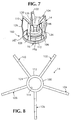
- the spring device 14 is preferably formed of metal such as stainless steel and can be stamped as a one-piece flat structure as shown in Fig. 8 and then bent to the desired form.
- the spring device 14 in blank form is preferably approximately .007 inches thick and has an annular base portion 100.
- Equally spaced spring arms 102, 104, 106, 108 and 110 extend upwardly from an outer peripheral edge 112 of the annular base portion 100.
- the spring arms 102-110 each include a radially outer section 116 (Fig. 6) and a radially inner section 118 joined by a bent over portion 120.
- the radially outer section 116 has a bottom end 124 at the annular base 100 and an intermediate bend 126 between the bottom end 124 and the bent over portion 120.
- the radially outer section is considered to extend from the bottom end 124 to the bent over portion 120.
- the radially inner section 118 of the spring arms 102-110 has a downwardly directed free end 130 extended toward the annular base 100 and an intermediate bend 132 between the free end 130 and the bent over portion 120.
- a sample tube engaging portion 136 of the radially inner section 118 between the intermediate bend 132 and the free end 130 is substantially parallel to the central axis 44 of the housing 12 as most clearly shown in Fig. 2.
- the free end 130 is bent slightly away from the central axis 44 of the housing 12 toward the radially outer section 116.
- the radially inner section is considered to extend from the bent over portion 120 to the free end 130.
- the end cap 16 which is preferably formed of metal such as stainless steel includes a base portion 140 with an upwardly projecting hub 144.
- the hub 144 includes a peripheral groove 146 and a reduced diameter hub extension 148 with a rounded concave surface 150.
- the top edge of the hub 144 is chamfered to provide an edge 147 at the peripheral groove 146.
- a central opening 152 if formed in the base portion 140 and extends through the rounded concave surface 150.
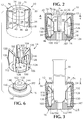
- Assembly of the puck 10 includes locating the annular base 100 of the spring device 14 around the hub 144 of the end cap 16 to form a subassembly 160 as shown in Fig. 7.
- the subassembly 160 is inserted into the lower end 18 of the housing 12.
- the inner diameter 114 (Fig. 8) of the annular base portion 100 of the spring device 14 is sized to snugly fit around the end cap hub 144.
- the subassembly 160 of the spring device 14 and the end cap 16 is then directed into the lower housing end 18 such that the spring arms 102-110 align with and are received in the slots 42 until the annular base 100 of the spring device 14 bottoms against the ends of the inner wall 38 at the lower housing end 18 as shown in Figs. 2 and 3.
- the periphery of the hub 144 is sized to closely engage the inner wall portion 38 of the housing 12 such that the edge 147 presses against the inner wall 38 to provide a press fit of the end cap 16 in the housing 12.
- bonding material can also be provided at the annular base 100 of the spring and in the peripheral groove 146.
- the intermediate bend 126 of the radially outer section 116 of the spring arms 102-110 engage the cylindrical wall 34 within the confines of the slots 42.
- the radially inner sections 118 of the spring arms 102-110 are disposed in the interior space 26 of the housing 12.
- the portions 136 of the radially inner sections 118 are substantially parallel to the central axis 44 of the housing 12, which is also the central axis of the puck 10.
- a sample tube 30 disposed in the puck 10 in the manner shown in Figs. 1 and 3 bottoms against the rounded convex surface 150 of the cap 16 and the wall of the sample tube 30 is contacted by the sample tube engaging portions 136 of the spring arms 102-110. Insertion of the sample tube 30 causes the spring arm portions 136 to deflect away from the central axis 44 while the bend portions 126 of each spring arm 102-110 remains in fixed position against the cylindrical wall 34 within the slots 42.
- the spring arms 102-110 thus exert an optimum biasing or restraining force on the periphery of the sample tube 30 that retains the sample tube 30 within the housing 12 yet permits easy withdrawal of the sample tube 30 from the housing 12 when such removal is desired.
- the puck 10 serves as a carrier for the sample tube 30 when the puck 10 is disposed on a conveyor.
- the end cap 16 provides the puck 10 with sufficient weight to help the puck 10 remain stable on the conveyor while the puck 10 is being transported from one location to another.
- bend angles and size of the spring device 14 and the housing 12 are a matter of choice depending upon the diameter of the sample tube 30 the following magnitudes have been found to provide an optimum retaining force on a sample tube 30 in the diametrical range of approximately 13 mm to 16 mm and a height range of approximately 75 mm to 100 mm.
- the spring arms 102-110 are preferably approximately 1/8 inch wide and have a height of approximately 15/16 inches from the annular base 100 to the bent over portion 120.
- the intermediate bend 126 is formed approximately 1/2 inch from the annular base 100.
- the portion of the radially outer section 116 between the annular base 100 and the intermediate bend 126 is inclined at an angle of approximately 9 degrees away from the vertical toward the cylindrical wall 34 of the housing 12.
- the portion of the radially outer section 116 between the intermediate bend 126 and the bent over portion 120 is inclined approximately 9 degrees toward the central axis 44 of the cylindrical housing 12.
- the portion of the radially inner section 118 between the bent over portion 120 and the intermediate bend 132 is inclined approximately 45 degrees with respect to the vertical and the portion of the radially inner section 118 between the intermediate bend 132 and the free end 130 is inclined toward the central axis of the cylindrical housing 12 by an angle of approximately 5 degrees.
- the distance between the intermediate bend 132 and the free end 130 is approximately 5/16 inches and the distance of the free end 130 from the annular base 100 is approximately 7/16 inches.
- the annular base 100 has an inner diameter of approximately 5/8 inches and an outer diameter of approximately 1 inch.
- the inner diameter of the housing 12 at the cylindrical wall 34 is approximately 1-1/8 inches and the slots 42-50 are approximately 5/32 inches wide.
- the inner diameter of the housing at the inner wall portion 38 is approximately 11/16 inches.
- the housing is approximately 1-3/32 inches in height and has an outside diameter of approximately 1-7/32 inches.
- a puck that contains a one piece spring device that centers and retains a sample tube within the puck interior, a puck that is easy to assemble from three basic component parts that include the housing, the spring device and the end cap, a puck that is capable of retaining sample tubes of different diameters within a predetermined diametrical range and a puck which permits easy release and insertion of sample tubes.
Abstract
Description
- This invention relates to devices for holding an individual container in an upright position while the container is being transported from one location to another, and more particularly to a novel puch for a sample tube.
- Samples of biological materials such as blood, urine or other body fluid that are subject to clinical testing on a massive scale are usually processed in one or more automated apparatus. Various known clinical apparatus can automatically perform such functions as dividing a relatively large sample of body fluid into smaller sized test quantities, mixing a divided sample with an appropriate diluent, and performing a selected test or a series of selected tests on the test sample.
- In some instances it has been found convenient to automatically deliver a sample tube from one location to another for diverse processing and/or test purposes. A commonly used transport device for sample tubes is a conveyor.
- The sample tube, which usually contains a bar code or other indicia capable of automatic identification, is typically disposed in a carrying device such as a puck that is placed on a conveyor. The puck, which includes a receptacle for the sample tube, is intended to stabilize the tube in an upright position during its journey on the conveyor belt to one or more predetermined destinations corresponding to one or more test apparatus. When the puck is at a test apparatus station the sample tube is usually removed from the puck by an automatic handling device such as a robot, which delivers the sample tube to the test apparatus for testing. The empty puck, which normally remains on the conveyor, is automatically reloaded, by a robot, for example, with another sample tube that has completed the test cycle in the test apparatus.
- Since it may be necessary to accomplish rapid removal and insertion of a sample tube in and out of the puck on a frequent basis it is desirable that the puck hold the sample tube with an optimum retaining force that permits easy removal and insertion of the sample tube in and out of the puck.
- Among the several objects of the invention may be noted the provision of a novel puck for a sample tube, a novel puck for a sample tube that centers the sample tube in the puck for convenient insertion and removal of the sample tube from the puck, a novel puck for a sample tube that holds the sample tube with an optimum retaining force that permits easy insertion and removal of the sample tube from the puck, a novel puck for a sample tube having a one piece spring device that facilitates construction and assembly of the puck, a novel puck for a sample tube having a novel spring that centers the sample tube within the puck housing, a novel puck for a sample tube with a spring device having spring arms that are deflectable toward and away from the axis of the puck and a novel puck that can accommodate sample tubes of different diameter within a predetermined size range.
- Other objects and features of the invention will be in part apparent and in part pointed out hereinafter.
- In accordance with the invention the puck includes a generally cylindrical housing having a tube receiving opening at one end to provide access to the interior space of the housing and an end cap at the opposite end of the housing. A spring device is supported on the end cap which locks the spring in the housing. The spring device is preferably a one piece structure and has an annular base portion, with the spring arms extending upwardly from the base portion toward the sample tube receiving opening of the housing. The spring arms are radially spaced around the interior of the housing at substantially equal angles and include radially outer and inner sections with respect to a central axis of the housing. The radially outer sections of the spring arms project upwardly from the end cap toward the tube receiving opening and the radially inner sections of the spring arms are bent over to extend downwardly toward the end cap. The radially inner section of each spring arm includes a sample tube engaging portion that is substantially parallel with the central axis of the housing to engage sample tubes that are disposed within the housing. The sample tube engaging portions are substantially equally spaced from the central axis.
- Slots formed in an inner wall of the housing receive the radially outer sections of the spring arms, whereas the radially inner sections of the spring arms are disposed in the interior space of the housing.
- The end cap constitutes the base of the puck and provides necessary bottom weight to help keep the puck in an upright position. The end cap includes a hub portion on which the annular base portion of the spring device is mounted. The end cap is pressed into one end of the housing with the annular base portion of the spring device being sandwiched between the end cap and a recessed end portion of the inner wall of the housing.
- When a sample tube is disposed in the puck the peripheral surface of the sample tube contacts and deflects the sample tube engaging portion of the spring arm. Selected other portions of the spring arm that do not engage the sample tube are likewise deflectable away from the central axis of the housing in response to insertion of the sample tube. In this manner the deflection of the spring arms provide a biasing force against the sample tube that is sufficient to hold the tube in the housing yet permit easy withdrawal of the tube from the puck when such withdrawal is desired. The sample tube engaging portions of the spring arms also center the tube in the puck.
- The invention accordingly comprises the constructions hereinafter described, the scope of the invention being indicated in the claims.
- In the drawings:
- Fig. 1 is a simplified perspective view of a puck incorporating the present invention prior to receiving a sample tube;
- Fig. 2 is a sectional view, in elevation of the puck;
- Fig. 3 is a view similar to Fig. 2, with the sample tube inserted in the puck;
- Fig. 4 is a sectional view taken on the line 4-4 of Fig. 2;
- Fig. 5 is a sectional view thereof taken on the line 5-5 of Fig. 3;
- Fig. 6 is an exploded view of the puck components;
- Fig. 7 is a perspective view of the spring device and cap thereof in the form of a subassembly; and
- Fig. 8 is a developmental plan view of the spring device.
-
- Corresponding reference characters indicate corresponding parts throughout the several views of the drawings.
- A puck incorporating one embodiment of the invention is generally indicated by the
reference number 10. - Referring to Figs. 2 and 6, the
puck 10 includes a generallycylindrical housing 12, aspring device 14 disposed in the housing and anend cap 16 provided at alower end 18 of the housing. An oppositeupper end 20 of the housing has a tube receiving opening 22 that provides access to aninterior space 26 of the housing which accommodates asample tube 30. - The
housing 12 is formed of plastic, preferably an acetal resin, having an outsidecylindrical wall 34 extending from thelower housing end 18 to theupper housing end 20. Thehousing 12 further includes aninner wall portion 38 spaced from the cylindrical wall 34 (Fig. 4). Theinner wall portion 38 defines theinterior space 26 of the housing and contains fiveslots 42, equally spaced approximately 72 degrees around a central axis 44 (Fig. 1) of thehousing 12. Theslots 42 have a radial extent from theinner wall portion 38 to thecylindrical wall 34 and a length that runs from slightly within thelower housing end 18 to theupper housing end 20. Theslots 42 are open at thelower housing end 18 as indicated by reference number 46 (Fig. 6) and haveslot side walls - Hollow spaces 62 (Fig. 4) between the
inner wall portion 38 and thecylindrical wall 34 are open at thehousing end 18. Thehousing 12 is preferably molded andejector pin pads 66 are preferably provided in thehollow spaces 62 on the inside of the inner wall portion 38 (Fig.4). - The
cylindrical wall 34 extends slightly beyond the open ends of theslots 42 and thehollow spaces 62 at thelower housing end 18 as indicated by the reference number 68 (Fig. 6). An upperannular base portion 74 at theupper housing end 20 closes off theslots 42 and thehollow spaces 62. The upperannular base portion 74 has an innercircumferential edge 76 of slightly smaller diameter than the diameter of theinner wall portion 38 so as to define a small ledge 78. The ledge 78 helps to keep an insertedsample tube 30 away from theinner wall portion 38 as the sample tube enters the tube receiving opening 22 of thehousing 12. - The
spring device 14 is preferably formed of metal such as stainless steel and can be stamped as a one-piece flat structure as shown in Fig. 8 and then bent to the desired form. Thespring device 14 in blank form is preferably approximately .007 inches thick and has anannular base portion 100. Equally spacedspring arms peripheral edge 112 of theannular base portion 100. The spring arms 102-110 each include a radially outer section 116 (Fig. 6) and a radiallyinner section 118 joined by a bent overportion 120. - The radially
outer section 116 has abottom end 124 at theannular base 100 and anintermediate bend 126 between thebottom end 124 and the bent overportion 120. The radially outer section is considered to extend from thebottom end 124 to the bent overportion 120. - The radially
inner section 118 of the spring arms 102-110 has a downwardly directedfree end 130 extended toward theannular base 100 and anintermediate bend 132 between thefree end 130 and the bent overportion 120. A sampletube engaging portion 136 of the radiallyinner section 118 between theintermediate bend 132 and thefree end 130 is substantially parallel to thecentral axis 44 of thehousing 12 as most clearly shown in Fig. 2. Thefree end 130 is bent slightly away from thecentral axis 44 of thehousing 12 toward the radiallyouter section 116. The radially inner section is considered to extend from the bent overportion 120 to thefree end 130. - The end cap 16 (Fig. 6) which is preferably formed of metal such as stainless steel includes a
base portion 140 with an upwardly projectinghub 144. Thehub 144 includes aperipheral groove 146 and a reduceddiameter hub extension 148 with a roundedconcave surface 150. The top edge of thehub 144 is chamfered to provide anedge 147 at theperipheral groove 146. Acentral opening 152 if formed in thebase portion 140 and extends through the roundedconcave surface 150. - Assembly of the
puck 10 includes locating theannular base 100 of thespring device 14 around thehub 144 of theend cap 16 to form asubassembly 160 as shown in Fig. 7. Thesubassembly 160 is inserted into thelower end 18 of thehousing 12. - It will be noted that the inner diameter 114 (Fig. 8) of the
annular base portion 100 of thespring device 14 is sized to snugly fit around theend cap hub 144. Thesubassembly 160 of thespring device 14 and theend cap 16 is then directed into thelower housing end 18 such that the spring arms 102-110 align with and are received in theslots 42 until theannular base 100 of thespring device 14 bottoms against the ends of theinner wall 38 at thelower housing end 18 as shown in Figs. 2 and 3. - The periphery of the
hub 144 is sized to closely engage theinner wall portion 38 of thehousing 12 such that theedge 147 presses against theinner wall 38 to provide a press fit of theend cap 16 in thehousing 12. If desired bonding material can also be provided at theannular base 100 of the spring and in theperipheral groove 146. Under this arrangement theintermediate bend 126 of the radiallyouter section 116 of the spring arms 102-110 engage thecylindrical wall 34 within the confines of theslots 42. The radiallyinner sections 118 of the spring arms 102-110 are disposed in theinterior space 26 of thehousing 12. Theportions 136 of the radiallyinner sections 118 are substantially parallel to thecentral axis 44 of thehousing 12, which is also the central axis of thepuck 10. - A
sample tube 30 disposed in thepuck 10 in the manner shown in Figs. 1 and 3 bottoms against the roundedconvex surface 150 of thecap 16 and the wall of thesample tube 30 is contacted by the sampletube engaging portions 136 of the spring arms 102-110. Insertion of thesample tube 30 causes thespring arm portions 136 to deflect away from thecentral axis 44 while thebend portions 126 of each spring arm 102-110 remains in fixed position against thecylindrical wall 34 within theslots 42. The spring arms 102-110 thus exert an optimum biasing or restraining force on the periphery of thesample tube 30 that retains thesample tube 30 within thehousing 12 yet permits easy withdrawal of thesample tube 30 from thehousing 12 when such removal is desired. - In this manner, the
puck 10 serves as a carrier for thesample tube 30 when thepuck 10 is disposed on a conveyor. Theend cap 16 provides thepuck 10 with sufficient weight to help thepuck 10 remain stable on the conveyor while thepuck 10 is being transported from one location to another. - Although the bend angles and size of the
spring device 14 and thehousing 12 are a matter of choice depending upon the diameter of thesample tube 30 the following magnitudes have been found to provide an optimum retaining force on asample tube 30 in the diametrical range of approximately 13 mm to 16 mm and a height range of approximately 75 mm to 100 mm. - The spring arms 102-110 are preferably approximately 1/8 inch wide and have a height of approximately 15/16 inches from the
annular base 100 to the bent overportion 120. Theintermediate bend 126 is formed approximately 1/2 inch from theannular base 100. The portion of the radiallyouter section 116 between theannular base 100 and theintermediate bend 126 is inclined at an angle of approximately 9 degrees away from the vertical toward thecylindrical wall 34 of thehousing 12. - The portion of the radially
outer section 116 between theintermediate bend 126 and the bent overportion 120 is inclined approximately 9 degrees toward thecentral axis 44 of thecylindrical housing 12. The portion of the radiallyinner section 118 between the bent overportion 120 and theintermediate bend 132 is inclined approximately 45 degrees with respect to the vertical and the portion of the radiallyinner section 118 between theintermediate bend 132 and thefree end 130 is inclined toward the central axis of thecylindrical housing 12 by an angle of approximately 5 degrees. The distance between theintermediate bend 132 and thefree end 130 is approximately 5/16 inches and the distance of thefree end 130 from theannular base 100 is approximately 7/16 inches. Theannular base 100 has an inner diameter of approximately 5/8 inches and an outer diameter of approximately 1 inch. - The inner diameter of the
housing 12 at thecylindrical wall 34 is approximately 1-1/8 inches and the slots 42-50 are approximately 5/32 inches wide. The inner diameter of the housing at theinner wall portion 38 is approximately 11/16 inches. The housing is approximately 1-3/32 inches in height and has an outside diameter of approximately 1-7/32 inches. - Some advantages of the invention evident from the foregoing description include a puck that contains a one piece spring device that centers and retains a sample tube within the puck interior, a puck that is easy to assemble from three basic component parts that include the housing, the spring device and the end cap, a puck that is capable of retaining sample tubes of different diameters within a predetermined diametrical range and a puck which permits easy release and insertion of sample tubes.
- In view of the above, it will be seen that the several objects of the invention are achieved and other advantageous results attained.
- As various changes can be made in the above constructions without departing from the scope of the invention, it is intended that all matter contained in the above description or shown in the accompanying drawings shall be interpreted as illustrative and not in a limiting sense.
Claims (10)
- A puck comprising,a) a generally cylindrical housing having a central axis and a tube receiving opening at one end of the housing to provide access to an interior space of the housing and an end cap at the opposite end of the housing, andb) a one piece spring supported on said end cap and having a plurality of spring arms projecting upwardly from said end cap toward the tube receiving opening, said spring arms being angularly spaced around the interior space of said housing.
- The puck as claimed in claim 1 wherein said spring arms include a radially outer section with respect to said central axis, and a radially inner section with respect to said central axis, said radially inner and outer sections being joined by a bent over portion of said spring arms.
- The puck as claimed in claim 2 wherein said radially inner section includes a free end directed downwardly toward said end cap.
- The puck as claimed in claim 3 wherein said housing includes an inner wall portion, the radially outer section of said spring arm being recessed in said inner wall portion and the radially inner section of said spring arm extending within the interior space of said housing.
- The puck as claimed in claim 2 wherein said radially inner section of said spring arm has a free end directed downwardly toward said end cap, said radially inner section extending from said bent over portion to said free end.
- The puck as claimed in claim 1 wherein said spring includes a circular base portion and said spring arms extend upwardly from said circular base portion.
- The puck as claimed in claim 1 wherein said housing includes an inner wall portion defining the interior space of said housing and a predetermined number of slots in said inner wall portion.
- The puck as claimed in claim 1 wherein said end cap includes a central opening.
- The puck as claimed in claim 1 wherein said end cap includes a hub portion projecting into the interior space of said housing for press fitting engagement with said housing.
- The puck as claimed in claim 9 wherein said spring includes an annular base portion sized to fit around said hub portion.
Priority Applications (1)
| Application Number | Priority Date | Filing Date | Title |
|---|---|---|---|
| DK98121459T DK0916406T3 (en) | 1997-11-13 | 1998-11-11 | Puck for test glass |
Applications Claiming Priority (2)
| Application Number | Priority Date | Filing Date | Title |
|---|---|---|---|
| US08/969,510 US5897090A (en) | 1997-11-13 | 1997-11-13 | Puck for a sample tube |
| US969510 | 1997-11-13 |
Publications (3)
| Publication Number | Publication Date |
|---|---|
| EP0916406A2 true EP0916406A2 (en) | 1999-05-19 |
| EP0916406A3 EP0916406A3 (en) | 2000-01-19 |
| EP0916406B1 EP0916406B1 (en) | 2004-08-11 |
Family
ID=25515647
Family Applications (1)
| Application Number | Title | Priority Date | Filing Date |
|---|---|---|---|
| EP98121459A Expired - Lifetime EP0916406B1 (en) | 1997-11-13 | 1998-11-11 | Puck for a sample tube |
Country Status (7)
| Country | Link |
|---|---|
| US (1) | US5897090A (en) |
| EP (1) | EP0916406B1 (en) |
| JP (1) | JPH11218537A (en) |
| AT (1) | ATE273076T1 (en) |
| CA (1) | CA2248425A1 (en) |
| DE (1) | DE69825544D1 (en) |
| DK (1) | DK0916406T3 (en) |
Cited By (87)
| Publication number | Priority date | Publication date | Assignee | Title |
|---|---|---|---|---|
| WO2002026386A2 (en) * | 2000-09-29 | 2002-04-04 | Avantium International B.V. | Assembly of an integrated vessel transporter and at least one reaction vessel for transporting a chemical substance |
| WO2002082095A1 (en) * | 2001-04-03 | 2002-10-17 | Thermo Clinical Labsystems Oy | Test tube carrier |
| WO2005087628A1 (en) * | 2004-03-11 | 2005-09-22 | Philip Sheets | A process and a device for conveying odd-shaped containers |
| WO2008043394A1 (en) * | 2006-10-11 | 2008-04-17 | Inpeco Ip Ltd. | Specimen container carrier for conveyor in laboratory automation system |
| DE202006020672U1 (en) | 2005-02-01 | 2009-08-06 | Stiwa-Fertigungstechnik Sticht Ges.M.B.H. | Holding device for cylindrical objects, in particular tubular sample containers |
| US7726106B2 (en) | 2003-07-30 | 2010-06-01 | Graham Packaging Co | Container handling system |
| US7799264B2 (en) | 2006-03-15 | 2010-09-21 | Graham Packaging Company, L.P. | Container and method for blowmolding a base in a partial vacuum pressure reduction setup |
| US7900425B2 (en) | 2005-10-14 | 2011-03-08 | Graham Packaging Company, L.P. | Method for handling a hot-filled container having a moveable portion to reduce a portion of a vacuum created therein |
| US7926243B2 (en) | 2009-01-06 | 2011-04-19 | Graham Packaging Company, L.P. | Method and system for handling containers |
| US7980404B2 (en) | 2001-04-19 | 2011-07-19 | Graham Packaging Company, L.P. | Multi-functional base for a plastic, wide-mouth, blow-molded container |
| US8017065B2 (en) | 2006-04-07 | 2011-09-13 | Graham Packaging Company L.P. | System and method for forming a container having a grip region |
| WO2011132037A1 (en) * | 2010-04-21 | 2011-10-27 | Colepccl Portugal - Embalagens E Enchimentos, S.A. | Holder for generally cylindrical containers |
| US8075833B2 (en) | 2005-04-15 | 2011-12-13 | Graham Packaging Company L.P. | Method and apparatus for manufacturing blow molded containers |
| DE202012100510U1 (en) * | 2012-02-15 | 2012-03-16 | Glp Systems Gmbh | Holder for cylindrical or conical vessels |
| US8627944B2 (en) | 2008-07-23 | 2014-01-14 | Graham Packaging Company L.P. | System, apparatus, and method for conveying a plurality of containers |
| US8636944B2 (en) | 2008-12-08 | 2014-01-28 | Graham Packaging Company L.P. | Method of making plastic container having a deep-inset base |
| US8747727B2 (en) | 2006-04-07 | 2014-06-10 | Graham Packaging Company L.P. | Method of forming container |
| CN104024863A (en) * | 2011-12-28 | 2014-09-03 | 株式会社日立高新技术 | Holder for transferring test tube |
| US8919587B2 (en) | 2011-10-03 | 2014-12-30 | Graham Packaging Company, L.P. | Plastic container with angular vacuum panel and method of same |
| US8962114B2 (en) | 2010-10-30 | 2015-02-24 | Graham Packaging Company, L.P. | Compression molded preform for forming invertible base hot-fill container, and systems and methods thereof |
| US9022776B2 (en) | 2013-03-15 | 2015-05-05 | Graham Packaging Company, L.P. | Deep grip mechanism within blow mold hanger and related methods and bottles |
| US9150320B2 (en) | 2011-08-15 | 2015-10-06 | Graham Packaging Company, L.P. | Plastic containers having base configurations with up-stand walls having a plurality of rings, and systems, methods, and base molds thereof |
| EP2908139A3 (en) * | 2014-02-17 | 2015-11-11 | Roche Diagniostics GmbH | Transport device, sample distribution system and laboratory automation system |
| US9239335B2 (en) | 2011-11-04 | 2016-01-19 | Roche Diagnostics Operations, Inc. | Laboratory sample distribution system, laboratory system and method of operating |
| EP2949392A3 (en) * | 2014-05-09 | 2016-02-24 | Euroimmun Medizinische Labordiagnostika AG | Reagent bottle shading device and analysis device |
| US9423411B2 (en) | 2014-02-17 | 2016-08-23 | Roche Diagnostics Operations, Inc. | Transport device, sample distribution system and laboratory automation system |
| EP3093071A1 (en) | 2015-05-11 | 2016-11-16 | Roche Diagniostics GmbH | Test tube carrier |
| US9567167B2 (en) | 2014-06-17 | 2017-02-14 | Roche Diagnostics Operations, Inc. | Laboratory sample distribution system and laboratory automation system |
| US9593970B2 (en) | 2014-09-09 | 2017-03-14 | Roche Diagnostics Operations, Inc. | Laboratory sample distribution system and method for calibrating magnetic sensors |
| US9598243B2 (en) | 2011-11-04 | 2017-03-21 | Roche Diagnostics Operations, Inc. | Laboratory sample distribution system and corresponding method of operation |
| US9618525B2 (en) | 2014-10-07 | 2017-04-11 | Roche Diagnostics Operations, Inc. | Module for a laboratory sample distribution system, laboratory sample distribution system and laboratory automation system |
| US9624018B2 (en) | 2002-09-30 | 2017-04-18 | Co2 Pac Limited | Container structure for removal of vacuum pressure |
| US9658241B2 (en) | 2014-03-31 | 2017-05-23 | Roche Diagnostics Operations, Inc. | Sample distribution system and laboratory automation system |
| US9664703B2 (en) | 2011-11-04 | 2017-05-30 | Roche Diagnostics Operations, Inc. | Laboratory sample distribution system and corresponding method of operation |
| US9707711B2 (en) | 2006-04-07 | 2017-07-18 | Graham Packaging Company, L.P. | Container having outwardly blown, invertible deep-set grips |
| EP3211427A1 (en) | 2016-02-25 | 2017-08-30 | Roche Diagnostics GmbH | Sample container carrier |
| EP3211426A1 (en) | 2016-02-25 | 2017-08-30 | Roche Diagnostics GmbH | Sample container carrier |
| US9772342B2 (en) | 2014-03-31 | 2017-09-26 | Roche Diagnostics Operations, Inc. | Dispatching device, sample distribution system and laboratory automation system |
| US9791468B2 (en) | 2014-03-31 | 2017-10-17 | Roche Diagnostics Operations, Inc. | Transport device, sample distribution system and laboratory automation system |
| US9802730B2 (en) | 2002-09-30 | 2017-10-31 | Co2 Pac Limited | Methods of compensating for vacuum pressure changes within a plastic container |
| US9810706B2 (en) | 2014-03-31 | 2017-11-07 | Roche Diagnostics Operations, Inc. | Vertical conveying device, laboratory sample distribution system and laboratory automation system |
| US9902572B2 (en) | 2015-10-06 | 2018-02-27 | Roche Diagnostics Operations, Inc. | Method of configuring a laboratory automation system, laboratory sample distribution system and laboratory automation system |
| US9939455B2 (en) | 2014-11-03 | 2018-04-10 | Roche Diagnostics Operations, Inc. | Laboratory sample distribution system and laboratory automation system |
| US9952242B2 (en) | 2014-09-12 | 2018-04-24 | Roche Diagnostics Operations, Inc. | Laboratory sample distribution system and laboratory automation system |
| US9969517B2 (en) | 2002-09-30 | 2018-05-15 | Co2Pac Limited | Systems and methods for handling plastic containers having a deep-set invertible base |
| US9969570B2 (en) | 2010-05-07 | 2018-05-15 | Roche Diagnostics Operations, Inc. | System for transporting containers between different stations and a container carrier |
| US9989547B2 (en) | 2014-07-24 | 2018-06-05 | Roche Diagnostics Operations, Inc. | Laboratory sample distribution system and laboratory automation system |
| US9993959B2 (en) | 2013-03-15 | 2018-06-12 | Graham Packaging Company, L.P. | Deep grip mechanism for blow mold and related methods and bottles |
| US9994378B2 (en) | 2011-08-15 | 2018-06-12 | Graham Packaging Company, L.P. | Plastic containers, base configurations for plastic containers, and systems, methods, and base molds thereof |
| US10006927B2 (en) | 2015-05-22 | 2018-06-26 | Roche Diagnostics Operations, Inc. | Method of operating a laboratory automation system and a laboratory automation system |
| US10012666B2 (en) | 2014-03-31 | 2018-07-03 | Roche Diagnostics Operations, Inc. | Sample distribution system and laboratory automation system |
| US10094843B2 (en) | 2015-03-23 | 2018-10-09 | Roche Diagnostics Operations, Inc. | Laboratory sample distribution system and laboratory automation system |
| US10119982B2 (en) | 2015-03-16 | 2018-11-06 | Roche Diagnostics Operations, Inc. | Transport carrier, laboratory cargo distribution system, and laboratory automation system |
| US10160609B2 (en) | 2015-10-13 | 2018-12-25 | Roche Diagnostics Operations, Inc. | Laboratory sample distribution system and laboratory automation system |
| US10175259B2 (en) | 2015-09-01 | 2019-01-08 | Roche Diagnostics Operations, Inc. | Laboratory cargo distribution system, laboratory automation system and method of operating a laboratory cargo distribution system |
| US10197555B2 (en) | 2016-06-21 | 2019-02-05 | Roche Diagnostics Operations, Inc. | Method of setting a handover position and laboratory automation system |
| US10197586B2 (en) | 2015-10-06 | 2019-02-05 | Roche Diagnostics Operations, Inc. | Method of determining a handover position and laboratory automation system |
| US10214407B2 (en) | 2010-10-31 | 2019-02-26 | Graham Packaging Company, L.P. | Systems for cooling hot-filled containers |
| US10228384B2 (en) | 2015-10-14 | 2019-03-12 | Roche Diagnostics Operations, Inc. | Method of rotating a sample container carrier, laboratory sample distribution system and laboratory automation system |
| US10239708B2 (en) | 2014-09-09 | 2019-03-26 | Roche Diagnostics Operations, Inc. | Laboratory sample distribution system and laboratory automation system |
| US10246238B2 (en) | 2000-08-31 | 2019-04-02 | Co2Pac Limited | Plastic container having a deep-set invertible base and related methods |
| US10352953B2 (en) | 2015-05-22 | 2019-07-16 | Roche Diagnostics Operations, Inc. | Method of operating a laboratory sample distribution system, laboratory sample distribution system and a laboratory automation system |
| US10416183B2 (en) | 2016-12-01 | 2019-09-17 | Roche Diagnostics Operations, Inc. | Laboratory sample distribution system and laboratory automation system |
| US10436808B2 (en) | 2016-12-29 | 2019-10-08 | Roche Diagnostics Operations, Inc. | Laboratory sample distribution system and laboratory automation system |
| US10495657B2 (en) | 2017-01-31 | 2019-12-03 | Roche Diagnostics Operations, Inc. | Laboratory sample distribution system and laboratory automation system |
| US10509049B2 (en) | 2014-09-15 | 2019-12-17 | Roche Diagnostics Operations, Inc. | Method of operating a laboratory sample distribution system, laboratory sample distribution system and laboratory automation system |
| US10520520B2 (en) | 2016-02-26 | 2019-12-31 | Roche Diagnostics Operations, Inc. | Transport device with base plate modules |
| US10564170B2 (en) | 2015-07-22 | 2020-02-18 | Roche Diagnostics Operations, Inc. | Sample container carrier, laboratory sample distribution system and laboratory automation system |
| US10578632B2 (en) | 2016-02-26 | 2020-03-03 | Roche Diagnostics Operations, Inc. | Transport device unit for a laboratory sample distribution system |
| US10605819B2 (en) | 2016-02-26 | 2020-03-31 | Roche Diagnostics Operations, Inc. | Transport device having a tiled driving surface |
| US10836552B2 (en) | 2007-02-09 | 2020-11-17 | Co2Pac Limited | Method of handling a plastic container having a moveable base |
| US10962557B2 (en) | 2017-07-13 | 2021-03-30 | Roche Diagnostics Operations, Inc. | Method of operating a laboratory sample distribution system, laboratory sample distribution system and laboratory automation system |
| US10989725B2 (en) | 2017-06-02 | 2021-04-27 | Roche Diagnostics Operations, Inc. | Method of operating a laboratory sample distribution system, laboratory sample distribution system, and laboratory automation system |
| US10989726B2 (en) | 2016-06-09 | 2021-04-27 | Roche Diagnostics Operations, Inc. | Laboratory sample distribution system and method of operating a laboratory sample distribution system |
| US10996233B2 (en) | 2016-06-03 | 2021-05-04 | Roche Diagnostics Operations, Inc. | Laboratory sample distribution system and laboratory automation system |
| US11092613B2 (en) | 2015-05-22 | 2021-08-17 | Roche Diagnostics Operations, Inc. | Method of operating a laboratory sample distribution system, laboratory sample distribution system and laboratory automation system |
| US11112421B2 (en) | 2016-08-04 | 2021-09-07 | Roche Diagnostics Operations, Inc. | Laboratory sample distribution system and laboratory automation system |
| US11110464B2 (en) | 2017-09-13 | 2021-09-07 | Roche Diagnostics Operations, Inc. | Sample container carrier, laboratory sample distribution system and laboratory automation system |
| US11110463B2 (en) | 2017-09-13 | 2021-09-07 | Roche Diagnostics Operations, Inc. | Sample container carrier, laboratory sample distribution system and laboratory automation system |
| US11204361B2 (en) | 2017-02-03 | 2021-12-21 | Roche Diagnostics Operations, Inc. | Laboratory automation system |
| US11226348B2 (en) | 2015-07-02 | 2022-01-18 | Roche Diagnostics Operations, Inc. | Storage module, method of operating a laboratory automation system and laboratory automation system |
| WO2022189427A1 (en) * | 2021-03-12 | 2022-09-15 | Aesculap Ag | Expanding holder and tool set |
| US11709171B2 (en) | 2018-03-16 | 2023-07-25 | Roche Diagnostics Operations, Inc. | Laboratory system, laboratory sample distribution system and laboratory automation system |
| US11731823B2 (en) | 2007-02-09 | 2023-08-22 | Co2Pac Limited | Method of handling a plastic container having a moveable base |
| US11747356B2 (en) | 2020-12-21 | 2023-09-05 | Roche Diagnostics Operations, Inc. | Support element for a modular transport plane, modular transport plane, and laboratory distribution system |
| US11897656B2 (en) | 2007-02-09 | 2024-02-13 | Co2Pac Limited | Plastic container having a movable base |
| US11971420B2 (en) | 2018-03-07 | 2024-04-30 | Roche Diagnostics Operations, Inc. | Method of operating a laboratory sample distribution system, laboratory sample distribution system and laboratory automation system |
Families Citing this family (74)
| Publication number | Priority date | Publication date | Assignee | Title |
|---|---|---|---|---|
| WO1999065778A2 (en) * | 1998-06-18 | 1999-12-23 | Hoppmann Corporation | Can assembly system |
| US8360379B2 (en) * | 1999-07-16 | 2013-01-29 | Porcelli Joseph E | Car and truck beverage holder |
| US6170787B1 (en) * | 1999-07-29 | 2001-01-09 | Club Car, Inc. | Expandable cup holder for a vehicle |
| FI20000492A0 (en) * | 2000-03-03 | 2000-03-03 | Labsystems Oy | Absorbance measurement |
| US10435223B2 (en) | 2000-08-31 | 2019-10-08 | Co2Pac Limited | Method of handling a plastic container having a moveable base |
| US8127955B2 (en) | 2000-08-31 | 2012-03-06 | John Denner | Container structure for removal of vacuum pressure |
| TWI228476B (en) * | 2000-08-31 | 2005-03-01 | Co2 Pac Ltd | Semi-rigid collapsible container |
| US8584879B2 (en) * | 2000-08-31 | 2013-11-19 | Co2Pac Limited | Plastic container having a deep-set invertible base and related methods |
| CA2444041A1 (en) | 2001-04-19 | 2002-10-31 | Graham Packaging Company, L.P. | Multi-functional base for a plastic wide-mouth, blow-molded container |
| EP1409138B1 (en) * | 2001-07-20 | 2010-09-01 | Gen-Probe Incorporated Patent Dept | Sample carrier and drip shield for use therewith |
| US20030155274A1 (en) * | 2002-02-15 | 2003-08-21 | Peter Rosler | End cap with springed ribs for packaging objects |
| US7276208B2 (en) * | 2002-05-17 | 2007-10-02 | Gen-Probe Incorporated | Sample carrier having sample tube blocking member |
| JP4235170B2 (en) * | 2002-05-17 | 2009-03-11 | ジェン−プロウブ インコーポレイテッド | Sample carrier with detachable locking mechanism |
| DE20208253U1 (en) * | 2002-05-28 | 2003-10-09 | Fischer Automotive Sys Gmbh | Holder for a beverage container |
| US6585210B1 (en) * | 2002-06-19 | 2003-07-01 | Super Link Electronics Co., Ltd. | Secure pen holding mechanism |
| DE20218745U1 (en) * | 2002-12-04 | 2004-04-08 | Fischer Automotive Systems Gmbh | Holder for a beverage container |
| DE20219606U1 (en) * | 2002-12-18 | 2004-04-29 | Fischer Automotive Systems Gmbh | Holder for a beverage container |
| US6922153B2 (en) * | 2003-05-13 | 2005-07-26 | Credo Technology Corporation | Safety detection and protection system for power tools |
| JP4056982B2 (en) * | 2004-03-17 | 2008-03-05 | 株式会社アイディエス | Test tube holder |
| US7234673B2 (en) * | 2004-04-30 | 2007-06-26 | Salus Corporation | Wall mounted bracket system |
| US20060133963A1 (en) * | 2004-12-16 | 2006-06-22 | Israel Stein | Adapter for attaching information to test tubes |
| US7910067B2 (en) | 2005-04-19 | 2011-03-22 | Gen-Probe Incorporated | Sample tube holder |
| DE102005060439B3 (en) * | 2005-12-17 | 2007-06-06 | Rösler, Peter | Packaging container with clamping base |
| US20090095865A1 (en) * | 2006-05-01 | 2009-04-16 | Cornerstone Research Group, Inc. | Device for Securely Holding Objects in Place |
| US20090028754A1 (en) * | 2007-07-27 | 2009-01-29 | Dade Behring Inc. | Insert for Restraining Tube Rotation in a Sample Tube Rack |
| US8439223B2 (en) * | 2007-08-20 | 2013-05-14 | The Procter & Gamble Company | Base cup for a supportable pressurizable container |
| US20090078710A1 (en) * | 2007-09-21 | 2009-03-26 | Learning Curve Brands, Inc. | Apparatus and method of thawing and warming baby food |
| US7938375B1 (en) * | 2007-12-21 | 2011-05-10 | Casey Massegee | Pen retaining sleeve |
| US8087528B1 (en) | 2008-01-28 | 2012-01-03 | Elizabeth Scarlett | Stabilizer cup holder |
| JP5393255B2 (en) * | 2009-05-22 | 2014-01-22 | 株式会社日立ハイテクノロジーズ | Sample transport system |
| DE102009035694B4 (en) * | 2009-07-30 | 2011-12-22 | F.S. Fehrer Automotive Gmbh | Armrest with drinking vessel holder |
| US8297441B2 (en) * | 2009-08-04 | 2012-10-30 | Pepsico, Inc. | Protective contact strips for beverage trays |
| SE534735C2 (en) | 2009-09-04 | 2011-12-06 | Flexlink Components Ab | Bärarpuck |
| JP4992956B2 (en) * | 2009-11-27 | 2012-08-08 | 豊田合成株式会社 | Cup holder |
| US8132664B2 (en) * | 2010-07-30 | 2012-03-13 | Avantage Puck Technologies, Inc. | Product holding puck with noise reducing bumpers |
| US9144801B2 (en) | 2010-08-31 | 2015-09-29 | Abbott Laboratories | Sample tube racks having retention bars |
| BR112013029217A2 (en) | 2011-05-13 | 2017-01-31 | Beckman Coulter Inc | system and method including a laboratory product transport element |
| WO2012158520A1 (en) | 2011-05-13 | 2012-11-22 | Beckman Coulter, Inc. | Laboratory product transport element and path arrangement |
| US9286914B2 (en) | 2011-06-01 | 2016-03-15 | International Business Machines Corporation | Cartridge for storing biosample capillary tubes and use in automated data storage systems |
| JP6190380B2 (en) | 2011-11-07 | 2017-08-30 | ベックマン コールター, インコーポレイテッド | Equalizer system and workflow |
| BR112014011043A2 (en) | 2011-11-07 | 2017-06-13 | Beckman Coulter Inc | specimen container detection |
| BR112014011046A2 (en) | 2011-11-07 | 2017-06-13 | Beckman Coulter, Inc. | workflow and centrifuge system |
| JP6165755B2 (en) | 2011-11-07 | 2017-07-19 | ベックマン コールター, インコーポレイテッド | Robot arm |
| WO2013070756A2 (en) | 2011-11-07 | 2013-05-16 | Beckman Coulter, Inc. | System and method for processing samples |
| EP2776847A1 (en) | 2011-11-07 | 2014-09-17 | Beckman Coulter, Inc. | Magnetic damping for specimen transport system |
| DE102012100318A1 (en) * | 2012-01-16 | 2013-07-18 | Krones Ag | Carrier element for articles or containers |
| US9844846B2 (en) * | 2012-02-08 | 2017-12-19 | Tension International, Inc. | Container carrier |
| PL2885211T3 (en) | 2012-08-14 | 2019-04-30 | Altria Client Services Llc | Direct to container system with on-line weight control and associated method |
| WO2014043474A1 (en) | 2012-09-14 | 2014-03-20 | Beckman Coulter, Inc. | Analytical system with capillary transport |
| KR101424888B1 (en) * | 2012-09-27 | 2014-07-31 | 현대제철 주식회사 | Sample fixing apparaus of milling machine |
| US9746129B2 (en) | 2012-09-28 | 2017-08-29 | Momentive Performance Materials Inc. | Puck wear detection |
| JP6139232B2 (en) * | 2013-04-12 | 2017-05-31 | 株式会社日立製作所 | Test tube rack |
| US9863970B2 (en) * | 2013-09-03 | 2018-01-09 | Thermo Fisher Scientific Oy | Method and arrangement for handling test tubes |
| US9413062B2 (en) * | 2013-12-07 | 2016-08-09 | Ethertronics, Inc. | Mounting flange for installation of distributed antenna systems |
| CN103657763B (en) * | 2013-12-09 | 2015-06-24 | 山东科技大学 | Water-bath fixing frame with adjustable size |
| US10136754B2 (en) * | 2014-01-17 | 2018-11-27 | Keurig Green Mountain, Inc. | Beverage machine cartridge holder |
| US9295357B2 (en) | 2014-01-17 | 2016-03-29 | Keurig Green Mountain, Inc. | Apparatus for cup and carafe beverage production |
| US9428093B2 (en) * | 2014-06-18 | 2016-08-30 | Toyota Motor Engineering & Manufacturing North America, Inc. | Cup holder assembly having deformable retainer |
| DE102014109197A1 (en) | 2014-07-01 | 2016-01-07 | Aesculap Ag | Storage system for medical instruments |
| JP6601919B2 (en) * | 2014-08-14 | 2019-11-06 | ジェン−プローブ・インコーポレーテッド | Device for removably holding an elongated object in a predetermined orientation and system for transporting an elongated object arranged in a predetermined orientation |
| CN108351363B (en) * | 2015-11-12 | 2021-07-06 | 豪夫迈·罗氏有限公司 | Sample processing device and method for sample processing |
| US10940086B2 (en) * | 2015-11-12 | 2021-03-09 | Scalpal Llc | Bottle support and protective collar |
| US10506890B2 (en) * | 2016-03-11 | 2019-12-17 | Toyoda Gosei Co., Ltd. | Cup holder |
| JP7301265B2 (en) * | 2018-11-21 | 2023-07-03 | パナソニックエナジー株式会社 | Cylinder transport holder |
| FR3080784B1 (en) | 2018-05-07 | 2020-07-31 | Stago Diagnostica | GRIPPING DEVICE FOR A CONTAINER |
| JP7251877B2 (en) * | 2018-06-06 | 2023-04-04 | 積水マテリアルソリューションズ株式会社 | A retainer and a method for manufacturing the retainer. |
| US10773657B2 (en) * | 2018-11-09 | 2020-09-15 | Calsonic Kansei North America, Inc. | Removable electronic device holder |
| GB2583505B (en) | 2019-04-30 | 2021-11-10 | The Unique Puck Company | Multi-functional carrier puck |
| DE102019207307A1 (en) * | 2019-05-20 | 2020-11-26 | Ford Global Technologies, Llc | Universal holder and vehicle interior lining component |
| US10940784B1 (en) * | 2019-09-11 | 2021-03-09 | Ford Global Technologies, Llc | Configurable cup holder assembly |
| CN111804027B (en) * | 2020-08-31 | 2021-03-16 | 余裕敏 | Sediment filtering device with movable filter bag and using method thereof |
| US11071401B1 (en) * | 2021-01-18 | 2021-07-27 | David Krueger | Rolling drink coasters |
| JP7471037B2 (en) * | 2021-02-04 | 2024-04-19 | 株式会社日立製作所 | Tube transport rack |
| CN114624430A (en) * | 2022-02-12 | 2022-06-14 | 王娜娜 | Full-automatic biochemical analyzer |
Citations (5)
| Publication number | Priority date | Publication date | Assignee | Title |
|---|---|---|---|---|
| US3390891A (en) * | 1966-02-25 | 1968-07-02 | Karlsruhe Augsburg Iweka | Tube holder for tube filling and closing machines |
| US4958667A (en) * | 1989-07-17 | 1990-09-25 | R. A. Jones & Co., Inc. | Tube holder for tube filling machines |
| US5014868A (en) * | 1986-04-08 | 1991-05-14 | Ccl Custom Manufacturing, Inc. | Holding device for containers |
| US5154380A (en) * | 1990-08-31 | 1992-10-13 | Mihai Risca | Container holder |
| WO1994000238A1 (en) * | 1992-06-29 | 1994-01-06 | Baxter Diagnostics Inc. | Sample tube carrier |
Family Cites Families (8)
| Publication number | Priority date | Publication date | Assignee | Title |
|---|---|---|---|---|
| US143417A (en) * | 1873-10-07 | Improvement in whip-sockets | ||
| US1351007A (en) * | 1919-02-19 | 1920-08-24 | Shephard Samuel Tuttle | Display-stand |
| US2337914A (en) * | 1941-12-06 | 1943-12-28 | Roy W Meldrum | Christmas tree stand |
| US2647712A (en) * | 1950-04-24 | 1953-08-04 | Sandmoen Richard | Level holder |
| US3671004A (en) * | 1970-09-04 | 1972-06-20 | Design Creations Inc | Hanger for material in sheet form |
| US3918920A (en) * | 1974-01-07 | 1975-11-11 | Beckman Instruments Inc | Holder for sample containers of different sizes |
| US4729413A (en) * | 1986-11-06 | 1988-03-08 | General Electric Company | Transport puck and method to fill caulking cartridges |
| US5484052A (en) * | 1994-05-06 | 1996-01-16 | Dowbrands L.P. | Carrier puck |
-
1997
- 1997-11-13 US US08/969,510 patent/US5897090A/en not_active Expired - Lifetime
-
1998
- 1998-09-25 CA CA002248425A patent/CA2248425A1/en not_active Abandoned
- 1998-11-05 JP JP10328786A patent/JPH11218537A/en active Pending
- 1998-11-11 DK DK98121459T patent/DK0916406T3/en active
- 1998-11-11 AT AT98121459T patent/ATE273076T1/en not_active IP Right Cessation
- 1998-11-11 EP EP98121459A patent/EP0916406B1/en not_active Expired - Lifetime
- 1998-11-11 DE DE69825544T patent/DE69825544D1/en not_active Expired - Fee Related
Patent Citations (5)
| Publication number | Priority date | Publication date | Assignee | Title |
|---|---|---|---|---|
| US3390891A (en) * | 1966-02-25 | 1968-07-02 | Karlsruhe Augsburg Iweka | Tube holder for tube filling and closing machines |
| US5014868A (en) * | 1986-04-08 | 1991-05-14 | Ccl Custom Manufacturing, Inc. | Holding device for containers |
| US4958667A (en) * | 1989-07-17 | 1990-09-25 | R. A. Jones & Co., Inc. | Tube holder for tube filling machines |
| US5154380A (en) * | 1990-08-31 | 1992-10-13 | Mihai Risca | Container holder |
| WO1994000238A1 (en) * | 1992-06-29 | 1994-01-06 | Baxter Diagnostics Inc. | Sample tube carrier |
Cited By (133)
| Publication number | Priority date | Publication date | Assignee | Title |
|---|---|---|---|---|
| US10246238B2 (en) | 2000-08-31 | 2019-04-02 | Co2Pac Limited | Plastic container having a deep-set invertible base and related methods |
| WO2002026386A2 (en) * | 2000-09-29 | 2002-04-04 | Avantium International B.V. | Assembly of an integrated vessel transporter and at least one reaction vessel for transporting a chemical substance |
| WO2002026386A3 (en) * | 2000-09-29 | 2002-09-12 | Avantium Int Bv | Assembly of an integrated vessel transporter and at least one reaction vessel for transporting a chemical substance |
| WO2002082095A1 (en) * | 2001-04-03 | 2002-10-17 | Thermo Clinical Labsystems Oy | Test tube carrier |
| US6971506B2 (en) | 2001-04-03 | 2005-12-06 | Thermo Electron Oy | Test tube carrier |
| US8529975B2 (en) | 2001-04-19 | 2013-09-10 | Graham Packaging Company, L.P. | Multi-functional base for a plastic, wide-mouth, blow-molded container |
| US8839972B2 (en) | 2001-04-19 | 2014-09-23 | Graham Packaging Company, L.P. | Multi-functional base for a plastic, wide-mouth, blow-molded container |
| US8381496B2 (en) | 2001-04-19 | 2013-02-26 | Graham Packaging Company Lp | Method of hot-filling a plastic, wide-mouth, blow-molded container having a multi-functional base |
| US7980404B2 (en) | 2001-04-19 | 2011-07-19 | Graham Packaging Company, L.P. | Multi-functional base for a plastic, wide-mouth, blow-molded container |
| US9522749B2 (en) | 2001-04-19 | 2016-12-20 | Graham Packaging Company, L.P. | Method of processing a plastic container including a multi-functional base |
| US9624018B2 (en) | 2002-09-30 | 2017-04-18 | Co2 Pac Limited | Container structure for removal of vacuum pressure |
| US9802730B2 (en) | 2002-09-30 | 2017-10-31 | Co2 Pac Limited | Methods of compensating for vacuum pressure changes within a plastic container |
| US10351325B2 (en) | 2002-09-30 | 2019-07-16 | Co2 Pac Limited | Container structure for removal of vacuum pressure |
| US10315796B2 (en) | 2002-09-30 | 2019-06-11 | Co2 Pac Limited | Pressure reinforced deformable plastic container with hoop rings |
| US9969517B2 (en) | 2002-09-30 | 2018-05-15 | Co2Pac Limited | Systems and methods for handling plastic containers having a deep-set invertible base |
| US9878816B2 (en) | 2002-09-30 | 2018-01-30 | Co2 Pac Ltd | Systems for compensating for vacuum pressure changes within a plastic container |
| US10273072B2 (en) | 2002-09-30 | 2019-04-30 | Co2 Pac Limited | Container structure for removal of vacuum pressure |
| US11377286B2 (en) | 2002-09-30 | 2022-07-05 | Co2 Pac Limited | Container structure for removal of vacuum pressure |
| US10501225B2 (en) | 2003-07-30 | 2019-12-10 | Graham Packaging Company, L.P. | Container handling system |
| US10661939B2 (en) | 2003-07-30 | 2020-05-26 | Co2Pac Limited | Pressure reinforced plastic container and related method of processing a plastic container |
| US8671653B2 (en) | 2003-07-30 | 2014-03-18 | Graham Packaging Company, L.P. | Container handling system |
| US9090363B2 (en) | 2003-07-30 | 2015-07-28 | Graham Packaging Company, L.P. | Container handling system |
| US7735304B2 (en) | 2003-07-30 | 2010-06-15 | Graham Packaging Co | Container handling system |
| US7726106B2 (en) | 2003-07-30 | 2010-06-01 | Graham Packaging Co | Container handling system |
| WO2005087628A1 (en) * | 2004-03-11 | 2005-09-22 | Philip Sheets | A process and a device for conveying odd-shaped containers |
| AU2005222434B2 (en) * | 2004-03-11 | 2010-05-27 | Graham Packaging Company, L.P. | A process and a device for conveying odd-shaped containers |
| DE202006020672U1 (en) | 2005-02-01 | 2009-08-06 | Stiwa-Fertigungstechnik Sticht Ges.M.B.H. | Holding device for cylindrical objects, in particular tubular sample containers |
| US8235704B2 (en) | 2005-04-15 | 2012-08-07 | Graham Packaging Company, L.P. | Method and apparatus for manufacturing blow molded containers |
| US8075833B2 (en) | 2005-04-15 | 2011-12-13 | Graham Packaging Company L.P. | Method and apparatus for manufacturing blow molded containers |
| US9764873B2 (en) | 2005-10-14 | 2017-09-19 | Graham Packaging Company, L.P. | Repositionable base structure for a container |
| US7900425B2 (en) | 2005-10-14 | 2011-03-08 | Graham Packaging Company, L.P. | Method for handling a hot-filled container having a moveable portion to reduce a portion of a vacuum created therein |
| US8726616B2 (en) | 2005-10-14 | 2014-05-20 | Graham Packaging Company, L.P. | System and method for handling a container with a vacuum panel in the container body |
| US7799264B2 (en) | 2006-03-15 | 2010-09-21 | Graham Packaging Company, L.P. | Container and method for blowmolding a base in a partial vacuum pressure reduction setup |
| US8794462B2 (en) | 2006-03-15 | 2014-08-05 | Graham Packaging Company, L.P. | Container and method for blowmolding a base in a partial vacuum pressure reduction setup |
| US8323555B2 (en) | 2006-04-07 | 2012-12-04 | Graham Packaging Company L.P. | System and method for forming a container having a grip region |
| US8747727B2 (en) | 2006-04-07 | 2014-06-10 | Graham Packaging Company L.P. | Method of forming container |
| US9707711B2 (en) | 2006-04-07 | 2017-07-18 | Graham Packaging Company, L.P. | Container having outwardly blown, invertible deep-set grips |
| US8162655B2 (en) | 2006-04-07 | 2012-04-24 | Graham Packaging Company, L.P. | System and method for forming a container having a grip region |
| US10118331B2 (en) | 2006-04-07 | 2018-11-06 | Graham Packaging Company, L.P. | System and method for forming a container having a grip region |
| US8017065B2 (en) | 2006-04-07 | 2011-09-13 | Graham Packaging Company L.P. | System and method for forming a container having a grip region |
| US8147778B2 (en) | 2006-10-11 | 2012-04-03 | Inpeco Ip Ltd. | Specimen container carrier for conveyor in laboratory automation system |
| WO2008043394A1 (en) * | 2006-10-11 | 2008-04-17 | Inpeco Ip Ltd. | Specimen container carrier for conveyor in laboratory automation system |
| CN101610848B (en) * | 2006-10-11 | 2012-02-08 | 英派克埃彼有限公司 | Specimen container carrier for conveyor in laboratory automation system |
| US10836552B2 (en) | 2007-02-09 | 2020-11-17 | Co2Pac Limited | Method of handling a plastic container having a moveable base |
| US11377287B2 (en) | 2007-02-09 | 2022-07-05 | Co2Pac Limited | Method of handling a plastic container having a moveable base |
| US11897656B2 (en) | 2007-02-09 | 2024-02-13 | Co2Pac Limited | Plastic container having a movable base |
| US11731823B2 (en) | 2007-02-09 | 2023-08-22 | Co2Pac Limited | Method of handling a plastic container having a moveable base |
| US8627944B2 (en) | 2008-07-23 | 2014-01-14 | Graham Packaging Company L.P. | System, apparatus, and method for conveying a plurality of containers |
| US8636944B2 (en) | 2008-12-08 | 2014-01-28 | Graham Packaging Company L.P. | Method of making plastic container having a deep-inset base |
| US7926243B2 (en) | 2009-01-06 | 2011-04-19 | Graham Packaging Company, L.P. | Method and system for handling containers |
| US8429880B2 (en) | 2009-01-06 | 2013-04-30 | Graham Packaging Company L.P. | System for filling, capping, cooling and handling containers |
| US8171701B2 (en) | 2009-01-06 | 2012-05-08 | Graham Packaging Company, L.P. | Method and system for handling containers |
| US10035690B2 (en) | 2009-01-06 | 2018-07-31 | Graham Packaging Company, L.P. | Deformable container with hoop rings |
| US8096098B2 (en) | 2009-01-06 | 2012-01-17 | Graham Packaging Company, L.P. | Method and system for handling containers |
| WO2011132037A1 (en) * | 2010-04-21 | 2011-10-27 | Colepccl Portugal - Embalagens E Enchimentos, S.A. | Holder for generally cylindrical containers |
| US9969570B2 (en) | 2010-05-07 | 2018-05-15 | Roche Diagnostics Operations, Inc. | System for transporting containers between different stations and a container carrier |
| US8962114B2 (en) | 2010-10-30 | 2015-02-24 | Graham Packaging Company, L.P. | Compression molded preform for forming invertible base hot-fill container, and systems and methods thereof |
| US10214407B2 (en) | 2010-10-31 | 2019-02-26 | Graham Packaging Company, L.P. | Systems for cooling hot-filled containers |
| US9150320B2 (en) | 2011-08-15 | 2015-10-06 | Graham Packaging Company, L.P. | Plastic containers having base configurations with up-stand walls having a plurality of rings, and systems, methods, and base molds thereof |
| US10189596B2 (en) | 2011-08-15 | 2019-01-29 | Graham Packaging Company, L.P. | Plastic containers having base configurations with up-stand walls having a plurality of rings, and systems, methods, and base molds thereof |
| US9994378B2 (en) | 2011-08-15 | 2018-06-12 | Graham Packaging Company, L.P. | Plastic containers, base configurations for plastic containers, and systems, methods, and base molds thereof |
| US8919587B2 (en) | 2011-10-03 | 2014-12-30 | Graham Packaging Company, L.P. | Plastic container with angular vacuum panel and method of same |
| US9664703B2 (en) | 2011-11-04 | 2017-05-30 | Roche Diagnostics Operations, Inc. | Laboratory sample distribution system and corresponding method of operation |
| US9575086B2 (en) | 2011-11-04 | 2017-02-21 | Roche Diagnostics Operations, Inc. | Laboratory sample distribution system, laboratory system and method of operating |
| US10450151B2 (en) | 2011-11-04 | 2019-10-22 | Roche Diagnostics Operations, Inc. | Laboratory sample distribution system and corresponding method of operation |
| US10031150B2 (en) | 2011-11-04 | 2018-07-24 | Roche Diagnostics Operations, Inc. | Laboratory sample distribution system, laboratory system and method of operating |
| US9239335B2 (en) | 2011-11-04 | 2016-01-19 | Roche Diagnostics Operations, Inc. | Laboratory sample distribution system, laboratory system and method of operating |
| US10126317B2 (en) | 2011-11-04 | 2018-11-13 | Roche Diagnostics Operations, Inc. | Laboratory sample distribution system, laboratory system and method of operating |
| US9598243B2 (en) | 2011-11-04 | 2017-03-21 | Roche Diagnostics Operations, Inc. | Laboratory sample distribution system and corresponding method of operation |
| CN104024863B (en) * | 2011-12-28 | 2016-05-18 | 株式会社日立高新技术 | Test tube transports uses support |
| CN104024863A (en) * | 2011-12-28 | 2014-09-03 | 株式会社日立高新技术 | Holder for transferring test tube |
| EP2628540A1 (en) * | 2012-02-15 | 2013-08-21 | GLP systems GmbH | Holder for cylindrical or conical vessels |
| DE202012100510U1 (en) * | 2012-02-15 | 2012-03-16 | Glp Systems Gmbh | Holder for cylindrical or conical vessels |
| US9022776B2 (en) | 2013-03-15 | 2015-05-05 | Graham Packaging Company, L.P. | Deep grip mechanism within blow mold hanger and related methods and bottles |
| US9346212B2 (en) | 2013-03-15 | 2016-05-24 | Graham Packaging Company, L.P. | Deep grip mechanism within blow mold hanger and related methods and bottles |
| US9993959B2 (en) | 2013-03-15 | 2018-06-12 | Graham Packaging Company, L.P. | Deep grip mechanism for blow mold and related methods and bottles |
| US9423411B2 (en) | 2014-02-17 | 2016-08-23 | Roche Diagnostics Operations, Inc. | Transport device, sample distribution system and laboratory automation system |
| US9423410B2 (en) | 2014-02-17 | 2016-08-23 | Roche Diagnostics Operations, Inc. | Transport device, sample distribution system, and laboratory automation system |
| EP2908139A3 (en) * | 2014-02-17 | 2015-11-11 | Roche Diagniostics GmbH | Transport device, sample distribution system and laboratory automation system |
| US9772342B2 (en) | 2014-03-31 | 2017-09-26 | Roche Diagnostics Operations, Inc. | Dispatching device, sample distribution system and laboratory automation system |
| US9810706B2 (en) | 2014-03-31 | 2017-11-07 | Roche Diagnostics Operations, Inc. | Vertical conveying device, laboratory sample distribution system and laboratory automation system |
| US9658241B2 (en) | 2014-03-31 | 2017-05-23 | Roche Diagnostics Operations, Inc. | Sample distribution system and laboratory automation system |
| US9791468B2 (en) | 2014-03-31 | 2017-10-17 | Roche Diagnostics Operations, Inc. | Transport device, sample distribution system and laboratory automation system |
| US10012666B2 (en) | 2014-03-31 | 2018-07-03 | Roche Diagnostics Operations, Inc. | Sample distribution system and laboratory automation system |
| EP2949392A3 (en) * | 2014-05-09 | 2016-02-24 | Euroimmun Medizinische Labordiagnostika AG | Reagent bottle shading device and analysis device |
| US9567167B2 (en) | 2014-06-17 | 2017-02-14 | Roche Diagnostics Operations, Inc. | Laboratory sample distribution system and laboratory automation system |
| US9989547B2 (en) | 2014-07-24 | 2018-06-05 | Roche Diagnostics Operations, Inc. | Laboratory sample distribution system and laboratory automation system |
| US10239708B2 (en) | 2014-09-09 | 2019-03-26 | Roche Diagnostics Operations, Inc. | Laboratory sample distribution system and laboratory automation system |
| US9593970B2 (en) | 2014-09-09 | 2017-03-14 | Roche Diagnostics Operations, Inc. | Laboratory sample distribution system and method for calibrating magnetic sensors |
| US9952242B2 (en) | 2014-09-12 | 2018-04-24 | Roche Diagnostics Operations, Inc. | Laboratory sample distribution system and laboratory automation system |
| US10509049B2 (en) | 2014-09-15 | 2019-12-17 | Roche Diagnostics Operations, Inc. | Method of operating a laboratory sample distribution system, laboratory sample distribution system and laboratory automation system |
| US9618525B2 (en) | 2014-10-07 | 2017-04-11 | Roche Diagnostics Operations, Inc. | Module for a laboratory sample distribution system, laboratory sample distribution system and laboratory automation system |
| US9939455B2 (en) | 2014-11-03 | 2018-04-10 | Roche Diagnostics Operations, Inc. | Laboratory sample distribution system and laboratory automation system |
| US10119982B2 (en) | 2015-03-16 | 2018-11-06 | Roche Diagnostics Operations, Inc. | Transport carrier, laboratory cargo distribution system, and laboratory automation system |
| US10094843B2 (en) | 2015-03-23 | 2018-10-09 | Roche Diagnostics Operations, Inc. | Laboratory sample distribution system and laboratory automation system |
| US10525474B2 (en) | 2015-05-11 | 2020-01-07 | Roche Diagnostics Operations, Inc. | Test tube carrier |
| WO2016180648A2 (en) | 2015-05-11 | 2016-11-17 | Roche Diagnostics Gmbh | Test tube carrier |
| EP3093071A1 (en) | 2015-05-11 | 2016-11-16 | Roche Diagniostics GmbH | Test tube carrier |
| US10352953B2 (en) | 2015-05-22 | 2019-07-16 | Roche Diagnostics Operations, Inc. | Method of operating a laboratory sample distribution system, laboratory sample distribution system and a laboratory automation system |
| US11092613B2 (en) | 2015-05-22 | 2021-08-17 | Roche Diagnostics Operations, Inc. | Method of operating a laboratory sample distribution system, laboratory sample distribution system and laboratory automation system |
| US10006927B2 (en) | 2015-05-22 | 2018-06-26 | Roche Diagnostics Operations, Inc. | Method of operating a laboratory automation system and a laboratory automation system |
| US11226348B2 (en) | 2015-07-02 | 2022-01-18 | Roche Diagnostics Operations, Inc. | Storage module, method of operating a laboratory automation system and laboratory automation system |
| US10564170B2 (en) | 2015-07-22 | 2020-02-18 | Roche Diagnostics Operations, Inc. | Sample container carrier, laboratory sample distribution system and laboratory automation system |
| US10175259B2 (en) | 2015-09-01 | 2019-01-08 | Roche Diagnostics Operations, Inc. | Laboratory cargo distribution system, laboratory automation system and method of operating a laboratory cargo distribution system |
| US9902572B2 (en) | 2015-10-06 | 2018-02-27 | Roche Diagnostics Operations, Inc. | Method of configuring a laboratory automation system, laboratory sample distribution system and laboratory automation system |
| US10197586B2 (en) | 2015-10-06 | 2019-02-05 | Roche Diagnostics Operations, Inc. | Method of determining a handover position and laboratory automation system |
| US10160609B2 (en) | 2015-10-13 | 2018-12-25 | Roche Diagnostics Operations, Inc. | Laboratory sample distribution system and laboratory automation system |
| US10228384B2 (en) | 2015-10-14 | 2019-03-12 | Roche Diagnostics Operations, Inc. | Method of rotating a sample container carrier, laboratory sample distribution system and laboratory automation system |
| EP3211427A1 (en) | 2016-02-25 | 2017-08-30 | Roche Diagnostics GmbH | Sample container carrier |
| US10359442B2 (en) | 2016-02-25 | 2019-07-23 | Roche Diagnostics Operations, Inc. | Sample container carrier |
| EP3211426A1 (en) | 2016-02-25 | 2017-08-30 | Roche Diagnostics GmbH | Sample container carrier |
| CN107117383B (en) * | 2016-02-25 | 2020-05-22 | 豪夫迈·罗氏有限公司 | Sample container carrier and laboratory sample distribution and automation system corresponding to sample container carrier |
| CN107117383A (en) * | 2016-02-25 | 2017-09-01 | 豪夫迈·罗氏有限公司 | Sample container carrier |
| US10948508B2 (en) | 2016-02-26 | 2021-03-16 | Roche Diagnostics Operations, Inc. | Transport device unit for a laboratory sample distribution system |
| US10578632B2 (en) | 2016-02-26 | 2020-03-03 | Roche Diagnostics Operations, Inc. | Transport device unit for a laboratory sample distribution system |
| US10605819B2 (en) | 2016-02-26 | 2020-03-31 | Roche Diagnostics Operations, Inc. | Transport device having a tiled driving surface |
| US10520520B2 (en) | 2016-02-26 | 2019-12-31 | Roche Diagnostics Operations, Inc. | Transport device with base plate modules |
| US10996233B2 (en) | 2016-06-03 | 2021-05-04 | Roche Diagnostics Operations, Inc. | Laboratory sample distribution system and laboratory automation system |
| US10989726B2 (en) | 2016-06-09 | 2021-04-27 | Roche Diagnostics Operations, Inc. | Laboratory sample distribution system and method of operating a laboratory sample distribution system |
| US10197555B2 (en) | 2016-06-21 | 2019-02-05 | Roche Diagnostics Operations, Inc. | Method of setting a handover position and laboratory automation system |
| US11112421B2 (en) | 2016-08-04 | 2021-09-07 | Roche Diagnostics Operations, Inc. | Laboratory sample distribution system and laboratory automation system |
| US10416183B2 (en) | 2016-12-01 | 2019-09-17 | Roche Diagnostics Operations, Inc. | Laboratory sample distribution system and laboratory automation system |
| US10436808B2 (en) | 2016-12-29 | 2019-10-08 | Roche Diagnostics Operations, Inc. | Laboratory sample distribution system and laboratory automation system |
| US10495657B2 (en) | 2017-01-31 | 2019-12-03 | Roche Diagnostics Operations, Inc. | Laboratory sample distribution system and laboratory automation system |
| US11204361B2 (en) | 2017-02-03 | 2021-12-21 | Roche Diagnostics Operations, Inc. | Laboratory automation system |
| US10989725B2 (en) | 2017-06-02 | 2021-04-27 | Roche Diagnostics Operations, Inc. | Method of operating a laboratory sample distribution system, laboratory sample distribution system, and laboratory automation system |
| US10962557B2 (en) | 2017-07-13 | 2021-03-30 | Roche Diagnostics Operations, Inc. | Method of operating a laboratory sample distribution system, laboratory sample distribution system and laboratory automation system |
| US11110463B2 (en) | 2017-09-13 | 2021-09-07 | Roche Diagnostics Operations, Inc. | Sample container carrier, laboratory sample distribution system and laboratory automation system |
| US11110464B2 (en) | 2017-09-13 | 2021-09-07 | Roche Diagnostics Operations, Inc. | Sample container carrier, laboratory sample distribution system and laboratory automation system |
| US11971420B2 (en) | 2018-03-07 | 2024-04-30 | Roche Diagnostics Operations, Inc. | Method of operating a laboratory sample distribution system, laboratory sample distribution system and laboratory automation system |
| US11709171B2 (en) | 2018-03-16 | 2023-07-25 | Roche Diagnostics Operations, Inc. | Laboratory system, laboratory sample distribution system and laboratory automation system |
| US11747356B2 (en) | 2020-12-21 | 2023-09-05 | Roche Diagnostics Operations, Inc. | Support element for a modular transport plane, modular transport plane, and laboratory distribution system |
| WO2022189427A1 (en) * | 2021-03-12 | 2022-09-15 | Aesculap Ag | Expanding holder and tool set |
Also Published As
| Publication number | Publication date |
|---|---|
| ATE273076T1 (en) | 2004-08-15 |
| US5897090A (en) | 1999-04-27 |
| DK0916406T3 (en) | 2004-11-29 |
| DE69825544D1 (en) | 2004-09-16 |
| CA2248425A1 (en) | 1999-05-13 |
| JPH11218537A (en) | 1999-08-10 |
| EP0916406B1 (en) | 2004-08-11 |
| EP0916406A3 (en) | 2000-01-19 |
Similar Documents
| Publication | Publication Date | Title |
|---|---|---|
| US5897090A (en) | Puck for a sample tube | |
| CN107117383B (en) | Sample container carrier and laboratory sample distribution and automation system corresponding to sample container carrier | |
| EP0100664B1 (en) | Specimen cup and cap assembly for clinical analyzer | |
| EP0825898B1 (en) | Vial holder | |
| US7169361B2 (en) | Pipette tip reloading system | |
| US20040195193A1 (en) | Tube rack accommodating a range of tube diameters | |
| EP0508015B1 (en) | Vial and sleeve for analytical instruments | |
| US6971506B2 (en) | Test tube carrier | |
| AU546955B2 (en) | Tablet dispensing device | |
| US4124122A (en) | Test tube rack | |
| US5452810A (en) | Holder for rod-shaped workpieces | |
| US5779984A (en) | Pipette tip rack and refill pack containing large maximized volume freely nestable pipette tips | |
| EP3333576B1 (en) | Test tube holder | |
| US20150268259A1 (en) | Reagent and sample handling device for automatic testing system | |
| EP1803500A1 (en) | Sample tube holder | |
| WO1985001642A1 (en) | Cassette for supporting test tubes of different diameters and/or lengths | |
| EP0601173A1 (en) | Sample tube carrier. | |
| ATE278967T1 (en) | CUP HANDLING SYSTEM FOR AUTOMATIC ANALYZER | |
| US7569190B2 (en) | Micro-sample cup rack adapter | |
| JPH06509253A (en) | Reusable seals for diagnostic test reagent packs | |
| US5009561A (en) | Reagent tablet dispenser | |
| JPWO2020166127A1 (en) | Specimen rack, sample rack adapter and automatic analyzer | |
| US20090263290A1 (en) | Capillary storage and dispensing container | |
| US4667523A (en) | Electrode friction chuck | |
| US4667849A (en) | Cotton-tipped swab dispenser |
Legal Events
| Date | Code | Title | Description |
|---|---|---|---|
| PUAI | Public reference made under article 153(3) epc to a published international application that has entered the european phase |
Free format text: ORIGINAL CODE: 0009012 |
|
| AK | Designated contracting states |
Kind code of ref document: A2 Designated state(s): AT BE CH DE DK ES FI FR GB GR IE IT LI LU MC NL PT SE |
|
| AX | Request for extension of the european patent |
Free format text: AL;LT;LV;MK;RO;SI |
|
| PUAL | Search report despatched |
Free format text: ORIGINAL CODE: 0009013 |
|
| AK | Designated contracting states |
Kind code of ref document: A3 Designated state(s): AT BE CH CY DE DK ES FI FR GB GR IE IT LI LU MC NL PT SE |
|
| AX | Request for extension of the european patent |
Free format text: AL;LT;LV;MK;RO;SI |
|
| 17P | Request for examination filed |
Effective date: 20000719 |
|
| AKX | Designation fees paid |
Free format text: AT BE CH DE DK ES FI FR GB GR IE IT LI LU MC NL PT SE |
|
| GRAP | Despatch of communication of intention to grant a patent |
Free format text: ORIGINAL CODE: EPIDOSNIGR1 |
|
| GRAS | Grant fee paid |
Free format text: ORIGINAL CODE: EPIDOSNIGR3 |
|
| GRAA | (expected) grant |
Free format text: ORIGINAL CODE: 0009210 |
|
| AK | Designated contracting states |
Kind code of ref document: B1 Designated state(s): AT BE CH DE DK ES FI FR GB GR IE IT LI LU MC NL PT SE |
|
| PG25 | Lapsed in a contracting state [announced via postgrant information from national office to epo] |
Ref country code: FI Free format text: LAPSE BECAUSE OF FAILURE TO SUBMIT A TRANSLATION OF THE DESCRIPTION OR TO PAY THE FEE WITHIN THE PRESCRIBED TIME-LIMIT Effective date: 20040811 |
|
| REG | Reference to a national code |
Ref country code: GB Ref legal event code: FG4D |
|
| REG | Reference to a national code |
Ref country code: CH Ref legal event code: EP |
|
| REG | Reference to a national code |
Ref country code: IE Ref legal event code: FG4D |
|
| REF | Corresponds to: |
Ref document number: 69825544 Country of ref document: DE Date of ref document: 20040916 Kind code of ref document: P |
|
| PG25 | Lapsed in a contracting state [announced via postgrant information from national office to epo] |
Ref country code: SE Free format text: LAPSE BECAUSE OF FAILURE TO SUBMIT A TRANSLATION OF THE DESCRIPTION OR TO PAY THE FEE WITHIN THE PRESCRIBED TIME-LIMIT Effective date: 20041111 Ref country code: LU Free format text: LAPSE BECAUSE OF NON-PAYMENT OF DUE FEES Effective date: 20041111 Ref country code: IE Free format text: LAPSE BECAUSE OF NON-PAYMENT OF DUE FEES Effective date: 20041111 Ref country code: GR Free format text: LAPSE BECAUSE OF FAILURE TO SUBMIT A TRANSLATION OF THE DESCRIPTION OR TO PAY THE FEE WITHIN THE PRESCRIBED TIME-LIMIT Effective date: 20041111 Ref country code: GB Free format text: LAPSE BECAUSE OF NON-PAYMENT OF DUE FEES Effective date: 20041111 Ref country code: AT Free format text: LAPSE BECAUSE OF NON-PAYMENT OF DUE FEES Effective date: 20041111 |
|
| PG25 | Lapsed in a contracting state [announced via postgrant information from national office to epo] |
Ref country code: ES Free format text: LAPSE BECAUSE OF FAILURE TO SUBMIT A TRANSLATION OF THE DESCRIPTION OR TO PAY THE FEE WITHIN THE PRESCRIBED TIME-LIMIT Effective date: 20041122 |
|
| REG | Reference to a national code |
Ref country code: DK Ref legal event code: T3 |
|
| PG25 | Lapsed in a contracting state [announced via postgrant information from national office to epo] |
Ref country code: MC Free format text: LAPSE BECAUSE OF NON-PAYMENT OF DUE FEES Effective date: 20041130 Ref country code: BE Free format text: LAPSE BECAUSE OF NON-PAYMENT OF DUE FEES Effective date: 20041130 |
|
| PGFP | Annual fee paid to national office [announced via postgrant information from national office to epo] |
Ref country code: DK Payment date: 20041130 Year of fee payment: 7 |
|
| BERE | Be: lapsed |
Owner name: *BAYER CORP. Effective date: 20041130 |
|
| PG25 | Lapsed in a contracting state [announced via postgrant information from national office to epo] |
Ref country code: NL Free format text: LAPSE BECAUSE OF NON-PAYMENT OF DUE FEES Effective date: 20050601 Ref country code: DE Free format text: LAPSE BECAUSE OF NON-PAYMENT OF DUE FEES Effective date: 20050601 |
|
| ET | Fr: translation filed | ||
| PLBE | No opposition filed within time limit |
Free format text: ORIGINAL CODE: 0009261 |
|
| STAA | Information on the status of an ep patent application or granted ep patent |
Free format text: STATUS: NO OPPOSITION FILED WITHIN TIME LIMIT |
|
| GBPC | Gb: european patent ceased through non-payment of renewal fee |
Effective date: 20041111 |
|
| REG | Reference to a national code |
Ref country code: CH Ref legal event code: PL |
|
| PG25 | Lapsed in a contracting state [announced via postgrant information from national office to epo] |
Ref country code: FR Free format text: LAPSE BECAUSE OF NON-PAYMENT OF DUE FEES Effective date: 20050729 |
|
| NLV4 | Nl: lapsed or anulled due to non-payment of the annual fee |
Effective date: 20050601 |
|
| 26N | No opposition filed |
Effective date: 20050512 |
|
| PGFP | Annual fee paid to national office [announced via postgrant information from national office to epo] |
Ref country code: CH Payment date: 20050901 Year of fee payment: 7 |
|
| REG | Reference to a national code |
Ref country code: FR Ref legal event code: ST |
|
| REG | Reference to a national code |
Ref country code: CH Ref legal event code: AEN Free format text: DAS PATENT IST AUFGRUND DES WEITERBEHANDLUNGSANTRAGS VOM 31.08.2005 REAKTIVIERT WORDEN. |
|
| PG25 | Lapsed in a contracting state [announced via postgrant information from national office to epo] |
Ref country code: IT Free format text: LAPSE BECAUSE OF NON-PAYMENT OF DUE FEES;WARNING: LAPSES OF ITALIAN PATENTS WITH EFFECTIVE DATE BEFORE 2007 MAY HAVE OCCURRED AT ANY TIME BEFORE 2007. THE CORRECT EFFECTIVE DATE MAY BE DIFFERENT FROM THE ONE RECORDED. Effective date: 20051111 |
|
| PG25 | Lapsed in a contracting state [announced via postgrant information from national office to epo] |
Ref country code: LI Free format text: LAPSE BECAUSE OF NON-PAYMENT OF DUE FEES Effective date: 20051130 Ref country code: DK Free format text: LAPSE BECAUSE OF NON-PAYMENT OF DUE FEES Effective date: 20051130 Ref country code: CH Free format text: LAPSE BECAUSE OF NON-PAYMENT OF DUE FEES Effective date: 20051130 |
|
| REG | Reference to a national code |
Ref country code: IE Ref legal event code: MM4A |
|
| REG | Reference to a national code |
Ref country code: DK Ref legal event code: EBP |
|
| REG | Reference to a national code |
Ref country code: CH Ref legal event code: PL |
|
| BERE | Be: lapsed |
Owner name: *BAYER CORP. Effective date: 20041130 |
|
| PG25 | Lapsed in a contracting state [announced via postgrant information from national office to epo] |
Ref country code: PT Free format text: LAPSE BECAUSE OF NON-PAYMENT OF DUE FEES Effective date: 20050111 |
|
| PGRI | Patent reinstated in contracting state [announced from national office to epo] |
Ref country code: IT Effective date: 20091201 |
|
| PGFP | Annual fee paid to national office [announced via postgrant information from national office to epo] |
Ref country code: IT Payment date: 20101125 Year of fee payment: 13 |
|
| PG25 | Lapsed in a contracting state [announced via postgrant information from national office to epo] |
Ref country code: IT Free format text: LAPSE BECAUSE OF NON-PAYMENT OF DUE FEES Effective date: 20111111 |