EP0919774A2 - Flame tube interconnector - Google Patents
Flame tube interconnector Download PDFInfo
- Publication number
- EP0919774A2 EP0919774A2 EP98309752A EP98309752A EP0919774A2 EP 0919774 A2 EP0919774 A2 EP 0919774A2 EP 98309752 A EP98309752 A EP 98309752A EP 98309752 A EP98309752 A EP 98309752A EP 0919774 A2 EP0919774 A2 EP 0919774A2
- Authority
- EP
- European Patent Office
- Prior art keywords
- transfer tube
- seat
- bore
- fitting
- assembly
- Prior art date
- Legal status (The legal status is an assumption and is not a legal conclusion. Google has not performed a legal analysis and makes no representation as to the accuracy of the status listed.)
- Granted
Links
Images
Classifications
-
- F—MECHANICAL ENGINEERING; LIGHTING; HEATING; WEAPONS; BLASTING
- F23—COMBUSTION APPARATUS; COMBUSTION PROCESSES
- F23R—GENERATING COMBUSTION PRODUCTS OF HIGH PRESSURE OR HIGH VELOCITY, e.g. GAS-TURBINE COMBUSTION CHAMBERS
- F23R3/00—Continuous combustion chambers using liquid or gaseous fuel
- F23R3/42—Continuous combustion chambers using liquid or gaseous fuel characterised by the arrangement or form of the flame tubes or combustion chambers
- F23R3/46—Combustion chambers comprising an annular arrangement of several essentially tubular flame tubes within a common annular casing or within individual casings
- F23R3/48—Flame tube interconnectors, e.g. cross-over tubes
Definitions
- This invention relates generally to gas turbine engines and. more particularly, to transfer tubes utilized in connection with such engines.
- Transfer tubes often are utilized in aircraft engines to transmit engine air having one temperature and pressure from one chamber to another chamber physically removed from the one chamber.
- the transfer tube may span a third chamber having a different air temperature and pressure than the air temperature and pressure in the transfer tube, and the air in the transfer tube should be isolated from the air in the third chamber.
- the objective is to move the air from the first chamber into the second chamber without leaking the air into the third chamber.
- the transfer tube typically is placed into and maintained in intimate contact with interface seats at the first and second chamber.
- the interface contact has to avoid wear from differential motion which could cause leakage and rattle induced vibratory distress.
- the interface requirements of minimal leakage and vibratory integrity are in conflict with the requirements of low interface wear and of allowing differential motion between the transfer tube ends.
- a first transfer tube end assembly includes a fitting having a first interface end and a second interface end.
- First interface end may, for example, be bolted to a surface of a gas turbine engine.
- Second interface end is bolted to a transfer tube fitting.
- a bore extends through the fitting, and a transfer tube seat is sized to be at least partially located within the bore.
- the transfer tube seat is spring loaded in that a spring is positioned within the bore and exerts a force against the seat to push the seat into contact with the transfer tube.
- the second transfer tube end assembly also includes a spherical or conical seat for mating with the transfer tube.
- the transfer tube has spherical ends for seating in the transfer tube end assembly seats.
- the conical/spherical seats permit angular motion of interfacing components without lift off and therefore assure minimal leakage.
- the axial seating force between the transfer tube and the seats is provided by the spring which assures contact over the breadth of operational inertial loadings.
- the conical/spherical seats in combination with the spring loading assure seating contact across all expected differential motions, i.e., axial, radial and rotation motion. All leak paths are closed and transfer tube contact is maintained against any expected wear or dimensional stack-up or dynamic unseating.
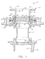
- Figure 1 is a cross sectional view of a transfer tube and associated connections in accordance with one embodiment of the present invention.
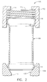
- Figure 2 is a cross section view of another transfer tube and associated connections in accordance with another embodiment of the present invention.
- FIG. 1 is a cross sectional view of a system 10 including a transfer tube 12 and associated transfer tube end assemblies 14 and 16 in accordance with one embodiment of the present invention.
- Transfer tube end assembly 14 includes a fitting 18 having a first interface end 20 having bolt openings 22 and a second interface end 24 having bolt openings 26.
- First interface end 20 may, for example, be bolted to a surface of a gas turbine engine.
- Second interface end 24 is bolted to a transfer tube fitting 28 having bolt openings 30 and a transfer tube opening 32 therethrough.
- a gasket 34 located in a gasket groove 36 in second interface end 24, forms a seal with transfer tube fitting 28.
- a bore 38 extends through fitting 18, and bore 38 has a first bore section 40, a second bore section 42, and a third bore section 44.
- Second bore section 42 has a diameter greater than the diameter of first bore section 40
- third bore section 44 has a diameter greater than the diameter of second bore section 42.
- a snap ring 46 is located in a groove 48 in a surface of third bore section 44, and snap ring 46 serves as a stop as described below in more detail.
- a transfer tube seat 50 is sized to be at least partially located within third bore section 44, and seat 50 includes a conical, or spherical, seat 52 on an inner diameter surface at a first end 54 and a stop arm 56 at a second end 58.
- a piston ring 60 is secured within a groove 62 which extends around an outer diameter surface of seat 50, and piston ring 60 cooperates with transfer tube fitting 28 to form a seal.
- Transfer tube seat 50 is spring loaded in that a spring 64 is positioned within bore 38 and exerts a force against seat 50 to push seat 50 into contact with transfer tube 12. Stop arm 56 cooperates with snap ring 48 to prevent separating seat 50 from fitting 18.
- Transfer tube end assembly 16 comprises a fitting 66 having a bore 67 extending therethrough and a spherical or conical seat 69 for mating with transfer tube 12.
- Transfer tube 12 which may be machined or formed of sheet metal, has spherical ends 68 and 70 for seating in transfer tube end assembly seats 50 and 69.
- Tube ends 68 and 70 may be coated to minimize differential motion induced wear.
- Spherical transfer tube ends 68 and 70 seat on precisely machined, conical/spherical seats 52 and 69, which permit angular motion of interfacing components without lift off and therefore assures minimal leakage.
- Axial seating force between transfer tube 12 and seats 50 and 69 is provided by spring 64 which assures contact over the breadth of operational inertial loadings.
- Conical/spherical seats 52 and 69 in combination with spring loading assures seating contact across all expected differential motions, i.e., axial, radial and rotation motion. All leak paths are closed and transfer tube contact is maintained against any expected wear or dimensional stack-up or dynamic unseating by the wear compensating, independently spring loaded external transfer tube removable end assembly 14.
- the above described system combines the advantages of the spherically ended transfer tube, appropriately coated or having selected materials which minimize wear, with independent axial spring loading of the opposing seats which assures continuous sealing contact regardless of dynamic loading, dimensional stack-up or geometry change resulting from interfaced wear. Vibratory loading induced wear is substantially eliminated through proper selection of the axial seating spring force.
- the spring load force should be selected to exceed the expected dynamic inertial unseating force.
- the spring loading of the seats provides axial rather than radial seating of the transfer tube.
- the spring also is independent of stack-up and wear and therefore provides constant axial force.
- Interfaces external to system 10 can be of any type, e.g., sliding or fixed.
- any material combination or sealing combination allowing transfer tube seating independent of its sealing functions and which assures dynamic seating independent of sealing functions at all conditions while permitting large relative motion between either sealing end of the transfer tube, could be utilized.
- Figure 2 is a cross section view of another system 100 including end assemblies 102 and 104 and a transfer tube 106.
- Each assembly 102 and 104 includes a bore 108 and 110.
- a spring 112 is positioned in bore 108 and is compressed between a ledge 114 and an end 116 of tube 106.
- End 118 of tube 106 is seated on a spherical or conical seat 120.
- End 118 is spherical or conical so that a seal is formed between end 118 and the walls of seat 120.
- End 116 is spherical and fits tight in bore 108 of end assembly 102. For minimal leakage between end 116 and bore 108, the diametral fit should be near zero, or zero.
- any diametral clearance between end 116 and bore 108 represents potential for wear, except that spring 112 exerts a force against tube 106 so that tube end 118 remains positioned on seat 120 and tube end 116 is therefore restrained against random dithering against bore 108.
- End 116 in bore 108 is limited to rotational excursions in magnitude less than that required to unseal end 116 from bore 108.
- Spring 112 exerts a force against tube 106 so that tube end 118 remains positioned on seat 118.
- System 100 is believed to be easier and more simple to implement than system 10.
- System 10 has no displacement and seals fully at all levels of motion.
- Both systems 10 and 100 are vibration proof in that the axial spring force always seats the tube.
Abstract
Description
- This invention relates generally to gas turbine engines and. more particularly, to transfer tubes utilized in connection with such engines.
- Transfer tubes often are utilized in aircraft engines to transmit engine air having one temperature and pressure from one chamber to another chamber physically removed from the one chamber. The transfer tube may span a third chamber having a different air temperature and pressure than the air temperature and pressure in the transfer tube, and the air in the transfer tube should be isolated from the air in the third chamber. Generally, the objective is to move the air from the first chamber into the second chamber without leaking the air into the third chamber.
- To achieve this objective, the transfer tube typically is placed into and maintained in intimate contact with interface seats at the first and second chamber. The interface contact, however, has to avoid wear from differential motion which could cause leakage and rattle induced vibratory distress. The interface requirements of minimal leakage and vibratory integrity are in conflict with the requirements of low interface wear and of allowing differential motion between the transfer tube ends.
- Satisfying the interface requirements often is achieved by off-optimizing each individual requirement. These compromises often result in less than desired transfer tube mission life and sealing performance. It would be desirable to provide a transfer tube connection which minimizes leakage and wear yet provides maximum differential motion and vibratory integrity.
- These and other objects may be attained by a system including transfer tube and end assemblies which provide independent axial spring loading of opposing seats to assure continuous sealing contact regardless of dynamic loading, dimensional stack-up or geometry change resulting from interfaced wear. More particularly, and in one embodiment, a first transfer tube end assembly includes a fitting having a first interface end and a second interface end. First interface end may, for example, be bolted to a surface of a gas turbine engine. Second interface end is bolted to a transfer tube fitting. A bore extends through the fitting, and a transfer tube seat is sized to be at least partially located within the bore. The transfer tube seat is spring loaded in that a spring is positioned within the bore and exerts a force against the seat to push the seat into contact with the transfer tube.
- The second transfer tube end assembly also includes a spherical or conical seat for mating with the transfer tube. Particularly, the transfer tube has spherical ends for seating in the transfer tube end assembly seats. The conical/spherical seats permit angular motion of interfacing components without lift off and therefore assure minimal leakage. In addition, the axial seating force between the transfer tube and the seats is provided by the spring which assures contact over the breadth of operational inertial loadings. The conical/spherical seats in combination with the spring loading assure seating contact across all expected differential motions, i.e., axial, radial and rotation motion. All leak paths are closed and transfer tube contact is maintained against any expected wear or dimensional stack-up or dynamic unseating.
- Embodiments of the invention will now be described, by way of example, with reference to the accompanying drawings, in which:
- Figure 1 is a cross sectional view of a transfer tube and associated connections in accordance with one embodiment of the present invention.
- Figure 2 is a cross section view of another transfer tube and associated connections in accordance with another embodiment of the present invention.
- Figure 1 is a cross sectional view of a
system 10 including atransfer tube 12 and associated transfertube end assemblies tube end assembly 14 includes afitting 18 having afirst interface end 20 havingbolt openings 22 and asecond interface end 24 havingbolt openings 26.First interface end 20 may, for example, be bolted to a surface of a gas turbine engine.Second interface end 24 is bolted to atransfer tube fitting 28 havingbolt openings 30 and a transfer tube opening 32 therethrough. A gasket 34, located in a gasket groove 36 insecond interface end 24, forms a seal withtransfer tube fitting 28. - A
bore 38 extends through fitting 18, andbore 38 has afirst bore section 40, asecond bore section 42, and athird bore section 44.Second bore section 42 has a diameter greater than the diameter offirst bore section 40, andthird bore section 44 has a diameter greater than the diameter ofsecond bore section 42. Asnap ring 46 is located in agroove 48 in a surface ofthird bore section 44, andsnap ring 46 serves as a stop as described below in more detail. - A
transfer tube seat 50 is sized to be at least partially located withinthird bore section 44, andseat 50 includes a conical, or spherical,seat 52 on an inner diameter surface at afirst end 54 and astop arm 56 at asecond end 58. Apiston ring 60 is secured within agroove 62 which extends around an outer diameter surface ofseat 50, andpiston ring 60 cooperates with transfer tube fitting 28 to form a seal.Transfer tube seat 50 is spring loaded in that aspring 64 is positioned withinbore 38 and exerts a force againstseat 50 to pushseat 50 into contact withtransfer tube 12. Stoparm 56 cooperates withsnap ring 48 to prevent separatingseat 50 from fitting 18. - Transfer
tube end assembly 16 comprises afitting 66 having abore 67 extending therethrough and a spherical orconical seat 69 for mating withtransfer tube 12.Transfer tube 12, which may be machined or formed of sheet metal, hasspherical ends end assembly seats transfer tube ends spherical seats transfer tube 12 andseats spring 64 which assures contact over the breadth of operational inertial loadings. Conical/spherical seats removable end assembly 14. - The above described system combines the advantages of the spherically ended transfer tube, appropriately coated or having selected materials which minimize wear, with independent axial spring loading of the opposing seats which assures continuous sealing contact regardless of dynamic loading, dimensional stack-up or geometry change resulting from interfaced wear. Vibratory loading induced wear is substantially eliminated through proper selection of the axial seating spring force. The spring load force should be selected to exceed the expected dynamic inertial unseating force. The spring loading of the seats provides axial rather than radial seating of the transfer tube. The spring also is independent of stack-up and wear and therefore provides constant axial force.
- Interfaces external to
system 10 can be of any type, e.g., sliding or fixed. In addition, any material combination or sealing combination allowing transfer tube seating independent of its sealing functions and which assures dynamic seating independent of sealing functions at all conditions while permitting large relative motion between either sealing end of the transfer tube, could be utilized. - For example, Figure 2 is a cross section view of another
system 100 includingend assemblies transfer tube 106. Eachassembly bore spring 112 is positioned inbore 108 and is compressed between aledge 114 and anend 116 oftube 106.End 118 oftube 106 is seated on a spherical orconical seat 120.End 118 is spherical or conical so that a seal is formed betweenend 118 and the walls ofseat 120.End 116 is spherical and fits tight inbore 108 ofend assembly 102. For minimal leakage betweenend 116 and bore 108, the diametral fit should be near zero, or zero. Any diametral clearance betweenend 116 andbore 108 represents potential for wear, except thatspring 112 exerts a force againsttube 106 so thattube end 118 remains positioned onseat 120 andtube end 116 is therefore restrained against random dithering againstbore 108.End 116 inbore 108 is limited to rotational excursions in magnitude less than that required tounseal end 116 frombore 108.Spring 112 exerts a force againsttube 106 so thattube end 118 remains positioned onseat 118. Many of the same advantages provided bysystem 10 also are provided bysystem 100. -
System 100 is believed to be easier and more simple to implement thansystem 10.System 10, however, has no displacement and seals fully at all levels of motion. Bothsystems
Claims (11)
- A transfer tube system, comprising:a transfer tube;a first transfer tube end assembly comprising a fitting having a bore extending therethrough, one end of said transfer tube positioned in said first assembly bore, and a spring located in said bore and exerting a force against said transfer tube; anda second transfer tube end assembly comprising a seat, one end of said transfer tube located in said second assembly seat.
- A transfer tube system in accordance with Claim 1 wherein said ends of said transfer tube have a spherical shape and form seals with surfaces of said first assembly bore and said second assembly seat.
- A transfer tube system in accordance with Claim 2 wherein said spring is in direct contact with said transfer tube.
- A transfer tube system in accordance with Claim 1 wherein said first transfer tube end assembly further comprises a seat, said seat comprising a seating surface and said one end of said transfer tube seated on said seating surface, said spring in direct contact with said seat.
- A transfer tube system in accordance with Claim 1 further comprising a transfer tube fitting, said transfer tube fitting secured to said first assembly fitting, said transfer tube fitting having an opening therethrough, said transfer tube extending through said transfer tube fitting opening.
- A transfer tube system, comprising:transfer tube;first transfer tube end assembly comprising a fitting having a bore extending therethrough, a seat comprising a seating surface, one end of said transfer tube positioned in said first assembly bore and seated on said seating surface, and a spring located in said bore and exerting a force against said seat to maintain said transfer tube seated on said seating surface;a transfer tube fitting secured to said first assembly fitting, said transfer tube fitting having an opening therethrough, said transfer tube extending through said transfer tube fitting opening; anda second transfer tube end assembly comprising a seat, one end of said transfer tube located in said second assembly seat.
- A transfer tube system in accordance with Claim 4 or claim 6 wherein said seat further comprises a stop arm for preventing said seat from separating from said first end assembly fitting.
- A transfer tube system in accordance with Claim 4 or claim 6 wherein said first assembly seat is spherical.
- A transfer tube system in accordance with Claim 4 or claim 6 wherein said first assembly seat is conical.
- A transfer tube system in accordance with any one of Claims 1 to 9 wherein said first end assembly fitting further comprises a first interface end and a second interface end, said first interface end comprising a plurality of bolt openings.
- A transfer tube system in accordance with any one of Claims 1 to 10 wherein said first end assembly fitting comprises a bore having a first bore section, a second bore section, and a third bore section, said second bore section having a diameter greater than a diameter of said first bore section, and said third bore section having a diameter greater than said second bore section diameter.
Applications Claiming Priority (2)
| Application Number | Priority Date | Filing Date | Title |
|---|---|---|---|
| US08/982,003 US5964250A (en) | 1997-12-01 | 1997-12-01 | Low leakage, articulating fluid transfer tube |
| US982003 | 1997-12-01 |
Publications (3)
| Publication Number | Publication Date |
|---|---|
| EP0919774A2 true EP0919774A2 (en) | 1999-06-02 |
| EP0919774A3 EP0919774A3 (en) | 2000-11-22 |
| EP0919774B1 EP0919774B1 (en) | 2005-05-04 |
Family
ID=25528783
Family Applications (1)
| Application Number | Title | Priority Date | Filing Date |
|---|---|---|---|
| EP98309752A Expired - Lifetime EP0919774B1 (en) | 1997-12-01 | 1998-11-27 | Flame tube interconnector |
Country Status (4)
| Country | Link |
|---|---|
| US (1) | US5964250A (en) |
| EP (1) | EP0919774B1 (en) |
| JP (1) | JPH11229816A (en) |
| DE (1) | DE69830037T2 (en) |
Cited By (4)
| Publication number | Priority date | Publication date | Assignee | Title |
|---|---|---|---|---|
| WO2001092787A1 (en) * | 2000-06-02 | 2001-12-06 | Nuovo Pignone Holding S.P.A. | Flame-passage device for non-annular gas turbine combustion chambers |
| FR2883599A1 (en) * | 2005-03-23 | 2006-09-29 | Snecma Moteurs Sa | CONNECTION DEVICE BETWEEN A COOLING AIR PASSING ENCLOSURE AND A DISTRIBUTOR'S TANK IN A TURBOMACHINE |
| DE102011110837A1 (en) * | 2011-08-23 | 2013-02-28 | IFUTEC Ingenieurbüro für Umformtechnik GmbH | Housing for fluid conduit, has functional element that is fixed between tubular elements so that tubular elements are connected to adjacent tubular elements |
| RU194926U1 (en) * | 2019-10-15 | 2019-12-30 | Публичное Акционерное Общество "Одк-Сатурн" | FLAME CONVERTER ASSEMBLY ASSEMBLY WITH HEAT PIPE COMBUSTION CHAMBER OF A GAS TURBINE ENGINE |
Families Citing this family (11)
| Publication number | Priority date | Publication date | Assignee | Title |
|---|---|---|---|---|
| EP1079068A3 (en) * | 1999-08-27 | 2004-01-07 | General Electric Company | Connector tube for a turbine rotor cooling circuit |
| US6655659B2 (en) * | 2002-02-08 | 2003-12-02 | Fisher Controls International Inc. | One-piece sanitary seat ring |
| ITMI20020910A1 (en) * | 2002-04-29 | 2003-10-29 | Nuovo Pignone Spa | SEALING DEVICE FOR COUPLING A PIPE WITH A HOLE |
| US8864445B2 (en) * | 2012-01-09 | 2014-10-21 | General Electric Company | Turbine nozzle assembly methods |
| US20130333389A1 (en) * | 2012-06-15 | 2013-12-19 | General Electric Company | Cross fire tube retention system for a gas turbine engine |
| US20140137536A1 (en) * | 2012-11-21 | 2014-05-22 | General Electric Company | Super telescoping cross-fire tube and method of assembling a combustor structure |
| US9353952B2 (en) * | 2012-11-29 | 2016-05-31 | General Electric Company | Crossfire tube assembly with tube bias between adjacent combustors |
| US10161635B2 (en) * | 2014-06-13 | 2018-12-25 | Rolls-Royce Corporation | Combustor with spring-loaded crossover tubes |
| JP6325930B2 (en) * | 2014-07-24 | 2018-05-16 | 三菱日立パワーシステムズ株式会社 | Gas turbine combustor |
| US10156363B2 (en) * | 2016-07-20 | 2018-12-18 | General Electric Company | Compact multi-piece spring-loaded crossfire tube |
| KR102498871B1 (en) * | 2021-01-14 | 2023-02-10 | 한화에어로스페이스 주식회사 | Turbine oil supply apparatus |
Family Cites Families (22)
| Publication number | Priority date | Publication date | Assignee | Title |
|---|---|---|---|---|
| DE337119C (en) * | 1921-05-26 | Friedrich Wilhelm Koehler | Pipe coupling with hemispherical end flanges | |
| US1604868A (en) * | 1926-10-26 | Ball joint | ||
| GB256746A (en) * | 1925-06-17 | 1926-08-19 | John Shaw And Sons Salford Ltd | Improvements in swivel pipe joints |
| US1780693A (en) * | 1926-03-25 | 1930-11-04 | Jacob B Yazel | Exhaust connection |
| GB308680A (en) * | 1928-03-26 | 1930-05-01 | Daimler Benz Ag | Improvements in and connected with vacuum brakes for motor vehicles |
| US1872666A (en) * | 1931-02-13 | 1932-08-23 | Diamond Metal Products Company | Swivel coupling |
| US2876876A (en) * | 1955-11-25 | 1959-03-10 | Clessie L Cummins | Diesel engine braking control |
| US2832195A (en) * | 1956-04-16 | 1958-04-29 | Gen Electric | Cross-ignition tube assembly for gas turbine combustion system |
| FR1231337A (en) * | 1958-07-31 | 1960-09-28 | Kloeckner Humboldt Deutz Ag | Four-stroke internal combustion engine |
| US3130747A (en) * | 1961-05-15 | 1964-04-28 | Sterer Engineering And Mfg Com | Flow regulator |
| US3173710A (en) * | 1962-05-02 | 1965-03-16 | Western Piping & Engineering C | Exhaust system for vehicles |
| US3162940A (en) * | 1963-07-10 | 1964-12-29 | Rotherm Engineering Company In | Methods of making conduit expansion joints |
| US3449937A (en) * | 1967-06-23 | 1969-06-17 | Columbia Summerill Corp | High pressure fuel line heads and the like |
| SE336642B (en) * | 1969-10-28 | 1971-07-12 | Astra Meditec Ab | |
| US3836083A (en) * | 1973-10-11 | 1974-09-17 | Stanadyne Inc | Shower head with flow control washer |
| JPS60244659A (en) * | 1984-05-18 | 1985-12-04 | Tokico Ltd | Car braking device |
| JP2789197B2 (en) * | 1988-08-19 | 1998-08-20 | 臼井国際産業株式会社 | High-pressure metal pipe having a connection head and a method of forming the head |
| DE3906529A1 (en) * | 1988-11-03 | 1990-09-06 | Teves Gmbh Alfred | SLIP-CONTROLLED BRAKE SYSTEM |
| US5361577A (en) * | 1991-07-15 | 1994-11-08 | General Electric Company | Spring loaded cross-fire tube |
| US5396918A (en) * | 1993-11-18 | 1995-03-14 | Agricultural Products, Inc. | Water pressure regulator and method for regulating pressure through a valve |
| US5603531A (en) * | 1994-12-06 | 1997-02-18 | United Technologies Corporation | Blind assembly-swivel crossover tube |
| US5577775A (en) * | 1995-02-07 | 1996-11-26 | Barco, A Division Of Marison Industries | Bearingless coolant union |
-
1997
- 1997-12-01 US US08/982,003 patent/US5964250A/en not_active Expired - Lifetime
-
1998
- 1998-11-27 EP EP98309752A patent/EP0919774B1/en not_active Expired - Lifetime
- 1998-11-27 DE DE69830037T patent/DE69830037T2/en not_active Expired - Lifetime
- 1998-11-30 JP JP10338341A patent/JPH11229816A/en active Pending
Non-Patent Citations (1)
| Title |
|---|
| None |
Cited By (8)
| Publication number | Priority date | Publication date | Assignee | Title |
|---|---|---|---|---|
| WO2001092787A1 (en) * | 2000-06-02 | 2001-12-06 | Nuovo Pignone Holding S.P.A. | Flame-passage device for non-annular gas turbine combustion chambers |
| US6834491B2 (en) | 2000-06-02 | 2004-12-28 | Nuovo Pignone Holding S.P.A. | Flame-passage device for non-annular gas turbine combustion chambers |
| FR2883599A1 (en) * | 2005-03-23 | 2006-09-29 | Snecma Moteurs Sa | CONNECTION DEVICE BETWEEN A COOLING AIR PASSING ENCLOSURE AND A DISTRIBUTOR'S TANK IN A TURBOMACHINE |
| US7540707B2 (en) | 2005-03-23 | 2009-06-02 | Snecma | Link device between an enclosure for passing cooling air and a stator nozzle in a turbomachine |
| US7625175B2 (en) | 2005-03-23 | 2009-12-01 | Snecma | Link device between an enclosure for passing cooling air and a stator nozzle in a turbomachine |
| EP1705340A3 (en) * | 2005-03-23 | 2012-05-16 | Snecma | Connector between a cooling air plenum and a stator vane in a turbomachine |
| DE102011110837A1 (en) * | 2011-08-23 | 2013-02-28 | IFUTEC Ingenieurbüro für Umformtechnik GmbH | Housing for fluid conduit, has functional element that is fixed between tubular elements so that tubular elements are connected to adjacent tubular elements |
| RU194926U1 (en) * | 2019-10-15 | 2019-12-30 | Публичное Акционерное Общество "Одк-Сатурн" | FLAME CONVERTER ASSEMBLY ASSEMBLY WITH HEAT PIPE COMBUSTION CHAMBER OF A GAS TURBINE ENGINE |
Also Published As
| Publication number | Publication date |
|---|---|
| JPH11229816A (en) | 1999-08-24 |
| DE69830037D1 (en) | 2005-06-09 |
| DE69830037T2 (en) | 2006-01-19 |
| EP0919774B1 (en) | 2005-05-04 |
| EP0919774A3 (en) | 2000-11-22 |
| US5964250A (en) | 1999-10-12 |
Similar Documents
| Publication | Publication Date | Title |
|---|---|---|
| EP0919774B1 (en) | Flame tube interconnector | |
| US5014999A (en) | Pressure enhanced self aligning seal | |
| US5026252A (en) | Sealing device for turbo engines and the like | |
| CA2552667C (en) | Tandem dual element intershaft carbon seal | |
| US5071140A (en) | Self-pressurized gasket seal | |
| US7380768B2 (en) | Balanced-plug cage style control valve and bonnet seal assembly | |
| CA2257833C (en) | Pipe joint and seal therefor | |
| US6019515A (en) | Externally pressurized gas bearing assembly | |
| EP2002160B1 (en) | Mechanical seal with thermally stable mating ring | |
| US5442993A (en) | Self-aligning piston | |
| US20040017045A1 (en) | Fluid seal | |
| EP1126186A2 (en) | Modular, compliant sealing bearing assembly | |
| GB2103295A (en) | Inspection hole plug for gas turbine engine | |
| US5901965A (en) | Bellows seal having balanced, de-coupled seal ring and seal ring shell | |
| US4427220A (en) | Flexible joint for conduit | |
| JP3059093B2 (en) | Butterfly valve for high temperature fluid | |
| US5697651A (en) | Flexible duct joint having a low leakage, pressure-balanced bellows seal | |
| US4260131A (en) | Low and high operating temperatures valve | |
| US6039322A (en) | Sealing arrangement | |
| GB2050572A (en) | Fire safety seal in or for a fluid flow control valve | |
| US5192083A (en) | Single ring sector seal | |
| US6196179B1 (en) | Internal combustion engine | |
| GB2366842A (en) | A bearing chamber sealing system | |
| US11396947B2 (en) | Face seal with welded bellows | |
| CN113383150B (en) | Valve body for a valve and valve |
Legal Events
| Date | Code | Title | Description |
|---|---|---|---|
| PUAI | Public reference made under article 153(3) epc to a published international application that has entered the european phase |
Free format text: ORIGINAL CODE: 0009012 |
|
| AK | Designated contracting states |
Kind code of ref document: A2 Designated state(s): DE FR GB |
|
| AX | Request for extension of the european patent |
Free format text: AL;LT;LV;MK;RO;SI |
|
| PUAL | Search report despatched |
Free format text: ORIGINAL CODE: 0009013 |
|
| AK | Designated contracting states |
Kind code of ref document: A3 Designated state(s): AT BE CH CY DE DK ES FI FR GB GR IE IT LI LU MC NL PT SE |
|
| AX | Request for extension of the european patent |
Free format text: AL;LT;LV;MK;RO;SI |
|
| RIC1 | Information provided on ipc code assigned before grant |
Free format text: 7F 23R 3/48 A, 7F 16L 27/02 B |
|
| 17P | Request for examination filed |
Effective date: 20010522 |
|
| AKX | Designation fees paid |
Free format text: DE FR GB |
|
| 17Q | First examination report despatched |
Effective date: 20040311 |
|
| GRAP | Despatch of communication of intention to grant a patent |
Free format text: ORIGINAL CODE: EPIDOSNIGR1 |
|
| RIN1 | Information on inventor provided before grant (corrected) |
Inventor name: MUELLER, PETER WALTER |
|
| GRAS | Grant fee paid |
Free format text: ORIGINAL CODE: EPIDOSNIGR3 |
|
| GRAA | (expected) grant |
Free format text: ORIGINAL CODE: 0009210 |
|
| AK | Designated contracting states |
Kind code of ref document: B1 Designated state(s): DE FR GB |
|
| REG | Reference to a national code |
Ref country code: GB Ref legal event code: FG4D |
|
| REF | Corresponds to: |
Ref document number: 69830037 Country of ref document: DE Date of ref document: 20050609 Kind code of ref document: P |
|
| PLBE | No opposition filed within time limit |
Free format text: ORIGINAL CODE: 0009261 |
|
| STAA | Information on the status of an ep patent application or granted ep patent |
Free format text: STATUS: NO OPPOSITION FILED WITHIN TIME LIMIT |
|
| ET | Fr: translation filed | ||
| 26N | No opposition filed |
Effective date: 20060207 |
|
| REG | Reference to a national code |
Ref country code: FR Ref legal event code: PLFP Year of fee payment: 18 |
|
| PGFP | Annual fee paid to national office [announced via postgrant information from national office to epo] |
Ref country code: DE Payment date: 20151127 Year of fee payment: 18 Ref country code: GB Payment date: 20151127 Year of fee payment: 18 |
|
| PGFP | Annual fee paid to national office [announced via postgrant information from national office to epo] |
Ref country code: FR Payment date: 20151117 Year of fee payment: 18 |
|
| REG | Reference to a national code |
Ref country code: DE Ref legal event code: R119 Ref document number: 69830037 Country of ref document: DE |
|
| GBPC | Gb: european patent ceased through non-payment of renewal fee |
Effective date: 20161127 |
|
| REG | Reference to a national code |
Ref country code: FR Ref legal event code: ST Effective date: 20170731 |
|
| PG25 | Lapsed in a contracting state [announced via postgrant information from national office to epo] |
Ref country code: FR Free format text: LAPSE BECAUSE OF NON-PAYMENT OF DUE FEES Effective date: 20161130 |
|
| PG25 | Lapsed in a contracting state [announced via postgrant information from national office to epo] |
Ref country code: GB Free format text: LAPSE BECAUSE OF NON-PAYMENT OF DUE FEES Effective date: 20161127 Ref country code: DE Free format text: LAPSE BECAUSE OF NON-PAYMENT OF DUE FEES Effective date: 20170601 |