EP0921006B1 - Printer assembly - Google Patents
Printer assembly Download PDFInfo
- Publication number
- EP0921006B1 EP0921006B1 EP98309422A EP98309422A EP0921006B1 EP 0921006 B1 EP0921006 B1 EP 0921006B1 EP 98309422 A EP98309422 A EP 98309422A EP 98309422 A EP98309422 A EP 98309422A EP 0921006 B1 EP0921006 B1 EP 0921006B1
- Authority
- EP
- European Patent Office
- Prior art keywords
- carriage
- printer
- printing
- media
- Prior art date
- Legal status (The legal status is an assumption and is not a legal conclusion. Google has not performed a legal analysis and makes no representation as to the accuracy of the status listed.)
- Expired - Lifetime
Links
Images

Classifications
-
- B—PERFORMING OPERATIONS; TRANSPORTING
- B41—PRINTING; LINING MACHINES; TYPEWRITERS; STAMPS
- B41J—TYPEWRITERS; SELECTIVE PRINTING MECHANISMS, i.e. MECHANISMS PRINTING OTHERWISE THAN FROM A FORME; CORRECTION OF TYPOGRAPHICAL ERRORS
- B41J2/00—Typewriters or selective printing mechanisms characterised by the printing or marking process for which they are designed
- B41J2/005—Typewriters or selective printing mechanisms characterised by the printing or marking process for which they are designed characterised by bringing liquid or particles selectively into contact with a printing material
- B41J2/01—Ink jet
- B41J2/21—Ink jet for multi-colour printing
- B41J2/2132—Print quality control characterised by dot disposition, e.g. for reducing white stripes or banding
Definitions
- the disclosed invention relates to a printer including a vibration inducing element.
- An ink jet printer forms a printed image by printing a pattern of individual dots at particular locations of an array defined for the printing medium.
- the locations are conveniently visualized as being small dots in a rectilinear array.
- the locations are sometimes called “dot locations,” “dot positions,” or “pixels”.
- the printing operation can be viewed as the filling of a pattern of dot locations with dots of ink.
- Ink jet printers print dots by ejecting very small drops of ink onto the print medium, and typically include a movable print carriage that supports one or more printheads each having ink ejecting nozzles.
- the print carriage traverses back and forth over the surface of the print medium, and the nozzles are controlled to eject drops of ink at appropriate times pursuant to command of a microcomputer or other controller, wherein the timing of the application of the ink drops is intended to correspond to the pattern of pixels of the image being printed.
- a plurality of rows of pixels are printed in each traverse or scan of the print carriage.
- the particular ink ejection mechanism within the printhead may take on a variety of different forms known to those skilled in the art, such as those using thermal printhead or piezoelectric technology.
- thermal printhead or piezoelectric technology two earlier thermal ink jet ejection mechanisms are shown in commonly assigned U.S. Patent Nos. 5,278,584 and 4,683,481.
- an ink barrier layer containing ink channels and ink vaporization chambers is disposed between a nozzle orifice plate and a thin film substrate.
- the thin film substrate typically includes arrays of heater elements such as thin film resistors which are selectively energized to heat ink within the vaporization chambers. Upon heating, an ink droplet is ejected from a nozzle associated with the energized heater element.
- By selectively energizing heater elements as the printhead moves across the print medium ink drops are ejected onto the print medium in a pattern to form the desired image.
- JP 58 107 356 discloses a printing system with a carriage supporting a laminated head.
- a prezoelectric vibrator is provided between the carriage and the head for inducing vibration to the head.
- a gradient of a sinusoidal wave voltage is applied to the vibrator.
- the present invention seeks to provide improved printing.
- the preferred embodiment can provide an ink jet printer having reduced print banding caused by poor paper advance or misdirected nozzles and print banding reduction that does not substantially reduce throughput.
- the preferred embodiment provides a printer which includes a movable print carriage for reciprocatingly scanning along a carriage scan axis, a removable printhead having a plurality of printing elements and supported by the movable print carriage, a print media moving mechanism for moving print media along a media axis through a print zone, and a vibration inducing element for causing relative vibration between the carriage and the print media such that locations along the media axis of dots printed by the printing elements are minutely randomly varied.
- the vibration inducing element includes a piezoelectric element.
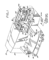
- FIG. 1 is a partially fragmented schematic perspective view of an ink jet printing mechanism that employs random noise vibration.
- FIG. 2 is a side elevational view of the print carriage of the printing mechanism of FIG. 1.
- FIG. 3 is a bottom plan view of the print carriage of the printing mechanism of FIG. 1 showing the printheads of the print cartridges disposed in the print carriage.
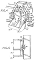
- FIG. 4 is a schematic perspective view of the print carriage of the printing mechanism of FIG. 1.
- FIG. 5 is a top plan view of the print carriage of the printing mechanism of FIG. 1.
- FIG. 1 set forth therein is a schematic partially fragmented perspective view depicting, by way of illustrative example, major mechanical components of a swath type ink jet printer 20 employing random noise vibration.
- the printer includes a chassis 22 surrounded by a housing or enclosure 24, typically of a molded plastic material.
- the chassis 22 is formed for example of sheet metal and includes a vertical panel 22a.
- An example of a printer is the Hewlett-Packard Company's DeskJet 722 brand ink jet printer.
- Sheets of print media are individually fed through a print zone 25 by an adaptive print media handling system 26 that includes a feed tray 28 for storing print media before printing.
- the print media may be any type of suitable printable sheet material such as paper, card-stock, transparencies, mylar, and the like, but for convenience the illustrated embodiments described as using paper as the print medium.
- a series of conventional motor-driven rollers including a drive roller 29 driven by a stepper motor may be used to move print media from the feed tray 28 into the print zone 25, as shown in FIG. 2 for sheet 37, for printing. After printing, the drive roller 29 drives the printed sheet onto a pair of retractable output drying wing members 30 which are shown extended to receive a printed sheet.
- the wing members 30 hold the newly printed sheet for a short time above any previously printed sheets still drying in an output tray 32 before pivotally retracting to the sides, as shown by curved arrows 33, to drop the newly printed sheet into the output tray 32.
- the print media handling system may include a series of adjustment mechanisms for accommodating different sizes of print media, including letter, legal, A-4, envelopes, etc., such as a sliding length adjustment arm 34 and an envelope feed slot 35.
- the printer of FIG. 1 further includes a printer controller 36, schematically illustrated as a microprocessor, disposed on a printed circuit board 39 supported on the rear side of the chassis vertical panel 22a.
- the printer controller 36 receives instructions from a host device such as a personal computer (not shown) and controls the operation of the printer including advance of print media through the print zone 25 and the ink jet printing of dots, discussed further herein.
- a print carriage slider rod 38 having a longitudinal axis parallel to a carriage scan axis is supported by the chassis 22 to slideably support a print carriage 40 for reciprocating translational movement or scanning along the carriage scan axis.
- the print carriage 40 more particularly includes a body portion 75 having a rear wall 185, a front apron 186, and L-shaped side walls 174, 176 that extend forwardly from lateral edges of the rear wall 185 to lateral edges of the front apron 186.
- An alignment wall or web 76 divides an interior portion of the carriage body into first and second chambers 80, 82 which respectively house first and second removable ink jet printhead cartridges 50, 52 (each of which is sometimes called a "pen,” “print cartridge,” or “cartridge”).
- the print cartridges 50, 52 include respective printheads 54, 56 that respectively have generally downwardly facing nozzles for ejecting ink generally downwardly onto a portion of the print media 37 that is in the print zone 25.
- a latch mechanism that includes clamping levers, latch members or lids 70, 72 pivotally attached by a hinge 74 to the body portion 75 of the print carriage 51 cooperatively acts with the print carriage body 75 and the print cartridges 50, 52 to clamp the cartridges 50, 52 in the chambers 80, 82.
- the print media 37 is advanced through the print zone 25 along a media axis which is parallel to the tangent to the portion of the print media 37 that is beneath and traversed by the nozzles of the cartridges 50, 52. If the media axis and the carriage axis are located on the same plane, as shown in FIG. 1, they would be perpendicular to each other.
- the print carriage 40 further includes a pair of bearings 55 which slidably support the print carriage 40 as it slides along the slider rod 38.
- a vertical anti-rotation guide arm 81 is attached to the back of the rear wall 185 of the print carriage body 75 and includes a slide bushing 83 that engages a horizontally disposed anti-pivot bar 85 that is formed integrally with the vertical panel 22a of the chassis 22, for example.
- the bearings 55 and the slide bushing 83 provide a three-point carriage support system; and the vertical anti-rotation guide arm 81, the slide bushing 83 and the horizontal anti-pivot bar 85 cooperate to prevent forward pivoting of the print carriage 40 about the slider rod 38.
- the print cartridge 50 is a monochrome printing cartridge while the print cartridge 52 is a tri-color printing cartridge.
- discrete monochrome cartridges may be used.
- the print carriage 40 is driven along the slider rod 38 by an endless belt 58 which can be driven in a conventional manner, and a linear encoder strip 59 is utilized to detect position of the print carriage 40 along the carriage scan axis, for example in accordance with conventional techniques.
- a vibration inducing element which in this example vibrates at a frequency in the range of about 100 Hz to about 1000 Hz, is provided to induce a vibration of very small amplitude along the media axis between the printheads and the print media as the carriage traverses the print media.
- the vibration inducing element comprises a piezoelectric element 61 disposed between the vertical guide arm 81 and the rear wall 185 of the carriage body 75. A voltage is applied to the piezoelectric element 61 which causes the carriage 40 to rotationally vibrate about the slider rod 38.
- the aim or direction of the nozzles of the printheads 54, 56 is vibrationally angularly varied over a small angle in a plane that is orthogonal to the media carriage axis.
- the vibrational angular variation the potential placement of dots along the media axis is vibratingly varied over a small interval, whereby the actual placement of dots along the media axis is vibratingly varied over such small interval.
- the print carriage 40 and the piezoelectric element are configured to provide a dot placement variation of about 6.4 ⁇ m (about .25 of 1/1000th of an inch).
- this embodiment introducing a small amount of mechanical noise into the placement of dots along the media axis, which reduces visible banding that would otherwise be caused by less than optimal paper advance or nozzle aim since the small amount of mechanical noise vibrates the placement of the dots that would otherwise define the bands.
- the sharpness of the printed image may be slightly degraded in exchange for reduced banding, and vibration inducing element may be selectively enabled and disabled.
- a piezoelectric element is disclosed as the vibrational noise introducing element
- other apparatus such as a small electric eccentric motor (frequently used in pagers as a silent vibrator) can be used.
- a small eccentric motor 161 schematically depicted in broken lines, can be conveniently attached to the wall 174 of the carriage body 40. Operation of the motor 161, which includes an eccentric load or mass 161a, causes micro-rotation of the carriage 40 about the slider rod 38 which in turn causes micro-displacement the placement of the printed dots.
Description
- The disclosed invention relates to a printer including a vibration inducing element.
- An ink jet printer forms a printed image by printing a pattern of individual dots at particular locations of an array defined for the printing medium. The locations are conveniently visualized as being small dots in a rectilinear array. The locations are sometimes called "dot locations," "dot positions," or "pixels". Thus, the printing operation can be viewed as the filling of a pattern of dot locations with dots of ink.
- Ink jet printers print dots by ejecting very small drops of ink onto the print medium, and typically include a movable print carriage that supports one or more printheads each having ink ejecting nozzles. The print carriage traverses back and forth over the surface of the print medium, and the nozzles are controlled to eject drops of ink at appropriate times pursuant to command of a microcomputer or other controller, wherein the timing of the application of the ink drops is intended to correspond to the pattern of pixels of the image being printed. Typically, a plurality of rows of pixels are printed in each traverse or scan of the print carriage. The particular ink ejection mechanism within the printhead may take on a variety of different forms known to those skilled in the art, such as those using thermal printhead or piezoelectric technology. For instance, two earlier thermal ink jet ejection mechanisms are shown in commonly assigned U.S. Patent Nos. 5,278,584 and 4,683,481. In a thermal system, an ink barrier layer containing ink channels and ink vaporization chambers is disposed between a nozzle orifice plate and a thin film substrate. The thin film substrate typically includes arrays of heater elements such as thin film resistors which are selectively energized to heat ink within the vaporization chambers. Upon heating, an ink droplet is ejected from a nozzle associated with the energized heater element. By selectively energizing heater elements as the printhead moves across the print medium, ink drops are ejected onto the print medium in a pattern to form the desired image.
- A consideration scanning carriage ink jet printers is the visible banding caused by poor paper advance or misdirected ink nozzles. Such banding has been addressed by software randomization. However, software randomization has been found to require multiple passes, wherein the number of passes increases with the inaccuracy of the paper advance. This significantly reduces throughput.
- JP 58 107 356 discloses a printing system with a carriage supporting a laminated head. A prezoelectric vibrator is provided between the carriage and the head for inducing vibration to the head.
- A gradient of a sinusoidal wave voltage is applied to the vibrator.
- The present invention seeks to provide improved printing.
- According to an aspect of the present invention, there is provided a printer as specified in claim 1.
- The preferred embodiment can provide an ink jet printer having reduced print banding caused by poor paper advance or misdirected nozzles and print banding reduction that does not substantially reduce throughput.
- The preferred embodiment provides a printer which includes a movable print carriage for reciprocatingly scanning along a carriage scan axis, a removable printhead having a plurality of printing elements and supported by the movable print carriage, a print media moving mechanism for moving print media along a media axis through a print zone, and a vibration inducing element for causing relative vibration between the carriage and the print media such that locations along the media axis of dots printed by the printing elements are minutely randomly varied. In accordance with a specific implementation, the vibration inducing element includes a piezoelectric element.
- An embodiment of the present invention is described below, by way of example only, with reference to the accompanying drawings, in which:
- FIG. 1 is a partially fragmented schematic perspective view of an ink jet printing mechanism that employs random noise vibration.
- FIG. 2 is a side elevational view of the print carriage of the printing mechanism of FIG. 1.
- FIG. 3 is a bottom plan view of the print carriage of the printing mechanism of FIG. 1 showing the printheads of the print cartridges disposed in the print carriage.
- FIG. 4 is a schematic perspective view of the print carriage of the printing mechanism of FIG. 1.
- FIG. 5 is a top plan view of the print carriage of the printing mechanism of FIG. 1.
- Referring now to FIG. 1, set forth therein is a schematic partially fragmented perspective view depicting, by way of illustrative example, major mechanical components of a swath type
ink jet printer 20 employing random noise vibration. The printer includes a chassis 22 surrounded by a housing orenclosure 24, typically of a molded plastic material. The chassis 22 is formed for example of sheet metal and includes avertical panel 22a. An example of a printer is the Hewlett-Packard Company's DeskJet 722 brand ink jet printer. - Sheets of print media are individually fed through a print zone 25 by an adaptive print
media handling system 26 that includes afeed tray 28 for storing print media before printing. The print media may be any type of suitable printable sheet material such as paper, card-stock, transparencies, mylar, and the like, but for convenience the illustrated embodiments described as using paper as the print medium. A series of conventional motor-driven rollers including adrive roller 29 driven by a stepper motor may be used to move print media from thefeed tray 28 into the print zone 25, as shown in FIG. 2 forsheet 37, for printing. After printing, thedrive roller 29 drives the printed sheet onto a pair of retractable output dryingwing members 30 which are shown extended to receive a printed sheet. Thewing members 30 hold the newly printed sheet for a short time above any previously printed sheets still drying in an output tray 32 before pivotally retracting to the sides, as shown bycurved arrows 33, to drop the newly printed sheet into the output tray 32. The print media handling system may include a series of adjustment mechanisms for accommodating different sizes of print media, including letter, legal, A-4, envelopes, etc., such as a slidinglength adjustment arm 34 and anenvelope feed slot 35. - The printer of FIG. 1 further includes a
printer controller 36, schematically illustrated as a microprocessor, disposed on a printedcircuit board 39 supported on the rear side of the chassisvertical panel 22a. Theprinter controller 36 receives instructions from a host device such as a personal computer (not shown) and controls the operation of the printer including advance of print media through the print zone 25 and the ink jet printing of dots, discussed further herein. - A print
carriage slider rod 38 having a longitudinal axis parallel to a carriage scan axis is supported by the chassis 22 to slideably support aprint carriage 40 for reciprocating translational movement or scanning along the carriage scan axis. - As more particularly shown in FIGS. 2-5, the
print carriage 40 more particularly includes a body portion 75 having arear wall 185, afront apron 186, and L-shaped side walls rear wall 185 to lateral edges of thefront apron 186. An alignment wall orweb 76 divides an interior portion of the carriage body into first andsecond chambers 80, 82 which respectively house first and second removable inkjet printhead cartridges 50, 52 (each of which is sometimes called a "pen," "print cartridge," or "cartridge"). Theprint cartridges 50, 52 includerespective printheads print media 37 that is in the print zone 25. A latch mechanism that includes clamping levers, latch members orlids hinge 74 to the body portion 75 of the print carriage 51 cooperatively acts with the print carriage body 75 and theprint cartridges 50, 52 to clamp thecartridges 50, 52 in thechambers 80, 82. - An illustrative example of a suitable print carriage is disclosed in commonly assigned U.S. Application Serial No. 08/757,009, filed 11/26/96, Harmon et al., Docket No. 10941036.
- For reference, the
print media 37 is advanced through the print zone 25 along a media axis which is parallel to the tangent to the portion of theprint media 37 that is beneath and traversed by the nozzles of thecartridges 50, 52. If the media axis and the carriage axis are located on the same plane, as shown in FIG. 1, they would be perpendicular to each other. - The
print carriage 40 further includes a pair ofbearings 55 which slidably support theprint carriage 40 as it slides along theslider rod 38. A verticalanti-rotation guide arm 81 is attached to the back of therear wall 185 of the print carriage body 75 and includes a slide bushing 83 that engages a horizontally disposedanti-pivot bar 85 that is formed integrally with thevertical panel 22a of the chassis 22, for example. Thebearings 55 and the slide bushing 83 provide a three-point carriage support system; and the verticalanti-rotation guide arm 81, the slide bushing 83 and the horizontalanti-pivot bar 85 cooperate to prevent forward pivoting of theprint carriage 40 about theslider rod 38. - By way of illustrative example, the
print cartridge 50 is a monochrome printing cartridge while the print cartridge 52 is a tri-color printing cartridge. Alternatively, discrete monochrome cartridges may be used. - The
print carriage 40 is driven along theslider rod 38 by anendless belt 58 which can be driven in a conventional manner, and alinear encoder strip 59 is utilized to detect position of theprint carriage 40 along the carriage scan axis, for example in accordance with conventional techniques. - A vibration inducing element, which in this example vibrates at a frequency in the range of about 100 Hz to about 1000 Hz, is provided to induce a vibration of very small amplitude along the media axis between the printheads and the print media as the carriage traverses the print media. By way of illustrative example, the vibration inducing element comprises a
piezoelectric element 61 disposed between thevertical guide arm 81 and therear wall 185 of the carriage body 75. A voltage is applied to thepiezoelectric element 61 which causes thecarriage 40 to rotationally vibrate about theslider rod 38. As a result of such rotational vibration, the aim or direction of the nozzles of theprintheads print carriage 40 and the piezoelectric element are configured to provide a dot placement variation of about 6.4µm (about .25 of 1/1000th of an inch). - Effectively, this embodiment introducing a small amount of mechanical noise into the placement of dots along the media axis, which reduces visible banding that would otherwise be caused by less than optimal paper advance or nozzle aim since the small amount of mechanical noise vibrates the placement of the dots that would otherwise define the bands. It should be appreciated that the sharpness of the printed image may be slightly degraded in exchange for reduced banding, and vibration inducing element may be selectively enabled and disabled.
- While a piezoelectric element is disclosed as the vibrational noise introducing element, other apparatus such as a small electric eccentric motor (frequently used in pagers as a silent vibrator) can be used. As shown in FIG. 4 by way of illustrative example, a small
eccentric motor 161, schematically depicted in broken lines, can be conveniently attached to thewall 174 of thecarriage body 40. Operation of themotor 161, which includes an eccentric load ormass 161a, causes micro-rotation of thecarriage 40 about theslider rod 38 which in turn causes micro-displacement the placement of the printed dots. - The foregoing has been a disclosure of an ink jet printer that advantageously utilized mechanical noise to reduce banding caused by poor paper advance or misdirected ink jet nozzles, and more generally of a mechanical print banding reducing technique that is readily adapted to various printers.
Claims (8)
- A printer comprising:a movable print carriage (40) for reciprocatingly scanning along a carriage scan axis;a removable printhead (54, 56) supported by said movable print carriage during printing operations and including a plurality of printing elements for printing on print media in a print zone (25); anda carriage vibration inducing element (61) attached to the carriage for causing said carriage to vibrate relative to print media in the print zone such that locations along a media axis of dots printed by said printing elements are minutely substantially randomly varied.
- A printer as in claim 1, wherein said vibration inducing element (61, 161) is coupled to said print carriage (40).
- A printer as in claim 1 or 2, wherein said vibration inducing element (61, 161) is operable to vibrate at a frequency in the range of about 100 Hz to about 1000 Hz.
- A printer as in claim 1, 2 or 3, wherein said vibration inducing element comprises a piezoelectric element (61) or an electric motor (161).
- A printer as in any preceding claim, wherein said print elements comprise ink jet nozzles.
- A printer as in claim 5, wherein said vibration inducing element (61, 161) is operable to vibrate said ink jet nozzles rotatingly about an axis parallel to the carriage scan axis.
- A method of printing with a printer which comprises a movable print carriage (40) for reciprocatingly scanning along a carriage scan axis and a removable printhead (54, 56) supported by said movable print carriage during printing operations and including a plurality of printing elements for printing on print media in a print zone (25); the method including the step of causing said carriage to vibrate relative to print media in the print zone such that locations along a media axis of dots printed by said printing elements are minutely substantially randomly varied.
- A method as in claim 7, wherein said printhead is caused to vibrate at a frequency in the range of about 100 Hz to about 1000 Hz.
Applications Claiming Priority (2)
| Application Number | Priority Date | Filing Date | Title |
|---|---|---|---|
| US985641 | 1997-12-05 | ||
| US08/985,641 US6203139B1 (en) | 1997-12-05 | 1997-12-05 | Carriage random vibration |
Publications (2)
| Publication Number | Publication Date |
|---|---|
| EP0921006A1 EP0921006A1 (en) | 1999-06-09 |
| EP0921006B1 true EP0921006B1 (en) | 2002-10-23 |
Family
ID=25531662
Family Applications (1)
| Application Number | Title | Priority Date | Filing Date |
|---|---|---|---|
| EP98309422A Expired - Lifetime EP0921006B1 (en) | 1997-12-05 | 1998-11-18 | Printer assembly |
Country Status (4)
| Country | Link |
|---|---|
| US (1) | US6203139B1 (en) |
| EP (1) | EP0921006B1 (en) |
| JP (1) | JPH11227183A (en) |
| DE (1) | DE69808874T2 (en) |
Cited By (3)
| Publication number | Priority date | Publication date | Assignee | Title |
|---|---|---|---|---|
| WO2005070686A1 (en) * | 2004-01-21 | 2005-08-04 | Silverbrook Research Pty Ltd | Network inkjet printer unit having multiple media input trays |
| US7086728B2 (en) | 1998-12-16 | 2006-08-08 | Silverbrook Research Pty Ltd | Print engine with a printhead assembly arranged within a media tray assembly |
| US7566123B2 (en) | 1998-12-16 | 2009-07-28 | Silverbrook Research Pty Ltd | Double-sided printer having opposed print engines |
Families Citing this family (19)
| Publication number | Priority date | Publication date | Assignee | Title |
|---|---|---|---|---|
| AU2005202930B2 (en) * | 1998-12-16 | 2007-03-15 | Zamtec Limited | Consumer electronic device comprising inkjet printer system |
| AU2005203473B2 (en) * | 1998-12-16 | 2007-02-22 | Zamtec Limited | Inkjet printer for installation within consumer electronic (CE) systems |
| AU2004233545B2 (en) * | 1998-12-16 | 2006-08-17 | Zamtec Limited | A printer for consumer electronics systems |
| AUPP773898A0 (en) | 1998-12-16 | 1999-01-21 | Silverbrook Research Pty Ltd | An image creation method and apparatus(CEP01) |
| EP1520698B1 (en) * | 1998-12-16 | 2006-08-09 | Silverbrook Research Pty. Limited | Method of controlling printing on both surfaces of a sheet of print media |
| EP1138505A1 (en) * | 2000-03-17 | 2001-10-04 | GRETAG IMAGING Trading AG | Ink-jet printing apparatus |
| WO2001083225A1 (en) * | 2000-05-02 | 2001-11-08 | Convolve, Inc. | Vibration control technology and interface for computer printers and scanners |
| JP4006198B2 (en) | 2000-07-21 | 2007-11-14 | キヤノン株式会社 | Inkjet recording method, recording apparatus, and data processing method |
| US6565171B2 (en) * | 2001-07-16 | 2003-05-20 | Hewlett-Packard Company | Method for reducing vertical banding |
| EP1312471B1 (en) * | 2001-10-31 | 2009-03-11 | Felix Schoeller jr Foto- und Spezialpapiere GmbH & Co. KG | Grafic film with improved dimensional stability |
| TWI221427B (en) * | 2003-10-07 | 2004-10-01 | Ind Tech Res Inst | Micro-dispensing film forming apparatus with vibration-induced method |
| US20050078997A1 (en) * | 2003-10-09 | 2005-04-14 | Hewlett-Packard Development Company, L.P. | Print cartridge support system |
| US6935795B1 (en) * | 2004-03-17 | 2005-08-30 | Lexmark International, Inc. | Method for reducing the effects of printhead carrier disturbance during printing with an imaging apparatus |
| US7904728B2 (en) * | 2004-04-22 | 2011-03-08 | Hewlett-Packard Development Company, L.P. | Consumable resource access control |
| US7706019B2 (en) * | 2004-06-25 | 2010-04-27 | Hewlett-Packard Development Company, L.P. | Consumable resource option control |
| US7755782B2 (en) * | 2004-06-25 | 2010-07-13 | Hewlett-Packard Development Company, L.P. | Consumable resource option control |
| JP4774738B2 (en) * | 2004-12-28 | 2011-09-14 | ブラザー工業株式会社 | Inkjet recording device |
| US20070024651A1 (en) * | 2005-07-27 | 2007-02-01 | Xerox Corporation | Ink jet printing |
| JP4872336B2 (en) * | 2005-12-19 | 2012-02-08 | ブラザー工業株式会社 | Inkjet recording device |
Family Cites Families (12)
| Publication number | Priority date | Publication date | Assignee | Title |
|---|---|---|---|---|
| EP0047609B1 (en) * | 1980-09-08 | 1985-06-05 | Epson Corporation | Ink jet head |
| JPS58107356A (en) * | 1981-12-18 | 1983-06-27 | Sanyo Electric Co Ltd | Printing system |
| JPS58107359A (en) * | 1981-12-18 | 1983-06-27 | Sanyo Electric Co Ltd | Ink jet printer |
| JPS58199166A (en) * | 1982-05-17 | 1983-11-19 | Canon Inc | Recording system |
| JPS6048368A (en) * | 1983-08-26 | 1985-03-16 | Canon Inc | Ink jet recording apparatus |
| JPS6292866A (en) * | 1985-10-18 | 1987-04-28 | Canon Inc | Recorder |
| US4683481A (en) | 1985-12-06 | 1987-07-28 | Hewlett-Packard Company | Thermal ink jet common-slotted ink feed printhead |
| JPS63170060A (en) * | 1987-01-09 | 1988-07-13 | Citizen Watch Co Ltd | Thermal transfer printer |
| JPH045055A (en) | 1990-04-24 | 1992-01-09 | Seikosha Co Ltd | Serial printer |
| US5363131A (en) * | 1990-10-05 | 1994-11-08 | Seiko Epson Corporation | Ink jet recording head |
| US5278584A (en) | 1992-04-02 | 1994-01-11 | Hewlett-Packard Company | Ink delivery system for an inkjet printhead |
| US5414453A (en) * | 1993-04-30 | 1995-05-09 | Hewlett-Packard Company | Use of a densitometer for adaptive control of printhead-to-media distance in ink jet printers |
-
1997
- 1997-12-05 US US08/985,641 patent/US6203139B1/en not_active Expired - Fee Related
-
1998
- 1998-11-18 EP EP98309422A patent/EP0921006B1/en not_active Expired - Lifetime
- 1998-11-18 DE DE69808874T patent/DE69808874T2/en not_active Expired - Fee Related
- 1998-12-01 JP JP10341881A patent/JPH11227183A/en active Pending
Cited By (13)
| Publication number | Priority date | Publication date | Assignee | Title |
|---|---|---|---|---|
| US7609405B2 (en) | 1998-12-16 | 2009-10-27 | Silverbrook Research Pty Ltd | Central processor integrated circuitry for a print controller of a pagewidth printhead |
| US7086728B2 (en) | 1998-12-16 | 2006-08-08 | Silverbrook Research Pty Ltd | Print engine with a printhead assembly arranged within a media tray assembly |
| US7328966B2 (en) | 1998-12-16 | 2008-02-12 | Silverbrook Research Pty Ltd | Page-width inkjet printer with printhead-transfer roller arrangement |
| US7380929B2 (en) | 1998-12-16 | 2008-06-03 | Silverbrook Research Pty Ltd | Printer with a driven print media carriage |
| US7566123B2 (en) | 1998-12-16 | 2009-07-28 | Silverbrook Research Pty Ltd | Double-sided printer having opposed print engines |
| US7782481B2 (en) | 1998-12-16 | 2010-08-24 | Silverbrook Research Pty Ltd | Dual printhead controller architecture for ink quality assurance circuitry |
| US7787148B2 (en) | 1998-12-16 | 2010-08-31 | Silverbrook Research Pty Ltd | Dual printhead controller architecture having hidden slave |
| US7841789B2 (en) | 1998-12-16 | 2010-11-30 | Silverbrook Research Pty Ltd | Printer with print engine mounted within paper tray |
| US7845789B2 (en) | 1998-12-16 | 2010-12-07 | Silverbrook Research Pty Ltd | Print engine with a transfer roller for a recess-mountable pagewidth printer |
| US7891803B2 (en) | 1998-12-16 | 2011-02-22 | Silverbrook Research Pty Ltd | Double-sided printer having opposed print engines |
| US7543808B2 (en) | 2004-01-21 | 2009-06-09 | Silverbrook Research Pty Ltd | Network inkjet printer unit having multiple media input trays |
| WO2005070686A1 (en) * | 2004-01-21 | 2005-08-04 | Silverbrook Research Pty Ltd | Network inkjet printer unit having multiple media input trays |
| US7874665B2 (en) | 2004-01-21 | 2011-01-25 | Silverbrook Research Pty Ltd | Printer having nested media trays |
Also Published As
| Publication number | Publication date |
|---|---|
| JPH11227183A (en) | 1999-08-24 |
| US6203139B1 (en) | 2001-03-20 |
| DE69808874D1 (en) | 2002-11-28 |
| DE69808874T2 (en) | 2003-06-12 |
| EP0921006A1 (en) | 1999-06-09 |
Similar Documents
| Publication | Publication Date | Title |
|---|---|---|
| EP0921006B1 (en) | Printer assembly | |
| JP3969933B2 (en) | Method and mechanism for supporting and stacking liquid ink printed sheets and printing system | |
| JP4187857B2 (en) | Multi-color liquid ink printer and printing method | |
| US6267468B1 (en) | Printhead substrate having a mixture of single and double sided elongate ink feed channels | |
| US6172689B1 (en) | Apparatus and method for varying print element spacing in a printing system | |
| EP0664221B1 (en) | A serial printing apparatus controlled by open loop control system | |
| EP1004440B1 (en) | Multiple-zone inkjet printer | |
| US5510815A (en) | Adjustable pen-to-paper spacing in printers using black and color pens | |
| EP1145856B1 (en) | A printhead having different center to center spacings between rows of nozzles | |
| EP0469854B1 (en) | Printer Controller | |
| JPH10337886A (en) | Ink jet recorder | |
| EP1057647B1 (en) | Ink jet printer | |
| US5599120A (en) | Adapter for ink jet printing onto adhesive binding tape | |
| US6471426B1 (en) | Method of propelling an inkjet printer carriage | |
| US6340221B1 (en) | Ink jet print carriage drive system that applies drive force at location displaced from drive belt | |
| EP1145854B1 (en) | A printhead substrate having ink drop generators arranged in groups that span both edges of an ink feed channel | |
| JPH10258523A (en) | Image-forming apparatus | |
| KR100251123B1 (en) | Device increasing print speed of inkjet printer and method thereof | |
| JPH0725083A (en) | Ink jet recording device | |
| JP4143494B2 (en) | Recording device | |
| JP2654179B2 (en) | Ink jet recording device | |
| JPH06126969A (en) | Ink jet recording device | |
| JPH06255118A (en) | Ink jet recording apparatus | |
| JPH0516476A (en) | Roll paper cartridge and recording apparatus equipped therewith | |
| JPH07177325A (en) | Recorder |
Legal Events
| Date | Code | Title | Description |
|---|---|---|---|
| PUAI | Public reference made under article 153(3) epc to a published international application that has entered the european phase |
Free format text: ORIGINAL CODE: 0009012 |
|
| AK | Designated contracting states |
Kind code of ref document: A1 Designated state(s): DE FR GB |
|
| AX | Request for extension of the european patent |
Free format text: AL;LT;LV;MK;RO;SI |
|
| 17P | Request for examination filed |
Effective date: 19990913 |
|
| AKX | Designation fees paid |
Free format text: DE FR GB |
|
| RAP1 | Party data changed (applicant data changed or rights of an application transferred) |
Owner name: HEWLETT-PACKARD COMPANY, A DELAWARE CORPORATION |
|
| 17Q | First examination report despatched |
Effective date: 20010418 |
|
| GRAG | Despatch of communication of intention to grant |
Free format text: ORIGINAL CODE: EPIDOS AGRA |
|
| GRAG | Despatch of communication of intention to grant |
Free format text: ORIGINAL CODE: EPIDOS AGRA |
|
| GRAH | Despatch of communication of intention to grant a patent |
Free format text: ORIGINAL CODE: EPIDOS IGRA |
|
| GRAH | Despatch of communication of intention to grant a patent |
Free format text: ORIGINAL CODE: EPIDOS IGRA |
|
| GRAA | (expected) grant |
Free format text: ORIGINAL CODE: 0009210 |
|
| AK | Designated contracting states |
Kind code of ref document: B1 Designated state(s): DE FR GB |
|
| REG | Reference to a national code |
Ref country code: GB Ref legal event code: FG4D |
|
| REF | Corresponds to: |
Ref document number: 69808874 Country of ref document: DE Date of ref document: 20021128 |
|
| ET | Fr: translation filed | ||
| PLBE | No opposition filed within time limit |
Free format text: ORIGINAL CODE: 0009261 |
|
| STAA | Information on the status of an ep patent application or granted ep patent |
Free format text: STATUS: NO OPPOSITION FILED WITHIN TIME LIMIT |
|
| 26N | No opposition filed |
Effective date: 20030724 |
|
| PGFP | Annual fee paid to national office [announced via postgrant information from national office to epo] |
Ref country code: GB Payment date: 20071128 Year of fee payment: 10 Ref country code: FR Payment date: 20070207 Year of fee payment: 9 |
|
| PGFP | Annual fee paid to national office [announced via postgrant information from national office to epo] |
Ref country code: DE Payment date: 20071221 Year of fee payment: 10 |
|
| REG | Reference to a national code |
Ref country code: FR Ref legal event code: ST Effective date: 20080930 |
|
| PG25 | Lapsed in a contracting state [announced via postgrant information from national office to epo] |
Ref country code: FR Free format text: LAPSE BECAUSE OF NON-PAYMENT OF DUE FEES Effective date: 20071130 |
|
| GBPC | Gb: european patent ceased through non-payment of renewal fee |
Effective date: 20081118 |
|
| PG25 | Lapsed in a contracting state [announced via postgrant information from national office to epo] |
Ref country code: DE Free format text: LAPSE BECAUSE OF NON-PAYMENT OF DUE FEES Effective date: 20090603 |
|
| PG25 | Lapsed in a contracting state [announced via postgrant information from national office to epo] |
Ref country code: GB Free format text: LAPSE BECAUSE OF NON-PAYMENT OF DUE FEES Effective date: 20081118 |