EP0923951A2 - Container for cleaning or sterilizing lumen devices - Google Patents
Container for cleaning or sterilizing lumen devices Download PDFInfo
- Publication number
- EP0923951A2 EP0923951A2 EP98310360A EP98310360A EP0923951A2 EP 0923951 A2 EP0923951 A2 EP 0923951A2 EP 98310360 A EP98310360 A EP 98310360A EP 98310360 A EP98310360 A EP 98310360A EP 0923951 A2 EP0923951 A2 EP 0923951A2
- Authority
- EP
- European Patent Office
- Prior art keywords
- container
- lumen
- opening
- enclosure
- cleaning
- Prior art date
- Legal status (The legal status is an assumption and is not a legal conclusion. Google has not performed a legal analysis and makes no representation as to the accuracy of the status listed.)
- Granted
Links
- 230000001954 sterilising effect Effects 0.000 title claims abstract description 108
- 238000004140 cleaning Methods 0.000 title claims abstract description 86
- 238000000034 method Methods 0.000 claims abstract description 106
- 239000012530 fluid Substances 0.000 claims abstract description 63
- 239000000126 substance Substances 0.000 claims abstract description 20
- 230000002070 germicidal effect Effects 0.000 claims abstract description 16
- 230000007246 mechanism Effects 0.000 claims abstract description 10
- 239000007788 liquid Substances 0.000 claims description 71
- 239000000463 material Substances 0.000 claims description 44
- 230000000249 desinfective effect Effects 0.000 claims description 27
- 238000009792 diffusion process Methods 0.000 claims description 23
- 230000004888 barrier function Effects 0.000 claims description 18
- 238000007789 sealing Methods 0.000 claims description 9
- 230000036512 infertility Effects 0.000 claims description 6
- 230000000717 retained effect Effects 0.000 claims description 5
- 230000008016 vaporization Effects 0.000 claims description 5
- 238000004891 communication Methods 0.000 claims description 4
- 238000004659 sterilization and disinfection Methods 0.000 description 55
- 230000008569 process Effects 0.000 description 40
- MHAJPDPJQMAIIY-UHFFFAOYSA-N Hydrogen peroxide Chemical compound OO MHAJPDPJQMAIIY-UHFFFAOYSA-N 0.000 description 36
- 239000000243 solution Substances 0.000 description 30
- XLYOFNOQVPJJNP-UHFFFAOYSA-N water Chemical compound O XLYOFNOQVPJJNP-UHFFFAOYSA-N 0.000 description 23
- 238000010586 diagram Methods 0.000 description 18
- 239000007789 gas Substances 0.000 description 15
- 238000013459 approach Methods 0.000 description 8
- 238000001035 drying Methods 0.000 description 8
- 239000011148 porous material Substances 0.000 description 7
- 239000003566 sealing material Substances 0.000 description 7
- 238000005192 partition Methods 0.000 description 6
- 230000002829 reductive effect Effects 0.000 description 6
- 230000008901 benefit Effects 0.000 description 5
- 230000000694 effects Effects 0.000 description 5
- 238000005086 pumping Methods 0.000 description 5
- 239000008213 purified water Substances 0.000 description 5
- 241000894006 Bacteria Species 0.000 description 4
- 230000001965 increasing effect Effects 0.000 description 4
- 238000007373 indentation Methods 0.000 description 4
- 238000005406 washing Methods 0.000 description 4
- 239000002131 composite material Substances 0.000 description 3
- 230000001276 controlling effect Effects 0.000 description 3
- 238000001914 filtration Methods 0.000 description 3
- 239000012528 membrane Substances 0.000 description 3
- 229910052751 metal Inorganic materials 0.000 description 3
- 239000002184 metal Substances 0.000 description 3
- 244000005700 microbiome Species 0.000 description 3
- 229920000642 polymer Polymers 0.000 description 3
- 239000007921 spray Substances 0.000 description 3
- 229910001220 stainless steel Inorganic materials 0.000 description 3
- KFSLWBXXFJQRDL-UHFFFAOYSA-N Peracetic acid Chemical compound CC(=O)OO KFSLWBXXFJQRDL-UHFFFAOYSA-N 0.000 description 2
- 239000004809 Teflon Substances 0.000 description 2
- 229920006362 Teflon® Polymers 0.000 description 2
- 241000700605 Viruses Species 0.000 description 2
- 238000011109 contamination Methods 0.000 description 2
- 238000007796 conventional method Methods 0.000 description 2
- 238000010438 heat treatment Methods 0.000 description 2
- 239000011261 inert gas Substances 0.000 description 2
- 239000003595 mist Substances 0.000 description 2
- 238000012986 modification Methods 0.000 description 2
- 230000004048 modification Effects 0.000 description 2
- 239000002245 particle Substances 0.000 description 2
- 229920000098 polyolefin Polymers 0.000 description 2
- 239000010935 stainless steel Substances 0.000 description 2
- 238000003860 storage Methods 0.000 description 2
- 238000012360 testing method Methods 0.000 description 2
- 238000009834 vaporization Methods 0.000 description 2
- 229910000838 Al alloy Inorganic materials 0.000 description 1
- 102000004190 Enzymes Human genes 0.000 description 1
- 108090000790 Enzymes Proteins 0.000 description 1
- IAYPIBMASNFSPL-UHFFFAOYSA-N Ethylene oxide Chemical compound C1CO1 IAYPIBMASNFSPL-UHFFFAOYSA-N 0.000 description 1
- 229920000106 Liquid crystal polymer Polymers 0.000 description 1
- 239000004977 Liquid-crystal polymers (LCPs) Substances 0.000 description 1
- 230000009471 action Effects 0.000 description 1
- 230000002411 adverse Effects 0.000 description 1
- 239000000443 aerosol Substances 0.000 description 1
- 238000013019 agitation Methods 0.000 description 1
- 238000007605 air drying Methods 0.000 description 1
- 150000001298 alcohols Chemical class 0.000 description 1
- 229910052782 aluminium Inorganic materials 0.000 description 1
- XAGFODPZIPBFFR-UHFFFAOYSA-N aluminium Chemical compound [Al] XAGFODPZIPBFFR-UHFFFAOYSA-N 0.000 description 1
- QVGXLLKOCUKJST-UHFFFAOYSA-N atomic oxygen Chemical compound [O] QVGXLLKOCUKJST-UHFFFAOYSA-N 0.000 description 1
- 239000000919 ceramic Substances 0.000 description 1
- 239000003795 chemical substances by application Substances 0.000 description 1
- 238000009833 condensation Methods 0.000 description 1
- 230000005494 condensation Effects 0.000 description 1
- -1 condensed vapor Substances 0.000 description 1
- 230000006378 damage Effects 0.000 description 1
- 230000003247 decreasing effect Effects 0.000 description 1
- 239000000645 desinfectant Substances 0.000 description 1
- 239000003599 detergent Substances 0.000 description 1
- 230000002708 enhancing effect Effects 0.000 description 1
- 238000001704 evaporation Methods 0.000 description 1
- 230000008020 evaporation Effects 0.000 description 1
- 238000001125 extrusion Methods 0.000 description 1
- 239000000945 filler Substances 0.000 description 1
- 239000011521 glass Substances 0.000 description 1
- 239000011213 glass-filled polymer Substances 0.000 description 1
- 238000011065 in-situ storage Methods 0.000 description 1
- 238000002347 injection Methods 0.000 description 1
- 239000007924 injection Substances 0.000 description 1
- 239000007791 liquid phase Substances 0.000 description 1
- 238000012423 maintenance Methods 0.000 description 1
- 239000001301 oxygen Substances 0.000 description 1
- 229910052760 oxygen Inorganic materials 0.000 description 1
- 230000035515 penetration Effects 0.000 description 1
- 239000012466 permeate Substances 0.000 description 1
- 239000004033 plastic Substances 0.000 description 1
- 229920000728 polyester Polymers 0.000 description 1
- 238000012545 processing Methods 0.000 description 1
- 239000000047 product Substances 0.000 description 1
- 230000010349 pulsation Effects 0.000 description 1
- 238000004064 recycling Methods 0.000 description 1
- 230000001105 regulatory effect Effects 0.000 description 1
- 238000011012 sanitization Methods 0.000 description 1
- 238000005201 scrubbing Methods 0.000 description 1
- 229910052710 silicon Inorganic materials 0.000 description 1
- 239000010703 silicon Substances 0.000 description 1
- 239000002689 soil Substances 0.000 description 1
- 230000003068 static effect Effects 0.000 description 1
- 229920002994 synthetic fiber Polymers 0.000 description 1
- 238000004506 ultrasonic cleaning Methods 0.000 description 1
- 239000012808 vapor phase Substances 0.000 description 1
- 238000013022 venting Methods 0.000 description 1
- 239000002699 waste material Substances 0.000 description 1
Images


Classifications
-
- A—HUMAN NECESSITIES
- A61—MEDICAL OR VETERINARY SCIENCE; HYGIENE
- A61L—METHODS OR APPARATUS FOR STERILISING MATERIALS OR OBJECTS IN GENERAL; DISINFECTION, STERILISATION OR DEODORISATION OF AIR; CHEMICAL ASPECTS OF BANDAGES, DRESSINGS, ABSORBENT PADS OR SURGICAL ARTICLES; MATERIALS FOR BANDAGES, DRESSINGS, ABSORBENT PADS OR SURGICAL ARTICLES
- A61L2/00—Methods or apparatus for disinfecting or sterilising materials or objects other than foodstuffs or contact lenses; Accessories therefor
- A61L2/16—Methods or apparatus for disinfecting or sterilising materials or objects other than foodstuffs or contact lenses; Accessories therefor using chemical substances
- A61L2/18—Liquid substances or solutions comprising solids or dissolved gases
- A61L2/186—Peroxide solutions
-
- A—HUMAN NECESSITIES
- A61—MEDICAL OR VETERINARY SCIENCE; HYGIENE
- A61L—METHODS OR APPARATUS FOR STERILISING MATERIALS OR OBJECTS IN GENERAL; DISINFECTION, STERILISATION OR DEODORISATION OF AIR; CHEMICAL ASPECTS OF BANDAGES, DRESSINGS, ABSORBENT PADS OR SURGICAL ARTICLES; MATERIALS FOR BANDAGES, DRESSINGS, ABSORBENT PADS OR SURGICAL ARTICLES
- A61L2/00—Methods or apparatus for disinfecting or sterilising materials or objects other than foodstuffs or contact lenses; Accessories therefor
- A61L2/16—Methods or apparatus for disinfecting or sterilising materials or objects other than foodstuffs or contact lenses; Accessories therefor using chemical substances
- A61L2/20—Gaseous substances, e.g. vapours
- A61L2/208—Hydrogen peroxide
-
- A—HUMAN NECESSITIES
- A61—MEDICAL OR VETERINARY SCIENCE; HYGIENE
- A61L—METHODS OR APPARATUS FOR STERILISING MATERIALS OR OBJECTS IN GENERAL; DISINFECTION, STERILISATION OR DEODORISATION OF AIR; CHEMICAL ASPECTS OF BANDAGES, DRESSINGS, ABSORBENT PADS OR SURGICAL ARTICLES; MATERIALS FOR BANDAGES, DRESSINGS, ABSORBENT PADS OR SURGICAL ARTICLES
- A61L2202/00—Aspects relating to methods or apparatus for disinfecting or sterilising materials or objects
- A61L2202/10—Apparatus features
- A61L2202/17—Combination with washing or cleaning means
-
- A—HUMAN NECESSITIES
- A61—MEDICAL OR VETERINARY SCIENCE; HYGIENE
- A61L—METHODS OR APPARATUS FOR STERILISING MATERIALS OR OBJECTS IN GENERAL; DISINFECTION, STERILISATION OR DEODORISATION OF AIR; CHEMICAL ASPECTS OF BANDAGES, DRESSINGS, ABSORBENT PADS OR SURGICAL ARTICLES; MATERIALS FOR BANDAGES, DRESSINGS, ABSORBENT PADS OR SURGICAL ARTICLES
- A61L2202/00—Aspects relating to methods or apparatus for disinfecting or sterilising materials or objects
- A61L2202/20—Targets to be treated
- A61L2202/24—Medical instruments, e.g. endoscopes, catheters, sharps
Definitions
- This invention relates to systems and processes for cleaning, chemical sterilizing or disinfecting medical devices.
- a so-called bacteria filter is usually used to filter the water to remove particulates and bacteria.
- a two-stage filtering system is utilized, for example, a first stage has a 2-5 micron filter and a second stage has a 0.1-0.2 micron filter.
- virus can be smaller than 0.1 micron. This means the virus can penetrate the filtering system recontaminating the sterilized device in the final rinsing process.
- Another problem associated with the use of a bacteria filter is that bacteria can form biofilms in the filter which are difficult to sterilize and, thus, become a new potential source of contamination.
- the cleaning mechanism is selected from the group consisting of a stirrer, a liquid jet, an air jet, ultrasonics, or a bubble generator.
- the interface may comprise a first plate having a plurality of openings with elongate cross section, and at least two other plates forming a gap along a longitudinal direction, the plates are configured so that the longitudinal direction of the gap and the longitudinal direction of the elongate cross section of the opening form a substantially right angle.
- Figure 7a is a schematic diagram of a container having an interface and a tray across the interface according to the present invention.
- the cleaning/sterilizing or cleaning/disinfecting process of the present invention can be carried out with various apparatus and incorporated with various sterilization methods, which are described below.
- This method can be incorporated into the cleaning/sterilizing or cleaning/disinfecting process of the present invention.
- a number of wells 18 are provided on a plate 17 located above the upper surface of the sloped bottom wall 4 and below rotating arm 22.
- Plate 17 can be of any appropriate shape and made rotatable, so that unwanted liquid retained in wells 18 can be removed by rotating plate 17.
- Well 18 can have different shapes and is capable of retaining a predetermined amount of sterilant as described earlier.
- Plate 17 can be removably placed on the upper surface of the sloped bottom wall 4 or secured to the upper surface in a horizontal orientation.
- One or more stirrer 20 is installed either on sloped bottom wall 4 or on an upper wall 24 or on both.
- Rotating arm 22 of the stirrer 20 can be made hollow or contains channels connecting to an outside fluid source through the body of the stirrer 20.
- the diffusion restricted environment method, the controlled pump down rate method, the two step pump down method discussed previously can be employed to achieve good sterilization results.
- container 2 is detached from the vacuum system, the device can be kept in container 2 and stored for future use.
- the sterility of the sterilized device is maintained in container 2 because container 2 is sealed except for the gas-permeable but microorganism-impermeable barrier 34.
- valve 36 is closed when the pressure in container 2 is lower than atmospheric pressure and container 2 including the sterilized device is stored for use. This procedure provides a further means to check if the sterility of the device is well maintained in the container.
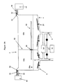
- Figure 2 shows a container having adapters for connecting lumen devices. Similar to the container of figure 1a, container 2 shown in figure 2 has a sloped bottom wall 4 with a first fluid port 6 at the lowest point of the sloped bottom wall 4. Several stirrers are installed on the sloped bottom wall 4. A flat sheet metal grid 28a is horizontally located at the lower portion of container 2. Grid 28a, sloped bottom wall 4, and side walls of container 2 define a space accommodating stirrer 20 and wells 18 on plate 17. An adapter 40 is connected to a second fluid port 42 at one end and the other end for receiving a lumen device 46. A gas-tight seal, tight-fitting, or loose-fitting between adapter 40 and lumen device 46 can be formed.
- the contact surface of opening 56 can be made of an uneven surface so that, when opening 56 is closed around a lumen device, the uneven surface will provide passage to allow both liquid and gas to pass therethrough while holding the lumen device.
- the occlusion area on the lumen device surface can be significantly reduced.
- the uneven surface may have textures, projections, sharp edges, or sharp points thereon.
- the lower grid 28a and the upper grid 28b are a flat metal sheet and horizontally positioned at the lower and the upper portion of the container 2, respectively.
- Stirrers 20 are located below the lower grid 28a.
- Interface 52 has an opening (or holder) 56 for holding a lumen device 46.
- the opening 56 can be configured in many different ways such as those described with Figs. 3b-3f.
- a plurality of transducer 16 is provided to generate ultrasonics. Accordingly, the space between outer surface of the bottom of container 2 and the inner surface of the bottom wall of vacuum chamber 66 is filled with water or other suitable liquids providing a medium for the ultrasonics.
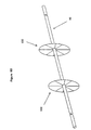
- Figure 5c shows two holders 100 of plate type holding a lumen device 46.
- Each of holders 100 can be constructed in the way as described previously with figures 3d-3g.
- the gap (the opening for passing the lumen device) formed between the two plates of one holder 100 forms an angle with that of the other holder 100 of the two holder structure.
- the angle is 90 degree as shown in figure 5c.
- the two holders 100 are preferably positioned close enough so that when the expandable material 60 lined in the gap (opening) is expanded, the expandable material 60 will also expand outwardly away from the two plates and become in contact with the other holder 100, thus help seal the gap of the other holder 100.
- This configuration provides an advantage that no complete seal is needed for a single holder, yet a good seal such as a gas-tight seal can be achieved when two such holders are combined. It has been noted by the applicants that, when a cylindrical lumen device is placed across the gap between the two plates of holder 100, areas on the outer surface of the lumen device, where the diameter of the cylindrical lumen device is parallel to the gap, are more difficult to seal because the expandable material 60 has to expand extra distance to cover those areas. By providing two closely positioned holders 100 with the two gaps forming an angle, the above mentioned areas in each of the two holders can be sealed by the other holder. Therefore, the requirement to the expandable material can be lowered without sacrificing the sealing characteristics.
- Plate 59d can be secured and sealed to the bottom and side walls of container 2 with its upper edge or surface equipped with a layer of expandable material 60.
- a third plate 59e is located above and aligned with second plate 59d.
- the third plate can be made a part of the lid for container 2.
- the lower edge of plate 59e and the upper edge of plate 59d form a gap for passing a lumen device.
- the edges of the third plate is also provided with a layer of expandable or other sealing material 60.
- the second plate 59d and the third plate 59e lie in one vertical plane, and the first plate 59c lies in another vertical plane parallel to that containing second plate 59d and third plate 59e.
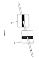
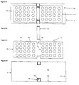
- edge 114 of seat 112 and edge 120 of plate 118 can be used for edge 114 of seat 112 and edge 120 of plate 118, as long as the shape matches that of the exterior and interior periphery of tray 110.
- the open rectangular formed by edge 114 and edge 120 shown in figure 7b is modified by making the upper edge longer than the bottom edge of the open rectangular and tray 110 has a corresponding shape. This configuration makes it easier to the plate 118 down into tray 110 and seal it.
- Plate 118 can further include an opening 56 of any kind as discussed previously with figures 3b-3g. Opening 56 can be located in plate 118 or on edge 120 facing the bottom of tray 110 where lumen device is placed.
- a layer of expandable, compressible, or other suitable sealing material is also provided with tray 110 along the interior periphery where plate 118 is inserted.
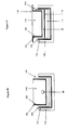
- Figure 7c shows another embodiment in which tray 110 has a partition 111 therein.
- Partition 111 can be made as part of the tray 110.
- Upper edge 111a of partition 111 has a layer of expandable, compressible, or other suitable sealing material.
- Partition 111 is aligned with plate 118 so that when plate 118 is inserted into tray 110 seal can achieved between upper edge 111a of partition 111 and lower edge of plate 118, and a lumen device can be placed through the gap or opening 56 formed between upper edge 111a of partition 111 and lower edge of plate 118.
- tray 110 and interface 52 in the contact area between tray 110 and interface 52 (or plate 112 and 118), a portion of side and bottom walls of tray 110 is removed so that in those portion the sealing layer 116 of tray seat 112 and the sealing layer 122 of plate 118 of the interface 52 are in direct contact.
- Plate 118 can be secured to a lid or cover 119 for container 2 and, a portion of the lower surface of the cover 119 is provided with a layer of expandable, compressible, or other suitable sealing material to seal the upper edge of the tray 110 and the container 2 as shown in figure 7c.
- a removable plate 118 with a layer of sealing material on its contact edge is inserted into tray 110 through a rail defined by extruding edge 137.
- each side wall 141 is provided with a stopper, such as an extrusion, to confine the movement of tray 110 along a direction perpendicular to interface 52.
Abstract
Description
- This invention relates to systems and processes for cleaning, chemical sterilizing or disinfecting medical devices.
- Medical instruments have traditionally been sterilized or disinfected using either heat such as is provided by steam, or a chemical in liquid, gas, or vapor state. Prior to sterilization or disinfection, the instruments to be treated are usually first cleaned and then sterilized or disinfected. After sterilization or disinfection with a liquid chemical germicide, purified water is used to rinse the instruments and then the instruments are dried. Numerous publications regarding the cleaning of medical devices and the sterilizing of medical devices are available.
- U.S. Patent No. 5,443,801 discloses a transportable cleaning/sterilizing apparatus and method for inside-outside washing and sterilization of medical/dental instruments. The apparatus functions in four sequential cycles: wash, rinse, sterilize, and dry. The sterilization step is conducted using ozonated and purified water, and the drying step is accomplished by injecting ozonated/deozonated sterile warm dry oxygen, or sterile inert gas into and exhausted from the wash chamber under a positive pressure relative to atmospheric. In this process, the device has to be rinsed with purified water after it is sterilized to remove sterilant residue before drying step.
- U.S. Patent No. 5,505,218 to Steinhauser et al. discloses a device for cleaning, disinfecting and maintaining medical or dental instruments. The device has a pot-shaped container with a multiplicity of mountings in the interior of the container each for one of tool holder, a water supply system, a compressed air supply system, and an ultrasonic transducer. The disinfection is conducted with heated water, and the drying is conducted with hot compressed air. This system is not designed for sterilization.
- U.S. Patent No. 5,279,799 to Moser et al. discloses apparatus for cleaning and testing endoscopes by injecting pressurized air into the sheath and pressurized air and washing liquid into the ducts. A washing chamber is provided which contains retractable cages to hold the endoscopes during cleaning and testing. This process includes washing, disinfecting, final rinsing with purified water, and air drying the ducts of a tubular article. A number of filters are involved in this system, and this system is not designed for sterilization.
- U.S. Patent No. 4,744,951 to Cummings et al. discloses a two-chambered system which provides hydrogen peroxide in vapor form for use in sterilization processes. The sterilant is initially vaporized in one chamber and then applied to the object to be sanitized in another single sterilizing chamber, thereby producing a concentrated hydrogen peroxide vapor which is relatively more effective. The sterilization processes are designed for furnishing concentrated hydrogen peroxide vapor to interior surfaces of articles having a tortuous or a narrow path. However, the sterilization processes are ineffective at rapidly sterilizing lumened devices, since they depend on the diffusion of the hydrogen peroxide vapor into the lumen to effect sterilization.
- U.S. Patent No. 4,863,688 to Schmidt et al. discloses a sterilization system consisting of a liquid hydrogen peroxide vaporization chamber and an enclosure for sterilization. The enclosure additionally may hold containers wherein the hydrogen peroxide sterilant vapor does not contact the interior of the containers. This system is designed for controlling the exposure to the hydrogen peroxide vapor. The system is not designed for sterilizing a lumen device.
- U.S. Patent No. 4,943,414, entitled "Method for Vapor Sterilization of Articles Having Lumens," and issued to Jacobs et al., discloses a process in which a vessel containing a small amount of a vaporizable liquid sterilant solution is attached to a lumen, and the sterilant vaporizes and flows directly into the lumen of the article as the pressure is reduced during the sterilization cycle. This system has the advantage that the water and hydrogen peroxide vapor are pulled through the lumen by the pressure differential that exists, increasing the sterilization rate for lumens, but it has the disadvantage that the vessel needs to be attached to each lumen to be sterilized.
- U.S. Patent Nos. 4,937,046, 5,118,471 and 5,227,132 to Anderson et al. each disclose a sterilization system which uses ethylene oxide gas for sanitation purposes. The gas is initially in a small first enclosure and thereafter slowly permeates into a second enclosure where the objects to be sterilized are located. A medium is then introduced into the second enclosure to flush out the sterilizing gas into a third enclosure containing the second enclosure. An exhaust system then exhausts the sterilant gas and air from the third enclosure. These systems also have the disadvantage of relying on the diffusion of the sterilant vapor to effect sterilization and hence are not suitable for rapidly sterilizing lumened devices.
- U.S. Patent No. 5,122,344 to Schmoegner discloses a chemical sterilizer system for sterilizing items by vaporizing a liquid chemical sterilant in a sterilizing chamber. Pre-evacuation of the sterilizer chamber enhances the sterilizing activity. Sterilant is injected into the sterilizer chamber from a second prefilled shot chamber. This system also relies upon diffusion of sterilant vapor to effect sterilization and is also not suitable for rapidly sterilizing lumened devices.
- U.S. Patent No. 5,266,275 to Faddis discloses a sterilization system for disinfecting instruments. The sterilization system contains a primary sterilization chamber and a secondary safety chamber. The secondary safety chamber provides for sensing and venting to a destruction chamber any sterilization agent that is released from the primary sterilization chamber. This system, as in other systems, also relies upon diffusion of sterilant vapor to effect sterilization and is also not suitable for rapidly sterilizing lumened devices.
- In U.S. Patent Nos. 5,492,672 and 5,556,607 to Childers et al, there is disclosed a process and apparatus respectively for sterilizing narrow lumens. This process and apparatus uses a multicomponent sterilant vapor and requires successive alternating periods of flow of sterilant vapor and discontinuance of such flow. A complex apparatus is used to accomplish the method. Additionally, the process and apparatus of'672 and '607 require maintaining the pressure in the sterilization chamber at a predetermine subatmospheric pressure.
- In U.S. Patent No. 5,527,508 to Childers et al., a method of enhancing the penetration of low vapor pressure chemical vapor sterilants into the apertures and openings of complex objects is disclosed. The method repeatedly introduces air or an inert gas into the closed sterilization chamber in an amount effective to raise the pressure to a subatmospheric pressure to drive the diffused sterilant vapor further into the article to achieve sterilization The '508, '672 and '607 Childers inventions are similar in that all three require repeated pulsations of sterilant vapor flow and maintenance of the sterilization chamber pressure at a predetermined subatmospheric pressure.
- One disadvantage of the cleaning/sterilizing or cleaning/disinfecting systems of the prior art as discussed above is that, after the device is sterilized or disinfected and before it is dried, the device has to be rinsed with purified water to remove disinfectant or sterilant residues. A so-called bacteria filter is usually used to filter the water to remove particulates and bacteria. Typically, a two-stage filtering system is utilized, for example, a first stage has a 2-5 micron filter and a second stage has a 0.1-0.2 micron filter. However, virus can be smaller than 0.1 micron. This means the virus can penetrate the filtering system recontaminating the sterilized device in the final rinsing process. Another problem associated with the use of a bacteria filter is that bacteria can form biofilms in the filter which are difficult to sterilize and, thus, become a new potential source of contamination.
- In consideration of the foregoing, no simple, safe, effective method of cleaning, sterilizing or disinfecting, drying devices with an integrated process and with the sterilizing (or disinfecting) and drying being conducted simultaneously exists in the prior art. Thus, there remains a need for a simple and effective process and apparatus for efficiently cleaning, sterilizing or disinfecting, and drying medical devices, especially those with long narrow lumens.
- One aspect of the present invention provides a cleaning/sterilizing or cleaning/disinfecting process which incorporates cleaning, sterilizing (or disinfecting) and drying of a lumen or non-lumen medical device into an integrated process, i.e. the device is cleaned, sterilized and dried in situ in the same apparatus in a operation cycle. Especially, the sterilizing and drying are conducted simultaneously. In other words, after the device is sterilized, there is no need to further rinse the sterilized device like the prior art does. Thus, there is no need for a filtering system.
- Another aspect of the present invention relates to an apparatus for cleaning, sterilizing, or disinfecting medical devices, especially devices with lumens. The apparatus comprises a container with an interface for separating the container into enclosures. The interface has an opening equipped with specially designed holder(s) for eliminating or reducing occlusion area.
- Still another aspect of the present invention relates to a multi-compartment container. The container has a specially designed tray for accommodating a lumen device. The tray is placed across and sealed against an interface separating the container into enclosures.
- The method of the present invention for cleaning/sterilizing or cleaning/disinfecting a device having a lumen with at least two open ends comprises the steps of: a) providing a container having at least one enclosure and at least one interface separating the enclosure from the container, the interface having at least one opening thereon, b) placing the device across the opening with one open end in the container and another open end in the enclosure, c) generating a flow of a cleaning solution through the lumen to clean the inner surface of the lumen, d) generating a flow of rinse solution through the lumen to rinse the inner surface of the lumen, e) treating the device with a chemical germicide, and f) adjusting the opening in any of steps c) to e) to reduce areas on outer surface of the device which are occluded from exposure to the cleaning solution, the rinse solution, or the chemical germicide by contacting with the opening, or to expose the areas to the cleaning solution, the rinse solution, or the chemical germicide. In the method, one or more steps can be repeated. In the method, along its passage, the opening has at least two independently controllable apertures for holding and sealing the device. In the method, the step of adjusting the opening comprises opening one of the two apertures while closing the other aperture so that the areas on the outer surface of the device occluded by the two apertures are alternately exposed to the cleaning solution, the rinse solution, or the chemical germicide in step c), d), or e), respectively. The method further comprises retaining a predetermined amount of the chemical germicide in the container and enclosure and vaporizing the retained chemical germicide to sterilize (or disinfect) and dry the device under vacuum during or after step e). In the method, the sterilizing or disinfecting can be conducted under a diffusion restricted environment, or by reducing pressure to a first predetermine pressure followed by further reducing the first pressure to a predetermined second pressure, or at controlled pump down rate. In the method, the sterility of said device can be maintained in the container and enclosure after the device is sterilized and dried. The method further comprises removably attaching the container to a vacuum system for applying vacuum to the container or enclosure and detaching the container after the device is sterilized (or disinfected) and dried. In the method, the flow through the lumen can be generated by applying a pressure higher than atmospheric pressure at one end of the lumen, or by applying vacuum to one end of the lumen device. In the method, the opening of the interface has separately controllable and moveable contact points, and the adjusting step comprises controlling the contact points so that a different portion of the contact points is made in contact with the device alternately. In the method, the opening forms a seal around the device selected from the group consisting of a gas-tight seal, a tight-fining seal, or a loose-fining seal. In the method, a non-lumen device also can be treated together with the lumen device.
- An apparatus of the present invention for cleaning/sterilizing or cleaning/disinfecting a lumen device having at least two open ends comprises a container having a fluid port for flowing and draining a fluid in and out the container. At least one enclosure is coupled with the container for receiving part of the lumen device so that one end of the lumen device is located in the enclosure and the other end of the lumen device is located in the container. An interface separates the container and enclosure, and the interface has at least one opening. At least one openable and closable holder sealably is coupled to the opening. A source for creating a pressure difference between the two open ends to generate a flow through the lumen of the lumen device is provided. A cleaning mechanism adapted to clean the device in the container or enclosure is also provided. Preferably, the interface is removable. The holder can be a shutter. The holder can be equipped with expandable or compressible material on its contact surface with the device. In one embodiment, the holder has two plates forming a gap therebetween for passing the device, the surfaces of the plates facing the gap are equipped with expandable or compressible material. In another embodiment, two independently controllable holders are sealably arranged along the passage of the opening. Each one of the two holders comprises two plates forming a gap therebetween for passing the device, the surfaces of the plates facing the gap are equipped with expandable or compressible material. Preferably, each of the gaps defines an elongate cross section having a longitudinal axis as viewed from a direction perpendicular to the surface of the plates, the longitudinal axis of one gap forms an angle with that of the other gap, and the two holders are placed close enough to each other for the expandable material on one holder to be brought in contact with the other holder when the expandable material is expanded. The apparatus further comprises a vacuum system, the container comprises a gas-permeable and microorganism-impermeable barrier and is detachably coupled to the vacuum system. The gas-permeable and microorganism-impermeable barrier can be equipped with a valve for opening and closing gas communication between the container and the vacuum system or between the container and atmosphere through the barrier. The cleaning mechanism is selected from the group consisting of a stirrer, a liquid jet, an air jet, ultrasonics, or a bubble generator. The interface may comprise a first plate having a plurality of openings with elongate cross section, and at least two other plates forming a gap along a longitudinal direction, the plates are configured so that the longitudinal direction of the gap and the longitudinal direction of the elongate cross section of the opening form a substantially right angle. In another embodiment, the container has a first enclosure sharing with the container a first interface having a first opening and a second enclosure sharing with the first enclosure a second interface having a second opening, wherein the device is placed across the first and second interface through the first and second opening so that one open end of the device is located in the container and the other open end of the device is located in the second enclosure. In the apparatus of the present invention, the holder has multiple contact points on its inner surface for holding the device, and the contact points are separately controllable and moveable.
- Figure 1a is a schematic diagram of a container used in a cleaning/sterilizing process of the present invention.
- Figure 1b is a schematic diagram of a stirrer with fluid inlets used in the container of Figure 1.
- Figure 1c is a schematic diagram of a gas-permeable but microorganism-impermeable barrier installed in a vacuum port of the container of Figure 1.
- Figure 1d is a schematic diagram of a container placed in a vacuum chamber used in a cleaning/sterilizing process of the present invention.
- Figure 1e is a schematic diagram of a container with fluid jet tubes.
- Figure 2 is a schematic diagram of a container with an adaptor used in the cleaning/sterilizing process of the present invention.
- Figure 3a is a schematic diagram of a container with an interface used in the cleaning/sterilizing process of the present invention.
- Figure 3b is a schematic diagram of a shutter used in the interface of the container of figure 3a.
- Figure 3c is a schematic diagram of a iris valve used in the interface of the container of figure 3a.
- Figures 3d, 3e, and 3f are schematic diagrams of two plates forming an opening in the interface of the container of figure 3a.
- Figure 3g is schematic diagram of an interface of the container of figure 3a.
- Figure 4 is a schematic diagram of a container placed in a vacuum chamber used in the process of the present invention.
- Figure 5a is a schematic diagram of a container having two holders in an interface.
- Figures 5b and 5c are schematic diagrams of two holders of the container shown in figure 5a holding a lumen device.
- Figure 5d is a schematic diagram of an interface of a container with multiple openings.
- Figure 6 is a schematic diagram of a container separated into three enclosures by two interfaces according to the present invention.
- Figure 7a is a schematic diagram of a container having an interface and a tray across the interface according to the present invention.
- Figures 7b and 7c are cross-sectional views of the container of figure 7a at the location of the interface.
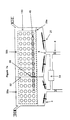
- Figure 8a is a top view of the container of figure 7a
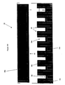
- Figure 8b is a top view of a portion of the interface of figure 7a.
- Figure 8c is a top view of the tray of figure 7a.
- Figure 8d is a top view of the container of figure 7a without the tray and the interface.
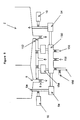
- Figure 9 is a schematic diagram showing a recycle system for processing liquid.
- The cleaning/sterilizing or cleaning/disinfecting process of the present invention can be carried out with various apparatus and incorporated with various sterilization methods, which are described below.
- This method can be incorporated into the cleaning/sterilizing or cleaning/disinfecting process of the present invention. In order to maximize the efficiency of a vapor sterilization process, it is important and desirable to drain excess sterilant solution and only keep a desired amount of the sterilant solution to vaporize after treating a device to be sterilized with the sterilant solution.
- According to the present invention, a sterilization container or enclosure may have a surface with wells thereon which define a known volume. The well is positioned so that when a liquid sterilant is introduced onto the surface, a known volume of the liquid sterilant fills the well and when the liquid sterilant is drained from the surface, the known volume of liquid sterilant remains in the well so that a subsequent vapor sterilization process can be performed on the device with the known volume of liquid sterilant positioned within the surface. The surface preferably has at least one perforation for draining the liquid sterilant from the surface. The well formed in the surface can be curved, flat or angled. Thus, the well can be an inwardly extending hemispherical projection. The well can also be formed in the surface as an inwardly extending rectangular projection having rounded ends. The well formed in the surface can also be a rectangular box having side walls, defining an opening. Where perforations are provided, they can be disposed adjacent the well, and can be roughly spherical in shape. The upwardly extending projection can include a perforation thereon, which can be on top of the projection or on a side of the projection. The surface can be a sloped surface, a convex or concave surface or a V-shaped surface. The surface can be made of a variety of materials including stainless steels, aluminum, aluminum alloys, liquid crystal polymers, polyesters, polyolefins polymers or fluorinated polyolefins. If the surface is comprised of a composite material, the composite material can include a filler of high thermal conductivity. Examples of composite materials include a metal-filled polymer, a ceramic-filled polymer and a glass-filled polymer. Those materials are also suitable for the side walls and doors of the sterilization container.
- A tray with wells with configurations similar to that described above can be provided with a container or enclosure. The tray can be secured to the container or removably placed in the container.
- A method of vapor sterilization or disinfection under diffusion-restricted environments can also be used in corporation with the cleaning/sterilizing or cleaning/disinfecting process of the present invention. In this method, the devices (lumen or non-lumen) to be sterilized are pretreated with a sterilant solution, and then exposed to pressures less than the vapor pressure of sterilant. Both the exterior and interior surface areas of a lumen or non-lumen device can be effectively sterilized by taking advantage of the diffusion-restricted environments within lumens or within a container or enclosure.
- As used herein, a "diffusion-restricted" area refers to any one or more of the following properties: (1) the ability of the area of an article placed within the sterilization system of the present invention to retain 0.17 mg/L or more hydrogen peroxide after one hour at 40°C and 10 torr; (2) having the same or more diffusion restriction than provided by a single entry/exit port of 9 mm or less in internal diameter and 1 cm or greater in length; (3) having the same or more diffusion restriction than provided by a lumen 27 cm in length and having an internal diameter of 3 mm; (4) having the same or more diffusion restriction than provided by a lumen having a ratio of length to internal diameter greater than 50; (5) the ability of an article placed within the sterilization system of the present invention to retain 17% or more of the starting 1 mg/L hydrogen peroxide solution initially placed therein after one hour at 40°C and 10 torr; or (6) being sufficiently diffusion-restricted to completely sterilize a stainless steel blade within a 2.2 cm by 60 cm glass tube having a rubber stopper with a I mm by 50 cm stainless steel exit tube therein at a vacuum of 10 torr for one hour at 40°C in accordance with the present invention. It is acknowledged that characteristics (1) and (5) will vary depending on the initial concentration of hydrogen peroxide placed into the article; however, this can be readily determined by one having ordinary skill in the art.
- This method includes the steps of contacting the exterior and interior of a device with a sterilant solution, and then exposing the device to a negative pressure or vacuum for a period of time sufficient to effect complete sterilization. For example, when 1 mg/L of hydrogen peroxide is used as sterilant, if the exposing step is conducted for 1 hour at 40°C and 10 torr, the diffusion restricted area preferably retains 0.17 mg/L or more hydrogen peroxide, or retains 17% or more of the hydrogen peroxide placed therein after the exposing step. In certain preferred embodiments, the diffusion-restricted area has the same or more diffusion restriction than provided by a lumen 27 cm in length and an internal diameter of 3 mm, or has the same or more diffusion restriction than provided by a lumen having a ratio of length to internal diameter greater than 50. The contacting step can be performed by either a direct or an indirect contact procedure. Direct contacting includes methods such as injection, static soak, flow-through, condensation of a vapor, or aerosol spray, or mist spray. Any other methods involving physically contacting the devices to be sterilized with a sterilant would be considered direct contacting. Indirect contacting includes those methods in which sterilant is introduced into the chamber or container, but not directly on or on the devices to be sterilized. The exposing step is preferably performed for 60 minutes or less, and is preferably performed at a pressure less than the vapor pressure of the sterilant. Thus, the preferred pressure range under conditions of the present invention is between 0 and 100 torr. The exposing step can include the step of heating the device, such as by heating the container in which the exposing step occurs. The container can be heated to about 40°C to about 55°C. Alternatively, the sterilant solution can be heated, such as to a temperature of about 40°C to about 55°C. Optionally, the step of exposing the device to a plasma can be conducted during the step of exposing the device to negative pressure or vacuum. In one embodiment employing exposure to plasma, the method is performed within a first chamber and the plasma is generated in a second separate chamber. This embodiment further comprises the step of flowing the plasma into the first chamber. Advantageously, the contacting and/or exposing steps of the method can be repeated one or more times.
- The cleaning/sterilizing process of the present invention can also be carried out in cooperation with a controlled pump down method without relying on a diffusion-restricted environment.
- Effective sterilization results similar to those created in diffusion-restricted environments can be created through controlling the evacuation rate of a chamber or container in which devices to be sterilized are placed. Thus, in one embodiment of the present invention, this controlled pump-down rate method comprises the steps of contacting the device with a liquid sterilant at a first pressure; draining excess liquid sterilant to retain a predetermined amount of the sterilant, and decreasing the pressure of the chamber to a second pressure below the vapor pressure of the liquid sterilant in which at least a portion of the decrease in pressure below about the vapor pressure of the liquid sterilant occurs at a pump down rate of less than 0.8 liters per second, calculated based on the time required to evacuate the chamber from atmospheric pressure to 20 torr when the chamber is empty and dry, i.e. when the chamber has neither devices to be sterilized nor a visible quantity of liquid within it. According to one aspect of this preferred embodiment, at least the decrease in pressure below about two times the vapor pressure of the liquid sterilant occurs at a pump down rate of less than 0.8 liters per second. According to another embodiment, the decrease in pressure below about four times the vapor pressure of the liquid sterilant occurs at a pump down rate of less than 0.8 liters per second. Preferably, the pump down rate is 0.6 liters per second or less; more preferably, 0.4 liters per second or less; and most preferably, 0.2 liters per second or less. Advantageously, the first pressure is atmospheric pressure. Preferably, the liquid sterilant is hydrogen peroxide. The hydrogen peroxide usually is a solution as used in the art, preferably it is a 3-60% solution. The device can be a lumen or non-lumen medical instrument.
- The present invention can also incorporate a method for sterilizing a device comprising the steps of (a) contacting the device with liquid sterilant at a first pressure; (b) retaining a predetermined amount of the liquid sterilant in the container; (c) pumping down the container or chamber to a second pressure which is lower than the first pressure at a first rate; and (d) pumping down the container or chamber to a third pressure which is lower than the second pressure, wherein at least a portion of the pumping down to the third pressure is at a second rate which is slower than the first rate. The pump down rate either above and/or below the second pressure can be constant or variable. In certain embodiments, the pump down rate either above and/or below the second pressure is reduced in stepwise fashion. Preferably, the second pressure is greater than or equal to about the vapor pressure of the liquid sterilant; more preferably, the second pressure is greater than or equal to about two times the vapor pressure of the liquid sterilant; most preferably, the second pressure is greater than or equal to about four times the vapor pressure of the liquid sterilant. Advantageously, the pump down rate in step (d) is 0.8 liters/sec or less; more advantageously 0.6 liters/sec or less; even more advantageously 0.4 liters/sec or less; and most advantageously 0.2 liters/sec or less, calculated based on the time required to evacuate the chamber from atmospheric pressure to 20 torr under empty and dry conditions. Preferably, the liquid sterilant is hydrogen peroxide. In another embodiment, the device is a medical instrument having a lumen. Preferably, the pumping down of step (c) reduces the pressure to less than about three times, more preferably to less than about two times, the vapor pressure of the liquid sterilant.
- Another suitable method includes contacting the device with liquid sterilant, retaining a predetermined amount of the liquid sterilant in the container, and reducing the pressure of the chamber while regulating the pump down rate so as to control the evaporation rate of sterilant in said chamber. In any of the methods described above, the contacting step may comprise application of liquid or condensed vapor. These methods described above may additionally comprise further evacuating the chamber to remove residual sterilant. Further, these methods described above may additionally comprise exposing the device to plasma to remove residual sterilant or enhance sterilization efficacy. The contacting step in these methods can be either by direct or indirect contacting. As stated herein, indirect contacting involves introducing sterilant into the chamber without directly contacting the device to be sterilized.
- A two step pump down sterilization method can also be used in cooperation with the cleaning/sterilizing process of the present invention. This method comprises the steps of contacting a device with liquid sterilant; draining excess liquid sterilant to retain a predetermined amount of the sterilant; bringing the pressure of the chamber to a first pressure range at which the liquid sterilant is vaporized from non-diffusion restricted area of the device to sterilize the non-diffusion restricted area; bringing the pressure of the chamber to a second pressure range at which the liquid sterilant is vaporized from diffusion restricted area of the device to sterilize the diffusion restricted area, wherein the minimum pressure in the second pressure range is lower than the maximum pressure in the first pressure range.
- Preferably, the first pressure range is from 20 to 760 torr; more preferably, the first pressure range is 20 to 80 torr; most preferably, the first pressure range is 40-50 torr. Advantageously, the second pressure range is 1-30 torr; more advantageously, the second pressure range is 5-10 torr. In one preferred embodiment, the device includes a diffusion-restricted environment. Preferably, the device is a medical instrument with a lumen. Advantageously, the sterilant is hydrogen peroxide. According to another aspect of this preferred embodiment, the chamber is at a set temperature and wherein the first pressure is preferably lower than the vapor pressure of the sterilant at the set temperature. Preferably, the pressure of the chamber is maintained constant at the first pressure for a time period sufficient to sterilize the non-diffusion restricted area. Advantageously, the pressure of the chamber is maintained constant at the second pressure for a time period sufficient to sterilize the diffusion restricted area. The pressure of the chamber may be permitted to increase after reaching the first or second pressure range as a result of vaporization of the sterilant within said chamber. Alternatively, the pressure of the chamber is permitted to decrease after reaching the first or second pressure through pumping of said chamber at a rate slower than used to decrease the pressure between said first and second pressure ranges. Preferably, the contacting step is with liquid, condensed vapor, or mist The method can also include the steps of bringing the pressure to a third pressure lower than the second pressure to remove residual sterilant and/or exposing the device to plasma to remove residual sterilant or enhance sterilization efficacy.
- A method of directly flowing fluid through a lumen of a medical device to be treated can be incorporated with the cleaning/sterilizing or cleaning/disinfecting process of the present invention. An apparatus can be used to efficiently clean and sterilize devices with long narrow lumens by flowing a fluid such as a cleaning solution or a sterilant, either in liquid phase or in vapor phase, or a plasma gas directly through the lumens of lumen devices to be sterilized.
- The flow of a germicide (solution or vapor), or any cleaning solution through a lumen of a medical device is driven by a pressure drop between two open ends of the lumen. The pressure drop can be generated by applying either a vacuum or a high pressure at one end. By generating a forced flow through a pressure differential other than relying on diffusion, the sterilization rate is significantly increased and less time is needed for a sterilization cycle.
- It is clear that the two ends of the lumen need to be exposed to a pressure differential. This is achieved in the present invention by placing a sealable interface between two chambers, two enclosures, or a container and an enclosure to separate them from each other. Preferably, an opening is provided in the interface and the lumen device to be sterilized is placed through the opening so that the lumen serves as a flow path between the two chambers or between the container and the enclosure.
- The opening can be constructed in several ways. One way to achieve this is with a camera shutter approach employing an iris diaphragm, such as a precision iris diaphragm from Edmund Scientific. An optional spring can be used to secure the closure of the shutter. Also commercially available is Syntron Iris Flow Control Valve manufactured by FMC Corporation. This Iris Valve has a sleeve made of Teflon or other synthetic material defining an aperture. By rotating two ends of the sleeve relative to each other, the aperture can be reduced or increased. Iris diaphragm valves from Kemutec Inc. are also commercially available which can be automatically controlled. Another example is the AirGripper and AirPicker manufactured by Firesone Industrial Products Company. Another way to construct an openable and closeable opening is to employ two plates. Two edges of the two plates form a gap which can be adjusted by moving the two plates relative to each other. One or more lumen devices are placed through the gap formed between the two plates and the two plates are moved together to form a seal around the lumen devices. The edges of the two plates forming the gap can be equipped with compressible material or expandable material. When expandable material is used, a fluid source can be provided to expand the expandable material. Optionally, a porous material like a sponge or air permeable material may be utilized on the edges. In this case some sterilant can diffuse through the porous material to the outer surface of the lumen device occluded by the closed opening. However, most the sterilant flows through the lumen device. Another usable interface is a hole or a slot, the hole or slot is equipped with gas or liquid inflatable material so that by inflating the inflatable material on the hole or the slot the opening is reduced and the lumen device is held and sealed. Still another option is to place a compressible material on top of an expandable or inflatable material so as to facilitate the sealing around the lumen device.
- The closing and opening movement of the opening can be controlled mechanically or electronically with any conventional mechanism. The degree of opening is adjustable. Thus, it can be sealed to a different degree between the opening and the lumen device depending on the desired purpose. For example, the opening can form a gas-tight seal, a tight-fitting seal, or a loose-fitting seal around the lumen device. As used herein, a gas-tight seal refers to a seal that substantially stops liquid and gas flow through the contact area between the opening and the lumen device surface. When a gas-tight seal is employed, preferably the device to be sterilized is first pre-cleaned so that the occluded area by the seal is cleaned before the gas-tight seal is formed. A loose-fitting seal allows both liquid and gas to flow through the gap between the opening and the lumen device surface, and in the meantime is able to maintain a pressure drop across the interface enough to generate a flow through the lumen. A tight-fitting seal allows gas and liquid to penetrate to the contact area between the opening and the lumen device surface by diffusion. For example, a tight-fitting seal can be formed with porous material or textures provided on the contact surface of the opening. Thus, for gas-tight seal the device is held tightly by the closed opening. In the tight-fitting seal, the closed opening also holds the device in position. In the case of a loose-fitting seal, the device can move relative to the opening, but is not flashed away.
- The interface can be made openable, closeable, and removable, and may have more than one opening. In order to promote sterilization efficiency, all the sterilization apparatus of the present invention can be further equipped with a heater and/or a plasma.
- As used herein, the terms "container" and "enclosure" are exchangeable. The present invention provides a container specially designed to eliminate or minimize occlusion area which usually corresponds to the contact area between a lumen device surface and a closed opening of an interface holding the device. The occlusion area is hard to reach by either liquid or vapor because of the close contact between two surfaces. Thus, the cleaning and sterilizing of an occlusion area is adversely affected by such contact. Several approaches have been taken in the present invention to deal with this occlusion problem.
- One approach is to reduce the contact area by using porous material, textures, sharp projections, or sharp edges on the contact surface of the opening of the interface, or an adaptor or a connector. In this way, cleaning and sterilizing fluid can either flow or diffuse to most part of the contact surface of the device which is held by the closed opening fairly tightly and, in the meantime, the contact area between the opening and the device surface will impose a resistance to fluid flow high enough to allow a pressure difference to exist between two sides of the interface. Thus, a flow through the lumen of the device can be generated and maintained if desired. Another advantage of this approach is that the contract area generated through the above means can be controlled to provide a diffusion restricted environment at the contact area, which will increase the efficiency of the sterilization process.
- Another approach is to use multiple holders in the opening. For example, two holders can be secured to the opening along its passage. Preferably, each of the holders is independently controllable and sealable. During a cleaning or sterilizing process, the two holders are alternately opened and closed, i.e. one is open while the other is close. In this way, a good seal between the two sides of the interface can be maintained and the device can be held tightly during a sterilization process. Meanwhile, the contact areas on the device surface caused by the two holders are exposed to cleaning or sterilizing fluid alternately.
- Still another approach is the combination of the above two approaches. In this approach, the contact surface of the interface, or the opening, or the holder has multiple contact points. The contact points can be projections, teeth, blades, sharp edges, or any other suitable form and shape. These contact points can be controlled separately so that a portion of the contact points is made in contact with the device to be sterilized while the others are not. By alternately changing the position of the contact points, all the occlusion areas will be exposed to the sterilant. An example of such a multiple contact point structure is a shutter with multiple blades. Those blades can be separately controlled for opening and closing.
- The present invention also provides a container with a specially designed tray. It is often desirable to place the device to be sterilized on a tray so that after the device is cleaned and sterilized, it can be transported on the tray without being touched. This reduces the chance of contamination through touching the device. In the apparatus of the present invention, a tray is placed across an openable and closeable interface between a container and an enclosure or between two compartments or enclosures, a lumen device is placed on the tray also across the interface. When the interface is in a closed condition, a seal is formed between the opening of the interface and the tray and the lumen device.
- Various apparatus of the present invention which can be used to carry out the cleaning/sterilizing or cleaning/disinfecting process of the present invention is described in more detail by reference to the drawings. In the following figures like numbers refer to like parts throughout.
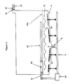
- Figure 1a shows a
container 2 used in a cleaning/sterilizing process of the present invention.Container 2 has a slopedbottom wall 4 leading to afluid source 7. Afluid port 6 is provided at the lowest point of slopedbottom wall 4. Apparently, slopedbottom wall 4 can be configured differently and the lowest point can be located in any location within the slopedbottom wall 4. For example, instead located in the position as shown in figure 1a, the lowest point, thus thefluid port 6, can be located at one end or a corner of the slopedbottom wall 4. Avalve 8 is provided atfluid port 6 to control fluid flow in and outcontainer 2. Below slopedbottom wall 4 is a flat lower bottom 14. The lower surface of the slopedbottom wall 4 is equipped with a number oftransducer 16 for providing ultrasonic cleaning. A number ofwells 18 are provided on aplate 17 located above the upper surface of the slopedbottom wall 4 and below rotatingarm 22.Plate 17 can be of any appropriate shape and made rotatable, so that unwanted liquid retained inwells 18 can be removed by rotatingplate 17. Well 18 can have different shapes and is capable of retaining a predetermined amount of sterilant as described earlier.Plate 17 can be removably placed on the upper surface of the slopedbottom wall 4 or secured to the upper surface in a horizontal orientation. One ormore stirrer 20 is installed either on slopedbottom wall 4 or on anupper wall 24 or on both. Rotatingarm 22 of thestirrer 20 can be made hollow or contains channels connecting to an outside fluid source through the body of thestirrer 20. As shown in figure 1b,stirrer 20 can be connected to awater source 21a, anair source 21b, and adrain 21c, each of them is controlled by a valve. Water jet orair jet 26 can be provided through the channels of rotatingarm 22.Container 2 can also be made of jacket walls with holes thereon so that the water or air jet can be provided through those holes opened on the jacket walls.Container 2 also has alower grid 28a and anupper grid 28b. Preferably,grid container 2 at an upper and a lower position, respectively. A space defined bylower grid 28a,upper grid 28b and side walls ofcontainer 2 is used to accommodate a device to be treated. Atray 30 can be placed in the space and the device is placed in thetray 30 for cleaning and sterilizing.Stirrer 20 is located either in the space defined byupper wall 24,upper grid 28b and side walls ofcontainer 2, or in the space defined by slopedbottom wall 4,lower grid 28a and side walls ofcontainer 2, or in both.Container 2 further contains avacuum port 32 located at the upper portion ofcontainer 2. Preferably,vacuum port 32 is located on theupper wall 24 ofcontainer 2 to avoid liquid incontainer 2 from enteringvacuum port 32. A gas-permeable but microorganism-impermeable barrier 34 is secured to thevacuum port 32. Any conventional method can be used to sealbarrier 34 intovacuum port 32 such as shown in figure 1c. In the connection shown in figure 1c,barrier 34 is placed in abarrier holder 34a. Thebarrier holder 34a is placed into aseat 34b formed between two end of two tubes. An O-ring 34c is provided aroundholder 34a. Thus, by clamping the two ends of the two tubes toward eachother barrier 34 is secured and sealed. Avalve 36 is provided atvacuum port 32. Avacuum pump 38 is connected to vacuumport 32 throughvalve 36. A detachable connector can be provided betweenvalve 36 andvacuum pump 38. -
Container 2 of figure 1a can be placed into a vacuum chamber with slight modification. As shown in figure 1d, thesame container 2 is used except thatbarrier 34 provided onupper wall 24 is not connected directly to thevacuum port 32 which is provided on the wall of avacuum chamber 66. - Figure 1e shows another way of providing a fluid jet in
container 2. Instead of stirrers,several tubes 22a with small holes thereon are secured vertically incontainer 2 to provide a fluid jet such as a water jet or an air jet.Tube 22a can be positioned to provide an uniform spray, the orientation and shape oftube 22a can be determined according specific purposes. The rest parts can be the same as the container of figure 1a. - When using the above described container in the cleaning/sterilizing process of the present invention, one first places a device into the
container 2. The device can be either placed on thelower grid 28a or placed intray 30. Twogrids stirrer 20. Theupper grid 28b is the fluid fill line to ensure all the devices are immersed in the fluid. Usually the device is first pre-cleaned incontainer 2 by a water jet to remove majority of soils, large particles, and other contaminates. During the precleaning, the drain is usually kept open to remove the dirty water containing those particles and contaminates. Then the device is cleaned. In this step a cleaning solution is filled intocontainer 2 through a liquid pump. The cleaning solution can be any conventional cleaning solution with enzyme and detergent solution preferred. During the cleaning step, stirrers, water jet, ultrasonics, or other suitable mechanism can be used to facilitate the cleaning process. When the cleaning is complete, the cleaning solution is drained throughfluid port 6. A rinse solution is then introduced intocontainer 2 throughfluid port 6. The rinse solution can be water, alcohols, or other rinse liquid. The rinsing can be facilitated by stirrers, water jet, air bubbles, or other suitable mechanism. These steps can be repeated if desirable. After the rinsing step, air can be introduced throughstirrer 20 to blow water off the device. Then a liquid sterilant is introduced intocontainer 2 from the same fluid port, and the device is treated with the liquid sterilant for a desired time. Preferably, the liquid sterilant is a hydrogen peroxide solution or a peracetic acid solution. The main purpose of this step is to treat the device with the liquid sterilant and to provide right amount of the liquid sterilant. The sterilization is achieved mainly in next step. If necessary, excess of the liquid sterilant can be drained fromcontainer 2, and a predetermined amount of the liquid sterilant will be retained by thewells 18. This amount of liquid sterilant is determined based on the size of the load, the container, and the vacuum chamber. At this point,vacuum pump 38 is turned on and vacuum is applied tocontainer 2 throughvacuum port 32. In this step, the diffusion restricted environment method, the controlled pump down rate method, the two step pump down method discussed previously can be employed to achieve good sterilization results. When the sterilization is finished,container 2 is detached from the vacuum system, the device can be kept incontainer 2 and stored for future use. The sterility of the sterilized device is maintained incontainer 2 becausecontainer 2 is sealed except for the gas-permeable but microorganism-impermeable barrier 34. In one embodiment,valve 36 is closed when the pressure incontainer 2 is lower than atmospheric pressure andcontainer 2 including the sterilized device is stored for use. This procedure provides a further means to check if the sterility of the device is well maintained in the container. If thecontainer 2 is still under a pressure below the atmosphere before next use of the device, that means no air leaking intocontainer 2 and, thus, no microorganism can entercontainer 2 during the storage. Any one of the above steps can be repeated if desirable. The sterilizing step can also be replaced with a disinfecting step by using a proper germicide. - Figure 2 shows a container having adapters for connecting lumen devices. Similar to the container of figure 1a,
container 2 shown in figure 2 has a slopedbottom wall 4 with a firstfluid port 6 at the lowest point of the slopedbottom wall 4. Several stirrers are installed on the slopedbottom wall 4. A flatsheet metal grid 28a is horizontally located at the lower portion ofcontainer 2.Grid 28a, slopedbottom wall 4, and side walls ofcontainer 2 define aspace accommodating stirrer 20 andwells 18 onplate 17. Anadapter 40 is connected to a secondfluid port 42 at one end and the other end for receiving alumen device 46. A gas-tight seal, tight-fitting, or loose-fitting betweenadapter 40 andlumen device 46 can be formed.Adapter 40 can be any suitable conventional adapters used in the art. Preferably, thesecond fluid port 42 is located abovegrid 28a.Second fluid port 42 is also connected to asource 44 for generating a pressure difference between the two ends of alumen device 46 which is connected with thesecond fluid port 42 throughadapter 40.Source 44 can be a liquid pump for generating negative pressure, or a positive pressure.Lumen device 46 is placed on top of thegrid 28a. Like the container shown in figure la,container 2 of figure 2 also has avacuum port 32 with a gas-permeable but microorganism-impermeable barrier 34 and avalve 36. The barrier covers thevacuum port 32 and blocks passage for microorganism,valve 36 controls the opening and closing of thevacuum port 32. As shown,fluid port 6 andstirrers 20 are also connected with atube 9 for draining fluid fromcontainer 2 or supplying fluid jet tostirrer 20. One end oftube 9 leads to a waste fluid collector, the other end is connected to pump 44. - Figure 3a shows a
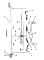
container 2 separated into afirst enclosure 50a and asecond enclosure 50b by aninterface 52. As shown bothenclosure bottom wall 4 withstirrer 20 secured thereon, aflat sheet grid 28a horizontally positioned at lower portion ofenclosure fluid port 6, respectively. Apump 54 is provided between the twofluid ports 6. Avacuum port 32 is provided at the upper portion ofenclosure impermeable barrier 34 is connected to thevacuum port 32 to stop microorganism from enteringenclosure vacuum port 32.Vacuum port 32 is also equipped with avalve 36 and asource 44 for generating pressure difference and providing vacuum. Preferably,source 44 is a vacuum pump for providing negative pressure or compressed air for providing positive pressure.Interface 52 has a controllable opening 56 (also referred as holder).Lumen device 46 is placed across opening 56 partly inenclosure 50a and partly inenclosure 50b.Opening 56 can be configured differently. For example, opening 56 can be made of ashutter 58 such as an iris diaphragm as shown in figure 3b, and the opening and closing of opening 56 can be controlled manually or automatically. In one embodiment, the blades of shutter 58 (eight blades are shown in figure 3b), can be divided into two groups. For example, each group contains four blades not next to each other. These two groups of blades are controlled separately by a controller so that while one group is in the close position holding the device to be sterilized the other group is in open position allowing the sterilant to sterilize the area occluded by the blades when the blades are in closed position. Another example ofshutter 58 is the Syntron Iris Flow Control Valve (by FMC Corporation) or the Iris diaphragm valves (Kemutec Inc.) as shown in figure 3c. Briefly,Iris valve 58a has acylindrical sleeve 90 with two retainingrings 92 located at two ends of thecylindrical sleeve 90.Sleeve 90 is made of Teflon or other suitable plastic or rubber material. When in use, a lumen device is inserted through anaperture 94 ofcylindrical sleeve 90. Afirst retaining ring 92 is secured and sealed to opening 56, asecond retaining ring 92 is free to rotate and coupled to interface 52 through a conventional mechanical mechanism (not shown) so that the turning of thesecond retaining ring 92 can be controlled mechanically or electronically fromoutside container 2. By rotating the retaining rings 92 relative to each other, the diameter ofaperture 94 of thecylindrical sleeve 90 can be increased or reduced, or totally shut off. If desirable, more than one shutter can be provided in theinterface 52. -
Opening 56 also can be a slot or a gap defined by twoplates 59 as shown in Figs. 3d and 3e. The contact edges or surfaces ofplate 59, which form the slot and hold thelumen device 46, are equipped with a layer ofexpandable material 60 such as silicon, or a layer ofcompressible material 62. The closing, and thus seal aroundlumen device 46, of the slot can be done either by movingplate 59 or expandingexpandable material 60. With a two-plate opening 56, more than one lumen device can be placed across theopening 56. When expandable or inflatable material is used onplate 59, an expansion fluid source can be provided to plate 59 to expand theexpandable material 60. In one embodiment, a layer ofcompressible material 62 is provided on top of the layer ofexpandable material 60 as shown in figure 3f. In another embodiment, theopening 56 is formed by anupper plate 59a and alower plate 59b as shown in figure 3g. Thelower plate 59b has a rectangular shape with a bottom edge and two side edges being secured and sealed to the bottom wall and two side walls ofcontainer 2, respectively. Theupper plate 59a also has a rectangular shape and its upper portion is movably inserted into ahousing 53a.Housing 53a forms the upper portion ofinterface 52. A portion ofhousing 53a extends along two side walls ofcontainer 2 to the upper edge (or contact surface) oflower plate 59b, forming tworails 53b for receiving the two side edges ofupper plate 59a and guiding the movement of theupper plate 59a. There provided a seal between theupper plate 59a and thehousing 53a andrail 53b. For example, an O-ring can be used inhousing 53a andrail 53b to seal theupper plate 59a. The upper edge of thelower plate 59b and the lower edge of theupper plate 59a are provided with a layer of compressible or expandable material. The movement of theupper plate 59a can be controlled by any suitable conventional method, mechanically or electrically, form the outside ofcontainer 2. Many different configurations and structures can be adopted for theopening 56. For example, the contact surface of opening 56 can be made of an uneven surface so that, when opening 56 is closed around a lumen device, the uneven surface will provide passage to allow both liquid and gas to pass therethrough while holding the lumen device. Thus, the occlusion area on the lumen device surface can be significantly reduced. The uneven surface may have textures, projections, sharp edges, or sharp points thereon. - In another embodiment, opening 56 is an aperture equipped with a layer of porous material or with a layer of expandable material and a layer of porous material on top of the expandable material.
Opening 56 also can be made of an aperture of suitable shape, such as cylindrical, lined with porous material. A shutter is secured to the aperture providing a steady holding of thelumen device 46 with minimal contact area or occlusion area. - Fig. 4 shows a
container 2 with an enclose 50 separated by aninterface 52. In this embodiment, thecontainer 2 with theenclosure 50 is placed inside and coupled tovacuum chamber 66.Vacuum chamber 66 has afirst vacuum port 68 which is in gas communication withcontainer 2 through a gas-permeable but microorganism-impermeable membrane 34 installed on the upper wall ofcontainer 2, and which is preferably located at the upper portion of a side wall ofvacuum chamber 66. Avalve 35 is provided abovemembrane 34 to control the opening and closing of gas communication ofcontainer 2 with outside throughmembrane 34.Vacuum chamber 66 also has asecond vacuum port 70 connecting to avacuum port 32 of theenclosure 50 through avalve 36. Preferably, thesecond vacuum port 70 also located at the upper portion of the side wall of the vacuum chamber and near thefirst vacuum port 68.Valve 36 is preferably located outside theenclosure 50 and inside thevacuum chamber 66. A detachable connector (not shown) is preferably provided betweenvalve 36 andsecond vacuum port 70 for attachingvalve 36 to and detachingvalve 36 from thesecond vacuum port 70. The first andsecond vacuum ports vacuum chamber 66. Avalve 72 is provided atfirst vacuum port 68 to control flow through thefirst vacuum port 68. Avalve 74 can also be provided at the common inlet of the first andsecond vacuum ports source 44 for generating pressure difference between the two ends of thelumen device 46 is provided at the common inlet of first andsecond vacuum ports source 44 is a vacuum pump for generating a negative pressure or compressed air for generating a positive pressure.Vacuum chamber 66 also has a firstfluid port 76 connecting to afluid port 6a of thecontainer 2 through avalve 8a, and a secondfluid port 78 connecting to afluid port 6b of theenclosure 50 through avalve 8b. The first andsecond fluid ports vacuum chamber 66 and close to each other. Thefluid port 6a is located at the lowest point of a slopedbottom wall 4a of thecontainer 2. In this embodiment, thefluid port 6a is located at one lower comer of thecontainer 2. Thefluid port 6b is located at the lowest point of a slopedbottom wall 4b of theenclosure 50. In this embodiment, thefluid port 6b is located at one lower corner of theenclosure 50. A detachable connector can be provided for connectingvalve fluid port vacuum chamber 66, first andsecond fluid ports valve 80. Aliquid pump 54 is also provided between the first andsecond fluid ports container 2 and theenclosure 50. Thecontainer 2 has alower grid 28a and anupper grid 28b. Preferably, thelower grid 28a and theupper grid 28b are a flat metal sheet and horizontally positioned at the lower and the upper portion of thecontainer 2, respectively.Stirrers 20 are located below thelower grid 28a.Interface 52 has an opening (or holder) 56 for holding alumen device 46. Theopening 56 can be configured in many different ways such as those described with Figs. 3b-3f. On the bottom wall ofvacuum chamber 66, a plurality oftransducer 16 is provided to generate ultrasonics. Accordingly, the space between outer surface of the bottom ofcontainer 2 and the inner surface of the bottom wall ofvacuum chamber 66 is filled with water or other suitable liquids providing a medium for the ultrasonics. - In using the apparatus with containers and enclosures separated by an interface in the cleaning/sterilizing or cleaning/disinfecting process of the present invention, a lumen device is placed into the
container 2 and theenclosure 50 across theinterface 52. Theopening 56 of theinterface 52 is then closed manually or automatically. Thus, opening 56 forms a seal around the lumen device. The extent of the sealing can be controlled through different degree of tightening of theopening 56 around thelumen device 46 for different purposes. As defined previously, three types of seal can be made between theopening 56 and thelumen device 46, gas-tight seal, loose-fitting seal and tight-fitting seal. If maximum pressure is intended a gas-tight seal should be used in this case thecontainer 2 is substantially totally sealed from theenclosure 50, neither gas nor liquid can flow through the space between theopening 56 and thelumen device 46. Under many situations such a gas-tight seal is not necessary. In this case, a tight-fitting seal can be used so that a portion of fluid in the system can flow or diffuse through the space between theopening 56 and thelumen device 46, but a large portion of the fluid flows through the lumen of thelumen device 46, and thelumen device 46 is still held in position by theopening 56 during agitation. Loose-fitting will provide a opportunity to clean/sterilize the outer surface area of thelumen device 46 which is otherwise obscured by theopening 56. - A cleaning solution is then introduced into the
container 2 and theenclosure 50 throughfluid port container 2 and theenclosure 50 is preferably not higher than the position of thevacuum port 32. A stirrer, a water jet or an air jet can be used to facilitate the cleaning of the outer surface of thelumen device 46. The cleaning solution is also circulated betweencontainer 2 andenclosure 50 through the lumen of thelumen device 46. There are at least two ways to make the circulation. One method is to apply vacuum to theenclosure 50 throughsecond vacuum port 70 ofvacuum chamber 66 andvacuum port 32 of theenclosure 50 while keepingvacuum chamber 66 andcontainer 2 at atmospheric pressure or any pressure higher than that of theenclosure 50. This can be done similarly whenvacuum chamber 66 is not used. The cleaning fluid then flows from thecontainer 2 into theenclosure 50 through thelumen device 46. Theliquid pump 54 circulates the cleaning fluid back to thecontainer 2. Theopening 56 and thestirrer 20 can be controlled by the electronic signals from the system. Air bubbles generated fromair pump 10 can be introduced at this stage to enhance the scrubbing action during cleaning. Thus, both the outer surface and the inner surface of thelumen device 46 can be cleaned at the same time. Vacuum can be applied tocontainer 2 to generate a pressure in thecontainer 2 lower than that of theenclosure 50. Forced air also can be used to push liquid through the lumen. If desired, the interior and the exterior of the lumen device can be cleaned separately. The cleaning fluid can be removed from thecontainer 2 andenclosure 50 through thefluid port bottom wall lumen device 46 can be removed either with vacuum or forced-air. - The rinsing with water and the treatment with liquid sterilant can be conducted similarly. When the treatment with a liquid sterilant is complete, the liquid sterilant is drained and a predetermined amount of the liquid sterilant can be retained in the wells. Then vacuum is applied to
chamber 66 andcontainer 2 either throughvacuum port container 2 to sterilize and dry the device simultaneously. A plasma can be used as an option to enhance the efficacy and/or to remove the sterilant residual. After the sterilization is completed, the chamber is vented and the container is ready to be retrieved from the chamber. If desired,valve 35 can be closed at any pressure below the atmospheric pressure and the sterilized device is kept incontainer 2 under a subatmospheric pressure. This may serve as an indication of a well maintained sterility, i.e. if the vacuum still exists when container is opened after a period of time of storage that indicates the sterility of the sterilized device is well kept. The pressure can be monitored and controlled by the pressure sensor on thevacuum chamber 66 or incontainer 2. - Figure 5a shows a container very similar to that shown in figure 3a except that two
holders 100 are used in opening 56 ofinterface 52. As shown in Figs. 5a and 5b, the twoholders 100 are secured to opening 56 alonglumen device 46 or the passage ofopening 56. Eachholder 100 is sealed to opening 56 in any suitable conventional manner and eachholder 100 is independently controllable.Holder 100 can be a shutter as the shutter described with Figures 3b and 3c, or made of two plates as described with figures 3d-3g. Figure 5b shows twoholders 100 of shutter type holding alumen device 46. During cleaning or sterilizing operation, afirst holder 100 is first closed and asecond holder 100 is opened, then the first holder is opened and thesecond holder 100 is closed. Thus,enclosures holder 100 with thedevice 46 and, in the meantime, the two contact surface areas of thedevice 46 occluded by the twoholders 100 are exposed alternately. - Figure 5c shows two
holders 100 of plate type holding alumen device 46. Each ofholders 100 can be constructed in the way as described previously with figures 3d-3g. Preferably, the gap (the opening for passing the lumen device) formed between the two plates of oneholder 100 forms an angle with that of theother holder 100 of the two holder structure. Preferably, the angle is 90 degree as shown in figure 5c. The twoholders 100 are preferably positioned close enough so that when theexpandable material 60 lined in the gap (opening) is expanded, theexpandable material 60 will also expand outwardly away from the two plates and become in contact with theother holder 100, thus help seal the gap of theother holder 100. This configuration provides an advantage that no complete seal is needed for a single holder, yet a good seal such as a gas-tight seal can be achieved when two such holders are combined. It has been noted by the applicants that, when a cylindrical lumen device is placed across the gap between the two plates ofholder 100, areas on the outer surface of the lumen device, where the diameter of the cylindrical lumen device is parallel to the gap, are more difficult to seal because theexpandable material 60 has to expand extra distance to cover those areas. By providing two closelypositioned holders 100 with the two gaps forming an angle, the above mentioned areas in each of the two holders can be sealed by the other holder. Therefore, the requirement to the expandable material can be lowered without sacrificing the sealing characteristics. - Figure 5d shows another embodiment of an interface of the present invention. In this embodiment, the
interface 52 containsmultiple openings 56c. Thisinterface 52 may have three parts. Afirst plate 59c has a plurality ofopenings 56c thereon. The cross section of theopening 56c as viewed from a direction perpendicular to the surface ofplate 59c has an elongate shape with its longitudinal axis extending along a substantially vertical direction. Other orientation also can be adopted. Preferably, opening 56c has a rectangular cross section. The upper side of theopenings 56c can be made open for easy access to a lumen device. The contact surface ofopening 56c is provided with a layer ofexpandable material 60. Asecond plate 59d is positioned beside thefirst plate 59c in parallel.Plate 59d can be secured and sealed to the bottom and side walls ofcontainer 2 with its upper edge or surface equipped with a layer ofexpandable material 60. Athird plate 59e is located above and aligned withsecond plate 59d. The third plate can be made a part of the lid forcontainer 2. The lower edge ofplate 59e and the upper edge ofplate 59d form a gap for passing a lumen device. The edges of the third plate is also provided with a layer of expandable or other sealingmaterial 60. Preferably, thesecond plate 59d and thethird plate 59e lie in one vertical plane, and thefirst plate 59c lies in another vertical plane parallel to that containingsecond plate 59d andthird plate 59e. Preferably, the gap formed betweenplate openings 56c, more preferably the angle is a right angle. In one preferred embodiment, the gap betweensecond plate 59d andthird plate 59e has a horizontal orientation, and theopenings 56c have a vertical orientation. The distance between thefirst plate 59c and the second andthird plate expandable material 60 on one plate is expanded, it will become in contact with the other plate to further facilitate seal around the lumen device passing both the gap betweenplate opening 56c ofplate 59c. Preferably, the dimension and the expandable material layer ofopening 56c is determined to allow theopening 56c to be closed and sealed when the expandable material is expanded even no lumen device is placed through the opening. - Figure 6 shows a
container 2 has threeenclosures Enclosure 50b is located in between and shares interfaces 52a and 52b withenclosure container 2 of figure 6 are similar to those of the container shown in figure 3a, and they are indicated by same numerical references. Twoopenings Opening lumen device 46 is placed across bothopening 56a andopening 56b with one end located inenclosure 50a and the other end inenclosure 50c. The advantage of the configuration is to help obtain a large pressure drop between the two ends of thedevice 46. Under certain circumstances, the seal between the opening and the lumen device may be not gas-tight, thus it is difficult to keep a large pressure drop at the two sides of the interface with such a seal. By adding oneintermediate enclosure 50b, the pressure drop across each interface 52a and 52b can be kept at a relative low level, yet the total pressure between the two ends of thedevice 46 or, in other words, betweenenclosure 50a andenclosure 50c can be still large enough to generate desired flow rate through the lumen of thelumen device 46. If desired, one interface 52a or 52b can be removed or opened, and in those cases thecontainer 2 can be operated just like that of figure 3a. - Figure 7a shows a
container 2 separated into anenclosure 50a and anenclosure 50b by aninterface 52 similar to the container of figure 3a except that atray 110 is placed acrossinterface 52 and located in bothenclosure 50a andenclosure 50b. Thetray 110 shown in figure 7a has a rectangular shape with four side walls perpendicular to a bottom wall defining a space for receiving alumen device 46. The side and bottom walls have open holes thereon. As shown in figure 7b,interface 52 can be configured to have two parts. The first part forms atray seat 112 extending along an interior periphery ofcontainer 2.Tray seat 112 has a first edge secured and sealed to the interior periphery ofcontainer 2 and asecond edge 114 shaped to receivetray 110.Edge 114 has a bottom portion and two side portions defining an open rectangular cross section. On top ofedge 114 is asealing layer 116 made of expandable, compressible, or other suitable material. Whentray 110 is placed intocontainer 2, an exterior periphery oftray 110 will seat onedge 114 andlayer 116. The second part ofinterface 52 can be aremovable plate 118 having anedge 120 shaped to fit the shape of an interior periphery oftray 110. On top ofedge 120 is asealing layer 122 made of expandable, compressible, or other suitable material.Plate 118 is inserted intotray 110 along an interior periphery oftray 110. A guide rail can be provided withtray 110 to guideplate 118 moving along an predetermined interior periphery. Different shapes can be used foredge 114 ofseat 112 and edge 120 ofplate 118, as long as the shape matches that of the exterior and interior periphery oftray 110. For example, in one embodiment, the open rectangular formed byedge 114 and edge 120 shown in figure 7b is modified by making the upper edge longer than the bottom edge of the open rectangular andtray 110 has a corresponding shape. This configuration makes it easier to theplate 118 down intotray 110 and seal it.Plate 118 can further include anopening 56 of any kind as discussed previously with figures 3b-3g.Opening 56 can be located inplate 118 or onedge 120 facing the bottom oftray 110 where lumen device is placed. In one embodiment, a layer of expandable, compressible, or other suitable sealing material is also provided withtray 110 along the interior periphery whereplate 118 is inserted. Figure 7c shows another embodiment in whichtray 110 has apartition 111 therein.Partition 111 can be made as part of thetray 110.Upper edge 111a ofpartition 111 has a layer of expandable, compressible, or other suitable sealing material.Partition 111 is aligned withplate 118 so that whenplate 118 is inserted intotray 110 seal can achieved betweenupper edge 111a ofpartition 111 and lower edge ofplate 118, and a lumen device can be placed through the gap or opening 56 formed betweenupper edge 111a ofpartition 111 and lower edge ofplate 118. In one embodiment, in the contact area betweentray 110 and interface 52 (orplate 112 and 118), a portion of side and bottom walls oftray 110 is removed so that in those portion thesealing layer 116 oftray seat 112 and thesealing layer 122 ofplate 118 of theinterface 52 are in direct contact.Plate 118 can be secured to a lid or cover 119 forcontainer 2 and, a portion of the lower surface of thecover 119 is provided with a layer of expandable, compressible, or other suitable sealing material to seal the upper edge of thetray 110 and thecontainer 2 as shown in figure 7c. - When exposed to a pressure difference between
enclosure tray 110 may be forced to move from high pressure side to low pressure side. In order to prevent this from happening, a stopper mechanism is provided. In one embodiment as shown in figures 8a-8d which are top views ofcontainer 2 andtray 110,tray 110 has arectangular bottom wall 130 with twoside walls 132 along two longer edges ofbottom wall 130 and twoside walls 134 along two shorter edges ofbottom wall 130. There is an indentation on eachside wall 132 extending along the entire height ofside wall 132 and substantially perpendicular tobottom wall 130.Container 2 also has arectangular bottom wall 140 with twoside walls 142 along the two longer edges ofbottom wall 140 and twoside walls 141 along two shorter edges ofbottom wall 140. There is aprojection 144 on eachside wall 142 extending along the entire height ofside wall 142 and perpendicular tobottom wall 140. The surface ofprojection 144 is covered with a layer of expandable, compressible, or othersuitable sealing material 146. Theprojection 144 has a shape matching that of theindentation 136. Whentray 110 is placed intocontainer 2,indentation 136 will engage withprojection 146 so as to holdtray 110 in position. Atray seat 112 with a layer of sealing material on its upper surface is provided onbottom wall 140 ofcontainer 2 extending between twoprojections 146.Tray 110 also has twoedges 137 on eachside wall 132 extending inwardly fromindentation 136. Aremovable plate 118 with a layer of sealing material on its contact edge is inserted intotray 110 through a rail defined by extrudingedge 137. In another embodiment, eachside wall 141 is provided with a stopper, such as an extrusion, to confine the movement oftray 110 along a direction perpendicular tointerface 52. - Figure 9 shows a recycling system which can be incorporated into any container systems used in the present invention. In this system, used liquid in a cleaning/sterilizing process is drained or pumped to a
reservoir 150 through afilter 152. Apump 154 can be provided betweenreservoir 150 andfluid port 6 to help drain the used liquid intoreservoir 150. The filtered liquid inreservoir 150 can be then cycled back tocontainer 2 through afluid port 6a. If necessary, filter 152 can be cleaned by back flash.Reservoir 150 is also equipped withseveral inlets 156 for water, cleaning chemical, and sterilant, respectively, and adrain 158. - The present invention has been described above. Many modifications and variation of the cleaning/sterilizing or cleaning/disinfecting process and the apparatus in such process may be made without departing substantially from the spirit and scope of the present invention. Accordingly, it should be clearly understood that the form of the invention described and illustrated herein is exemplary only, and is not intended as a limitation on the scope.
Claims (30)
- A method for cleaning/sterilizing or cleaning/disinfecting a device having a lumen with at least two open ends comprising the steps of:a) providing a container having at least one enclosure and at least one interface separating said enclosure from said container, said interface having at least one opening thereon;b) placing said device across said opening with one open end in said container and another open end in said enclosure;c) generating a flow of a cleaning solution through said lumen to clean the inner surface of said lumen;d) generating a flow of rinse solution through said lumen to rinse the inner surface of said lumen;e) treating said device with a chemical germicide; andf) adjusting said opening in any of steps c) to e) to reduce areas on outer surface of said device which are occluded from exposure to the cleaning solution, the rinse solution, or the chemical germicide by contacting with the opening, or to expose said areas to the cleaning solution, the rinse solution or the chemical germicide.
- A method of claim 1, wherein one or more steps are repeated.
- A method of claim 1 or 2, wherein along its passage, said opening has at least two independently controllable apertures for holding and sealing said device.
- A method of claim 3, wherein the step of adjusting said opening comprises opening one of said two apertures while closing the other aperture so that the areas on the outer surface of said device occluded by the two apertures are alternately exposed to the cleaning solution, the rinse solution, or the chemical germicide in step c), d), or e), respectively.
- A method of any preceding claim, further comprising retaining a predetermined amount of said chemical germicide in said container and enclosure and vaporizing the retained chemical germicide to sterilize (or disinfect) and dry said device under vacuum during or after step e).
- A method of claim 5, wherein the sterilizing or disinfecting is conducted under a diffusion restricted environment.
- A method of claim 5, wherein the sterilizing or disinfecting is conducted by reducing pressure to a first predetermined pressure followed by further reducing said first pressure to a predetermined second pressure.
- A method of claim 5, wherein the sterilizing or disinfecting is conducted at controlled pump down rate.
- A method of any of claims 5 to 8, wherein the sterility of said device is maintained in the container and enclosure after said device is sterilized and dried.
- A method of any of claims 5 to 9, further comprising removably attaching said container to a vacuum system for applying vacuum to said container or enclosure and detaching said container after the device is sterilized (or disinfected) and dried.
- A method of any preceding claim, wherein the flow through said lumen is generated by applying a pressure higher than atmospheric pressure at one end of said lumen, or by applying vacuum to one end of said lumen device.
- A method of any preceding claim, further comprising treating a non-lumen device in said container or enclosure.
- A method of any preceding claim, wherein said opening has separately controllable and moveable contact points, and the adjusting step comprises controlling said contact points so that a different portion of said contact points is made in contact with the device alternately.
- A method of any preceding claim, wherein the opening forms a seal around said device selected from the group consisting of a gas-tight seal, a tight-fitting seal, or a loose-fitting seal.
- An apparatus for cleaning/sterilizing or cleaning/disinfecting a lumen device having at least two open ends comprising:a container having a fluid port for flowing and draining a fluid in and out said container;at least one enclosure coupled with said container for receiving part of said lumen device so that one end of said lumen device is located in said enclosure and the other end of said lumen device is located in said container;an interface separating said container and enclosure, said interface having at least one opening;at least one openable and closeable holder sealably coupled to said opening;a source for creating a pressure difference between said two open ends to generate a flow through the lumen of said lumen device;a cleaning mechanism adapted to clean said device in said container or said enclosure.
- An apparatus of claim 15, wherein said interface is removable.
- An apparatus of claim 15 or 16, wherein said holder is a shutter.
- An apparatus of claim 15 or 16, wherein said holder is equipped with expandable material on its contact surface with said device.
- An apparatus of claim 15 or 16, wherein said holder is equipped with compressible material on its contact surface with said device.
- An apparatus of claim 15 or 16, wherein said holder has two plates forming a gap therebetween for passing said device, the surfaces of the plates facing the gap are equipped with expandable or compressible material.
- An apparatus of any of claims 15 to 20, wherein two independently controllable holders are sealably arranged along the passage of one opening.
- An apparatus of claim 21, wherein each one of the two holders comprises two plates forming a gap therebetween for passing said device, the surfaces of the plates facing the gap are equipped with expandable or compressible material.
- An apparatus of claim 22, wherein each of said gaps defines an elongate cross section having a longitudinal axis as viewed from a direction perpendicular to the surface of the plates, the longitudinal axis of one said gap forms an angle with that of the other gap, and said two holders are placed close enough to each other for said expandable material on one holder to be brought in contact with the other holder when the expandable material is expanded.
- An apparatus of any of claims 15 to 23, wherein said holder comprises a shutter.
- An apparatus of any of claims 15 to 24, wherein said apparatus further comprises a vacuum system, said container comprises a gas-permeable and microorganism-impermeable barrier and is detachably coupled to said vacuum system.
- An apparatus of claim 25, wherein said gas-permeable and microorganism-impermeable barrier is equipped with a valve for opening and closing gas communication between the container and the vacuum system or between the container and atmosphere through said barrier.
- An apparatus of any of claims 15 to 26, wherein said cleaning mechanism is selected from the group consisting of a stirrer, a liquid jet, an air jet, ultrasonics, or a bubble generator.
- An apparatus of any of claims 15 to 27, wherein said interface comprises a first plate having a plurality of openings with elongate cross section, and at least two other plates forming a gap along a longitudinal direction, said plates are configured so that the longitudinal direction of the gap and the longitudinal direction of the elongate cross section of the opening form a substantially right angle.
- An apparatus of any of claims 15 to 28, wherein said container has a first enclosure sharing with the container a first interface having a first opening and a second enclosure sharing with the first enclosure a second interface having a second opening, wherein the device is placed across the first and second interface through the first and second opening so that one open end of the device is located in the container and the other open end of the device is located in the second enclosure.
- An apparatus of any of claims 15 to 29, wherein said holder has a plurality of contact points on its inner surface for holding the device, said contact points being separately controllable and moveable.
Applications Claiming Priority (2)
| Application Number | Priority Date | Filing Date | Title |
|---|---|---|---|
| US08/992,602 US6013227A (en) | 1997-12-17 | 1997-12-17 | Lumen device reprocessor without occlusion |
| US992602 | 1997-12-17 |
Publications (3)
| Publication Number | Publication Date |
|---|---|
| EP0923951A2 true EP0923951A2 (en) | 1999-06-23 |
| EP0923951A3 EP0923951A3 (en) | 1999-06-30 |
| EP0923951B1 EP0923951B1 (en) | 2003-10-01 |
Family
ID=25538519
Family Applications (1)
| Application Number | Title | Priority Date | Filing Date |
|---|---|---|---|
| EP98310360A Expired - Lifetime EP0923951B1 (en) | 1997-12-17 | 1998-12-17 | Container for cleaning or sterilizing lumen devices |
Country Status (10)
| Country | Link |
|---|---|
| US (2) | US6013227A (en) |
| EP (1) | EP0923951B1 (en) |
| JP (2) | JPH11277005A (en) |
| CN (1) | CN1243571C (en) |
| AU (2) | AU733540B2 (en) |
| BR (1) | BR9805420A (en) |
| CA (1) | CA2256036C (en) |
| DE (2) | DE19882908T1 (en) |
| ES (1) | ES2209074T3 (en) |
| WO (1) | WO1999030748A1 (en) |
Cited By (13)
| Publication number | Priority date | Publication date | Assignee | Title |
|---|---|---|---|---|
| EP1016371A1 (en) * | 1998-12-30 | 2000-07-05 | Ethicon, Inc. | Method for cleaning and sterilizing lumen devices |
| EP1110557A2 (en) * | 1999-12-22 | 2001-06-27 | Ethicon, Inc. | Method for sterilizing devices in a container |
| EP1186307A2 (en) * | 2000-08-30 | 2002-03-13 | Ethicon, Inc. | Method and apparatus for processing device with fluid submersion |
| US6685895B1 (en) | 1997-12-17 | 2004-02-03 | Ethicon, Inc. | Method and apparatus for processing device with reduced occlusion |
| US7300637B2 (en) | 2002-09-30 | 2007-11-27 | Ethicon, Inc. | Sterilization container kit |
| WO2012007470A1 (en) * | 2010-07-15 | 2012-01-19 | Betek Gmbh & Co. Kg | Soil working tool |
| ITCO20110009A1 (en) * | 2011-03-16 | 2012-09-17 | Soltec S R L | METHOD OF DRYING OF SURGICAL INSTRUMENTS AND APPLIANCE THAT IMPLEMENTS IT |
| ITCO20110008A1 (en) * | 2011-03-16 | 2012-09-17 | Soltec S R L | RINSING METHOD OF SURGICAL INSTRUMENTS AND APPLIANCE THAT IMPLEMENTS IT |
| WO2014183805A1 (en) * | 2013-05-17 | 2014-11-20 | Partners For Endoscopy Limited | A method for the decontamination of medical instruments |
| CN107823662A (en) * | 2017-12-06 | 2018-03-23 | 衡阳博思科技有限公司 | A kind of instruments used for education chlorination equipment |
| CN108244448A (en) * | 2017-12-15 | 2018-07-06 | 安徽恋尚你食品有限公司 | A kind of frozen dried food processes raw material cleaning and sterilization equipment integrating and application method |
| US10022189B2 (en) | 2013-12-16 | 2018-07-17 | Stryker Sustainability Solutions, Inc. | Apparatus and method for cleaning an instrument |
| CN112535756A (en) * | 2020-11-05 | 2021-03-23 | 珠海格力电器股份有限公司 | Sterilizing equipment control method, device and system and sterilizing equipment |
Families Citing this family (73)
| Publication number | Priority date | Publication date | Assignee | Title |
|---|---|---|---|---|
| US6325972B1 (en) * | 1998-12-30 | 2001-12-04 | Ethicon, Inc. | Apparatus and process for concentrating a liquid sterilant and sterilizing articles therewith |
| US6815206B2 (en) * | 1997-09-19 | 2004-11-09 | Ethicon, Inc. | Container monitoring system |
| US6013227A (en) * | 1997-12-17 | 2000-01-11 | Johnson & Johnson Medical, Inc. | Lumen device reprocessor without occlusion |
| US6596232B1 (en) | 1997-12-17 | 2003-07-22 | Ethicon, Inc. | Device processing apparatus and method having positive pressure with two partitions to minimize leakage |
| US6312646B2 (en) | 1998-08-17 | 2001-11-06 | Enviromedical Systems, Inc. | Sterilization of elongate lumens |
| US6582654B1 (en) | 2000-02-07 | 2003-06-24 | Steris Inc. | Fluid spray system for cleaning and sterilizing medical devices supported on a rack |
| US6656423B1 (en) | 2000-02-07 | 2003-12-02 | Steris Inc. | Sterile water generator |
| US6814932B2 (en) * | 2000-03-31 | 2004-11-09 | Steris Inc. | Device support activation system |
| WO2002041926A1 (en) * | 2000-11-27 | 2002-05-30 | Enviromedical Systems, Inc. | Sterilization of elongate lumens |
| AU2001245092A1 (en) * | 2000-11-29 | 2002-06-11 | Enviromedical Systems, Inc. | Sterilization of elongate lumens |
| US6919057B2 (en) * | 2002-04-04 | 2005-07-19 | Steris Inc. | Automated endoscope reprocessor |
| US7351386B2 (en) | 2002-04-04 | 2008-04-01 | Steris Inc | Cartridge holder for automated reprocessor |
| US20040016706A1 (en) * | 2002-07-29 | 2004-01-29 | Minnix Charles M. | Ozone purification system for water |
| US8764989B2 (en) * | 2002-07-29 | 2014-07-01 | Charles M. Minnix | Ozone purification system for water |
| WO2005003273A1 (en) * | 2003-07-01 | 2005-01-13 | William A. Barnstead Engineering Corporation | Method, process, chemistry and apparatus for treating a substrate |
| WO2005062914A2 (en) * | 2003-12-22 | 2005-07-14 | Institute For Environmental Health, Inc. | Microbial sampling device |
| BRPI0400237A (en) | 2004-01-16 | 2005-08-16 | Tadashi Shiosawa | Vacuum sterilization process with steam application of a mixture of peracetic acid with hydrogen peroxide and atmospheric air residual gas plasma excited by pulsed electric discharge; devices and operating methods used in the sterilization process |
| SE527020C2 (en) * | 2004-04-27 | 2005-12-06 | Getinge Disinfection Ab | Disinfection equipment with pump device |
| JP2006081829A (en) * | 2004-09-17 | 2006-03-30 | Hk Planning:Kk | Cleaning apparatus and method for surgical instrument |
| JP2006081831A (en) * | 2004-09-17 | 2006-03-30 | Hk Planning:Kk | Cleaning apparatus and method for surgical instrument |
| JP2006081830A (en) * | 2004-09-17 | 2006-03-30 | Hk Planning:Kk | Cleaning apparatus for surgical instrument and liquid draining method |
| US20060269442A1 (en) * | 2005-05-31 | 2006-11-30 | Nguyen Nick N | Endoscope reprocessor connectors having reduced occlusion |
| WO2007030625A2 (en) * | 2005-09-07 | 2007-03-15 | Pearl Technologies, L.L.C. | Air driven hard surface cleaning tool |
| US8579807B2 (en) | 2008-04-28 | 2013-11-12 | Ethicon Endo-Surgery, Inc. | Absorbing fluids in a surgical access device |
| US8690831B2 (en) | 2008-04-25 | 2014-04-08 | Ethicon Endo-Surgery, Inc. | Gas jet fluid removal in a trocar |
| DE102007009936B4 (en) | 2007-03-01 | 2011-02-03 | Rainer Hoen | Cleaning device for compressed air breathing apparatus |
| US8100929B2 (en) | 2007-06-29 | 2012-01-24 | Ethicon Endo-Surgery, Inc. | Duckbill seal with fluid drainage feature |
| US8510902B2 (en) | 2007-12-03 | 2013-08-20 | Dri-Eaz Products, Inc. | Air induction hard surface cleaning tool with an internal baffle |
| US7976501B2 (en) | 2007-12-07 | 2011-07-12 | Ethicon Endo-Surgery, Inc. | Trocar seal with reduced contact area |
| US9358041B2 (en) | 2008-04-28 | 2016-06-07 | Ethicon Endo-Surgery, Llc | Wicking fluid management in a surgical access device |
| US8636686B2 (en) | 2008-04-28 | 2014-01-28 | Ethicon Endo-Surgery, Inc. | Surgical access device |
| US8568362B2 (en) | 2008-04-28 | 2013-10-29 | Ethicon Endo-Surgery, Inc. | Surgical access device with sorbents |
| US11235111B2 (en) | 2008-04-28 | 2022-02-01 | Ethicon Llc | Surgical access device |
| US8273060B2 (en) | 2008-04-28 | 2012-09-25 | Ethicon Endo-Surgery, Inc. | Fluid removal in a surgical access device |
| US8870747B2 (en) | 2008-04-28 | 2014-10-28 | Ethicon Endo-Surgery, Inc. | Scraping fluid removal in a surgical access device |
| USD700326S1 (en) | 2008-04-28 | 2014-02-25 | Ethicon Endo-Surgery, Inc. | Trocar housing |
| US20090270686A1 (en) * | 2008-04-29 | 2009-10-29 | Ethicon Endo-Surgery, Inc. | Methods and devices for maintaining visibility during surgical procedures |
| US7981092B2 (en) | 2008-05-08 | 2011-07-19 | Ethicon Endo-Surgery, Inc. | Vibratory trocar |
| US9166139B2 (en) * | 2009-05-14 | 2015-10-20 | The Neothermal Energy Company | Method for thermally cycling an object including a polarizable material |
| WO2011047127A1 (en) | 2009-10-15 | 2011-04-21 | Minntech Corporation | Room fogging disinfection system |
| US8821807B2 (en) | 2009-12-03 | 2014-09-02 | Medivators Inc. | Container and system for decontaminating a medical device with a fog |
| GB2483741A (en) * | 2010-09-15 | 2012-03-21 | Medicart Int Ltd | Conditioning medical equipment |
| US9017607B2 (en) | 2011-05-27 | 2015-04-28 | Medivators Inc. | Decontamination system including environmental control using a decontaminating substance |
| DE102011114899A1 (en) | 2011-10-05 | 2013-04-11 | Michael Markus Heckmann | Household appliance for disinfecting and drying |
| US8920574B2 (en) * | 2011-10-21 | 2014-12-30 | Ethicon, Inc. | Instrument reprocessor and instrument reprocessing methods |
| GB2500866A (en) * | 2012-02-08 | 2013-10-09 | Partners For Endoscopy Ltd | Method for decontamination of medical instruments |
| CN102909193A (en) * | 2012-11-13 | 2013-02-06 | 宁夏电力公司电力科学研究院 | Direct washing filter ultrasonic cleaning device |
| US9179812B2 (en) | 2012-11-19 | 2015-11-10 | Sapphire Scientific Inc. | Hard surface cleaners having cleaning heads with rotational assist, and associated systems, apparatuses and methods |
| FI20135362A (en) * | 2013-04-12 | 2014-10-13 | Vahterus Oy | Procedure for cleaning a plate heat exchanger and plate heat exchanger |
| US10022031B2 (en) | 2013-11-15 | 2018-07-17 | Dri-Eaz Products, Inc. | Power/water supply and reclamation tank for cleaning devices, and associated systems and methods |
| US10584497B2 (en) | 2014-12-05 | 2020-03-10 | Dri-Eaz Products, Inc. | Roof cleaning processes and associated systems |
| CN104707821B (en) * | 2015-03-18 | 2017-01-25 | 郑州大学第一附属医院 | Energy-saving type medical equipment cleaning and sterilization device |
| US10279060B2 (en) | 2015-04-28 | 2019-05-07 | Medivators Inc. | System for decontamination of a lumen device |
| US10264939B2 (en) | 2015-08-17 | 2019-04-23 | Skagit Northwest Holdings, Inc. | Rotary surface cleaning tool |
| WO2018090133A1 (en) | 2016-11-15 | 2018-05-24 | Ideate Medical | Apparatus and method for sterilization of an article |
| CN110167459B (en) * | 2016-12-21 | 2022-08-09 | 爱惜康有限责任公司 | Surgical instrument with primary and safety processors |
| US20200054775A1 (en) * | 2017-03-07 | 2020-02-20 | Medivators Inc. | Valved chamber for lumen device and methods of using the same |
| CN107899043B (en) * | 2017-11-25 | 2022-02-15 | 温州医科大学附属第一医院 | Medical instrument storage and cleaning device |
| CN108853539A (en) * | 2018-02-23 | 2018-11-23 | 连云港佑源医药设备制造有限公司 | A kind of low temperature plasma ozone sterilizer and sterilizing methods |
| CN108588850B (en) * | 2018-04-18 | 2019-11-19 | 重庆市亿柘农业开发有限公司 | A kind of animal husbandry wool cleaning device squeezing cleaning technique based on vortex |
| CN108570714B (en) * | 2018-04-18 | 2019-12-03 | 安徽省卓创信息科技服务有限公司 | A kind of wool cleaning device of the animal husbandry based on bubbling -cleaning technology |
| CN110859486B (en) * | 2018-08-27 | 2023-04-18 | 佛山市顺德区美的电热电器制造有限公司 | Vacuum cooking appliance and method for identifying cooking amount in vacuum cooking appliance |
| CN108941036A (en) * | 2018-09-21 | 2018-12-07 | 吕英清 | A kind of medical nursing disinfection cleaning device |
| IT201900010914A1 (en) * | 2019-07-04 | 2021-01-04 | Illycaffe Spa | COFFEE BEVERAGE DISPENSING ASSEMBLY AND RELATED DISPENSING MACHINE |
| CN110584705B (en) * | 2019-10-11 | 2022-02-22 | 吴国超 | Four-dimensional color ultrasonic machine |
| CN110812513A (en) * | 2019-11-14 | 2020-02-21 | 刘金友 | Medical supplies disinfecting equipment |
| CN112344116B (en) * | 2020-10-10 | 2022-07-29 | 金汝 | Cleanable pipeline |
| CN112891583A (en) * | 2021-01-18 | 2021-06-04 | 吉林大学 | Sterilizing device for operating room anaesthetists used before and after operation |
| CN113275297B (en) * | 2021-05-15 | 2023-01-03 | 天祝臣祥菌业科技有限公司 | Edible mushroom production and purification device and using method thereof |
| CN113458066B (en) * | 2021-07-09 | 2024-03-15 | 河南省农业科学院畜牧兽医研究所 | Cleaning and sterilizing device for bovine embryo transplanting gun assembly |
| CN113520287B (en) * | 2021-07-21 | 2022-07-19 | 淮安市第二人民医院 | Intelligent cleaning system for hard endoscope in gastroenterology department |
| CN114308835B (en) * | 2022-01-05 | 2022-12-16 | 张卫英 | Instrument cleaning device for obstetrics and gynecology department |
| CN116320289B (en) * | 2023-01-31 | 2023-10-31 | 宇超电力股份有限公司 | Intelligent comprehensive monitoring device for power distribution room environment and application method thereof |
Citations (5)
| Publication number | Priority date | Publication date | Assignee | Title |
|---|---|---|---|---|
| US4380530A (en) * | 1981-02-13 | 1983-04-19 | Ben Venue Laboratories, Inc. | Sterilizer with inflatable article holder |
| JPS63302817A (en) * | 1987-06-03 | 1988-12-09 | Olympus Optical Co Ltd | Washing and disinfecting apparatus for endoscope |
| US5443801A (en) * | 1990-07-20 | 1995-08-22 | Kew Import/Export Inc. | Endoscope cleaner/sterilizer |
| US5641464A (en) * | 1995-12-01 | 1997-06-24 | B & B Medical Technologies, Inc. | Stethoscope cleansing device and method |
| WO1997024147A1 (en) * | 1996-01-02 | 1997-07-10 | Kew Import/Export Inc. | Medical cleaning and sterilizing apparatus |
Family Cites Families (58)
| Publication number | Priority date | Publication date | Assignee | Title |
|---|---|---|---|---|
| US3893843A (en) * | 1970-06-24 | 1975-07-08 | Arbrook Inc | Method for washing and disinfecting hollow, flexible articles |
| US3814901A (en) * | 1973-05-07 | 1974-06-04 | Lincoln Mfg Co | Steam heating device |
| US4203943A (en) * | 1977-11-11 | 1980-05-20 | American Sterilizer Company | Method of biocidal sterilization using cyclic subatmospheric pressure conditioning |
| US4321232B1 (en) * | 1980-03-25 | 1997-12-09 | Abtox Inc | Package and sterilizing process for same |
| US4337223A (en) * | 1981-02-13 | 1982-06-29 | Ben Venue Laboratories, Inc. | Sterilizing apparatus incorporating recirculation of chamber atmosphere |
| US4410492A (en) * | 1981-02-13 | 1983-10-18 | Ben Venue Laboratories, Inc. | Sterilizing method incorporating recirculation of chamber atmosphere |
| US4579597A (en) * | 1983-05-02 | 1986-04-01 | Olympus Optical Co., Ltd. | Method of cleaning endoscope channels |
| SE450685B (en) * | 1983-09-23 | 1987-07-20 | Electrolux Ab | PROCEDURE AND DEVICE FOR HEAT TREATMENT OF GOODS |
| GB8427999D0 (en) * | 1983-11-07 | 1984-12-12 | American Sterilizer Co | Vaporization method |
| DE3416743A1 (en) * | 1984-01-13 | 1985-07-25 | Wolfgang 4010 Hilden Griesat | Disinfector for medical apparatus having channels to be disinfected, especially endoscopes |
| US4756882A (en) * | 1985-06-21 | 1988-07-12 | Surgikos Inc. | Hydrogen peroxide plasma sterilization system |
| US5077008A (en) * | 1986-02-06 | 1991-12-31 | Steris Corporation | Anti-microbial composition |
| US5391360A (en) * | 1986-02-06 | 1995-02-21 | Steris Corporation | Overcenter, cam driven locking mechanism |
| US5407685A (en) * | 1986-02-06 | 1995-04-18 | Steris Corporation | Controlled oxygen/anti-microbial release films |
| US5209909A (en) * | 1986-02-06 | 1993-05-11 | Steris Corporation | Two compartment cup for powdered sterilant reagent components |
| US5217698A (en) * | 1986-02-06 | 1993-06-08 | Steris Corporation | Office size instrument sterilization system |
| US5037623A (en) * | 1986-02-06 | 1991-08-06 | Steris Corporation | Sterilant concentrate injection system |
| US5374394A (en) * | 1986-02-06 | 1994-12-20 | Steris Corporation | Medical waste decontamination |
| US5116575A (en) * | 1986-02-06 | 1992-05-26 | Steris Corporation | Powdered anti-microbial composition |
| US5225160A (en) * | 1986-02-06 | 1993-07-06 | Steris Corporation | Medical instrument decontamination and sterilization processor |
| US5552115A (en) * | 1986-02-06 | 1996-09-03 | Steris Corporation | Microbial decontamination system with components porous to anti-microbial fluids |
| US4731222A (en) * | 1986-02-06 | 1988-03-15 | Innovative Medical Technologies | Automated liquid sterilization system |
| US5350563A (en) * | 1986-02-06 | 1994-09-27 | Steris Corporation | Cold sterilant with extended active life |
| US4943414A (en) * | 1987-07-30 | 1990-07-24 | Johnson & Johnson Medical, Inc. | Method for vapor sterilizaton of articles having lumens |
| US5580530A (en) * | 1987-07-30 | 1996-12-03 | Johnson & Johnson Medical, Inc. | Device for vapor sterilization of articles having lumens |
| US4956145A (en) * | 1987-12-30 | 1990-09-11 | American Sterilizer Company | Optimum hydrogen peroxide vapor sterilization method |
| US4937046A (en) * | 1988-01-26 | 1990-06-26 | H. W. Andersen Products Inc. | Sterilization system and method |
| US5186893A (en) * | 1989-03-08 | 1993-02-16 | Abtox, Inc. | Plasma cycling sterilizing process |
| JPH03111026A (en) * | 1989-09-26 | 1991-05-10 | Olympus Optical Co Ltd | Device for cleaning and disinfecting endoscope |
| US5244629A (en) * | 1990-08-31 | 1993-09-14 | Caputo Ross A | Plasma sterilizing process with pulsed antimicrobial agent pretreatment |
| US5017241A (en) * | 1990-10-16 | 1991-05-21 | The Graver Company | Backwash method and apparatus |
| US5114596A (en) * | 1990-10-16 | 1992-05-19 | The Graver Company | Backwash method and apparatus |
| US5279799A (en) * | 1990-10-23 | 1994-01-18 | Hamo Ag | Apparatus for cleaning and testing endoscopes |
| JPH0584281A (en) * | 1991-09-25 | 1993-04-06 | Kawasumi Lab Inc | High-pressure steam sterilization method for medical treatment container |
| US5310524A (en) * | 1992-02-11 | 1994-05-10 | Minntech Corporation | Catheter reprocessing and sterilizing system |
| US5445792A (en) * | 1992-03-13 | 1995-08-29 | American Sterilizer Company | Optimum hydrogen peroxide vapor sterlization method |
| EP0584338A1 (en) * | 1992-03-13 | 1994-03-02 | American Sterilizer Company | Device and system for sterilizing objects |
| EP0583465A1 (en) * | 1992-03-13 | 1994-02-23 | American Sterilizer Company | Sterilization apparatus and method for multicomponent sterilant |
| US5260021A (en) * | 1992-06-29 | 1993-11-09 | Allergan, Inc. | Hydrogen peroxide-containing gels and contact lens disinfecting using same |
| US5266275A (en) * | 1992-09-04 | 1993-11-30 | Faddis Chris G | Ozone sterilization system secondary safety chamber |
| US5380369A (en) * | 1992-10-22 | 1995-01-10 | Kaltenbach & Voigt Gmbh & Co. | Process for cleaning and/or disinfecting and/or maintaining medical or dental instruments |
| US5527508A (en) * | 1992-11-12 | 1996-06-18 | American Sterilizer Company | Method of enhanced penetration of low vapor pressure chemical vapor sterilants during sterilization |
| EP0603563A1 (en) * | 1992-12-04 | 1994-06-29 | F. Gehrig + Co. Ag | Method and apparatus for testing and cleaning endoscopes |
| JP3286044B2 (en) * | 1993-01-26 | 2002-05-27 | オリンパス光学工業株式会社 | Endoscope cleaning and disinfecting equipment |
| US5348711A (en) * | 1993-07-21 | 1994-09-20 | Mdt Corporation | Dental handpiece sterilizer |
| FR2707896B1 (en) * | 1993-07-22 | 1995-09-01 | Chemoxal Sa | Process for treating an article and new aqueous solution of hydrogen peroxide. |
| US5407648A (en) * | 1993-09-29 | 1995-04-18 | Paragon Group Of Plastics Companies, Inc. | Combination sterilization tray and mat |
| JPH07299125A (en) * | 1994-04-29 | 1995-11-14 | Yoshida Dental Mfg Co Ltd | High pressure steam sterilizer |
| US5441707A (en) * | 1994-10-03 | 1995-08-15 | Paragon Group Of Plastics Companies, Inc. | Sterilization container |
| DE4440363C2 (en) * | 1994-11-11 | 1997-10-02 | Netzsch Newamatic Gmbh | Procedure for testing and cleaning instruments for minimally invasive surgery or minimally invasive examination of body cavities |
| US5540221A (en) * | 1994-11-17 | 1996-07-30 | Respironics, Inc. | Resuscitator |
| US5492671A (en) * | 1994-12-20 | 1996-02-20 | Zimmer, Inc. | Sterilization case and method of sterilization |
| US5599512A (en) * | 1995-05-10 | 1997-02-04 | Poly Vac, Incorporated | Sterilization support and storage container system |
| US5753195A (en) * | 1996-01-02 | 1998-05-19 | Kew Import/Export Inc. | Cleaning and sterilizing mechanism |
| US6030579A (en) * | 1996-04-04 | 2000-02-29 | Johnson & Johnson Medical, Inc. | Method of sterilization using pretreatment with hydrogen peroxide |
| US5851485A (en) * | 1996-12-20 | 1998-12-22 | Johnson & Johnson Medical, Inc. | Process for sterilization with liquid sterilant using controlled pumpdown rate |
| US5871692A (en) * | 1997-01-14 | 1999-02-16 | Steris Corporation | Method and apparatus for cleaning, decontaminating, and sterilizing catheters |
| US6013227A (en) * | 1997-12-17 | 2000-01-11 | Johnson & Johnson Medical, Inc. | Lumen device reprocessor without occlusion |
-
1997
- 1997-12-17 US US08/992,602 patent/US6013227A/en not_active Expired - Lifetime
-
1998
- 1998-12-15 CA CA002256036A patent/CA2256036C/en not_active Expired - Fee Related
- 1998-12-16 DE DE19882908T patent/DE19882908T1/en not_active Withdrawn
- 1998-12-16 WO PCT/US1998/026779 patent/WO1999030748A1/en active Application Filing
- 1998-12-16 JP JP10375660A patent/JPH11277005A/en not_active Ceased
- 1998-12-16 AU AU97144/98A patent/AU733540B2/en not_active Ceased
- 1998-12-16 JP JP2000538726A patent/JP2002508219A/en active Pending
- 1998-12-16 AU AU19216/99A patent/AU1921699A/en not_active Abandoned
- 1998-12-17 BR BR9805420-1A patent/BR9805420A/en not_active Application Discontinuation
- 1998-12-17 CN CN98127186.3A patent/CN1243571C/en not_active Expired - Fee Related
- 1998-12-17 DE DE69818617T patent/DE69818617T2/en not_active Expired - Lifetime
- 1998-12-17 EP EP98310360A patent/EP0923951B1/en not_active Expired - Lifetime
- 1998-12-17 ES ES98310360T patent/ES2209074T3/en not_active Expired - Lifetime
- 1998-12-30 US US09/222,860 patent/US6423266B1/en not_active Expired - Lifetime
Patent Citations (5)
| Publication number | Priority date | Publication date | Assignee | Title |
|---|---|---|---|---|
| US4380530A (en) * | 1981-02-13 | 1983-04-19 | Ben Venue Laboratories, Inc. | Sterilizer with inflatable article holder |
| JPS63302817A (en) * | 1987-06-03 | 1988-12-09 | Olympus Optical Co Ltd | Washing and disinfecting apparatus for endoscope |
| US5443801A (en) * | 1990-07-20 | 1995-08-22 | Kew Import/Export Inc. | Endoscope cleaner/sterilizer |
| US5641464A (en) * | 1995-12-01 | 1997-06-24 | B & B Medical Technologies, Inc. | Stethoscope cleansing device and method |
| WO1997024147A1 (en) * | 1996-01-02 | 1997-07-10 | Kew Import/Export Inc. | Medical cleaning and sterilizing apparatus |
Non-Patent Citations (1)
| Title |
|---|
| PATENT ABSTRACTS OF JAPAN vol. 013, no. 137 (C-582), 5 April 1989 & JP 63 302817 A (OLYMPUS OPTICAL CO LTD), 9 December 1988 * |
Cited By (22)
| Publication number | Priority date | Publication date | Assignee | Title |
|---|---|---|---|---|
| US7179419B2 (en) | 1996-04-04 | 2007-02-20 | Johnson & Johnson Medical Div Ethicon, Inc. | Method for sterilizing devices in a container |
| US6645430B1 (en) | 1997-12-17 | 2003-11-11 | Ethicon, Inc. | Method and apparatus for processing device with fluid submersion |
| US6685895B1 (en) | 1997-12-17 | 2004-02-03 | Ethicon, Inc. | Method and apparatus for processing device with reduced occlusion |
| EP1016371A1 (en) * | 1998-12-30 | 2000-07-05 | Ethicon, Inc. | Method for cleaning and sterilizing lumen devices |
| US6534002B1 (en) | 1998-12-30 | 2003-03-18 | Ethicon, Inc. | Flow of fluid through a lumen device from smaller-caliber end to larger-caliber end |
| EP1110557A2 (en) * | 1999-12-22 | 2001-06-27 | Ethicon, Inc. | Method for sterilizing devices in a container |
| EP1110557A3 (en) * | 1999-12-22 | 2003-04-23 | Ethicon, Inc. | Method for sterilizing devices in a container |
| US7273594B2 (en) | 1999-12-22 | 2007-09-25 | Johnson & Johnson Medical Div Of Ethicon, Inc. | Sterilization container with self-sealing closure |
| EP1186307A2 (en) * | 2000-08-30 | 2002-03-13 | Ethicon, Inc. | Method and apparatus for processing device with fluid submersion |
| EP1186307A3 (en) * | 2000-08-30 | 2002-08-07 | Ethicon, Inc. | Method and apparatus for processing device with fluid submersion |
| US7300637B2 (en) | 2002-09-30 | 2007-11-27 | Ethicon, Inc. | Sterilization container kit |
| WO2012007470A1 (en) * | 2010-07-15 | 2012-01-19 | Betek Gmbh & Co. Kg | Soil working tool |
| US9736973B2 (en) | 2010-07-15 | 2017-08-22 | Betek Gmbh & Co. Kg | Soil working tool |
| ITCO20110009A1 (en) * | 2011-03-16 | 2012-09-17 | Soltec S R L | METHOD OF DRYING OF SURGICAL INSTRUMENTS AND APPLIANCE THAT IMPLEMENTS IT |
| ITCO20110008A1 (en) * | 2011-03-16 | 2012-09-17 | Soltec S R L | RINSING METHOD OF SURGICAL INSTRUMENTS AND APPLIANCE THAT IMPLEMENTS IT |
| WO2014183805A1 (en) * | 2013-05-17 | 2014-11-20 | Partners For Endoscopy Limited | A method for the decontamination of medical instruments |
| US10022189B2 (en) | 2013-12-16 | 2018-07-17 | Stryker Sustainability Solutions, Inc. | Apparatus and method for cleaning an instrument |
| US10286427B2 (en) | 2013-12-16 | 2019-05-14 | Stryker Sustainability Solutions, Inc. | Apparatus and method for cleaning an instrument |
| CN107823662A (en) * | 2017-12-06 | 2018-03-23 | 衡阳博思科技有限公司 | A kind of instruments used for education chlorination equipment |
| CN108244448A (en) * | 2017-12-15 | 2018-07-06 | 安徽恋尚你食品有限公司 | A kind of frozen dried food processes raw material cleaning and sterilization equipment integrating and application method |
| CN112535756A (en) * | 2020-11-05 | 2021-03-23 | 珠海格力电器股份有限公司 | Sterilizing equipment control method, device and system and sterilizing equipment |
| CN112535756B (en) * | 2020-11-05 | 2022-11-15 | 珠海格力电器股份有限公司 | Sterilizing equipment control method, device and system and sterilizing equipment |
Also Published As
| Publication number | Publication date |
|---|---|
| BR9805420A (en) | 1999-11-09 |
| AU9714498A (en) | 1999-07-08 |
| JP2002508219A (en) | 2002-03-19 |
| CA2256036A1 (en) | 1999-06-17 |
| CA2256036C (en) | 2007-02-27 |
| DE69818617D1 (en) | 2003-11-06 |
| WO1999030748A1 (en) | 1999-06-24 |
| CN1231928A (en) | 1999-10-20 |
| CN1243571C (en) | 2006-03-01 |
| JPH11277005A (en) | 1999-10-12 |
| DE69818617T2 (en) | 2004-08-12 |
| US6423266B1 (en) | 2002-07-23 |
| US6013227A (en) | 2000-01-11 |
| ES2209074T3 (en) | 2004-06-16 |
| DE19882908T1 (en) | 2000-11-16 |
| EP0923951A3 (en) | 1999-06-30 |
| EP0923951B1 (en) | 2003-10-01 |
| AU733540B2 (en) | 2001-05-17 |
| AU1921699A (en) | 1999-07-05 |
Similar Documents
| Publication | Publication Date | Title |
|---|---|---|
| EP0923951B1 (en) | Container for cleaning or sterilizing lumen devices | |
| US6203756B1 (en) | Integrated cleaning sterilization process | |
| US6187266B1 (en) | Integrated cleaning/sterilization process with lumen devices | |
| US6015529A (en) | Tray/container system for cleaning/sterilization processes | |
| EP1192954B1 (en) | Systems and processes for cleaning, sterilising or disinfecting medical devices | |
| US7556767B2 (en) | Integrated washing and sterilization process | |
| US20050163655A1 (en) | Integrated washing and sterilization process | |
| US6312645B1 (en) | Container with collapsible pouch for cleaning or sterilization | |
| EP1908483B1 (en) | Apparatus and method for providing fluid to devices with reduced occlusion | |
| US6685895B1 (en) | Method and apparatus for processing device with reduced occlusion | |
| EP1186307B1 (en) | Method for processing device with fluid submersion | |
| JP2000176391A (en) | Tray/container system for cleaning/sterilizing treatment | |
| JP2002153544A (en) | Method and apparatus for treating device with reduced closed part | |
| JP2003070883A (en) | Method and apparatus for treating tool by dipping into liquid | |
| MXPA99000131A (en) | Lumen device reprocessor without oclus | |
| MXPA99000129A (en) | Apparatus and method for providing fluid to devices with reduced occlusion or without occus |
Legal Events
| Date | Code | Title | Description |
|---|---|---|---|
| PUAI | Public reference made under article 153(3) epc to a published international application that has entered the european phase |
Free format text: ORIGINAL CODE: 0009012 |
|
| PUAL | Search report despatched |
Free format text: ORIGINAL CODE: 0009013 |
|
| AK | Designated contracting states |
Kind code of ref document: A2 Designated state(s): DE ES FR GB IT |
|
| AX | Request for extension of the european patent |
Free format text: AL;LT;LV;MK;RO;SI |
|
| AK | Designated contracting states |
Kind code of ref document: A3 Designated state(s): AT BE CH CY DE DK ES FI FR GB GR IE IT LI LU MC NL PT SE |
|
| AX | Request for extension of the european patent |
Free format text: AL;LT;LV;MK;RO;SI |
|
| RIC1 | Information provided on ipc code assigned before grant |
Free format text: 6A 61L 2/18 A, 6A 61L 2/26 B |
|
| 17P | Request for examination filed |
Effective date: 19991207 |
|
| AKX | Designation fees paid |
Free format text: DE ES FR GB IT |
|
| 17Q | First examination report despatched |
Effective date: 20010215 |
|
| GRAH | Despatch of communication of intention to grant a patent |
Free format text: ORIGINAL CODE: EPIDOS IGRA |
|
| GRAS | Grant fee paid |
Free format text: ORIGINAL CODE: EPIDOSNIGR3 |
|
| GRAL | Information related to payment of fee for publishing/printing deleted |
Free format text: ORIGINAL CODE: EPIDOSDIGR3 |
|
| GRAS | Grant fee paid |
Free format text: ORIGINAL CODE: EPIDOSNIGR3 |
|
| GRAA | (expected) grant |
Free format text: ORIGINAL CODE: 0009210 |
|
| AK | Designated contracting states |
Kind code of ref document: B1 Designated state(s): DE ES FR GB IT |
|
| REG | Reference to a national code |
Ref country code: GB Ref legal event code: FG4D |
|
| REF | Corresponds to: |
Ref document number: 69818617 Country of ref document: DE Date of ref document: 20031106 Kind code of ref document: P |
|
| REG | Reference to a national code |
Ref country code: ES Ref legal event code: FG2A Ref document number: 2209074 Country of ref document: ES Kind code of ref document: T3 |
|
| ET | Fr: translation filed | ||
| PLBE | No opposition filed within time limit |
Free format text: ORIGINAL CODE: 0009261 |
|
| STAA | Information on the status of an ep patent application or granted ep patent |
Free format text: STATUS: NO OPPOSITION FILED WITHIN TIME LIMIT |
|
| 26N | No opposition filed |
Effective date: 20040702 |
|
| PGFP | Annual fee paid to national office [announced via postgrant information from national office to epo] |
Ref country code: IT Payment date: 20091218 Year of fee payment: 12 Ref country code: GB Payment date: 20091216 Year of fee payment: 12 Ref country code: FR Payment date: 20091221 Year of fee payment: 12 Ref country code: ES Payment date: 20100113 Year of fee payment: 12 |
|
| PGFP | Annual fee paid to national office [announced via postgrant information from national office to epo] |
Ref country code: DE Payment date: 20091222 Year of fee payment: 12 |
|
| GBPC | Gb: european patent ceased through non-payment of renewal fee |
Effective date: 20101217 |
|
| REG | Reference to a national code |
Ref country code: FR Ref legal event code: ST Effective date: 20110831 |
|
| PG25 | Lapsed in a contracting state [announced via postgrant information from national office to epo] |
Ref country code: FR Free format text: LAPSE BECAUSE OF NON-PAYMENT OF DUE FEES Effective date: 20110103 |
|
| REG | Reference to a national code |
Ref country code: DE Ref legal event code: R119 Ref document number: 69818617 Country of ref document: DE Effective date: 20110701 |
|
| PG25 | Lapsed in a contracting state [announced via postgrant information from national office to epo] |
Ref country code: GB Free format text: LAPSE BECAUSE OF NON-PAYMENT OF DUE FEES Effective date: 20101217 Ref country code: DE Free format text: LAPSE BECAUSE OF NON-PAYMENT OF DUE FEES Effective date: 20110701 |
|
| PG25 | Lapsed in a contracting state [announced via postgrant information from national office to epo] |
Ref country code: IT Free format text: LAPSE BECAUSE OF NON-PAYMENT OF DUE FEES Effective date: 20101217 |
|
| REG | Reference to a national code |
Ref country code: ES Ref legal event code: FD2A Effective date: 20120206 |
|
| PG25 | Lapsed in a contracting state [announced via postgrant information from national office to epo] |
Ref country code: ES Free format text: LAPSE BECAUSE OF NON-PAYMENT OF DUE FEES Effective date: 20101218 |