EP0924528A1 - Electronic device for diagnosing faults in electrical systems - Google Patents
Electronic device for diagnosing faults in electrical systems Download PDFInfo
- Publication number
- EP0924528A1 EP0924528A1 EP98250435A EP98250435A EP0924528A1 EP 0924528 A1 EP0924528 A1 EP 0924528A1 EP 98250435 A EP98250435 A EP 98250435A EP 98250435 A EP98250435 A EP 98250435A EP 0924528 A1 EP0924528 A1 EP 0924528A1
- Authority
- EP
- European Patent Office
- Prior art keywords
- switching
- electronic device
- circuit arrangement
- evaluation unit
- voltage
- Prior art date
- Legal status (The legal status is an assumption and is not a legal conclusion. Google has not performed a legal analysis and makes no representation as to the accuracy of the status listed.)
- Withdrawn
Links
Images


Classifications
-
- G—PHYSICS
- G01—MEASURING; TESTING
- G01R—MEASURING ELECTRIC VARIABLES; MEASURING MAGNETIC VARIABLES
- G01R31/00—Arrangements for testing electric properties; Arrangements for locating electric faults; Arrangements for electrical testing characterised by what is being tested not provided for elsewhere
- G01R31/327—Testing of circuit interrupters, switches or circuit-breakers
- G01R31/3271—Testing of circuit interrupters, switches or circuit-breakers of high voltage or medium voltage devices
- G01R31/3272—Apparatus, systems or circuits therefor
Abstract
Description
Die Erfindung betrifft eine elektronische Einrichtung zur Fehlerdiagnose von
elektrischen Systemen, insbesondere von elektropneumatischen Bremssystemen, die
den Schalt- und Fehlerzustand von Schaltgeräten überwacht, gemäß dem Oberbegriff
des Patentanspruches 1.The invention relates to an electronic device for fault diagnosis of
electrical systems, especially electropneumatic braking systems, the
monitors the switching and fault status of switching devices, according to the generic term
of
Schaltgeräte im Sinne der Erfindung sind Schalter mit elektrischen Kontakten, die einen Stromkreis schließen oder öffnen, wie beispielsweise elektrisch betätigte Relais, manuell betätigte Schalter, mechanisch betätigte Endschalter oder fluidbetätigte Druckschalter. Derartige Schaltgeräte kommen in elektrischen Systemen - wie einer elektropneumatischen Bremssteuerung für Schienenfahrzeuge - zum Einsatz. Hier ist es aus Sicherheitsgründen geboten, betriebswichtige bzw. sicherheitsrelevante Schaltgeräte in Form von elektrisch betriebenen Absperrhähnen oder elektrischen Druckschaltern hinsichtlich ihres störungsfreien Betriebes zu überwachen.Switching devices in the sense of the invention are switches with electrical contacts that close or open a circuit, such as electrically operated relays, manually operated switches, mechanically operated limit switches or fluid operated Pressure switch. Such switching devices come in electrical systems - like one electropneumatic brake control for rail vehicles - for use. Here is it is required for safety reasons, operationally important or safety-relevant Switchgear in the form of electrically operated stopcocks or electrical Monitor pressure switches with regard to their trouble-free operation.
Dafür verwendete Prinzipe zur Fehlerdiagnose sind allgemein aus dem Lehrbuch der
Automatisierungstechnik (G. Strohrmann, Automatisierungstechnik, Band 1,
Oldenbourg-Verlag, 1990, Seiten 331ff) bekannt. Sie dienen der eindeutigen
Unterscheidung von Nutzsignal-lnformationen und Störsignal-lnformationen von
Schaltgeräten, um daraus Rückschlüsse auf eventuelle Störungen, wie Leitungsbruch
oder Kurzschluß ziehen zu können.Principles used for fault diagnosis are generally from the textbook of the
Automation technology (G. Strohrmann, automation technology,
So sind zum einen Einrichtungen zur Fehlerdiagnose nach dem Redundanzprinzip bekannt. Dabei werden die sicherheitsrelevanten und insoweit auf ihre zuverlässige Funktion hin zu überwachenden Schaltgeräte mindestens 2-fach vorgesehen. Beispielsweise werden für eine Drucküberwachung zwei Druckschalter verwendet, die über eine entsprechende Zuleitung mit einer Auswerteeinheit verbunden sind. Die Auswerteeinheit erkennt den Defekt eines Druckschalters oder seiner Zuleitung daran, daß die beiden Druckschalter dann nicht die erwartungsgemäß identischen Schaltzustände aufweisen. Wird ein solcher Fehlerzustand erkannt der beispielsweise auf einen Leitungsbruch einer Zuleitung oder einen Kurzschluß im Druckschalter beruhen könnte, so gibt die Auswerteeinheit ein entsprechendes Fehlersignal aus. Eine solche nach dem Redundanzprinzip aufgebaute elektronische Einrichtung zur Fehleranalyse an Schaltgeräten elektrischer Systeme erfordert jedoch einen mehrfachen Aufwand an Schaltgeräten inklusive deren Zuleitungen. Beispielsweise bei elektropneumatischen Bremssystemen, die meist auf die gesamte Fahrzeugfläche ausgedehnt sind, geht dies mit einem hohen Verlegungsaufwand für die mehrfachen Zuleitungen einher.On the one hand, there are facilities for fault diagnosis based on the redundancy principle known. In doing so, the security-relevant and in this respect their reliable Function to be monitored switching devices provided at least twice. For example, two pressure switches are used for pressure monitoring are connected to an evaluation unit via a corresponding supply line. The Evaluation unit detects the defect of a pressure switch or its supply line the fact that the two pressure switches do not then match the expected ones Have switching states. If such an error condition is recognized, for example for a line break in a supply line or a short circuit in the pressure switch could be based, the evaluation unit outputs a corresponding error signal. Such an electronic device constructed according to the redundancy principle Fault analysis on switching devices in electrical systems, however, requires one Multiple expenditure on switching devices including their supply lines. For example with electropneumatic braking systems, which usually cover the entire vehicle area are extended, this involves a high laying effort for the multiple Supply lines.
Ein anderes allgemein bekanntes Prinzip für eine Einrichtung zur Fehlerdiagnose kommt ohne mehrfache Zuleitungen aus. Dabei weist ein jedes Schaltgerät eine zugeordnete intelligente mikrocontrollergesteuerte Überwachungselektronik mit integrierter Auswerteeinheit auf. Über ein Feldbus-System werden die Schalt- und Fehlerzustände des Schaltgerätes einer übergeordneten Steuerung zur Ausgabe von Fehlersignalen übermittelt. Der effizienten Zuleitung über ein ggfs. nur zweipoliges Buskabel steht jedoch bei dieser Lösung ein hoher Aufwand an elektronischen Bauelementen gegenüber, mit denen jedes Schaltgerät auszurüsten ist.Another well-known principle for a device for fault diagnosis does not require multiple supply lines. Each switching device has one assigned intelligent microcontroller-controlled monitoring electronics with integrated evaluation unit. The switching and Error states of the switching device of a higher-level control for the output of Error signals transmitted. The efficient supply via a possibly only two-pole With this solution, however, bus cables require a lot of electronic equipment Compared components with which each switching device is to be equipped.
Es ist daher die Aufgabe der vorliegenden Erfindung, eine einfache und zugleich zuverlässig wirkende Einrichtung zur Fehlerdiagnose bei Schaltgeräten von elektrischen Systemen zu schaffen, die sich einerseits durch einen geringen Verkabelungsaufwand auszeichnet und die andererseits auch den Aufwand an elektronischen Bauelementen gering hält.It is therefore the object of the present invention to be simple and at the same time Reliable device for fault diagnosis in switchgear from to create electrical systems that are characterized on the one hand by a low Cabling effort distinguishes and on the other hand also the effort keeps electronic components low.
Die Aufgabe wird ausgehend von einer Einrichtung gemäß dem Oberbegriff des
Patentanspruches 1 in Verbindung mit dessen kennzeichnenden Merkmalen gelöst.The task is based on a facility according to the preamble of
Die Erfindung schließt die technische Lehre ein, daß ein Schaltgerät in Form eines Wechselschalters ausgebildet ist, an dessen beiden wechselnd betätigbaren Kontakten je eine Diode mit ihrem einen Anschluß angebracht ist, die beide antiparallel zueinander geschaltet sind und deren anderer Anschluß miteinander und mit einer Leitung verbunden ist, und daß eine weitere Leitung von einem Schaltkontakt des Schaltgerätes ausgeht. Dabei bilden beide Leitungen eine zweipolige Zuleitung zum Eingang einer Auswerteeinheit, die einen Wechselsignal-Generator beinhaltet, der mit dem zu überwachenden Schaltgerät und einer elektronischen Halbwellendecodier-Schaltungsanordnung einen Signalflußkreis bildet.The invention includes the technical teaching that a switching device in the form of a Changeover switch is formed, on the two of which can be operated alternately Contacts each have a diode attached to its one connector, both are connected antiparallel to each other and their other connection with each other and is connected to a line, and that another line from one Switching contact of the switching device goes out. Both lines form one two-pole supply line to the input of an evaluation unit, which is an alternating signal generator includes that with the switchgear to be monitored and one electronic half-wave decoding circuitry forms a signal flow circuit.
Damit ist es möglich, die Kontakte des Wechselschalters einzulesen und deren Zuleitung zu überwachen. Hierfür ist lediglich eine einfache Auswerteelektronik und eine Diodenbeschaltung des zu überwachenden Schaltgerätes notwendig. Es können insoweit bei Speisung mit einem Wechselsignal nunmehr vier Schaltzustände über eine zweipolige Zuleitung übertragen werden, da jede Halbwelle des Wechselsignals in Abhängigkeit des Schalt-/Fehlerzustandes im Schaltgerät und der Zuleitung einzeln auswertbar ist.This makes it possible to read in the contacts of the changeover switch and their contacts Monitor supply line. There is only a simple evaluation electronics and a diode connection of the switching device to be monitored is necessary. It can so far when switching with an alternating signal now four switching states a bipolar lead can be transmitted because every half wave of the alternating signal depending on the switching / fault status in the switching device and the supply line individually is evaluable.
Mittels dieser Halbwellendecodierung kann demnach die Auswerteeinheit neben den
Signalen, die den Schaltzustand (betätigt oder nichtbetätigt) des Schaltgerätes
charakterisieren, auch die Signale, die einen Fehlerzustand (Kurzschluß oder
Unterbrechung) kennzeichnen, wie folgt ausgeben:
Die erfindungsgemäße Einrichtung für die Halbwellendecodierung kommt mit einer einfachen, wenig Bauelemente aufweisenden und insoweit preiswerten Elektronik aus, die von einer antiparallelen Anordnung von Dioden geprägt ist. Herkömmliche Schaltgeräte sind lediglich mit zwei Dioden auszurüsten. Bei einem relaisartigen Schaltgerät zum Schalten von Lasten, wie beispielsweise ein Schaltschutz. sind dafür die Kontakte eines freien parallelen Wechselschalters nutzbar. Bei einem Schaltgerät nch Art eines Sensors, wie beispielsweise ein Druckschalter, sind die als Wechselschalter ausgebildeten Signalkontakte direkt nutzbar. Das Sensorsignal wird hierbei herausgefiltert. Als Zuleitung ist lediglich ein zweipoliges Kabel erforderlich. Damit ist der Verkabelungsaufwand bei der erfindungsgemäßen Lösung denkbar gering. Bei Speisung der Kontakte von Schaltgeräten mit Wechselsignalen wird gegenüber einer Speisung mit reinem Gleichstrom die Kontaktlebensdauer günstig beeinflußt, da die Dauer der Schaltlichtbögen, die zu einer hohen Erwärmung der Kontaktflächen führen, auf die Zeit einer halben Periodendauer der Schaltfrequenz begrenzt ist. Ein zusätzliches kostspieliges "Fritting" der betreffenden Kontakte kann somit entfallen.The device according to the invention for half-wave decoding comes with a simple electronics with few components and so far inexpensive , which is characterized by an anti-parallel arrangement of diodes. Conventional Switchgear can only be equipped with two diodes. With a relay-like Switchgear for switching loads, such as switch protection. are for it the contacts of a free parallel changeover switch can be used. With a switching device n kind of a sensor, such as a pressure switch, are as Two-way switch trained signal contacts can be used directly. The sensor signal is filtered out here. All you need is a two-pole cable. The cabling effort in the solution according to the invention is thus conceivable low. When the contacts of switching devices are supplied with alternating signals compared to a supply with pure direct current, the contact life is favorable influenced because the duration of the switching arcs, which leads to high heating of the Contact surfaces lead to the period of half a period of the switching frequency is limited. An additional costly "fritting" of the contacts concerned can thus eliminated.
Vorzugsweise ist die Halbwellendecodier-Schaltungsanordnung aus zwei antiparallel geschalteten Polaritätsfiltern - wie Dioden - aufgebaut, denen zur Signalausgabe je ein Mittel zur Umwandlung der pulsierenden Gleichspannung in eine kontinuierliche Gleichspannung nachgeschaltet ist. Dabei kann als Mittel zur Umwandlung der pulsierenden Gleichspannung in eine kontinuierliche Gleichspannung ein Tiefpaßfilter mit nachgeschaltetem Schmitt-Trigger vorgesehen werden.The half-wave decoding circuit arrangement is preferably composed of two antiparallel switched polarity filters - like diodes - built, each for signal output a means of converting the pulsating DC voltage into a continuous one DC voltage is connected downstream. It can be used as a means of converting the pulsating DC voltage into a continuous DC voltage using a low pass filter with a downstream Schmitt trigger.
Somit ist die Haltwellendecodier-Schaltungsanordnung einfach aufgebaut und stellt an ihren zwei Ausgängen jeweils ein binäres Signal zur Verfügung. Wird dieses Ausgangssignal beispielsweise mittels einer einfachen Glühlampe zur Anzeige gebracht, so würde folglich das Aufleuchten je einer Glühlampe eine Betätigung bzw. Nicht-Betätigung als reguläre Zustände des Schaltgerätes anzeigen. Ein Aufleuchten beider Glühlampen würde auf einen Leitungskurzschluß und ein Aufleuchten keiner Glühlampe auf eine Leitungsunterbrechung hinweisen. Zusätzlich bewirkt der Einsatz des Schmitt-Triggers eine Überführung der restwelligen Gleichspannung in einen definierten Schaltzustand, so daß das ausgangsseitige Signal auch von einer nachfolgenden digitalen Steuerung weiterverarbeitet werden kann.The stop wave decoding circuit arrangement is thus simple in structure and provides A binary signal is available at each of its two outputs. will this Output signal for example by means of a simple light bulb for display brought, the lighting up of each incandescent lamp would consequently an actuation or Show non-actuation as regular states of the switching device. A light up Both light bulbs would not short-circuit and light up Point out the light bulb to a line break. In addition, the use the Schmitt trigger converts the residual ripple voltage into one defined switching state, so that the output signal from one subsequent digital control can be processed.
Vorteilhafter Weise sind die beiden Polaritätsfilter je von der Eingangsleuchtdiode eines Optokopplers gebildet, über dessen ausgangsseitigen Schalttransistor die pulsierende Gleichspannung erzeugbar ist. Somit wird eine galvanische Trennung des Signalflusses erreicht, welche die Auswerteeinheit vor Zerstörung, beispielsweise infolge einer hohen Störspannung bewahrt.The two polarity filters are each advantageously of the input light-emitting diode an optocoupler formed, via the output-side switching transistor pulsating DC voltage can be generated. Thus a galvanic isolation of the Signal flow reached, which the evaluation unit before destruction, for example preserved due to high interference voltage.
Vorzugsweise kann der Tiefpaßfilter als RC-Glied ausgebildet sein, welches dem Schalttransistor des Optokopplers nachgeschaltet ist. Somit kommen für die Tiefpaßfilterung preiswerte Bauelemente zum Einsatz, die eine kostengünstige Herstellung der Auswerteeinheit gewährleisten. Preferably, the low-pass filter can be designed as an RC element, which the Switching transistor of the optocoupler is connected downstream. So come for that Low-pass filtering inexpensive components to use, which is an inexpensive Ensure the manufacture of the evaluation unit.
Die Anbindung der Auswerteeinheit an eine übergeordnete Steuereinheit kann zum einen über ein Bussystem erfolgen. Eine dafür vorgesehene Schnittstelle besteht aus einer Schnittstellenlogik, die mit den beiden Schmitt-Triggern je nachgeschalteten Latch-gliedern verschaltet ist.The evaluation unit can be connected to a higher-level control unit one via a bus system. A dedicated interface consists of an interface logic that is connected downstream with the two Schmitt triggers Latch is connected.
Zum anderen kann zur Bereitstellung des von der Auswerteeinheit erzeugten Ausgangssignals der Halbwellendecodier-Schaltungsanordnung eine Flip-Flop-Einheit nachgeschaltet sein.On the other hand, can be provided by the evaluation unit Output signal of the half-wave decoding circuitry a flip-flop unit downstream.
Eine vorteilhafte preisgünstige Ausführung des Wechselsignal-Generators ergibt sich durch Verwendung einer Kippschaltung mit Gegentaktstufe, die ein Nullsymmetrisches und im Bereich der Niederfrequenz liegendes Wechselsignal generiert.An advantageous, inexpensive design of the alternating signal generator results by using a flip-flop with push-pull stage, the one Zero-symmetrical alternating signal lying in the range of the low frequency generated.
Vorteilhafter Weise kann zur Feststellung des Schalt- und Fehlerzustandes mehrerer Schaltgeräte die Halbwellendecodier-Schaltungsanordnung mindestens eine der Anzahl der Schaltgeräte entsprechende Anzahl von Kanälen aufweisen.Several can advantageously be used to determine the switching and fault status Switching devices the half-wave decoding circuit arrangement at least one of the Number of switching devices have the corresponding number of channels.
Bei Verwendung langer Zuleitungen zwischen Schaltgerät und Auswerteeinheit kann es in einer störenden Umgebung zu ungünstigen elektromagnetischen Einflüssen auf die Zuleitung kommen, die sich in Störspannungen - beispielsweise schnelle Transienten - äußem würden. Zur Eliminierung dieser Störspannungen, d. h. zur Gewährleistung einer ausreichenden Störfestigkeit im Sinne der elektromagnetischen Verträglichkeit (EMV), weist die Halbwellendecodier-Schaltungsanordnung eine Transientenschutzschaltung in Form eines Eingangsfilters auf. If long supply lines are used between the switching device and the evaluation unit unfavorable electromagnetic influences in a disturbing environment the supply line come, which is in interference voltages - for example fast Transients - would express. To eliminate these interference voltages, i. H. to Ensuring sufficient immunity to interference in terms of electromagnetic Compatibility (EMC), the half-wave decoder circuitry Transient protection circuit in the form of an input filter.
Weitere, die Erfindung verbessernde Maßnahmen werden nachfolgend gemeinsam mit der Beschreibung einer bevorzugten Ausführungsform der Erfindung anhand der Figuren näher dargestellt. Es zeigt:
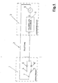
- Fig. 1
- eine Prinzipschaltung einer elektronischen Einrichtung zur Fehlerdiagnose eines Schaltgerätes,
- Fig. 2
- eine Schaltungsanordnung für eine Halbwellendecodierchaltungsanordnung,
- Fig. 3
- ein Blockschaltbild einer Applikationsschaltung für eine Auswerteeinheit,
- Fig. 4
- ein Meßdiagramm, welches das Einschaltverhalten der Auwerteeinheit darstellt und
- Fig. 5
- ein Meßdiagramm, welches das Ausschaltverhalten der Auswerteeinheit darstellt.
- Fig. 1
- a basic circuit of an electronic device for fault diagnosis of a switching device,
- Fig. 2
- a circuit arrangement for a half-wave decoding circuit arrangement,
- Fig. 3
- 2 shows a block diagram of an application circuit for an evaluation unit,
- Fig. 4
- a measurement diagram showing the switch-on behavior of the evaluation unit and
- Fig. 5
- a measurement diagram showing the switch-off behavior of the evaluation unit.
Eine elektronische Einrichtung zur Fehlerdiagnose in einem elektrischen System nach
Figur 1 besteht im wesentlichen aus einem Schaltgerät 1, das über eine lange
zweipolige Zuleitung 2 mit einer Auswerteeinheit 3 in Verbindung steht.An electronic device for fault diagnosis in an electrical system
Figure 1 consists essentially of a
Das Schaltgerät 1 nach Art eines Wechselschalters kann beispielsweise den
Schaltausgang eines Druckschalters darstellen, der bei Erreichen eines definierten
Druckes in einem Druckbehälter seinen Schaltzustand ändert. An den dabei
wechselnd betätigten Kontakten 4 und 5 des Schaltgerätes 1 ist je eine Diode 6 und
6' mit ihrem einen Anschluß angebracht. die Dioden 6 und 6' sind antiparallel
zueinander geschaltet und mit ihrem anderen Anschluß miteinander und mit einer
Leitung der zweipoligen Zuleitung 2 verbunden. Die andere Leitung der zweipoligen
Zuleitung 2 geht von einem Schaltkontakt 2 des Schaltgerätes 1 aus. Die Zuleitung 2
ist an die Auswerteeinheit 3 geführt. Die Auswerteeinheit 3 beinhaltet einen
Wechselsignal-Generator 8 sowie eine Halbwellendecodier-Schaltungsanordnung 9. The
Das Schaltgerät 1, der Wechselsignal-Generator 8 sowie die Halbwellendecodier-Schaltungsanordnung
9 bilden einen Signalflußkreis, in dem das vom Wechselsignal-Generator
8 generierte nullsymmetrische Niederfrequenz-Wechselsignal von ca. 660
Hz mittels der im Schaltgerät 1 antiparallel angeordneten Dioden 6 und 6' je nach
Schaltzustand eine Halbwellen-Filterung erfährt. Aus der so gefilterten und über die
Zuleitung 2 an die Auswerteeinheit 3 rückübertragenen positiven und negativen
Halbwelle erkennt die Halbwellendecodier-Schaltungsanordnung 9 den Schaltzustand
- betätigt oder nicht betätigt - des Schaltgerätes 1 und stellt diesen für eine
Weiterverarbeitung zur Verfügung. Die Halbwellendecodier-Schaltungsanordnung 9
analysiert darüber hinaus auch einen Fehlerzustand des Schaltgerätes 1. Erkennt die
Halbwellendecodier-Schaltungsanordnung 9 keine Halbwelle, d. h. kein
Eingangssignal, so liegt offensichtlich eine Unterbrechung vor, beispielsweise
aufgrund eines Leitungsbruches in der langen Zuleitung 2. Empfängt dagegen die
Halbwellendecodier-Schaltungsanordnung 9 beide Halbwellen des Niederfrequenz-Wechselsignals,
so läßt sich auf einen Leitungskurzschluß schließen. Die
Halbwellendecodier-Schaltungsanordnung 9 stellt auch diese Fehlerzustandsinformation
für eine Weiterverarbeitung, beispielsweise eine Anzeige in einer
zentralen Diagnoseeinheit des elektrischen Systems zur Verfügung.The
Die Halbwellendecodier-Schaltungsanordnung 9 besteht gemäß dem Schaltplan nach
Figur 2 im wesentlichen aus zwei ebenfalls antiparallel zueinander geschalteten und
mit den Eingängen E1 und E2 verbundenen Sendedioden von Optokopplem 10, 10',
die als Polaritätsfilter dienen und außerdem die galvanische Trennung zu den
Eingängen E1 und E2 gewährleisten. Den Schalttransistoren der Optokoppler 10 und
10' ist je ein RC-Glied 11, 11' als Tiefpaßfilter nachgeschaltet. Das RC-Glied 11, 11'
wandelt die mittels Optokoppler 10,10' gefilterte pulsierende Gleichspannung in eine
weitestgehend kontinuierliche Gleichspannung um. Durch die Schaltvorgänge der
Schalttransistoren der Optokoppler 10,10' stellt sich am Kondensator C im
eingeschwungenen Zustand eine Mittelspannung ein, die dem Mittelwert der
treibenden Halbwelle der Sendediode des jeweiligen Optokopplers 10, 10' umgekehrt
proportional ist. Der Rest-Ripple der sich einstellenden Mittelspannung wird durch die
Frequenz der pulsierenden Gleichspannung und durch die Zeitkonstanten TE und TL
bestimmt, gilt, daß TE << TL. Durch den Schmitt-Trigger 14, 14' wird die
Mittelspannung anschließend in ein eindeutiges Schaltsignal umgewandelt und an die
Ausgänge A1 sowie A2 überführt, so daß es sich digital weiterverarbeiten läßt. According to the circuit diagram according to FIG. 2, the half-wave
Bei einer Applikationsschaltung gemäß dem Blockschaltbild nach Figur 3 wird das der
6-kanaligen Auswerteeinheit 3 vom Schaltgerät 1 über die Zuleitung 2 zugeführte
Eingangssignal zunächst auf einen Eingangsfilter 12 gegeben. Die Auswerteeinheit 3
sendet über den integrierten Wechselsignal-Generator 8 ihr nullsymmetrisches
Niederfrequenz-Wechselsignal von ca. 660 Hz über die Zuleitung 2 zum Schaltgerät
1. Der Eingangsfilter 12 beinhaltet eine Transientenschutzschaltung, die eine
ausreichende Störfestigkeit im Sinne der elektromagnetischen Verträglichkeit (EMV)
sicherstellt. Dem Eingangsfilter 12 sind die als Polaritätsfilter 13, 13' dienenden
antiparallel geschalteten Sendedioden der Optokoppler 10, 10' nachgeschaltet. Diese
liefern ein im stationären Zustand antivatentes Signal. Nach den der galvanischen
Trennung dienenden Optikopplem 10, 10' passiert das jeweilige Halbwellensignal zur
Glättung einen Tiefpaßfilter in Form des RC-Gliedes 11,11' mit nachgeschaltetem
Schmitt-Trigger 14, 14'. Das so vorliegende digital weiterverarbeitbare Signal wird an
entsprechende Latch-Glieder 15, 15' weitergeleitet, die in Verbindung mit einer
Schnittstellenlogik 16 eine Anbindung an ein Bussystem gewährleisten. Damit ist das
über das Bussystem übertragbare Auswertesignal von einer in der Figur nicht
dargestellten übergeordneten Steuereinheit, beispielsweise einer
Fehlerdiagnoseeinheit erfaßbar und ausgebbar.In the case of an application circuit according to the block diagram according to FIG. 3, this becomes the
6-
In Figur 4 ist das Einschaltverhalten einer Applikationsschaltung anhand eines
Meßschriebes dargestellt. Die gemessene Zeitverzögerung beim Einschalten beträgt
lediglich T1 = 1,9 ms und wird durch die Entlade-Zeitkonstante TE sowie der
Ausschalt-Schwelle des Schmitt-Triggers bestimmt. Die Grenzfrequenz der
Halbwellendecodier-Schaltungsanordnung 9 in der Applikationsschaltung wird im
wesentlichen durch die Zeitkonstante des RC-Gliedes 11 von T = R * C ≈ 10 ms und
der Frequenz des Wechselsignal-Generators 8 von ca. 660 Hz bestimmt und führt in
Verbindung mit der Schalthysterese des Schmitt-Trigger 14 zu einer errechneten
maximalen System-Totzeit von Tsystot ≤ 8 ms.FIG. 4 shows the switch-on behavior of an application circuit using a measurement record. The measured time delay when switching on is only T 1 = 1.9 ms and is determined by the discharge time constant T E and the switch-off threshold of the Schmitt trigger. The cut-off frequency of the half-wave
Die Figur 5 zeigt das Ausschaltverhalten des Schmitt-Trigger 14 gemessen am
Ausgang A1 bzw. A2 des Schmitt-Triggers 14, bei der Applikationsschaltung anhand
eines weiteren Meßschriebes. Die gemessene Totzeit ergibt im Gegensatz zum
Einschalten beim Ausschalten hier einen längeren Zeitwert von T2 = 8,2 ms, bestimmt
durch die Lade-Zeitkonstante TL sowie der Einschalt-Schwelle des Schmitt-Triggers
14. Unter Zugrundelegung der Umladedauer des RC-Gliedes 11, der dafür benötigten
Impulse des Wechselsignal-Generators 8 und der Totzeiten Tsystot bzw. T2 ist die
Grenzfrequenz für die Umschaltung des Schaltgerätes 1 bei der
Applikationsschaltung auf maximal 100 Hz begrenzt. Um eine zuverlässige Funktion
der Halbwellendecodier-Schaltungsanordnung 9 sicherzustellen, muß die
Schaltfrequenz des Schaltgerätes 1 stets unterhalb ihrer Grenzfrequenz liegen. FIG. 5 shows the switch-off behavior of the
- 11
- SchaltgerätSwitchgear
- 22nd
- Zuleitung, zweipoligSupply line, two-pole
- 33rd
- AuswerteeinheitEvaluation unit
- 44th
- Kontakt, ersterContact, first
- 55
- Kontakt, zweiterContact, second
- 66
- Diodediode
- 77
- SchaltkontaktSwitch contact
- 88th
- Wechselsignal-GeneratorAlternating signal generator
- 99
- Halbwellendecodier-SchaltungsanordnungHalf-wave decoding circuitry
- 1010th
- OptokopplerOptocoupler
- 1111
- RC-GliedRC link
- 1212th
- EingangsfilterInput filter
- 1313
- PolaritätsfilterPolarity filter
- 1414
- Schmitt-TriggerSchmitt trigger
- 1515
- Latch-GliedLatch link
- 1616
- SchnittstellenlogikInterface logic
- E1E1
- Erster EingangFirst entrance
- E2E2
- Zweiter EingangSecond entrance
- A1A1
- Erster AusgangFirst exit
- A2A2
- Zweiter AusgangSecond exit
- CC.
- Kondensatorcapacitor
- RR
- Widerstandresistance
Claims (9)
dadurch gekennzeichnet,
daß das Schaltgerät (1) ein Wechselschalter ist, an dessen beiden wechselnd betätigbaren Kontakten (4, 5) je eine Diode mit ihrem einen Anschluß angebracht ist, die beide antiparallel zueinander geschaltet sind und deren anderer Anschluß miteinander und mit einer Leitung verbunden ist, und daß eine weitere Leitung von einem Schaltkontakt (7) des Schaltgerätes (1) ausgeht, wobei beide Leitungen die zweipolige Zuleitung (2) zum Eingang der Auswerteeinheit (3) bilden, die einen Wechselsignal-Generator (8) beinhaltet, der mit dem zu überwachenden Schaltgerät (1) und einer elektronischen Halbwellendecodier-Schaltungsanordnung (9) einen Signalflußkreis bildet.Electronic device for fault diagnosis of electrical systems, in particular of electropneumatic brake systems, in which the switching and fault status of at least one electrical switching device (1) integrated into the electrical system via a feed line (2) can be determined by means of an evaluation unit (3),
characterized,
that the switching device (1) is a two-way switch, on the two alternately operable contacts (4, 5) a diode is attached with its one connection, both of which are connected antiparallel to one another and whose other connection is connected to one another and to a line, and that a further line starts from a switching contact (7) of the switching device (1), both lines forming the two-pole feed line (2) to the input of the evaluation unit (3), which contains an alternating signal generator (8) which is to be monitored with the Switching device (1) and an electronic half-wave decoding circuit arrangement (9) forms a signal flow circuit.
dadurch gekennzeichnet,
daß die Halbwellendecodier-Schaltungsanordnung (9) aus zwei antiparallel geschalteten Polaritätsfiltern aufgebaut ist, denen zur Signalausgabe je ein Mittel zur Umwandlung der gefilterten pulsierenden Gleichspannung in eine kontinuierliche Gleichspannung nachgeschaltet ist.Electronic device according to claim 1,
characterized,
that the half-wave decoding circuit arrangement (9) is constructed from two anti-parallel polarity filters, each of which is followed by a means for converting the filtered pulsating DC voltage into a continuous DC voltage for signal output.
dadurch gekennzeichnet,
daß als Mittel zur Umwandlung der gefilterten pulsierenden Gleichspannung in eine kontinuierliche Gleichspannung ein Tiefpaßfilter in Form eines RC-Gliedes (11, 11') mit nachgeschaltetem Schmitt-Trigger (14, 14') vorgesehen ist. Electronic device according to claim 2,
characterized,
that a low-pass filter in the form of an RC element (11, 11 ') with a downstream Schmitt trigger (14, 14') is provided as a means for converting the filtered pulsating DC voltage into a continuous DC voltage.
dadurch gekennzeichnet,
daß zur galvanischen Trennung die beiden Polaritätsfilter je von der Eingangsleuchtdiode eines Optokopplers (10, 10') gebildet sind, über dessen ausgangsseitigen Schalttransistor die gefilterte pulsierende Gleichspannung erzeugbar ist.Electronic device according to claim 2,
characterized,
that the two polarity filters are each formed by the input light-emitting diode of an optocoupler (10, 10 ') for electrical isolation, via whose switching transistor on the output side the filtered pulsating DC voltage can be generated.
dadurch gekennzeichnet,
daß zur Anbindung der Auswerteeinheit (3) an eine übergeordnete Steuereinheit über ein Bussystem der Halbwellendecodier-Schaltungsanordnung (9) ausgangsseitig eine Schnittstelle zugeordnet ist, die aus einer Schnittstellenlogik (16) besteht, die mit den beiden Schmitt-Triggern (14, 14') je nachgeschalteten Latch-Gliedern (15, 15') verschaltet ist.Electronic device according to claim 1,
characterized,
that for the connection of the evaluation unit (3) to a higher-level control unit via a bus system of the half-wave decoding circuit arrangement (9), an interface is assigned on the output side, which consists of an interface logic (16) which is connected to the two Schmitt triggers (14, 14 ') depending on the downstream latch elements (15, 15 ') is connected.
dadurch gekennzeichnet,
daß zur Bereitstellung des von der Auswerteeinheit (3) erzeugten Ausgangssignals der Halbwellendecodier-Schaltungsanordnung (9) eine Flip-Flop-Einheit nachgeschaltet ist.Electronic device according to claim 1,
characterized,
that a flip-flop unit is connected downstream of the half-wave decoding circuit arrangement (9) to provide the output signal generated by the evaluation unit (3).
dadurch gekennzeichnet,
daß der Wechselsignal-Generator (8) mittels einer Kippschaltung mit Gegentaktstufe ein nullsymmetrisches und im Bereich der Niederfrequenz liegendes Wechselsignal generiert. Electronic device according to claim 1,
characterized,
that the alternating signal generator (8) generates a zero-symmetrical alternating signal lying in the range of the low frequency by means of a flip-flop with push-pull stage.
dadurch gekennzeichnet,
daß zur Feststellung des Schalt- und Fehlerzustandes mehrerer Schaltgeräte (1) die Halbwellendecodier-Schaltungsanordnung (9) mindestens der Anzahl der Schaltgeräte (1) entsprechend mehrkanalig ausgeführt ist.Electronic device according to claim 1,
characterized,
that to determine the switching and fault status of several switching devices (1), the half-wave decoding circuit arrangement (9) is designed at least to correspond to the number of switching devices (1).
dadurch gekennzeichnet,
daß zur Gewährleistung einer ausreichenden Störfestigkeit im Sinne der elektromagnetischen Verträglichkeit (EMV) die Halbwellendecodier-Schaltungsanordnung (9) einen Eingangsfilter (12) mit Transientenschutzschaltung aufweist.Electronic device according to claim 1,
characterized,
that the half-wave decoder circuit arrangement (9) has an input filter (12) with a transient protection circuit to ensure sufficient interference immunity in the sense of electromagnetic compatibility (EMC).
Applications Claiming Priority (2)
| Application Number | Priority Date | Filing Date | Title |
|---|---|---|---|
| DE1997158101 DE19758101C2 (en) | 1997-12-18 | 1997-12-18 | Electronic device for monitoring a switching device in an electrical system |
| DE19758101 | 1997-12-18 |
Publications (1)
| Publication Number | Publication Date |
|---|---|
| EP0924528A1 true EP0924528A1 (en) | 1999-06-23 |
Family
ID=7853517
Family Applications (1)
| Application Number | Title | Priority Date | Filing Date |
|---|---|---|---|
| EP98250435A Withdrawn EP0924528A1 (en) | 1997-12-18 | 1998-12-10 | Electronic device for diagnosing faults in electrical systems |
Country Status (2)
| Country | Link |
|---|---|
| EP (1) | EP0924528A1 (en) |
| DE (1) | DE19758101C2 (en) |
Cited By (4)
| Publication number | Priority date | Publication date | Assignee | Title |
|---|---|---|---|---|
| CN102520292A (en) * | 2011-12-26 | 2012-06-27 | 广州电缆厂有限公司 | Multi-core cable voltage test conversion device |
| CN106093758A (en) * | 2016-05-27 | 2016-11-09 | 奇瑞汽车股份有限公司 | A kind of automobile brake switch long duration test monitoring device and monitoring method |
| WO2019038122A1 (en) * | 2017-08-21 | 2019-02-28 | Knorr-Bremse Systeme für Schienenfahrzeuge GmbH | Test device and test method for an electro-pneumatic braking system of trains |
| CN113928365A (en) * | 2021-11-17 | 2022-01-14 | 中车南京浦镇车辆有限公司 | Circuit for releasing applied state of reliable output brake of rail transit vehicle |
Families Citing this family (5)
| Publication number | Priority date | Publication date | Assignee | Title |
|---|---|---|---|---|
| DE19947965C2 (en) * | 1999-10-05 | 2003-04-24 | Bosch Gmbh Robert | Motor vehicle control device and method for controlling a motor vehicle function |
| DE102004020997A1 (en) † | 2004-04-19 | 2005-11-03 | Pilz Gmbh & Co. Kg | Safety switching device for a safety circuit |
| DE102006038375A1 (en) * | 2006-08-11 | 2008-02-14 | Valeo Schalter Und Sensoren Gmbh | circuitry |
| DE102006054877A1 (en) * | 2006-11-20 | 2008-05-21 | Endress + Hauser Wetzer Gmbh + Co. Kg | Method and device for monitoring a switch unit |
| DE102007057990B3 (en) * | 2007-12-03 | 2009-04-16 | Knorr-Bremse Systeme für Nutzfahrzeuge GmbH | Method and circuit arrangement for monitoring devices triggered by electrical impulses |
Citations (4)
| Publication number | Priority date | Publication date | Assignee | Title |
|---|---|---|---|---|
| GB2079958A (en) * | 1980-07-10 | 1982-01-27 | Ramage Stanley Leonard | Circuit Breaker Test Apparatus |
| US4628268A (en) * | 1982-11-18 | 1986-12-09 | Mitsubishi Denki Kabushiki Kaisha | Test device for testing an actuator circuit |
| US5506573A (en) * | 1993-05-13 | 1996-04-09 | Server Technology, Inc. | Remote sensor and method for detecting the on/off status of an automatically controlled appliance |
| US5574385A (en) * | 1994-04-28 | 1996-11-12 | Ics Triplex, Inc. | Testable solid state switch and related method |
Family Cites Families (3)
| Publication number | Priority date | Publication date | Assignee | Title |
|---|---|---|---|---|
| DE4012109C2 (en) * | 1990-04-14 | 1999-06-10 | Bosch Gmbh Robert | Device for monitoring the function of an electrical / electronic switching device, its connected consumer, a control and its connecting line |
| DE4443941C2 (en) * | 1994-12-09 | 1998-12-17 | Knorr Bremse Systeme | Method and device for checking a sensor |
| DE19534665C1 (en) * | 1995-09-19 | 1996-07-25 | Endress Hauser Gmbh Co | Electronic switching device responding to monitored physical parameter |
-
1997
- 1997-12-18 DE DE1997158101 patent/DE19758101C2/en not_active Expired - Fee Related
-
1998
- 1998-12-10 EP EP98250435A patent/EP0924528A1/en not_active Withdrawn
Patent Citations (4)
| Publication number | Priority date | Publication date | Assignee | Title |
|---|---|---|---|---|
| GB2079958A (en) * | 1980-07-10 | 1982-01-27 | Ramage Stanley Leonard | Circuit Breaker Test Apparatus |
| US4628268A (en) * | 1982-11-18 | 1986-12-09 | Mitsubishi Denki Kabushiki Kaisha | Test device for testing an actuator circuit |
| US5506573A (en) * | 1993-05-13 | 1996-04-09 | Server Technology, Inc. | Remote sensor and method for detecting the on/off status of an automatically controlled appliance |
| US5574385A (en) * | 1994-04-28 | 1996-11-12 | Ics Triplex, Inc. | Testable solid state switch and related method |
Cited By (7)
| Publication number | Priority date | Publication date | Assignee | Title |
|---|---|---|---|---|
| CN102520292A (en) * | 2011-12-26 | 2012-06-27 | 广州电缆厂有限公司 | Multi-core cable voltage test conversion device |
| CN106093758A (en) * | 2016-05-27 | 2016-11-09 | 奇瑞汽车股份有限公司 | A kind of automobile brake switch long duration test monitoring device and monitoring method |
| CN106093758B (en) * | 2016-05-27 | 2019-03-12 | 奇瑞汽车股份有限公司 | A kind of automobile brake switch endurance test monitoring device and monitoring method |
| WO2019038122A1 (en) * | 2017-08-21 | 2019-02-28 | Knorr-Bremse Systeme für Schienenfahrzeuge GmbH | Test device and test method for an electro-pneumatic braking system of trains |
| EP3871933A1 (en) * | 2017-08-21 | 2021-09-01 | KNORR-BREMSE Systeme für Schienenfahrzeuge GmbH | Test device and test method for an electro-pneumatic brake system of trains |
| CN113928365A (en) * | 2021-11-17 | 2022-01-14 | 中车南京浦镇车辆有限公司 | Circuit for releasing applied state of reliable output brake of rail transit vehicle |
| CN113928365B (en) * | 2021-11-17 | 2024-02-27 | 中车南京浦镇车辆有限公司 | Circuit for reliably outputting brake release application state of rail transit vehicle |
Also Published As
| Publication number | Publication date |
|---|---|
| DE19758101C2 (en) | 2002-06-20 |
| DE19758101A1 (en) | 1999-07-08 |
Similar Documents
| Publication | Publication Date | Title |
|---|---|---|
| EP2980659B1 (en) | Device and method for monitoring and switching a load circuit | |
| DE19653291C1 (en) | Sensor and evaluation system for end position and threshold value detection | |
| EP2980660B1 (en) | Method and device for monitoring and switching a load circuit | |
| EP0546455B1 (en) | Electronic control unit for switching a number of electrical loads | |
| DE102006030114B4 (en) | Safe input circuit with single-channel I / O connection for the input of a bus participant | |
| DE102006030448B4 (en) | Safe output circuit with a single-channel peripheral connection for the output of a bus participant | |
| DE19758101C2 (en) | Electronic device for monitoring a switching device in an electrical system | |
| DE3347458C2 (en) | ||
| EP1917651B1 (en) | Facility management system or danger warning system | |
| EP0608477B2 (en) | Semiconductor relay | |
| DE10351873A1 (en) | Device and method for fail-safe switching off an inductive load | |
| DE19515633A1 (en) | Electrical installation for building | |
| AT398501B (en) | DEVICE FOR SIGNAL-SAFE OPERATION OF SEVERAL ELECTRICAL CONSUMERS | |
| DE102016121255A1 (en) | Control module for an electromechanical switching unit, relay module and control device | |
| DE102010038459A1 (en) | Safety system, has safety module comprising system interface for direct contacting and communication with group protection unit, and load branch comprising another system interface for direct communication with safety module | |
| DE3515962A1 (en) | Arrangement for controlling and monitoring for failure, in a fashion which is reliable in terms of signalling technology, alternating current-fed double element lamps of a light signal, in particular a warning signal in railway signalling systems | |
| EP0034854B1 (en) | Monitoring circuit for a signalling circuit of a braking device of a vehicle | |
| EP1770456A1 (en) | Peripheral module for an automation apparatus | |
| DE2922782C2 (en) | Monitoring device for two-pole electrical command lines | |
| DE19823441C1 (en) | Digital input assembly for data processing system | |
| DE3029851A1 (en) | CIRCUIT ARRANGEMENT FOR THE SIGNAL TECHNOLOGY SAFE CONTROL OF A POWER CONSUMER | |
| DE102011088521B4 (en) | Expansion module for a security system | |
| DE19808595B4 (en) | Arrangement with an electrical load in series with two controllable semiconductor devices | |
| DE10151053B4 (en) | circuitry | |
| DE102010011199A1 (en) | Circuit arrangement for voltage measurement in an electric drive |
Legal Events
| Date | Code | Title | Description |
|---|---|---|---|
| PUAI | Public reference made under article 153(3) epc to a published international application that has entered the european phase |
Free format text: ORIGINAL CODE: 0009012 |
|
| AK | Designated contracting states |
Kind code of ref document: A1 Designated state(s): AT DE FR GB IT SE |
|
| AX | Request for extension of the european patent |
Free format text: AL;LT;LV;MK;RO;SI |
|
| 17P | Request for examination filed |
Effective date: 19990607 |
|
| AKX | Designation fees paid |
Free format text: AT DE FR GB IT SE |
|
| RAP1 | Party data changed (applicant data changed or rights of an application transferred) |
Owner name: KNORR-BREMSE MRP SYSTEME FUER SCHIENENFAHRZEUGE GM |
|
| STAA | Information on the status of an ep patent application or granted ep patent |
Free format text: STATUS: THE APPLICATION IS DEEMED TO BE WITHDRAWN |
|
| 18D | Application deemed to be withdrawn |
Effective date: 20030701 |