EP0924677A2 - Improved seal - Google Patents
Improved seal Download PDFInfo
- Publication number
- EP0924677A2 EP0924677A2 EP98124020A EP98124020A EP0924677A2 EP 0924677 A2 EP0924677 A2 EP 0924677A2 EP 98124020 A EP98124020 A EP 98124020A EP 98124020 A EP98124020 A EP 98124020A EP 0924677 A2 EP0924677 A2 EP 0924677A2
- Authority
- EP
- European Patent Office
- Prior art keywords
- tailpiece
- dentated
- tubular passage
- seal
- mouthpiece
- Prior art date
- Legal status (The legal status is an assumption and is not a legal conclusion. Google has not performed a legal analysis and makes no representation as to the accuracy of the status listed.)
- Granted
Links
Images
Classifications
-
- G—PHYSICS
- G09—EDUCATION; CRYPTOGRAPHY; DISPLAY; ADVERTISING; SEALS
- G09F—DISPLAYING; ADVERTISING; SIGNS; LABELS OR NAME-PLATES; SEALS
- G09F3/00—Labels, tag tickets, or similar identification or indication means; Seals; Postage or like stamps
- G09F3/02—Forms or constructions
- G09F3/03—Forms or constructions of security seals
- G09F3/0305—Forms or constructions of security seals characterised by the type of seal used
- G09F3/0347—Forms or constructions of security seals characterised by the type of seal used having padlock-type sealing means
- G09F3/0352—Forms or constructions of security seals characterised by the type of seal used having padlock-type sealing means using cable lock
Definitions
- the present invention is a seal of the type that includes a flat plate from which a tailpiece extends, said tailpiece being provided with a peripheral dentate in an intermediate area.
- This plate is linked sideways to a tubular passage, the inside of which has defined retainers which prevent the dentated piece passed through it from slipping back.
- the seal has as distinctive features the tubular tailpiece which defines both an annular reinforcement in the connecting area with the flat plate, and a thickening at the front end of the dentated piece, which enable it to be inserted into the tubular passage one way only.
- Utility Model 9200430 by the same applicant as the forerunner to the invention. It refers to a seal of the aforementioned type and its distinctive features are a mouthpiece at one end of the tubular passage to facilitate the insertion of the defined dentate in the intermediate part of the flexible tailpiece, and at the opposite end dentate retainers made up of flexible fins which lean slightly towards the centre part of the tubular passage.
- the dentate located in the intermediate area of the flexible tailpiece includes a series of frusto-conical teeth, the diameter of which increases towards the back.
- the other problem detected is the chance of the final user inserting the dentate into the tubular passage in a manner contrary to that intended by the manufacturer. This is possible due to the tapering of the teeth that cause the opening of the retention fins. The incorrect, which is to say backward, introduction of the tailpiece may cause the dentate to slip out easily from the tubular passage, since it will not be blocked by the retaining fins, thus making the seal ineffective.
- the improved seal which is the objective of this invention, includes extremely simple building details which solve the aforementioned problems.
- the flexible tailpiece has a spherical reinforcement in the connecting area with the flat plate. This is designed to absorb whatever strain may be caused by bending and/or twisting the tailpiece, thus preventing breakage in this area.
- both the flat plate and the flexible tailpiece will have an increasing section in the area next to the spherical reinforcement, thus distributing the possible strain over a longer area.
- the inclusion has been planned of a thickening at the front end of the dentated part which has constant cross section equal to the larger section of the teeth. Because this thickening is not conically-shaped, only through the mouthpiece end may be inserted into the tubular passage. This eliminates whatever possibility that previously existed of the user erroneously inserting in the incorrect end since, should he try to do so, the thickening will collide frontally against the retention fins which, in turn, will prevent it from entering.
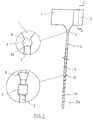
- the improved seal which is the subject matter of this invention has a flat plate (1) to which the tailpiece (2) and tubular passage (3) are linked.
- the seal In the connecting area of the plate (1) and the tailpiece (2), the seal has a spherical reinforcement (4).
- Both the flexible tailpiece (2) and the flat plate (1) have enlarged sections (2a) and (1a), respectively, in the connecting area with the spherical reinforcement (4).
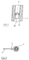
- the tubular passage (3) has a mouthpiece (3a) at one of its ends which extends towards the back area of the former in a cylindrical configuration (3b), finishing in retainers made up of flexible fins (3c).
- the flexible tailpiece (2) includes an intermediate dentated piece in which the frusto-conical teeth (5) are larger at the back.
- the front end of the dentated piece includes a thickening (6) which has constant cross section and equal to the larger base of the teeth (5).
- This thickening (6) can only be inserted into the tubular passage (3) with the mouthpiece end (3a) first. This is because its section, like that of the back end of the teeth, is slightly larger than the passage defined by the flexible fins (3), thus preventing it from being inserted in the rear end of the tubular passage first.
- the tailpiece (2) is extended from the thickening (6) in a final segment (2b) that is equipped with small peripheral nerves (2c) which prevent slippage when it is pulled to let pass the thickening (6) and all or some of the teeth (5) through the tubular passage (3) in order to obtain the closing and adjustment of the seal on any product whatsoever.
Landscapes
- Engineering & Computer Science (AREA)
- Computer Security & Cryptography (AREA)
- Physics & Mathematics (AREA)
- General Physics & Mathematics (AREA)
- Theoretical Computer Science (AREA)
- Gasket Seals (AREA)
- Sealing Devices (AREA)
- Diaphragms And Bellows (AREA)
- Coating By Spraying Or Casting (AREA)
- Glass Compositions (AREA)
- Package Frames And Binding Bands (AREA)
Abstract
Description
Claims (3)
- An improved seal of the type that includes a flat plate (1) from which a tailpiece (2) extends, which is provided with a peripheral dentate in an intermediate area. This plate (1) is linked sideways to a tubular passage (3) the ends of which are defined by a frusto-conical mouthpiece (3a) and retainers (3c) which prevent the slippage of the dentated section once it is inserted by means of the aforementioned mouthpiece. It is characterised because the dentated tailpiece (2) has a spherical reinforcement (4) in the connecting area with the plate (1), and a thickening (6) at the front end of the dentated piece (5) which only enables its introduction in the tubular passage (3) through of the end corresponding to mouthpiece (3a).
- A seal which, according to the proceeding Claim, is characterised in that both the flexible tailpiece (2) and the flat plate (1) have an increasing section in the connecting area with the spherical reinforcement (4).
- A seal, according to Claim 1, characterised in that the thickening (6) defined at the front end of the dentated piece has a constant cross section and equal to the larger portion of said dentated piece and slightly larger than the orifice defined by the retainers (3c) inside the tubular passage (3).
Applications Claiming Priority (2)
| Application Number | Priority Date | Filing Date | Title |
|---|---|---|---|
| ES9703287 | 1997-12-18 | ||
| ES9703287 | 1997-12-18 |
Publications (3)
| Publication Number | Publication Date |
|---|---|
| EP0924677A2 true EP0924677A2 (en) | 1999-06-23 |
| EP0924677A3 EP0924677A3 (en) | 2000-07-12 |
| EP0924677B1 EP0924677B1 (en) | 2004-01-28 |
Family
ID=8302190
Family Applications (1)
| Application Number | Title | Priority Date | Filing Date |
|---|---|---|---|
| EP98124020A Expired - Lifetime EP0924677B1 (en) | 1997-12-18 | 1998-12-17 | Improved seal |
Country Status (5)
| Country | Link |
|---|---|
| EP (1) | EP0924677B1 (en) |
| AT (1) | ATE258705T1 (en) |
| DE (1) | DE69821328T2 (en) |
| DK (1) | DK0924677T3 (en) |
| PT (1) | PT924677E (en) |
Cited By (2)
| Publication number | Priority date | Publication date | Assignee | Title |
|---|---|---|---|---|
| FR2863194A1 (en) * | 2003-12-09 | 2005-06-10 | Ellipse Ind | Injection mould for making locking plastic ties has insert for hole in tie block made in two sections with gap forming locking lips for flexible rod projections |
| WO2005057528A2 (en) * | 2003-12-09 | 2005-06-23 | Ellipse Industrie | Seal with identification support and injection mould used for production thereof |
Families Citing this family (1)
| Publication number | Priority date | Publication date | Assignee | Title |
|---|---|---|---|---|
| CN102542912B (en) * | 2011-12-23 | 2013-10-16 | 浙江顺舟电力高技术有限公司 | Internal back-off type multifunctional seal |
Citations (4)
| Publication number | Priority date | Publication date | Assignee | Title |
|---|---|---|---|---|
| US3712655A (en) * | 1970-11-16 | 1973-01-23 | Stoffel Steel Corp | Plastic seal |
| US3816879A (en) * | 1972-10-04 | 1974-06-18 | Dennison Mfg Co | Filamentary string fastener |
| US4240183A (en) * | 1978-02-17 | 1980-12-23 | Toska Co., Ltd. | Fastener |
| US4854014A (en) * | 1987-09-11 | 1989-08-08 | Toska Co., Ltd. | Fastener |
-
1998
- 1998-12-17 PT PT98124020T patent/PT924677E/en unknown
- 1998-12-17 DK DK98124020T patent/DK0924677T3/en active
- 1998-12-17 DE DE1998621328 patent/DE69821328T2/en not_active Expired - Lifetime
- 1998-12-17 EP EP98124020A patent/EP0924677B1/en not_active Expired - Lifetime
- 1998-12-17 AT AT98124020T patent/ATE258705T1/en not_active IP Right Cessation
Patent Citations (4)
| Publication number | Priority date | Publication date | Assignee | Title |
|---|---|---|---|---|
| US3712655A (en) * | 1970-11-16 | 1973-01-23 | Stoffel Steel Corp | Plastic seal |
| US3816879A (en) * | 1972-10-04 | 1974-06-18 | Dennison Mfg Co | Filamentary string fastener |
| US4240183A (en) * | 1978-02-17 | 1980-12-23 | Toska Co., Ltd. | Fastener |
| US4854014A (en) * | 1987-09-11 | 1989-08-08 | Toska Co., Ltd. | Fastener |
Cited By (3)
| Publication number | Priority date | Publication date | Assignee | Title |
|---|---|---|---|---|
| FR2863194A1 (en) * | 2003-12-09 | 2005-06-10 | Ellipse Ind | Injection mould for making locking plastic ties has insert for hole in tie block made in two sections with gap forming locking lips for flexible rod projections |
| WO2005057528A2 (en) * | 2003-12-09 | 2005-06-23 | Ellipse Industrie | Seal with identification support and injection mould used for production thereof |
| WO2005057528A3 (en) * | 2003-12-09 | 2005-09-09 | Ellipse Ind | Seal with identification support and injection mould used for production thereof |
Also Published As
| Publication number | Publication date |
|---|---|
| PT924677E (en) | 2004-06-30 |
| DE69821328T2 (en) | 2004-11-18 |
| EP0924677A3 (en) | 2000-07-12 |
| DE69821328D1 (en) | 2004-03-04 |
| DK0924677T3 (en) | 2004-06-07 |
| EP0924677B1 (en) | 2004-01-28 |
| ATE258705T1 (en) | 2004-02-15 |
Similar Documents
| Publication | Publication Date | Title |
|---|---|---|
| US5323554A (en) | Tube identification band | |
| EP1070512B1 (en) | A medical guide wire | |
| DE10111443B4 (en) | Endoscopic foreign object recovery tool | |
| CA2135143C (en) | Catheter joint with restraining device | |
| US4741117A (en) | Animal ear tag | |
| US3043007A (en) | Orthodontic brackets | |
| EP1062921A3 (en) | A catheter for delivering an appliance to be implanted with two connected tube elements | |
| US5039141A (en) | Annular catch for rapid connection of flexible or rigid tube | |
| CA2256323A1 (en) | Stent for vessel | |
| WO2001064265B1 (en) | Tube dependent anti-free-flow valve | |
| EP0867138A3 (en) | Article hanger | |
| AU637901B2 (en) | Improvements in or relating to milking apparatus | |
| EP0924677B1 (en) | Improved seal | |
| US5865558A (en) | Ball and socket joint body for control cable terminals | |
| IE51916B1 (en) | Improvements in and relating to ear tags | |
| CA2174044C (en) | Attachment and cable fastening device | |
| CA2300728A1 (en) | A push fit attachment | |
| NZ207898A (en) | Ear tag: parallel panels joined by less flexible connector | |
| EP0887015A3 (en) | Intra-line fishing rod | |
| AU597527B2 (en) | Slide fastener slider with detachable pull tab | |
| EP1285641B1 (en) | Device to drain away uncontrolled male urination | |
| EP0589601A1 (en) | Fitting for ball chains | |
| EP1191269A3 (en) | Tolerance-compensating disconnectable and non-disconnectable pipe connections | |
| DE3218937A1 (en) | BOTTLE CAP | |
| DE202008005269U1 (en) | Soother with a sucking part fixed to a mouth shield |
Legal Events
| Date | Code | Title | Description |
|---|---|---|---|
| PUAI | Public reference made under article 153(3) epc to a published international application that has entered the european phase |
Free format text: ORIGINAL CODE: 0009012 |
|
| AK | Designated contracting states |
Kind code of ref document: A2 Designated state(s): AT BE CH DE DK FI FR GB GR IE IT LI NL PT SE |
|
| AX | Request for extension of the european patent |
Free format text: AL;LT;LV;MK;RO;SI |
|
| PUAL | Search report despatched |
Free format text: ORIGINAL CODE: 0009013 |
|
| AK | Designated contracting states |
Kind code of ref document: A3 Designated state(s): AT BE CH CY DE DK ES FI FR GB GR IE IT LI LU MC NL PT SE |
|
| AX | Request for extension of the european patent |
Free format text: AL;LT;LV;MK;RO;SI |
|
| 17P | Request for examination filed |
Effective date: 20010108 |
|
| AKX | Designation fees paid |
Free format text: AT BE CH DE DK FI FR GB GR IE IT LI NL PT SE |
|
| GRAP | Despatch of communication of intention to grant a patent |
Free format text: ORIGINAL CODE: EPIDOSNIGR1 |
|
| GRAS | Grant fee paid |
Free format text: ORIGINAL CODE: EPIDOSNIGR3 |
|
| GRAA | (expected) grant |
Free format text: ORIGINAL CODE: 0009210 |
|
| AK | Designated contracting states |
Kind code of ref document: B1 Designated state(s): AT BE CH DE DK FI FR GB GR IE IT LI NL PT SE |
|
| PG25 | Lapsed in a contracting state [announced via postgrant information from national office to epo] |
Ref country code: LI Free format text: LAPSE BECAUSE OF FAILURE TO SUBMIT A TRANSLATION OF THE DESCRIPTION OR TO PAY THE FEE WITHIN THE PRESCRIBED TIME-LIMIT Effective date: 20040128 Ref country code: FI Free format text: LAPSE BECAUSE OF FAILURE TO SUBMIT A TRANSLATION OF THE DESCRIPTION OR TO PAY THE FEE WITHIN THE PRESCRIBED TIME-LIMIT Effective date: 20040128 Ref country code: CH Free format text: LAPSE BECAUSE OF FAILURE TO SUBMIT A TRANSLATION OF THE DESCRIPTION OR TO PAY THE FEE WITHIN THE PRESCRIBED TIME-LIMIT Effective date: 20040128 Ref country code: AT Free format text: LAPSE BECAUSE OF FAILURE TO SUBMIT A TRANSLATION OF THE DESCRIPTION OR TO PAY THE FEE WITHIN THE PRESCRIBED TIME-LIMIT Effective date: 20040128 |
|
| REG | Reference to a national code |
Ref country code: GB Ref legal event code: FG4D |
|
| REG | Reference to a national code |
Ref country code: CH Ref legal event code: EP |
|
| REG | Reference to a national code |
Ref country code: IE Ref legal event code: FG4D |
|
| REF | Corresponds to: |
Ref document number: 69821328 Country of ref document: DE Date of ref document: 20040304 Kind code of ref document: P |
|
| REG | Reference to a national code |
Ref country code: SE Ref legal event code: TRGR |
|
| REG | Reference to a national code |
Ref country code: GR Ref legal event code: EP Ref document number: 20040401399 Country of ref document: GR |
|
| REG | Reference to a national code |
Ref country code: DK Ref legal event code: T3 |
|
| REG | Reference to a national code |
Ref country code: PT Ref legal event code: SC4A Free format text: AVAILABILITY OF NATIONAL TRANSLATION Effective date: 20040428 |
|
| REG | Reference to a national code |
Ref country code: CH Ref legal event code: PL |
|
| ET | Fr: translation filed | ||
| PLBE | No opposition filed within time limit |
Free format text: ORIGINAL CODE: 0009261 |
|
| STAA | Information on the status of an ep patent application or granted ep patent |
Free format text: STATUS: NO OPPOSITION FILED WITHIN TIME LIMIT |
|
| 26N | No opposition filed |
Effective date: 20041029 |
|
| PG25 | Lapsed in a contracting state [announced via postgrant information from national office to epo] |
Ref country code: IT Free format text: LAPSE BECAUSE OF NON-PAYMENT OF DUE FEES Effective date: 20071217 |
|
| PGFP | Annual fee paid to national office [announced via postgrant information from national office to epo] |
Ref country code: SE Payment date: 20091211 Year of fee payment: 12 Ref country code: IE Payment date: 20091111 Year of fee payment: 12 Ref country code: DK Payment date: 20091201 Year of fee payment: 12 |
|
| PGFP | Annual fee paid to national office [announced via postgrant information from national office to epo] |
Ref country code: GB Payment date: 20091218 Year of fee payment: 12 |
|
| PGFP | Annual fee paid to national office [announced via postgrant information from national office to epo] |
Ref country code: GR Payment date: 20091126 Year of fee payment: 12 Ref country code: DE Payment date: 20091230 Year of fee payment: 12 |
|
| PGFP | Annual fee paid to national office [announced via postgrant information from national office to epo] |
Ref country code: IT Payment date: 20091217 Year of fee payment: 12 |
|
| PGRI | Patent reinstated in contracting state [announced from national office to epo] |
Ref country code: IT Effective date: 20110616 |
|
| REG | Reference to a national code |
Ref country code: DK Ref legal event code: EBP |
|
| GBPC | Gb: european patent ceased through non-payment of renewal fee |
Effective date: 20101217 |
|
| REG | Reference to a national code |
Ref country code: SE Ref legal event code: EUG |
|
| REG | Reference to a national code |
Ref country code: IE Ref legal event code: MM4A |
|
| PG25 | Lapsed in a contracting state [announced via postgrant information from national office to epo] |
Ref country code: SE Free format text: LAPSE BECAUSE OF NON-PAYMENT OF DUE FEES Effective date: 20101218 |
|
| PG25 | Lapsed in a contracting state [announced via postgrant information from national office to epo] |
Ref country code: IE Free format text: LAPSE BECAUSE OF NON-PAYMENT OF DUE FEES Effective date: 20101217 |
|
| REG | Reference to a national code |
Ref country code: DE Ref legal event code: R119 Ref document number: 69821328 Country of ref document: DE Effective date: 20110701 |
|
| PG25 | Lapsed in a contracting state [announced via postgrant information from national office to epo] |
Ref country code: GB Free format text: LAPSE BECAUSE OF NON-PAYMENT OF DUE FEES Effective date: 20101217 Ref country code: GR Free format text: LAPSE BECAUSE OF NON-PAYMENT OF DUE FEES Effective date: 20110704 Ref country code: DE Free format text: LAPSE BECAUSE OF NON-PAYMENT OF DUE FEES Effective date: 20110701 |
|
| PGRI | Patent reinstated in contracting state [announced from national office to epo] |
Ref country code: IT Effective date: 20110616 |
|
| PGFP | Annual fee paid to national office [announced via postgrant information from national office to epo] |
Ref country code: PT Payment date: 20111216 Year of fee payment: 14 Ref country code: FR Payment date: 20111221 Year of fee payment: 14 |
|
| PGFP | Annual fee paid to national office [announced via postgrant information from national office to epo] |
Ref country code: BE Payment date: 20111207 Year of fee payment: 14 |
|
| PGFP | Annual fee paid to national office [announced via postgrant information from national office to epo] |
Ref country code: NL Payment date: 20120102 Year of fee payment: 14 |
|
| REG | Reference to a national code |
Ref country code: PT Ref legal event code: MM4A Free format text: LAPSE DUE TO NON-PAYMENT OF FEES Effective date: 20130617 |
|
| BERE | Be: lapsed |
Owner name: S.A. *BROOKS TODO SEGURIDAD EN ESPANA Effective date: 20121231 |
|
| REG | Reference to a national code |
Ref country code: NL Ref legal event code: V1 Effective date: 20130701 |
|
| PG25 | Lapsed in a contracting state [announced via postgrant information from national office to epo] |
Ref country code: PT Free format text: LAPSE BECAUSE OF NON-PAYMENT OF DUE FEES Effective date: 20130617 |
|
| REG | Reference to a national code |
Ref country code: FR Ref legal event code: ST Effective date: 20130830 |
|
| PG25 | Lapsed in a contracting state [announced via postgrant information from national office to epo] |
Ref country code: BE Free format text: LAPSE BECAUSE OF NON-PAYMENT OF DUE FEES Effective date: 20121231 |
|
| PG25 | Lapsed in a contracting state [announced via postgrant information from national office to epo] |
Ref country code: NL Free format text: LAPSE BECAUSE OF NON-PAYMENT OF DUE FEES Effective date: 20130701 |
|
| PG25 | Lapsed in a contracting state [announced via postgrant information from national office to epo] |
Ref country code: FR Free format text: LAPSE BECAUSE OF NON-PAYMENT OF DUE FEES Effective date: 20130102 |