EP0926510A1 - Method of position determination of mobiles in an urban environment - Google Patents
Method of position determination of mobiles in an urban environment Download PDFInfo
- Publication number
- EP0926510A1 EP0926510A1 EP98403224A EP98403224A EP0926510A1 EP 0926510 A1 EP0926510 A1 EP 0926510A1 EP 98403224 A EP98403224 A EP 98403224A EP 98403224 A EP98403224 A EP 98403224A EP 0926510 A1 EP0926510 A1 EP 0926510A1
- Authority
- EP
- European Patent Office
- Prior art keywords
- path
- propagation
- delays
- angles
- mobile radio
- Prior art date
- Legal status (The legal status is an assumption and is not a legal conclusion. Google has not performed a legal analysis and makes no representation as to the accuracy of the status listed.)
- Granted
Links
Images

Classifications
-
- H—ELECTRICITY
- H04—ELECTRIC COMMUNICATION TECHNIQUE
- H04W—WIRELESS COMMUNICATION NETWORKS
- H04W64/00—Locating users or terminals or network equipment for network management purposes, e.g. mobility management
-
- G—PHYSICS
- G01—MEASURING; TESTING
- G01S—RADIO DIRECTION-FINDING; RADIO NAVIGATION; DETERMINING DISTANCE OR VELOCITY BY USE OF RADIO WAVES; LOCATING OR PRESENCE-DETECTING BY USE OF THE REFLECTION OR RERADIATION OF RADIO WAVES; ANALOGOUS ARRANGEMENTS USING OTHER WAVES
- G01S11/00—Systems for determining distance or velocity not using reflection or reradiation
- G01S11/02—Systems for determining distance or velocity not using reflection or reradiation using radio waves
-
- G—PHYSICS
- G01—MEASURING; TESTING
- G01S—RADIO DIRECTION-FINDING; RADIO NAVIGATION; DETERMINING DISTANCE OR VELOCITY BY USE OF RADIO WAVES; LOCATING OR PRESENCE-DETECTING BY USE OF THE REFLECTION OR RERADIATION OF RADIO WAVES; ANALOGOUS ARRANGEMENTS USING OTHER WAVES
- G01S5/00—Position-fixing by co-ordinating two or more direction or position line determinations; Position-fixing by co-ordinating two or more distance determinations
- G01S5/02—Position-fixing by co-ordinating two or more direction or position line determinations; Position-fixing by co-ordinating two or more distance determinations using radio waves
- G01S5/12—Position-fixing by co-ordinating two or more direction or position line determinations; Position-fixing by co-ordinating two or more distance determinations using radio waves by co-ordinating position lines of different shape, e.g. hyperbolic, circular, elliptical or radial
-
- H—ELECTRICITY
- H04—ELECTRIC COMMUNICATION TECHNIQUE
- H04L—TRANSMISSION OF DIGITAL INFORMATION, e.g. TELEGRAPHIC COMMUNICATION
- H04L25/00—Baseband systems
- H04L25/02—Details ; arrangements for supplying electrical power along data transmission lines
- H04L25/0202—Channel estimation
- H04L25/0212—Channel estimation of impulse response
Definitions
- the present invention relates to a method for locating mobile radio in an urban environment.
- the object of the invention is to overcome the aforementioned drawbacks.
- a first step represented in 1 in FIG. 1, it consists in calculating the impulse response h (t) of the propagation channel to estimate in step 2 the angles ⁇ m and the delays ⁇ m of the different paths as well as the attenuations ⁇ n of the waves propagated on each of the paths and finally to be calculated in step 3, from the delays ⁇ m calculated and from the impulse response h (t) of the channel, the distance d separating a mobile radio from the station transmission / reception.
- the calculation of the impulse response of the channel which is carried out at step 1 takes place on the signal obtained at the output of a multi-sensor antenna.
- the signal obtained at the output of a sensor n of the multi-sensor antenna is equal to the sum of the M signals s m (t) transmitted in the directions ⁇ m delayed by ⁇ m and multiplied by the response a i ( ⁇ m ) of the sensor i in the directions ⁇ m to which a noise b i (t) is added.
- the estimation of the angles ⁇ m and of the delays ⁇ m of step 2 is executed in a disjoint fashion, using the following matrix relation: with:
- the estimation of the time parameters ⁇ m is obtained from relation (12) by estimating a projector on the temporal space HH ⁇ and by applying either the method known by the Anglo-Saxon abbreviation MUSIC, from ⁇ Multi Signal Classification ⁇ by seeking the maxima of the quantity or is a column of the matrix M (13), or the deterministic method known as ⁇ maximum likelihood ⁇ using a criterion of the form
- the determination of the M couples makes it possible to locate the radio-mobiles.
- the determination of the couples takes place by considering four parameters ⁇ 1 , ⁇ 1 , ⁇ 2 , ⁇ 2 which are reduced to the knowledge of ⁇ 1 , ⁇ 2 and the delays ⁇ 1 , ⁇ 2 .
- the distance d ( ⁇ 2 - ⁇ 1 )vs ⁇ 1 ⁇ 2 1 ⁇ -1
- ⁇ 1 and ⁇ 2 denote the attenuations of the first and second paths and ⁇ the loss due to the reflection of the second path.
- the attenuations ⁇ 1 and ⁇ 2 are obtained from the couples ( ⁇ 1 , ⁇ 1 ; ⁇ 2 , ⁇ 2 ) and from the matrix relation where ⁇ i corresponds to the attenuation of the i th path.
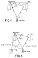
- Figure 5 shows that the information brought by any additional journey comes down to two parameters, and the there are also two unknown news. Consequently, a detection of more than two paths has no interest in the sense that it does not remove the unknowns. In these conditions, it suffices to limit the treatments considering only the direct route and another route any. Knowing the angles of arrival of the different paths, it is possible, thanks to a detailed topographic map in three dimensions of find the most likely points of reflection and thus go back to the emission source.
- the method operates by successive estimates by successively estimating the angles ⁇ and the delays ⁇ while associating them. Two methods can be used for this. The first consists in estimating the time parameters ⁇ m knowing the angles ⁇ m .
- Each column of the matrix M ⁇ forms a projector making it possible to find the corresponding delay ⁇ m by applying the MUSIC algorithm for a single emission source.
- the criterion used is of the form:
- the estimation of the parameters ⁇ m and ⁇ m takes place jointly by applying methods for determining the impulse responses based on a decomposition into subspaces, a sub -signal space of dimension M equals the number of sources and a noise subspace, complementary to the signal subspace of dimension N (L + 1) -M, or by applying the maximum likelihood method.
- a P Rh projector is created from the autocorrelation matrix of the filters
- the parameters sought are the minimum of the criterion
- the same type of optimization can be used to optimize the search for delays ⁇ m .
- Another optimization mode can be implemented by an approximate version of the maximum likelihood following for example the method described in IEEE transaction on signal processing, Vol. 39, N11, November 1991 of the authors M. Viberg, B. Ottersten, T. Kailath having for title: ⁇ Detection and estimation in sensor arrays using weighted subspace fitting ⁇ .
Abstract
Description
La présente invention concerne un procédé de localisation de radio-mobiles en milieu urbain.The present invention relates to a method for locating mobile radio in an urban environment.
Elle s'applique notamment à la localisation et au suivi de radio-mobiles dans un réseau GSM pour anticiper leur passage d'une cellule à la suivante et améliorer la réception des stations de base par la connaissance de la position des radio-mobiles émetteurs.It applies in particular to the location and monitoring of in a GSM network to anticipate their passage from a cell to the next and improve the reception of base stations by the knowledge of the position of the transmitting radio mobiles.
Dans des configurations simples de propagation, la localisation de radio-mobiles est traditionnellement obtenue à l'aide de radio-goniomètres disposés en des lieux déterminés d'un territoire. La position d'un radio-mobile peut alors être déterminée par triangulation en reportant sur une carte géographique les lieux où sont situés les radiogoniomètres ainsi que les directions d'arrivée sur ceux ci des ondes radioélectriques émises par le radio-mobile.In simple propagation configurations, localization of mobile radio is traditionally obtained using radio-goniometers arranged in determined places of a territory. The position of a mobile radio can then be determined by triangulation in showing on a geographical map the places where the direction finders as well as the directions of arrival on these waves radio signals emitted by the mobile radio.
Cependant, cette méthode qui repose sur l'exploitation des seuls chemins de propagation directs apparaít difficilement applicable dans le cas où les ondes empruntent plusieurs trajets et est également lourde de mise en oeuvre car elle nécessite plusieurs stations de réception. Ce type de propagation est notamment celui qui est rencontré en milieu urbain dans les réseaux de communication radio-mobiles cellulaires, où le spectre des communications est situé dans une gamme d'ultra hautes fréquences s'étendant typiquement de 30 MHz à 3 GHz pour le réseau GSM. Pour cette gamme de fréquences la propagation des ondes radioélectriques entre un émetteur et un récepteur peut empreinter des trajets multiples dus aux réflexions et aux diffractions sur des obstacles interposés sur le chemin de propagation direct entre l'émetteur et le récepteur. La gamme des fréquences utilisées est aussi la cause de trajets diffus, aussi bien temporellement que spatialement, qui dégradent les performances des liaisons.However, this method which relies on the exploitation of the only direct propagation paths appear difficult to apply in the case where the waves take several paths and is also fraught with stakes because it requires several receiving stations. This kind of spread is especially one that is encountered in urban areas in cellular radio communication networks, where the spectrum of communications is located in a range of ultra high frequencies typically ranging from 30 MHz to 3 GHz for the GSM network. For this frequency range the propagation of radio waves between a transmitter and receiver can use multiple paths due to reflections and diffractions on obstacles interposed on the way to direct propagation between the transmitter and the receiver. The range of frequencies used is also the cause of diffuse paths, as well temporally than spatially, which degrade the performance of connections.
Le but de l'invention est de pallier les inconvénients précités.The object of the invention is to overcome the aforementioned drawbacks.
A cet effet, l'invention a pour objet un procédé de localisation spatio-temporelle d'un radio-mobile relativement à une station de base émettrice/réceptrice caractérisé en ce qu'il consiste :
- à calculer la réponse impulsionnelle du canal de propagation entre le radio-mobile et la station émettrice/réceptrice,
- à estimer à partir de la réponse impulsionnelle les couples (angles, retard) du trajet de propagation direct et des multitrajets résultats de réflexions sur des obstacles situés dans le champ de propagation des ondes entre la station de base et le radio-mobile,
- à calculer l'atténuation αi de l'onde propagée par chaque trajet,
- et à calculer la distance d séparant la station émettrice/réceptrice du radio-mobile en considérant seulement les retards et les atténuations du trajet direct et d'un trajet non direct quelconque.
- calculating the impulse response of the propagation channel between the mobile radio and the transmitting / receiving station,
- to estimate from the impulse response the couples (angles, delay) of the direct propagation path and multi-path results of reflections on obstacles located in the wave propagation field between the base station and the mobile radio,
- calculating the attenuation α i of the wave propagated by each path,
- and calculating the distance d separating the transmitting / receiving station from the mobile radio by considering only the delays and attenuations of the direct path and of any non-direct path.
D'autres caractéristiques et avantages de l'invention apparaítront à l'aide de la description qui suit faite en regard des dessins annexés qui représentent :
- la figure 1 le procédé selon l'invention sous la forme d'un organigramme,
- la figure 2, un modèle de réception monocapteur,
- la figure 3, une illustration d'une réception multicapteur par une antenne circulaire,
- les figures 4 et 5, une illustration d'une transmission à deux ou trois trajets en milieu urbain.
- FIG. 1 the method according to the invention in the form of a flowchart,
- FIG. 2, a single-sensor reception model,
- FIG. 3, an illustration of a multisensor reception by a circular antenna,
- Figures 4 and 5, an illustration of a two- or three-way transmission in an urban environment.
Le procédé selon l'invention se déroule de la façon représentée à
la figure 1 suivant trois étapes principales. Dans une première étape,
représentée en 1 à la figure 1, il consiste à calculer la réponse
impulsionnelle h(t) du canal de propagation pour estimer à l'étape 2 les
angles m et les retards τm des différents trajets ainsi que les atténuations αn
des ondes propagées sur chacun des trajets et enfin à calculer à l'étape 3, à
partir des retards τm calculés et de la réponse impulsionnelle h(t) du canal,
la distance d séparant un radio-mobile de la station d'émission/réception.The method according to the invention takes place as shown in Figure 1 according to three main steps. In a first step, represented in 1 in FIG. 1, it consists in calculating the impulse response h (t) of the propagation channel to estimate in
Le calcul de la réponse impulsionnelle du canal qui est effectué à
l'étape 1 a lieu sur le signal obtenu à la sortie d'une antenne multi-capteurs.The calculation of the impulse response of the channel which is carried out at
En présence de plusieurs trajets M d'émission bande étroite de
radio-mobiles, le signal obtenu à la sortie d'un capteur n de l'antenne
multi-capteurs est égal à la somme des M signaux sm(t) émis dans les
directions m retardés de τm et multipliés par la réponse ai(m) du capteur i
dans les directions m à laquelle s'ajoute un bruit bi(t). Dans l'hypothèse
d'une transmission numérique à bande étroite de fréquence, une
représentation de la sortie vectorielle de l'antenne composée de N capteurs
s'obtient en concaténant la sortie xi(t) de chaque capteur, chaque sortie xi(t)
vérifiant la relation :
En introduisant un vecteur directionnel a(m) tel que
En rassemblant les vecteurs directionnels a(m) dans une
matrice
![]()
![]()
Suivant le modèle de propagation qui est représenté
schématiquement à la figure 2, le signal x(t) qui est obtenu à la sortie d'un
capteur de réception est un signal de la forme :
Dans le cas d'une réception sur l'antenne composée de
multi-capteurs, comme cela est représenté à la figure 3, la réponse
impulsionnelle du canal est modifiée par la réponse de l'antenne suivant les
directions d'arrivée. Cette réponse est de la forme :
En mode échantillonné, la réponse du canal de bande B prend la
forme :
Cette réponse peut être estimée par un filtre causal, à réponse
impulsionnelle finie de longueur L et de coefficients tels que :
Suivant un premier mode de réalisation de l'invention, l'estimation
des angles m et des retards τm de l'étape 2, est exécutée de façon disjointe,
en utilisant la relation matricielle suivante :
![]()


![]()
L'estimation des paramètres temporels τm s'obtient à partir de la
relation (12) en estimant un projecteur
![]()

![]()
![]()
![]()
![]()
![]()
Une description de la méthode MUSIC peut être trouvée dans l'article de M. Ralph O. Schmitt ayant pour titre 〈〈 Multiple source DF signal processing : An experimental system 〉〉 publiée dans IEEE transaction on antennas and propagation AP34 N° 3 March 1986.A description of the MUSIC method can be found in the article by M. Ralph O. Schmitt entitled 〈〈 Multiple source DF signal processing: An experimental system 〉〉 published in IEEE transaction on antennas and propagation AP34 N ° 3 March 1986.
La détermination des M couples (m, τm) permet de localiser les
radio-mobiles. Dans le cas où, comme cela est représenté à la figure 4,
seulement deux trajets, un trajet direct et un trajet comportant une réflexion
sont sélectionnés, la détermination des couples a lieu en considérant quatre
paramètres 1, τ1, 2, τ2 qui se ramènent à la connaissance de 1, 2 et
des retards τ1, τ2. En appelant d la distance du trajet direct qui sépare
l'émetteur radio-mobile 4 d'un récepteur 5 et d1, d2 les distances du trajet
indirect séparant respectivement le récepteur 5 d'un obstacle 6 sur lequel
l'onde indirecte est réfléchie et l'émetteur 4 de l'obstacle 6, la distance d est
fournie par la relation :

Comme la perte de puissance dans une propagation libre se fait
en
![]()
![]()
S'il y a plus de deux trajets, la figure 5 montre que l'information apportée par tout trajet supplémentaire se résume à deux paramètres, et les nouvelles inconnues sont également au nombre de deux. En conséquence, une détection de plus de deux trajets n'a pas d'intérêt dans le sens où elle ne supprime pas les inconnues. Il suffit dans ces conditions de limiter les traitements en considérant seulement le trajet direct et un trajet autre quelconque. Connaissant les angles d'arrivée des différents trajets, il est possible, grâce à une carte topographique détaillée en trois dimensions de trouver les points de réflexion les plus probables et ainsi de remonter à la source d'émission.If there are more than two paths, Figure 5 shows that the information brought by any additional journey comes down to two parameters, and the there are also two unknown news. Consequently, a detection of more than two paths has no interest in the sense that it does not remove the unknowns. In these conditions, it suffices to limit the treatments considering only the direct route and another route any. Knowing the angles of arrival of the different paths, it is possible, thanks to a detailed topographic map in three dimensions of find the most likely points of reflection and thus go back to the emission source.
D'autres modes d'estimation des paramètres sont également possibles.Other modes of parameter estimation are also possible.
L'estimation disjointe des paramètres décrite précédemment a l'avantage de réduire l'espace de recherche. Cependant, dans cette méthode , les angles et les retards ne sont pas associés si bien qu'elle souffre d'un manque de résolution pour estimer les retards proches.The disjoint estimation of the parameters described above has the advantage of reducing the search space. However, in this method, angles and delays are not associated so it suffers from a lack of resolution to estimate near delays.
D'autres modes de mise en oeuvre de l'invention permettent d'associer les paramètres en estimant la matrice des atténuations Ω avec les différentes combinaisons (m, τm) possibles en cherchant les couples rendant la matrice Ω la plus diagonale possible. Other embodiments of the invention make it possible to associate the parameters by estimating the matrix of the attenuations Ω with the different combinations ( m , τ m ) possible by seeking the couples making the matrix Ω as diagonal as possible.
Selon un deuxième mode de mise en oeuvre de l'invention, le procédé opère par estimations successives en estimant successivement les angles et les retards τ tout en les associant. Pour cela, deux méthodes peuvent être utilisées. La première consiste à estimer les paramètres temporels τm connaissant les angles m.According to a second embodiment of the invention, the method operates by successive estimates by successively estimating the angles and the delays τ while associating them. Two methods can be used for this. The first consists in estimating the time parameters τ m knowing the angles m .
En estimant des angles ∧m par la méthode MUSIC ou la méthode
du maximum de vraisemblance l'estimation des retards τm est obtenue en
estimant la matrice ![]()
![]()
![]()
![]()
Chaque colonne de la matrice M ∧ forme un projecteur permettant de trouver le retard correspondant τm en appliquant l'algorithme MUSIC pour une seule source d'émission.Each column of the matrix M ∧ forms a projector making it possible to find the corresponding delay τ m by applying the MUSIC algorithm for a single emission source.
Le critère utilisé est de la forme :

L'estimation des retards peut également être obtenue par
corrélation. En considérant que le signal reçu sur un capteur de M sources
est de la forme :
![]()

![]()
L'autocorrélation d'une des composantes de ![]()
![]()
De façon similaire à la méthode précédente, il est aussi possible
d'estimer les paramètres spatiaux m connaissant les retards τm. Ceux-ci
sont obtenus en calculant l'équation matricielle :
![]()
![]()
Chacune des méthodes utilisées dans ce deuxième mode de réalisation du procédé selon l'invention permet après avoir estimé les angles ou les retards de trouver les autres inconnues par M recherches en une dimension. Elles ont pour avantage de repousser certaines ambiguïtés, mais la seconde recherche apparaít très dépendante de la qualité de la première estimation. Une alternative serait d'effectuer, comme cela a été décrit par M. J. GROUFFAUD dans son mémoire de thèse de Doctorat de l'Ecole Normale Supérieure de Cachan de juin 1997 intitulée 〈〈 Identification spatio-temporelle de canaux de propagation à trajets multiples 〉〉, des recherches successives en alternant les méthodes pour affiner la précision de l'estimation des paramètres.Each of the methods used in this second mode of realization of the method according to the invention allows after having estimated the angles or delays in finding the other unknowns by M searches in one dimension. They have the advantage of rejecting certain ambiguities, but the second search appears very dependent on the quality of the first estimate. An alternative would be to perform, as described by M. J. GROUFFAUD in his doctoral dissertation of the School Normale Supérieur de Cachan from June 1997 entitled 〈〈 Identification spatio-temporal of multipath propagation channels des, successive searches by alternating methods to refine precision estimation of the parameters.
Enfin, suivant un troisième mode de réalisation du procédé selon l'invention, l'estimation des paramètres m et τm a lieu de façon conjointe en appliquant des méthodes de détermination des réponses impulsionnelles fondées sur une décomposition en sous-espaces, un sous-espace signal de dimension M égale le nombre de sources et un sous-espace bruit, complémentaire du sous-espace signal de dimension N(L + 1)-M, ou en appliquant la méthode du maximum de vraisemblance.Finally, according to a third embodiment of the method according to the invention, the estimation of the parameters m and τ m takes place jointly by applying methods for determining the impulse responses based on a decomposition into subspaces, a sub -signal space of dimension M equals the number of sources and a noise subspace, complementary to the signal subspace of dimension N (L + 1) -M, or by applying the maximum likelihood method.
Pour estimer conjointement les angles et les retards par la
méthode des sous-espaces, un projecteur P Rh est créé à partir de la matrice
d'autocorrélation des filtres

L'estimation h ∧ du vecteur 
![]()
![]()
Dans la recherche des paramètres par la méthode du maximum
de vraisemblance les paramètres cherchés sont les minimum du critère,

Cette recherche a lieu dans l'espace de dimension M × 2 des paramètres (1, τ1, ···, M, τM).This research takes place in the space of dimension M × 2 of the parameters ( 1 , τ 1 , ···, M , τ M ).
L'optimisation des différents modes de réalisation du procédé
selon l'invention peut avoir lieu en appliquant une méthode connue
d'optimisation du type Gauss-Newton. Après avoir trouvé un point
d'initialisation par les méthodes décrites précédentes, une optimisation des
angles m peut avoir lieu en déroulant l'algorithme suivant :
Le même type d'optimisation peut être utilisé pour optimiser la recherche des retards τm.The same type of optimization can be used to optimize the search for delays τ m .
Un autre mode d'optimisation peut être mis en oeuvre par une
version approchée du maximum de vraisemblable suivant par exemple la
méthode décrite dans IEEE transaction on signal processing, Vol. 39, N11,
Novembre 1991 des auteurs M. Viberg, B. Ottersten, T. Kailath ayant pour
titre : 〈〈 Detection and estimation in sensor arrays using weighted subspace
fitting 〉〉.


Claims (9)

Applications Claiming Priority (2)
| Application Number | Priority Date | Filing Date | Title |
|---|---|---|---|
| FR9716341A FR2773039B1 (en) | 1997-12-23 | 1997-12-23 | METHOD OF SPATIO-TEMPORAL LOCATION OF RADIO-MOBILES IN URBAN AREAS |
| FR9716341 | 1997-12-23 |
Publications (2)
| Publication Number | Publication Date |
|---|---|
| EP0926510A1 true EP0926510A1 (en) | 1999-06-30 |
| EP0926510B1 EP0926510B1 (en) | 2005-08-31 |
Family
ID=9514988
Family Applications (1)
| Application Number | Title | Priority Date | Filing Date |
|---|---|---|---|
| EP19980403224 Expired - Lifetime EP0926510B1 (en) | 1997-12-23 | 1998-12-18 | Method of position determination of mobiles in an urban environment |
Country Status (3)
| Country | Link |
|---|---|
| EP (1) | EP0926510B1 (en) |
| DE (1) | DE69831388T2 (en) |
| FR (1) | FR2773039B1 (en) |
Cited By (12)
| Publication number | Priority date | Publication date | Assignee | Title |
|---|---|---|---|---|
| EP1077536A2 (en) * | 1999-08-19 | 2001-02-21 | Omron Corporation | Transmitter apparatus and communication method including method of detecting the position of a receiver |
| WO2001018560A1 (en) * | 1999-09-02 | 2001-03-15 | Nokia Corporation | Distance estimation between transmitter and receiver |
| FR2805614A1 (en) * | 2000-02-25 | 2001-08-31 | Thomson Csf | Location method for radio signal sources uses network of sensors linked to two receivers providing data for processing with covariance matrix method |
| FR2813465A1 (en) * | 2000-08-29 | 2002-03-01 | Mitsubishi Electric Inf Tech | METHOD OF JOINT CHANNEL ESTIMATION AND ARRIVAL DIRECTION |
| EP1221792A1 (en) * | 2001-01-09 | 2002-07-10 | Thales | Method and receiver for adaptive estimation of space and time parameters of a propagation channel |
| WO2002058290A1 (en) * | 2001-01-16 | 2002-07-25 | Bluesoft, Inc. | System and method for reducing multipath distortion in wireless distance measurement systems |
| WO2003019826A1 (en) * | 2001-08-31 | 2003-03-06 | Koninklijke Philips Electronics N.V. | Radio station with multipath signal modeling |
| US6731908B2 (en) | 2001-01-16 | 2004-05-04 | Bluesoft, Inc. | Distance measurement using half-duplex RF techniques |
| US6859761B2 (en) | 2001-01-16 | 2005-02-22 | Bluesoft Ltd. | Accurate distance measurement using RF techniques |
| WO2009065943A1 (en) * | 2007-11-23 | 2009-05-28 | Thales | Method of multi-transmitter and multi-path aoa-tdoa location comprising a sub-method for synchronizing and equalizing the receiving stations |
| FR2989546A1 (en) * | 2012-04-13 | 2013-10-18 | Thales Sa | Method for determination of travel time of communication signal between terrestrial transmitter and mobile receiver, involves providing minimum value of measurements for different positions such that minimum value is retained |
| US20180356494A1 (en) * | 2017-06-13 | 2018-12-13 | Massachusetts Institute Of Technology | Wideband ranging system |
Families Citing this family (10)
| Publication number | Priority date | Publication date | Assignee | Title |
|---|---|---|---|---|
| US7667647B2 (en) | 1999-03-05 | 2010-02-23 | Era Systems Corporation | Extension of aircraft tracking and positive identification from movement areas into non-movement areas |
| US8203486B1 (en) | 1999-03-05 | 2012-06-19 | Omnipol A.S. | Transmitter independent techniques to extend the performance of passive coherent location |
| US7739167B2 (en) | 1999-03-05 | 2010-06-15 | Era Systems Corporation | Automated management of airport revenues |
| US7570214B2 (en) | 1999-03-05 | 2009-08-04 | Era Systems, Inc. | Method and apparatus for ADS-B validation, active and passive multilateration, and elliptical surviellance |
| US7782256B2 (en) | 1999-03-05 | 2010-08-24 | Era Systems Corporation | Enhanced passive coherent location techniques to track and identify UAVs, UCAVs, MAVs, and other objects |
| US7908077B2 (en) | 2003-06-10 | 2011-03-15 | Itt Manufacturing Enterprises, Inc. | Land use compatibility planning software |
| US8446321B2 (en) | 1999-03-05 | 2013-05-21 | Omnipol A.S. | Deployable intelligence and tracking system for homeland security and search and rescue |
| US7889133B2 (en) | 1999-03-05 | 2011-02-15 | Itt Manufacturing Enterprises, Inc. | Multilateration enhancements for noise and operations management |
| US7777675B2 (en) | 1999-03-05 | 2010-08-17 | Era Systems Corporation | Deployable passive broadband aircraft tracking |
| US7965227B2 (en) | 2006-05-08 | 2011-06-21 | Era Systems, Inc. | Aircraft tracking using low cost tagging as a discriminator |
Citations (3)
| Publication number | Priority date | Publication date | Assignee | Title |
|---|---|---|---|---|
| EP0701334A2 (en) * | 1994-08-18 | 1996-03-13 | Nokia Mobile Phones Ltd. | Method and device to measure the impulse response of a radio channel |
| WO1997023785A1 (en) * | 1995-12-22 | 1997-07-03 | University Of Technology, Sydney | Location and tracking system |
| WO1997046034A1 (en) * | 1996-05-27 | 1997-12-04 | Nokia Telecommunications Oy | Method for determining the position of a mobile station |
-
1997
- 1997-12-23 FR FR9716341A patent/FR2773039B1/en not_active Expired - Fee Related
-
1998
- 1998-12-18 DE DE1998631388 patent/DE69831388T2/en not_active Expired - Lifetime
- 1998-12-18 EP EP19980403224 patent/EP0926510B1/en not_active Expired - Lifetime
Patent Citations (3)
| Publication number | Priority date | Publication date | Assignee | Title |
|---|---|---|---|---|
| EP0701334A2 (en) * | 1994-08-18 | 1996-03-13 | Nokia Mobile Phones Ltd. | Method and device to measure the impulse response of a radio channel |
| WO1997023785A1 (en) * | 1995-12-22 | 1997-07-03 | University Of Technology, Sydney | Location and tracking system |
| WO1997046034A1 (en) * | 1996-05-27 | 1997-12-04 | Nokia Telecommunications Oy | Method for determining the position of a mobile station |
Cited By (21)
| Publication number | Priority date | Publication date | Assignee | Title |
|---|---|---|---|---|
| EP1077536A3 (en) * | 1999-08-19 | 2004-10-13 | Omron Corporation | Transmitter apparatus and communication method including method of detecting the position of a receiver |
| EP1077536A2 (en) * | 1999-08-19 | 2001-02-21 | Omron Corporation | Transmitter apparatus and communication method including method of detecting the position of a receiver |
| WO2001018560A1 (en) * | 1999-09-02 | 2001-03-15 | Nokia Corporation | Distance estimation between transmitter and receiver |
| FR2805614A1 (en) * | 2000-02-25 | 2001-08-31 | Thomson Csf | Location method for radio signal sources uses network of sensors linked to two receivers providing data for processing with covariance matrix method |
| WO2001065272A1 (en) * | 2000-02-25 | 2001-09-07 | Thales | Method for locating radioelectric sources using two-channel high resolution radiogoniometer |
| US6989789B2 (en) | 2000-02-25 | 2006-01-24 | Thales | Method for locating radioelectric sources using two-channel high resolution radiogoniometer |
| FR2813465A1 (en) * | 2000-08-29 | 2002-03-01 | Mitsubishi Electric Inf Tech | METHOD OF JOINT CHANNEL ESTIMATION AND ARRIVAL DIRECTION |
| EP1185004A1 (en) * | 2000-08-29 | 2002-03-06 | Mitsubishi Electric Information Technology Centre Europe B.V. | Joint angle of arrival and channel estimation method |
| US7283790B2 (en) | 2001-01-09 | 2007-10-16 | Thales | Blind process and receiver to determine space-time parameters of a propagation channel |
| FR2819357A1 (en) * | 2001-01-09 | 2002-07-12 | Thomson Csf | AUTODIDACTIVE METHOD AND RECEIVER FOR DETERMINING SPATIO-TEMPORAL PARAMETERS OF A PROPAGATION CHANNEL |
| EP1221792A1 (en) * | 2001-01-09 | 2002-07-10 | Thales | Method and receiver for adaptive estimation of space and time parameters of a propagation channel |
| US6731908B2 (en) | 2001-01-16 | 2004-05-04 | Bluesoft, Inc. | Distance measurement using half-duplex RF techniques |
| WO2002058290A1 (en) * | 2001-01-16 | 2002-07-25 | Bluesoft, Inc. | System and method for reducing multipath distortion in wireless distance measurement systems |
| US6859761B2 (en) | 2001-01-16 | 2005-02-22 | Bluesoft Ltd. | Accurate distance measurement using RF techniques |
| US6898415B2 (en) | 2001-01-16 | 2005-05-24 | Aeroscout, Inc. | System and method for reducing multipath distortion in wireless distance measurement systems |
| WO2003019826A1 (en) * | 2001-08-31 | 2003-03-06 | Koninklijke Philips Electronics N.V. | Radio station with multipath signal modeling |
| WO2009065943A1 (en) * | 2007-11-23 | 2009-05-28 | Thales | Method of multi-transmitter and multi-path aoa-tdoa location comprising a sub-method for synchronizing and equalizing the receiving stations |
| FR2924228A1 (en) * | 2007-11-23 | 2009-05-29 | Thales Sa | MULTI-EMITTER AND MULTI-PATH AOA-TDOA LOCATION METHOD COMPRISING A SYNCHRONIZATION AND EQUALIZATION SUB-PROCESS OF RECEPTION STATIONS |
| FR2989546A1 (en) * | 2012-04-13 | 2013-10-18 | Thales Sa | Method for determination of travel time of communication signal between terrestrial transmitter and mobile receiver, involves providing minimum value of measurements for different positions such that minimum value is retained |
| US20180356494A1 (en) * | 2017-06-13 | 2018-12-13 | Massachusetts Institute Of Technology | Wideband ranging system |
| US10705182B2 (en) * | 2017-06-13 | 2020-07-07 | Massachusetts Institute Of Technology | Wideband ranging system |
Also Published As
| Publication number | Publication date |
|---|---|
| FR2773039B1 (en) | 2000-03-17 |
| FR2773039A1 (en) | 1999-06-25 |
| DE69831388T2 (en) | 2006-06-14 |
| DE69831388D1 (en) | 2005-10-06 |
| EP0926510B1 (en) | 2005-08-31 |
Similar Documents
| Publication | Publication Date | Title |
|---|---|---|
| EP0926510B1 (en) | Method of position determination of mobiles in an urban environment | |
| EP2368133B1 (en) | Method for locating multiple rays of a source with or without aoa by multi-channel estimation of the tdoa and fdoa | |
| EP1259833B1 (en) | Method for locating radioelectric sources using two-channel high resolution radiogoniometer | |
| EP1500951B1 (en) | Method for the multistatic detection and locating of a mobile craft through the use of digital broadcasting transmitters | |
| EP2612166B1 (en) | Method and device for locating at least one obstacle in a communication network, corresponding computer program | |
| FR2753035A1 (en) | METHOD AND APPARATUS FOR POSITION SEARCHING IN A COMMUNICATION SYSTEM | |
| EP2428810B1 (en) | Multi-transmitter geo-positioning method by space-time processing. | |
| EP2579063B1 (en) | Method and system for locating interference by frequency sub-band | |
| EP1582888A1 (en) | Method for the blind wideband localization of one or more transmitters from a carrier that is passing by | |
| EP0991952B1 (en) | Radiogoniometry method and device co-operating in transmission | |
| EP3543745B1 (en) | Multi-antenna device for rejection of multipaths in a satellite navigation system and associated method | |
| EP1682923A1 (en) | Method for localising at least one emitter | |
| EP1291664B1 (en) | Method and system for cooperative radio direction finding in transmission mode | |
| US7783110B2 (en) | Semicoherent channel estimator | |
| EP1253435A1 (en) | Method and system for spatio-temporal estimation of one or several emitters | |
| FR3011086A1 (en) | METHOD FOR JOINTLY SYNCHRONIZING, IDENTIFYING, MEASURING, ESTIMATING THE PROPAGATION FILTER AND LOCATING USEFUL AND INTERFERING TRANSMITTERS | |
| EP1229696B1 (en) | Channel parameters estimation using maximum likelihood estimation | |
| EP3399328B1 (en) | Method and system for phdoa, pwdoa distributed location of emitting sources | |
| EP1446898B1 (en) | Multipath incident beam receiver | |
| EP1221792A1 (en) | Method and receiver for adaptive estimation of space and time parameters of a propagation channel | |
| EP2151697B1 (en) | System and method for locating a communicating mobile object | |
| EP0891049A1 (en) | Method for the estimation of the angular spread of a signal transmitted from a transmitter to a receiver and corresponding receiver |
Legal Events
| Date | Code | Title | Description |
|---|---|---|---|
| PUAI | Public reference made under article 153(3) epc to a published international application that has entered the european phase |
Free format text: ORIGINAL CODE: 0009012 |
|
| AK | Designated contracting states |
Kind code of ref document: A1 Designated state(s): DE FI FR GB IT NL SE |
|
| AX | Request for extension of the european patent |
Free format text: AL;LT;LV;MK;RO;SI |
|
| 17P | Request for examination filed |
Effective date: 19991227 |
|
| AKX | Designation fees paid |
Free format text: DE FI FR GB IT NL SE |
|
| RAP1 | Party data changed (applicant data changed or rights of an application transferred) |
Owner name: THALES |
|
| 17Q | First examination report despatched |
Effective date: 20040608 |
|
| GRAP | Despatch of communication of intention to grant a patent |
Free format text: ORIGINAL CODE: EPIDOSNIGR1 |
|
| GRAS | Grant fee paid |
Free format text: ORIGINAL CODE: EPIDOSNIGR3 |
|
| GRAA | (expected) grant |
Free format text: ORIGINAL CODE: 0009210 |
|
| AK | Designated contracting states |
Kind code of ref document: B1 Designated state(s): DE FI FR GB IT NL SE |
|
| PG25 | Lapsed in a contracting state [announced via postgrant information from national office to epo] |
Ref country code: NL Free format text: LAPSE BECAUSE OF FAILURE TO SUBMIT A TRANSLATION OF THE DESCRIPTION OR TO PAY THE FEE WITHIN THE PRESCRIBED TIME-LIMIT Effective date: 20050831 Ref country code: IT Free format text: LAPSE BECAUSE OF FAILURE TO SUBMIT A TRANSLATION OF THE DESCRIPTION OR TO PAY THE FEE WITHIN THE PRE;WARNING: LAPSES OF ITALIAN PATENTS WITH EFFECTIVE DATE BEFORE 2007 MAY HAVE OCCURRED AT ANY TIME BEFORE 2007. THE CORRECT EFFECTIVE DATE MAY BE DIFFERENT FROM THE ONE RECORDED.SCRIBED TIME-LIMIT Effective date: 20050831 Ref country code: FI Free format text: LAPSE BECAUSE OF FAILURE TO SUBMIT A TRANSLATION OF THE DESCRIPTION OR TO PAY THE FEE WITHIN THE PRESCRIBED TIME-LIMIT Effective date: 20050831 |
|
| REG | Reference to a national code |
Ref country code: GB Ref legal event code: FG4D Free format text: NOT ENGLISH |
|
| REF | Corresponds to: |
Ref document number: 69831388 Country of ref document: DE Date of ref document: 20051006 Kind code of ref document: P |
|
| PG25 | Lapsed in a contracting state [announced via postgrant information from national office to epo] |
Ref country code: SE Free format text: LAPSE BECAUSE OF FAILURE TO SUBMIT A TRANSLATION OF THE DESCRIPTION OR TO PAY THE FEE WITHIN THE PRESCRIBED TIME-LIMIT Effective date: 20051130 |
|
| GBT | Gb: translation of ep patent filed (gb section 77(6)(a)/1977) |
Effective date: 20051128 |
|
| NLV1 | Nl: lapsed or annulled due to failure to fulfill the requirements of art. 29p and 29m of the patents act | ||
| PLBE | No opposition filed within time limit |
Free format text: ORIGINAL CODE: 0009261 |
|
| STAA | Information on the status of an ep patent application or granted ep patent |
Free format text: STATUS: NO OPPOSITION FILED WITHIN TIME LIMIT |
|
| 26N | No opposition filed |
Effective date: 20060601 |
|
| PGFP | Annual fee paid to national office [announced via postgrant information from national office to epo] |
Ref country code: GB Payment date: 20141217 Year of fee payment: 17 Ref country code: DE Payment date: 20141209 Year of fee payment: 17 |
|
| REG | Reference to a national code |
Ref country code: FR Ref legal event code: PLFP Year of fee payment: 18 |
|
| PGFP | Annual fee paid to national office [announced via postgrant information from national office to epo] |
Ref country code: FR Payment date: 20151123 Year of fee payment: 18 |
|
| REG | Reference to a national code |
Ref country code: DE Ref legal event code: R119 Ref document number: 69831388 Country of ref document: DE |
|
| GBPC | Gb: european patent ceased through non-payment of renewal fee |
Effective date: 20151218 |
|
| PG25 | Lapsed in a contracting state [announced via postgrant information from national office to epo] |
Ref country code: DE Free format text: LAPSE BECAUSE OF NON-PAYMENT OF DUE FEES Effective date: 20160701 Ref country code: GB Free format text: LAPSE BECAUSE OF NON-PAYMENT OF DUE FEES Effective date: 20151218 |
|
| REG | Reference to a national code |
Ref country code: FR Ref legal event code: ST Effective date: 20170831 |
|
| PG25 | Lapsed in a contracting state [announced via postgrant information from national office to epo] |
Ref country code: FR Free format text: LAPSE BECAUSE OF NON-PAYMENT OF DUE FEES Effective date: 20170102 |