EP0927005B1 - Method of continuous control of tip vibration in a dental scaler system - Google Patents
Method of continuous control of tip vibration in a dental scaler system Download PDFInfo
- Publication number
- EP0927005B1 EP0927005B1 EP97939689A EP97939689A EP0927005B1 EP 0927005 B1 EP0927005 B1 EP 0927005B1 EP 97939689 A EP97939689 A EP 97939689A EP 97939689 A EP97939689 A EP 97939689A EP 0927005 B1 EP0927005 B1 EP 0927005B1
- Authority
- EP
- European Patent Office
- Prior art keywords
- signal
- amplitude
- phase
- feedback
- drive
- Prior art date
- Legal status (The legal status is an assumption and is not a legal conclusion. Google has not performed a legal analysis and makes no representation as to the accuracy of the status listed.)
- Expired - Lifetime
Links
- 238000000034 method Methods 0.000 title claims description 17
- 230000010363 phase shift Effects 0.000 claims description 8
- 230000009977 dual effect Effects 0.000 claims description 7
- 230000001939 inductive effect Effects 0.000 claims 1
- 239000004020 conductor Substances 0.000 description 67
- 239000003990 capacitor Substances 0.000 description 27
- 238000004804 winding Methods 0.000 description 5
- 238000010586 diagram Methods 0.000 description 3
- 238000012544 monitoring process Methods 0.000 description 2
- 230000035945 sensitivity Effects 0.000 description 2
- 230000003111 delayed effect Effects 0.000 description 1
- 230000000881 depressing effect Effects 0.000 description 1
- 238000012423 maintenance Methods 0.000 description 1
Images


Classifications
-
- B—PERFORMING OPERATIONS; TRANSPORTING
- B06—GENERATING OR TRANSMITTING MECHANICAL VIBRATIONS IN GENERAL
- B06B—METHODS OR APPARATUS FOR GENERATING OR TRANSMITTING MECHANICAL VIBRATIONS OF INFRASONIC, SONIC, OR ULTRASONIC FREQUENCY, e.g. FOR PERFORMING MECHANICAL WORK IN GENERAL
- B06B1/00—Methods or apparatus for generating mechanical vibrations of infrasonic, sonic, or ultrasonic frequency
- B06B1/02—Methods or apparatus for generating mechanical vibrations of infrasonic, sonic, or ultrasonic frequency making use of electrical energy
- B06B1/0207—Driving circuits
- B06B1/0223—Driving circuits for generating signals continuous in time
- B06B1/0238—Driving circuits for generating signals continuous in time of a single frequency, e.g. a sine-wave
- B06B1/0246—Driving circuits for generating signals continuous in time of a single frequency, e.g. a sine-wave with a feedback signal
- B06B1/0253—Driving circuits for generating signals continuous in time of a single frequency, e.g. a sine-wave with a feedback signal taken directly from the generator circuit
-
- A—HUMAN NECESSITIES
- A61—MEDICAL OR VETERINARY SCIENCE; HYGIENE
- A61C—DENTISTRY; APPARATUS OR METHODS FOR ORAL OR DENTAL HYGIENE
- A61C17/00—Devices for cleaning, polishing, rinsing or drying teeth, teeth cavities or prostheses; Saliva removers; Dental appliances for receiving spittle
- A61C17/16—Power-driven cleaning or polishing devices
- A61C17/20—Power-driven cleaning or polishing devices using ultrasonics
-
- B—PERFORMING OPERATIONS; TRANSPORTING
- B06—GENERATING OR TRANSMITTING MECHANICAL VIBRATIONS IN GENERAL
- B06B—METHODS OR APPARATUS FOR GENERATING OR TRANSMITTING MECHANICAL VIBRATIONS OF INFRASONIC, SONIC, OR ULTRASONIC FREQUENCY, e.g. FOR PERFORMING MECHANICAL WORK IN GENERAL
- B06B2201/00—Indexing scheme associated with B06B1/0207 for details covered by B06B1/0207 but not provided for in any of its subgroups
- B06B2201/50—Application to a particular transducer type
- B06B2201/58—Magnetostrictive transducer
-
- B—PERFORMING OPERATIONS; TRANSPORTING
- B06—GENERATING OR TRANSMITTING MECHANICAL VIBRATIONS IN GENERAL
- B06B—METHODS OR APPARATUS FOR GENERATING OR TRANSMITTING MECHANICAL VIBRATIONS OF INFRASONIC, SONIC, OR ULTRASONIC FREQUENCY, e.g. FOR PERFORMING MECHANICAL WORK IN GENERAL
- B06B2201/00—Indexing scheme associated with B06B1/0207 for details covered by B06B1/0207 but not provided for in any of its subgroups
- B06B2201/70—Specific application
- B06B2201/76—Medical, dental
Definitions
- the invention relates to dental scaling systems.
- the dental scaling system and method of the invention provides continuous control of the frequency and amplitude of vibration of a dental scaling tip.
- Invention provides a dental scaler handpiece having a drive coil, buck coil and a feedback coil to control the amplitude and frequency of vibration of the tip.
- the feedback coil generates an electronic feedback signal, that is proportional in amplitude and phase to both the electronic drive signal applied to the drive coil, and the magnetostrictive transducer characteristics.
- Variations in transducer amplitude and frequency of vibration for a particular transducer and for different transducers are minimized by continuously using a direct comparison of the feedback signal amplitude and feedback signal phase characteristic from the feedback coil in the handpiece to a user commanded input signal amplitude and the drive signal phase characteristic at the handpiece to continuously control tool tip vibration amplitude and frequency.
- the feedback signal phase variation relative to the drive signal phase is used in conjunction with a phase lock loop circuit to maintain a nearly constant 90° phase shift between the two signals. This forces the frequency of operation to track the resonance of the magnetostrictive transducer. This provides substantially constant frequency of vibration under varying external conditions of use.
- the feedback signal amplitude variation relative to a user commanded input signal is utilized by a feedback control circuit to set and maintain substantially constant, the amplitude of vibration of the magnetostrictive transducer. This provides substantially constant amplitude of vibration during varying external conditions.
- the tip (transducer) amplitude of vibration is controlled by pulse width modulating the power amplifier stage. This controls the drive signal duty cycle and the average power applied to the handpiece. Pulse width modulation is preferably implemented using a power amplifier having a Darlington device. Pulse width modulation facilitates using a power MOS-FET device as an alternative power amplifier implementation.
- An alternate implementation for controlling the transducer's amplitude of vibration is by amplitude modulating the power amplifier stage thereby controlling the drive signal's amplitude and, as a result, the average power applied to the handpiece.
- the user commanded input signal is processed through a dual slope amplifier and amplitude conditioner that allows the feedback control system to operate using different magnetostrictive transducers (inserts). Typically, different insert types exhibit different feedback signal sensitivities, varying about two to one.
- the dual slope amplifier and amplitude conditioner adjusts, through the feedback control loop, the signal to the power amplifier minimizing these differences.
- Wieser in U.S. Patent 4,371,816 discloses a control circuit for a ultrasonic dental scaler having one coil and without providing a user selectable range for the amplitude of vibration of the tip.
- Warrin et al in U.S. Patent 4,820,152 disclosed a single multifunction handpiece for dental instruments.
- Prior art dental scalers do not provide continuous control of tip vibration as is provided by the present invention.
- Duty cycle refers to that portion of a recurring time interval during which power is applied and after which power is not applied. Increasing a duty cycle increases the length of time during which power is applied in one or more time intevals.
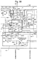
- Figure 1 is a schematic block diagram of a dental scaler system in accordance with the invention.
- Figure 1 is broken into Figure 1A, Figure 1B and Figure 1C which form Figure 1 by positioning Figure 1B in the center with Figure 1A to the left of Figure 1B and positioning Figure 1C to the right of Figure 1B.
- Figure 2 is a circuit diagram of the dental scaler system shown in Figure 1.
- Figure 2 is broken into Figures 2A and 2B which form Figure 2 by positioning Figure 2A to the left and Figure 2B to the right.
- Figure 3 is a circuit diagram of the portion of dental scaler system shown in Figure 1.
- Figure 3 is broken into Figure 3A, Figure 3B and Figure 3C which form Figure 3 by positioning Figure 3B in the center with Figure 3A to the left of Figure 3B and positioning Figure 3C to the right of Figure 3B.
- Figure 4 shows a typical transfer function for feedback voltage and handpiece drive voltage.
- the invention provides a method of operating a dental scaler system having a vibrating scaling tip by continuously monitoring the amplitude and frequency of vibration of the tip which provides scaling power to a tooth in a patient's mouth.
- the amplitude and frequency of vibration of the tip is continuously adjusted in response to external conditions to maintain a substantially constant tip motion.
- the tip is vibrated at its resonant frequency and the system provides a substantially constant scaling action while the user varies the applied pressure of the tip against the tooth.
- the dental scaler is excited (actuated) through the actions of a magnetostrictive transducer; a drive coil; a buck coil; and a feedback coil. Vibration of the magnetostrictive transducer induces a magnetostrictive characteristic signal in the feedback coil.
- Applying a drive signal to the drive coil causes the transducer to vibrate in response to the drive signal.
- the feedback signal is proportional in amplitude and phase to both the drive signal and the magnetostrictive characteristic signal.
- an amplitude comparison is provided.
- a phase comparison is provided and used to control the drive signal frequency in response to the phase comparison.
- Dental scaling system 100 includes voltage controlled oscillator 1, pulse width modulator 2, drive stage and tuner 3, transducer 4, attenuator and zero crossing detectors 5 and 6, time delay 7, phase detector 8, filter 9, U/S enable 10, slope amplifier 11, integrator 12, peak detector and attenuator 13, boost enable 14 and variable resistance element 15.
- Voltage controlled oscillator 1 is connected through electrical conductor 61 to pulse width modulator 2.
- Pulse width modulator 2 is connected through electrical conductor 62 to driver stage and tuning 3.
- Driver stage and tuning 3 is connected through electrical conductor 63 to transducer 4.
- Attenuator 5 is connected through electrical conductor 65 to phase detector 8.
- Attenuator 6 is connected through electrical conductor 66 to time delay 7.
- Time delay 7 is connected through electrical conductor 67 to phase detector 8.
- Phase detector 8 is connected through electrical conductor 68 to low pass filter 9.
- Low pass filter 9 is connected through electrical conductor 69 to voltage control oscillator 1.
- U/S enable 10 is connected through electrical conductor 110 to driver stage and tuning 3.
- Dual slope amplifier and amplitude conditioner 11 is connected through electrical conductor 71 to difference and integrator 12.
- Difference and integrator 12 is connected through electrical conductor 72 to pulse width modulator 2.
- Peak detector and attenuator 13 is connected through electrical conductor 73 to difference and integrator 12.
- Boost enable 14 is connected through electrical conductor 74 to dual slope amplifier amplitude conditioner 11.
- a power control 15 is connected through electrical conductor 75 to dual slope amplifier amplitude conditioner 11.
- Foot switch 20 is connected through electrical conductor 80 to U/S enable 10.
- Foot switch 22 is connected through electrical conductor 82 to boost enable 14.
- Attenuator 6 is connected through electrical conductor 76 to transducer 4.
- Transducer 4 includes ultrasonic tip 52, and coils 54, 56, and 58.
- phase lock loop 680 is an integrated circuit (I.C.) device which includes oscillator 359 and phase comparator 430 as shown in Figure 3.
- Oscillator 359 is connected to capacitor 360 through electrical conductors 360C an 360CC.
- Phase lock loop integrated circuit 680 is connected by electrical conductors to capacitor 432 and resistor 362.
- Pulse width modulator 2 includes comparator 366 and resistors 367, 368, 369, 370 and 371 as shown in Figure 3.
- Comparator 366 is connected to resistors 367 and 369 through conductors 367C and 369C respectively.
- Resistor 369 is connected to resistors 368 and 307 through conductors 368C and 370C.
- Resistor 370 is connected to resistor 371 through electrical conductor 371C.
- Driver stage and tuning 3 include sink and power amplifier 375, capacitor 376, resistor 377, transistor 378, resistor 379, variable resistor 380, transistor 381, resistor 382, capacitor 383, inductor 384, solenoid 385, capacitor 390, resistor 391 and diode 392 as shown in Figure 2.
- Amplifier 375 is connected to capacitor 376, resistor 377, diode 372 and transistor 378 by electrical conductors 376C, 376CC, 377C, 378C and 392C as shown in Figure 2.
- Transistor 378 is connected to resistor 379 through electrical conductor 379C.
- Resistor 379 is connected to variable resistor 380 through electrical conductor 380C.
- Variable conductor 380 is connected to transistor 381 through electrical conductor 381C.
- Transistor 381 is connected through electrical conductor 382C to resistor 382.
- Diode 392 is connected to capacitor 390 through electrical conductor 390C.
- Diode 392 is connected to resistor 391 to electrical 391C.
- Diode 392 is connected to solenoid 385 through electrical conductor 385C.
- Handpiece 4 includes drive coil 54, connector 355, feed back coil 58 and bucking coil 56 as shown in Figure 2.
- Coil 54 is connected to connector 355 through electrical conductor 355C.
- Coil 54 is connected to coil 56 through electrical conductor 354C.
- Coil 56 is connected to connector 355 through electrical conductor 56C.
- Coil 58 is connected to switch 355C through electrical conductor 58C and 58CC.
- Attenuator and zero crossing detector 5 includes comparator 390, capacitor 391, resistor 390R, resistor 392, resistor 393 and resistor 394 as shown in Figure 3.
- Comparator 390 is connected to capacitor 391, and resistors 390R, 392, 393 and 394 by electrical conductors 390C, 391C, 392C, 393C and 394C respectively as shown in Figure 3.
- Attenuator and zero crossing detector 6 includes comparator 396, resistor 397, resistor 398, resistor 399, resistor 400 and resistor 401 as shown in Figure 3.
- Comparator 396 is connected to resistors 397, 398, 399 and 400 by electrical conductors 397C, 398C, 399C and 400C respectively.
- Resistors 400 is connected to resistor 401 by electrical conductor 401C.
- Time delay 7 includes non-retrigerable, monostable multivibrator I.C. device 410, capacitor 412, resistor 414, capacitor 416, capacitor 420 and resistor 418 as shown in Figure 3.
- Multivibrator 410 is connected to capacitor 412 by electrical conductors 412C and 412CC.
- Multivibrator 410 is connected to resistor 414 through electrical conductor 414C.
- Multivibrator 410 is connected to capacitor 416 through electrical conductors 416C and 416CC.
- Multivibrator 410 is connected to capacitor 420 though electrical conductors 420C and 420CC.
- Capacitor 420 is connected to resistor 418 through electrical 418C.
- Phase detector 8 includes comparator 430 and capacitor 432, as shown in Figure 3.
- Low pass filter 9 includes capacitor 438 and resistor 440, as shown in Figure 3. Capacitor 438 is connected to resistor 440 by electrical conductor 438C.
- U/S enable 10 includes amplifiers 444 and 446, transistors 448 and 450 as shown in Figure 3.
- Amplifier 444 is connected to resistors 452, 454, 458 and 460 by electrical conductor lines 452C, 454C, 458C and 460C.
- Amplifier 444 is connected to capacitor 456 by electrical conductor line 456C.
- Resistor 460 is connected to diode 462 by electrical conductor 462C.
- Amplifier 446 is connected to capacitor 464 and resistor 466 by electrical conductors 464C and 466C.
- Transistor 448 is connected resistor 468, resistor 470 and capacitor 472 by electrical conductors 468C, 470C and 472C.
- Transistor 448 is connected to resistor 392 by electrical conductor 392C.
- Transistor 450 is connected to resistor 474 by electrical conductor 474C, as shown in Figure 3.
- Dual slope amplifier 11 includes amplifiers 480 and 482 as shown in Figure 2.
- Amplifier 480 is connected to resistors 484, 486, 488 and 490 by electrical conductors 484C, 486C, 486CC, 488C and 490C.
- Resistor 488 is connected to resistors 492 and 494 and to diode 496 by electrical conductors 492C, 494C and 496C respectively.
- Diode 496 is connected to resistors 498 by electrical conductor 498C.
- Amplifier 482 is connected to capacitors 500, 502 and 504 and resistors 506 and 508 by electrical conductors 500C, 502C, 504C, 504CC, 506C and 508C respectively.
- Resistor 508 is connected to resistors 510 and 512 by electrical conductors 510C and 512C, as shown in Figure 2.
- Difference and integrator 12 includes amplifier 520 and transistor 522, as shown in Figure 3.
- Amplifier 520 is connected to resistors 524 and 526 and capacitors 528 and 530 and diode 532 by electrical conductors 524C, 526C, 528C, 528CC, 530C and 532C respectively.
- Transistor 522 is connected to resistors 534 and 536 by electrical conductors 534C and 536C.
- Resistor 527 is connected to resistor 538 by electrical conductor 527C.
- Resistor 538 is connected to resistors 540 and 542 by electrical conductors 540C and 542C respectively.
- Peak detector 13 includes amplifier 550 as shown in Figure 3.
- Amplifier 550 is connected to resistor 552, 554, 556 and 558 by electrical conductors 552C, 554C, 556C and 558C.
- Resistor 558 is connected to capacitor 560 and diode 562 by electrical conductors 560C and 562C.
- Diode 562 is connected to resistors 564 and 566 by electrical conductors 564C and 566C, as shown in Figure 3.
- Boost enable 14 includes amplifier 570, as shown in Figure 3.
- Amplifier 570 is connected to capacitor 572, resistor 574 and resistor 576 by electrical conductors 521C, 514C and 576C.
- the scaler system of the invention includes two closed loops.
- One of the closed loops is configured to provide automatic tuning. That is, frequency of operation is automatically tuned to be at or near resonance of a particular insert.
- Transducer 4 includes drive coil winding 54, buck coil winding 56 and feedback coil winding 58. Transducer 4 also includes transducer tip 52.
- the driving coil provides a field that causes the transducer to vibrate.
- the buck coil effectively cancels the driving field over that portion of the transducer where the feedback winding coil is positioned.
- the vibrating transducer generates its own magnetic field.
- the feedback winding picks up the magnetic field generated by the transducer vibration and converts it into the feedback voltage.
- the feedback voltage generated is directly portional to insert vibration.
- Figure 4 shows a typical transfer function for feedback voltage and handpiece drive voltage. At resonance, the ratio of feedback voltage to handpiece voltage is maximum. There is also a phase delay of about 90° between the two signals. This relationship is utilized in the invention to maintain the frequency of operation of the scaling tip at or near resonance.
- Handpiece drive voltage is applied to attenuator 6 through line 76 from drive coil 54.
- Attenuator 6 is preferably a zero crossing detector (comparator) which in turn provides switching signal. This signal is delayed in time through time delay 7.
- Time delay 7 is preferably a non-retrigerable monostable multivibrator. This time delay corresponds to a 90° phase lag over the particular frequency range of the 30K insert.
- An output signal is transferred from time delay 7 through electrical conductor 67 to phase detector 8.
- Phase detector 8 receives an input signal from attenuator 5 through line 65.
- Attenuator 5 receives a signal from feedback coil 58 through electrical conductor 130.
- Low pass filter 9 receives a signal from phase detector 8 through electrical conductor 68.
- Low pass filter 9 is a resistance capacitance network which generates a direct current voltage that is proportional to the phase difference between the two inputs. This voltage is then applied to the voltage controlled oscillator 1.
- the voltage controlled oscillator 1 generates a frequency proportional to the DC voltage input that drives the pulse width modulation circuit 2.
- Pulse width modulator 2 sends an output signal through electrical conductor 62 to driver stage and tuning network 3.
- Driver stage and tuning network 3 transmits the handpiece voltage drive signal to the drive coil 54 through electrical conductor 63.
- Phase Lock is obtained by initially running the voltage controlled oscillator 1 below the resonant frequency of any insert. Typically operating the voltage oscillator 1 below a frequency of 25kHz with the low pass filter 9 providing zero volts DC is sufficient to cover the resonant frequency range of applicable inserts.
- the initial frequency of 25kHz is applied to the transducer.
- the generated handpiece voltage drive signal and, in turn, the feedback voltage signal drive the phase detector 8.
- the phase detector generates an error voltage which charges the low pass filter to a new D.C. level which is greater than zero volts.
- the voltage controlled oscillator starts to increase in frequency. This change in frequency will stop only when the phase detector reaches 0° phase shift between its two inputs. But because of our time delay, which represents a 90° phase shift in the handpiece drive signal, 0° phase shift for phase detector inputs will happen when feedback voltage and handpiece voltage drive signals have 90° phase shift between them. But, from Figure 4 we see that this 90° phase shift between the two signals occurs at the resonance condition.
- Utilizing the handpiece voltage drive and the feedback voltage signal directly from the transducer provides unexpectedly superior maintenance of resonance conditions.
- the invention provides extremely low stroke operation for subgingival applications while maintaining resonant frequency. It is unnecessary to manually detune the system to obtain very low strokes.
- the handpiece has a drive coil, a buck coil and a feedback coil for the acceptance of and generation of electrical signals utilized in conjunction with a magnetostrictive transducer and associated control circuitry.
- the feedback coil generates an electronic signal, the feedback signal, that is proportional in amplitude and phase to both the electronic signal applied to the drive coil, the drive signal, and the magnetostrictive transducer characteristics. Affects of variations in transducer characteristics due to external conditions are minimized since a direct comparison of feedback signal amplitude and phase characteristics at the handpiece are utilized in the control circuitry.
- the feedback signal phase variation relative to the drive signal phase is used in conjunction with a phase lock loop circuit to maintain a nearly constant 90° phase shift between the two signals forcing the frequency of operation to track the resonance of the magnetostrictive transducer for optimum vibration under varying external conditions.
- the feedback signal amplitude variation relative to a user commanded input signal is used in conjunction with a feedback control circuit to set, and continuously maintain nearly constant, the amplitude of vibration of the magnetostrictive transducer for optimum performance under varying external conditions.
- the transducer's amplitude of vibration is controlled by pulse-width modulating the power amplifier stage thereby controlling the drive signal's duty cycle and, as a result, the average power applied to the handpiece.
- Pulse-width modulation is preferably implemented in the power amplifier utilizing a power MOS-FET device or a bipolar Darlington device.
- An alternate implementation for continuously controlling the transducer's amplitude of vibration is by amplitude modulating the power amplifier stage thereby controlling the drive signal's amplitude and, as a result, the average power applied to the handpiece.
- the use commanded input signal is processed through a dual-slope amplifier and amplitude conditioner that allows the feedback control system to operate properly with a range of magnetostrictive transducers possessing feedback signal sensitivities on the order of two to one.
- the dual-slope amplifier and amplitude conditioner ameliorates the difference between transducer types to provide better overall resolution and close upper end performance.
Description
Claims (13)
- A method of continuous control of tip vibration in a dental scaler system comprising:providing a dental scaler havinga magnetostrictive transducer (4) having a tip (52);a drive coil (54);a buck coil (56); anda feedback coil (58);said magnetostrictive transducer (4) having a magnetostrictive characteristic signal,applying a drive signal to said drive coil (54) in response to a user commanded input signal, said drive signal inducing a feedback signal and a magnetostrictive characteristic signal in response to said drive signal, said feedback signal being proportional in amplitude and phase to said drive signal, said magnetostrictive characteristic signal being proportional in amplitude and phase to said drive signal,comparing said feedback signal amplitude to said user commanded input signal amplitude to provide an amplitude comparison,controlling said drive signal amplitude in response to said amplitude comparison,comparing said feedback signal phase with said drive signal phase, to provide a phase comparison,controlling said drive signal frequency in response to said phase comparison.
- The method of claim 1 wherein said feedback signal has a phase variation relative to said drive signal of between 85° and 95° of phase shift at resonance, said feedback signal phase variation being maintained by a phase locked loop, whereby the frequency of the vibration of said magnetostrictive transducer (4) is maintained substantially at the resonant frequency of said magnetostrictive transducer.
- The method of claim 1 wherein said feedback signal has an amplitude variation when compared to a controlling input signal and said amplitude variation is fed to a feedback control circuit.
- The method of claim 1 wherein said dental scaler further comprises a power amplifier (375).
- The method of claim 4 wherein said dental scaler further comprises a pulse width modulator (2) for pulse width modulating the power amplifier signal from said power amplifier (375) within a closed loop circuit, said pulse width modulator (2) being connected to conduct said pulse width modified signal to said drive coil.
- The method of claim 5 wherein said pulse width modulator (2) comprises a power MOS-FET device.
- The method of claim 5 wherein said pulse width modulator (2) comprises amplitude modulating a bipolar Darlington device.
- The method of claim 1 wherein said dental scaler further comprises a dual slope amplifier and amplitude conditioner (11).
- The method of claim 1 further comprising applying a varying load force to the insert tip (52) that affects tip motion and the magnetostrictive characteristic signal, said change in magnetostrictive characteristic signal being reflected in a proportional change in the feedback signal, said change in feedback signal being reflected in a proportional change in the drive signal that acts in a direction to cancel said change in tip motion.
- The method of claim 1 wherein said dental scaler further comprises a footswitch, said footswitch having a first and second position contacts (20, 22).
- The method of claim 10 wherein said second position provides a momentary boost in amplitude of vibration without requiring operator to leave operating field physically or visually.
- The method of claim 1 wherein said dental scaler comprises and increases range of amplitude of vibration, particularly very low levels, without tuning off resonance.
- The method of claim 1 wherein said magnetostrictive characteristic signal being proportional in amplitude and phase to external forces exerted on said tip.
Applications Claiming Priority (3)
| Application Number | Priority Date | Filing Date | Title |
|---|---|---|---|
| US08/715,663 US5754016A (en) | 1996-09-18 | 1996-09-18 | Method of continuous control of tip vibration in a dental scalar system |
| US715663 | 1996-09-18 | ||
| PCT/US1997/015304 WO1998011844A1 (en) | 1996-09-18 | 1997-09-08 | Method of continuous control of tip vibration in a dental scalar system |
Publications (2)
| Publication Number | Publication Date |
|---|---|
| EP0927005A1 EP0927005A1 (en) | 1999-07-07 |
| EP0927005B1 true EP0927005B1 (en) | 2001-12-05 |
Family
ID=24874983
Family Applications (1)
| Application Number | Title | Priority Date | Filing Date |
|---|---|---|---|
| EP97939689A Expired - Lifetime EP0927005B1 (en) | 1996-09-18 | 1997-09-08 | Method of continuous control of tip vibration in a dental scaler system |
Country Status (7)
| Country | Link |
|---|---|
| US (1) | US5754016A (en) |
| EP (1) | EP0927005B1 (en) |
| JP (1) | JP2001500760A (en) |
| CN (1) | CN1104226C (en) |
| DE (1) | DE69708893T2 (en) |
| ES (1) | ES2168143T3 (en) |
| WO (1) | WO1998011844A1 (en) |
Cited By (3)
| Publication number | Priority date | Publication date | Assignee | Title |
|---|---|---|---|---|
| DE102006006730A1 (en) * | 2006-02-13 | 2007-08-16 | Sirona Dental Systems Gmbh | Apparatus and method for operating an ultrasonically driven tool |
| DE102007053460A1 (en) * | 2007-11-07 | 2009-05-20 | Sirona Dental Systems Gmbh | Method for operating a dental ultrasound device and dental ultrasound device |
| DE102007055583A1 (en) * | 2007-11-20 | 2009-05-28 | Sirona Dental Systems Gmbh | Dental ultrasound instrument and method for operating a dental ultrasonic instrument |
Families Citing this family (27)
| Publication number | Priority date | Publication date | Assignee | Title |
|---|---|---|---|---|
| US6075714A (en) * | 1997-05-30 | 2000-06-13 | American Dental Technologies, Inc. | Regulated drive for vibratory feeders |
| US6619957B1 (en) | 1999-02-16 | 2003-09-16 | Dentsply Research & Development Corp. | Ultrasonic scaler |
| US6503081B1 (en) | 1999-07-01 | 2003-01-07 | James Feine | Ultrasonic control apparatus and method |
| US6450811B1 (en) | 1999-09-24 | 2002-09-17 | Dentsply Research & Development Corp. | Dental scaler system and method |
| WO2001045581A1 (en) | 1999-12-20 | 2001-06-28 | Dentsply International Inc. | Dental scaler system and method |
| EP1238715A1 (en) * | 2001-03-05 | 2002-09-11 | Prokic Miodrag | Multifrequency ultrasonic structural actuators |
| KR100418734B1 (en) * | 2001-08-21 | 2004-02-18 | 주식회사 디메텍 | Monitor apparatus and method of supersonic |
| US6918300B2 (en) * | 2002-06-24 | 2005-07-19 | Koninklijke Philips Electronics N.V. | System and method for determining the resonant frequency and/or amplitude of an oscillating appliance such as a power toothbrush |
| KR100482769B1 (en) * | 2002-09-12 | 2005-04-14 | 경원훼라이트공업 주식회사 | Ultrasonic scaler driver |
| US8295025B2 (en) * | 2005-02-23 | 2012-10-23 | Alan Edel | Apparatus and method for controlling excitation frequency of magnetostrictive ultrasonic device |
| US7614878B2 (en) * | 2005-05-18 | 2009-11-10 | Pcg, Inc. | System and method for dynamic control of ultrasonic magnetostrictive dental scaler |
| US7439463B2 (en) * | 2006-01-17 | 2008-10-21 | Dentsply International Inc. | Foot switch for activating a dental or medical treatment apparatus |
| US20070166662A1 (en) | 2006-01-17 | 2007-07-19 | Kevin Lint | Hard-wired and wireless system with footswitch for operating a dental or medical treatment apparatus |
| US7839107B2 (en) * | 2006-10-31 | 2010-11-23 | Kaltenbach & Voigt Gmbh | Method and circuitry arrangement for operating a brushless electric motor |
| WO2008061225A2 (en) * | 2006-11-16 | 2008-05-22 | Hu - Friedy Mfg. Co., Inc. | Tip - based computer controlled system for a hand-held dental delivery device |
| WO2009116994A1 (en) * | 2008-03-18 | 2009-09-24 | Hu-Friedy Mfg. Co., Inc. | Handpiece for a magnetostrictive power generator |
| JP5365277B2 (en) * | 2009-03-17 | 2013-12-11 | オムロンヘルスケア株式会社 | electric toothbrush |
| EP2284987B1 (en) * | 2009-08-12 | 2019-02-06 | Braun GmbH | Method and device for adjusting the frequency of a drive current of an electric motor |
| US9463077B2 (en) * | 2009-10-16 | 2016-10-11 | Dentsply International Inc. | Dental scaler |
| DE102009055197A1 (en) * | 2009-12-22 | 2011-06-30 | Sirona Dental Systems GmbH, 64625 | Method for automatic determination of operating states of a dental ultrasound device |
| US9018887B2 (en) | 2010-04-01 | 2015-04-28 | Westdale Holdings, Inc. | Ultrasonic system controls, tool recognition means and feedback methods |
| EP2571444B1 (en) | 2010-04-12 | 2018-07-04 | DENTSPLY SIRONA Inc. | Method of selectively pairing wireless controller to multiple dental/medical instruments |
| US10020679B2 (en) | 2011-04-29 | 2018-07-10 | James Feine | Handheld electrical device system and method |
| US9050161B2 (en) | 2011-04-29 | 2015-06-09 | James S. Feine | Energy harvesting insert for an ultrasonic handpiece with electrical device |
| US9131996B2 (en) | 2011-11-14 | 2015-09-15 | Coltene Whaledent, Inc. | Dental scaler |
| US9504471B2 (en) * | 2013-09-25 | 2016-11-29 | Cybersonics, Inc. | Ultrasonic generator systems and methods |
| CN108245270A (en) * | 2017-12-29 | 2018-07-06 | 宁夏软件工程院有限公司 | A kind of fast reaction electric toothbrush of brain wave control |
Family Cites Families (58)
| Publication number | Priority date | Publication date | Assignee | Title |
|---|---|---|---|---|
| US2947082A (en) * | 1953-05-15 | 1960-08-02 | Epstein Herman | Crystal driven dental tool |
| US3067765A (en) * | 1961-08-02 | 1962-12-11 | We Mar Inc | Foot control valve assembly for dental handpieces |
| US3414000A (en) * | 1966-08-24 | 1968-12-03 | Univ Loma Linda | Flow control unit |
| SE339346B (en) * | 1969-03-12 | 1971-10-04 | Amlab Ab | |
| US3727112A (en) * | 1969-08-29 | 1973-04-10 | Surgical Design Corp | Generator for producing ultrasonic energy |
| US3924335A (en) * | 1971-02-26 | 1975-12-09 | Ultrasonic Systems | Ultrasonic dental and other instrument means and methods |
| US3809977A (en) * | 1971-02-26 | 1974-05-07 | Ultrasonic Systems | Ultrasonic kits and motor systems |
| DE2338636B2 (en) * | 1973-07-30 | 1978-01-05 | Ritter Ag, 7500 Karlsruhe | ARRANGEMENT FOR THE AUTOMATIC, ELECTRONIC SPEED AND TORQUE CONTROL OF A COMPRESSED GAS MANUAL, IN PARTICULAR FOR THE DENTAL AREA |
| DE2339827B2 (en) * | 1973-08-06 | 1977-02-24 | A6 In 3-02 | DENTAL EQUIPMENT |
| GB1433978A (en) * | 1973-12-04 | 1976-04-28 | Kaltenbach & Voigt | Electronic control unit for an oscillatory dental instrument |
| DE2417890C3 (en) * | 1974-04-11 | 1985-03-14 | Siemens AG, 1000 Berlin und 8000 München | Dental facility |
| DE2459841B2 (en) * | 1974-12-18 | 1976-10-14 | Litton Industries, Inc., Beverly Hills, Calif. (V.StA.) | ELECTRICAL DRIVE AND CONTROL DEVICE FOR DENTAL TREATMENT DEVICES WITH ULTRASONIC |
| DE2530108C3 (en) * | 1975-07-05 | 1980-07-10 | Emda Fabrik Elektro-Medizinischer Und Dentaler Apparate Georg Hartmann Gmbh & Co Kg, 6000 Frankfurt | Control device for dental treatment devices with a foot switch arrangement |
| BR7608703A (en) * | 1975-12-30 | 1977-10-25 | Litton Industries Inc | ELECTRIC CONTROL AND CONTROL CIRCUIT FOR ULTRASONIC DENTAL TREATMENT DEVICES |
| US4041609A (en) * | 1976-05-21 | 1977-08-16 | Dentsply Research & Development Corporation | Foot control for dental equipment |
| DE2710049C2 (en) * | 1977-03-08 | 1985-03-07 | MEDTRONIC medizinisch-elektronische Gerätegesellschaft mbH, 6390 Usingen | Ultrasonic dental treatment device |
| DE3114023C2 (en) * | 1981-04-07 | 1984-04-26 | Kaltenbach & Voigt Gmbh & Co, 7950 Biberach | Dental treatment place |
| IT1091427B (en) * | 1977-09-22 | 1985-07-06 | Neri Vincenzo | SYSTEM FOR THE CONTROL OF THE AIR SUPPLY IN PRESSURE AND WATER TO THE HANDPIECES FOR DENTAL USE |
| US4403176A (en) * | 1978-05-08 | 1983-09-06 | California Technics, Ltd. | Circuit for driving an ultrasonic dental tool at its resonant frequency |
| JPS54147691A (en) * | 1978-05-08 | 1979-11-19 | Litton Industries Inc | Drive circuit of ultrasoniccwave dental appliance |
| US4428748A (en) * | 1980-04-09 | 1984-01-31 | Peyman Gholam A | Combined ultrasonic emulsifier and mechanical cutter for surgery |
| US4479098A (en) * | 1981-07-06 | 1984-10-23 | Watson Industries, Inc. | Circuit for tracking and maintaining drive of actuator/mass at resonance |
| DE3136028C2 (en) * | 1981-09-11 | 1986-12-18 | Hartmut Dipl.-Ing. 7504 Weingarten Teichmann | Circuit arrangement for a magnetostrictive ultrasonic transducer |
| US4445063A (en) * | 1982-07-26 | 1984-04-24 | Solid State Systems, Corporation | Energizing circuit for ultrasonic transducer |
| DE3302389A1 (en) * | 1983-01-25 | 1984-07-26 | Kaltenbach & Voigt Gmbh & Co, 7950 Biberach | CIRCUIT FOR CONTROLLING ACTUATORS OF A DENTAL TREATMENT STATION |
| DE3302558A1 (en) * | 1983-01-26 | 1984-07-26 | Kaltenbach & Voigt Gmbh & Co, 7950 Biberach | FOOT CONTROL DEVICE, IN PARTICULAR FOR DENTAL APPARATUS |
| DE3378401D1 (en) * | 1983-04-04 | 1988-12-15 | Sumitomo Bakelite Co | Ultrasonic oscillator |
| DK517483D0 (en) * | 1983-11-11 | 1983-11-11 | Sven Karl Lennart Goof | TOUCH SENSOR |
| US4676750A (en) * | 1985-01-25 | 1987-06-30 | Mason Michael S | Dental drill system |
| SE461010B (en) * | 1985-11-08 | 1989-12-18 | Swedemed Ab | DEVICE FOR ULTRA SOUND KNIFE |
| US4768496A (en) * | 1986-04-09 | 1988-09-06 | Cooper Lasersonics, Inc. | Handpiece interlock and logic control for ultrasonic surgical system |
| US4878841A (en) * | 1986-06-19 | 1989-11-07 | Mcculloch Christopher A G | Periodontal probe |
| SU1457913A1 (en) * | 1987-01-07 | 1989-02-15 | Всесоюзный Научно-Исследовательский Институт Медицинского Приборостроения | Pedal for stomatological apparatus |
| US4820152A (en) * | 1987-04-21 | 1989-04-11 | Dentsply Research & Development Corp. | Single multi-function handpiece for dental instruments |
| EP0287693A1 (en) * | 1987-04-22 | 1988-10-26 | Nakanishi Dental Mfg. Co. Ltd. | Apparatus for dental treatment provided with check valve in fluid passage |
| CH673387A5 (en) * | 1987-08-25 | 1990-03-15 | Bien Air | |
| US4966131A (en) * | 1988-02-09 | 1990-10-30 | Mettler Electronics Corp. | Ultrasound power generating system with sampled-data frequency control |
| US5419703A (en) * | 1988-02-18 | 1995-05-30 | Dentsply Research & Development Corp. | Method of subgingival scaling and lavage |
| DE3817347A1 (en) * | 1988-05-20 | 1989-11-23 | Zubler Geraetebau | Operating device for hand-guided grinding apparatuses |
| US5033238A (en) * | 1988-05-20 | 1991-07-23 | Kurt Zubler | Dental technician's work station |
| US4965532A (en) * | 1988-06-17 | 1990-10-23 | Olympus Optical Co., Ltd. | Circuit for driving ultrasonic transducer |
| DE3900601A1 (en) * | 1989-01-11 | 1990-08-02 | Emda | Method of adjusting the speed of rotation |
| US5180363A (en) * | 1989-04-27 | 1993-01-19 | Sumitomo Bakelite Company Company Limited | Operation device |
| US5151085A (en) * | 1989-04-28 | 1992-09-29 | Olympus Optical Co., Ltd. | Apparatus for generating ultrasonic oscillation |
| US5139509A (en) * | 1989-08-25 | 1992-08-18 | Site Microsurgical Systems, Inc. | Phacoemulsification system with handpiece simulator |
| EP0424685B1 (en) * | 1989-10-27 | 1995-05-10 | Storz Instrument Company | Method for driving an ultrasonic transducer |
| US5026387A (en) * | 1990-03-12 | 1991-06-25 | Ultracision Inc. | Method and apparatus for ultrasonic surgical cutting and hemostatis |
| US5106302A (en) * | 1990-09-26 | 1992-04-21 | Ormco Corporation | Method of fracturing interfaces with an ultrasonic tool |
| US5320532A (en) * | 1990-09-26 | 1994-06-14 | Ormco Corporation | Method of using ultrasonic dental tool |
| US5130619A (en) * | 1990-12-26 | 1992-07-14 | Kubota Corporation | Drive control apparatus for an ultrasonic motor |
| US5184605A (en) * | 1991-01-31 | 1993-02-09 | Excel Tech Ltd. | Therapeutic ultrasound generator with radiation dose control |
| DE4125313A1 (en) * | 1991-07-31 | 1993-02-04 | Ritter Gmbh Dentaleinrichtung | METHOD FOR CONTROLLING A DENTAL TREATMENT DEVICE AND A DENTAL TREATMENT DEVICE |
| JP3184884B2 (en) * | 1991-12-02 | 2001-07-09 | 和子 姫野 | Ultrasonic grinding machine |
| ES2104953T3 (en) * | 1992-02-07 | 1997-10-16 | Valleylab Inc | SURGICAL DEVICE ULTRASONIC. |
| DK170483B1 (en) * | 1992-11-18 | 1995-09-18 | Flex Dental As | Microprocessor controlled dentist with selectable instrument control functions |
| DE69331343T2 (en) * | 1992-11-30 | 2002-08-22 | Sherwood Serv Ag | CIRCUIT FOR AN ULTRASONIC SURGICAL INSTRUMENT WITH AN ENERGY INITIATOR FOR MAINTAINING VIBRATIONS AND LINEAR DYNAMICS |
| US5451161A (en) * | 1993-08-24 | 1995-09-19 | Parkell Products, Inc. | Oscillating circuit for ultrasonic dental scaler |
| DE69534254T2 (en) * | 1994-01-28 | 2005-10-27 | Advanced Medical Optics, Inc., Santa Ana | Apparatus for controlling the purging and aspiration of fluids during ophthalmic surgery |
-
1996
- 1996-09-18 US US08/715,663 patent/US5754016A/en not_active Expired - Lifetime
-
1997
- 1997-09-08 EP EP97939689A patent/EP0927005B1/en not_active Expired - Lifetime
- 1997-09-08 DE DE69708893T patent/DE69708893T2/en not_active Expired - Lifetime
- 1997-09-08 CN CN97193962A patent/CN1104226C/en not_active Expired - Lifetime
- 1997-09-08 JP JP10514683A patent/JP2001500760A/en active Pending
- 1997-09-08 ES ES97939689T patent/ES2168143T3/en not_active Expired - Lifetime
- 1997-09-08 WO PCT/US1997/015304 patent/WO1998011844A1/en active IP Right Grant
Cited By (5)
| Publication number | Priority date | Publication date | Assignee | Title |
|---|---|---|---|---|
| DE102006006730A1 (en) * | 2006-02-13 | 2007-08-16 | Sirona Dental Systems Gmbh | Apparatus and method for operating an ultrasonically driven tool |
| DE102006006730B4 (en) * | 2006-02-13 | 2008-01-03 | Sirona Dental Systems Gmbh | Apparatus and method for operating an ultrasonically driven tool |
| DE102007053460A1 (en) * | 2007-11-07 | 2009-05-20 | Sirona Dental Systems Gmbh | Method for operating a dental ultrasound device and dental ultrasound device |
| DE102007053460B4 (en) * | 2007-11-07 | 2014-10-16 | Sirona Dental Systems Gmbh | Method for operating a dental ultrasound device and dental ultrasound device |
| DE102007055583A1 (en) * | 2007-11-20 | 2009-05-28 | Sirona Dental Systems Gmbh | Dental ultrasound instrument and method for operating a dental ultrasonic instrument |
Also Published As
| Publication number | Publication date |
|---|---|
| US5754016A (en) | 1998-05-19 |
| JP2001500760A (en) | 2001-01-23 |
| WO1998011844A1 (en) | 1998-03-26 |
| ES2168143T3 (en) | 2002-06-01 |
| EP0927005A1 (en) | 1999-07-07 |
| DE69708893T2 (en) | 2002-06-20 |
| CN1216455A (en) | 1999-05-12 |
| CN1104226C (en) | 2003-04-02 |
| DE69708893D1 (en) | 2002-01-17 |
Similar Documents
| Publication | Publication Date | Title |
|---|---|---|
| EP0927005B1 (en) | Method of continuous control of tip vibration in a dental scaler system | |
| US5730594A (en) | Ultrasonic dental scaler selectively tunable either manually or automatically | |
| US8295025B2 (en) | Apparatus and method for controlling excitation frequency of magnetostrictive ultrasonic device | |
| US5451161A (en) | Oscillating circuit for ultrasonic dental scaler | |
| CA2271304C (en) | System and method for tuning and controlling an ultrasonic handpiece | |
| US6274963B1 (en) | Methods and devices for controlling the vibration of ultrasonic transmission components | |
| US6391042B1 (en) | Pulsed ultrasonic device and method | |
| US4445063A (en) | Energizing circuit for ultrasonic transducer | |
| CA2139472C (en) | Method and apparatus for operating a generator supplying a high-frequency power to an ultrasonic transducer | |
| US7485106B2 (en) | Micro-burst ultrasonic power delivery | |
| US20030222535A1 (en) | Ultrasonic driver | |
| EP0454188B1 (en) | Switching circuit in a dental handpiece | |
| US6073050A (en) | Efficient integrated RF telemetry transmitter for use with implantable device | |
| US20060269900A1 (en) | System and method for dynamic control of ultrasonic magnetostrictive dental scaler | |
| US20060287599A1 (en) | Pulsed ultrasonic device and method | |
| CA2014376A1 (en) | Ultrasonic power supply | |
| JPH0365277A (en) | Ultrasonic generator with piezoelectric convertor | |
| US3931533A (en) | Ultrasonic signal generator | |
| US4562561A (en) | Ultrasonic pest repeller | |
| CA2305297A1 (en) | Control system for a phacoemulsification handpiece | |
| US20060188841A1 (en) | Apparatus and method for controlling excitation frequency of magnetostrictive transducer | |
| JP2874833B2 (en) | Method and apparatus for safe vibration of ultrasonic decomposer | |
| US5095890A (en) | Method for sampled data frequency control of an ultrasound power generating system | |
| US6241520B1 (en) | Ultrasonic scaler with adaptive amplitude | |
| CA2247382C (en) | Method of continuous control of tip vibration in a dental scalar system |
Legal Events
| Date | Code | Title | Description |
|---|---|---|---|
| PUAI | Public reference made under article 153(3) epc to a published international application that has entered the european phase |
Free format text: ORIGINAL CODE: 0009012 |
|
| 17P | Request for examination filed |
Effective date: 19980819 |
|
| AK | Designated contracting states |
Kind code of ref document: A1 Designated state(s): CH DE ES FR GB IT LI |
|
| 17Q | First examination report despatched |
Effective date: 19991222 |
|
| RTI1 | Title (correction) |
Free format text: METHOD OF CONTINUOUS CONTROL OF TIP VIBRATION IN A DENTAL SCALER SYSTEM |
|
| GRAG | Despatch of communication of intention to grant |
Free format text: ORIGINAL CODE: EPIDOS AGRA |
|
| RTI1 | Title (correction) |
Free format text: METHOD OF CONTINUOUS CONTROL OF TIP VIBRATION IN A DENTAL SCALER SYSTEM |
|
| GRAG | Despatch of communication of intention to grant |
Free format text: ORIGINAL CODE: EPIDOS AGRA |
|
| GRAH | Despatch of communication of intention to grant a patent |
Free format text: ORIGINAL CODE: EPIDOS IGRA |
|
| GRAH | Despatch of communication of intention to grant a patent |
Free format text: ORIGINAL CODE: EPIDOS IGRA |
|
| GRAA | (expected) grant |
Free format text: ORIGINAL CODE: 0009210 |
|
| AK | Designated contracting states |
Kind code of ref document: B1 Designated state(s): CH DE ES FR GB IT LI |
|
| RTI1 | Title (correction) |
Free format text: METHOD OF CONTINUOUS CONTROL OF TIP VIBRATION IN A DENTAL SCALER SYSTEM |
|
| REG | Reference to a national code |
Ref country code: CH Ref legal event code: NV Representative=s name: E. BLUM & CO. PATENTANWAELTE Ref country code: CH Ref legal event code: EP |
|
| REG | Reference to a national code |
Ref country code: GB Ref legal event code: IF02 |
|
| REF | Corresponds to: |
Ref document number: 69708893 Country of ref document: DE Date of ref document: 20020117 |
|
| ET | Fr: translation filed | ||
| REG | Reference to a national code |
Ref country code: ES Ref legal event code: FG2A Ref document number: 2168143 Country of ref document: ES Kind code of ref document: T3 |
|
| PLBE | No opposition filed within time limit |
Free format text: ORIGINAL CODE: 0009261 |
|
| STAA | Information on the status of an ep patent application or granted ep patent |
Free format text: STATUS: NO OPPOSITION FILED WITHIN TIME LIMIT |
|
| 26N | No opposition filed | ||
| REG | Reference to a national code |
Ref country code: CH Ref legal event code: PFA Owner name: DENTSPLY INTERNATIONAL, INC. Free format text: DENTSPLY INTERNATIONAL, INC.#570 WEST COLLEGE AVENUE, P.O. BOX 872#YORK, PA 17405-0872 (US) -TRANSFER TO- DENTSPLY INTERNATIONAL, INC.#570 WEST COLLEGE AVENUE, P.O. BOX 872#YORK, PA 17405-0872 (US) |
|
| REG | Reference to a national code |
Ref country code: FR Ref legal event code: PLFP Year of fee payment: 20 |
|
| PGFP | Annual fee paid to national office [announced via postgrant information from national office to epo] |
Ref country code: DE Payment date: 20160831 Year of fee payment: 20 Ref country code: IT Payment date: 20160921 Year of fee payment: 20 Ref country code: CH Payment date: 20160914 Year of fee payment: 20 Ref country code: GB Payment date: 20160907 Year of fee payment: 20 |
|
| PGFP | Annual fee paid to national office [announced via postgrant information from national office to epo] |
Ref country code: FR Payment date: 20160816 Year of fee payment: 20 |
|
| PGFP | Annual fee paid to national office [announced via postgrant information from national office to epo] |
Ref country code: ES Payment date: 20160811 Year of fee payment: 20 |
|
| REG | Reference to a national code |
Ref country code: DE Ref legal event code: R071 Ref document number: 69708893 Country of ref document: DE |
|
| REG | Reference to a national code |
Ref country code: CH Ref legal event code: PL |
|
| REG | Reference to a national code |
Ref country code: GB Ref legal event code: PE20 Expiry date: 20170907 |
|
| PG25 | Lapsed in a contracting state [announced via postgrant information from national office to epo] |
Ref country code: GB Free format text: LAPSE BECAUSE OF EXPIRATION OF PROTECTION Effective date: 20170907 |
|
| REG | Reference to a national code |
Ref country code: ES Ref legal event code: FD2A Effective date: 20180508 |
|
| PG25 | Lapsed in a contracting state [announced via postgrant information from national office to epo] |
Ref country code: ES Free format text: LAPSE BECAUSE OF EXPIRATION OF PROTECTION Effective date: 20170909 |