EP0927547A2 - Acetabular prosthesis assembly - Google Patents
Acetabular prosthesis assembly Download PDFInfo
- Publication number
- EP0927547A2 EP0927547A2 EP98310726A EP98310726A EP0927547A2 EP 0927547 A2 EP0927547 A2 EP 0927547A2 EP 98310726 A EP98310726 A EP 98310726A EP 98310726 A EP98310726 A EP 98310726A EP 0927547 A2 EP0927547 A2 EP 0927547A2
- Authority
- EP
- European Patent Office
- Prior art keywords
- prosthesis
- liner
- shell
- component
- groove
- Prior art date
- Legal status (The legal status is an assumption and is not a legal conclusion. Google has not performed a legal analysis and makes no representation as to the accuracy of the status listed.)
- Granted
Links
Images


Classifications
-
- A—HUMAN NECESSITIES
- A61—MEDICAL OR VETERINARY SCIENCE; HYGIENE
- A61F—FILTERS IMPLANTABLE INTO BLOOD VESSELS; PROSTHESES; DEVICES PROVIDING PATENCY TO, OR PREVENTING COLLAPSING OF, TUBULAR STRUCTURES OF THE BODY, e.g. STENTS; ORTHOPAEDIC, NURSING OR CONTRACEPTIVE DEVICES; FOMENTATION; TREATMENT OR PROTECTION OF EYES OR EARS; BANDAGES, DRESSINGS OR ABSORBENT PADS; FIRST-AID KITS
- A61F2/00—Filters implantable into blood vessels; Prostheses, i.e. artificial substitutes or replacements for parts of the body; Appliances for connecting them with the body; Devices providing patency to, or preventing collapsing of, tubular structures of the body, e.g. stents
- A61F2/02—Prostheses implantable into the body
- A61F2/30—Joints
- A61F2/32—Joints for the hip
- A61F2/34—Acetabular cups
-
- A—HUMAN NECESSITIES
- A61—MEDICAL OR VETERINARY SCIENCE; HYGIENE
- A61F—FILTERS IMPLANTABLE INTO BLOOD VESSELS; PROSTHESES; DEVICES PROVIDING PATENCY TO, OR PREVENTING COLLAPSING OF, TUBULAR STRUCTURES OF THE BODY, e.g. STENTS; ORTHOPAEDIC, NURSING OR CONTRACEPTIVE DEVICES; FOMENTATION; TREATMENT OR PROTECTION OF EYES OR EARS; BANDAGES, DRESSINGS OR ABSORBENT PADS; FIRST-AID KITS
- A61F2/00—Filters implantable into blood vessels; Prostheses, i.e. artificial substitutes or replacements for parts of the body; Appliances for connecting them with the body; Devices providing patency to, or preventing collapsing of, tubular structures of the body, e.g. stents
- A61F2/02—Prostheses implantable into the body
- A61F2/30—Joints
- A61F2002/30001—Additional features of subject-matter classified in A61F2/28, A61F2/30 and subgroups thereof
- A61F2002/30316—The prosthesis having different structural features at different locations within the same prosthesis; Connections between prosthetic parts; Special structural features of bone or joint prostheses not otherwise provided for
- A61F2002/30329—Connections or couplings between prosthetic parts, e.g. between modular parts; Connecting elements
- A61F2002/30331—Connections or couplings between prosthetic parts, e.g. between modular parts; Connecting elements made by longitudinally pushing a protrusion into a complementarily-shaped recess, e.g. held by friction fit
- A61F2002/30362—Connections or couplings between prosthetic parts, e.g. between modular parts; Connecting elements made by longitudinally pushing a protrusion into a complementarily-shaped recess, e.g. held by friction fit with possibility of relative movement between the protrusion and the recess
- A61F2002/30364—Rotation about the common longitudinal axis
- A61F2002/30367—Rotation about the common longitudinal axis with additional means for preventing said rotation
-
- A—HUMAN NECESSITIES
- A61—MEDICAL OR VETERINARY SCIENCE; HYGIENE
- A61F—FILTERS IMPLANTABLE INTO BLOOD VESSELS; PROSTHESES; DEVICES PROVIDING PATENCY TO, OR PREVENTING COLLAPSING OF, TUBULAR STRUCTURES OF THE BODY, e.g. STENTS; ORTHOPAEDIC, NURSING OR CONTRACEPTIVE DEVICES; FOMENTATION; TREATMENT OR PROTECTION OF EYES OR EARS; BANDAGES, DRESSINGS OR ABSORBENT PADS; FIRST-AID KITS
- A61F2/00—Filters implantable into blood vessels; Prostheses, i.e. artificial substitutes or replacements for parts of the body; Appliances for connecting them with the body; Devices providing patency to, or preventing collapsing of, tubular structures of the body, e.g. stents
- A61F2/02—Prostheses implantable into the body
- A61F2/30—Joints
- A61F2002/30001—Additional features of subject-matter classified in A61F2/28, A61F2/30 and subgroups thereof
- A61F2002/30316—The prosthesis having different structural features at different locations within the same prosthesis; Connections between prosthetic parts; Special structural features of bone or joint prostheses not otherwise provided for
- A61F2002/30329—Connections or couplings between prosthetic parts, e.g. between modular parts; Connecting elements
- A61F2002/30383—Connections or couplings between prosthetic parts, e.g. between modular parts; Connecting elements made by laterally inserting a protrusion, e.g. a rib into a complementarily-shaped groove
- A61F2002/30403—Longitudinally-oriented cooperating ribs and grooves on mating lateral surfaces of a mainly longitudinal connection
-
- A—HUMAN NECESSITIES
- A61—MEDICAL OR VETERINARY SCIENCE; HYGIENE
- A61F—FILTERS IMPLANTABLE INTO BLOOD VESSELS; PROSTHESES; DEVICES PROVIDING PATENCY TO, OR PREVENTING COLLAPSING OF, TUBULAR STRUCTURES OF THE BODY, e.g. STENTS; ORTHOPAEDIC, NURSING OR CONTRACEPTIVE DEVICES; FOMENTATION; TREATMENT OR PROTECTION OF EYES OR EARS; BANDAGES, DRESSINGS OR ABSORBENT PADS; FIRST-AID KITS
- A61F2/00—Filters implantable into blood vessels; Prostheses, i.e. artificial substitutes or replacements for parts of the body; Appliances for connecting them with the body; Devices providing patency to, or preventing collapsing of, tubular structures of the body, e.g. stents
- A61F2/02—Prostheses implantable into the body
- A61F2/30—Joints
- A61F2002/30001—Additional features of subject-matter classified in A61F2/28, A61F2/30 and subgroups thereof
- A61F2002/30316—The prosthesis having different structural features at different locations within the same prosthesis; Connections between prosthetic parts; Special structural features of bone or joint prostheses not otherwise provided for
- A61F2002/30329—Connections or couplings between prosthetic parts, e.g. between modular parts; Connecting elements
- A61F2002/30476—Connections or couplings between prosthetic parts, e.g. between modular parts; Connecting elements locked by an additional locking mechanism
- A61F2002/30487—Circumferential cooperating grooves and beads on cooperating lateral surfaces of a mainly longitudinal connection
-
- A—HUMAN NECESSITIES
- A61—MEDICAL OR VETERINARY SCIENCE; HYGIENE
- A61F—FILTERS IMPLANTABLE INTO BLOOD VESSELS; PROSTHESES; DEVICES PROVIDING PATENCY TO, OR PREVENTING COLLAPSING OF, TUBULAR STRUCTURES OF THE BODY, e.g. STENTS; ORTHOPAEDIC, NURSING OR CONTRACEPTIVE DEVICES; FOMENTATION; TREATMENT OR PROTECTION OF EYES OR EARS; BANDAGES, DRESSINGS OR ABSORBENT PADS; FIRST-AID KITS
- A61F2/00—Filters implantable into blood vessels; Prostheses, i.e. artificial substitutes or replacements for parts of the body; Appliances for connecting them with the body; Devices providing patency to, or preventing collapsing of, tubular structures of the body, e.g. stents
- A61F2/02—Prostheses implantable into the body
- A61F2/30—Joints
- A61F2002/30001—Additional features of subject-matter classified in A61F2/28, A61F2/30 and subgroups thereof
- A61F2002/30316—The prosthesis having different structural features at different locations within the same prosthesis; Connections between prosthetic parts; Special structural features of bone or joint prostheses not otherwise provided for
- A61F2002/30329—Connections or couplings between prosthetic parts, e.g. between modular parts; Connecting elements
- A61F2002/30476—Connections or couplings between prosthetic parts, e.g. between modular parts; Connecting elements locked by an additional locking mechanism
- A61F2002/305—Snap connection
-
- A—HUMAN NECESSITIES
- A61—MEDICAL OR VETERINARY SCIENCE; HYGIENE
- A61F—FILTERS IMPLANTABLE INTO BLOOD VESSELS; PROSTHESES; DEVICES PROVIDING PATENCY TO, OR PREVENTING COLLAPSING OF, TUBULAR STRUCTURES OF THE BODY, e.g. STENTS; ORTHOPAEDIC, NURSING OR CONTRACEPTIVE DEVICES; FOMENTATION; TREATMENT OR PROTECTION OF EYES OR EARS; BANDAGES, DRESSINGS OR ABSORBENT PADS; FIRST-AID KITS
- A61F2/00—Filters implantable into blood vessels; Prostheses, i.e. artificial substitutes or replacements for parts of the body; Appliances for connecting them with the body; Devices providing patency to, or preventing collapsing of, tubular structures of the body, e.g. stents
- A61F2/02—Prostheses implantable into the body
- A61F2/30—Joints
- A61F2002/30001—Additional features of subject-matter classified in A61F2/28, A61F2/30 and subgroups thereof
- A61F2002/30316—The prosthesis having different structural features at different locations within the same prosthesis; Connections between prosthetic parts; Special structural features of bone or joint prostheses not otherwise provided for
- A61F2002/30535—Special structural features of bone or joint prostheses not otherwise provided for
- A61F2002/30537—Special structural features of bone or joint prostheses not otherwise provided for adjustable
- A61F2002/30538—Special structural features of bone or joint prostheses not otherwise provided for adjustable for adjusting angular orientation
- A61F2002/3054—Special structural features of bone or joint prostheses not otherwise provided for adjustable for adjusting angular orientation about a connection axis or implantation axis for selecting any one of a plurality of radial orientations between two modular parts, e.g. Morse taper connections, at discrete positions, angular positions or continuous positions
-
- A—HUMAN NECESSITIES
- A61—MEDICAL OR VETERINARY SCIENCE; HYGIENE
- A61F—FILTERS IMPLANTABLE INTO BLOOD VESSELS; PROSTHESES; DEVICES PROVIDING PATENCY TO, OR PREVENTING COLLAPSING OF, TUBULAR STRUCTURES OF THE BODY, e.g. STENTS; ORTHOPAEDIC, NURSING OR CONTRACEPTIVE DEVICES; FOMENTATION; TREATMENT OR PROTECTION OF EYES OR EARS; BANDAGES, DRESSINGS OR ABSORBENT PADS; FIRST-AID KITS
- A61F2/00—Filters implantable into blood vessels; Prostheses, i.e. artificial substitutes or replacements for parts of the body; Appliances for connecting them with the body; Devices providing patency to, or preventing collapsing of, tubular structures of the body, e.g. stents
- A61F2/02—Prostheses implantable into the body
- A61F2/30—Joints
- A61F2/30767—Special external or bone-contacting surface, e.g. coating for improving bone ingrowth
- A61F2/30771—Special external or bone-contacting surface, e.g. coating for improving bone ingrowth applied in original prostheses, e.g. holes or grooves
- A61F2002/30904—Special external or bone-contacting surface, e.g. coating for improving bone ingrowth applied in original prostheses, e.g. holes or grooves serrated profile, i.e. saw-toothed
-
- A—HUMAN NECESSITIES
- A61—MEDICAL OR VETERINARY SCIENCE; HYGIENE
- A61F—FILTERS IMPLANTABLE INTO BLOOD VESSELS; PROSTHESES; DEVICES PROVIDING PATENCY TO, OR PREVENTING COLLAPSING OF, TUBULAR STRUCTURES OF THE BODY, e.g. STENTS; ORTHOPAEDIC, NURSING OR CONTRACEPTIVE DEVICES; FOMENTATION; TREATMENT OR PROTECTION OF EYES OR EARS; BANDAGES, DRESSINGS OR ABSORBENT PADS; FIRST-AID KITS
- A61F2/00—Filters implantable into blood vessels; Prostheses, i.e. artificial substitutes or replacements for parts of the body; Appliances for connecting them with the body; Devices providing patency to, or preventing collapsing of, tubular structures of the body, e.g. stents
- A61F2/02—Prostheses implantable into the body
- A61F2/30—Joints
- A61F2/32—Joints for the hip
- A61F2/34—Acetabular cups
- A61F2002/3401—Acetabular cups with radial apertures, e.g. radial bores for receiving fixation screws
- A61F2002/3403—Polar aperture
-
- A—HUMAN NECESSITIES
- A61—MEDICAL OR VETERINARY SCIENCE; HYGIENE
- A61F—FILTERS IMPLANTABLE INTO BLOOD VESSELS; PROSTHESES; DEVICES PROVIDING PATENCY TO, OR PREVENTING COLLAPSING OF, TUBULAR STRUCTURES OF THE BODY, e.g. STENTS; ORTHOPAEDIC, NURSING OR CONTRACEPTIVE DEVICES; FOMENTATION; TREATMENT OR PROTECTION OF EYES OR EARS; BANDAGES, DRESSINGS OR ABSORBENT PADS; FIRST-AID KITS
- A61F2/00—Filters implantable into blood vessels; Prostheses, i.e. artificial substitutes or replacements for parts of the body; Appliances for connecting them with the body; Devices providing patency to, or preventing collapsing of, tubular structures of the body, e.g. stents
- A61F2/02—Prostheses implantable into the body
- A61F2/30—Joints
- A61F2/32—Joints for the hip
- A61F2/34—Acetabular cups
- A61F2002/3412—Acetabular cups with pins or protrusions, e.g. non-sharp pins or protrusions projecting from a shell surface
- A61F2002/342—Acetabular cups with pins or protrusions, e.g. non-sharp pins or protrusions projecting from a shell surface the outer shell having circumferential protrusions parallel to the equatorial plane, e.g. circumferential fins or wings
-
- A—HUMAN NECESSITIES
- A61—MEDICAL OR VETERINARY SCIENCE; HYGIENE
- A61F—FILTERS IMPLANTABLE INTO BLOOD VESSELS; PROSTHESES; DEVICES PROVIDING PATENCY TO, OR PREVENTING COLLAPSING OF, TUBULAR STRUCTURES OF THE BODY, e.g. STENTS; ORTHOPAEDIC, NURSING OR CONTRACEPTIVE DEVICES; FOMENTATION; TREATMENT OR PROTECTION OF EYES OR EARS; BANDAGES, DRESSINGS OR ABSORBENT PADS; FIRST-AID KITS
- A61F2/00—Filters implantable into blood vessels; Prostheses, i.e. artificial substitutes or replacements for parts of the body; Appliances for connecting them with the body; Devices providing patency to, or preventing collapsing of, tubular structures of the body, e.g. stents
- A61F2/02—Prostheses implantable into the body
- A61F2/30—Joints
- A61F2/32—Joints for the hip
- A61F2/34—Acetabular cups
- A61F2002/348—Additional features
- A61F2002/3482—Two hemispherical halves having completely different structures
-
- A—HUMAN NECESSITIES
- A61—MEDICAL OR VETERINARY SCIENCE; HYGIENE
- A61F—FILTERS IMPLANTABLE INTO BLOOD VESSELS; PROSTHESES; DEVICES PROVIDING PATENCY TO, OR PREVENTING COLLAPSING OF, TUBULAR STRUCTURES OF THE BODY, e.g. STENTS; ORTHOPAEDIC, NURSING OR CONTRACEPTIVE DEVICES; FOMENTATION; TREATMENT OR PROTECTION OF EYES OR EARS; BANDAGES, DRESSINGS OR ABSORBENT PADS; FIRST-AID KITS
- A61F2220/00—Fixations or connections for prostheses classified in groups A61F2/00 - A61F2/26 or A61F2/82 or A61F9/00 or A61F11/00 or subgroups thereof
- A61F2220/0025—Connections or couplings between prosthetic parts, e.g. between modular parts; Connecting elements
- A61F2220/0033—Connections or couplings between prosthetic parts, e.g. between modular parts; Connecting elements made by longitudinally pushing a protrusion into a complementary-shaped recess, e.g. held by friction fit
-
- A—HUMAN NECESSITIES
- A61—MEDICAL OR VETERINARY SCIENCE; HYGIENE
- A61F—FILTERS IMPLANTABLE INTO BLOOD VESSELS; PROSTHESES; DEVICES PROVIDING PATENCY TO, OR PREVENTING COLLAPSING OF, TUBULAR STRUCTURES OF THE BODY, e.g. STENTS; ORTHOPAEDIC, NURSING OR CONTRACEPTIVE DEVICES; FOMENTATION; TREATMENT OR PROTECTION OF EYES OR EARS; BANDAGES, DRESSINGS OR ABSORBENT PADS; FIRST-AID KITS
- A61F2310/00—Prostheses classified in A61F2/28 or A61F2/30 - A61F2/44 being constructed from or coated with a particular material
- A61F2310/00005—The prosthesis being constructed from a particular material
- A61F2310/00011—Metals or alloys
Definitions
- the invention relates to joint prostheses and more particularly to acetabular prostheses useful for partial or total replacement of the hip joint.
- Acetabular prostheses are known for use as a component for a total hip prosthesis.
- Acetabular prostheses typically include two separate components, one of which is a cup or shell that is affixed within a cavity reamed in healthy bone of the acetabulum.
- the acetabular cup may have an external (i.e., bone-contacting) geometry that is appropriate for a given patient.
- the inner geometry of the acetabular cup is usually characterized by a smooth, generally spherical cavity.
- the acetabular cup is typically made of a metal or metal alloy. In some cases, however, polymeric acetabular cups are utilized.
- a liner component is often mated with the inner geometry of the acetabular cup to provide a low friction bearing surface that articulates with a femoral head.
- the liner may have an outer, spherical surface that is of a size and shape to enable it to mate with the inner surface of the acetabular cup.
- the inner surface of the liner likewise is hemispherically shaped, having a smooth, low friction surface.
- the femoral head seats within and articulates with the internal surface of the liner.
- Acetabular cups are often made from a metal or metal alloy. Some designs, however, utilize polymeric cups.
- One polymer commonly used to form the liner is ultrahigh molecular weight polyethylene. However, it is also possible to fabricate the liner from other materials, including metals, metal alloys and ceramics.
- the acetabular cup and liner must be joined together, usually during the course of a surgical procedure. That is, a surgeon first implants the acetabular cup within the patient's acetabulum. Thereafter, the liner is separately affixed within the acetabular cup. A variety of liner designs exist and many are not symmetrical. Thus, the surgeon must determine the appropriate orientation of the liner with respect to the cup. Once the liner is properly oriented, it must remain so after affixation to the cup.
- Some acetabular prosthesis designs do not permit easy mating of the liner to the cup; the mating of some designs can, in fact, be quite challenging. Specialized tools or separate components may be necessary to join these components or to permanently affix them together. These additional steps may render the attachment process more time-consuming and may introduce the possibility that the liner and the shell will become misaligned due to surgical technique or for other reasons. Further, there is always a possibility that the joinder mechanism may fail to achieve its objective to secure the two components to one another.
- An acetabular prosthesis has a shell component that is implantable within bone and a liner component that is matable to the shell.
- the shell has a generally convex bone engaging outer surface and a generally concave inner surface.
- a groove is formed in the inner surface of the shell and extends about at least a portion of the inner circumference of the shell.
- the liner which has a polar region and an equator region, has an inner concave surface and an outer, convex surface with a shape complementary to and matable within the inner surface of the shell.
- One or more positive surface features is formed on the outer surface of the liner, adapted for selective mating with the groove of the shell.
- the liner may be joined to the shell by press fitting the two components together such that the positive surface features engage the groove.
- the prosthesis may also have a structure to prevent rotation of the liner with respect to the shell after joinder of the two components.
- the anti-rotation mechanism may be in the form of one or more tabs in the outer surface of the liner, adjacent to the positive surface features. At least one recess is formed in the shell with a size and shape complementary to the tabs such that each tab is matable within one of the recesses.
- One advantage of the prosthesis of the present invention lies in its ease of assembly and its ability to provide good attachment strength between the liner and the shell.
- the present invention provides an acetabular prosthesis with an effective and convenient mechanism for joining and securing the acetabular shell and liner components to each other.
- the acetabular prosthesis 10 includes an acetabular shell 12 and a liner 14 which are selectively attachable to one another through an interlocking engagement.
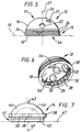
- the acetabular shell 12, illustrated in Figures 5 and 6, is a substantially hemispherical member having a generally convex outer bone-engaging surface 16. Opposite the outer surface 16 is a generally hemispherical, substantially concave liner surface 18.
- the shell may be characterized as having an equator region 15 and a polar region 17. Further, the shell includes an equatorial axis 19 and a polar axis 21.
- the outer surface 16, as shown in Figures 5 and 6, may include an apical hole 20 for seating a bone screw, and one or more additional holes 22 extending therethrough.
- the outer surface of the shell may further include surface features 24, such as ridges 26, to optimize fixation to bone and/or to encourage bone ingrowth.
- ridges 26 are the only surface features illustrated, one of ordinary skill in the art will readily appreciate that a variety of additional surface features can be formed on the outer surface to optimize performance of the prosthesis.
- the inner surface 18, as shown in Figures 1 through 4 and 6, includes a groove 28 that extends substantially parallel to the equatorial axis 19.
- the groove 28 may be continuous or it may be formed of discrete elements. Further, the groove 28 may extend partially or entirely around the circumference of the shell, either continuously or in discrete sections.
- the groove 28 is disposed in the equatorial region 15, and is spaced from the rim 32 of the shell, in the direction towards the polar region 17. Further, the embodiment of Figure 6 illustrates that the groove 28 is interrupted by recesses 30, which extend perpendicular to the equatorial axis 19.
- the groove 28 begins a distance of about 0.5 to 10 mm from the rim 32, in the direction towards the polar region 17.
- the dimensions of the groove will vary depending upon variables such as the dimensions of the shell, the dimensions of the liner and the dimensions of certain surface features present on the liner. In one embodiment, however, the groove 28 has a height 34 in the range of about 1 to 3 mm and a depth 36 of about 0.2 to 1.5 mm.
- the grooves may be separated from each other by about 0° to 180°, with 0° separation representing a continuous groove.
- the recesses 30 are intended to seat anti-rotation tabs 38 present on the liner 14, as discussed below, to prevent rotation of the liner 14 relative to the acetabular shell 12.
- the recesses 30 extend from the rim 32 towards the pole region 17.
- the height 40 of the recesses may be about 2 to 8 mm while the width 42 is about 1 to 3 mm.
- the depth 39 of the recesses may be in the range of about 0.5 to 4 mm.
- the shell 12 can be made from a variety of suitable materials. Generally, however, it is made from metals or metal alloys known to those having ordinary skill in the art.
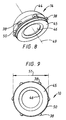
- the liner 14 has an equatorial region 41 and a rim 45. Opposite the equator region 41 is a polar region 43. An equatorial axis 47 of the liner extends parallel to the equatorial region 41 while a polar axis 45 extends perpendicular to the equatorial axis 47.
- the liner also has a convex outer surface 44, which is substantially hemispherically shaped and complementary to inner surface 18 of shell 12.
- the liner 14 also has a concave inner surface 46 which is intended to seat a femoral head of a hip prosthesis (not shown).
- the inner surface 46 should be a smooth, low friction surface.
- the tabs 38 can be of virtually any shape that is complementary to and matable within the recesses 30 of the shell 12. Accordingly, the tabs 38 protrude from the outer surface of the liner by about 0.5 to 4 mm and have a width in the range of about 1 to 3 mm.
- Tabs 38 may be positioned at virtually any location on the outer surface 44 of the liner 14. In one embodiment, the tabs 38 are positioned adjacent to the equatorial region 41, spaced approximately 0.5 to 1.0 from the rim 45 in the direction towards the polar region 43.
- the anti-rotation tabs 38 cooperate with the recesses 30 to prevent rotation of the liner 14 relative to the shell 12.
- No specific number of anti-rotation tabs 38 and recesses 30 is necessary to prevent rotation of the liner 14 relative to the shell 12 since any number will accomplish this objective.
- more than one anti-rotation tab 38 is present and from four to nine anti-rotation tabs can be used, depending upon the size of the liner and the shell.
- the outer surface 44 of the liner 14 also includes a raised ridge 50.
- the ridge cooperates with the groove 28 to selectively attach the liner to the shell.
- the ridge protrudes from the outer surface 44 of the liner 14 by a distance sufficient to prevent noninterfering insertion of the liner 14 within the shell 12. That is, the outer diameter 51 of the liner, measured at the ridge 50, is greater than the inner diameter 52 of the opening 54 of the shell.
- the ridge 50 should protrude from the outer surface 18 of the liner by a distance in the range of about 0.1 to 1.0 mm, and preferably about 0.1 to 0.6 mm. Similarly, the outer diameter 51 of the liner measured at the ridge 50 should exceed the inner diameter 52 of the opening 54 by about 0.1 to 1.5 mm.
- the ridge 50 may be a continuous structure, or it may be present on the outer surface of the liner in discrete sections. Further, the ridge 50 may extend partially or completely about the circumference of the liner, either continuously or in discrete sections.
- the ridge 50 may take on a variety of shapes. As shown in Figures 10A - 10C, the ridge is comprised of a superior wall 56, an inferior wall 58 and an end wall 62.
- the end wall 62 is generally parallel to the polar axis 49 of the liner as shown in Figure 10A, or it may conform in shape to the curvature of the outer surface 44 of the liner. Moreover, the end wall 62 may be spaced apart from the outer surface 44 of the liner by about 0.1 to 0.6 mm.
- the superior wall 56 may be parallel to the equatorial axis 47 of the liner ( Figure 10A), or it can be angled with respect to the equatorial axis 47 of the liner ( Figure 10B).
- the superior wall 56 forms a downwardly sloping, acute angle ( ⁇ ) with a line drawn parallel to the equatorial axis 47.
- the range of angle ( ⁇ ) may be about 0 to 45 degrees.
- the inferior wall 60 may extend parallel to the equatorial axis 47 ( Figure 10A), or it may be angled with respect to the equatorial axis ( Figure 10C).
- the ridge 50 may be present in numerous alternative geometries without departing from the scope of the invention.
- the invention provides a reliable and convenient attachment mechanism for selectively joining an acetabular shell to a liner component.
- the anti-rotation tabs 38 of the liner 14 are aligned with the recesses 30 of the shell 12. This orientation allows the outer surface of the liner to be inserted through opening 54 into the inner surface of the shell 12.
- a superior edge 56 of the ridge 50 will encounter the inferior wall 58 of rim 32, preventing further insertion of the liner within the shell.
- This resistance to further insertion can be overcome by applying additional force to the liner, enabling the force fitting of the ridge 50 within the opening 54.
- the force fitting can be accomplished by expansion of the opening, slight deformation of the ridge, or by contraction of the liner. Once the initial resistance to further insertion is overcome, further force will cause the ridge 50 to be seated within groove 28 enabling the liner to be mechanically engaged within the shell.
Landscapes
- Health & Medical Sciences (AREA)
- Orthopedic Medicine & Surgery (AREA)
- Cardiology (AREA)
- Oral & Maxillofacial Surgery (AREA)
- Transplantation (AREA)
- Engineering & Computer Science (AREA)
- Biomedical Technology (AREA)
- Heart & Thoracic Surgery (AREA)
- Vascular Medicine (AREA)
- Life Sciences & Earth Sciences (AREA)
- Animal Behavior & Ethology (AREA)
- General Health & Medical Sciences (AREA)
- Public Health (AREA)
- Veterinary Medicine (AREA)
- Prostheses (AREA)
Abstract

Description
- The invention relates to joint prostheses and more particularly to acetabular prostheses useful for partial or total replacement of the hip joint.
- Acetabular prostheses are known for use as a component for a total hip prosthesis. Acetabular prostheses typically include two separate components, one of which is a cup or shell that is affixed within a cavity reamed in healthy bone of the acetabulum. The acetabular cup may have an external (i.e., bone-contacting) geometry that is appropriate for a given patient. The inner geometry of the acetabular cup is usually characterized by a smooth, generally spherical cavity. The acetabular cup is typically made of a metal or metal alloy. In some cases, however, polymeric acetabular cups are utilized.
- A liner component is often mated with the inner geometry of the acetabular cup to provide a low friction bearing surface that articulates with a femoral head. The liner may have an outer, spherical surface that is of a size and shape to enable it to mate with the inner surface of the acetabular cup. The inner surface of the liner likewise is hemispherically shaped, having a smooth, low friction surface. As noted above, the femoral head seats within and articulates with the internal surface of the liner.
- Acetabular cups are often made from a metal or metal alloy. Some designs, however, utilize polymeric cups. One polymer commonly used to form the liner is ultrahigh molecular weight polyethylene. However, it is also possible to fabricate the liner from other materials, including metals, metal alloys and ceramics.
- Regardless of the materials and geometries used for the acetabular prosthesis, the acetabular cup and liner must be joined together, usually during the course of a surgical procedure. That is, a surgeon first implants the acetabular cup within the patient's acetabulum. Thereafter, the liner is separately affixed within the acetabular cup. A variety of liner designs exist and many are not symmetrical. Thus, the surgeon must determine the appropriate orientation of the liner with respect to the cup. Once the liner is properly oriented, it must remain so after affixation to the cup.
- Some acetabular prosthesis designs do not permit easy mating of the liner to the cup; the mating of some designs can, in fact, be quite challenging. Specialized tools or separate components may be necessary to join these components or to permanently affix them together. These additional steps may render the attachment process more time-consuming and may introduce the possibility that the liner and the shell will become misaligned due to surgical technique or for other reasons. Further, there is always a possibility that the joinder mechanism may fail to achieve its objective to secure the two components to one another.
- A number of patents describe acetabular prostheses designs that utilize a separate component to lock the liner and the shell together. Examples of such patents include U.S. Patent Nos. 4,619,658; 4,770,658; 4,784,663; 4,969,910; 5,049,158; 5,171,285; 5,263,988; 5,425,779; 5,507,826; and 5,658,348.
- Other known designs do not require a separate locking mechanism to join the liner and the cup. Instead, an interference fit or another form of mechanical engagement of the two components is relied upon. Examples of patents disclosing such attachment mechanisms include U.S. Patent Nos. 4,172,296; 4,650,491; 5,376,122; 5,443,519; and 5,549,698.
- Despite the acetabular prostheses designs that are known to exist, there is still a need for an acetabular prosthesis design that provides excellent attachment strength between the liner and the cup while at the same time providing ease of assembly without the need for additional assembly tools or components.
- An acetabular prosthesis has a shell component that is implantable within bone and a liner component that is matable to the shell. The shell has a generally convex bone engaging outer surface and a generally concave inner surface. A groove is formed in the inner surface of the shell and extends about at least a portion of the inner circumference of the shell. The liner, which has a polar region and an equator region, has an inner concave surface and an outer, convex surface with a shape complementary to and matable within the inner surface of the shell. One or more positive surface features is formed on the outer surface of the liner, adapted for selective mating with the groove of the shell. The liner may be joined to the shell by press fitting the two components together such that the positive surface features engage the groove.
- The prosthesis may also have a structure to prevent rotation of the liner with respect to the shell after joinder of the two components. The anti-rotation mechanism may be in the form of one or more tabs in the outer surface of the liner, adjacent to the positive surface features. At least one recess is formed in the shell with a size and shape complementary to the tabs such that each tab is matable within one of the recesses.
- One advantage of the prosthesis of the present invention lies in its ease of assembly and its ability to provide good attachment strength between the liner and the shell.
-
- Figure 1 is a bottom, perspective view of an acetabular prosthesis according to the present invention.
- Figure 2 is a bottom view of the acetabular prosthesis shown in Figure 1.
- Figure 3 is an elevated sectional view of the prosthesis shown in Figure 2, at lines 3-3.
- Figure 4 is a detailed view of portion A of the prosthesis shown in Figure 3.
- Figure 5 is an elevated view of a shell component useful with the acetabular prosthesis of the invention.
- Figure 6 is a perspective view of the shell component of Figure 5.
- Figure 7 is an elevated view of a liner component useful with the acetabular prosthesis of the invention.
- Figure 8 is a perspective view of another liner component useful with the acetabular prosthesis of the present invention.
- Figure 9 is a bottom view of the liner component shown in Figure 8.
- Figure 10A is a detailed sectional view of a portion of a liner constructed according to one embodiment of the present invention.
- Figure 10B is a detailed sectional view of a portion of a liner constructed according to another embodiment of the present invention.
- Figure 10C is a detailed sectional view of a portion of a liner constructed according to another embodiment of the invention.
-
- The present invention provides an acetabular prosthesis with an effective and convenient mechanism for joining and securing the acetabular shell and liner components to each other. Referring to Figures 1 through 4, the
acetabular prosthesis 10 includes anacetabular shell 12 and aliner 14 which are selectively attachable to one another through an interlocking engagement. - The
acetabular shell 12, illustrated in Figures 5 and 6, is a substantially hemispherical member having a generally convex outer bone-engaging surface 16. Opposite theouter surface 16 is a generally hemispherical, substantiallyconcave liner surface 18. The shell may be characterized as having anequator region 15 and apolar region 17. Further, the shell includes anequatorial axis 19 and a polar axis 21. - The
outer surface 16, as shown in Figures 5 and 6, may include anapical hole 20 for seating a bone screw, and one or moreadditional holes 22 extending therethrough. The outer surface of the shell may further include surface features 24, such asridges 26, to optimize fixation to bone and/or to encourage bone ingrowth. Althoughridges 26 are the only surface features illustrated, one of ordinary skill in the art will readily appreciate that a variety of additional surface features can be formed on the outer surface to optimize performance of the prosthesis. - The
inner surface 18, as shown in Figures 1 through 4 and 6, includes agroove 28 that extends substantially parallel to theequatorial axis 19. Thegroove 28 may be continuous or it may be formed of discrete elements. Further, thegroove 28 may extend partially or entirely around the circumference of the shell, either continuously or in discrete sections. In the embodiment illustrated in Figures 3 and 6, thegroove 28 is disposed in theequatorial region 15, and is spaced from therim 32 of the shell, in the direction towards thepolar region 17. Further, the embodiment of Figure 6 illustrates that thegroove 28 is interrupted byrecesses 30, which extend perpendicular to theequatorial axis 19. - In one embodiment, the
groove 28 begins a distance of about 0.5 to 10 mm from therim 32, in the direction towards thepolar region 17. The dimensions of the groove will vary depending upon variables such as the dimensions of the shell, the dimensions of the liner and the dimensions of certain surface features present on the liner. In one embodiment, however, thegroove 28 has aheight 34 in the range of about 1 to 3 mm and adepth 36 of about 0.2 to 1.5 mm. - The grooves may be separated from each other by about 0° to 180°, with 0° separation representing a continuous groove.
- The
recesses 30 are intended to seatanti-rotation tabs 38 present on theliner 14, as discussed below, to prevent rotation of theliner 14 relative to theacetabular shell 12. Therecesses 30 extend from therim 32 towards thepole region 17. Theheight 40 of the recesses may be about 2 to 8 mm while thewidth 42 is about 1 to 3 mm. Thedepth 39 of the recesses may be in the range of about 0.5 to 4 mm. - The
shell 12 can be made from a variety of suitable materials. Generally, however, it is made from metals or metal alloys known to those having ordinary skill in the art. - The
liner 14 has anequatorial region 41 and arim 45. Opposite theequator region 41 is apolar region 43. Anequatorial axis 47 of the liner extends parallel to theequatorial region 41 while apolar axis 45 extends perpendicular to theequatorial axis 47. The liner also has a convexouter surface 44, which is substantially hemispherically shaped and complementary toinner surface 18 ofshell 12. Theliner 14 also has a concaveinner surface 46 which is intended to seat a femoral head of a hip prosthesis (not shown). One of ordinary skill in the art will appreciate that theinner surface 46 should be a smooth, low friction surface. - The
liner 14, as illustrated in Figures 3, 4 and 7-9, includes one or moreanti-rotation tabs 38 which protrude from theouter surface 14. Thetabs 38 can be of virtually any shape that is complementary to and matable within therecesses 30 of theshell 12. Accordingly, thetabs 38 protrude from the outer surface of the liner by about 0.5 to 4 mm and have a width in the range of about 1 to 3 mm. -
Tabs 38 may be positioned at virtually any location on theouter surface 44 of theliner 14. In one embodiment, thetabs 38 are positioned adjacent to theequatorial region 41, spaced approximately 0.5 to 1.0 from therim 45 in the direction towards thepolar region 43. - As noted above, the
anti-rotation tabs 38 cooperate with therecesses 30 to prevent rotation of theliner 14 relative to theshell 12. No specific number ofanti-rotation tabs 38 and recesses 30 is necessary to prevent rotation of theliner 14 relative to theshell 12 since any number will accomplish this objective. Generally, however, more than oneanti-rotation tab 38 is present and from four to nine anti-rotation tabs can be used, depending upon the size of the liner and the shell. - The
outer surface 44 of theliner 14 also includes a raisedridge 50. The ridge cooperates with thegroove 28 to selectively attach the liner to the shell. The ridge protrudes from theouter surface 44 of theliner 14 by a distance sufficient to prevent noninterfering insertion of theliner 14 within theshell 12. That is, the outer diameter 51 of the liner, measured at theridge 50, is greater than theinner diameter 52 of theopening 54 of the shell. Theridge 50 should protrude from theouter surface 18 of the liner by a distance in the range of about 0.1 to 1.0 mm, and preferably about 0.1 to 0.6 mm. Similarly, the outer diameter 51 of the liner measured at theridge 50 should exceed theinner diameter 52 of theopening 54 by about 0.1 to 1.5 mm. - The
ridge 50 may be a continuous structure, or it may be present on the outer surface of the liner in discrete sections. Further, theridge 50 may extend partially or completely about the circumference of the liner, either continuously or in discrete sections. - The
ridge 50 may take on a variety of shapes. As shown in Figures 10A - 10C, the ridge is comprised of asuperior wall 56, aninferior wall 58 and anend wall 62. Theend wall 62 is generally parallel to thepolar axis 49 of the liner as shown in Figure 10A, or it may conform in shape to the curvature of theouter surface 44 of the liner. Moreover, theend wall 62 may be spaced apart from theouter surface 44 of the liner by about 0.1 to 0.6 mm. Thesuperior wall 56 may be parallel to theequatorial axis 47 of the liner (Figure 10A), or it can be angled with respect to theequatorial axis 47 of the liner (Figure 10B). In one embodiment, thesuperior wall 56 forms a downwardly sloping, acute angle (α) with a line drawn parallel to theequatorial axis 47. The range of angle (α) may be about 0 to 45 degrees. Similarly, the inferior wall 60 may extend parallel to the equatorial axis 47 (Figure 10A), or it may be angled with respect to the equatorial axis (Figure 10C). One of ordinary skill in the art will readily appreciate that theridge 50 may be present in numerous alternative geometries without departing from the scope of the invention. - As noted above, the invention provides a reliable and convenient attachment mechanism for selectively joining an acetabular shell to a liner component. To attach these two components together, the
anti-rotation tabs 38 of theliner 14 are aligned with therecesses 30 of theshell 12. This orientation allows the outer surface of the liner to be inserted through opening 54 into the inner surface of theshell 12. During the insertion process asuperior edge 56 of theridge 50 will encounter theinferior wall 58 ofrim 32, preventing further insertion of the liner within the shell. This resistance to further insertion can be overcome by applying additional force to the liner, enabling the force fitting of theridge 50 within theopening 54. The force fitting can be accomplished by expansion of the opening, slight deformation of the ridge, or by contraction of the liner. Once the initial resistance to further insertion is overcome, further force will cause theridge 50 to be seated withingroove 28 enabling the liner to be mechanically engaged within the shell. - It is understood that various modifications may be made to the invention described herein without departing from the intended scope thereof. Further, all dimensions are intended to serve only as examples; one of ordinary skill in the art may easily determine additional or alternative dimensions. All references cited herein are expressly incorporated by reference in their entirety.
Claims (22)
- An acetabular cup prosthesis, comprising:a shell component having a generally convex bone-engaging outer surface and a generally concave inner surface with a groove formed in the inner surface thereof and extending about at least a portion of the circumference of the inner surface of the shell component;a liner component having an inner, concave surface and an outer, convex surface with a shape complementary to and matable within the inner surface of the shell component, the liner component having a polar region and an equator region; andat least one positive surface feature formed on the outer surface of the liner component, the at least one positive surface feature being selectively matable with the groove of the shell and having (i) an end wall spaced apart from the outer, convex surface and (ii) opposed side walls connecting the end wall to the outer, convex surface of the shell component.
- The prosthesis of claim 1, wherein the groove extends about the entire circumference of the inner surface of the shell component.
- The prosthesis of claim 1, wherein the at least one positive surface feature is adjacent the equator region of the liner component.
- The prosthesis of claim 1 wherein the at least one positive surface feature comprises a plurality of discrete positive surface features that are formed on outer convex surface of the liner component.
- The prosthesis of claim 2 wherein the at least one positive surface feature comprises a single positive surface feature extending continuously about the entire circumference of the liner component.
- The prosthesis of claim 1 wherein the end wall extends substantially parallel to the outer, convex surface of the shell component.
- The prosthesis of claim 1 wherein the opposed side walls extend substantially normal to the end wall.
- The prosthesis of claim 1 wherein the opposed side walls comprise a superior side wall and an inferior side wall, the superior side wall forming a downwardly sloping acute angle with an equatorial a line drawn parallel to an equatorial axis of the liner.
- The prosthesis of claim 8 wherein the angle is in the range of 0 to 45 degrees.
- The prosthesis of claim 1, further comprising:at least one anti-rotation tab member formed on the outer surface of the liner component, adjacent to the at least one positive surface feature; andat least one recess formed in the inner surface of the shell component, the at least one recess having a size and shape complementary to the at least one anti-rotation tab member such that each of the at least one recesses is effective to matingly engage one of the at least one anti-rotation tab members.
- The prosthesis of claim 10 wherein at least a portion of each of the at least one anti-rotation tab members and the at least one recess is substantially hemispherically shaped.
- The prosthesis of claim 1 wherein the groove has a height in the range of about 1 to 3 mm.
- The prosthesis of claim 12 wherein the groove has a depth in the range of about 0.2 to 1.5 mm.
- The prosthesis of claim 12 wherein the end wall of the at least one positive surface feature is spaced apart from the outer surface of the liner by a distance in the range of about 0.1 to 0.6 mm.
- The prosthesis of claim 14 wherein each of the at least one positive surface features has a height in the range of about 1 to 3 mm.
- The prosthesis of claim 1, wherein the liner component and shell component are matable to one another by forcing the liner component within the shell component to enable the at least one positive surface feature to be engaged within the groove.
- The prosthesis of claim 1 wherein a diameter of the liner component measured from the end wall of the at least one positive surface feature is greater than an inner diameter of the shell component measured at an equator of the shell component.
- An acetabular cup prosthesis, comprising:a shell component having a generally convex bone-engaging outer surface and a generally concave inner surface with a groove formed in the inner surface thereof and extending about of the circumference of the inner surface of the shell component;a liner component having an inner concave surface and an outer, convex surface with a shape complementary to and matable within the inner surface of the shell component, the liner component having a polar region and an equator region; anda continuous positive surface feature formed on and extending about the circumference of the outer surface of the liner component, the continuous positive surface feature being selectively matable with the groove of the shell.
- The prosthesis of claim 18, further comprising:at least one anti-rotation tab member formed on the outer surface of the liner component, adjacent to the continuous positive surface feature; andat least one recess formed in the inner surface of the shell component, the at least one recess having a size and shape complementary to the at least one anti-rotation tab member such that each of the at least one recesses is effective to matingly engage one of the at least one anti-rotation tab members.
- The prosthesis of claim 18 wherein the groove has a depth in the range of about 0.2 to 1.5 mm.
- The prosthesis of claim 20 wherein the groove has a height in the range of about 1 to 3 mm.
- The prosthesis of claim 20 wherein an end wall of the continuous positive surface feature is spaced apart from the outer surface of the liner by a distance in the range of about 0.1 to 0.6 mm.
Applications Claiming Priority (2)
| Application Number | Priority Date | Filing Date | Title |
|---|---|---|---|
| US998881 | 1997-12-29 | ||
| US08/998,881 US6152961A (en) | 1997-12-29 | 1997-12-29 | Acetabular prosthesis assembly |
Publications (3)
| Publication Number | Publication Date |
|---|---|
| EP0927547A2 true EP0927547A2 (en) | 1999-07-07 |
| EP0927547A3 EP0927547A3 (en) | 1999-12-01 |
| EP0927547B1 EP0927547B1 (en) | 2003-12-17 |
Family
ID=25545641
Family Applications (1)
| Application Number | Title | Priority Date | Filing Date |
|---|---|---|---|
| EP98310726A Expired - Lifetime EP0927547B1 (en) | 1997-12-29 | 1998-12-24 | Acetabular prosthesis assembly |
Country Status (5)
| Country | Link |
|---|---|
| US (1) | US6152961A (en) |
| EP (1) | EP0927547B1 (en) |
| JP (1) | JP4104758B2 (en) |
| BR (1) | BR9805808A (en) |
| DE (1) | DE69820581T2 (en) |
Cited By (6)
| Publication number | Priority date | Publication date | Assignee | Title |
|---|---|---|---|---|
| EP1066806A1 (en) * | 1999-07-08 | 2001-01-10 | Biomet Merck Deutschland GmbH | Cup for a hip joint endoprosthesis |
| WO2003020180A1 (en) | 2001-08-20 | 2003-03-13 | Biomet Merck Gmbh | Artificial hip joint acetabulum |
| ES2207385A1 (en) * | 2002-02-13 | 2004-05-16 | German Perez Cosias | Hemispherical profiled cemented apothecary's measure includes titanium coated with plasma and hydroxy apatite in a specific configuration |
| US8123815B2 (en) | 2008-11-24 | 2012-02-28 | Biomet Manufacturing Corp. | Multiple bearing acetabular prosthesis |
| US8308810B2 (en) | 2009-07-14 | 2012-11-13 | Biomet Manufacturing Corp. | Multiple bearing acetabular prosthesis |
| US8679187B2 (en) | 2006-03-20 | 2014-03-25 | Smith & Nephew, Inc. | Acetabular cup assembly for multiple bearing materials |
Families Citing this family (38)
| Publication number | Priority date | Publication date | Assignee | Title |
|---|---|---|---|---|
| ES2286131T3 (en) * | 2000-07-31 | 2007-12-01 | Massachusetts General Hospital | CONSTREATED MONOPOLAR ACETABULAR COMPONENT. |
| US7326253B2 (en) * | 2001-11-16 | 2008-02-05 | Depuy Products, Inc. | Prosthetic cup assembly having increased assembly congruency |
| EP1539050B1 (en) * | 2002-09-19 | 2007-08-01 | Malan De Villiers | Arthroplasty implant |
| US6926740B2 (en) | 2002-12-13 | 2005-08-09 | Depuy Products, Inc. | Modular orthopaedic implant apparatus and method |
| FR2849769B1 (en) * | 2003-01-13 | 2005-10-14 | Biotechni | IMPLANT AND ARTICULAR PROSTHESIS COMPRISING SAME |
| US7344565B2 (en) * | 2003-02-04 | 2008-03-18 | Wright Medical Technology, Inc. | Acetabular component insertion and extraction tool for use therewith, and method of locking an acetabular component to an insertion and extraction tool |
| CN100418493C (en) * | 2003-03-13 | 2008-09-17 | 钱本文 | Natural innominatum devices |
| US7108720B2 (en) * | 2003-03-31 | 2006-09-19 | Depuy Products, Inc. | Reduced wear orthopaedic implant apparatus and method |
| US7125037B2 (en) * | 2003-10-21 | 2006-10-24 | Autoliv Asp, Inc. | Inflatable cushion retention system |
| US7169185B2 (en) * | 2004-05-26 | 2007-01-30 | Impact Science And Technology, Inc. | Canine acetabular cup |
| US20060206211A1 (en) * | 2005-02-22 | 2006-09-14 | Ortho Development Corporation | Bipolar hip prosthesis with free floating ring |
| US20070219640A1 (en) * | 2006-03-16 | 2007-09-20 | Active Implants Corporation | Ceramic-on-ceramic prosthetic device coupled to a flexible bone interface |
| DE102007031667A1 (en) * | 2006-08-04 | 2008-02-14 | Ceramtec Ag Innovative Ceramic Engineering | Insertion of vibration-damping elements in prosthetic systems for manipulation and damping of natural frequencies |
| US20080053169A1 (en) * | 2006-08-30 | 2008-03-06 | Victoria Marie Ricker | Theft deterrent device for bags |
| US8512413B2 (en) | 2006-11-07 | 2013-08-20 | Biomedflex, Llc | Prosthetic knee joint |
| US8308812B2 (en) | 2006-11-07 | 2012-11-13 | Biomedflex, Llc | Prosthetic joint assembly and joint member therefor |
| US9005307B2 (en) | 2006-11-07 | 2015-04-14 | Biomedflex, Llc | Prosthetic ball-and-socket joint |
| US20110166671A1 (en) | 2006-11-07 | 2011-07-07 | Kellar Franz W | Prosthetic joint |
| US7766971B2 (en) * | 2006-12-12 | 2010-08-03 | Exactech, Inc. | Constrained liner locking ring and polyethylene liner congruency feature |
| US8163028B2 (en) | 2007-01-10 | 2012-04-24 | Biomet Manufacturing Corp. | Knee joint prosthesis system and method for implantation |
| US8328873B2 (en) | 2007-01-10 | 2012-12-11 | Biomet Manufacturing Corp. | Knee joint prosthesis system and method for implantation |
| JP5448842B2 (en) | 2007-01-10 | 2014-03-19 | バイオメト マニファクチャリング コーポレイション | Knee joint prosthesis system and implantation method |
| US8187280B2 (en) | 2007-10-10 | 2012-05-29 | Biomet Manufacturing Corp. | Knee joint prosthesis system and method for implantation |
| US8562616B2 (en) | 2007-10-10 | 2013-10-22 | Biomet Manufacturing, Llc | Knee joint prosthesis system and method for implantation |
| US8052755B2 (en) * | 2008-05-09 | 2011-11-08 | Remi Sciences, Inc. | Ulnar head prosthesis system |
| EP2174621B1 (en) * | 2008-10-07 | 2013-07-17 | Finsbury (Development) Limited | Prosthesis |
| CA2760788A1 (en) * | 2009-05-07 | 2010-11-11 | Smith & Nephew, Inc. | Modular trial heads for a prosthetic |
| JP5951607B2 (en) * | 2010-07-29 | 2016-07-13 | メイヨ ファンデーション フォア メディカル エディケイション アンド リサーチ | Acetabular cup prosthesis |
| US8585769B2 (en) | 2011-01-14 | 2013-11-19 | Zimmer, Inc. | Acetabular liner system |
| US8398718B2 (en) | 2011-02-16 | 2013-03-19 | Rodney Ian Walter Richardson | Acetabular cup with rotatable bearing member |
| US8465549B2 (en) | 2011-02-16 | 2013-06-18 | Rodney Ian Walter Richardson | Acetabular cup with rotatable bearing |
| US9023112B2 (en) | 2011-02-24 | 2015-05-05 | Depuy (Ireland) | Maintaining proper mechanics THA |
| US9668745B2 (en) | 2011-12-19 | 2017-06-06 | Depuy Ireland Unlimited Company | Anatomical concentric spheres THA |
| US9204978B2 (en) | 2012-05-29 | 2015-12-08 | Zimmer, Inc. | Modular screw apparatus and method |
| US8858645B2 (en) | 2012-06-21 | 2014-10-14 | DePuy Synthes Products, LLC | Constrained mobile bearing hip assembly |
| EP3332739B1 (en) | 2014-11-07 | 2019-04-24 | SMed - TA/TD LLC | Implants with groove patterns and soft tissue attachment features |
| US11103367B2 (en) | 2019-02-15 | 2021-08-31 | Encore Medical, L.P. | Acetabular liner |
| WO2021158661A1 (en) | 2020-02-04 | 2021-08-12 | Encore Medical, Lp Dba Djo Surgical | Acetabular cup system |
Citations (6)
| Publication number | Priority date | Publication date | Assignee | Title |
|---|---|---|---|---|
| US4619658A (en) | 1982-02-24 | 1986-10-28 | Pappas Michael J | Spherical kinematic joint |
| US4770658A (en) | 1987-05-01 | 1988-09-13 | Zimmer, Inc. | Joint prosthesis |
| US4784663A (en) | 1986-02-19 | 1988-11-15 | Pfizer Hospital Products Group, Inc. | Acetabular cup assembly |
| US4969910A (en) | 1987-11-11 | 1990-11-13 | Sulzer Brothers Limited | Acetabular cup prosthesis |
| US5049158A (en) | 1990-04-20 | 1991-09-17 | Boehringer Mannheim Corporation | Acetabular cup assembly |
| US5171285A (en) | 1992-02-18 | 1992-12-15 | Zimmer, Inc. | Acetabular cup with shiftable elevated rim liner |
Family Cites Families (29)
| Publication number | Priority date | Publication date | Assignee | Title |
|---|---|---|---|---|
| US3903549A (en) * | 1974-06-12 | 1975-09-09 | William Minor Deyerle | Acetabular cup prosthesis component for total or subtotal hip prosthesis system |
| US4172296A (en) * | 1978-02-01 | 1979-10-30 | Howmedica, Inc. | Bicentric joint prosthesis |
| US4678472A (en) * | 1983-03-08 | 1987-07-07 | Joint Medical Products Corporation | Ball and socket bearing for artificial joint |
| CA1240101A (en) * | 1983-05-06 | 1988-08-09 | Michael J. Pappas | Multi-component prosthesis with increased wall flexibility facilitating component assembly |
| US4704127A (en) * | 1986-01-23 | 1987-11-03 | Osteonics Corp. | Dual-geometry acetabular cup component and method of implant |
| US4650491A (en) * | 1986-02-14 | 1987-03-17 | Pfizer Hospital Products Group, Inc. | Locking mechanism for prosthesis components |
| FR2595562B1 (en) * | 1986-03-13 | 1992-08-28 | Rhenter Jean Luc | PROSTHESIS CUP |
| US4795469A (en) * | 1986-07-23 | 1989-01-03 | Indong Oh | Threaded acetabular cup and method |
| CH673087A5 (en) * | 1987-10-28 | 1990-02-15 | Sulzer Ag | |
| US5217499A (en) * | 1988-08-17 | 1993-06-08 | Minnesota Mining And Manufacturing Company | Rim-bearing acetabular component of hip joint prosthesis |
| FR2648703B1 (en) * | 1989-06-21 | 1998-04-03 | Benoist Girard Cie | COTYL FOR HIP PROSTHESIS |
| GB9000124D0 (en) * | 1990-01-04 | 1990-03-07 | Howmedica | Prosthetic bearing assembly |
| US5314487A (en) * | 1991-02-14 | 1994-05-24 | Smith & Nephew Richards Inc. | Acetabular prosthesis with anchoring pegs |
| US5226917A (en) * | 1991-02-14 | 1993-07-13 | Smith & Nephew Richards Inc. | Acetabular prosthesis with anchoring pegs |
| KR100236324B1 (en) * | 1991-08-20 | 2000-03-02 | 게리 제이. 밀러 | Bipolar endoprosthesis |
| DE4211346C2 (en) * | 1992-04-04 | 1995-08-10 | S & G Implants Gmbh | Cup of a hip joint endoprosthesis |
| JPH05344991A (en) * | 1992-06-15 | 1993-12-27 | Yanmar Diesel Engine Co Ltd | Joint prosthesis device |
| US5425779A (en) * | 1992-08-05 | 1995-06-20 | U.S. Medical Products, Inc. | Prosthetic implant for joint structures |
| DE9212419U1 (en) * | 1992-09-15 | 1994-01-27 | Link Waldemar Gmbh Co | Joint socket for a hip joint endoprosthesis |
| US5551871A (en) * | 1993-03-05 | 1996-09-03 | Besselink; Petrus A. | Temperature-sensitive medical/dental apparatus |
| US5443519A (en) * | 1993-04-22 | 1995-08-22 | Implex Corporation | Prosthetic ellipsoidal acetabular cup |
| DE59308586D1 (en) * | 1993-08-30 | 1998-06-25 | Sulzer Orthopaedie Ag | Artificial acetabular cup |
| US5480448A (en) * | 1993-09-20 | 1996-01-02 | Mikhail; W. E. Michael | Acetabular cup groove insert |
| US5549691A (en) * | 1994-02-03 | 1996-08-27 | Harwin; Steven F. | Acetabular cup |
| ATE193821T1 (en) * | 1994-12-13 | 2000-06-15 | Piero Garosi | ANCHORING SHELL OF A HIP JOINT POCKET |
| US5658348A (en) * | 1996-09-09 | 1997-08-19 | Bristol-Myers Squibb Company | Acetabular implant with threaded liner and locking ring |
| AU729561B2 (en) * | 1996-10-23 | 2001-02-01 | Smith & Nephew, Inc. | Acetabular cup body prosthesis |
| US5938702A (en) * | 1997-10-31 | 1999-08-17 | Sulzer Orthopedics Inc. | Locking mechanism for acetabular cup |
| US5935175A (en) * | 1998-03-13 | 1999-08-10 | Johnson & Johnson Professional, Inc. | Acetabular prosthesis with ring lock mechanism |
-
1997
- 1997-12-29 US US08/998,881 patent/US6152961A/en not_active Expired - Lifetime
-
1998
- 1998-12-24 DE DE69820581T patent/DE69820581T2/en not_active Expired - Lifetime
- 1998-12-24 EP EP98310726A patent/EP0927547B1/en not_active Expired - Lifetime
- 1998-12-28 JP JP37738798A patent/JP4104758B2/en not_active Expired - Lifetime
- 1998-12-29 BR BR9805808-8A patent/BR9805808A/en not_active Application Discontinuation
Patent Citations (6)
| Publication number | Priority date | Publication date | Assignee | Title |
|---|---|---|---|---|
| US4619658A (en) | 1982-02-24 | 1986-10-28 | Pappas Michael J | Spherical kinematic joint |
| US4784663A (en) | 1986-02-19 | 1988-11-15 | Pfizer Hospital Products Group, Inc. | Acetabular cup assembly |
| US4770658A (en) | 1987-05-01 | 1988-09-13 | Zimmer, Inc. | Joint prosthesis |
| US4969910A (en) | 1987-11-11 | 1990-11-13 | Sulzer Brothers Limited | Acetabular cup prosthesis |
| US5049158A (en) | 1990-04-20 | 1991-09-17 | Boehringer Mannheim Corporation | Acetabular cup assembly |
| US5171285A (en) | 1992-02-18 | 1992-12-15 | Zimmer, Inc. | Acetabular cup with shiftable elevated rim liner |
Cited By (8)
| Publication number | Priority date | Publication date | Assignee | Title |
|---|---|---|---|---|
| EP1066806A1 (en) * | 1999-07-08 | 2001-01-10 | Biomet Merck Deutschland GmbH | Cup for a hip joint endoprosthesis |
| WO2003020180A1 (en) | 2001-08-20 | 2003-03-13 | Biomet Merck Gmbh | Artificial hip joint acetabulum |
| ES2207385A1 (en) * | 2002-02-13 | 2004-05-16 | German Perez Cosias | Hemispherical profiled cemented apothecary's measure includes titanium coated with plasma and hydroxy apatite in a specific configuration |
| US8679187B2 (en) | 2006-03-20 | 2014-03-25 | Smith & Nephew, Inc. | Acetabular cup assembly for multiple bearing materials |
| US8123815B2 (en) | 2008-11-24 | 2012-02-28 | Biomet Manufacturing Corp. | Multiple bearing acetabular prosthesis |
| US9445903B2 (en) | 2008-11-24 | 2016-09-20 | Biomet Manufacturing, Llc | Multi-bearing acetabular prosthesis |
| US8308810B2 (en) | 2009-07-14 | 2012-11-13 | Biomet Manufacturing Corp. | Multiple bearing acetabular prosthesis |
| US9445904B2 (en) | 2009-07-14 | 2016-09-20 | Biomet Manufacturing, Llc | Multiple bearing acetabular prosthesis |
Also Published As
| Publication number | Publication date |
|---|---|
| JPH11253470A (en) | 1999-09-21 |
| EP0927547B1 (en) | 2003-12-17 |
| JP4104758B2 (en) | 2008-06-18 |
| DE69820581T2 (en) | 2004-09-16 |
| DE69820581D1 (en) | 2004-01-29 |
| US6152961A (en) | 2000-11-28 |
| BR9805808A (en) | 1999-12-07 |
| EP0927547A3 (en) | 1999-12-01 |
Similar Documents
| Publication | Publication Date | Title |
|---|---|---|
| US6152961A (en) | Acetabular prosthesis assembly | |
| US6162256A (en) | Acetabular prosthesis | |
| US5935175A (en) | Acetabular prosthesis with ring lock mechanism | |
| EP1133958B1 (en) | Prosthetic cup assembly which includes components possessing self-locking taper | |
| EP1506749B1 (en) | Constrained acetabular liner | |
| EP1493406B1 (en) | Acetabular component | |
| US5263988A (en) | Bipolar endoprosthesis | |
| US4650491A (en) | Locking mechanism for prosthesis components | |
| US7326253B2 (en) | Prosthetic cup assembly having increased assembly congruency | |
| US5782929A (en) | Acetabular shell having sintered screw hole plugs | |
| US5108445A (en) | Prosthetic bearing assembly | |
| US20070203583A1 (en) | Method and apparatus for aligning a taper lock connection | |
| US10307255B1 (en) | Acetabular cup assembly | |
| WO1995022944A1 (en) | Acetabular cup composite insert and assembly method | |
| US6379389B1 (en) | Artificial hip joint socket | |
| EP1308141A1 (en) | An acetabular cup for a hip joint prosthesis | |
| WO2009147395A2 (en) | Acetabular cup |
Legal Events
| Date | Code | Title | Description |
|---|---|---|---|
| PUAI | Public reference made under article 153(3) epc to a published international application that has entered the european phase |
Free format text: ORIGINAL CODE: 0009012 |
|
| AK | Designated contracting states |
Kind code of ref document: A2 Designated state(s): DE ES FR GB IT SE |
|
| AX | Request for extension of the european patent |
Free format text: AL;LT;LV;MK;RO;SI |
|
| PUAL | Search report despatched |
Free format text: ORIGINAL CODE: 0009013 |
|
| AK | Designated contracting states |
Kind code of ref document: A3 Designated state(s): AT BE CH CY DE DK ES FI FR GB GR IE IT LI LU MC NL PT SE |
|
| AX | Request for extension of the european patent |
Free format text: AL;LT;LV;MK;RO;SI |
|
| 17P | Request for examination filed |
Effective date: 20000126 |
|
| AKX | Designation fees paid |
Free format text: DE ES FR GB IT SE |
|
| 17Q | First examination report despatched |
Effective date: 20020220 |
|
| RAP1 | Party data changed (applicant data changed or rights of an application transferred) |
Owner name: DEPUY PRODUCTS, INC. |
|
| RAP1 | Party data changed (applicant data changed or rights of an application transferred) |
Owner name: DEPUY PRODUCTS, INC. |
|
| GRAH | Despatch of communication of intention to grant a patent |
Free format text: ORIGINAL CODE: EPIDOS IGRA |
|
| GRAS | Grant fee paid |
Free format text: ORIGINAL CODE: EPIDOSNIGR3 |
|
| GRAA | (expected) grant |
Free format text: ORIGINAL CODE: 0009210 |
|
| AK | Designated contracting states |
Kind code of ref document: B1 Designated state(s): DE ES FR GB IT SE |
|
| REG | Reference to a national code |
Ref country code: GB Ref legal event code: FG4D |
|
| REF | Corresponds to: |
Ref document number: 69820581 Country of ref document: DE Date of ref document: 20040129 Kind code of ref document: P |
|
| PG25 | Lapsed in a contracting state [announced via postgrant information from national office to epo] |
Ref country code: SE Free format text: LAPSE BECAUSE OF FAILURE TO SUBMIT A TRANSLATION OF THE DESCRIPTION OR TO PAY THE FEE WITHIN THE PRESCRIBED TIME-LIMIT Effective date: 20040317 |
|
| PG25 | Lapsed in a contracting state [announced via postgrant information from national office to epo] |
Ref country code: ES Free format text: LAPSE BECAUSE OF FAILURE TO SUBMIT A TRANSLATION OF THE DESCRIPTION OR TO PAY THE FEE WITHIN THE PRESCRIBED TIME-LIMIT Effective date: 20040328 |
|
| ET | Fr: translation filed | ||
| PLBE | No opposition filed within time limit |
Free format text: ORIGINAL CODE: 0009261 |
|
| STAA | Information on the status of an ep patent application or granted ep patent |
Free format text: STATUS: NO OPPOSITION FILED WITHIN TIME LIMIT |
|
| 26N | No opposition filed |
Effective date: 20040920 |
|
| REG | Reference to a national code |
Ref country code: FR Ref legal event code: PLFP Year of fee payment: 19 |
|
| REG | Reference to a national code |
Ref country code: FR Ref legal event code: PLFP Year of fee payment: 20 |
|
| PGFP | Annual fee paid to national office [announced via postgrant information from national office to epo] |
Ref country code: FR Payment date: 20171113 Year of fee payment: 20 |
|
| PGFP | Annual fee paid to national office [announced via postgrant information from national office to epo] |
Ref country code: GB Payment date: 20171220 Year of fee payment: 20 |
|
| PGFP | Annual fee paid to national office [announced via postgrant information from national office to epo] |
Ref country code: DE Payment date: 20171220 Year of fee payment: 20 |
|
| PGFP | Annual fee paid to national office [announced via postgrant information from national office to epo] |
Ref country code: IT Payment date: 20171221 Year of fee payment: 20 |
|
| REG | Reference to a national code |
Ref country code: DE Ref legal event code: R071 Ref document number: 69820581 Country of ref document: DE |
|
| REG | Reference to a national code |
Ref country code: GB Ref legal event code: PE20 Expiry date: 20181223 |
|
| PG25 | Lapsed in a contracting state [announced via postgrant information from national office to epo] |
Ref country code: GB Free format text: LAPSE BECAUSE OF EXPIRATION OF PROTECTION Effective date: 20181223 |