EP0928606A1 - An intravascular stent having curved bridges for connecting adjacent hoops - Google Patents
An intravascular stent having curved bridges for connecting adjacent hoops Download PDFInfo
- Publication number
- EP0928606A1 EP0928606A1 EP99300135A EP99300135A EP0928606A1 EP 0928606 A1 EP0928606 A1 EP 0928606A1 EP 99300135 A EP99300135 A EP 99300135A EP 99300135 A EP99300135 A EP 99300135A EP 0928606 A1 EP0928606 A1 EP 0928606A1
- Authority
- EP
- European Patent Office
- Prior art keywords
- stent
- bridges
- struts
- loop
- bridge
- Prior art date
- Legal status (The legal status is an assumption and is not a legal conclusion. Google has not performed a legal analysis and makes no representation as to the accuracy of the status listed.)
- Granted
Links
Images


Classifications
-
- A—HUMAN NECESSITIES
- A61—MEDICAL OR VETERINARY SCIENCE; HYGIENE
- A61F—FILTERS IMPLANTABLE INTO BLOOD VESSELS; PROSTHESES; DEVICES PROVIDING PATENCY TO, OR PREVENTING COLLAPSING OF, TUBULAR STRUCTURES OF THE BODY, e.g. STENTS; ORTHOPAEDIC, NURSING OR CONTRACEPTIVE DEVICES; FOMENTATION; TREATMENT OR PROTECTION OF EYES OR EARS; BANDAGES, DRESSINGS OR ABSORBENT PADS; FIRST-AID KITS
- A61F2/00—Filters implantable into blood vessels; Prostheses, i.e. artificial substitutes or replacements for parts of the body; Appliances for connecting them with the body; Devices providing patency to, or preventing collapsing of, tubular structures of the body, e.g. stents
- A61F2/82—Devices providing patency to, or preventing collapsing of, tubular structures of the body, e.g. stents
- A61F2/86—Stents in a form characterised by the wire-like elements; Stents in the form characterised by a net-like or mesh-like structure
- A61F2/90—Stents in a form characterised by the wire-like elements; Stents in the form characterised by a net-like or mesh-like structure characterised by a net-like or mesh-like structure
- A61F2/91—Stents in a form characterised by the wire-like elements; Stents in the form characterised by a net-like or mesh-like structure characterised by a net-like or mesh-like structure made from perforated sheet material or tubes, e.g. perforated by laser cuts or etched holes
- A61F2/915—Stents in a form characterised by the wire-like elements; Stents in the form characterised by a net-like or mesh-like structure characterised by a net-like or mesh-like structure made from perforated sheet material or tubes, e.g. perforated by laser cuts or etched holes with bands having a meander structure, adjacent bands being connected to each other
-
- A—HUMAN NECESSITIES
- A61—MEDICAL OR VETERINARY SCIENCE; HYGIENE
- A61F—FILTERS IMPLANTABLE INTO BLOOD VESSELS; PROSTHESES; DEVICES PROVIDING PATENCY TO, OR PREVENTING COLLAPSING OF, TUBULAR STRUCTURES OF THE BODY, e.g. STENTS; ORTHOPAEDIC, NURSING OR CONTRACEPTIVE DEVICES; FOMENTATION; TREATMENT OR PROTECTION OF EYES OR EARS; BANDAGES, DRESSINGS OR ABSORBENT PADS; FIRST-AID KITS
- A61F2/00—Filters implantable into blood vessels; Prostheses, i.e. artificial substitutes or replacements for parts of the body; Appliances for connecting them with the body; Devices providing patency to, or preventing collapsing of, tubular structures of the body, e.g. stents
- A61F2/82—Devices providing patency to, or preventing collapsing of, tubular structures of the body, e.g. stents
- A61F2/86—Stents in a form characterised by the wire-like elements; Stents in the form characterised by a net-like or mesh-like structure
- A61F2/90—Stents in a form characterised by the wire-like elements; Stents in the form characterised by a net-like or mesh-like structure characterised by a net-like or mesh-like structure
- A61F2/91—Stents in a form characterised by the wire-like elements; Stents in the form characterised by a net-like or mesh-like structure characterised by a net-like or mesh-like structure made from perforated sheet material or tubes, e.g. perforated by laser cuts or etched holes
- A61F2/915—Stents in a form characterised by the wire-like elements; Stents in the form characterised by a net-like or mesh-like structure characterised by a net-like or mesh-like structure made from perforated sheet material or tubes, e.g. perforated by laser cuts or etched holes with bands having a meander structure, adjacent bands being connected to each other
- A61F2002/91533—Stents in a form characterised by the wire-like elements; Stents in the form characterised by a net-like or mesh-like structure characterised by a net-like or mesh-like structure made from perforated sheet material or tubes, e.g. perforated by laser cuts or etched holes with bands having a meander structure, adjacent bands being connected to each other characterised by the phase between adjacent bands
-
- A—HUMAN NECESSITIES
- A61—MEDICAL OR VETERINARY SCIENCE; HYGIENE
- A61F—FILTERS IMPLANTABLE INTO BLOOD VESSELS; PROSTHESES; DEVICES PROVIDING PATENCY TO, OR PREVENTING COLLAPSING OF, TUBULAR STRUCTURES OF THE BODY, e.g. STENTS; ORTHOPAEDIC, NURSING OR CONTRACEPTIVE DEVICES; FOMENTATION; TREATMENT OR PROTECTION OF EYES OR EARS; BANDAGES, DRESSINGS OR ABSORBENT PADS; FIRST-AID KITS
- A61F2/00—Filters implantable into blood vessels; Prostheses, i.e. artificial substitutes or replacements for parts of the body; Appliances for connecting them with the body; Devices providing patency to, or preventing collapsing of, tubular structures of the body, e.g. stents
- A61F2/82—Devices providing patency to, or preventing collapsing of, tubular structures of the body, e.g. stents
- A61F2/86—Stents in a form characterised by the wire-like elements; Stents in the form characterised by a net-like or mesh-like structure
- A61F2/90—Stents in a form characterised by the wire-like elements; Stents in the form characterised by a net-like or mesh-like structure characterised by a net-like or mesh-like structure
- A61F2/91—Stents in a form characterised by the wire-like elements; Stents in the form characterised by a net-like or mesh-like structure characterised by a net-like or mesh-like structure made from perforated sheet material or tubes, e.g. perforated by laser cuts or etched holes
- A61F2/915—Stents in a form characterised by the wire-like elements; Stents in the form characterised by a net-like or mesh-like structure characterised by a net-like or mesh-like structure made from perforated sheet material or tubes, e.g. perforated by laser cuts or etched holes with bands having a meander structure, adjacent bands being connected to each other
- A61F2002/9155—Adjacent bands being connected to each other
- A61F2002/91558—Adjacent bands being connected to each other connected peak to peak
-
- A—HUMAN NECESSITIES
- A61—MEDICAL OR VETERINARY SCIENCE; HYGIENE
- A61F—FILTERS IMPLANTABLE INTO BLOOD VESSELS; PROSTHESES; DEVICES PROVIDING PATENCY TO, OR PREVENTING COLLAPSING OF, TUBULAR STRUCTURES OF THE BODY, e.g. STENTS; ORTHOPAEDIC, NURSING OR CONTRACEPTIVE DEVICES; FOMENTATION; TREATMENT OR PROTECTION OF EYES OR EARS; BANDAGES, DRESSINGS OR ABSORBENT PADS; FIRST-AID KITS
- A61F2210/00—Particular material properties of prostheses classified in groups A61F2/00 - A61F2/26 or A61F2/82 or A61F9/00 or A61F11/00 or subgroups thereof
- A61F2210/0076—Particular material properties of prostheses classified in groups A61F2/00 - A61F2/26 or A61F2/82 or A61F9/00 or A61F11/00 or subgroups thereof multilayered, e.g. laminated structures
-
- A—HUMAN NECESSITIES
- A61—MEDICAL OR VETERINARY SCIENCE; HYGIENE
- A61F—FILTERS IMPLANTABLE INTO BLOOD VESSELS; PROSTHESES; DEVICES PROVIDING PATENCY TO, OR PREVENTING COLLAPSING OF, TUBULAR STRUCTURES OF THE BODY, e.g. STENTS; ORTHOPAEDIC, NURSING OR CONTRACEPTIVE DEVICES; FOMENTATION; TREATMENT OR PROTECTION OF EYES OR EARS; BANDAGES, DRESSINGS OR ABSORBENT PADS; FIRST-AID KITS
- A61F2230/00—Geometry of prostheses classified in groups A61F2/00 - A61F2/26 or A61F2/82 or A61F9/00 or A61F11/00 or subgroups thereof
- A61F2230/0002—Two-dimensional shapes, e.g. cross-sections
- A61F2230/0028—Shapes in the form of latin or greek characters
- A61F2230/005—Rosette-shaped, e.g. star-shaped
-
- A—HUMAN NECESSITIES
- A61—MEDICAL OR VETERINARY SCIENCE; HYGIENE
- A61F—FILTERS IMPLANTABLE INTO BLOOD VESSELS; PROSTHESES; DEVICES PROVIDING PATENCY TO, OR PREVENTING COLLAPSING OF, TUBULAR STRUCTURES OF THE BODY, e.g. STENTS; ORTHOPAEDIC, NURSING OR CONTRACEPTIVE DEVICES; FOMENTATION; TREATMENT OR PROTECTION OF EYES OR EARS; BANDAGES, DRESSINGS OR ABSORBENT PADS; FIRST-AID KITS
- A61F2230/00—Geometry of prostheses classified in groups A61F2/00 - A61F2/26 or A61F2/82 or A61F9/00 or A61F11/00 or subgroups thereof
- A61F2230/0002—Two-dimensional shapes, e.g. cross-sections
- A61F2230/0028—Shapes in the form of latin or greek characters
- A61F2230/0054—V-shaped
Definitions
- the present invention relates to an expandable intraluminal grafts ("stents") for use within a body passageway or duct which are particularly useful for repairing blood vessels narrowed or occluded by disease.
- stents which are self-expanding and made from a superelastic material such as Nitinol.
- the present invention also relates to delivery systems for such stents.
- Percutaneous transluminal coronary angioplasty is a therapeutic medical procedure used to increase blood flow through the coronary artery and can often be used as an alternative to coronary by-pass surgery.
- the angioplasty balloon is inflated within the stenosed vessel, or body passageway, in order to shear and disrupt the wall components of the vessel to obtain an enlarged lumen.
- the relatively incompressible plaque remains unaltered, while the more elastic medial and adventitial layers of the body passageway stretch around the plaque. This process produces dissection, or a splitting and tearing, of the body passageway wall layers, wherein the intima, or internal surface of the artery or body passageway, suffers fissuring.
- This dissection forms a "flap" of underlying tissue which may reduce the blood flow through the lumen, or block the lumen.
- the distending intraluminal pressure within the body passageway can hold the disrupted layer, or flap, in place. If the intimal flap created by the balloon dilation procedure is not maintained in place against the expanded intima, the intimal flap can fold down into the lumen and close off the lumen, or may even become detached and enter the body passageway. When the intimal flap closes off the body passageway, immediate surgery is necessary to correct this problem.
- transluminal prostheses have been widely used in the medical arts for implantation in blood vessels, biliary ducts, or other similar organs of the living body. These prostheses are commonly known as stents and are used to maintain, open, or dilate tubular structures.
- An example of a commonly used stent is given in U.S. Patent 4,733,665 filed by Palmaz on November 7, 1985, which is hereby incorporated herein by reference.
- Such stents are often referred to as balloon expandable stents.
- the stent is made from a solid tube of stainless steel. Thereafter, a series of cuts are made in the wall of the stent.
- the stent has a first smaller diameter which permits the stent to be delivered through the human vasculature by being crimped onto a balloon catheter.
- the stent also has a second, expanded diameter, upon the application, by the balloon catheter, from the interior of the tubular shaped member of a radially, outwardly extending.
- stents are often impractical for use in some vessels such as the carotid artery.
- the carotid artery is easily accessible from the exterior of the human body, and is often visible by looking at ones neck.
- a patient having a balloon expandable stent made from stainless steel or the like, placed in their carotid artery might be susceptible to sever injury through day to day activity.
- a sufficient force placed on the patients neck, such as by falling, could cause the stent to collapse, resulting in injury to the patient.
- self expanding stents have been proposed for use in such vessels.
- Self expanding stents act like springs and will recover to their expanded or implanted configuration after being crushed.
- U.S. Patent 4,665,771 which stent has a radially and axially flexible, elastic tubular body with a predetermined diameter that is variable under axial movement of ends of the body relative to each other and which is composed of a plurality of individually rigid but flexible and elastic thread elements defining a radially self-expanding helix.
- This type of stent is known in the art as a "braided stent" and is so designated herein. Placement of such stents in a body vessel can be achieved by a device which comprise an outer catheter for holding the stent at its distal end, and an inner piston which pushes the stent forward once it is in position.
- braided stents have many disadvantages. They typically do not have the necessary radial strength to effectively hold open a diseased vessel.
- the plurality of wires or fibers used to make such stents could become dangerous if separated from the body of the stent, where it could pierce through the vessel. Therefore, there has been a desire to have a self-expanding stent, which is cut from a tube of metal, which is the common manufacturing method for many commercially available balloon expandable stents.
- the alloy used In order to manufacture a self-expanding stent cut from a tube, the alloy used would preferably be superelastic or psuedoelastic characteristics at body temperature, so that it is crush recoverable.
- the prior art makes reference to the use of alloys such as Nitinol (Ni-Ti alloy) which have shape memory and/or superelastic characteristics in medical devices which are designed to be inserted into a patient's body.
- the shape memory characteristics allow the devices to be deformed to facilitate their insertion into a body lumen or cavity and then be heated within the body so that the device returns to its original shape.
- Superelastic characteristics on the other hand generally allow the metal to be deformed and restrained in the deformed condition to facilitate the insertion of the medical device containing the metal into a patient's body, with such deformation causing the phase transformation. Once within the body lumen the restraint on the superelastic member can be removed, thereby reducing the stress therein so that the superelastic member can return to its original un-deformed shape by the transformation back to the original phase.
- Alloys having shape memory/superelastic characteristics generally have at least two phases. These phases are a martensite phase, which has a relatively low tensile strength and which is stable at relatively low temperatures, and an austenite phase, which has a relatively high tensile strength and which is stable at temperatures higher than the martensite phase.
- Shape memory characteristics are imparted to the alloy by heating the metal at a temperature above which the transformation from the martensite phase to the austenite phase is complete, i.e. a temperature above which the austenite phase is stable (the Af temperature).
- the shape of the metal during this heat treatment is the shape "remembered”.
- the heat treated metal is cooled to a temperature at which the martensite phase is stable, causing the austenite phase to transform to the martensite phase.
- the metal in the martensite phase is then plastically deformed, e.g. to facilitate the entry thereof into a patient's body.
- the specimen When stress is applied to a specimen of a metal such as Nitinol exhibiting superelastic characteristics at a temperature above which the austenite is stable (i.e. the temperature at which the transformation of martensite phase to the austenite phase is complete), the specimen deforms elastically until it reaches a particular stress level where the alloy then undergoes a stress-induced phase transformation from the austenite phase to the martensite phase. As the phase transformation proceeds, the alloy undergoes significant increases in strain but with little or no corresponding increases in stress. The strain increases while the stress remains essentially constant until the transformation of the austenite phase to the martensite phase is complete. Thereafter, further increase in stress are necessary to cause further deformation. The martensitic metal first deforms elastically upon the application of additional stress and then plastically with permanent residual deformation.
- a metal such as Nitinol exhibiting superelastic characteristics at a temperature above which the austenite is stable (i.e. the temperature at which the transformation of martensite phase to
- the martensitic specimen will elastically recover and transform back to the austenite phase.
- the reduction in stress first causes a decrease in strain.
- stress reduction reaches the level at which the martensite phase transforms back into the austenite phase
- the stress level in the specimen will remain essentially constant (but substantially less than the constant stress level at which the austenite transforms to the martensite) until the transformation back to the austenite phase is complete, i.e. there is significant recovery in strain with only negligible corresponding stress reduction.
- further stress reduction results in elastic strain reduction.
- the prior art has yet to disclose any suitable tube cut self expanding stents.
- many of the prior art stents lacked the necessary rigidity or hoop strength to keep the body vessel open.
- many of the prior art stents have large openings at their expanded diameter. The smaller the openings are on an expanded stent, the more plaque or other deposits it can trap between the stent and the vessel wall. Trapping these deposits is important to the continuing health of the patient in that it helps prevent stokes as well as helps prevents restenosis of the vessel it is implanted into.
- the present invention provides for a self-expanding tube cut stent which overcomes many of the disadvantages associated with the prior art stents.
- a stent for insertion into a vessel of a patient.
- the stent is a tubular member having front and back open ends and a longitudinal axis extending therebetween.
- the tubular member has a first smaller diameter for insertion into a patient and navigation through the vessels, and a second larger diameter for deployment into the target area of a vessel.
- the tubular member is made from a plurality of adjacent hoops extending between the front and back ends.
- the hoops include a plurality of longitudinal struts and a plurality of loops connecting adjacent struts.
- the stent further includes a plurality of bridges having loop to bridge connections which connect adjacent hoops to one another.
- the bridge to loop connection points are separated angularly with respect to the longitudinal axis.
- the bridges have one end attached to a loop, another end attached to a loop on an adjacent hoop.
- the bridges have a non-linear curved profile between their bridge to loop connection points.
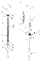
- Figure 1 is a simplified partial cross-sectional view of a stent delivery apparatus having a stent loaded therein, which can be used with a stent made in accordance with the present invention.
- Figure 2 is a view similar to that of figure 1 but showing an enlarged view of the distal end of the apparatus.
- Figure 3 is a perspective view of a stent made in accordance with the present invention, showing the stent in its compressed state.
- Figure 4 is a sectional, flat view of the stent shown in Figure 1.
- Figure 4A is an enlarged view of section of the stent shown in Figure 4.
- Figure 5 is a perspective view of the stent shown in Figure 1 but showing it in its expanded state.
- Figure 6 is an enlarged sectional view of the stent shown in Figure 5.
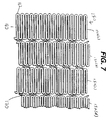
- Figure 7 is a view similar to that of Figure 4 but showing an alternative embodiment of the present invention.
- a stent 50 made in accordance with the present invention is shown in Figures 3 and 4, a stent 50 made in accordance with the present invention.
- Stent 50 is preferably made from a superelastic alloy such as Nitinol.
- stent 50 is made from an alloy comprising from about 50.5% (as used herein these percentages refer to atomic percentages) Ni to about 60% Ni, and most preferably about 55% Ni, with the remainder of the alloy Ti.
- the stent is such that it is superelastic at body temperature, and preferably has an Af in the range from about 24° C to about 37° C.
- the superelastic design of the stent makes it crush recoverable which, as discussed above, can be used as a stent or frame for any number of vascular devices for different applications.
- Stent 50 is a tubular member having front and back open ends 81 and 82 and a longitudinal axis 83 extending therebetween.
- the tubular member has a first smaller diameter, figures 3 and 4, for insertion into a patient and navigation through the vessels, and a second larger diameter, figures 5 and 6, for deployment into the target area of a vessel.
- the tubular member is made from a plurality of adjacent hoops 52, figure 1 showing hoops 52(a) - 52(b), extending between the front and back ends 81 and 82.
- the hoops 52 include a plurality of longitudinal struts 60 and a plurality of loops 62 connecting adjacent struts, wherein adjacent struts are connected at opposite ends so as to form an S or Z shape pattern.
- the loops 62 are curved substantially semi-circular and symmetrical sections having centers 64.
- Stent 50 further includes a plurality of bridges 70 which connect adjacent hoops 52 which can best be described by referring to Figure 4.
- Each bridge has two ends 56 and 58.
- the bridges have one end attached to one strut and/or loop, another end attached to a strut and/or loop on an adjacent hoop.
- Bridges 70 connect adjacent struts together at bridge to loop connection points 72 and 74.
- end 56 is connected to loop 64(a) at bridge to loop connection point 72
- end 58 is connected to loop 64(b) at bridge to loop connection point 74.
- Each bridge to loop connection points have centers 76.
- the bridge to loop connection points are separated angularly with respect to the longitudinal axis. That is the connection points are not immediately opposite each other. One could not draw a straight line between the connection points, wherein such line would be parallel to the longitudinal axis of the stent.
- each hoop has between 24 to 36 or more struts.
- the stent has a ratio of number of struts per hoop to strut length L (in inches) which is greater than 200. The length of a strut is measured in its compressed state parallel to the longitudinal axis 83 of the stent.
- the geometry of the stent changes quite significantly as a stent is deployed from its un-expanded state to its expanded state.
- the strut angle and strain levels in the loops and bridges are effected.
- all of the stent features will strain in a predictable manor so that the stent is reliable and uniform in strength.
- the stent sits in the delivery system in its un-expanded state as shown in Figure 4.
- Nitinol stents made from wire deploy in much the same manor and are dependent upon the same design constraints as laser cut stents.
- Stainless steel stents deploy similarly in terms of geometric changes as they are assisted with forces from balloons or other devices.
- the present invention utilizes structural geometry's which distribute strain to areas of the stent which are less susceptible to failure than others.
- one of the most vulnerable areas of the stent is the inside radius of the connecting loops.
- the connecting loops undergo the most deformation of all the stent features.
- the inside radius of the loop would normally be the area with the highest level of strain on the stent. This area is also critical in that it is usually the smallest radius on the stent.
- Stress concentrations are generally controlled or minimized by maintaining the largest radii possible.
- One way to accomplish this is to utilize the largest possible radii while maintaining feature widths which are consistent with applied forces.
- Another consideration is to minimize the maximum open area of the stent. Efficient utilization of the original tube from which the stent is cut increases stent strength and it's ability to trap embolic material.
- This feature allows for maximum utilization of Ni-Ti or other material capabilities to enhance radial strength, improve stent strength uniformity, improves fatigue life by minimizing local strain levels, allows for smaller open areas which enhance entrapment of embolic material, and improves stent apposition in irregular vessel wall shapes and curves.
- stent 50 has strut connecting loops 62 having a width W4, as measured at the center 64 parallel to axis 83, which are greater than the strut widths W2, as measured perpendicular to axis 83 itself.
- the thickness of the loops vary so that they are thickest near their centers This increases strain deformation at the strut and reduces the maximum strain levels at the extreme radii of the loop. This reduces the risk of stent failure and allows us to maximize radial strength properties.
- the feature is particularly advantageous for stents having large expansion ratios, which in turn requires them to have extreme bending requirements where large elastic strains are required.
- Nitinol can withstand extremely large amounts of elastic strain deformation, so the above features are well suited to stents made from this alloy. This feature allows for maximum utilization of Ni-Ti or other material capabilities to enhance radial strength, improve stent strength uniformity, improves fatigue life by minimizing local strain levels, allows for smaller open areas which enhance entrapment of embolic material, and improves stent apposition in irregular vessel wall shapes and curves.
- bridge geometry changes as a stent is deployed from its compressed state to its expanded state and vise-versa.
- strut angle and loop strain is effected. Since the bridges are connected to either the loops, struts or both, they are effected. twisting of one end of the stent with respect to the other, while loaded in the stent delivery system, should be avoided. Local torque delivered to the bridge ends displaces the bridge geometry. If the bridge design is duplicated around the stent perimeter, this displacement causes rotational shifting of the two loops being connected by the bridges. If the bridge design is duplicated throughout the stent, as in the present invention, this shift will occur down the length of the stent.
- a stent delivery system such as the one described below, will deploy the distal end first, then allow the proximal end to expand. It would be undesirable to allow the distal end to anchor into the vessel wall while holding the stent fixed in rotation, then release the proximal end. this could cause the stent to twist or whip in rotation to equilibrium after it is at least partially deployed within the vessel. Such whipping action could cause damage to the vessel.
- one embodiment of the present invention reduces the chance of such events from happening when deploying the stent.
- the rotational shift of the Z-sections can be made to alternate and will minimize large rotational changes between any two points on a given stent during deployment or constraint. That is the bridges connecting loop 52(b) to loop 52(c) are angled upwardly from left to right, while the bridges connecting loop 52(c) to loop 52(d) are angled downwardly from left to right. This alternating pattern is repeated down the length of the stent.
- This alternating pattern of bridge slopes improves the torsional characteristics of the stent so as to minimize any twisting or rotation of the stent with respect to any two hoops.
- This alternating bridge slope is particularly beneficial if the stent starts to twist in vivo. As the stent twists, the diameter of the stent will change. Alternating bridge slopes tend to minimize this effect. The diameter of a stent having bridges which are all sloped in the same direction will tend grow if twisted in one direction and shrink if twisted in the other direction. With alternating bridge slopes this effect is minimized and localized.
- the feature is particularly advantageous for stents having large expansion ratios, which in turn requires them to have extreme bending requirements where large elastic strains are required.
- Nitinol can withstand extremely large amounts of elastic strain deformation, so the above features are well suited to stents made from this alloy.
- This feature allows for maximum utilization of Ni-Ti or other material capabilities to enhance radial strength, improve stent strength uniformity, improves fatigue life by minimizing local strain levels, allows for smaller open areas which enhance entrapment of embolic material, and improves stent apposition in irregular vessel wall shapes and curves.
- stents are laser cut from small diameter tubing.
- this manufacturing process lead to designs with geometric features, such as struts, loops and bridges, having axial widths W2, W4 and W3 (respectively) which are larger than the tube wall thickness T (shown in Figure 5).
- W2, W4 and W3 axial widths
- W3 axial widths
- W2 and W4 axial widths
- W3 axial widths
- T shown in Figure 5
- the individual bridges, loops and struts which have widths greater than their thickness, they have a greater resistance to this in-plane bending than they do to out of plane bending. Because of this, the bridges and struts tend to twist, so that the stent as a whole can bend more easily. This twisting is a buckling condition which is unpredictable and can cause potentially high strain.
- This feature allows for maximum utilization of Ni-Ti or other material capabilities to enhance radial strength, improve stent strength uniformity, improves fatigue life by minimizing local strain levels, allows for smaller open areas which enhance entrapment of embolic material, and improves stent apposition in irregular vessel wall shapes and curves.
- FIG. 7 shows stent 150 which is similar to stent 50 shown in the previous drawings.
- Stent 150 is made from a plurality of adjacent hoops 152, figure 7 showing hoops 152(a) - 152(d).
- the hoops 152 include a plurality of longitudinal struts 160 and a plurality of loops 162 connecting adjacent struts, wherein adjacent struts are connected at opposite ends so as to form an S or Z shape pattern.
- Stent 150 further includes a plurality of bridges 170 which connect adjacent hoops 152. As seen from the figure, bridges 170 are non-linear and curve between adjacent hoops.
- the stent of the present invention be made from a superelastic alloy and most preferably made of an alloy material having greater than 50.5 atomic % Nickel and the balance titanium. Greater than 50.5 atomic % Nickel allows for an alloy in which the temperature at which the martensite phase transforms completely to the austenite phase (the Af temperature) is below human body temperature and preferably is about 24° C to about 37°C so that austenite is the only stable phase at body temperature.
- Nitinol tubing is commercially available from a number of suppliers including Nitinol Devices and Components, Fremont CA.
- the tubular member is then loaded into a machine which will cut the predetermined pattern of the stent, which was discussed above and is shown in the figures, into the tube.
- Machines for cutting patterns in tubular devices to make stents or the like are well known to those of ordinary skill in the art and are commercially available.
- Such machines typically hold the metal tube between the open ends while a cutting laser, preferably under microprocessor control, cuts the pattern.
- the pattern dimensions and styles, laser positioning requirements, and other information are programmed into a microprocessor which controls all aspects of the process.
- the stent pattern is cut, the stent is treated and polished using any number of methods well known to those skilled in the art. Lastly, the stent is then cooled until it is completely martensitic, crimped down to its un-expanded diameter and then loaded into the sheath of the delivery apparatus.
- FIGS 1 and 2 show a self-expanding stent delivery apparatus 1 for a stent made in accordance with the present invention.
- Apparatus 1 comprises inner and outer coaxial tubes.
- the inner tube is called the shaft 10 and the outer tube is called the sheath 40.
- Shaft 10 has proximal and distal ends 12 and 14 respectively. the distal end 14 of the shaft terminates at a luer lock hub 5.
- shaft 10 has a proximal portion 16 which is made from a relatively stiff material such as stainless steel, Nitinol, or any other suitable material, and an distal portion 18 which is made from a polyethylene, polyimide, pellethane, Pebax, Vestamid, Cristamid, Grillamid or any other suitable material known to those of ordinary skill in the art..
- the two portions are joined together by any number of means known to those of ordinary skill in the art.
- the stainless steel proximal end gives the shaft the necessary rigidity or stiffness it needs to effectively push out the stent, while the polymeric distal portion provides the necessary flexibility to navigate tortuous vessels.
- the distal portion 18 of the shaft has a distal tip 20 attached thereto.
- the distal tip 20 has a proximal end 34 whose diameter is substantially the same as the outer diameter of the sheath 40.
- the distal tip tapers to a smaller diameter from its proximal end to its distal end, wherein the distal end 36 of the distal tip has a diameter smaller than the inner diameter of the sheath.
- a stop 22 which is proximal to the distal tip 20. Stop 22 can be made from any number of materials known in the art, including stainless steel, and is even more preferably made from a highly radiopaque material such as platinum, gold tantalum.
- stop 22 is substantially the same as the inner diameter of sheath 40, and would actually make frictional contact with the inner surface of the sheath. Stop 22 helps to push the stent out of the sheath during deployment, and helps the stent from migrating proximally into the sheath 40.
- a stent bed 24 is defined as being that portion of the shaft between the distal tip 20 and the stop 22.
- the stent bed 24 and the stent 50 are coaxial so that the portion of shaft 18 comprising the stent bed 24 is located within the lumen of the stent 50. However, the stent bed 24 does not make any contact with stent 50 itself.
- shaft 10 has a guidewire lumen 28 extending along its length from its proximal end 12 and exiting through its distal tip 20. This allows the shaft 10 to receive a guidewire much in the same way that an ordinary balloon angioplastly catheter receives a guidewire.
- Such guidewires are well known in art and help guide catheters and other medical devices through the vasculature-of the body.
- Sheath 40 is preferably a polymeric catheter and has a proximal end 42 terminating at a hub 52. Sheath 40 also has a distal end 44 which terminates at the proximal end 34 of distal tip 20 of the shaft 18, when the stent is in its fully un-deployed position as shown in the figures.
- the distal end 44 of sheath 40 includes a radiopaque marker band 46 disposed along its outer surface. As will be explained below, the stent is fully deployed when the marker band 46 is lined up with radiopaque stop 22, thus indicating to the physician that it is now safe to remove the apparatus 1 from the body.
- Sheath 40 preferably comprises an outer polymeric layer and an inner polymeric layer.
- Braided reinforcing layer is preferably made from stainless steel.
- the use of braided reinforcing layers in other types of medical devices can be found in U.S. patents 3,585,707 issued to Stevens on June 22, 1971, 5,045,072 issued to Castillo et al. on September 3, 1991, and 5,254,107 issued to Soltesz on October 19, 1993, all of which are hereby incorporated herein by reference.
- Figures 1 and 2 show the stent 50 as being in its fully un-deployed position. This is the position the stent is in when the apparatus 1 is inserted into the vasculature and its distal end is navigated to a target site.
- Stent 50 is disposed around stent bed 24 and at the distal end 44 of sheath 40.
- the distal tip 20 of the shaft 10 is distal to the distal end 44 of the sheath 40, and the proximal end 12 of the shaft 10 is proximal to the proximal end 42 of the sheath 40.
- the start 50 is in a compressed state and makes frictional contact with the inner surface 48 of the sheath 40.
- sheath 40 and shaft 10 are locked together at their proximal ends by a Touhy Borst valve 8. This prevents any sliding movement between the shaft and sheath which could result in a premature deployment or partial deployment of the stent.
- the Touhy Borst valve 8 is opened so that that the sheath 40 and shaft 10 are no longer locked together.
- apparatus 1 deploys stent 50 should be readily apparent.
- the apparatus 1 is first inserted into a vessel so that the stent bed 24 is at a target diseased site. Once this has occurred the physician would open the Touhy Borst valve 8. The physician would then grasp the proximal end 12 of shaft 10 so as to hold it in place. Thereafter, the physician would grasp the proximal end 42 of sheath 40 and slide it proximal, relative to the shaft 40. Stop 22 prevents the stent 50 from sliding back with the sheath 40, so that as the sheath 40 is moved back, the stent 50 is pushed out of the distal end 44 of the sheath 40. Stent deployment is complete when the radiopaque band 46 on the sheath 40 is proximal to radiopaque stop 22. The apparatus 1 can now be withdrawn through stent 50 and removed from the patient.
Applications Claiming Priority (2)
| Application Number | Priority Date | Filing Date | Title |
|---|---|---|---|
| US5402 | 1979-01-22 | ||
| US09/005,402 US6342067B1 (en) | 1998-01-09 | 1998-01-09 | Intravascular stent having curved bridges for connecting adjacent hoops |
Publications (2)
| Publication Number | Publication Date |
|---|---|
| EP0928606A1 true EP0928606A1 (en) | 1999-07-14 |
| EP0928606B1 EP0928606B1 (en) | 2010-03-03 |
Family
ID=21715673
Family Applications (1)
| Application Number | Title | Priority Date | Filing Date |
|---|---|---|---|
| EP99300135A Expired - Lifetime EP0928606B1 (en) | 1998-01-09 | 1999-01-08 | An intravascular stent having curved bridges for connecting adjacent hoops |
Country Status (6)
| Country | Link |
|---|---|
| US (1) | US6342067B1 (es) |
| EP (1) | EP0928606B1 (es) |
| JP (2) | JP4675440B2 (es) |
| AU (1) | AU742914B2 (es) |
| CA (1) | CA2257750C (es) |
| DE (1) | DE69942076D1 (es) |
Cited By (30)
| Publication number | Priority date | Publication date | Assignee | Title |
|---|---|---|---|---|
| EP0928605A3 (en) * | 1998-01-09 | 2000-03-22 | Nitinol Development Corporation | An intravascular stent having an improved strut configuration |
| WO2000042945A1 (en) * | 1999-01-22 | 2000-07-27 | Al Saadon Khalid | Expandable endovascular medical tubular stent |
| FR2813785A1 (fr) | 2000-09-08 | 2002-03-15 | Cathnet Science Holding As | Endoprothese extensible |
| WO2002076349A1 (en) * | 2001-03-21 | 2002-10-03 | Cordis Corporation | Stent-based venous valves |
| US6478813B1 (en) | 1997-08-01 | 2002-11-12 | Peter T. Keith | Method for joining grafts in a common body passageway |
| US6482227B1 (en) | 1998-03-30 | 2002-11-19 | Cordis Corporation | Stent graft having improved attachment within a body vessel |
| US6575994B1 (en) | 1994-02-10 | 2003-06-10 | Teramed, Inc. | Method and apparatus concerning bypass grafts |
| EP1325715A2 (en) | 2002-01-08 | 2003-07-09 | Cordis Corporation | Extension prosthesis for an arterial repair |
| EP1325716A1 (en) | 2002-01-08 | 2003-07-09 | Cordis Corporation | Thoracic aneurysm repair prosthesis and system |
| EP1325717A2 (en) | 2002-01-08 | 2003-07-09 | Cordis Corporation | Stent graft with branch leg |
| EP1121911A3 (en) * | 2000-02-01 | 2003-07-30 | Cordis Corporation | A self-expanding stent-graft |
| EP1332728A1 (en) | 2002-01-08 | 2003-08-06 | Cordis Corporation | Supra-renal prosthesis and renal artery bypass |
| US6626938B1 (en) | 2000-11-16 | 2003-09-30 | Cordis Corporation | Stent graft having a pleated graft member |
| DE10213369A1 (de) * | 2002-03-21 | 2003-10-02 | Biotronik Mess & Therapieg | Stent |
| EP1459707A1 (en) * | 2003-03-20 | 2004-09-22 | Cordis Corporation | Anvil bridge stent design |
| DE10334868A1 (de) * | 2003-07-29 | 2005-03-03 | pfm Produkte für die Medizin AG | Implantierbare Einrichtung als Organklappenersatz |
| US6935404B2 (en) | 1998-01-09 | 2005-08-30 | Thomas Duerig | Intravascular device with improved radiopacity |
| WO2005104991A1 (en) | 2004-05-05 | 2005-11-10 | Invatec S.R.L. | Endoluminal prosthesis |
| WO2006024488A2 (en) | 2004-08-30 | 2006-03-09 | Interstitial Therapeutics | Medical stent provided with inhibitors of atp synthesis |
| US7070616B2 (en) | 2003-10-31 | 2006-07-04 | Cordis Corporation | Implantable valvular prosthesis |
| EP1719474A2 (en) | 2002-01-08 | 2006-11-08 | Cordis Corporation | Bilateral extension prosthesis |
| US7189255B2 (en) | 2003-10-28 | 2007-03-13 | Cordis Corporation | Prosthesis support ring assembly |
| US7270675B2 (en) | 2002-05-10 | 2007-09-18 | Cordis Corporation | Method of forming a tubular membrane on a structural frame |
| US7347869B2 (en) | 2003-10-31 | 2008-03-25 | Cordis Corporation | Implantable valvular prosthesis |
| US7351256B2 (en) | 2002-05-10 | 2008-04-01 | Cordis Corporation | Frame based unidirectional flow prosthetic implant |
| US7485141B2 (en) | 2002-05-10 | 2009-02-03 | Cordis Corporation | Method of placing a tubular membrane on a structural frame |
| JP2009526595A (ja) * | 2006-02-17 | 2009-07-23 | インヴァテック エス.アール.エル. | 内腔プロテーゼ |
| US7758632B2 (en) | 2002-05-10 | 2010-07-20 | Cordis Corporation | Frame based unidirectional flow prosthetic implant |
| US9028540B2 (en) | 2011-03-25 | 2015-05-12 | Covidien Lp | Vascular stent with improved vessel wall apposition |
| US9254205B2 (en) | 2012-09-27 | 2016-02-09 | Covidien Lp | Vascular stent with improved vessel wall apposition |
Families Citing this family (128)
| Publication number | Priority date | Publication date | Assignee | Title |
|---|---|---|---|---|
| RU2089131C1 (ru) * | 1993-12-28 | 1997-09-10 | Сергей Апполонович Пульнев | Стент |
| US20070073384A1 (en) * | 1995-03-01 | 2007-03-29 | Boston Scientific Scimed, Inc. | Longitudinally flexible expandable stent |
| US7204848B1 (en) | 1995-03-01 | 2007-04-17 | Boston Scientific Scimed, Inc. | Longitudinally flexible expandable stent |
| US20040106985A1 (en) * | 1996-04-26 | 2004-06-03 | Jang G. David | Intravascular stent |
| US6330884B1 (en) * | 1997-11-14 | 2001-12-18 | Transvascular, Inc. | Deformable scaffolding multicellular stent |
| US5938697A (en) * | 1998-03-04 | 1999-08-17 | Scimed Life Systems, Inc. | Stent having variable properties |
| EP1132058A1 (en) | 2000-03-06 | 2001-09-12 | Advanced Laser Applications Holding S.A. | Intravascular prothesis |
| US6616689B1 (en) | 2000-05-03 | 2003-09-09 | Advanced Cardiovascular Systems, Inc. | Intravascular stent |
| US6602282B1 (en) * | 2000-05-04 | 2003-08-05 | Avantec Vascular Corporation | Flexible stent structure |
| US6492615B1 (en) * | 2000-10-12 | 2002-12-10 | Scimed Life Systems, Inc. | Laser polishing of medical devices |
| US8038708B2 (en) | 2001-02-05 | 2011-10-18 | Cook Medical Technologies Llc | Implantable device with remodelable material and covering material |
| US6955686B2 (en) * | 2001-03-01 | 2005-10-18 | Cordis Corporation | Flexible stent |
| AU784552B2 (en) * | 2001-03-02 | 2006-05-04 | Cardinal Health 529, Llc | Flexible stent |
| US6602283B2 (en) * | 2001-04-06 | 2003-08-05 | Scimed Life Systems, Inc. | Stent design |
| US7717708B2 (en) * | 2001-04-13 | 2010-05-18 | Orametrix, Inc. | Method and system for integrated orthodontic treatment planning using unified workstation |
| US20050021123A1 (en) * | 2001-04-30 | 2005-01-27 | Jurgen Dorn | Variable speed self-expanding stent delivery system and luer locking connector |
| US6800090B2 (en) * | 2001-05-14 | 2004-10-05 | Cardiac Dimensions, Inc. | Mitral valve therapy device, system and method |
| US6676702B2 (en) * | 2001-05-14 | 2004-01-13 | Cardiac Dimensions, Inc. | Mitral valve therapy assembly and method |
| US6939373B2 (en) * | 2003-08-20 | 2005-09-06 | Advanced Cardiovascular Systems, Inc. | Intravascular stent |
| US6629994B2 (en) | 2001-06-11 | 2003-10-07 | Advanced Cardiovascular Systems, Inc. | Intravascular stent |
| US6949122B2 (en) * | 2001-11-01 | 2005-09-27 | Cardiac Dimensions, Inc. | Focused compression mitral valve device and method |
| US7311729B2 (en) | 2002-01-30 | 2007-12-25 | Cardiac Dimensions, Inc. | Device and method for modifying the shape of a body organ |
| US7635387B2 (en) * | 2001-11-01 | 2009-12-22 | Cardiac Dimensions, Inc. | Adjustable height focal tissue deflector |
| US6824562B2 (en) | 2002-05-08 | 2004-11-30 | Cardiac Dimensions, Inc. | Body lumen device anchor, device and assembly |
| US7179282B2 (en) * | 2001-12-05 | 2007-02-20 | Cardiac Dimensions, Inc. | Device and method for modifying the shape of a body organ |
| US6908478B2 (en) * | 2001-12-05 | 2005-06-21 | Cardiac Dimensions, Inc. | Anchor and pull mitral valve device and method |
| US6976995B2 (en) * | 2002-01-30 | 2005-12-20 | Cardiac Dimensions, Inc. | Fixed length anchor and pull mitral valve device and method |
| US6793673B2 (en) | 2002-12-26 | 2004-09-21 | Cardiac Dimensions, Inc. | System and method to effect mitral valve annulus of a heart |
| US20050209690A1 (en) * | 2002-01-30 | 2005-09-22 | Mathis Mark L | Body lumen shaping device with cardiac leads |
| US6960229B2 (en) * | 2002-01-30 | 2005-11-01 | Cardiac Dimensions, Inc. | Device and method for modifying the shape of a body organ |
| US7351260B2 (en) * | 2005-01-20 | 2008-04-01 | Cardiac Dimensions, Inc. | Tissue shaping device |
| US7004958B2 (en) * | 2002-03-06 | 2006-02-28 | Cardiac Dimensions, Inc. | Transvenous staples, assembly and method for mitral valve repair |
| US6797001B2 (en) * | 2002-03-11 | 2004-09-28 | Cardiac Dimensions, Inc. | Device, assembly and method for mitral valve repair |
| US7288111B1 (en) * | 2002-03-26 | 2007-10-30 | Thoratec Corporation | Flexible stent and method of making the same |
| AU2003239369A1 (en) * | 2002-05-06 | 2003-11-17 | Abbott Laboratories | Endoprosthesis for controlled contraction and expansion |
| CA2950492C (en) * | 2002-05-08 | 2018-12-04 | Cardiac Dimensions Pty. Ltd. | Device and method for modifying the shape of a body organ |
| EP1503700B1 (en) * | 2002-05-08 | 2012-09-26 | Abbott Laboratories | Endoprosthesis having foot extensions |
| US6656220B1 (en) | 2002-06-17 | 2003-12-02 | Advanced Cardiovascular Systems, Inc. | Intravascular stent |
| US6969402B2 (en) * | 2002-07-26 | 2005-11-29 | Syntheon, Llc | Helical stent having flexible transition zone |
| US9561123B2 (en) | 2002-08-30 | 2017-02-07 | C.R. Bard, Inc. | Highly flexible stent and method of manufacture |
| US6878162B2 (en) * | 2002-08-30 | 2005-04-12 | Edwards Lifesciences Ag | Helical stent having improved flexibility and expandability |
| US20040054398A1 (en) * | 2002-09-13 | 2004-03-18 | Cully Edward H. | Stent device with multiple helix construction |
| US7837729B2 (en) * | 2002-12-05 | 2010-11-23 | Cardiac Dimensions, Inc. | Percutaneous mitral valve annuloplasty delivery system |
| US7316708B2 (en) * | 2002-12-05 | 2008-01-08 | Cardiac Dimensions, Inc. | Medical device delivery system |
| US7314485B2 (en) * | 2003-02-03 | 2008-01-01 | Cardiac Dimensions, Inc. | Mitral valve device using conditioned shape memory alloy |
| WO2004071343A2 (en) * | 2003-02-11 | 2004-08-26 | Cook, Inc. | Removable vena cava filter |
| US20040158321A1 (en) * | 2003-02-12 | 2004-08-12 | Cardiac Dimensions, Inc. | Method of implanting a mitral valve therapy device |
| US7625399B2 (en) * | 2003-04-24 | 2009-12-01 | Cook Incorporated | Intralumenally-implantable frames |
| WO2004096100A1 (en) | 2003-04-24 | 2004-11-11 | Cook Incorporated | Artificial valve prosthesis with improved flow dynamics |
| US7717952B2 (en) * | 2003-04-24 | 2010-05-18 | Cook Incorporated | Artificial prostheses with preferred geometries |
| US7658759B2 (en) * | 2003-04-24 | 2010-02-09 | Cook Incorporated | Intralumenally implantable frames |
| US20040220654A1 (en) * | 2003-05-02 | 2004-11-04 | Cardiac Dimensions, Inc. | Device and method for modifying the shape of a body organ |
| US20060161169A1 (en) * | 2003-05-02 | 2006-07-20 | Cardiac Dimensions, Inc., A Delaware Corporation | Device and method for modifying the shape of a body organ |
| US7625401B2 (en) * | 2003-05-06 | 2009-12-01 | Abbott Laboratories | Endoprosthesis having foot extensions |
| US7625398B2 (en) * | 2003-05-06 | 2009-12-01 | Abbott Laboratories | Endoprosthesis having foot extensions |
| US7351259B2 (en) * | 2003-06-05 | 2008-04-01 | Cardiac Dimensions, Inc. | Device, system and method to affect the mitral valve annulus of a heart |
| US7887582B2 (en) * | 2003-06-05 | 2011-02-15 | Cardiac Dimensions, Inc. | Device and method for modifying the shape of a body organ |
| US6916336B2 (en) * | 2003-06-09 | 2005-07-12 | Avantec Vascular Corporation | Vascular prosthesis |
| US7131993B2 (en) * | 2003-06-25 | 2006-11-07 | Boston Scientific Scimed, Inc. | Varying circumferential spanned connectors in a stent |
| US7794496B2 (en) * | 2003-12-19 | 2010-09-14 | Cardiac Dimensions, Inc. | Tissue shaping device with integral connector and crimp |
| US9526616B2 (en) | 2003-12-19 | 2016-12-27 | Cardiac Dimensions Pty. Ltd. | Mitral valve annuloplasty device with twisted anchor |
| US7837728B2 (en) * | 2003-12-19 | 2010-11-23 | Cardiac Dimensions, Inc. | Reduced length tissue shaping device |
| US20050137449A1 (en) * | 2003-12-19 | 2005-06-23 | Cardiac Dimensions, Inc. | Tissue shaping device with self-expanding anchors |
| US20050137450A1 (en) * | 2003-12-19 | 2005-06-23 | Cardiac Dimensions, Inc., A Washington Corporation | Tapered connector for tissue shaping device |
| EP1737382B1 (en) * | 2004-04-16 | 2011-03-30 | Cook Incorporated | Removable vena cava filter for reduced trauma in collapsed configuration |
| US8043322B2 (en) * | 2004-04-16 | 2011-10-25 | Cook Medical Technologies Llc | Removable vena cava filter having inwardly positioned anchoring hooks in collapsed configuration |
| AU2005235315B2 (en) * | 2004-04-16 | 2010-09-09 | Cook, Inc. | Removable vena cava filter with anchoring feature for reduced trauma |
| WO2005102213A1 (en) | 2004-04-16 | 2005-11-03 | Cook, Inc. | Removable vena cava filter having primary struts for enhanced retrieval and delivery |
| US20050273151A1 (en) * | 2004-06-04 | 2005-12-08 | John Fulkerson | Stent delivery system |
| MX2007000349A (es) * | 2004-06-30 | 2007-06-25 | Johnson & Johnson | Dispositivo medico intraluminal que tiene elementos asimetricos y metodo para optimizacion. |
| US7780721B2 (en) | 2004-09-01 | 2010-08-24 | C. R. Bard, Inc. | Stent and method for manufacturing the stent |
| US20060064155A1 (en) * | 2004-09-01 | 2006-03-23 | Pst, Llc | Stent and method for manufacturing the stent |
| EP1802252B1 (en) * | 2004-09-27 | 2011-07-20 | Cook, Inc. | Removable vena cava filter |
| WO2006036912A2 (en) * | 2004-09-27 | 2006-04-06 | Echobio Llc | Systems, apparatus and methods related to helical, non-helical or removable stents with rectilinear ends |
| FR2881946B1 (fr) * | 2005-02-17 | 2008-01-04 | Jacques Seguin | Dispositif permettant le traitement de conduits corporels au niveau d'une bifurcation |
| EP2364676B1 (en) | 2005-06-30 | 2018-12-19 | Abbott Laboratories | Endoprosthesis having foot extensions |
| ATE526911T1 (de) * | 2005-08-17 | 2011-10-15 | Bard Inc C R | Stenteinbringungssystem mit variabler geschwindigkeit |
| US20070250148A1 (en) * | 2005-09-26 | 2007-10-25 | Perry Kenneth E Jr | Systems, apparatus and methods related to helical, non-helical or removable stents with rectilinear ends |
| US7867176B2 (en) * | 2005-12-27 | 2011-01-11 | Cordis Corporation | Variable stiffness guidewire |
| US11026822B2 (en) | 2006-01-13 | 2021-06-08 | C. R. Bard, Inc. | Stent delivery system |
| EP1971299B1 (en) | 2006-01-13 | 2014-07-16 | C.R. Bard, Inc. | Stent delivery system |
| US20070191926A1 (en) * | 2006-02-14 | 2007-08-16 | Advanced Cardiovascular Systems, Inc. | Stent pattern for high stent retention |
| US9456911B2 (en) * | 2006-02-14 | 2016-10-04 | Angiomed Gmbh & Co. Medizintechnik | Highly flexible stent and method of manufacture |
| US7785317B2 (en) | 2006-03-29 | 2010-08-31 | Codman & Shurtleff, Inc. | Joined metal tubing and method of manufacture |
| US7503932B2 (en) * | 2006-04-11 | 2009-03-17 | Cardiac Dimensions, Inc. | Mitral valve annuloplasty device with vena cava anchor |
| US8690938B2 (en) * | 2006-05-26 | 2014-04-08 | DePuy Synthes Products, LLC | Occlusion device combination of stent and mesh with diamond-shaped porosity |
| US8118859B2 (en) * | 2006-05-26 | 2012-02-21 | Codman & Shurtleff, Inc. | Occlusion device combination of stent and mesh having offset parallelogram porosity |
| US7766935B2 (en) | 2006-06-12 | 2010-08-03 | Codman & Shurtleff, Inc. | Modified headpiece for hydraulic coil deployment system |
| US7670353B2 (en) * | 2006-06-12 | 2010-03-02 | Codman & Shurtleff, Inc. | Modified headpiece for hydraulic coil deployment system |
| US8585732B2 (en) * | 2006-06-14 | 2013-11-19 | DePuy Synthes Products, LLC | Retrieval device with sidewall grippers |
| US11285005B2 (en) | 2006-07-17 | 2022-03-29 | Cardiac Dimensions Pty. Ltd. | Mitral valve annuloplasty device with twisted anchor |
| GB0615658D0 (en) * | 2006-08-07 | 2006-09-13 | Angiomed Ag | Hand-held actuator device |
| US7988720B2 (en) | 2006-09-12 | 2011-08-02 | Boston Scientific Scimed, Inc. | Longitudinally flexible expandable stent |
| US8778009B2 (en) * | 2006-10-06 | 2014-07-15 | Abbott Cardiovascular Systems Inc. | Intravascular stent |
| US7854849B2 (en) * | 2006-10-10 | 2010-12-21 | Multiphase Systems Integration | Compact multiphase inline bulk water separation method and system for hydrocarbon production |
| FR2911063B1 (fr) | 2007-01-09 | 2009-03-20 | Stentys S A S Soc Par Actions | Structure de pont ruptible pour un stent, et stent incluant de telles structures de pont. |
| US8333799B2 (en) | 2007-02-12 | 2012-12-18 | C. R. Bard, Inc. | Highly flexible stent and method of manufacture |
| US8328865B2 (en) * | 2007-02-12 | 2012-12-11 | C. R. Bard, Inc. | Highly flexible stent and method of manufacture |
| GB0713497D0 (en) * | 2007-07-11 | 2007-08-22 | Angiomed Ag | Device for catheter sheath retraction |
| US8398789B2 (en) | 2007-11-30 | 2013-03-19 | Abbott Laboratories | Fatigue-resistant nickel-titanium alloys and medical devices using same |
| US8246672B2 (en) * | 2007-12-27 | 2012-08-21 | Cook Medical Technologies Llc | Endovascular graft with separately positionable and removable frame units |
| US8091455B2 (en) | 2008-01-30 | 2012-01-10 | Cummins Filtration Ip, Inc. | Apparatus, system, and method for cutting tubes |
| US9005274B2 (en) * | 2008-08-04 | 2015-04-14 | Stentys Sas | Method for treating a body lumen |
| US8006594B2 (en) * | 2008-08-11 | 2011-08-30 | Cardiac Dimensions, Inc. | Catheter cutting tool |
| EP2352854A1 (en) | 2008-10-31 | 2011-08-10 | Fort Wayne Metals Research Products Corporation | Method for imparting improved fatigue strength to wire made of shape memory alloys, and medical devices made from such wire |
| US8246648B2 (en) * | 2008-11-10 | 2012-08-21 | Cook Medical Technologies Llc | Removable vena cava filter with improved leg |
| US8597343B2 (en) * | 2009-09-18 | 2013-12-03 | Medtronic Vascular, Inc. | Stent with constant stiffness along the length of the stent |
| CN106901881B (zh) * | 2009-10-30 | 2019-06-18 | 科迪斯公司 | 具有改进的柔性和耐用性的脉管内装置 |
| US8206434B2 (en) | 2010-03-02 | 2012-06-26 | Medtronic Vascular, Inc. | Stent with sinusoidal wave form and orthogonal end and method for making same |
| US20110218615A1 (en) * | 2010-03-02 | 2011-09-08 | Medtronic Vascular, Inc. | Stent With Multi-Crown Constraint and Method for Ending Helical Wound Stents |
| US8328072B2 (en) | 2010-07-19 | 2012-12-11 | Medtronic Vascular, Inc. | Method for forming a wave form used to make wound stents |
| GB201017834D0 (en) | 2010-10-21 | 2010-12-01 | Angiomed Ag | System to deliver a bodily implant |
| US10022212B2 (en) | 2011-01-13 | 2018-07-17 | Cook Medical Technologies Llc | Temporary venous filter with anti-coagulant delivery method |
| US9296034B2 (en) | 2011-07-26 | 2016-03-29 | Medtronic Vascular, Inc. | Apparatus and method for forming a wave form for a stent from a wire |
| EP2811939B8 (en) | 2012-02-10 | 2017-11-15 | CVDevices, LLC | Products made of biological tissues for stents and methods of manufacturing |
| US9242290B2 (en) | 2012-04-03 | 2016-01-26 | Medtronic Vascular, Inc. | Method and apparatus for creating formed elements used to make wound stents |
| US9238260B2 (en) | 2012-04-18 | 2016-01-19 | Medtronic Vascular, Inc. | Method and apparatus for creating formed elements used to make wound stents |
| US9364351B2 (en) | 2012-04-23 | 2016-06-14 | Medtronic Vascular, Inc. | Method for forming a stent |
| CN106667630B (zh) | 2012-05-14 | 2019-03-29 | C·R·巴德公司 | 可均匀膨胀的支架 |
| EP2953580A2 (en) | 2013-02-11 | 2015-12-16 | Cook Medical Technologies LLC | Expandable support frame and medical device |
| USD723165S1 (en) | 2013-03-12 | 2015-02-24 | C. R. Bard, Inc. | Stent |
| EP2868331B1 (de) * | 2013-11-01 | 2016-07-13 | ECP Entwicklungsgesellschaft mbH | Pumpe, insbesondere Blutpumpe |
| US11628077B2 (en) * | 2016-10-31 | 2023-04-18 | Razmodics Llc | Post deployment radial force recovery of biodegradable scaffolds |
| US10918504B2 (en) * | 2017-02-21 | 2021-02-16 | Silk Road Medical, Inc. | Vascular implant |
| US10390953B2 (en) | 2017-03-08 | 2019-08-27 | Cardiac Dimensions Pty. Ltd. | Methods and devices for reducing paravalvular leakage |
| US10238513B2 (en) | 2017-07-19 | 2019-03-26 | Abbott Cardiovascular Systems Inc. | Intravascular stent |
| CN114587704A (zh) * | 2017-09-12 | 2022-06-07 | W.L.戈尔及同仁股份有限公司 | 具有可旋转支柱的医疗装置基底 |
| WO2022132571A1 (en) | 2020-12-14 | 2022-06-23 | Cardiac Dimensions Pty. Ltd. | Modular pre-loaded medical implants and delivery systems |
Citations (9)
| Publication number | Priority date | Publication date | Assignee | Title |
|---|---|---|---|---|
| US3585707A (en) | 1966-04-13 | 1971-06-22 | Cordis Corp | Method of making tubular products |
| US4665771A (en) | 1984-10-15 | 1987-05-19 | Mitchell Frank R | Hypocyclic drive |
| US4665905A (en) | 1986-06-09 | 1987-05-19 | Brown Charles S | Dynamic elbow and knee extension brace |
| US4733665A (en) | 1985-11-07 | 1988-03-29 | Expandable Grafts Partnership | Expandable intraluminal graft, and method and apparatus for implanting an expandable intraluminal graft |
| US4925445A (en) | 1983-09-16 | 1990-05-15 | Fuji Terumo Co., Ltd. | Guide wire for catheter |
| US5045072A (en) | 1989-06-13 | 1991-09-03 | Cordis Corporation | Catheter having highly radiopaque, flexible tip |
| EP0491349A2 (en) * | 1990-12-18 | 1992-06-24 | Advanced Cardiovascular Systems, Inc. | Superelastic guiding member |
| EP0540290A2 (en) * | 1991-10-28 | 1993-05-05 | Advanced Cardiovascular Systems, Inc. | Expandable stents and method for making same |
| WO1997040783A2 (en) * | 1996-04-26 | 1997-11-06 | Jang G David | Intravascular stent |
Family Cites Families (21)
| Publication number | Priority date | Publication date | Assignee | Title |
|---|---|---|---|---|
| SE445884B (sv) | 1982-04-30 | 1986-07-28 | Medinvent Sa | Anordning for implantation av en rorformig protes |
| US4665906A (en) | 1983-10-14 | 1987-05-19 | Raychem Corporation | Medical devices incorporating sim alloy elements |
| JPH0226564A (ja) * | 1988-07-18 | 1990-01-29 | Nippon Zeon Co Ltd | 生体器官拡張器 |
| EP0565542B1 (en) * | 1991-01-04 | 1996-08-21 | American Medical Systems, Inc. | Resectable self-expanding stent |
| US5254107A (en) | 1991-03-06 | 1993-10-19 | Cordis Corporation | Catheter having extended braid reinforced transitional tip |
| FR2683449A1 (fr) | 1991-11-08 | 1993-05-14 | Cardon Alain | Endoprothese pour implantation transluminale. |
| EP0633798B1 (en) * | 1992-03-31 | 2003-05-07 | Boston Scientific Corporation | Vascular filter |
| US5449373A (en) * | 1994-03-17 | 1995-09-12 | Medinol Ltd. | Articulated stent |
| ES2126896T3 (es) | 1994-05-19 | 1999-04-01 | Scimed Life Systems Inc | Dispositivos mejorados de soporte de tejidos biologicos. |
| EP0792627B2 (en) | 1994-06-08 | 2003-10-29 | Cardiovascular Concepts, Inc. | System for forming a bifurcated graft |
| US5397355A (en) | 1994-07-19 | 1995-03-14 | Stentco, Inc. | Intraluminal stent |
| EP0758216B1 (en) * | 1995-03-01 | 2002-07-10 | SciMed Life Systems, Inc. | Improved longitudinally flexible expandable stent |
| WO1997000294A1 (en) | 1995-06-19 | 1997-01-03 | Shell Internationale Research Maatschappij B.V. | Free flowing powder composition |
| EP0842567B1 (en) | 1995-08-03 | 1999-03-31 | Nortel Networks Corporation | Synchronization to pseudo random number sequence with sign ambiguity in communications systems |
| JP2000501904A (ja) | 1995-08-03 | 2000-02-15 | テレフオンアクチーボラゲツト エル エム エリクソン(パブル) | ワイヤレスマルチセル無線通信システム |
| GB9516158D0 (en) | 1995-08-07 | 1995-10-04 | Stc Submarine Systems Ltd | Switching control circuit for branching units |
| AUPN483395A0 (en) | 1995-08-16 | 1995-09-07 | Commonwealth Scientific And Industrial Research Organisation | Die casting devices |
| GB9517055D0 (en) | 1995-08-19 | 1995-10-25 | Normalair Garrett Ltd | Apparatus and method for moving gas |
| US5830179A (en) * | 1996-04-09 | 1998-11-03 | Endocare, Inc. | Urological stent therapy system and method |
| DE69738786D1 (de) * | 1996-05-08 | 2008-07-31 | Sorin Biomedica Cardio Srl | Ein Stent für Angioplastie |
| WO1998020810A1 (en) | 1996-11-12 | 1998-05-22 | Medtronic, Inc. | Flexible, radially expansible luminal prostheses |
-
1998
- 1998-01-09 US US09/005,402 patent/US6342067B1/en not_active Expired - Lifetime
-
1999
- 1999-01-04 CA CA002257750A patent/CA2257750C/en not_active Expired - Lifetime
- 1999-01-07 AU AU10064/99A patent/AU742914B2/en not_active Expired
- 1999-01-08 EP EP99300135A patent/EP0928606B1/en not_active Expired - Lifetime
- 1999-01-08 JP JP346399A patent/JP4675440B2/ja not_active Expired - Lifetime
- 1999-01-08 DE DE69942076T patent/DE69942076D1/de not_active Expired - Lifetime
-
2008
- 2008-09-24 JP JP2008243682A patent/JP5208641B2/ja not_active Expired - Lifetime
Patent Citations (11)
| Publication number | Priority date | Publication date | Assignee | Title |
|---|---|---|---|---|
| US3585707A (en) | 1966-04-13 | 1971-06-22 | Cordis Corp | Method of making tubular products |
| US4925445A (en) | 1983-09-16 | 1990-05-15 | Fuji Terumo Co., Ltd. | Guide wire for catheter |
| US4665771A (en) | 1984-10-15 | 1987-05-19 | Mitchell Frank R | Hypocyclic drive |
| US4733665A (en) | 1985-11-07 | 1988-03-29 | Expandable Grafts Partnership | Expandable intraluminal graft, and method and apparatus for implanting an expandable intraluminal graft |
| US4733665B1 (en) | 1985-11-07 | 1994-01-11 | Expandable Grafts Partnership | Expandable intraluminal graft,and method and apparatus for implanting an expandable intraluminal graft |
| US4733665C2 (en) | 1985-11-07 | 2002-01-29 | Expandable Grafts Partnership | Expandable intraluminal graft and method and apparatus for implanting an expandable intraluminal graft |
| US4665905A (en) | 1986-06-09 | 1987-05-19 | Brown Charles S | Dynamic elbow and knee extension brace |
| US5045072A (en) | 1989-06-13 | 1991-09-03 | Cordis Corporation | Catheter having highly radiopaque, flexible tip |
| EP0491349A2 (en) * | 1990-12-18 | 1992-06-24 | Advanced Cardiovascular Systems, Inc. | Superelastic guiding member |
| EP0540290A2 (en) * | 1991-10-28 | 1993-05-05 | Advanced Cardiovascular Systems, Inc. | Expandable stents and method for making same |
| WO1997040783A2 (en) * | 1996-04-26 | 1997-11-06 | Jang G David | Intravascular stent |
Cited By (43)
| Publication number | Priority date | Publication date | Assignee | Title |
|---|---|---|---|---|
| US6575994B1 (en) | 1994-02-10 | 2003-06-10 | Teramed, Inc. | Method and apparatus concerning bypass grafts |
| US6478813B1 (en) | 1997-08-01 | 2002-11-12 | Peter T. Keith | Method for joining grafts in a common body passageway |
| US6129755A (en) * | 1998-01-09 | 2000-10-10 | Nitinol Development Corporation | Intravascular stent having an improved strut configuration |
| US6935404B2 (en) | 1998-01-09 | 2005-08-30 | Thomas Duerig | Intravascular device with improved radiopacity |
| EP0928605A3 (en) * | 1998-01-09 | 2000-03-22 | Nitinol Development Corporation | An intravascular stent having an improved strut configuration |
| US6482227B1 (en) | 1998-03-30 | 2002-11-19 | Cordis Corporation | Stent graft having improved attachment within a body vessel |
| WO2000042945A1 (en) * | 1999-01-22 | 2000-07-27 | Al Saadon Khalid | Expandable endovascular medical tubular stent |
| EP1121911A3 (en) * | 2000-02-01 | 2003-07-30 | Cordis Corporation | A self-expanding stent-graft |
| FR2813785A1 (fr) | 2000-09-08 | 2002-03-15 | Cathnet Science Holding As | Endoprothese extensible |
| GB2369062A (en) * | 2000-09-08 | 2002-05-22 | Cathnet Science Holding As | Extendable stent |
| ES2212872A1 (es) * | 2000-09-08 | 2004-08-01 | Cube Medical A/S | Protesis estenotica expandible. |
| GB2369062B (en) * | 2000-09-08 | 2004-05-12 | Cathnet Science Holding As | Expandable stent |
| US6626938B1 (en) | 2000-11-16 | 2003-09-30 | Cordis Corporation | Stent graft having a pleated graft member |
| US7862609B2 (en) | 2000-11-16 | 2011-01-04 | Cordis Corporation | Stent graft having a pleated graft member |
| WO2002076349A1 (en) * | 2001-03-21 | 2002-10-03 | Cordis Corporation | Stent-based venous valves |
| US6503272B2 (en) | 2001-03-21 | 2003-01-07 | Cordis Corporation | Stent-based venous valves |
| EP1332728A1 (en) | 2002-01-08 | 2003-08-06 | Cordis Corporation | Supra-renal prosthesis and renal artery bypass |
| EP1325717A2 (en) | 2002-01-08 | 2003-07-09 | Cordis Corporation | Stent graft with branch leg |
| EP1325716A1 (en) | 2002-01-08 | 2003-07-09 | Cordis Corporation | Thoracic aneurysm repair prosthesis and system |
| EP1325715A2 (en) | 2002-01-08 | 2003-07-09 | Cordis Corporation | Extension prosthesis for an arterial repair |
| EP1719474A2 (en) | 2002-01-08 | 2006-11-08 | Cordis Corporation | Bilateral extension prosthesis |
| DE10213369A1 (de) * | 2002-03-21 | 2003-10-02 | Biotronik Mess & Therapieg | Stent |
| US7351256B2 (en) | 2002-05-10 | 2008-04-01 | Cordis Corporation | Frame based unidirectional flow prosthetic implant |
| US7485141B2 (en) | 2002-05-10 | 2009-02-03 | Cordis Corporation | Method of placing a tubular membrane on a structural frame |
| US7758632B2 (en) | 2002-05-10 | 2010-07-20 | Cordis Corporation | Frame based unidirectional flow prosthetic implant |
| US7270675B2 (en) | 2002-05-10 | 2007-09-18 | Cordis Corporation | Method of forming a tubular membrane on a structural frame |
| EP1459707A1 (en) * | 2003-03-20 | 2004-09-22 | Cordis Corporation | Anvil bridge stent design |
| US7264633B2 (en) | 2003-03-20 | 2007-09-04 | Cordis Corp. | Anvil bridge stent design |
| DE10334868B4 (de) * | 2003-07-29 | 2013-10-17 | Pfm Medical Ag | Implantierbare Einrichtung als Organklappenersatz, dessen Herstellungsverfahren sowie Grundkörper und Membranelement dafür |
| US7510574B2 (en) | 2003-07-29 | 2009-03-31 | Pfm, Produkte Fur Die Medizin Ag | Implantable device as organ valve replacement |
| DE10334868A1 (de) * | 2003-07-29 | 2005-03-03 | pfm Produkte für die Medizin AG | Implantierbare Einrichtung als Organklappenersatz |
| US7189255B2 (en) | 2003-10-28 | 2007-03-13 | Cordis Corporation | Prosthesis support ring assembly |
| US7347869B2 (en) | 2003-10-31 | 2008-03-25 | Cordis Corporation | Implantable valvular prosthesis |
| US7070616B2 (en) | 2003-10-31 | 2006-07-04 | Cordis Corporation | Implantable valvular prosthesis |
| US7722659B2 (en) | 2004-05-05 | 2010-05-25 | Invatec S.R.L. | Endoluminal prosthesis |
| WO2005104991A1 (en) | 2004-05-05 | 2005-11-10 | Invatec S.R.L. | Endoluminal prosthesis |
| WO2006024488A2 (en) | 2004-08-30 | 2006-03-09 | Interstitial Therapeutics | Medical stent provided with inhibitors of atp synthesis |
| JP2009526595A (ja) * | 2006-02-17 | 2009-07-23 | インヴァテック エス.アール.エル. | 内腔プロテーゼ |
| US8778010B2 (en) | 2006-02-17 | 2014-07-15 | Medtronic, Inc. | Endoluminal prosthesis |
| US9028540B2 (en) | 2011-03-25 | 2015-05-12 | Covidien Lp | Vascular stent with improved vessel wall apposition |
| US9750623B2 (en) | 2011-03-25 | 2017-09-05 | Covidien Lp | Vascular stent with improved vessel wall apposition |
| US9254205B2 (en) | 2012-09-27 | 2016-02-09 | Covidien Lp | Vascular stent with improved vessel wall apposition |
| US10271978B2 (en) | 2012-09-27 | 2019-04-30 | Covidien Lp | Releasable vascular device connection |
Also Published As
| Publication number | Publication date |
|---|---|
| JPH11276598A (ja) | 1999-10-12 |
| CA2257750A1 (en) | 1999-07-09 |
| JP4675440B2 (ja) | 2011-04-20 |
| JP2009022779A (ja) | 2009-02-05 |
| US6342067B1 (en) | 2002-01-29 |
| AU742914B2 (en) | 2002-01-17 |
| EP0928606B1 (en) | 2010-03-03 |
| DE69942076D1 (de) | 2010-04-15 |
| JP5208641B2 (ja) | 2013-06-12 |
| AU1006499A (en) | 1999-07-29 |
| CA2257750C (en) | 2006-12-19 |
Similar Documents
| Publication | Publication Date | Title |
|---|---|---|
| EP0928606B1 (en) | An intravascular stent having curved bridges for connecting adjacent hoops | |
| US6129755A (en) | Intravascular stent having an improved strut configuration | |
| US6190406B1 (en) | Intravascular stent having tapered struts | |
| AU2002303157B2 (en) | Radiopaque intraluminal medical device | |
| EP1212991B1 (en) | An intravascular device with improved radiopacity | |
| AU2015243099B2 (en) | Intraluminal device with improved flexibility and durability | |
| EP2158880B1 (en) | Intravascular stent having improved design for loading and deploying | |
| AU2002303157A1 (en) | Radiopaque intraluminal medical device | |
| AU2003203791A1 (en) | Low profile improved radiopacity intraluminal medical device |
Legal Events
| Date | Code | Title | Description |
|---|---|---|---|
| PUAI | Public reference made under article 153(3) epc to a published international application that has entered the european phase |
Free format text: ORIGINAL CODE: 0009012 |
|
| AK | Designated contracting states |
Kind code of ref document: A1 Designated state(s): CH DE ES FR GB IT LI NL |
|
| AX | Request for extension of the european patent |
Free format text: AL;LT;LV;MK;RO;SI |
|
| 17P | Request for examination filed |
Effective date: 19991221 |
|
| AKX | Designation fees paid |
Free format text: CH DE ES FR GB IT LI NL |
|
| GRAP | Despatch of communication of intention to grant a patent |
Free format text: ORIGINAL CODE: EPIDOSNIGR1 |
|
| GRAS | Grant fee paid |
Free format text: ORIGINAL CODE: EPIDOSNIGR3 |
|
| GRAA | (expected) grant |
Free format text: ORIGINAL CODE: 0009210 |
|
| AK | Designated contracting states |
Kind code of ref document: B1 Designated state(s): CH DE ES FR GB IT LI NL |
|
| REG | Reference to a national code |
Ref country code: GB Ref legal event code: FG4D |
|
| REG | Reference to a national code |
Ref country code: CH Ref legal event code: EP |
|
| REF | Corresponds to: |
Ref document number: 69942076 Country of ref document: DE Date of ref document: 20100415 Kind code of ref document: P |
|
| REG | Reference to a national code |
Ref country code: NL Ref legal event code: T3 |
|
| PG25 | Lapsed in a contracting state [announced via postgrant information from national office to epo] |
Ref country code: ES Free format text: LAPSE BECAUSE OF FAILURE TO SUBMIT A TRANSLATION OF THE DESCRIPTION OR TO PAY THE FEE WITHIN THE PRESCRIBED TIME-LIMIT Effective date: 20100614 |
|
| PLBE | No opposition filed within time limit |
Free format text: ORIGINAL CODE: 0009261 |
|
| STAA | Information on the status of an ep patent application or granted ep patent |
Free format text: STATUS: NO OPPOSITION FILED WITHIN TIME LIMIT |
|
| 26N | No opposition filed |
Effective date: 20101206 |
|
| REG | Reference to a national code |
Ref country code: CH Ref legal event code: PL |
|
| PG25 | Lapsed in a contracting state [announced via postgrant information from national office to epo] |
Ref country code: CH Free format text: LAPSE BECAUSE OF NON-PAYMENT OF DUE FEES Effective date: 20110131 Ref country code: LI Free format text: LAPSE BECAUSE OF NON-PAYMENT OF DUE FEES Effective date: 20110131 |
|
| REG | Reference to a national code |
Ref country code: FR Ref legal event code: PLFP Year of fee payment: 18 |
|
| REG | Reference to a national code |
Ref country code: FR Ref legal event code: PLFP Year of fee payment: 19 |
|
| REG | Reference to a national code |
Ref country code: FR Ref legal event code: PLFP Year of fee payment: 20 |
|
| PGFP | Annual fee paid to national office [announced via postgrant information from national office to epo] |
Ref country code: NL Payment date: 20180126 Year of fee payment: 20 |
|
| PGFP | Annual fee paid to national office [announced via postgrant information from national office to epo] |
Ref country code: GB Payment date: 20180129 Year of fee payment: 20 Ref country code: DE Payment date: 20180129 Year of fee payment: 20 |
|
| PGFP | Annual fee paid to national office [announced via postgrant information from national office to epo] |
Ref country code: FR Payment date: 20180125 Year of fee payment: 20 Ref country code: IT Payment date: 20180122 Year of fee payment: 20 |
|
| REG | Reference to a national code |
Ref country code: GB Ref legal event code: 732E Free format text: REGISTERED BETWEEN 20180621 AND 20180627 |
|
| REG | Reference to a national code |
Ref country code: DE Ref legal event code: R071 Ref document number: 69942076 Country of ref document: DE |
|
| REG | Reference to a national code |
Ref country code: NL Ref legal event code: MK Effective date: 20190107 |
|
| REG | Reference to a national code |
Ref country code: GB Ref legal event code: PE20 Expiry date: 20190107 |
|
| PG25 | Lapsed in a contracting state [announced via postgrant information from national office to epo] |
Ref country code: GB Free format text: LAPSE BECAUSE OF EXPIRATION OF PROTECTION Effective date: 20190107 |