EP0928884A2 - Mixture delivery device - Google Patents
Mixture delivery device Download PDFInfo
- Publication number
- EP0928884A2 EP0928884A2 EP98118527A EP98118527A EP0928884A2 EP 0928884 A2 EP0928884 A2 EP 0928884A2 EP 98118527 A EP98118527 A EP 98118527A EP 98118527 A EP98118527 A EP 98118527A EP 0928884 A2 EP0928884 A2 EP 0928884A2
- Authority
- EP
- European Patent Office
- Prior art keywords
- reducing agent
- consumption container
- agent consumption
- control valve
- pressure control
- Prior art date
- Legal status (The legal status is an assumption and is not a legal conclusion. Google has not performed a legal analysis and makes no representation as to the accuracy of the status listed.)
- Granted
Links
Images

Classifications
-
- F—MECHANICAL ENGINEERING; LIGHTING; HEATING; WEAPONS; BLASTING
- F01—MACHINES OR ENGINES IN GENERAL; ENGINE PLANTS IN GENERAL; STEAM ENGINES
- F01N—GAS-FLOW SILENCERS OR EXHAUST APPARATUS FOR MACHINES OR ENGINES IN GENERAL; GAS-FLOW SILENCERS OR EXHAUST APPARATUS FOR INTERNAL COMBUSTION ENGINES
- F01N9/00—Electrical control of exhaust gas treating apparatus
-
- F—MECHANICAL ENGINEERING; LIGHTING; HEATING; WEAPONS; BLASTING
- F01—MACHINES OR ENGINES IN GENERAL; ENGINE PLANTS IN GENERAL; STEAM ENGINES
- F01N—GAS-FLOW SILENCERS OR EXHAUST APPARATUS FOR MACHINES OR ENGINES IN GENERAL; GAS-FLOW SILENCERS OR EXHAUST APPARATUS FOR INTERNAL COMBUSTION ENGINES
- F01N3/00—Exhaust or silencing apparatus having means for purifying, rendering innocuous, or otherwise treating exhaust
- F01N3/08—Exhaust or silencing apparatus having means for purifying, rendering innocuous, or otherwise treating exhaust for rendering innocuous
- F01N3/10—Exhaust or silencing apparatus having means for purifying, rendering innocuous, or otherwise treating exhaust for rendering innocuous by thermal or catalytic conversion of noxious components of exhaust
- F01N3/18—Exhaust or silencing apparatus having means for purifying, rendering innocuous, or otherwise treating exhaust for rendering innocuous by thermal or catalytic conversion of noxious components of exhaust characterised by methods of operation; Control
- F01N3/20—Exhaust or silencing apparatus having means for purifying, rendering innocuous, or otherwise treating exhaust for rendering innocuous by thermal or catalytic conversion of noxious components of exhaust characterised by methods of operation; Control specially adapted for catalytic conversion ; Methods of operation or control of catalytic converters
- F01N3/2066—Selective catalytic reduction [SCR]
-
- F—MECHANICAL ENGINEERING; LIGHTING; HEATING; WEAPONS; BLASTING
- F01—MACHINES OR ENGINES IN GENERAL; ENGINE PLANTS IN GENERAL; STEAM ENGINES
- F01N—GAS-FLOW SILENCERS OR EXHAUST APPARATUS FOR MACHINES OR ENGINES IN GENERAL; GAS-FLOW SILENCERS OR EXHAUST APPARATUS FOR INTERNAL COMBUSTION ENGINES
- F01N3/00—Exhaust or silencing apparatus having means for purifying, rendering innocuous, or otherwise treating exhaust
- F01N3/08—Exhaust or silencing apparatus having means for purifying, rendering innocuous, or otherwise treating exhaust for rendering innocuous
- F01N3/10—Exhaust or silencing apparatus having means for purifying, rendering innocuous, or otherwise treating exhaust for rendering innocuous by thermal or catalytic conversion of noxious components of exhaust
- F01N3/24—Exhaust or silencing apparatus having means for purifying, rendering innocuous, or otherwise treating exhaust for rendering innocuous by thermal or catalytic conversion of noxious components of exhaust characterised by constructional aspects of converting apparatus
- F01N3/36—Arrangements for supply of additional fuel
-
- F—MECHANICAL ENGINEERING; LIGHTING; HEATING; WEAPONS; BLASTING
- F01—MACHINES OR ENGINES IN GENERAL; ENGINE PLANTS IN GENERAL; STEAM ENGINES
- F01N—GAS-FLOW SILENCERS OR EXHAUST APPARATUS FOR MACHINES OR ENGINES IN GENERAL; GAS-FLOW SILENCERS OR EXHAUST APPARATUS FOR INTERNAL COMBUSTION ENGINES
- F01N2610/00—Adding substances to exhaust gases
- F01N2610/02—Adding substances to exhaust gases the substance being ammonia or urea
-
- F—MECHANICAL ENGINEERING; LIGHTING; HEATING; WEAPONS; BLASTING
- F01—MACHINES OR ENGINES IN GENERAL; ENGINE PLANTS IN GENERAL; STEAM ENGINES
- F01N—GAS-FLOW SILENCERS OR EXHAUST APPARATUS FOR MACHINES OR ENGINES IN GENERAL; GAS-FLOW SILENCERS OR EXHAUST APPARATUS FOR INTERNAL COMBUSTION ENGINES
- F01N2610/00—Adding substances to exhaust gases
- F01N2610/08—Adding substances to exhaust gases with prior mixing of the substances with a gas, e.g. air
-
- F—MECHANICAL ENGINEERING; LIGHTING; HEATING; WEAPONS; BLASTING
- F01—MACHINES OR ENGINES IN GENERAL; ENGINE PLANTS IN GENERAL; STEAM ENGINES
- F01N—GAS-FLOW SILENCERS OR EXHAUST APPARATUS FOR MACHINES OR ENGINES IN GENERAL; GAS-FLOW SILENCERS OR EXHAUST APPARATUS FOR INTERNAL COMBUSTION ENGINES
- F01N2610/00—Adding substances to exhaust gases
- F01N2610/10—Adding substances to exhaust gases the substance being heated, e.g. by heating tank or supply line of the added substance
-
- F—MECHANICAL ENGINEERING; LIGHTING; HEATING; WEAPONS; BLASTING
- F01—MACHINES OR ENGINES IN GENERAL; ENGINE PLANTS IN GENERAL; STEAM ENGINES
- F01N—GAS-FLOW SILENCERS OR EXHAUST APPARATUS FOR MACHINES OR ENGINES IN GENERAL; GAS-FLOW SILENCERS OR EXHAUST APPARATUS FOR INTERNAL COMBUSTION ENGINES
- F01N2610/00—Adding substances to exhaust gases
- F01N2610/14—Arrangements for the supply of substances, e.g. conduits
-
- Y—GENERAL TAGGING OF NEW TECHNOLOGICAL DEVELOPMENTS; GENERAL TAGGING OF CROSS-SECTIONAL TECHNOLOGIES SPANNING OVER SEVERAL SECTIONS OF THE IPC; TECHNICAL SUBJECTS COVERED BY FORMER USPC CROSS-REFERENCE ART COLLECTIONS [XRACs] AND DIGESTS
- Y02—TECHNOLOGIES OR APPLICATIONS FOR MITIGATION OR ADAPTATION AGAINST CLIMATE CHANGE
- Y02T—CLIMATE CHANGE MITIGATION TECHNOLOGIES RELATED TO TRANSPORTATION
- Y02T10/00—Road transport of goods or passengers
- Y02T10/10—Internal combustion engine [ICE] based vehicles
- Y02T10/12—Improving ICE efficiencies
-
- Y—GENERAL TAGGING OF NEW TECHNOLOGICAL DEVELOPMENTS; GENERAL TAGGING OF CROSS-SECTIONAL TECHNOLOGIES SPANNING OVER SEVERAL SECTIONS OF THE IPC; TECHNICAL SUBJECTS COVERED BY FORMER USPC CROSS-REFERENCE ART COLLECTIONS [XRACs] AND DIGESTS
- Y02—TECHNOLOGIES OR APPLICATIONS FOR MITIGATION OR ADAPTATION AGAINST CLIMATE CHANGE
- Y02T—CLIMATE CHANGE MITIGATION TECHNOLOGIES RELATED TO TRANSPORTATION
- Y02T10/00—Road transport of goods or passengers
- Y02T10/10—Internal combustion engine [ICE] based vehicles
- Y02T10/40—Engine management systems
Definitions
- the invention is based on a mixture dispensing device according to the genus of the main claim. It also exists the demand for a harmful reduction continues Exhaust gas components from internal combustion engines.
- a urea-water solution is provided a catalyst in the exhaust system of the internal combustion engine brought in.
- the urea introduced is in the catalyst converted into ammonia by chemical reactions, which the reduction of nitrogen oxides.
- features of the main claim have the advantage that in a simple way on the use of a Urea feed pump can be dispensed with and also at Always need large amounts of urea water solution sufficient stock is available, although only for a smaller one, the urea-water solution receptacle Pressure vessel regulation must be observed. This The consumption container is quickly removed from the break Refillable with the urea-water solution and can be supplied with the required gas pressure.
- a control valve is provided in a first Switch position a connection from Reducing agent consumption container for the first Manufactures pressure control valve and in a second Switch position the connection to the first pressure control valve interrupts and connects a gas space of the Reducing agent consumption container opens to the atmosphere.
- Reducing agent consumption container opening Check valve to arrange or instead Refill valve that in a first switch position Connection between the reducing agent reservoir and interrupts the reducing agent consumption container and in a second switch position for refilling the Reducing agent consumption container opens this connection. This ensures that from Reductant reservoir a quick filling of the Reducing agent consumption container can be made, but a Return flow from the reducing agent consumption container to Reductant reservoir is prevented.
- the level of the urea-water solution measuring level sensor arranged at Another maximum is reached Filling interrupts and at the latest when one is reached certain minimum filling level a refill of the Initiates reducing agent consumption container.
- Reducing agent consumption container a heating element arranged, which freezes at too low temperatures Prevents urea-water solution or thawing causes.
- Embodiments of the invention are in the drawing shown in simplified form and in the following Description explained in more detail.
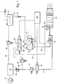
- 1 shows a first Embodiment of a schematically illustrated Mixture dispenser of urea for an exhaust system an internal combustion engine
- Figure 2 shows a second Embodiment of a schematically illustrated Mixture dispenser of urea for an exhaust system an internal combustion engine.
- a Reducing agent reservoir 1 is provided, which at a Commercial vehicle application a capacity of approx. 50 l for a urea-water solution.
- the Reducing agent reservoir 1 leads one Supply line 2 to one Reducing agent consumption container 3.
- the volume of the Reducing agent consumption container 3 only corresponds a fraction of the volume of the Reducing agent storage container 1.
- the mixture dispensing device also has a pump 11 on, the gas under a pressure of, for example, 7 bar in promotes a gas storage 12.
- a gas z. B. air Exhaust gas from the exhaust system of the internal combustion engine or an other gas.
- the gas storage 12 is also one Compressed gas line 13 connected in series adjustable throttle valve 16, a metering pressure control valve 17 and an electromagnetically actuated gas control valve 18 are arranged.
- the metering pressure control valve 17 controls the downstream pressure in the compressed gas line 13 for example to about 1 bar. That as a 2/2-way valve trained gas control valve 18 has a blocking position, in which it is shown in Figure 1, and a Open position.
- Urea pressure line 20 Urea pressure line 20 to a metering and Mixing device 21 which can be actuated electromagnetically and to which the compressed gas line 13 also leads.
- a metering and Mixing device 21 In the Dosing and mixing device 21 is a mixture of Urea-water solution supplied via the urea pressure line 20 with via the compressed gas line 13 supplied compressed gas.
- the dosage of Urea-water solution for example by means of a non injectors, for example one known from DE 34 11 537 A1 injection valve for the gasoline injection.
- a non injectors for example one known from DE 34 11 537 A1 injection valve for the gasoline injection.
- the dosed urea-water solution in a mixing room Compressed gas supplied to form a homogeneous mixture.
- the control of the gas control valve 18 and the metering and Mixing device 21 is carried out by an electronic Control unit 22. That by means of the compressed gas evenly and finely prepared mixture with the urea-water solution is in an exhaust system 23 by means of a provided thereon Atomizer device 25 upstream of a catalytic converter 26 known type blown.
- the atomizer device 25 is in the simplest form through a nozzle with a Blow-out opening is formed, but several can also be used Blow-out openings may be provided.
- the in the catalyst 26 The urea introduced by chemical reactions in Converts ammonia, which reduces nitrogen oxides in the Exhaust causes.
- a branch gas line 27 from that to an above the urea-water solution in the Reductant consumption container 3 formed gas space 30 leads and through which a connection from Reducing agent consumption container 3 to the compressed gas source can be produced by the pump 11 and the gas storage 12 is formed.
- the branch gas line 27 is one in series first pressure control valve 31 and downstream thereof Control valve 32 arranged.
- the first pressure control valve 31 regulates a gas pressure downstream in the branch gas line 27 of approx. 3 bar.
- the control valve 32 is in the present Embodiment designed as a 3/3-way valve and Electromagnetically confirmed by the electronic Control unit 22 can be controlled.
- first switching position 35th one in which this is a connection between the first Pressure control valve 31 and the Manufactures reducing agent consumption container 3 while it in a second switching position 36 the connection between the reducing agent consumption container 3 and the first Pressure control valve 31 interrupts and a connection from Gas space 30 of the reducing agent consumption container 3 to a relief line 37 that opens to the exhaust system 23 and thus leads to the atmosphere.
- this takes a third switching position 40 in which the connection from Reducing agent consumption container 3 for the first Pressure control valve 31 and thus to the gas pressure source 11, 12 and the connection to the relief line 37 is interrupted.
- a Fill level of the urea-water solution in the Reducing agent consumption container 3 measuring Level sensor 41 of a known type arranged, the for example works on a photo-optical basis and with the electronic control unit 22 is connected to at least then measurement signals to the electronic control unit 22nd forward when the minimum or maximum fill level the urea-water solution in the Reducing agent consumption container 3 is reached, so one Refill the urea-water solution in the Initiate or to reduce reducing agent consumption container interrupt.
- Level sensor 41 of a known type arranged, the for example works on a photo-optical basis and with the electronic control unit 22 is connected to at least then measurement signals to the electronic control unit 22nd forward when the minimum or maximum fill level the urea-water solution in the Reducing agent consumption container 3 is reached, so one Refill the urea-water solution in the Initiate or to reduce reducing agent consumption container interrupt.
- a connecting line 45 leads from gas storage 12 to Reductant reservoir 1.
- a second pressure control valve 46 is arranged, one Gas pressure of approx. 1.2 bar in the reducing agent reservoir 1 regulates.
- the mixture dispensing device according to the invention is required no feed pump for generating pressure for those in the Exhaust system 23 of the internal combustion engine to be blown Urea water solution. That in the first switch position 35 of the control valve 32 in the Reducing agent consumption container 3 introduced compressed gas causes a pressure build-up at the same height in the Urea water solution in Reducing agent consumption container 3, which is thus on the Urea pressure line 20 under this pressure of the metering and Mixing device 21 is fed. At the latest when in the reducing agent consumption container 3 by the Level sensor 41 reaching the minimum Level of the urea-water solution signals is, the electronic control unit 22 Control valve 32 in its second switching position 36 switched and thus the pressure in Reducing agent consumption container 3 almost to about Relieved atmospheric pressure.
- This refill the Reducing agent consumption container 3 can for example also be regulated so that the dosing and Mixing device 21 or when turning off the Internal combustion engine or at a start of the Internal combustion engine with the electronic control unit 22 a fill level of the urea-water solution below the maximum fill level, the control valve 32 in the described Controls to refill the Reducing agent consumption container 3 up to the maximum Level of the urea-water solution.
- a mixture dispenser according to the invention differs from the first embodiment Figure 1 only in that the control valve 32 as a 2/2-way valve with the first switch position 35 and the second Switch position 36 is formed, so no longer the blocking third switching position of the control valve 32 after Figure 1 has and instead of the check valve 5 in the Supply line 2, a refill valve 48 is provided.
- the refill valve 48 is Electromagnetically controlled by the electronic Control unit 22 and has a through position 49 in which it the supply line 2 from the reducing agent reservoir 1 to the reducing agent consumption container 3 opens while it assumes a blocking position 50 in the non-excited state.
- control valve 32 of the The embodiment of Figure 2 corresponds to Operation of the control valve 32 of the embodiment according to Figure 1.
- the refill valve 48 is then always the electronic control valve to the through position 49 switched when urea water solution from the Reducing agent reservoir 1 in the Reducing agent consumption container 3 are refilled should.
Abstract
Description
Die Erfindung geht aus von einer Gemischabgabevorrichtung nach der Gattung des Hauptanspruchs. Es besteht auch weiterhin die Forderung nach einer Verringerung schädlicher Abgasbestandteile von Brennkraftmaschinen. Zur Stickoxid-Reduktion in den Abgasen von Brennkraftmaschinen, insbesondere gemischverdichtenden selbstzündenden Brennkraftmaschinen, wird eine Harnstoff-Wasser-Lösung vor einen Katalysator in das Abgassystem der Brennkraftmaschine eingebracht. Im Katalysator wird der eingebrachte Harnstoff durch chemische Reaktionen in Ammoniak überführt, welcher die Reduktion von Stickoxiden bewirkt. Es ist schon eine Gemischabgabevorrichtung bekannt (EP 0 586 913 A2), bei der die Harnstoff-Wasser-Losung einem Reduktionsmittelvorratsbehälter entnommen und mittels einer Harnstofförderpumpe einem Mischraum zugeführt wird, in dem eine Vermischung mit einem Gas erfolgt, bevor dieses Gemisch mittels einer Zerstäuberdüse in das Abgassystem abgegeben wird. Da die Harnstoff-Wasser-Lösung keine Schmiereigenschaften besitzt, erreichen die derzeit verfügbaren Harnstofförderpumpen noch nicht die geforderten, störungsfreien Betriebszeiten.The invention is based on a mixture dispensing device according to the genus of the main claim. It also exists the demand for a harmful reduction continues Exhaust gas components from internal combustion engines. For nitrogen oxide reduction in the exhaust gases of internal combustion engines, especially self-igniting mixture-compressing Internal combustion engines, a urea-water solution is provided a catalyst in the exhaust system of the internal combustion engine brought in. The urea introduced is in the catalyst converted into ammonia by chemical reactions, which the reduction of nitrogen oxides. It's already one Mixture dispenser known (EP 0 586 913 A2), in which the urea-water solution Reductant reservoir removed and using a Urea feed pump is fed to a mixing room in which mixing with a gas occurs before this mixture dispensed into the exhaust system by means of an atomizing nozzle becomes. Because the urea-water solution is none Has lubricating properties, currently achieve available urea feed pumps have not yet met the required trouble-free operating times.
Die Gemischabgabevorrichtung mit den kennzeichnenden Merkmalen des Hauptanspruchs hat demgegenüber den Vorteil, daß auf einfache Art und Weise auf die Verwendung einer Harnstofförderpumpe verzichtet werden kann und auch bei Bedarf großer Mengen von Harnstoff-Wasser-Lösung immer ein ausreichender Vorrat zur Verfügung steht, wobei lediglich für einen kleineren, die Harnstoff-Wasser-Lösung aufnehmenden Verbrauchsbehälter die Richtlinien der Druckbehälterverordnung eingehalten werden müssen. Dieser Verbrauchsbehälter ist in Pausen sehr schnell wieder aus dem Vorratsbehälter mit der Harnstoff-Wasser-Lösung nachfüllbar und mit dem erforderlichen Gasdruck beaufschlagbar.The mixture dispenser with the characteristic In contrast, features of the main claim have the advantage that in a simple way on the use of a Urea feed pump can be dispensed with and also at Always need large amounts of urea water solution sufficient stock is available, although only for a smaller one, the urea-water solution receptacle Pressure vessel regulation must be observed. This The consumption container is quickly removed from the break Refillable with the urea-water solution and can be supplied with the required gas pressure.
Durch die in den Unteransprüchen aufgeführten Maßnahmen sind vorteilhafte Weiterbildungen und Verbesserungen der im Hauptanspruch angegebenen Gemischabgabevorrichtung möglich.By the measures listed in the subclaims advantageous developments and improvements in Main claim specified mixture dispenser possible.
Besonders vorteilhaft ist es, eine Druckgasquelle über ein erstes Druckregelventil mit dem Reduktionsmittelverbrauchsbehälter zu verbinden und über ein zweites Druckregelventil mit dem Reduktionsmittelvorratsbehälter, wobei der vom ersten Druckregelventil geregelte Gasdruck größer als der vom zweiten Druckregelventil geregelte Gasdruck ist. Dadurch steht für die Abgabe der Harnstoff-Wasser-Lösung in das Abgassystem ein ausreichend großer Druck zur Verfügung, während das Nachfüllen des Verbrauchsbehälters bei einem geringeren Druckniveau erfolgt, so daß dabei die Richtlinien der Druckbehälterverordnung nicht beachtet werden müssen.It is particularly advantageous to use a compressed gas source first pressure control valve with the Connect reducing agent consumption container and via a second pressure control valve with the Reductant reservoir, the one from the first Pressure control valve controlled gas pressure greater than that of second pressure control valve is regulated gas pressure. Thereby stands for the release of the urea-water solution into the Exhaust system a sufficiently large pressure is available while refilling the consumable at one lower pressure level, so doing the guidelines the pressure vessel regulation do not have to be observed.
Ebenfalls vorteilhaft ist es, daß zwischen dem ersten Druckregelventil und dem Reduktionsmittelverbrauchsbehälter ein Steuerventil vorgesehen ist, das in einer ersten Schaltstellung eine Verbindung vom Reduktionsmittelverbrauchsbehälter zum ersten Druckregelventil herstellt und in einer zweiten Schaltstellung die Verbindung zum ersten Druckregelventil unterbricht und eine Verbindung von einem Gasraum des Reduktionsmittelverbrauchsbehälters zur Atmosphäre öffnet. Hierdurch läßt sich auf einfache Art und Weise eine schnelle Druckbeaufschlagung der Harnstoff-Wasser-Lösung im Reduktionsmittelverbrauchsbehälter sowie ein schneller Druckabbau erreichen.It is also advantageous that between the first Pressure control valve and the reducing agent consumption container a control valve is provided in a first Switch position a connection from Reducing agent consumption container for the first Manufactures pressure control valve and in a second Switch position the connection to the first pressure control valve interrupts and connects a gas space of the Reducing agent consumption container opens to the atmosphere. This allows a quick and easy way Pressurization of the urea-water solution in the Reducing agent consumption container as well as a faster Achieve pressure reduction.
Weiterhin vorteilhaft ist es, zwischen dem Reduktionsmittelvorratsbehälter und dem Reduktionsmittelverbrauchsbehälter ein in Richtung zum Reduktionsmittelverbrauchsbehälter öffnendes Rückschlagventil anzuordnen oder stattdessen ein Nachfüllventil, das in einer ersten Schaltstellung die Verbindung zwischen dem Reduktionsmittelvorratsbehälter und dem Reduktionsmittelverbrauchsbehälter unterbricht und in einer zweiten Schaltstellung zum Nachfüllen des Reduktionsmittelverbrauchsbehälters diese Verbindung öffnet. Dadurch ist sichergestellt, daß vom Reduktionsmittelvorratsbehälter eine schnelle Befüllung des Reduktionsmittelverbrauchsbehälters erfolgen kann, aber eine Rückströmung vom Reduktionsmittelverbrauchsbehälter zum Reduktionsmittelvorratsbehälter verhindert wird.It is also advantageous between the Reductant reservoir and the Reducing agent consumption container one towards Reducing agent consumption container opening Check valve to arrange or instead Refill valve that in a first switch position Connection between the reducing agent reservoir and interrupts the reducing agent consumption container and in a second switch position for refilling the Reducing agent consumption container opens this connection. This ensures that from Reductant reservoir a quick filling of the Reducing agent consumption container can be made, but a Return flow from the reducing agent consumption container to Reductant reservoir is prevented.
Im oder am Reduktionsmittelverbrauchsbehälter ist in vorteilhafter Weise ein die Füllhöhe der Harnstoff-Wasser-Lösung messender Füllstandsensor angeordnet, der bei Erreichen der maximal zulässigen Füllhohe eine weitere Befüllung unterbricht und spätestens bei Erreichen einer bestimmten minimalen Füllhöhe ein Nachfüllen des Reduktionsmittelverbrauchsbehälters einleitet.In or on the reducing agent consumption container is in advantageously the level of the urea-water solution measuring level sensor arranged at Another maximum is reached Filling interrupts and at the latest when one is reached certain minimum filling level a refill of the Initiates reducing agent consumption container.
In ebenfalls vorteilhafter Weise ist in dem Reduktionsmittelverbrauchsbehälter ein Heizelement angeordnet, das bei zu tiefen Temperaturen ein Gefrieren der Harnstoff-Wasser-Lösung verhindert oder ein Auftauen bewirkt.It is also advantageous in that Reducing agent consumption container a heating element arranged, which freezes at too low temperatures Prevents urea-water solution or thawing causes.
Ausführungsbeispiele der Erfindung sind in der Zeichnung vereinfacht dargestellt und in der nachfolgenden Beschreibung naher erläutert. Es zeigen Figur 1 ein erstes Ausführungsbeispiel einer schematisch dargestellten Gemischabgabevorrichtung von Harnstoff für ein Abgassystem einer Brennkraftmaschine, Figur 2 ein zweites Ausführungsbeispiel einer schematisch dargestellten Gemischabgabevorrichtung von Harnstoff für ein Abgassystem einer Brennkraftmaschine.Embodiments of the invention are in the drawing shown in simplified form and in the following Description explained in more detail. 1 shows a first Embodiment of a schematically illustrated Mixture dispenser of urea for an exhaust system an internal combustion engine, Figure 2 shows a second Embodiment of a schematically illustrated Mixture dispenser of urea for an exhaust system an internal combustion engine.
Bei der Gemischabgabevorrichtung zur Abgabe einer Harnstoff-Wasser-Lösung
vor einen Katalysator im Abgassystem einer
Brennkraftmaschine, insbesondere einer gemischverdichtenden
selbstzündenden Brennkraftmaschine, nach der Figur 1 ist ein
Reduktionsmittelvorratsbehälter 1 vorgesehen, der bei einer
Nutzkraftfahrzeug-Anwendung ein Fassungsvermögen von ca.
50 l für eine Harnstoff-Wasser-Lösung hat. Von dem
Reduktionsmittelvorratsbehälter 1 führt eine
Versorgungsleitung 2 zu einem
Reduktionsmittelverbrauchsbehalter 3. Das Volumen des
Reduktionsmittelverbrauchsbehälters 3 entspricht lediglich
einem Bruchteil des Volumens des
Reduktionsmittelvorratsbehälters 1. So beträgt das
Fassungsvermögen des Reduktionsmittelverbrauchsbehälters 3
bei einer Nutzkraftfahrzeug-Anwendung ca. 1 l, was etwa der
Menge an Harnstoff-Wasser-Lösung entspricht, die etwa an
einem Tag zur Reduzierung der Stickoxid-Emissionen im Abgas
erforderlich ist. Damit ergibt sich ein klein und kompakt
ausgestalteter Reduktionsmittelverbrauchsbehälter 3. In der
die Verbindung zwischen dem Reduktionsmittelvorratsbehälter
1 und dem Reduktionsmittelverbrauchsbehalter 3 herstellenden
Versorgungsleitung 2 ist ein Rückschlagventil 5 angeordnet,
das in Richtung zum Reduktionsmittelverbrauchsbehälter 3
öffnet. Mit einem Gasraum 6 oberhalb der Harnstoff-Wasser-Losung
im Reduktionsmittelvorratsbehalter 1 ist ein in
Richtung zur Atmosphäre hin öffnendes Druckbegrenzungsventil
7 verbunden, das bei einem Druck von ca. 1,3 bar öffnet, so
daß der Reduktionsmittelvorratsbehälter 1 nicht nach den
Richtlinien der Druckbehälterverordnung ausgelegt werden
muß.In the mixture dispenser for dispensing a urea-water solution
in front of a catalyst in the exhaust system
Internal combustion engine, especially a mixture compressing
Self-igniting internal combustion engine, according to Figure 1 is a
Reducing agent reservoir 1 is provided, which at a
Commercial vehicle application a capacity of approx.
50 l for a urea-water solution. Of the
Reducing agent reservoir 1 leads one
Die Gemischabgabevorrichtung weist weiterhin eine Pumpe 11
auf, die Gas unter einem Druck mit beispielsweise 7 bar in
einen Gasspeicher 12 fördert. Als Gas dient z. B. Luft,
Abgas aus dem Abgassystem der Brennkraftmaschine oder ein
anderes Gas. Mit dem Gasspeicher 12 ist ebenfalls eine
Druckgasleitung 13 verbunden, in der in Reihe ein
verstellbares Drosselventil 16, ein Dosierdruckregelventil
17 und ein elektromagnetisch betätigbares Gassteuerventil 18
angeordnet sind. Das Dosierdruckregelventil 17 regelt den
stromabwärtigen Druck in der Druckgasleitung 13
beispielsweise auf ca. 1 bar. Das als 2/2-Wegeventil
ausgebildete Gassteuerventil 18 hat eine Sperrstellung, in
der es in Figur 1 dargestellt ist, und eine
Durchlaßstellung.The mixture dispensing device also has a
Von dem Reduktionsmittelverbrauchsbehälter 3 führt eine
Harnstoffdruckleitung 20 zu einer Dosier- und
Mischeinrichtung 21, die elektromagnetisch betätigbar ist
und zu der ebenfalls die Druckgasleitung 13 führt. In der
Dosier- und Mischeinrichtung 21 erfolgt eine Mischung der
über die Harnstoffdruckleitung 20 zugeführten Harnstoff-Wasser-Lösung
mit dem über die Druckgasleitung 13
zugeführten Druckgas. Dabei erfolgt die Dosierung der
Harnstoff-Wasser-Lösung beispielsweise mittels eines nicht
näher dargestellten Einspritzventiles, beispielsweise eines
durch die DE 34 11 537 A1 bekannten Einspritzventiles für
die Benzineinspritzung. Wie beispielsweise in der
EP 0 586 913 A2 beschrieben und dargestellt ist, wird der
dosierten Harnstoff-Wasser-Lösung in einem Mischraum das
Druckgas zur Bildung eines homogenen Gemisches zugeführt.
Die Ansteuerung des Gassteuerventils 18 und der Dosier- und
Mischeinrichtung 21 erfolgt durch ein elektronisches
Steuergerät 22. Das mittels des Druckgases gleichmäßig und
fein aufbereitete Gemisch mit der Harnstoff-Wasser-Lösung
wird in ein Abgassystem 23 mittels einer daran vorgesehenen
Zerstäubereinrichtung 25 stromaufwärts eines Katalysators 26
bekannter Bauart eingeblasen. Die Zerstäubereinrichtung 25
wird dabei in einfachster Form durch eine Düse mit einer
Ausblaseöffnung gebildet, es können jedoch auch mehrere
Ausblaseöffnungen vorgesehen sein. Der in den Katalysator 26
eingebrachte Harnstoff wird durch chemische Reaktionen in
Ammoniak überführt, welcher die Reduktion der Stickoxide im
Abgas bewirkt.One leads from the reducing
Von der Druckgasleitung 13 zweigt zwischen dem Drosselventil
16 und dem Dosierdruckregelventil 17 eine Zweiggasleitung 27
ab, die zu einem oberhalb der Harnstoff-Wasser-Lösung im
Reduktionsmittelverbrauchsbehälter 3 gebildeten Gasraum 30
führt und über die eine Verbindung vom
Reduktionsmittelverbrauchsbehälter 3 zu der Druckgasquelle
herstellbar ist, die durch die Pumpe 11 und den Gasspeicher
12 gebildet wird. In der Zweiggasleitung 27 ist in Reihe ein
erstes Druckregelventil 31 und stromabwärts davon ein
Steuerventil 32 angeordnet. Das erste Druckregelventil 31
regelt stromabwärts in der Zweiggasleitung 27 einen Gasdruck
von ca. 3 bar. Das Steuerventil 32 ist bei dem vorliegenden
Ausführungsbeispiel als 3/3-Wegeventil ausgebildet und
elektromagnetisch bestätigtdurch das elektronische
Steuergerät 22 ansteuerbar. Im erregten Zustand des
Steuerventiles 39 nimmt dieses eine erste Schaltstellung 35
ein, in der dieses eine Verbindung zwischen dem ersten
Druckregelventil 31 und dem
Reduktionsmittelverbrauchsbehälter 3 herstellt, wahrend es
in einer zweiten Schaltstellung 36 die Verbindung zwischen
dem Reduktionsmittelverbrauchsbehälter 3 und dem ersten
Druckregelventil 31 unterbricht und eine Verbindung vom
Gasraum 30 des Reduktionsmittelverbrauchsbehälters 3 zu
einer Entlastungsleitung 37 öffnet, die zum Abgassystem 23
und damit zur Atmosphäre führt. Im nicht erregten Zustand
des Steuerventils 32 nimmt dieses eine dritte Schaltstellung
40 ein, in der die Verbindung vom
Reduktionsmittelverbrauchsbehälter 3 zum ersten
Druckregelventil 31 und damit zur Gasdruckquelle 11, 12 und
die Verbindung zur Entlastungsleitung 37 unterbrochen wird.From the
Im oder am Reduktionsmittelverbrauchsbehälter 3 ist ein die
Füllhöhe der Harnstoff-Wasser-Lösung im
Reduktionsmittelverbrauchsbehälter 3 messender
Füllstandssensor 41 bekannter Bauart angeordnet, der
beispielsweise auf photooptischer Basis arbeitet und mit dem
elektronischen Steuergerät 22 verbunden ist, um wenigstens
dann Meßsignale an das elektronische Steuergerät 22
weiterzuleiten, wenn die minimale oder die maximale Füllhöhe
der Harnstoff-Wasser-Lösung im
Reduktionsmittelverbrauchsbehälter 3 erreicht ist, um so ein
Nachfüllen der Harnstoff-Wasser-Lösung in den
Reduktionsmittelverbrauchsbehälter einzuleiten oder zu
unterbrechen. Um einen zuverlässigen Betrieb der
Gemischabgabevorrichtung auch bei niederen Temperaturen,
z. B. im Winterbetrieb zu gewahrleisten, ist im
Reduktionsmittelverbrauchsbehälter 3 ein durch das
elektronische Steuergerät 22 angesteuertes elektrisches
Heizelement 42 angeordnet, das ein Gefrieren bei niederen
Temperaturen, beispielsweise unterhalb -10°C, verhindert.
Eine Verbindungsleitung 45 führt vom Gasspeicher 12 zum
Reduktionsmittelvorratsbehälter 1. In der Verbindungsleitung
45 ist ein zweites Druckregelventil 46 angeordnet, das einen
Gasdruck von ca. 1,2 bar im Reduktionsmittelvorratsbehälter
1 regelt.In or on the reducing
Die erfindungsgemäße Gemischabgabevorrichtung benötigt
keinerlei Förderpumpe zur Druckerzeugung für die in das
Abgassystem 23 der Brennkraftmaschine einzublasende
Harnstoff-Wasser-Lösung. Das in der ersten Schaltstellung 35
des Steuerventils 32 in den
Reduktionsmittelverbrauchsbehälter 3 eingeleitete Druckgas
bewirkt einen Druckaufbau in der gleichen Hohe in der
Harnstoff-Wasser-Lösung im
Reduktionsmittelverbrauchsbehälter 3, die somit über die
Harnstoffdruckleitung 20 unter diesem Druck der Dosier- und
Mischeinrichtung 21 zugeleitet wird. Spätestens dann, wenn
in dem Reduktionsmittelverbrauchsbehälter 3 durch den
Füllstandsensor 41 das Erreichen der minimalen
Füllstandshohe der Harnstoff-Wasser-Lösung signalisiert
wird, wird durch das elektronische Steuergerät 22 das
Steuerventil 32 in seine zweite Schaltstellung 36
umgeschaltet und damit der Druck im
Reduktionsmittelverbrauchsbehälter 3 nahezu auf etwa
Atmosphärendruck entlastet. Da in dem
Reduktionsmittelvorratsbehälter 1 ein über dem
Atmosphärendruck liegender Druck von ca. 1,2 bar herrscht,
öffnet das Rückschlagventil 5 in der Versorgungsleitung 2
und Harnstoff-Wasser-Lösung strömt über die
Versorgungsleitung 2 in den
Reduktionsmittelverbrauchsbehälter 3, bis der
Füllstandsensor 41 die maximal zulässige Füllmenge von
Harnstoff-Wasser-Lösung dem elektronischen Steuergerät 22
signalisiert, das daraufhin das Steuerventil 32 ansteuert,
so daß das Steuerventil entweder seine sperrende dritte
Schaltstellung 40 einnimmt oder seine erste Schaltstellung
35, so daß durch den erneuten Druckaufbau im
Reduktionsmittelverbrauchsbehälter 3 das Rückschlagventil 5
geschlossen wird. Dieser Nachfüllvorgang des
Reduktionsmittelverbrauchsbehälters 3 kann beispielsweise
auch so geregelt sein, daß in Dosierpausen der Dosier- und
Mischeinrichtung 21 oder beim Abstellen der
Brennkraftmaschine oder bei einem Start der
Brennkraftmaschine das elektronische Steuergerät 22 bei
einer Füllhöhe der Harnstoff-Wasser-Lösung unterhalb der
maximalen Füllhöhe das Steuerventil 32 in der geschilderten
Weise ansteuert, um ein Nachfüllen des
Reduktionsmittelverbrauchsbehälters 3 bis zur maximalen
Füllhöhe der Harnstoff-Wasser-Lösung durchzuführen.The mixture dispensing device according to the invention is required
no feed pump for generating pressure for those in the
Das in der Figur 2 dargestellte zweite Ausführungsbeispiel
einer erfindungsgemäßen Gemischabgabevorrichtung
unterscheidet sich von dem ersten Ausführungsbeispiel nach
Figur 1 lediglich dadurch, daß das Steuerventil 32 als 2/2-Wegeventil
mit der ersten Schaltstellung 35 und der zweiten
Schaltstellung 36 ausgebildet ist, also nicht mehr die
sperrende dritte Schaltstellung des Steuerventils 32 nach
Figur 1 aufweist und anstelle des Rückschlagventils 5 in der
Versorgungsleitung 2 ein Nachfüllventil 48 vorgesehen ist.
Die gegenüber dem Ausführungsbeispiel nach Figur 1
gleichbleibenden und gleichwirkenden Teile sind bei dem
Ausführungsbeispiel nach Figur 2 durch die gleichen
Bezugszeichen gekennzeichnet. Das Nachfüllventil 48 ist
elektromagnetisch ansteuerbar durch das elektronische
Steuergerät 22 und hat eine Durchgangsstellung 49, in der es
die Versorgungsleitung 2 vom Reduktionsmittelvorratsbehälter
1 zum Reduktionsmittelverbrauchsbehälter 3 öffnet, wahrend
es im nicht erregten Zustand eine Sperrstellung 50 einnimmt. The second embodiment shown in Figure 2
a mixture dispenser according to the invention
differs from the first embodiment
Figure 1 only in that the
Die Wirkungsweise des Steuerventils 32 des
Ausführungsbeispieles nach Figur 2 entspricht der
Wirkungsweise des Steuerventils 32 des Ausführungsbeispieles
nach Figur 1. Das Nachfüllventil 48 wird immer dann durch
das elektronische Steuerventil in die Durchgangsstellung 49
geschaltet, wenn Harnstoff-Wasser-Lösung aus dem
Reduktionsmittelvorratsbehälter 1 in den
Reduktionsmittelverbrauchsbehälter 3 nachgefüllt werden
soll.The operation of the
Claims (10)
Applications Claiming Priority (2)
| Application Number | Priority Date | Filing Date | Title |
|---|---|---|---|
| DE19800421A DE19800421A1 (en) | 1998-01-08 | 1998-01-08 | Mixture dispenser |
| DE19800421 | 1998-01-08 |
Publications (3)
| Publication Number | Publication Date |
|---|---|
| EP0928884A2 true EP0928884A2 (en) | 1999-07-14 |
| EP0928884A3 EP0928884A3 (en) | 2003-01-02 |
| EP0928884B1 EP0928884B1 (en) | 2006-09-27 |
Family
ID=7854149
Family Applications (1)
| Application Number | Title | Priority Date | Filing Date |
|---|---|---|---|
| EP98118527A Expired - Lifetime EP0928884B1 (en) | 1998-01-08 | 1998-09-30 | Mixture delivery device |
Country Status (2)
| Country | Link |
|---|---|
| EP (1) | EP0928884B1 (en) |
| DE (2) | DE19800421A1 (en) |
Cited By (29)
| Publication number | Priority date | Publication date | Assignee | Title |
|---|---|---|---|---|
| WO2001038703A1 (en) * | 1999-11-24 | 2001-05-31 | Siemens Aktiengesellschaft | Device and method for the nitrogen oxide control of waste gas in an internal combustion engine |
| WO2002057603A1 (en) * | 2001-01-19 | 2002-07-25 | Robert Bosch Gmbh | Device for metering a urea solution devoid of enzymes, comprising a sensor unit for controlling physical condition variables of said urea solution |
| WO2005045209A1 (en) * | 2003-11-04 | 2005-05-19 | Robert Bosch Gmbh | Device for introducing a reducing agent into the exhaust gas of an internal combustion engine |
| EP1612381A1 (en) | 2004-06-30 | 2006-01-04 | Iveco S.p.A. | System and method for injecting a liquid into a gas stream, exhaust gas treatment device and vehicle incorporating said device |
| WO2007017080A1 (en) * | 2005-08-06 | 2007-02-15 | Eichenauer Heizelemente Gmbh & Co. Kg | Heating system |
| DE102006061732A1 (en) | 2006-12-28 | 2008-07-03 | Robert Bosch Gmbh | Liquid reducing agent dosage device for reduction of nitrogen oxides in exhaust gas, has storage container connected with work container, and storage pump for pumping liquid reducing agent from storage container to work container |
| DE102006061734A1 (en) | 2006-12-28 | 2008-07-03 | Robert Bosch Gmbh | Liquid reducing agent e.g. aqueous urea solution, dosing device for e.g. diesel-operated internal combustion engine, of motor vehicle, has dosing line connected with operating container, which is connected with storage container |
| WO2008092612A1 (en) | 2007-02-01 | 2008-08-07 | Bayerische Motoren Werke Aktiengesellschaft | Feed device for a liquid additive for an internal combustion engine |
| WO2008092613A1 (en) | 2007-02-01 | 2008-08-07 | Bayerische Motoren Werke Aktiengesellschaft | Device for feeding a liquid additive into an internal combustion engine |
| WO2009045325A1 (en) * | 2007-09-28 | 2009-04-09 | Caterpillar Inc. | Exhaust after-treatment system having a secondary tank |
| WO2009090101A1 (en) * | 2008-01-17 | 2009-07-23 | Inergy Automotive Systems Research (Societe Anonyme) | Process for transferring a liquid using a pump |
| US7594393B2 (en) | 2004-09-07 | 2009-09-29 | Robert Bosch Gmbh | Apparatus for introducing a reducing agent into the exhaust of an internal combustion engine |
| WO2009121649A1 (en) * | 2008-04-02 | 2009-10-08 | Robert Bosch Gmbh | Scr system comprising a plurality of tanks |
| DE102008000932A1 (en) | 2008-04-02 | 2009-10-08 | Robert Bosch Gmbh | Device for dosing a liquid reducing agent |
| WO2009156204A1 (en) * | 2008-06-24 | 2009-12-30 | Robert Bosch Gmbh | Exhaust gas after-treatment device for an internal combustion engine |
| WO2010009790A1 (en) | 2008-07-23 | 2010-01-28 | Bayerische Motoren Werke Aktiengesellschaft | Reducing agent tank for providing reducing agent to an exhaust gas system having a check valve |
| DE102008041903A1 (en) | 2008-09-09 | 2010-03-11 | Robert Bosch Gmbh | Exhaust gas post-treatment method for diesel engine of motor vehicle, involves providing auxiliary fluid in auxiliary agent, and supplying fuel to internal-combustion engine from fuel tank that is exclusively refueled with fuel |
| DE102008041805A1 (en) | 2008-09-04 | 2010-03-11 | Robert Bosch Gmbh | Tank arrangement for supplying aqueous urea solution used for selective catalytic reduction of nitrogen oxide from exhaust gas of internal combustion engine of vehicle, has chamber wall protruding from cover into inner side of container |
| CN101975102A (en) * | 2010-10-20 | 2011-02-16 | 中国第一汽车集团公司 | Pneumatic single-urea box full-deflating emptying pipeline SCR urea system |
| CN101975103A (en) * | 2010-10-20 | 2011-02-16 | 中国第一汽车集团公司 | Electronic-control urea pump water heating SCR urea system of pneumatic double urea box |
| CN101979131A (en) * | 2010-10-20 | 2011-02-23 | 中国第一汽车集团公司 | Pneumatic dual-urea tank urea one-way valve control water heating silicon controlled rectifier (SCR) urea system |
| WO2011135043A1 (en) * | 2010-04-30 | 2011-11-03 | Inergy Automotive Systems Research S.A. | Process for transferring a liquid using a pump |
| WO2012031810A1 (en) * | 2010-09-09 | 2012-03-15 | Robert Bosch Gmbh | Exhaust-gas aftertreatment system and method for dosing a medium into the exhaust tract of an internal combustion engine |
| CN102388208A (en) * | 2009-04-16 | 2012-03-21 | 因勒纪汽车系统研究公司 | System and process for storing an additive and injecting it into the exhaust gases of an engine |
| CN102451617A (en) * | 2010-10-20 | 2012-05-16 | 中国第一汽车集团公司 | Pneumatic double urea tank electronically-controlled urea loading pump built-in filter SCR (silicon controlled rectifier) urea system |
| DE102011081580A1 (en) | 2011-03-04 | 2012-09-06 | Robert Bosch Gmbh | Exhaust after-treatment system of an internal combustion engine and method for dosing a liquid in the exhaust passage of the internal combustion engine |
| EP3032059A1 (en) * | 2014-12-09 | 2016-06-15 | Delphi International Operations Luxembourg S.à r.l. | Scr dosing system |
| EP3156621A1 (en) * | 2015-10-13 | 2017-04-19 | Clark Equipment Company | Remote fluid supply for an engine |
| DE102007005005B4 (en) | 2007-02-01 | 2022-06-30 | Bayerische Motoren Werke Aktiengesellschaft | Device for an internal combustion engine for supplying a liquid additive |
Families Citing this family (5)
| Publication number | Priority date | Publication date | Assignee | Title |
|---|---|---|---|---|
| DE19952428A1 (en) * | 1999-10-30 | 2001-05-03 | Man Nutzfahrzeuge Ag | Method and device for the combined catalytic NOx reduction and sound attenuation of exhaust gas in the exhaust line of an internal combustion engine |
| DE20119514U1 (en) | 2001-12-03 | 2002-02-28 | Purem Abgassysteme Gmbh & Co | Reduktionsmitteldosiereinrichtung |
| US7836684B2 (en) | 2005-06-04 | 2010-11-23 | Eichenauer Heizelemente Gmbh & Co. Kg | Urea supply system for a waste gas cleaning catalyst and heating insert suitable therefor |
| DE102007035938A1 (en) | 2007-07-31 | 2009-02-05 | Eberspächer Unna GmbH & Co. KG | Reducing agent dosing system for internal-combustion engine, has injector for delivering reducing agent into exhaust gas pipeline, where pre-conveying units exhibit reducing agent feed pumps for conveying reducing agent |
| DE102008034213A1 (en) * | 2008-07-23 | 2010-01-28 | Bayerische Motoren Werke Aktiengesellschaft | Reducing agent- tank i.e. multi-container system, for supplying e.g. aqueous urea solution, to exhaust gas system in vehicle, has measuring device to determine filling conditions of one of containers, before decanting device is enabled |
Citations (2)
| Publication number | Priority date | Publication date | Assignee | Title |
|---|---|---|---|---|
| DE3411537A1 (en) | 1984-03-29 | 1985-10-10 | Robert Bosch Gmbh, 7000 Stuttgart | Electromagnetically operatable fuel injection valve |
| EP0586913A2 (en) | 1992-09-08 | 1994-03-16 | MAN Nutzfahrzeuge Aktiengesellschaft | Spray apparatus |
Family Cites Families (3)
| Publication number | Priority date | Publication date | Assignee | Title |
|---|---|---|---|---|
| DE3835939C2 (en) * | 1987-10-31 | 1998-01-15 | Volkswagen Ag | Exhaust system |
| DE9308772U1 (en) * | 1993-06-12 | 1993-09-30 | Schneider Arno Dipl Ing | Device for operating a combustion system, in particular in the form of a cogeneration or a combined heat and power plant with an exhaust gas cleaning system, in particular for the combustion of heavy heating oil or heavy oil |
| DE59507350D1 (en) * | 1994-09-13 | 2000-01-05 | Siemens Ag | METHOD AND DEVICE FOR INPUTING LIQUID IN AN EXHAUST GAS PURIFICATION DEVICE |
-
1998
- 1998-01-08 DE DE19800421A patent/DE19800421A1/en not_active Withdrawn
- 1998-09-30 EP EP98118527A patent/EP0928884B1/en not_active Expired - Lifetime
- 1998-09-30 DE DE59813743T patent/DE59813743D1/en not_active Expired - Lifetime
Patent Citations (2)
| Publication number | Priority date | Publication date | Assignee | Title |
|---|---|---|---|---|
| DE3411537A1 (en) | 1984-03-29 | 1985-10-10 | Robert Bosch Gmbh, 7000 Stuttgart | Electromagnetically operatable fuel injection valve |
| EP0586913A2 (en) | 1992-09-08 | 1994-03-16 | MAN Nutzfahrzeuge Aktiengesellschaft | Spray apparatus |
Cited By (52)
| Publication number | Priority date | Publication date | Assignee | Title |
|---|---|---|---|---|
| US6637196B1 (en) | 1999-11-24 | 2003-10-28 | Siemens Aktiengesellschaft | Device and method for denoxing exhaust gas from an internal combustion engine |
| WO2001038703A1 (en) * | 1999-11-24 | 2001-05-31 | Siemens Aktiengesellschaft | Device and method for the nitrogen oxide control of waste gas in an internal combustion engine |
| WO2002057603A1 (en) * | 2001-01-19 | 2002-07-25 | Robert Bosch Gmbh | Device for metering a urea solution devoid of enzymes, comprising a sensor unit for controlling physical condition variables of said urea solution |
| WO2005045209A1 (en) * | 2003-11-04 | 2005-05-19 | Robert Bosch Gmbh | Device for introducing a reducing agent into the exhaust gas of an internal combustion engine |
| EP1612381A1 (en) | 2004-06-30 | 2006-01-04 | Iveco S.p.A. | System and method for injecting a liquid into a gas stream, exhaust gas treatment device and vehicle incorporating said device |
| US7594393B2 (en) | 2004-09-07 | 2009-09-29 | Robert Bosch Gmbh | Apparatus for introducing a reducing agent into the exhaust of an internal combustion engine |
| CN101238275B (en) * | 2005-08-06 | 2011-07-20 | 宏牛加热元件有限及两合公司 | Heating system |
| WO2007017080A1 (en) * | 2005-08-06 | 2007-02-15 | Eichenauer Heizelemente Gmbh & Co. Kg | Heating system |
| US8680437B2 (en) | 2005-08-06 | 2014-03-25 | Eichenauer Heizelemente Gmbh & Co. Kg | Heating system |
| DE102006061732A1 (en) | 2006-12-28 | 2008-07-03 | Robert Bosch Gmbh | Liquid reducing agent dosage device for reduction of nitrogen oxides in exhaust gas, has storage container connected with work container, and storage pump for pumping liquid reducing agent from storage container to work container |
| WO2008080691A1 (en) * | 2006-12-28 | 2008-07-10 | Robert Bosch Gmbh | Device for metering a liquid reducing agent |
| WO2008080689A1 (en) * | 2006-12-28 | 2008-07-10 | Robert Bosch Gmbh | Device for metering a reducing agent |
| DE102006061734A1 (en) | 2006-12-28 | 2008-07-03 | Robert Bosch Gmbh | Liquid reducing agent e.g. aqueous urea solution, dosing device for e.g. diesel-operated internal combustion engine, of motor vehicle, has dosing line connected with operating container, which is connected with storage container |
| US9494069B2 (en) | 2006-12-28 | 2016-11-15 | Robert Bosch Gmbh | Device for metering a liquid reducing agent |
| US8459300B2 (en) | 2007-02-01 | 2013-06-11 | Bayerische Motoren Werke Aktiengesellschaft | Arrangement for feeding a liquid additive for an internal-combustion engine |
| US8201577B2 (en) | 2007-02-01 | 2012-06-19 | Bayerische Motoren Werke Aktiengesellschaft | Feeding arrangement for a liquid additive for an internal-combustion-engine |
| WO2008092613A1 (en) | 2007-02-01 | 2008-08-07 | Bayerische Motoren Werke Aktiengesellschaft | Device for feeding a liquid additive into an internal combustion engine |
| DE102007005005B4 (en) | 2007-02-01 | 2022-06-30 | Bayerische Motoren Werke Aktiengesellschaft | Device for an internal combustion engine for supplying a liquid additive |
| WO2008092612A1 (en) | 2007-02-01 | 2008-08-07 | Bayerische Motoren Werke Aktiengesellschaft | Feed device for a liquid additive for an internal combustion engine |
| WO2009045325A1 (en) * | 2007-09-28 | 2009-04-09 | Caterpillar Inc. | Exhaust after-treatment system having a secondary tank |
| US8096112B2 (en) | 2007-09-28 | 2012-01-17 | Caterpillar Inc. | Exhaust after-treatment system having a secondary tank |
| FR2926542A1 (en) * | 2008-01-17 | 2009-07-24 | Inergy Automotive Systems Res | PROCESS FOR THE TRANSFER OF A LIQUID USING A PUMP |
| CN101939516B (en) * | 2008-01-17 | 2013-05-08 | 因勒纪汽车系统研究公司 | Process for transferring a liquid using a pump |
| WO2009090101A1 (en) * | 2008-01-17 | 2009-07-23 | Inergy Automotive Systems Research (Societe Anonyme) | Process for transferring a liquid using a pump |
| US8615986B2 (en) | 2008-01-17 | 2013-12-31 | Inergy Automotive Systems Research (Societe Anonyme) | Process for transferring a liquid using a pump |
| WO2009121649A1 (en) * | 2008-04-02 | 2009-10-08 | Robert Bosch Gmbh | Scr system comprising a plurality of tanks |
| WO2009121644A1 (en) * | 2008-04-02 | 2009-10-08 | Robert Bosch Gmbh | Device for dosing a liquid reducing agent |
| DE102008000932A1 (en) | 2008-04-02 | 2009-10-08 | Robert Bosch Gmbh | Device for dosing a liquid reducing agent |
| US9574478B2 (en) | 2008-06-24 | 2017-02-21 | Robert Bosch Gmbh | Exhaust gas posttreatment device for an internal combustion engine |
| WO2009156204A1 (en) * | 2008-06-24 | 2009-12-30 | Robert Bosch Gmbh | Exhaust gas after-treatment device for an internal combustion engine |
| WO2010009790A1 (en) | 2008-07-23 | 2010-01-28 | Bayerische Motoren Werke Aktiengesellschaft | Reducing agent tank for providing reducing agent to an exhaust gas system having a check valve |
| DE102008041805A1 (en) | 2008-09-04 | 2010-03-11 | Robert Bosch Gmbh | Tank arrangement for supplying aqueous urea solution used for selective catalytic reduction of nitrogen oxide from exhaust gas of internal combustion engine of vehicle, has chamber wall protruding from cover into inner side of container |
| DE102008041903A1 (en) | 2008-09-09 | 2010-03-11 | Robert Bosch Gmbh | Exhaust gas post-treatment method for diesel engine of motor vehicle, involves providing auxiliary fluid in auxiliary agent, and supplying fuel to internal-combustion engine from fuel tank that is exclusively refueled with fuel |
| CN102388208B (en) * | 2009-04-16 | 2013-12-04 | 因勒纪汽车系统研究公司 | System and process for storing an additive and injecting it into the exhaust gases of an engine |
| CN102388208A (en) * | 2009-04-16 | 2012-03-21 | 因勒纪汽车系统研究公司 | System and process for storing an additive and injecting it into the exhaust gases of an engine |
| US9051864B2 (en) | 2009-04-16 | 2015-06-09 | Inergy Automotive Systems Research (Société Anonyme) | System and process for storing an additive and injecting it into the exhaust gases of an engine |
| US10094369B2 (en) | 2010-04-30 | 2018-10-09 | Plastic Omnium Advanced Innovation And Research | Process for transferring a liquid using a pump |
| WO2011135043A1 (en) * | 2010-04-30 | 2011-11-03 | Inergy Automotive Systems Research S.A. | Process for transferring a liquid using a pump |
| CN103180561A (en) * | 2010-09-09 | 2013-06-26 | 罗伯特·博世有限公司 | Exhaust-gas aftertreatment system and method for dosing medium into exhaust tract of internal combustion engine |
| WO2012031810A1 (en) * | 2010-09-09 | 2012-03-15 | Robert Bosch Gmbh | Exhaust-gas aftertreatment system and method for dosing a medium into the exhaust tract of an internal combustion engine |
| CN103180561B (en) * | 2010-09-09 | 2015-12-16 | 罗伯特·博世有限公司 | For quantitatively adding exhaust gas secondary treatment system and the method for medium in the gas exhaust piping of internal combustion engine |
| CN101979131A (en) * | 2010-10-20 | 2011-02-23 | 中国第一汽车集团公司 | Pneumatic dual-urea tank urea one-way valve control water heating silicon controlled rectifier (SCR) urea system |
| CN101975102A (en) * | 2010-10-20 | 2011-02-16 | 中国第一汽车集团公司 | Pneumatic single-urea box full-deflating emptying pipeline SCR urea system |
| CN102451617A (en) * | 2010-10-20 | 2012-05-16 | 中国第一汽车集团公司 | Pneumatic double urea tank electronically-controlled urea loading pump built-in filter SCR (silicon controlled rectifier) urea system |
| CN101975102B (en) * | 2010-10-20 | 2016-01-06 | 中国第一汽车集团公司 | Pneumatic single-urea box full-deflating emptying pipeline SCR urea system |
| CN101975103A (en) * | 2010-10-20 | 2011-02-16 | 中国第一汽车集团公司 | Electronic-control urea pump water heating SCR urea system of pneumatic double urea box |
| CN103403315A (en) * | 2011-03-04 | 2013-11-20 | 罗伯特·博世有限公司 | Exhaust gas aftertreatment system of an internal combustion engine and method for feeding a liquid into the exhaust tract of the internal combustion engine |
| CN103403315B (en) * | 2011-03-04 | 2016-08-10 | 罗伯特·博世有限公司 | The exhausted gas post-processing system of internal combustion engine and the method for engine exhaust gas post processing |
| WO2012119798A1 (en) | 2011-03-04 | 2012-09-13 | Robert Bosch Gmbh | Exhaust gas aftertreatment system of an internal combustion engine and method for feeding a liquid into the exhaust tract of the internal combustion engine |
| DE102011081580A1 (en) | 2011-03-04 | 2012-09-06 | Robert Bosch Gmbh | Exhaust after-treatment system of an internal combustion engine and method for dosing a liquid in the exhaust passage of the internal combustion engine |
| EP3032059A1 (en) * | 2014-12-09 | 2016-06-15 | Delphi International Operations Luxembourg S.à r.l. | Scr dosing system |
| EP3156621A1 (en) * | 2015-10-13 | 2017-04-19 | Clark Equipment Company | Remote fluid supply for an engine |
Also Published As
| Publication number | Publication date |
|---|---|
| EP0928884A3 (en) | 2003-01-02 |
| DE59813743D1 (en) | 2006-11-09 |
| DE19800421A1 (en) | 1999-07-15 |
| EP0928884B1 (en) | 2006-09-27 |
Similar Documents
| Publication | Publication Date | Title |
|---|---|---|
| EP0928884B1 (en) | Mixture delivery device | |
| EP2013456B1 (en) | Device for supplying a reducing agent into an exhaust strand of an internal combustion engine | |
| DE4337048C2 (en) | Fuel injection system for an internal combustion engine | |
| EP1244512A1 (en) | Device and method for subsequently treating exhaust gases | |
| DE19625447A1 (en) | Pipe evaporator for additional fuel into the exhaust gas | |
| DE19726392A1 (en) | Mixture dispenser | |
| DE102011003912B4 (en) | Device and method for metering a liquid into the exhaust system of an internal combustion engine | |
| DE102006049591A1 (en) | Catalytic selective reduction system with urea promotion, for diesel engine exhaust gas, has good cold start performance by upstream injection of electrically preheated aqueous solution in enhanced spray dispersion | |
| DE10035678A1 (en) | On-board reductant delivery system for motor vehicle comprises mixer/nozzle system, fluid metering system, and air supply system | |
| DE102008063278B4 (en) | Brennstoffzumesseinrichtung for an internal combustion engine | |
| EP0418601B1 (en) | Injection device for a diesel engine | |
| DE4436397A1 (en) | Exhaust gas aftertreatment device | |
| DE19738397A1 (en) | Fuel injection system for an internal combustion engine | |
| DE102005037150A1 (en) | Device for metering a reducing agent | |
| WO2008080693A1 (en) | Device for dosing fuel into the exhaust system of an internal combustion engine | |
| WO1993009000A1 (en) | Fuel supply arrangement for an internal combustion engine | |
| DE19653405A1 (en) | Mixture dispenser | |
| DE19548610A1 (en) | Flow limiting valve for fuel injection system | |
| WO2013079509A1 (en) | Exhaust gas aftertreament system and method for introducing a reductant into an exhaust gas channel of an internal combustion engine | |
| EP0316331B1 (en) | Injection device for introducing fuels in the combustion chamber of an internal combustion engine | |
| EP2150687A1 (en) | Metering system and method for operating a metering system | |
| DE102010044468A1 (en) | Reduktionsmitteldosiersystem for injecting a reducing agent in the exhaust stream of an internal combustion engine | |
| EP0864458A1 (en) | Device for controlling the supply of fuel to a combustion engine | |
| DE102014010249A1 (en) | Apparatus and method for injecting liquid into the exhaust line of an internal combustion engine | |
| EP2825740B1 (en) | Dosing device |
Legal Events
| Date | Code | Title | Description |
|---|---|---|---|
| PUAI | Public reference made under article 153(3) epc to a published international application that has entered the european phase |
Free format text: ORIGINAL CODE: 0009012 |
|
| AK | Designated contracting states |
Kind code of ref document: A2 Designated state(s): AT BE CH CY DE DK ES FI FR GB GR IE IT LI LU MC NL PT SE |
|
| AX | Request for extension of the european patent |
Free format text: AL;LT;LV;MK;RO;SI |
|
| PUAL | Search report despatched |
Free format text: ORIGINAL CODE: 0009013 |
|
| AK | Designated contracting states |
Kind code of ref document: A3 Designated state(s): AT BE CH CY DE DK ES FI FR GB GR IE IT LI LU MC NL PT SE |
|
| AX | Request for extension of the european patent |
Free format text: AL;LT;LV;MK;RO;SI |
|
| 17P | Request for examination filed |
Effective date: 20030702 |
|
| AKX | Designation fees paid |
Designated state(s): DE FR IT SE |
|
| GRAP | Despatch of communication of intention to grant a patent |
Free format text: ORIGINAL CODE: EPIDOSNIGR1 |
|
| GRAS | Grant fee paid |
Free format text: ORIGINAL CODE: EPIDOSNIGR3 |
|
| GRAA | (expected) grant |
Free format text: ORIGINAL CODE: 0009210 |
|
| AK | Designated contracting states |
Kind code of ref document: B1 Designated state(s): DE FR IT SE |
|
| PG25 | Lapsed in a contracting state [announced via postgrant information from national office to epo] |
Ref country code: IT Free format text: LAPSE BECAUSE OF FAILURE TO SUBMIT A TRANSLATION OF THE DESCRIPTION OR TO PAY THE FEE WITHIN THE PRESCRIBED TIME-LIMIT;WARNING: LAPSES OF ITALIAN PATENTS WITH EFFECTIVE DATE BEFORE 2007 MAY HAVE OCCURRED AT ANY TIME BEFORE 2007. THE CORRECT EFFECTIVE DATE MAY BE DIFFERENT FROM THE ONE RECORDED. Effective date: 20060927 |
|
| REF | Corresponds to: |
Ref document number: 59813743 Country of ref document: DE Date of ref document: 20061109 Kind code of ref document: P |
|
| PG25 | Lapsed in a contracting state [announced via postgrant information from national office to epo] |
Ref country code: SE Free format text: LAPSE BECAUSE OF FAILURE TO SUBMIT A TRANSLATION OF THE DESCRIPTION OR TO PAY THE FEE WITHIN THE PRESCRIBED TIME-LIMIT Effective date: 20061227 |
|
| EN | Fr: translation not filed | ||
| PLBE | No opposition filed within time limit |
Free format text: ORIGINAL CODE: 0009261 |
|
| STAA | Information on the status of an ep patent application or granted ep patent |
Free format text: STATUS: NO OPPOSITION FILED WITHIN TIME LIMIT |
|
| 26N | No opposition filed |
Effective date: 20070628 |
|
| PG25 | Lapsed in a contracting state [announced via postgrant information from national office to epo] |
Ref country code: FR Free format text: LAPSE BECAUSE OF FAILURE TO SUBMIT A TRANSLATION OF THE DESCRIPTION OR TO PAY THE FEE WITHIN THE PRESCRIBED TIME-LIMIT Effective date: 20070525 |
|
| PG25 | Lapsed in a contracting state [announced via postgrant information from national office to epo] |
Ref country code: FR Free format text: LAPSE BECAUSE OF FAILURE TO SUBMIT A TRANSLATION OF THE DESCRIPTION OR TO PAY THE FEE WITHIN THE PRESCRIBED TIME-LIMIT Effective date: 20060927 |
|
| PGFP | Annual fee paid to national office [announced via postgrant information from national office to epo] |
Ref country code: DE Payment date: 20121122 Year of fee payment: 15 |
|
| REG | Reference to a national code |
Ref country code: DE Ref legal event code: R119 Ref document number: 59813743 Country of ref document: DE Effective date: 20140401 |
|
| PG25 | Lapsed in a contracting state [announced via postgrant information from national office to epo] |
Ref country code: DE Free format text: LAPSE BECAUSE OF NON-PAYMENT OF DUE FEES Effective date: 20140401 |