EP0928885A2 - Exhaust gas device for an internal combustion engine and process for making such a device - Google Patents
Exhaust gas device for an internal combustion engine and process for making such a device Download PDFInfo
- Publication number
- EP0928885A2 EP0928885A2 EP99810005A EP99810005A EP0928885A2 EP 0928885 A2 EP0928885 A2 EP 0928885A2 EP 99810005 A EP99810005 A EP 99810005A EP 99810005 A EP99810005 A EP 99810005A EP 0928885 A2 EP0928885 A2 EP 0928885A2
- Authority
- EP
- European Patent Office
- Prior art keywords
- wall
- shells
- section
- catalyst
- cross
- Prior art date
- Legal status (The legal status is an assumption and is not a legal conclusion. Google has not performed a legal analysis and makes no representation as to the accuracy of the status listed.)
- Granted
Links
Images


Classifications
-
- F—MECHANICAL ENGINEERING; LIGHTING; HEATING; WEAPONS; BLASTING
- F01—MACHINES OR ENGINES IN GENERAL; ENGINE PLANTS IN GENERAL; STEAM ENGINES
- F01N—GAS-FLOW SILENCERS OR EXHAUST APPARATUS FOR MACHINES OR ENGINES IN GENERAL; GAS-FLOW SILENCERS OR EXHAUST APPARATUS FOR INTERNAL COMBUSTION ENGINES
- F01N3/00—Exhaust or silencing apparatus having means for purifying, rendering innocuous, or otherwise treating exhaust
- F01N3/08—Exhaust or silencing apparatus having means for purifying, rendering innocuous, or otherwise treating exhaust for rendering innocuous
- F01N3/10—Exhaust or silencing apparatus having means for purifying, rendering innocuous, or otherwise treating exhaust for rendering innocuous by thermal or catalytic conversion of noxious components of exhaust
- F01N3/18—Exhaust or silencing apparatus having means for purifying, rendering innocuous, or otherwise treating exhaust for rendering innocuous by thermal or catalytic conversion of noxious components of exhaust characterised by methods of operation; Control
- F01N3/20—Exhaust or silencing apparatus having means for purifying, rendering innocuous, or otherwise treating exhaust for rendering innocuous by thermal or catalytic conversion of noxious components of exhaust characterised by methods of operation; Control specially adapted for catalytic conversion ; Methods of operation or control of catalytic converters
- F01N3/2006—Periodically heating or cooling catalytic reactors, e.g. at cold starting or overheating
- F01N3/2046—Periodically cooling catalytic reactors
-
- F—MECHANICAL ENGINEERING; LIGHTING; HEATING; WEAPONS; BLASTING
- F01—MACHINES OR ENGINES IN GENERAL; ENGINE PLANTS IN GENERAL; STEAM ENGINES
- F01N—GAS-FLOW SILENCERS OR EXHAUST APPARATUS FOR MACHINES OR ENGINES IN GENERAL; GAS-FLOW SILENCERS OR EXHAUST APPARATUS FOR INTERNAL COMBUSTION ENGINES
- F01N13/00—Exhaust or silencing apparatus characterised by constructional features ; Exhaust or silencing apparatus, or parts thereof, having pertinent characteristics not provided for in, or of interest apart from, groups F01N1/00 - F01N5/00, F01N9/00, F01N11/00
- F01N13/009—Exhaust or silencing apparatus characterised by constructional features ; Exhaust or silencing apparatus, or parts thereof, having pertinent characteristics not provided for in, or of interest apart from, groups F01N1/00 - F01N5/00, F01N9/00, F01N11/00 having two or more separate purifying devices arranged in series
-
- F—MECHANICAL ENGINEERING; LIGHTING; HEATING; WEAPONS; BLASTING
- F01—MACHINES OR ENGINES IN GENERAL; ENGINE PLANTS IN GENERAL; STEAM ENGINES
- F01N—GAS-FLOW SILENCERS OR EXHAUST APPARATUS FOR MACHINES OR ENGINES IN GENERAL; GAS-FLOW SILENCERS OR EXHAUST APPARATUS FOR INTERNAL COMBUSTION ENGINES
- F01N13/00—Exhaust or silencing apparatus characterised by constructional features ; Exhaust or silencing apparatus, or parts thereof, having pertinent characteristics not provided for in, or of interest apart from, groups F01N1/00 - F01N5/00, F01N9/00, F01N11/00
- F01N13/08—Other arrangements or adaptations of exhaust conduits
- F01N13/10—Other arrangements or adaptations of exhaust conduits of exhaust manifolds
- F01N13/102—Other arrangements or adaptations of exhaust conduits of exhaust manifolds having thermal insulation
-
- F—MECHANICAL ENGINEERING; LIGHTING; HEATING; WEAPONS; BLASTING
- F01—MACHINES OR ENGINES IN GENERAL; ENGINE PLANTS IN GENERAL; STEAM ENGINES
- F01N—GAS-FLOW SILENCERS OR EXHAUST APPARATUS FOR MACHINES OR ENGINES IN GENERAL; GAS-FLOW SILENCERS OR EXHAUST APPARATUS FOR INTERNAL COMBUSTION ENGINES
- F01N3/00—Exhaust or silencing apparatus having means for purifying, rendering innocuous, or otherwise treating exhaust
- F01N3/02—Exhaust or silencing apparatus having means for purifying, rendering innocuous, or otherwise treating exhaust for cooling, or for removing solid constituents of, exhaust
- F01N3/04—Exhaust or silencing apparatus having means for purifying, rendering innocuous, or otherwise treating exhaust for cooling, or for removing solid constituents of, exhaust using liquids
- F01N3/043—Exhaust or silencing apparatus having means for purifying, rendering innocuous, or otherwise treating exhaust for cooling, or for removing solid constituents of, exhaust using liquids without contact between liquid and exhaust gases
- F01N3/046—Exhaust manifolds with cooling jacket
-
- F—MECHANICAL ENGINEERING; LIGHTING; HEATING; WEAPONS; BLASTING
- F01—MACHINES OR ENGINES IN GENERAL; ENGINE PLANTS IN GENERAL; STEAM ENGINES
- F01N—GAS-FLOW SILENCERS OR EXHAUST APPARATUS FOR MACHINES OR ENGINES IN GENERAL; GAS-FLOW SILENCERS OR EXHAUST APPARATUS FOR INTERNAL COMBUSTION ENGINES
- F01N3/00—Exhaust or silencing apparatus having means for purifying, rendering innocuous, or otherwise treating exhaust
- F01N3/08—Exhaust or silencing apparatus having means for purifying, rendering innocuous, or otherwise treating exhaust for rendering innocuous
- F01N3/10—Exhaust or silencing apparatus having means for purifying, rendering innocuous, or otherwise treating exhaust for rendering innocuous by thermal or catalytic conversion of noxious components of exhaust
- F01N3/18—Exhaust or silencing apparatus having means for purifying, rendering innocuous, or otherwise treating exhaust for rendering innocuous by thermal or catalytic conversion of noxious components of exhaust characterised by methods of operation; Control
- F01N3/20—Exhaust or silencing apparatus having means for purifying, rendering innocuous, or otherwise treating exhaust for rendering innocuous by thermal or catalytic conversion of noxious components of exhaust characterised by methods of operation; Control specially adapted for catalytic conversion ; Methods of operation or control of catalytic converters
- F01N3/2006—Periodically heating or cooling catalytic reactors, e.g. at cold starting or overheating
-
- F—MECHANICAL ENGINEERING; LIGHTING; HEATING; WEAPONS; BLASTING
- F01—MACHINES OR ENGINES IN GENERAL; ENGINE PLANTS IN GENERAL; STEAM ENGINES
- F01N—GAS-FLOW SILENCERS OR EXHAUST APPARATUS FOR MACHINES OR ENGINES IN GENERAL; GAS-FLOW SILENCERS OR EXHAUST APPARATUS FOR INTERNAL COMBUSTION ENGINES
- F01N3/00—Exhaust or silencing apparatus having means for purifying, rendering innocuous, or otherwise treating exhaust
- F01N3/08—Exhaust or silencing apparatus having means for purifying, rendering innocuous, or otherwise treating exhaust for rendering innocuous
- F01N3/10—Exhaust or silencing apparatus having means for purifying, rendering innocuous, or otherwise treating exhaust for rendering innocuous by thermal or catalytic conversion of noxious components of exhaust
- F01N3/24—Exhaust or silencing apparatus having means for purifying, rendering innocuous, or otherwise treating exhaust for rendering innocuous by thermal or catalytic conversion of noxious components of exhaust characterised by constructional aspects of converting apparatus
- F01N3/28—Construction of catalytic reactors
- F01N3/2839—Arrangements for mounting catalyst support in housing, e.g. with means for compensating thermal expansion or vibration
- F01N3/2853—Arrangements for mounting catalyst support in housing, e.g. with means for compensating thermal expansion or vibration using mats or gaskets between catalyst body and housing
- F01N3/2857—Arrangements for mounting catalyst support in housing, e.g. with means for compensating thermal expansion or vibration using mats or gaskets between catalyst body and housing the mats or gaskets being at least partially made of intumescent material, e.g. unexpanded vermiculite
-
- F—MECHANICAL ENGINEERING; LIGHTING; HEATING; WEAPONS; BLASTING
- F01—MACHINES OR ENGINES IN GENERAL; ENGINE PLANTS IN GENERAL; STEAM ENGINES
- F01N—GAS-FLOW SILENCERS OR EXHAUST APPARATUS FOR MACHINES OR ENGINES IN GENERAL; GAS-FLOW SILENCERS OR EXHAUST APPARATUS FOR INTERNAL COMBUSTION ENGINES
- F01N3/00—Exhaust or silencing apparatus having means for purifying, rendering innocuous, or otherwise treating exhaust
- F01N3/08—Exhaust or silencing apparatus having means for purifying, rendering innocuous, or otherwise treating exhaust for rendering innocuous
- F01N3/10—Exhaust or silencing apparatus having means for purifying, rendering innocuous, or otherwise treating exhaust for rendering innocuous by thermal or catalytic conversion of noxious components of exhaust
- F01N3/24—Exhaust or silencing apparatus having means for purifying, rendering innocuous, or otherwise treating exhaust for rendering innocuous by thermal or catalytic conversion of noxious components of exhaust characterised by constructional aspects of converting apparatus
- F01N3/28—Construction of catalytic reactors
- F01N3/2882—Catalytic reactors combined or associated with other devices, e.g. exhaust silencers or other exhaust purification devices
-
- F—MECHANICAL ENGINEERING; LIGHTING; HEATING; WEAPONS; BLASTING
- F01—MACHINES OR ENGINES IN GENERAL; ENGINE PLANTS IN GENERAL; STEAM ENGINES
- F01N—GAS-FLOW SILENCERS OR EXHAUST APPARATUS FOR MACHINES OR ENGINES IN GENERAL; GAS-FLOW SILENCERS OR EXHAUST APPARATUS FOR INTERNAL COMBUSTION ENGINES
- F01N13/00—Exhaust or silencing apparatus characterised by constructional features ; Exhaust or silencing apparatus, or parts thereof, having pertinent characteristics not provided for in, or of interest apart from, groups F01N1/00 - F01N5/00, F01N9/00, F01N11/00
- F01N13/14—Exhaust or silencing apparatus characterised by constructional features ; Exhaust or silencing apparatus, or parts thereof, having pertinent characteristics not provided for in, or of interest apart from, groups F01N1/00 - F01N5/00, F01N9/00, F01N11/00 having thermal insulation
-
- F—MECHANICAL ENGINEERING; LIGHTING; HEATING; WEAPONS; BLASTING
- F01—MACHINES OR ENGINES IN GENERAL; ENGINE PLANTS IN GENERAL; STEAM ENGINES
- F01N—GAS-FLOW SILENCERS OR EXHAUST APPARATUS FOR MACHINES OR ENGINES IN GENERAL; GAS-FLOW SILENCERS OR EXHAUST APPARATUS FOR INTERNAL COMBUSTION ENGINES
- F01N2240/00—Combination or association of two or more different exhaust treating devices, or of at least one such device with an auxiliary device, not covered by indexing codes F01N2230/00 or F01N2250/00, one of the devices being
- F01N2240/02—Combination or association of two or more different exhaust treating devices, or of at least one such device with an auxiliary device, not covered by indexing codes F01N2230/00 or F01N2250/00, one of the devices being a heat exchanger
-
- F—MECHANICAL ENGINEERING; LIGHTING; HEATING; WEAPONS; BLASTING
- F01—MACHINES OR ENGINES IN GENERAL; ENGINE PLANTS IN GENERAL; STEAM ENGINES
- F01N—GAS-FLOW SILENCERS OR EXHAUST APPARATUS FOR MACHINES OR ENGINES IN GENERAL; GAS-FLOW SILENCERS OR EXHAUST APPARATUS FOR INTERNAL COMBUSTION ENGINES
- F01N2260/00—Exhaust treating devices having provisions not otherwise provided for
- F01N2260/02—Exhaust treating devices having provisions not otherwise provided for for cooling the device
- F01N2260/024—Exhaust treating devices having provisions not otherwise provided for for cooling the device using a liquid
-
- F—MECHANICAL ENGINEERING; LIGHTING; HEATING; WEAPONS; BLASTING
- F01—MACHINES OR ENGINES IN GENERAL; ENGINE PLANTS IN GENERAL; STEAM ENGINES
- F01N—GAS-FLOW SILENCERS OR EXHAUST APPARATUS FOR MACHINES OR ENGINES IN GENERAL; GAS-FLOW SILENCERS OR EXHAUST APPARATUS FOR INTERNAL COMBUSTION ENGINES
- F01N2260/00—Exhaust treating devices having provisions not otherwise provided for
- F01N2260/10—Exhaust treating devices having provisions not otherwise provided for for avoiding stress caused by expansions or contractions due to temperature variations
-
- F—MECHANICAL ENGINEERING; LIGHTING; HEATING; WEAPONS; BLASTING
- F01—MACHINES OR ENGINES IN GENERAL; ENGINE PLANTS IN GENERAL; STEAM ENGINES
- F01N—GAS-FLOW SILENCERS OR EXHAUST APPARATUS FOR MACHINES OR ENGINES IN GENERAL; GAS-FLOW SILENCERS OR EXHAUST APPARATUS FOR INTERNAL COMBUSTION ENGINES
- F01N2330/00—Structure of catalyst support or particle filter
- F01N2330/02—Metallic plates or honeycombs, e.g. superposed or rolled-up corrugated or otherwise deformed sheet metal
-
- F—MECHANICAL ENGINEERING; LIGHTING; HEATING; WEAPONS; BLASTING
- F01—MACHINES OR ENGINES IN GENERAL; ENGINE PLANTS IN GENERAL; STEAM ENGINES
- F01N—GAS-FLOW SILENCERS OR EXHAUST APPARATUS FOR MACHINES OR ENGINES IN GENERAL; GAS-FLOW SILENCERS OR EXHAUST APPARATUS FOR INTERNAL COMBUSTION ENGINES
- F01N2330/00—Structure of catalyst support or particle filter
- F01N2330/06—Ceramic, e.g. monoliths
-
- F—MECHANICAL ENGINEERING; LIGHTING; HEATING; WEAPONS; BLASTING
- F01—MACHINES OR ENGINES IN GENERAL; ENGINE PLANTS IN GENERAL; STEAM ENGINES
- F01N—GAS-FLOW SILENCERS OR EXHAUST APPARATUS FOR MACHINES OR ENGINES IN GENERAL; GAS-FLOW SILENCERS OR EXHAUST APPARATUS FOR INTERNAL COMBUSTION ENGINES
- F01N2510/00—Surface coverings
- F01N2510/06—Surface coverings for exhaust purification, e.g. catalytic reaction
-
- F—MECHANICAL ENGINEERING; LIGHTING; HEATING; WEAPONS; BLASTING
- F01—MACHINES OR ENGINES IN GENERAL; ENGINE PLANTS IN GENERAL; STEAM ENGINES
- F01N—GAS-FLOW SILENCERS OR EXHAUST APPARATUS FOR MACHINES OR ENGINES IN GENERAL; GAS-FLOW SILENCERS OR EXHAUST APPARATUS FOR INTERNAL COMBUSTION ENGINES
- F01N3/00—Exhaust or silencing apparatus having means for purifying, rendering innocuous, or otherwise treating exhaust
- F01N3/08—Exhaust or silencing apparatus having means for purifying, rendering innocuous, or otherwise treating exhaust for rendering innocuous
- F01N3/10—Exhaust or silencing apparatus having means for purifying, rendering innocuous, or otherwise treating exhaust for rendering innocuous by thermal or catalytic conversion of noxious components of exhaust
- F01N3/24—Exhaust or silencing apparatus having means for purifying, rendering innocuous, or otherwise treating exhaust for rendering innocuous by thermal or catalytic conversion of noxious components of exhaust characterised by constructional aspects of converting apparatus
- F01N3/28—Construction of catalytic reactors
- F01N3/2892—Exhaust flow directors or the like, e.g. upstream of catalytic device
-
- Y—GENERAL TAGGING OF NEW TECHNOLOGICAL DEVELOPMENTS; GENERAL TAGGING OF CROSS-SECTIONAL TECHNOLOGIES SPANNING OVER SEVERAL SECTIONS OF THE IPC; TECHNICAL SUBJECTS COVERED BY FORMER USPC CROSS-REFERENCE ART COLLECTIONS [XRACs] AND DIGESTS
- Y02—TECHNOLOGIES OR APPLICATIONS FOR MITIGATION OR ADAPTATION AGAINST CLIMATE CHANGE
- Y02T—CLIMATE CHANGE MITIGATION TECHNOLOGIES RELATED TO TRANSPORTATION
- Y02T10/00—Road transport of goods or passengers
- Y02T10/10—Internal combustion engine [ICE] based vehicles
- Y02T10/12—Improving ICE efficiencies
Abstract
Description
Die Erfindung betrifft eine Abgasvorrichtung für einen Verbrennungsmotor, mit einem Katalysator und mindestens zwei Zuleitungen zum Verbinden des Verbrennungsmotors mit dem Katalysator.The invention relates to an exhaust device for a Internal combustion engine, with a catalytic converter and at least two Supply lines for connecting the internal combustion engine to the catalytic converter.
Beim Verbrennungsmotor kann es sich beispielsweise um einen Benzinmotor eines Personenkraftwagens oder sonstigen Strassen-Motorfahrzeugs handeln.For example, the internal combustion engine can be one Petrol engine of a passenger car or other Street motor vehicle act.
Eine aus der JP 58 002 412 A bekannte Abgasvorrichtung besitzt einen Katalysator und zwei Zuleitungen zum Verbinden eines Verbrennungsmotors mit dem Katalysator. Die Wände der Zuleitungen und des Katalysator-Gehäuses bestehen aus zwei Schalen. Bei dieser bekannten Vorrichtung gelangt das beim Betrieb vom Motor zum Katalysator strömende, heisse Abgas offenbar in direktem Kontakt mit den an die Umgebung angrenzenden Schalen. Diese werden daher insbesondere im Bereich der Zuleitungen und des Eingangsabschnitts des Gehäuses sehr heiss, wodurch auch ihre Abmessungen stark sowie örtlich unterschiedlich ändern. Es besteht daher eine erhebliche Gefahr, dass die Schalen Risse bekommen und ist schwierig, Katalysatormittel ausreichend fest und ohne Beschädigung im Gehäuse zu halten. Ferner gibt das Abgas zwischen dem Motor und dem Katalysator viel Wärme an die Umgebung ab, so dass es bei einem Kalt-Start des Motors lange dauert, bis die Katalysatormittel die für eine wirkungsvolle Behandlung des Abgases erforderliche Temperatur erreichen. Zudem werden in der Nähe der Abgasvorrichtung angeordnete Teile stark erhitzt. An exhaust device known from JP 58 002 412 A has a catalyst and two feed lines for connection an internal combustion engine with the catalyst. The walls of the Supply lines and the catalyst housing consist of two Peel. In this known device, the Operation of hot exhaust gas flowing from the engine to the catalytic converter apparently in direct contact with those around adjacent shells. These are therefore particularly in the Area of the supply lines and the input section of the Housing very hot, which also makes its dimensions strong as well as change locally. There is therefore one considerable risk that the shells will crack difficult, catalyst agent sufficiently firm and without Keep damage in the case. There is also the exhaust gas between the engine and the catalyst a lot of heat to the Environment so that it takes a long time when the engine is cold started takes until the catalyst agent is effective Treatment of the exhaust gas reach the required temperature. In addition, are arranged in the vicinity of the exhaust device Parts overheated.
Eine in Fig. 6 der US 5 351 483 A dargestellte Abgasvorrichtung besitzt zu einem Katalysator führende Zuleitungen und ein Katalysator-Gehäuse mit zwei einander umschliessenden Wänden aus Stahl und einer zwischen diesen vorhandenen Isoliermaterialschicht. Da die inneren Wände der Zuleitungen und des Gehäuses durch Isoliermaterial gegen aussen thermisch isoliert sind, werden sie beim Betrieb durch das Abgas stellenweise noch mehr erhitzt und gedehnt als die Wände der vorher diskutierten, aus der JP 58 002 412 A bekannten Vorrichtung. Es besteht daher eine erhebliche Gefahr, dass durch Temperaturänderungen Spannungen erzeugt werden, die Risse der Wände verursachen. Zudem dürfte es praktisch sehr schwierig sein, eine Vorrichtung herzustellen und zusammenzubauen, bei der die Wände entlang den Zuleitungen und dem Gehäuse sowie auch um die Zuleitungen und das Gehäuse herum überall zusammenhängen, wie es gemäss der Fig. 6 der US 5 351 483 A der Fall zu sein scheint.An exhaust device shown in Fig. 6 of US 5 351 483 A has feed lines leading to a catalyst and a catalytic converter housing with two enclosing one another Walls made of steel and an insulating material layer between them. Since the inner walls of the supply lines and the housing is thermally insulated from the outside are insulated, they are partially affected by the exhaust gas during operation heated and stretched even more than the walls of the previous one discussed, known from JP 58 002 412 A device. There is therefore a significant risk that through Temperature changes are generated that crack the stresses Cause walls. It is also likely to be very difficult in practice be to manufacture and assemble a device at of the walls along the supply lines and the housing as well everywhere around the supply lines and the housing are related, as is shown in FIG. 6 of US Pat. No. 5,351,483 A. the case seems to be.
Eine aus der US 4 188 783 A bekannte Abgasvorrichtung besitzt einen Auspuffkrümmer und zwei Katalysatorkörper. Einer der letzteren ist in einem auch den Auspuffkrümmer bildenden Gehäuse angeordnet. Das Gehäuse besteht aus gegossenen Teilen, die Flansche mit Löchern haben und offenbar miteinander verschraubt sind. Diese Abgasvorrichtung hat die Nachteile, dass das gegossene Gehäuse sehr schwer ist und wegen der Löcher aufweisenden Flanschen viel Platz beansprucht. Ferner braucht das Verschrauben der Flansche viel Zeit, wobei vermutlich auch noch eine Dichtung zwischen den Flanschen angeordnet werden muss. Das Gehäuse enthält als Zuleitungen dienende Rohre und einen mit diesen verbundenen Abgas-Sammler, wobei die Rohre und der Abgas-Sammler gemäss den Zeichnungen aus einem zusammenhängenden Körper zu bestehen scheinen. Es besteht jedoch eine grosse Gefahr, dass durch Temperaturänderungen verursachte Spannungen einen solchen Körper beschädigen.An exhaust device known from US 4 188 783 A has an exhaust manifold and two catalytic converter bodies. One of the latter is also in the exhaust manifold forming housing arranged. The housing consists of cast parts that have flanges with holes and are apparently screwed together. This exhaust device has the disadvantages that the cast housing is very heavy and lots of space because of the flanges with holes claimed. It also requires screwing the flanges together a lot of time, presumably also a seal between the flanges must be arranged. The case contains as Pipes serving pipes and one connected to them Exhaust gas collector, the pipes and the exhaust gas collector according to the drawings from a coherent body seem to exist. However, there is a great risk that voltages caused by temperature changes damage such a body.
Andere bekannte Abgasvorrichtungen besitzen einen Katalysator mit einem Gehäuse und einem Auspuffkrümmer mit mehreren doppelwandigen Zuleitungen. Die Herstellung des Gehäuses sowie der Zuleitungen und die Verbindung der letzten mit dem Gehäuse erfordern bei diesen bekannten Abgasvorrichtungen jedoch die Herstellung vieler, ursprünglich separater Teile und die Bildung zahlreicher Schweissverbindungen. Ferner beanspruchen solche Zuleitungen und deren Verbindung mit dem Katalysator viel Platz. Zudem können bei bekannten Auspuffkrümmern mit doppelwandigen Zuleitungen beim Betrieb bei den Verbindungen der sich stromabwärts befindenden Enden der äusseren und inneren Wände der Zuleitungen miteinander und mit dem Gehäuse des Katalysators grosse thermische Spannungen entstehen, die Risse verursachen können.Other known exhaust devices have a catalytic converter with a housing and an exhaust manifold with several double-walled supply lines. The manufacture of the case as well the supply lines and the connection of the last with the However, housings require these known exhaust devices the production of many, originally separate parts and the formation of numerous welded joints. Claim further such feed lines and their connection to the catalyst lots of space. In addition, with known exhaust manifolds with double-walled supply lines when operating the connections the downstream ends of the outer and inner walls of the supply lines with each other and with the Housing of the catalytic converter creates high thermal stresses, that can cause cracks.
Der Erfindung liegt daher die Aufgabe zugrunde, eine Abgasvorrichtung mit einem Katalysator und mindestens zwei Zuleitungen zu schaffen, die ermöglicht, Nachteile der bekannten Abgasvorrichtungen zu vermeiden. Dabei wird insbesondere ausgehend von der JP 59 002 412 A angestrebt, dass die an die Umgebung angrenzenden Wände der Vorrichtung und vor allem der Zuleitungen durch das heisse Abgas nicht allzusehr erhitzt werden und dass die Wände sowie die sonstigen Teile der Vorrichtung nicht durch Temperaturänderungen und die dadurch verursachten Abmessungsänderungen und/oder Spannungen beschädigt werden. Ferner soll ermöglicht werden, dass möglichst wenig separate Einzelteile hergestellt und dann dicht miteinander verbunden werden müssen und dass die Abgasvorrichtung bei der serienmässigen Fabrikation schnell und wirtschaftlich hergestellt werden kann. The invention is therefore based on the object of an exhaust device with a catalyst and at least two feed lines to create that allows disadvantages of the known Avoid exhaust devices. In particular, Starting from JP 59 002 412 A, the aim is to address the Surrounding walls of the device and especially the Pipes not too heated by the hot exhaust gas and that the walls as well as the other parts of the Device not caused by temperature changes and this caused dimensional changes and / or stresses to be damaged. Furthermore, it should be possible for produced as few separate items as possible and then must be closely connected and that the Exhaust device in series production quickly and can be manufactured economically.
Diese Aufgabe wird gemäss der Erfindung durch eine Abgasvorrichtung
mit den Merkmalen des Anspruchs 1 gelöst.This object is achieved according to the invention by an exhaust device
solved with the features of
Die Erfindung betrifft ferner ein Verfahren zur Herstellung einer Abgasvorrichtung, wobei das Verfahren gemäss der Erfindung die Merkmale des Anspruchs 10 aufweist.The invention further relates to a method of manufacture an exhaust device, the method according to Invention has the features of claim 10.
Vorteilhafte Weiterbildungen des Erfindungsgegenstandes gehen aus den abhängigen Ansprüchen hervor.Advantageous further developments of the subject matter of the invention emerge from the dependent claims.
Bei Erfindungsgegenstand wird nachfolgend anhand in der
Zeichnung dargestellter Ausführungsbeispiele näher erläutert.
In der Zeichnung zeigt,
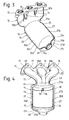
Der schematisch in den Figuren 1, 2 und 5 gezeichnete
Benzin-Verbrennungsmotor 1 beisitzt ein Motorgehäuse 2, mehrere
Zylinder und mindestens zwei, nämlich beispielsweise
drei Abgasausgänge 3 mit je einer Öffnung. Jeder Abgasausgang
3 definiert eine gerade Achse 4. Die Achsen 4 der verschiedenen
Abgasausgänge 3 sind parallel zueinander und liegen beispielsweise
in einer gemeinsamen Ebene. Die Achsen 4 sind in
den Figuren 2 und 5 horizontal gezeichnet, können jedoch auch
vom Motorgehäuse weg nach unten geneigt sein. Eine Abgasanlage
weist eine auch separat in den Figuren 3, 4 und 6 ersichtliche
Abgasvorrichtung 11 mit einem Auspuffkrümmer 12
und einem Katalysator 13 auf.The schematically drawn in Figures 1, 2 and 5
Gasoline
Der Auspuffkrümmer 12 hat mindestens zwei und nämlich
drei in ihren Längsrichtungen mindestens teil- und stellenweise
gebogene Zuleitungen 15 zum Verbinden der Abgasausgänge
3 mit dem Katalysator 13. Der Auspuffkrümmer 12 weist einen
für alle Zuleitungen 15 gemeinsamen Anschlussflansch 17 auf.
Dieser besitzt für jede Zuleitung 15 eine beispielsweise
kreisförmige Öffnung. Die Zuleitungen 15 sind im wesentlichen
doppelwandig und haben eine äussere Wand 19 und eine innere
Wand 20. Die Wände 19, 20 der Zuleitungen haben im Querschnitt
kreisförmige in die genannten Öffnungen des Anschlussflanschs
hineinragende Endabschnitte. Diese liegen
dort aneinander und an den Begrenzungen der Öffnungen an und
sind dicht sowie starr miteinander und mit dem Anschlussflansch
verbunden. Die Öffnungen des Anschlussflanschs und
die in diese hineinragenden Wände der Zuleitungen bilden zusammen
die Abgaseingänge 21 der Zuleitungen. Der Anschlussflansch
17 ist mit Befestigungsmitteln 23, nämlich mit zum
Teil in Fig. 1 sowie in den Figuren 2 und 5 gezeichneten,
Durchgangslöcher des Anschlussflanschs durchdringenden
Schrauben lösbar am Motorgehäuse 2 befestigt.The
Der Katalysator besitzt ein Gehäuse 25 mit einer Gehäuse-Wand
27. Diese hat in der Strömungsrichtung des Abgases der
Reihe nach einen Eingangsabschnitt 27a, einen Hauptabschnitt
27b, einen Ausgangsabschnitt 27c und einen Kragen 27d. Der
Hauptabschnitt 27b ist im wesentlichen parallel zu einer von
ihm definierten, geraden Achse 28 sowie im allgemeinen
zylindrisch und im Querschnitt beispielsweise im allgemeinen
ungefähr oval und/oder elliptisch. Der Eingangsabschnitt 27a
verbindet die drei Zuleitungen 15 mit dem Hauptabschnitt 27b
und erweitert sich beispielsweise in mindestens einem
Längsschnitt zum Hauptabschnitt 27b hin. Der Ausgangsabschnitt
27c ist im allgemeinen trichterförmig und verjüngt
sich vom Hauptabschnitt 27b weg. Der Kragen 27d hat einen
kreisförmigen Umriss, ist im wesentlichen zylindrisch
und/oder leicht konisch und begrenzt eine kreisförmige Öffnung.
Die Achse 28 bildet mit der Achse 4 einen Winkel α, der
mindestens 90°, höchstens 180° und beispielsweise 100° bis
150° beträgt. The catalytic converter has a
Die Abschnitte 27a, 27b, 27c, 27d der Gehäuse-Wand 27 und
die äusseren Wände 19 aller Zuleitungen 15 sind zusammen aus
Abschnitten einer ersten, oberen Schale 31 und einer zweiten,
unteren Schale 32 gebildet. Jede dieser Schalen 31, 32
besteht aus einem einstückigen metallischen Körper. Jede
dieser Schalen bildet im Querschnitt ungefähr eine Hälfte der
Abschnitte 27a, 27b, 27c, 27d der Gehäuse-Wand 27 und auch
ungefähr eine Hälfte der äusseren Wände 19 der drei
Zuleitungen 15. Jede Schale 31, 32 hat einen im Querschnitt
lückenlos zusammenhängenden Hauptabschnitt 31a bzw. 32a, der
ungefähr die Hälfte der Gehäuse-Wand 27 und einen Bereich der
äusseren Wände 19 der mit der Gehäuse-Wand 27 verbundenen
Endabschnitte der Zuleitungen 15 bildet. Jede Schale 31, 32
hat ferner drei sich von ihrem Hauptabschnitt 31a bzw. 32a
bis zum Anschlussflansch 17 erstreckende, fingerförmige Abschnitte
31b bzw. 32b, die im Querschnitt durch freie Zwischenräume
voneinander getrennt und je einer der Zuleitungen
15 zugeordnet sind. Die Hauptabschnitt 31a, 32a und die fingerförmigen
Abschnitte 31b, 32b Schale 31 bzw. 32 haben je
einen im Querschnitt gewölbten und mindestens stellenweise
gebogenen Mittelabschnitt 31c bzw. 32c und Randabschnitte 31d
bzw. 32d. Die Randabschnitte 32d der zweiten Schale 32 sind
gemäss den Figuren 6 und 7 ungefähr L-förmig abgewinkelt oder
abgebogen. Die Randabschnitte 31d der ersten Schale 31
schliessen dagegen ungefähr stetig sowie glatt an die
gewölbten Mittelabschitte 31c an und ragen in die von
L-förmigen Randabschnitten 32d gebildeten Winkel oder Kehlen
hinein.The
Der Hauptabschnitt 27b der Gehäuse-Wand umschliesst im
Querschnitt Katalysatormittel 35 zur katalytischen Behandlung
und Reinigung des Abgases. Die Katalysatormittel 35 besitzen
beispielsweise einen im Querschnitt ungefähr ovalen und/oder
elliptischen, im wesentlichen zylindrischen Katalysatorkörper
36 mit einer Abgaseintrittsfläche 36a sowie einer
Abgasaustrittsfläche 36b. Die Flächen 36a, 36b sind eben und
rechtwinklig zur Achse 28. Der Katalysatorkörper besitzt
beispielsweise ein Substrat aus Keramik mit einer Vielzahl
von axialen Durchgängen für das Abgas. Die die Durchgänge
begrenzenden Flächen des Substrats sind mit Überzügen
versehen, die zum grössten Teil aus porösem Aluminiumoxid
bestehen und ferner mindestens ein katalytisch aktives
Material, beispielsweise Platin und Iridium aufweisen.The
Das Gehäuse 25 enthält ferner eine hitzebeständige Zwischenlage
37, die zwischen der Aussenfläche des Katalysatorkörpers
36 und der Innenfläche des Hauptabschnitts 27b des
Gehäuse-Wand angeordnet ist, den Katalysatorkörper im Querschnitt
umschliesst sowie Schwingungsdämpfern hält und bei
beiden Enden von diesem in axialer Richtung ein wenig über
diesen hinausragt. Die Zwischenlage 37 besteht aus einem bis
mindestens zur Betriebstemperatur der Katalysatormittel
hitzebeständigen, wärmeisolierenden und beispielsweise
elastisch deformierbaren, insbesondere radial komprimierbaren,
schichtförmigen Material. Die Zwischenlage 37 besteht
zum Beispiel aus einer Matte mit anorganischen Fasern, mineralischen
Plättchen, die bei der ersten Erhitzung aufgebläht
werden, und einem Bindemittel. Die Zwischenlage könnte jedoch
auch mindestens eine Lage eines Drahtgeflechts oder Drahtgewirkes
und ein wärmeisolierendes Füllmaterial aufweisen.The
Das Gehäuse 25 enthält ferner eine trichterförmige Eingangs-Innenwand
41, die als Abgas-Sammler und -Verteiler
dient und sich zum grössten Teil innerhalb des Eingangsabschnitts
27a des Gehäuses befindet. Die Eingangs-Innenwand
41 hat am sich entlang dem Strömungsweg näher beim Anschlussflansch
17 befindenden Ende einen kurzen, ungefähr
zylindrischen Endabschnitt mit einer besonders deutlich in
Fig. 6 ersichtlichen Eintrittsöffnung 41a. Diese hat einen
länglichen, mehr oder weniger rechteckförmigen Umriss, wobei
die schmäleren Rechteckseiten mindestens zum Teil durch Bogen
ersetzt sind. Die trichterförmige Eingangs-Innenwand hat
ferner einen sich in der Strömungsrichtung erweiternden
Mittelabschnitt und an ihrem sich stromabwärts befindenden
Ende einen, kurzen im wesentlichen zylindrischen, im Querschnitt
ungefähr ovalen und/oder elliptischen Endabschnitt
mit einer Austrittsöffnung. Dieser Endabschnitt erstreckt
sich bis mindestens annähernd zur Abgaseintrittsfläche des
Katalysatorkörpers 36, hat eine mindestens ungefähr mit der
Mantel- oder Umfangsfläche des Katalysatorkörpers fluchtende
Aussenfläche und wird mindestens zum Teil von der Zwischenlage
37 umschlossen. Die Eingangs-Innenwand 41 besteht aus
einer ersten Schale 43 und einer zweiten Schale 44. Jede
Schale 43, 44 besteht aus einem einstückigen, metallischen
Körper, d.h. Blechteil und bildet mindestens ungefähr eine
Hälfte der Eingangs-Innenwand 41. Jede Schale 43, 44 hat
einen im Querschnitt gewölbten Mittelabschnitt 43a bzw. 44a
und bei beiden axialen Längsrändern von diesem einen Randabschnitt
43b bzw. 44b. Diese Randabschnitte und/oder Randflansche
sind im Querschnitt im wesentlichen L-förmig. Wie es in
Fig. 6 ersichtlich ist, umgreifen die L-förmigen Randabschnitte
32d, 44b, 43b einander. Die Randabschnitte 31d der
Schale 31 ragen in die von den Randabschnitten 43b gebildete
Kehlen hinein. Die Eingangs-Innenwand 41 und der im Querschnitt
von ihr umschlossene Innenraumbereich oder Durchgang
haben eine mindestens annähernd mit der Achse 28 zusammenfallende
Mittelachse.The
Die innere Wand 20 jeder Zuleitung 15 besteht aus einem
einstückigen, mindestens stellenweise gebogenen Rohr. Der Anschlussflansch
17, die inneren Wände 20 und die Schalen 31,
32, 43, 44 bestehen alle aus einem metallischen Material beispielsweise
Stahl. Die äusseren und inneren Wände 19, 20 der
Zuleitungen sind mit dem Anschlussflansch verschweisst. Die
beiden Schalen 31, 32 sind bei ihren Randabschnitten 31d, 32d
durch in den Figuren 6 und 7 ersichtliche Schweissverbindungen
47 fest und dicht miteinander verbunden. Bei dem die Eingangs-Innenwand
41 enthaltenden Längsbereich des Gehäuses 27
verbinden die Schweissverbindungen 47 auch die Randabschnitte
der Schalen 43, 44 der Eingangs-Innenwand 41 mit den Randabschnitten
der Schalen 31, 32 des Gehäuses.The
Der in die Eintrittsöffnung 41a der Eingangs-Innenwand 41
hineinragenden Endabschnitt der inneren Wand 20 der mittleren
Zuleitung 15 ist gemäss der Fig. 6 im wesentlichen viereckförmig,
d. h. rechteck- oder quadratförmig und hat vier im
wesentlichen ebene Wandabschnitte. Die die Eintrittsöffnung
41a hineinragenden Endabschnitte der inneren Wände 20 der
beiden äusseren Zuleitungen 15 haben ebene und gebogene
Wandabschnitte. Die inneren Wände 20 liegen in dem von der
Eingangs-Innenwand 41 begrenzten Innenraumbereich mit ebenen
Wandabschnitten paarweise aneinander an und passen mindestens
annähernd spielfrei in die Eintrittsöffnung 41a hinein, so
dass sie diese zusammen im Querschnitt mindestens annähernd
ausfüllen und eine annähernd dichte Verbindung der Innenwände
20 der Zuleitungen 15 mit der Eingangs-Innenwand 41 ergeben.
Die in die Eintrittsöffnung 41a hineinragenden Endabschnitte
der inneren Wände 20 sind jedoch in ihrer Längsrichtung bezüglich
der Eingangs-Innenwand 41 verschiebbar.The one in the entrance opening 41a of the entrance
Das Gehäuse 25 enthält noch eine im allgemeinen trichterförmige
Ausgangs-Innenwand 49. Diese ist stromabwärts von den
Katalysatormitteln 35 angeordnet und befindet sich zum grössten
Teil im Ausgangsabschnitt 27c der Gehäuse-Wand 27. Die
Ausgangs-Innenwand 49 hat an ihrem sich stromaufwärts befindenden
Ende einen kurzen, im Querschnitt ungefähr ovalen
und/oder elliptischen Endabschnitt, der mindestens annähernd
an den Katalysatorkörper 36 anschliesst, eine ungefähr mit
dessen Mantel- und/oder Umfangsfläche fluchtende Aussenfläche
hat und mindestens zum Teil von der Zwischenlage 37 umschlossen
ist. An diesen zylindrischen Endabschnitt schliesst ein
sich verjüngender Mittelabschnitt an, auf den ein kurzer, im
Querschnitt kreisförmiger, ungefähr zylindrischer Endabschnitt
folgt, der sich ungefähr bis zum stromabwärts angeordneten
Ende des Gehäuses erstreckt, eine kreisförmige
Öffnung begrenzt und zusammen mit dem Kragen 27d den für alle
Zuleitungen gemeinsamen Abgasausgang des Katalysators bildet.
Die Innenwand 49 besteht aus einem einstückigen Körper aus
einem metallischen Material, nämlich Stahl. Eine aus einem
Rohr aus einem metallischen Material, nämlich Stahl, bestehende
Ableitung 51 übergreift das sich stromabwärts befindende
Ende der Ausgangs-Innenwand 49 und ist dicht sowie fest
mit der Ausgangs-Innenwand 49 und dem durch Abschnitte der
beiden Schalen 31, 32 gebildeten Kragen 27d verbunden,
nämlich verschweisst.The
Eine metallische, aus Stahl bestehende Buchse 55 besitzt
ein axiales, durchgehendes Loch mit einem Innengewinde, ragt
durch stromaufwärts von den Katalysatormitteln 35 angeordnete
Löcher der Schalen 31 und 43 hindurch und ist dicht mit diesen
Schalen verschweisst. Eine Lambdasonde 56 ist in das Innengewinde
der Buchse 55 eingeschraubt und ragt durch diese
hindurch in den von der Eingangs-Innenwand 41 umschlossenen
Innenraumbereich hinein. Eine Buchse 57 ist stromabwärts von
den Katalysatormitteln 35 in ein Loch der Ableitung 51 eingeschweisst
und hat ebenfalls ein axiales Durchgangsloch mit
einem Innengewinde, in das eine in die Ableitung 51 hineinragende
Lambdasonde 58 eingeschraubt ist.Has a metallic, made of
Die inneren Wände 20 der Zuleitungen 15 sind von den äusseren
Wänden 19 der Zuleitungen im wesentlichen und zum
grössten Teil - d.h. abgesehen von ihren mit dem Anschlussflansch
verbundenen Endabschnitten - durch einen zusammenhängenden
Zwischenraum 61 getrennt. Der Zwischenraum 61
trennt auch den grössten Teil der trichterförmigen Eingangs-Innenwand
41 von der durch Abschnitte der Schalen 31, 32
gebildeten Wandung des Gehäuses 27. Die trichterförmige
Ausgangs-Innenwand 49 ist im wesentlichen und zum grössten
Teil durch einen Zwischenraum 62 von der durch Abschnitte der
Schalen 31, 32 gebildeten Wandung des Gehäuses getrennt. Die
Zwischenräume 61, 62 sind im wesentlichen frei sowie hohl und
enthalten im wesentlichen stillstehende Luft und/oder im
wesentlichen stillstehendes Abgas.The
Bei der Herstellung der Abgasvorrichtung 11 werden zur
Bildung der Schalen 31, 32, 43, 44 und der Ausgangs-Innenwand
49 dienende, ebene Blechteile zugeschnitten, beispielsweise
ausgestanzt. Diese Blechteile werden dann durch plastisches
Umformen beispielsweise mindestens zum Teil durch Tiefziehen,
derart umgeformt, dass sie die gewünschten Formen erhalten.In the manufacture of the
Die inneren Wände 20 der Zuleitungen 15 werden zum Beispiel
aus ursprünglich geraden, im Querschnitt kreisförmigen
Rohren gebildet. Diese Rohre werden dann durch plastisches
Umformen in die gewünschten Formen gebracht. Die Rohre können
beispielsweise entlang ihren Achsen gebogen und bei ihren bei
der fertigen Abgasvorrichtung 11 in die trichterförmige Eingangs-Innenwand
41 hineinragenden Endabschnitten durch plastisches
Umformen auf die vorgesehenen Querschnittsformen gebracht
werden. Die inneren Wände 20 können jedoch stattdessen
auch aus ursprünglich einem kleineren Durchmesser aufweisenden
Rohren gebildet werden, die zuerst ungefähr in die gewünschte
Form gebogen, danach in Form-Werkzeuge bzw. Matrizen
eingebracht und im sogenannten Innenhochdruck-Umformverfahren
durch eine in die Rohre hineingepumpte Flüssigkeit erweitert
und in die durch Form-Werkzeuge bzw. Matrizen festgelegten
Formen gebracht werden.The
Zum Zusammenbauen einer Abgasvorrichtung 1 können zum
Beispiel die inneren Wände 20, die erste Schale 43 der Eingangs-Innenwand
41, die Buchse 55, die von der Zwischenlage
37 umhüllten Katalysatormittel 35 und die beispielsweise
schon mit der Ableitung 51 verschweisste Ausgangs-Innenwand
49 in die erste Schale 31 des Gehäuses eingesetzt werden. Die
Buchse 55 wird während oder nach diesem Zusammensetz-Vorgang
mindestens mit der zur Eingangs-Innenwand 41 gehörenden
Schale 43 und eventuell auch schon mit der zum Gehäuse gehörenden
Schale 31 verschweisst. Nach dem Verschweissen der
Buchse 55 mit der ersten Schale 43 wird auch die zweite
Schale 44 der Eingangs-Innenwand 41 ein- und/oder aufgesetzt
und das Gehäuse 25 durch Aufsetzen der zweiten Schale 32 geschlossen.
Danach werden die vier Schalen 31, 32, 43, 45 bei
den Randabschnitten 31d, 32d, 43b, 44b dicht miteinander verschweisst,
wobei die Schweissverbindungen 47 gebildet werden.
Des weiteren werden noch die Wände 19, 20 der Zuleitungen 15
mit dem Anschlussflansch 17 und die Ableitung 51 mit den
Schalen 31, 32 verschweisst. Ferner werden die Buchsen 55, 57
mit der Schale 31 bzw. Ableitung 51 verschweisst, falls dies
nicht bereits vorher geschehen ist.To assemble an
Die Abgasvorrichtung 11 und insbesondere die äusseren
Wände der Zuleitungen 15 sowie das Gehäuse 25 können also bei
der serienmässigen Fabrikation aus relativ wenig ursprünglich
separaten Teilen gebildet und schnell, einfach sowie
wirtschaftlich zusammengebaut werden. Dabei müssen
insbesondere auch nur relativ wenig Schweissverbindungen
gebildet werden.The
Der Ausgang des Katalysators 13 kann über die Ableitung
51 mit weiteren Teilen einer Abgasanlage, insbesondere mit
mindestens einem Schalldämpfer verbunden werden. Wenn der Anschlussflansch
17 der Abgasvorrichtung lösbar und dicht am
Motorgehäuse 2 befestigt ist und der Verbrennungsmotor 1 beim
Betrieb heisses Abgas erzeugt, strömt dieses stossweise bei
den Abgaseingängen 21 in die von inneren Wänden 20 der Zuleitungen
15 begrenzten Durchgänge. Das Abgas strömt danach
durch diese Durchgänge und den von der Eingangs-Innenwand 41
begrenzten, sich in der Strömungsrichtung erweiternden Innenraumbereich
und/oder Durchgang zur Abgaseintrittsfläche 36a
des Katalysatorkörpers 36 der Katalysatormittel 35. Die
trichterförmige Eingangs-Innenwand 41 dient dabei als Abgas-Sammler
und -Verteiler, sammelt das stossweise abwechselnd
durch die verschiedenen Zuleitungen 15 in das Gehäuse 25 einströmende
Abgas und verteilt dieses auf die Abgaseintrittsfläche
36a des Katalysatorkörpers 36. Die Eingangs-Innenwand
leitet das Abgas dabei im allgemeinen und insbesondere im
zentralen Bereich, d.h. in der Umgebung der Achse 28,
parallel zu dieser sowie ungefähr rechtwinklig zur Abgas-eintrittsfläche
36a gegen die letztere. Das Abgas strömt
danach durch die Durchgänge des Katalysatorkörpers hindurch
und wird dabei katalytisch behandelt und gereinigt. Da bei
der Abgasaustrittsfläche 36b des Katalysatorkörpers 36 aus
diesem ausströmende Abgas strömt danach durch den sich in der
Strömungsrichtung verjüngenden Innenraumbereich oder Durchgang
der trichterförmigen Ausgangs-Innenwand 49 zur Ableitung
51. Die beiden Lambdasonden 56 und 58 können den Sauerstoffgehalt
des Abgases stromaufwärts bzw. stromabwärts von den
Katalysatormitteln 35 messen.The output of the
Die kompakte Ausbildung der Abgasvorrichtung 11 ermöglicht,
den Katalysator 13 nahe beim Verbrennungsmotor 1 anzuordnen
und durch relativ kurze Zuleitungen mit diesem zu verbinden.
Der Luft und/oder mehr oder weniger ruhendes Abgas
enthaltende Zwischenraum 61 isoliert die das strömende Abgas
führenden, inneren Wände 20 der Zuleitungen 15 und die Eingangs-Innenwand
41 thermisch gegen die Schalen 31, 32. Das
Abgas gibt daher zwischen dem Anschlussflansch 17 und den
Katalysatormitteln 35 nur wenig Wärme an die Umgebung ab und
wird dementsprechend zwischen dem Verbrennungsmotor und dem
Katalysatormitteln nur wenig abgekühlt. Dies ergibt bei einem
Kalt-Start den Vorteil, dass die ursprünglich die Umgebungstemperatur
aufweisenden Katalysatormittel rasch auf die für
eine wirkungsvolle katalytische Behandlung und Reinigung des
Abgases erforderliche Temperatur erhitzt werden. Der
Katalysatorkörper 36 und die Ausgangs-Innenwand 49 werden
durch die Zwischenlage 37 sowie den Luft und/oder
stillstehendes Abgas enthaltenden Zwischenraum 62 thermisch
gegen die Schalen 31, 32 des Gehäuses isoliert. Die äusseren
Wände 19 der Zuleitungen 15 und die Wandung des Gehäuses 25
bleiben daher verhältnismässig kühl, so dass nötigenfalls
hitzeemfindliche Teile relativ nahe bei der Abgasvorrichtung
11 angeordnet werden können. Im übrigen beansprucht die kompakt
ausgebildete Abgasvorrichtung 11 nur wenig Platz.The compact design of the
Das beim Betrieb der Abgasvorrichtung durch diese hindurch
geleitete, heisse Abgas verursacht eine vorübergehende
Erhitzung und Dehnung der verschiedenen Teile der Abgasvorrichtung.
Die durch unterschiedliche Temperaturänderungen
verursachten, unterschiedlichen Längenänderungen der äusseren
Wände 19 und der inneren Wände 20 der Zuleitungen 15 können
dabei durch die verschiebbare Verbindung der inneren Wände 20
mit der Eingangs-Innenwand 41 ausgeglichen werden, ohne dass
nennenswerte Spannungen entstehen. Zwischen dem von der Zwischenlage
37 im Gehäuse 25 gehaltenen Katalysatorkörper 36
und den diesem zugewandten Enden der Innenwände 41 und 49
sind bei kaltem Katalysator vorzugsweise schmale Zwischenräume
vorhanden. Diese können durch vorübergehende Temperaturerhöhungen
verursachte Längenänderungen des Katalysatorkörpers
36 und vor allem der Innenwände 41, 49 aufnehmen,
ohne Spannungen zu erzeugen. Die Temperaturänderungen verursachen
dementsprechend keine Risse oder Brüche von irgendwelchen
Wänden oder sonstigen Teilen.That through the operation of the exhaust device
conducted, hot exhaust gas causes a temporary
Heating and expansion of the various parts of the exhaust device.
By different temperature changes
caused different length changes of the
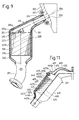
Die in der Fig. 8 ersichtliche Abgasvorrichtung 111 ist
weitgehend ähnlich wie die Abgasvorrichtung 11 ausgebildet,
unterscheidet sich jedoch von dieser dadurch, dass sie vier
doppelwandige Zuleitungen 115 hat. Ferner ist die nicht
sichtbare Eingangs-Innenwand eventuell nur in einigen und
nicht in allen Längsschnitten trichterförmig, so dass ihr
Mittelabschnitt sich dementsprechend nur in einigen
Längsschnitten zu den Katalysatormitteln hin erweitert.The
Der teilweise in Fig. 9 ersichtliche Benzin-Verbrennungsmotor
201 ist beispielsweise als V-Motor ausgebildet und hat
ein Motorgehäuse 202 mit mehreren Abgasausgängen 203, die zueinander
parallele, vom Motor weg nach unten geneigte Achsen
204 haben. Die ebenfalls in Fig. 9 ersichtliche Abgasvorrichtung
211 besitzt einen Auspuffkrümmer 212 mit doppelwandigen
Zuleitungen 215 und einem Katalysator 213 mit einem Gehäuse
225. Dieses hat eine Gehäuse-Wand 227 mit einem
Eingangsabschnitt 227a und einem Hauptabschnitt 227b. Der
letztere definiert eine gerade, beispielsweise fast oder
genau vertikale Achse 228, die mit den Achsen 204 einen
Winkel a im Bereich von etwa 100° bis 150° bildet. Der
Hauptabschnitt 227b enthält Katalysatormittel 235 mit einem
Katalysatorkörper 236. Dieser hat eine ebene, zur Achse 228
rechtwinklige Abgaseintrittsfläche 236a. Diese bildet mit den
zueinander parallelen Achsen 204 einen Winkel β, der 90°
kleiner als der Winkel α ist, dementsprechend ungefähr im
Bereich von 10° bis 60° liegt und zum Beispiel ungefähr 15°
und 45° beträgt. Das Gehäuse 225 enthält eine stromaufwärts
vom Katalysatorkörper angeordnete Eingangs-Innenwand 241.The gasoline internal combustion engine partially shown in FIG. 9
201 is designed and has, for example, a V engine
an
Die Abgasvorrichtung 211 ist im allgemeinen ähnlich ausgebildet
wie die Abgasvorrichtung 11, unterscheidet sich von
dieser jedoch dadurch, dass der Eingangsabschnitt 227a der
Gehäuse-Wand 227 und die Eingangs-Innenwand 241 im
gezeichneten Axialschnitt derart gebogen und/oder abgewinkelt
sind, dass sie teilweise mehr oder weniger entlang einer
geraden, zu den Achsen 204 parallelen Achse verlaufen
und/oder eine solche Achse definieren. Bei der Verwendung der
Abgasverrichtung 211 strömt das Abgas dementsprechend im
allgemeinen und insbesondere im mittleren Querschnittsbereich
des von der Innenwand 241 begrenzten Innenraumbereiches
und/oder Durchgangs mehr oder weniger parallel zu den Achsen
204 gegen die Abgaseintrittsfläche 236a. Das Abgas hat also
in einem sich geringfügig stromaufwärts von der
Abgaseintrittsfläche 236a befindenden Innenraumbereich im
allgemeinen und zu einem grossen Teil eine Strömungsrichtung,
die gegen die Abgaseintrittsfläche 236a geneigt ist und mit
dieser ungefähr den von 90° verschiedenen Winkel β bildet.
Dies trägt zu einer gleichmässigen Verteilung des Abgases auf
die Abgaseintrittsfläche 236a und die Durchgänge des
Katalysatorkörpers 236 bei. Das sich stromabwärts befindende
Ende des Gehäuses ist mit einer Ableitung 251 versehen, die
ein kurzes Rohrstück und einen Flansch für die lösbare
Verbindung mit dem nachfolgenden Teil der Abgasanlage
aufweist.The
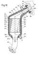
Der teilweise in Fig. 10 dargestellte Benzin-Verbrennungsmotor
301 hat ein Motorgehäuse 302 mit Abgasausgängen
303, deren Durchgänge in der Abgas-Strömungsrichtung nach
unten geneigt sind und Achsen 304 definieren. Die ebenfalls
in Fig. 10 ersichtliche Abgasvorrichtung 311 weist einen Auspuffkrümmer
312 und einen Katalysator 313 auf. Der Auspuffkrümmer
312 besitzt mehrere Zuleitungen 315 und einen für
diese gemeinsamen Anschlussflansch 317. Jede Zuleitung hat
eine äussere Wand 319 und eine innere Wand 320. Der Katalysator
313 weist ein Gehäuse 325 mit einer Gehäuse-Wand 327
auf. Diese besitzt entlang dem Abgas-Strömungsweg der Reihe
nach einen Eingangsabschnitt 327a, einen Hauptabschnitt 327b,
einen Ausgangsabschnitt 327c und einen Kragen 327d. Die
Abgasvorrichtung 311 weist wiederum zwei einstückige, miteinander
verschweisste Schalen 331, 332 auf, von denen jede
ungefähr die Hälfte der äusseren Wände 319 der Zuleitungen
315 und die Abschnitte 327a bis 327d der Gehäuse-Wand 327
bildet. Der Hauptabschnitt 327b der Gehäuse-Wand 327 definiert
eine gerade Achse 328 und enthält Katalysatormittel 335
mit einem Katalysatorkörper 336, eine Eingangs-Innenwand 341
und eine Ausgangs-Innenwand 349. Die Eingangs-Innenwand 341
hat an ihren dem Motorgehäuse 302 sowie dem Anschlussflansch
317 zugewandten Ende einen kurzen, meistens annähernd zu den
Achsen 304 parallelen, eine Eintrittsöffnung 341a begrenzenden
Endabschnitt. Die inneren Wände 320 der Zuleitungen 315
bestehen wie bei der Abgasvorrichtung gemäss Fig. 9 aus kurzen,
geraden Rohren und ragen möglichst genau passend,
parallel zu ihren Längsrichtungen und zu den Achsen 304 verschiebbar
durch die Eintrittsöffnung 341a in dem von der
Eingangs-Innenwand 341 umschlossenen Innenraumbereich hinein.
Der Ausgang des Katalystors ist mit einer Ableitung 351
verbunden.The gasoline internal combustion engine partially shown in FIG. 10
301 has a
Die Abgasvorrichtung 311 besitzt zusätzlich zu auch bei
den Abgasvorrichtungen 11, 111, 211 vorhandenen Wänden und
sonstigen Teilen noch einen Kühl-Mantel 370. Dieser erstreckt
sich mindestens über die grössten Teile der Längen der
Zuleitungen 315 und des Gehäuses 325. Der Kühl-Mantel 370
erstreckt sich nämlich vom Anschlussflansch 317 bis zum
Ausgang des Katalysators 313, d.h. bis zum Kragen 327d des
Gehäuses 327, und also im wesentlichen über die gesamte Länge
der Zuleitungen sowie des Gehäuses. Der Kühl-Mantel 370
bildet sowohl Kühl-Wände der Zuleitungen 315 als auch Kühl-Wände
des Gehäuses 325 und umschliesst im Querschnitt die von
den beiden Schalen 331, 332 gebildeten, äusseren Wände 319
der Zuleitungen 315 sowie die ebenfalls von den beiden
Schalen 331, 332 gebildete Gehäuse-Wand 327. Der Kühl-Mantel
370 ist aus zwei einstückigen, metallischen, beispielsweise
aus rostfreien Stahl bestehenden, äusseren Schalen 371 und
372 gebildet. Jede dieser Schalen 371, 372 bildet in
Querschnitten ungefähr eine Hälfte des Kühl-Mantels. Jede
Schale 371, 372 hat beispielsweise analog wie die Schalen 31,
32 der Abgasvorrichtung 11 einen im Querschnitt gewölbten
sowie lückenlos zusammenhängenden Hauptabschnitt und für jede
Zuleitung einen mit dem Anschlussflansch 17 verbundenen,
fingerförmigen Abschnitt, wobei diese fingerförmigen
Abschnitte durch Zwischenräume voneinander getrennt sind. Der
Anschlussflansch 317 ist zum Beispiel aus zwei ursprünglich
separaten, ebenen, aneinander anliegenden, metallischen
Platten gebildet und hat für jeden Abgasausgang des Motors
ein beide Platten durchdringendes Loch. Die innere Wand 320,
die äussere Wand 319 jeder Zuleitung 315 und die dieser
Zuleitung zugeordneten, fingerförmigen Abschnitte der beiden
Schalen 371, 372 ragen in ein Loch des Anschlussflanschs 317
hinein und sind innerhalb diesem alle durch eine
Schweissverbindung dicht miteinander sowie mit dem
Anschlussflansch 317 verbunden. Dabei verbindet diese
Schweissverbindung oder Schweissnaht auch die beiden Platten
des Anschlussflansches 317 miteinander. Die sich beim Kragen
327d der Gehäuse-Wand 327 befindende Enden der Schalen 371,
372 liegen an diesem Kragen an und sind dort durch eine
einzige Schweissverbindung oder Schweissnaht dicht mit den
Schalen 331, 332 der Gehäuse-Wand 327 und mit der Ableitung
351 verbunden. Die beiden Schalen 371, 372 des Kühl-Mantels
haben bei ihren Längsrändern und bei den Zwischenräumen
zwischen den fingerförmigen Abschnitten fest sowie dicht
miteinander verbundene Randabschnitte, die beispielsweise
ähnlich ausgebildet und miteinander verschweisst sind, wie
die Randabschnitte 31d, 32d der Schalen 31, 32 des zuerst
beschriebenen Ausführungsbeispiels. Der Kühl-Mantel 370 ist
zwischen seinen fingerförmigen, mit dem Anschlussflansch 317
verschweissten Abschnitten und seinen sich beim Ausgang des
Katalysators befindenden Ende durch einen Zwischenraum 373
von den beide Schalen 331, 332 getrennt. Der Zwischenraum 373
hat dabei einen die Gehäuse-Wand 327 im Querschnitt
vollständig umschliessenden Bereich und mit diesem
zusammenhängende Bereiche, die je eine der äusseren Wände 319
der Zuleitungen 315 im Querschnitt vollständig umschliessen.
Der Kühl-Mantel 370 ist mit zwei Kühlmittel-Anschlüssen 374,
375 versehen, die in den Zwischenraum 373 mündenden
Durchgänge haben. Der Anschluss 374 ist in der Nähe der
höchsten Stelle des Zwischenraums 373, beispielsweise in der
Nähe des mit den fingerförmigen Abschnitten verbundenen Endes
des im Querschnitt zusammenhängenden Hauptabschnitts des
Kühl-Mantels auf der oberen Seite von diesem angeordnet. Der
Anschluss 375 ist beim Ausgang des Katalysators in der Nähe
der tiefsten Stelle des Zwischenraums 373 angeordnet.The
Soweit vorgängig nichts anderes geschrieben wurde, weist
die Abgasvorrichtung 311 ähnliche Bestandteile auf, wie die
vorher beschriebenen Abgasvorrichtungen.Unless otherwise previously written, points
the
Bei der Benutzung der Abgasvorrichtung 311 wird das Abgas
ähnlich wie bei der in Fig. 9 dargestellten Abgasvorrichtung
211 im allgemeinen geneigt zur Abgas-Eintrittsfläche der
Katalysatormittel in die Nähe dieser Abgas-Eintrittfläche
geleitet. Ferner wird ein vorzugsweise flüssiges Kühlmittel
in der durch Pfeile angedeuteter Weise beim Anschluss 374 in
der Zwischenraum 373 hinein und beim Anschluss 375 wieder aus
dem Zwischenraum 373 heraus geleitet. Dadurch werden die
Temperaturen der Schalen 331, 332 sowie der Schalen 371, 372
des Kühl-Mantels und die Wärmeabgabe an die Umgebung der
Abgasvorrichtung 311 beträchtlich reduziert. Da die beiden
Schalen 331, 332 von der inneren Wände 320 der Zuleitungen,
der Eingangs-Innenwand 341 und sowie den Katalysatormitteln
335 im wesentlichen überall durch Gas oder ein
wärmeisolierendes Material enthaltende Zwischenräume getrennt
sind, werden die Katalystormittel und das beim Betrieb des
Motors von diesem zu den Katalysatormitteln sowie durch diese
hindurch strömende Abgas durch das Kühlmittel höchstens
geringfügig abgekühlt. Die Kühlung der Abgasvorrichtung hat
daher praktisch keinen negativen Einfluss auf die
katalytische Behandlung des Abgases.When using the
Die in Fig. 11 ersichtliche Abgasvorrichtung 411 besitzt
Zuleitungen 415 mit einer äusseren Wand 419 sowie einer
inneren Wand 420 und ein Gehäuse 425 mit einer (äusseren)
Gehäuse-Wand 427. Die letztere hat einen Eingangsabschnitt
427a, Hauptabschnitt 427b und Ausgangsabschnitt 427c. Die
äusseren Wände der Zuleitungen 419 und die Gehäuse-Wand 427
sind wiederum durch zwei miteinander verschweisste Schalen
431 und 432 gebildet. Das Gehäuse 425 enthält eine Gehäuse-
und/oder Katalysator-Innenwand 440. Diese erstreckt sich
annähernd über die ganze Länge des Gehäuses 425 und bildet
eine als Abgas-Sammler und -Verteiler dienende Eingangs-Innenwand
440a, eine Haupt- und/oder Mittel-Innenwand 440b
und eine Ausgangs-Innenwand 440c. Diese drei Innenwände 440a,
440b, 440c befinden sich in den im Querschnitt vom Eingangsabschnitt
427a bzw. vom Hauptabschnitt 427b bzw. vom Ausgangsabschnitt
427c der Gehäuse-Wand 427 umschlossenen Innenraumbereichen
des Gehäuses. Die Haupt- und/oder Mittel-Innenwand
440b ist koaxial zum Hauptabschnitt 427b der Gehäuse-Wand
427, im allgemeinen zylindrisch sowie im Querschnitt
beispielsweise ungefähr kreisförmig oder oval und umschliesst
im Querschnitt Katalysatormittel 435 mit einem Katalysatorkörper
436. Zwischen der Mittel-Innenwand 440b und der
Umfangsfläche des Katalysatorkörpers 436 ist eine deformierbare
Zwischenlage 437 angeordnet. Die Katalysator-Innenwand
440 besteht zum Beispiel aus einem einstückigen Blechteil
oder aus zwei miteinander verschweissten Blechteilen. Die
Eingangs-Innenwand 440a und die Ausgangs-Innenwand 440c haben
im allgemeinen ähnliche Formen wie die Eingangs-Innenwand 41
bzw. die Ausgangs-Innenwand 49 der Vorrichtung 11. Die
Katalysator-Innenwand 440 und die durch einen Abschnitt von
dieser gebildete Eingangs-Innenwand 440a haben jedoch beispielsweise
keine mit den Schalen der Gehäuse-Wand verschweissten
Randabschnitte und sind zum Beispiel nur durch
die zum Halten einer Lambdasonde 456 dienende Buchse 455
starr mit den Schalen der Gehäuse-Wand 427 verbunden. Die
Gehäuse- und/oder Katalysator-Innenwand 440 hat jedoch
mindestens einen durch eine nach aussen ragende Sicke
gebildeten Vorsprung, wobei als Beispiel zwei ringförmige,
entlang dem Umfang der Gehäuse- und/oder Katalysator-Innenwand
440 verlaufende Vorsprünge 440d und 440e gezeichnet
sind. Der Vorsprung 440d befindet sich in der Haupt- und/oder
Mittel-Innenwand 440b in der Nähe von deren sich stromaufwärts
befindendem Ende. Der Vorsprung 440e ist in der Nähe
des sich stromabwärts befindenden Endes der Gehäuse-Wand 427
angeordnet. Die Innenwand 440 wird durch die Vorsprünge 440d,
440e - beispielsweise mit etwas Spiel - zentriert. Der Vorsprung
440d ragt zum Beispiel zwischen zwei nicht
gezeichnete, nach innen vorstehende, aus Sicken gebildete
Vorsprünge des Hauptabschnitts 427b der Gehäuse-Wand 427a
hinein und wird dadurch ein wenig axial verschiebbar oder
annähernd unverschiebbar im Gehäuse gehalten. Der Vorsprung
440e kann sich dagegen frei axial verschieben.The
Die inneren Wände 420 der Zuleitungen 415 sind zum
Beispiel ähnlich verschiebbar mit der Eingangs-Innenwand 440a
verbunden, wie die inneren Wände 20 der Vorrichtung 11 mit
der Eingangs-Innenwand 41. Abhängig von den Formen der
inneren Wände 420 der Zuleitungen und der Verbindungsstelle
der inneren Wände 420 mit der Eingangs-Innenwand kann jedoch
vielleicht mindestens eine der Wände 420 mit der Eingangs-Innenwand
440a verschweisst sein. Eventuell können sogar alle
inneren Wände 420 mit der Eingangs-Innenwand 440a
verschweisst sein. Zwischen den Innenflächen der von den
miteinander verschweissten Schalen 431, 432 gebildeten
äusseren Wänden 419 der Zuleitungen und inneren Wänden von
diesen ist wiederum ein Zwischenraum 461 vorhanden. Die
Gehäuse-Wand 427 und die Gehäuse und/oder Katalysator-Innenwand
440 sind im wesentlichen - d. h. abgesehen von den
Vorsprüngen 440d, 440e und der Buchse 455 - ebenfalls durch
einen freien Zwischenraum 462 getrennt. Dieser hängt bei der
Eingangs-Innenwand 440a mit dem Zwischenraum 461 zusammen und
erstreckt sich bis mindestens annähernd zum sich stromabwärts
befindenden Ende der Gehäuse-Wand 427 d.h. ungefähr bis zum
Vorsprung 440e. Der zwischen dem Hauptabschnitt 427b der
Gehäuse-Wand 427 und dem Mittelabschnitt 440b der
Katalysator-Innenwand 440 vorhandene Bereich des
Zwischenraums 462 ergibt eine zusätzliche Wärmeisolation der
Katalysatormittel. Wenn beim Betrieb heisses Abgas in Kontakt
mit den inneren Wänden 420 der Zuleitungen sowie mit der
Gehäuse- und/oder Katalysator-Innenwand 440 gelangt, können
sich die Wände 420, 440 in allen Richtungen ausdehnen, ohne
dass übermässige Spannungen entstehen, die Risse oder Brüche
verursachen könnten. Soweit vorgängig nicht anders
geschrieben wurde, kann die Vorrichtung 411 ähnlich wie die
Vorrichtung 11 ausgebildet sein.The inner walls 420 of the feed lines 415 are for
Example similarly displaceable with the input inner wall 440a
connected as the
Die Abgasvorrichtungen und deren Herstellung können noch
auf andere Weisen modifiziert werden und können beispielsweise
nur zwei oder mehr als vier Zuleitungen aufweisen. Ferner
können Merkmale von verschiedenen anhand der Figuren beschriebenen
Varianten kombiniert werden. Die in den Figuren 1
bis 9 und 11 gezeichneten Abgasvorrichtungen können
beispielsweise ebenfalls mit einen aus zwei Platten
zusammengesetzten Anschlussflansch und/oder zusätzlich mit
einem Kühl-Mantel versehen werden. Des weiteren könnte der
für alle Zuleitungen gemeinsame Anschlussflansch 17 bzw. 317
durch mehrere, je nur einer einzigen Zuleitung oder nur
einigen der Zuleitungen zugeordnete, separate Flansche
ersetzt werden. Die inneren Wände der Zuleitungen können
eventuell zusammen aus zwei durch Tiefziehen geformten
Schalen gebildet sein, von denen jede ungefähr die Hälfte
einer inneren Wand bildet. Die Eingangs-Innenwand 41, 241,
341 kann statt aus zwei Schalen aus einem einstückigen
Blechteil gebildet werden. Umgekehrt kann die Ausgangs-Innenwand
49 bzw. 349 statt aus einem einstückigen Blechteil
aus zwei miteinander verschweissten Schalen gebildet werden.
Die trichterförmige Ausgangs-Innenwand 49, 349 könnte statt
über die Ableitung 51 bzw. 251, bwz. 351 oder zusätzlich
durch eine Schweissverbindung direkt mit den Schalen 31, 32,
bzw. 331, 332 und eventuell 371, 372 verbunden sein.The exhaust devices and their manufacture can still
can be modified in other ways and can for example
only have two or more than four supply lines. Further
can features of different described with reference to the figures
Variants can be combined. The in Figures 1
to 9 and 11 drawn exhaust devices can
for example also with one of two plates
compound connecting flange and / or additionally with
be provided with a cooling jacket. Furthermore, the
Des weiteren könnten die Katalysatormittel statt nur eines einzigen Katalysatorkörpers beispielsweise zwei in der Strömungsrichtung nacheinander angeordnete Katalysatorkörper aufweisen. Ferner könnte der bzw. jeder Katalysatorkörper aus aufgewickelten oder aufeinander geschichteten, mit Überzügen versehenen Blechelementen gebildet sein.Furthermore, the catalyst agents could be used instead of just one single catalyst body, for example, two in the Direction of flow arranged in succession catalyst body exhibit. Furthermore, the or each catalyst body could be made of wound or layered on top of each other, with covers provided sheet metal elements are formed.
Claims (10)
Applications Claiming Priority (2)
| Application Number | Priority Date | Filing Date | Title |
|---|---|---|---|
| CH898 | 1998-01-07 | ||
| CH898 | 1998-05-07 |
Publications (3)
| Publication Number | Publication Date |
|---|---|
| EP0928885A2 true EP0928885A2 (en) | 1999-07-14 |
| EP0928885A3 EP0928885A3 (en) | 2000-01-12 |
| EP0928885B1 EP0928885B1 (en) | 2003-04-16 |
Family
ID=4177324
Family Applications (1)
| Application Number | Title | Priority Date | Filing Date |
|---|---|---|---|
| EP99810005A Expired - Lifetime EP0928885B1 (en) | 1998-01-07 | 1999-01-06 | Exhaust gas device for an internal combustion engine |
Country Status (2)
| Country | Link |
|---|---|
| EP (1) | EP0928885B1 (en) |
| ES (1) | ES2194431T3 (en) |
Cited By (17)
| Publication number | Priority date | Publication date | Assignee | Title |
|---|---|---|---|---|
| EP0992659A2 (en) * | 1998-10-05 | 2000-04-12 | Scambia Industrial Developments Aktiengesellschaft | Exhaust pipe element and method for producing an exhaust pipe element |
| WO2003050397A3 (en) * | 2001-12-07 | 2003-09-18 | Soundwich Inc | Insulated exhaust manifold having internal catalyst support body |
| EP1225314A3 (en) * | 2001-01-20 | 2003-09-24 | Bayerische Motoren Werke Aktiengesellschaft | Exhaust manifold for flue gas discharge out of an internal combustion engine |
| EP1359294A1 (en) * | 2002-04-30 | 2003-11-05 | Zeuna-Stärker Gmbh & Co Kg | Double shell, air insulated exhaust gas junction and method for its production |
| EP1225315A3 (en) * | 2001-01-23 | 2003-12-03 | Benteler Automobiltechnik GmbH & Co. KG | Method for manufacturing an exhaust gas manifold |
| US6725656B2 (en) | 2001-12-07 | 2004-04-27 | Dan T. Moore Company | Insulated exhaust manifold |
| DE10206066B4 (en) * | 2001-02-15 | 2005-05-19 | Avl List Gmbh | Internal combustion engine with an exhaust system |
| WO2006047146A1 (en) * | 2004-10-22 | 2006-05-04 | Kohler Co. | Generator set exhaust processing system and method |
| EP1749686A1 (en) * | 2005-08-06 | 2007-02-07 | Faurecia Abgastechnik GmbH | Exhaust system for motor vehicle |
| AT501385B1 (en) * | 2003-04-10 | 2007-12-15 | Avl List Gmbh | INTERNAL COMBUSTION ENGINE WITH AN EXHAUST SYSTEM |
| EP1967713A1 (en) * | 2007-03-06 | 2008-09-10 | Peugeot Citroën Automobiles Société Anonyme | Device for reheating exhaust gas from an engine, adapted exhaust collector and exhaust line, and vehicle comprising same |
| FR2925111A3 (en) * | 2007-12-17 | 2009-06-19 | Renault Sas | Catalytic converter for use on engine of motor vehicle, has connection pipe with rectilinear portion that is emerged directly from cavity and extended in upstream of cavity, and forms angle of specific degrees with longitudinal direction |
| US8196302B2 (en) | 2007-12-24 | 2012-06-12 | J. Eberspaecher Gmbh & Co. Kg | Method of manufacturing an air gap insulated exhaust collector manifold by locating manifold components into an outer shell and reducing a cross section of the outer shell to retain the manifold components |
| US8359843B2 (en) | 2000-05-22 | 2013-01-29 | Wbip, Llc | Controlling exhaust temperatures |
| US8375707B2 (en) | 2007-12-24 | 2013-02-19 | J. Eberspaecher Gmbh & Co. Kg | Exhaust gas collector |
| EP2998535A4 (en) * | 2013-05-16 | 2016-04-13 | Toyota Motor Co Ltd | Exhaust cooling system for internal combustion engine |
| CN110748400A (en) * | 2019-09-25 | 2020-02-04 | 杨皓 | Improvement method of automobile exhaust purifier with temperature control system |
Families Citing this family (2)
| Publication number | Priority date | Publication date | Assignee | Title |
|---|---|---|---|---|
| US10300786B2 (en) | 2014-12-19 | 2019-05-28 | Polaris Industries Inc. | Utility vehicle |
| CA3156559A1 (en) * | 2021-05-05 | 2022-11-05 | Polaris Industries Inc. | Exhaust assembly for a utility vehicle |
Citations (4)
| Publication number | Priority date | Publication date | Assignee | Title |
|---|---|---|---|---|
| US4188783A (en) | 1977-08-10 | 1980-02-19 | Suzuki Jidosha Kogyo Kabushiki Kaisha | Exhaust gas purification device |
| JPS582412A (en) | 1981-06-25 | 1983-01-08 | Toyota Motor Corp | Exhaust passage of engine |
| JPS592412A (en) | 1982-06-28 | 1984-01-09 | Nec Corp | Current mirror circuit |
| US5351483A (en) | 1991-03-05 | 1994-10-04 | Ford Motor Company | Integral unitary manifold-muffler-catalyst device |
Family Cites Families (6)
| Publication number | Priority date | Publication date | Assignee | Title |
|---|---|---|---|---|
| US3902853A (en) * | 1973-04-06 | 1975-09-02 | Ethyl Corp | Exhaust reactor |
| US4420933A (en) * | 1981-06-03 | 1983-12-20 | Honda Giken Kogyo Kabushiki Kaisha | Exhaust system |
| DE3711101A1 (en) * | 1986-04-11 | 1987-10-22 | Volkswagen Ag | Exhaust manifold with a filter with catalytic coating for solid particles |
| JP2984027B2 (en) * | 1990-05-22 | 1999-11-29 | 三信工業株式会社 | Exhaust purification system for ship propulsion |
| DE4324458B4 (en) * | 1992-07-24 | 2006-11-09 | Heinrich Gillet Gmbh | Water cooled pipe element |
| JPH09329020A (en) * | 1996-06-12 | 1997-12-22 | Yutaka Giken Co Ltd | Directly under catalysis converter case |
-
1999
- 1999-01-06 ES ES99810005T patent/ES2194431T3/en not_active Expired - Lifetime
- 1999-01-06 EP EP99810005A patent/EP0928885B1/en not_active Expired - Lifetime
Patent Citations (4)
| Publication number | Priority date | Publication date | Assignee | Title |
|---|---|---|---|---|
| US4188783A (en) | 1977-08-10 | 1980-02-19 | Suzuki Jidosha Kogyo Kabushiki Kaisha | Exhaust gas purification device |
| JPS582412A (en) | 1981-06-25 | 1983-01-08 | Toyota Motor Corp | Exhaust passage of engine |
| JPS592412A (en) | 1982-06-28 | 1984-01-09 | Nec Corp | Current mirror circuit |
| US5351483A (en) | 1991-03-05 | 1994-10-04 | Ford Motor Company | Integral unitary manifold-muffler-catalyst device |
Cited By (24)
| Publication number | Priority date | Publication date | Assignee | Title |
|---|---|---|---|---|
| EP0992659A3 (en) * | 1998-10-05 | 2003-12-10 | Scambia Industrial Developments Aktiengesellschaft | Exhaust pipe element and method for producing an exhaust pipe element |
| EP0992659A2 (en) * | 1998-10-05 | 2000-04-12 | Scambia Industrial Developments Aktiengesellschaft | Exhaust pipe element and method for producing an exhaust pipe element |
| US8359843B2 (en) | 2000-05-22 | 2013-01-29 | Wbip, Llc | Controlling exhaust temperatures |
| US8869517B2 (en) | 2000-05-22 | 2014-10-28 | Wbip, Llc | Controlling exhaust temperatures |
| EP1225314A3 (en) * | 2001-01-20 | 2003-09-24 | Bayerische Motoren Werke Aktiengesellschaft | Exhaust manifold for flue gas discharge out of an internal combustion engine |
| CZ298339B6 (en) * | 2001-01-23 | 2007-08-29 | Benteler Automobiltechnik Gmbh & Co. Kg | Process for producing exhaust manifold |
| EP1225315A3 (en) * | 2001-01-23 | 2003-12-03 | Benteler Automobiltechnik GmbH & Co. KG | Method for manufacturing an exhaust gas manifold |
| DE10206066B4 (en) * | 2001-02-15 | 2005-05-19 | Avl List Gmbh | Internal combustion engine with an exhaust system |
| WO2003050397A3 (en) * | 2001-12-07 | 2003-09-18 | Soundwich Inc | Insulated exhaust manifold having internal catalyst support body |
| US6725656B2 (en) | 2001-12-07 | 2004-04-27 | Dan T. Moore Company | Insulated exhaust manifold |
| EP1359294A1 (en) * | 2002-04-30 | 2003-11-05 | Zeuna-Stärker Gmbh & Co Kg | Double shell, air insulated exhaust gas junction and method for its production |
| AT501385B1 (en) * | 2003-04-10 | 2007-12-15 | Avl List Gmbh | INTERNAL COMBUSTION ENGINE WITH AN EXHAUST SYSTEM |
| WO2006047146A1 (en) * | 2004-10-22 | 2006-05-04 | Kohler Co. | Generator set exhaust processing system and method |
| US7674147B2 (en) | 2004-10-22 | 2010-03-09 | Kohler Co. | Generator set exhaust processing system and method |
| EP1749686A1 (en) * | 2005-08-06 | 2007-02-07 | Faurecia Abgastechnik GmbH | Exhaust system for motor vehicle |
| EP1967713A1 (en) * | 2007-03-06 | 2008-09-10 | Peugeot Citroën Automobiles Société Anonyme | Device for reheating exhaust gas from an engine, adapted exhaust collector and exhaust line, and vehicle comprising same |
| FR2913454A1 (en) * | 2007-03-06 | 2008-09-12 | Peugeot Citroen Automobiles Sa | ENGINE EXHAUST GAS HEATING DEVICE, EXHAUST MANIFOLD AND EXHAUST LINE, AND VEHICLE COMPRISING THEM. |
| FR2925111A3 (en) * | 2007-12-17 | 2009-06-19 | Renault Sas | Catalytic converter for use on engine of motor vehicle, has connection pipe with rectilinear portion that is emerged directly from cavity and extended in upstream of cavity, and forms angle of specific degrees with longitudinal direction |
| US8196302B2 (en) | 2007-12-24 | 2012-06-12 | J. Eberspaecher Gmbh & Co. Kg | Method of manufacturing an air gap insulated exhaust collector manifold by locating manifold components into an outer shell and reducing a cross section of the outer shell to retain the manifold components |
| US8375707B2 (en) | 2007-12-24 | 2013-02-19 | J. Eberspaecher Gmbh & Co. Kg | Exhaust gas collector |
| EP2998535A4 (en) * | 2013-05-16 | 2016-04-13 | Toyota Motor Co Ltd | Exhaust cooling system for internal combustion engine |
| US9719388B2 (en) | 2013-05-16 | 2017-08-01 | Toyota Jidosha Kabushiki Kaisha | Exhaust cooling system for internal combustion engine |
| CN110748400A (en) * | 2019-09-25 | 2020-02-04 | 杨皓 | Improvement method of automobile exhaust purifier with temperature control system |
| CN110748400B (en) * | 2019-09-25 | 2021-10-29 | 杨皓 | Improvement method of automobile exhaust purifier with temperature control system |
Also Published As
| Publication number | Publication date |
|---|---|
| ES2194431T3 (en) | 2003-11-16 |
| EP0928885A3 (en) | 2000-01-12 |
| EP0928885B1 (en) | 2003-04-16 |
Similar Documents
| Publication | Publication Date | Title |
|---|---|---|
| EP0928885B1 (en) | Exhaust gas device for an internal combustion engine | |
| EP0992659B1 (en) | Exhaust pipe element and method for producing an exhaust pipe element | |
| DE60004919T2 (en) | Heat exchanger made of plastic and steel for installation in a circuit of the air inlet of an internal combustion engine | |
| EP1009924B1 (en) | Catalyst support assembly to be mounted in an engine compartment | |
| EP0676534B1 (en) | Catalyst means for the catalytic treatment of exhaust gases, catalytic converter and manufacturing method of the catalyst means | |
| EP2400139B1 (en) | Heat exchanger | |
| DE10119484B4 (en) | Liquid-cooled internal combustion engine with an exhaust gas recirculation system | |
| DE10261966B4 (en) | Air heater for integration into an air-conducting housing arrangement | |
| EP0205895A1 (en) | Exhaust conduit of an internal-combustion engine | |
| DE19523532A1 (en) | Catalytic converter arrangement with two or more-strand exhaust gas routing | |
| AT404390B (en) | INTERNAL COMBUSTION ENGINE WITH A CHILLED VALVE SEAT RING | |
| EP0627549B1 (en) | Catalytic converter for exhaust gases catalytic treatment | |
| EP0914548B1 (en) | Exhaust collector for combustion engines and method for the production thereof | |
| DE202007015606U1 (en) | Exhaust manifold for internal combustion engines | |
| DE3509349A1 (en) | Heat exchanger for heaters | |
| EP3001004B1 (en) | Exhaust manifold | |
| DE3430400C2 (en) | Catalytic exhaust gas cleaning device | |
| DE19755703B4 (en) | Catalyst support arrangement for installation close to the engine | |
| DE10228619A1 (en) | Exhaust pipe for the exhaust system of a motor vehicle | |
| DE10038796A1 (en) | Module for exhaust system in IC engines with direct fuel injection has catalytic converter with pipe ends combined into multiple tubes, with gas-tight welded ends | |
| WO2020188071A1 (en) | Internal combustion engine having at least one cylinder | |
| DE4316870A1 (en) | Device for purifying exhaust gases from an internal combustion engine and a method for its manufacture | |
| EP0379715A1 (en) | Light construction gas housing | |
| DE102016211726B4 (en) | exhaust gas cooler | |
| EP1241331B1 (en) | Catalyst inlet/outlet cone and catalyst housing |
Legal Events
| Date | Code | Title | Description |
|---|---|---|---|
| PUAI | Public reference made under article 153(3) epc to a published international application that has entered the european phase |
Free format text: ORIGINAL CODE: 0009012 |
|
| AK | Designated contracting states |
Kind code of ref document: A2 Designated state(s): BE CH DE ES FR GB IT LI NL SE |
|
| AX | Request for extension of the european patent |
Free format text: AL;LT;LV;MK;RO;SI |
|
| RIN1 | Information on inventor provided before grant (corrected) |
Inventor name: KRUEGER, KLAUS GERHARD |
|
| PUAL | Search report despatched |
Free format text: ORIGINAL CODE: 0009013 |
|
| AK | Designated contracting states |
Kind code of ref document: A3 Designated state(s): AT BE CH CY DE DK ES FI FR GB GR IE IT LI LU MC NL PT SE |
|
| AX | Request for extension of the european patent |
Free format text: AL;LT;LV;MK;RO;SI |
|
| RIC1 | Information provided on ipc code assigned before grant |
Free format text: 7F 01N 7/10 A, 7F 01N 3/28 B |
|
| 17P | Request for examination filed |
Effective date: 20000512 |
|
| AKX | Designation fees paid |
Free format text: BE CH DE ES FR GB IT LI NL SE |
|
| 17Q | First examination report despatched |
Effective date: 20010613 |
|
| GRAG | Despatch of communication of intention to grant |
Free format text: ORIGINAL CODE: EPIDOS AGRA |
|
| RTI1 | Title (correction) |
Free format text: EXHAUST GAS DEVICE FOR AN INTERNAL COMBUSTION ENGINE |
|
| GRAG | Despatch of communication of intention to grant |
Free format text: ORIGINAL CODE: EPIDOS AGRA |
|
| GRAG | Despatch of communication of intention to grant |
Free format text: ORIGINAL CODE: EPIDOS AGRA |
|
| GRAH | Despatch of communication of intention to grant a patent |
Free format text: ORIGINAL CODE: EPIDOS IGRA |
|
| GRAH | Despatch of communication of intention to grant a patent |
Free format text: ORIGINAL CODE: EPIDOS IGRA |
|
| GRAA | (expected) grant |
Free format text: ORIGINAL CODE: 0009210 |
|
| AK | Designated contracting states |
Designated state(s): BE CH DE ES FR GB IT LI NL SE |
|
| PG25 | Lapsed in a contracting state [announced via postgrant information from national office to epo] |
Ref country code: NL Free format text: LAPSE BECAUSE OF FAILURE TO SUBMIT A TRANSLATION OF THE DESCRIPTION OR TO PAY THE FEE WITHIN THE PRESCRIBED TIME-LIMIT Effective date: 20030416 |
|
| REG | Reference to a national code |
Ref country code: GB Ref legal event code: FG4D Free format text: NOT ENGLISH |
|
| REG | Reference to a national code |
Ref country code: CH Ref legal event code: EP |
|
| GBT | Gb: translation of ep patent filed (gb section 77(6)(a)/1977) |
Effective date: 20030416 |
|
| REF | Corresponds to: |
Ref document number: 59905014 Country of ref document: DE Date of ref document: 20030522 Kind code of ref document: P |
|
| PG25 | Lapsed in a contracting state [announced via postgrant information from national office to epo] |
Ref country code: SE Free format text: LAPSE BECAUSE OF FAILURE TO SUBMIT A TRANSLATION OF THE DESCRIPTION OR TO PAY THE FEE WITHIN THE PRESCRIBED TIME-LIMIT Effective date: 20030716 |
|
| NLV1 | Nl: lapsed or annulled due to failure to fulfill the requirements of art. 29p and 29m of the patents act | ||
| REG | Reference to a national code |
Ref country code: ES Ref legal event code: FG2A Ref document number: 2194431 Country of ref document: ES Kind code of ref document: T3 |
|
| PG25 | Lapsed in a contracting state [announced via postgrant information from national office to epo] |
Ref country code: LI Free format text: LAPSE BECAUSE OF NON-PAYMENT OF DUE FEES Effective date: 20040131 Ref country code: CH Free format text: LAPSE BECAUSE OF NON-PAYMENT OF DUE FEES Effective date: 20040131 |
|
| ET | Fr: translation filed | ||
| PLBE | No opposition filed within time limit |
Free format text: ORIGINAL CODE: 0009261 |
|
| STAA | Information on the status of an ep patent application or granted ep patent |
Free format text: STATUS: NO OPPOSITION FILED WITHIN TIME LIMIT |
|
| 26N | No opposition filed |
Effective date: 20040119 |
|
| REG | Reference to a national code |
Ref country code: CH Ref legal event code: PL |
|
| PGFP | Annual fee paid to national office [announced via postgrant information from national office to epo] |
Ref country code: IT Payment date: 20060131 Year of fee payment: 8 |
|
| PGFP | Annual fee paid to national office [announced via postgrant information from national office to epo] |
Ref country code: ES Payment date: 20070220 Year of fee payment: 9 |
|
| PGFP | Annual fee paid to national office [announced via postgrant information from national office to epo] |
Ref country code: BE Payment date: 20070322 Year of fee payment: 9 |
|
| BERE | Be: lapsed |
Owner name: *SCAMBIA INDUSTRIAL DEVELOPMENTS A.G. Effective date: 20080131 |
|
| PG25 | Lapsed in a contracting state [announced via postgrant information from national office to epo] |
Ref country code: BE Free format text: LAPSE BECAUSE OF NON-PAYMENT OF DUE FEES Effective date: 20080131 |
|
| REG | Reference to a national code |
Ref country code: ES Ref legal event code: FD2A Effective date: 20080108 |
|
| PG25 | Lapsed in a contracting state [announced via postgrant information from national office to epo] |
Ref country code: ES Free format text: LAPSE BECAUSE OF NON-PAYMENT OF DUE FEES Effective date: 20080108 |
|
| PG25 | Lapsed in a contracting state [announced via postgrant information from national office to epo] |
Ref country code: IT Free format text: LAPSE BECAUSE OF NON-PAYMENT OF DUE FEES Effective date: 20070106 |
|
| REG | Reference to a national code |
Ref country code: DE Ref legal event code: R082 Ref document number: 59905014 Country of ref document: DE Representative=s name: HABBEL & HABBEL, DE |
|
| REG | Reference to a national code |
Ref country code: DE Ref legal event code: R079 Ref document number: 59905014 Country of ref document: DE Free format text: PREVIOUS MAIN CLASS: F01N0007100000 Ipc: F01N0013100000 |
|
| REG | Reference to a national code |
Ref country code: DE Ref legal event code: R082 Ref document number: 59905014 Country of ref document: DE Representative=s name: HABBEL UND HABBEL PATENTANWAELTE PARTG MBB, DE Effective date: 20150407 Ref country code: DE Ref legal event code: R082 Ref document number: 59905014 Country of ref document: DE Representative=s name: HABBEL & HABBEL, DE Effective date: 20150407 Ref country code: DE Ref legal event code: R081 Ref document number: 59905014 Country of ref document: DE Owner name: SCAMBIA HOLDINGS CYPRUS LTD., CY Free format text: FORMER OWNER: SCAMBIA INDUSTRIAL DEVELOPMENTS AKTIENGESELLSCHAFT, SCHAAN, LI Effective date: 20150407 Ref country code: DE Ref legal event code: R079 Ref document number: 59905014 Country of ref document: DE Free format text: PREVIOUS MAIN CLASS: F01N0007100000 Ipc: F01N0013100000 Effective date: 20150408 |
|
| REG | Reference to a national code |
Ref country code: FR Ref legal event code: PLFP Year of fee payment: 18 |
|
| REG | Reference to a national code |
Ref country code: FR Ref legal event code: PLFP Year of fee payment: 19 |
|
| PGFP | Annual fee paid to national office [announced via postgrant information from national office to epo] |
Ref country code: DE Payment date: 20170120 Year of fee payment: 19 Ref country code: FR Payment date: 20170120 Year of fee payment: 19 |
|
| PGFP | Annual fee paid to national office [announced via postgrant information from national office to epo] |
Ref country code: GB Payment date: 20170119 Year of fee payment: 19 |
|
| REG | Reference to a national code |
Ref country code: DE Ref legal event code: R119 Ref document number: 59905014 Country of ref document: DE |
|
| GBPC | Gb: european patent ceased through non-payment of renewal fee |
Effective date: 20180106 |
|
| PG25 | Lapsed in a contracting state [announced via postgrant information from national office to epo] |
Ref country code: DE Free format text: LAPSE BECAUSE OF NON-PAYMENT OF DUE FEES Effective date: 20180801 Ref country code: FR Free format text: LAPSE BECAUSE OF NON-PAYMENT OF DUE FEES Effective date: 20180131 |
|
| REG | Reference to a national code |
Ref country code: FR Ref legal event code: ST Effective date: 20180928 |
|
| PG25 | Lapsed in a contracting state [announced via postgrant information from national office to epo] |
Ref country code: GB Free format text: LAPSE BECAUSE OF NON-PAYMENT OF DUE FEES Effective date: 20180106 |