EP0930080A1 - Method and means for preparation of Dialysate - Google Patents
Method and means for preparation of Dialysate Download PDFInfo
- Publication number
- EP0930080A1 EP0930080A1 EP99100400A EP99100400A EP0930080A1 EP 0930080 A1 EP0930080 A1 EP 0930080A1 EP 99100400 A EP99100400 A EP 99100400A EP 99100400 A EP99100400 A EP 99100400A EP 0930080 A1 EP0930080 A1 EP 0930080A1
- Authority
- EP
- European Patent Office
- Prior art keywords
- dialysis fluid
- chamber
- line
- bypass valve
- conductivity
- Prior art date
- Legal status (The legal status is an assumption and is not a legal conclusion. Google has not performed a legal analysis and makes no representation as to the accuracy of the status listed.)
- Granted
Links
Images


Classifications
-
- A—HUMAN NECESSITIES
- A61—MEDICAL OR VETERINARY SCIENCE; HYGIENE
- A61M—DEVICES FOR INTRODUCING MEDIA INTO, OR ONTO, THE BODY; DEVICES FOR TRANSDUCING BODY MEDIA OR FOR TAKING MEDIA FROM THE BODY; DEVICES FOR PRODUCING OR ENDING SLEEP OR STUPOR
- A61M1/00—Suction or pumping devices for medical purposes; Devices for carrying-off, for treatment of, or for carrying-over, body-liquids; Drainage systems
- A61M1/14—Dialysis systems; Artificial kidneys; Blood oxygenators ; Reciprocating systems for treatment of body fluids, e.g. single needle systems for hemofiltration or pheresis
- A61M1/16—Dialysis systems; Artificial kidneys; Blood oxygenators ; Reciprocating systems for treatment of body fluids, e.g. single needle systems for hemofiltration or pheresis with membranes
- A61M1/1654—Dialysates therefor
- A61M1/1656—Apparatus for preparing dialysates
- A61M1/166—Heating
- A61M1/1664—Heating with temperature control
-
- A—HUMAN NECESSITIES
- A61—MEDICAL OR VETERINARY SCIENCE; HYGIENE
- A61M—DEVICES FOR INTRODUCING MEDIA INTO, OR ONTO, THE BODY; DEVICES FOR TRANSDUCING BODY MEDIA OR FOR TAKING MEDIA FROM THE BODY; DEVICES FOR PRODUCING OR ENDING SLEEP OR STUPOR
- A61M1/00—Suction or pumping devices for medical purposes; Devices for carrying-off, for treatment of, or for carrying-over, body-liquids; Drainage systems
- A61M1/14—Dialysis systems; Artificial kidneys; Blood oxygenators ; Reciprocating systems for treatment of body fluids, e.g. single needle systems for hemofiltration or pheresis
- A61M1/16—Dialysis systems; Artificial kidneys; Blood oxygenators ; Reciprocating systems for treatment of body fluids, e.g. single needle systems for hemofiltration or pheresis with membranes
- A61M1/1654—Dialysates therefor
- A61M1/1656—Apparatus for preparing dialysates
- A61M1/1668—Details of containers
-
- A—HUMAN NECESSITIES
- A61—MEDICAL OR VETERINARY SCIENCE; HYGIENE
- A61M—DEVICES FOR INTRODUCING MEDIA INTO, OR ONTO, THE BODY; DEVICES FOR TRANSDUCING BODY MEDIA OR FOR TAKING MEDIA FROM THE BODY; DEVICES FOR PRODUCING OR ENDING SLEEP OR STUPOR
- A61M1/00—Suction or pumping devices for medical purposes; Devices for carrying-off, for treatment of, or for carrying-over, body-liquids; Drainage systems
- A61M1/14—Dialysis systems; Artificial kidneys; Blood oxygenators ; Reciprocating systems for treatment of body fluids, e.g. single needle systems for hemofiltration or pheresis
- A61M1/16—Dialysis systems; Artificial kidneys; Blood oxygenators ; Reciprocating systems for treatment of body fluids, e.g. single needle systems for hemofiltration or pheresis with membranes
- A61M1/1654—Dialysates therefor
- A61M1/1656—Apparatus for preparing dialysates
- A61M1/1672—Apparatus for preparing dialysates using membrane filters, e.g. for sterilising the dialysate
-
- A—HUMAN NECESSITIES
- A61—MEDICAL OR VETERINARY SCIENCE; HYGIENE
- A61M—DEVICES FOR INTRODUCING MEDIA INTO, OR ONTO, THE BODY; DEVICES FOR TRANSDUCING BODY MEDIA OR FOR TAKING MEDIA FROM THE BODY; DEVICES FOR PRODUCING OR ENDING SLEEP OR STUPOR
- A61M1/00—Suction or pumping devices for medical purposes; Devices for carrying-off, for treatment of, or for carrying-over, body-liquids; Drainage systems
- A61M1/34—Filtering material out of the blood by passing it through a membrane, i.e. hemofiltration or diafiltration
- A61M1/342—Adding solutions to the blood, e.g. substitution solutions
- A61M1/3455—Substitution fluids
- A61M1/3465—Substitution fluids using dialysate as substitution fluid
-
- A—HUMAN NECESSITIES
- A61—MEDICAL OR VETERINARY SCIENCE; HYGIENE
- A61M—DEVICES FOR INTRODUCING MEDIA INTO, OR ONTO, THE BODY; DEVICES FOR TRANSDUCING BODY MEDIA OR FOR TAKING MEDIA FROM THE BODY; DEVICES FOR PRODUCING OR ENDING SLEEP OR STUPOR
- A61M2205/00—General characteristics of the apparatus
- A61M2205/75—General characteristics of the apparatus with filters
- A61M2205/7554—General characteristics of the apparatus with filters with means for unclogging or regenerating filters
-
- Y—GENERAL TAGGING OF NEW TECHNOLOGICAL DEVELOPMENTS; GENERAL TAGGING OF CROSS-SECTIONAL TECHNOLOGIES SPANNING OVER SEVERAL SECTIONS OF THE IPC; TECHNICAL SUBJECTS COVERED BY FORMER USPC CROSS-REFERENCE ART COLLECTIONS [XRACs] AND DIGESTS
- Y10—TECHNICAL SUBJECTS COVERED BY FORMER USPC
- Y10S—TECHNICAL SUBJECTS COVERED BY FORMER USPC CROSS-REFERENCE ART COLLECTIONS [XRACs] AND DIGESTS
- Y10S210/00—Liquid purification or separation
- Y10S210/929—Hemoultrafiltrate volume measurement or control processes
Definitions
- the invention relates to a method for providing operationally ready Dialysis fluid in a device for extracorporeal blood treatment and a device for extracorporeal blood treatment with a Device for providing ready-to-use dialysis fluid.
- the dialysis fluid is usually made on-line from fresh water and one Electrolyte concentrate produced, the latter being inherently sterile and fresh water usually has no germs. However, there is no guarantee that the the dialysis fluid thus produced is absolutely sterile.
- DE-A 36 41 843 describes a hemodialysis machine, in its dialysis fluid circuit a sterile filter upstream of the dialysis fluid chamber of the dialyzer is connected to the dialyzer an absolutely sterile dialysis fluid to provide.
- the dialysis fluid can be removed online Fresh water and an electrolyte concentrate and the substitution liquid be made online from the dialysis fluid.
- the Electrolyte concentrate is usually sterile and the fresh water has Usually there are no germs, but there is no guarantee that online Dialysing liquid produced is absolutely sterile and pyrogen-free, which is why the dialysis fluid for the preparation of the substitution fluid in the absolutely sterile and pyrogen-free state is transferred.
- This is done upstream removed from the dialyzer dialysis fluid, which by at least a filter is passed through a germ-retaining hydrophilic Membrane is divided into two chambers.
- Such a device with two in Dialysis fluid system arranged sterile filters is for example from the DE-A 34 44 671 and EP-A 0 692 268 are known.
- EP-A-0 694 312 describes a hemodiafiltration device with a Sterile filter arranged in the dialysis fluid path, the membrane of which a line can be flushed with dialysis fluid.
- a Bypass line connects the one leading to the dialyzer Dialysis fluid supply line with the from the dialyzer to the outlet leading dialysis fluid discharge line.
- Dialysis fluid with too high a temperature can Reach the dialyzer if there is a fault in the temperature control of the Device for providing dialysis fluid is present.
- the invention is based on the object of providing a method operational dialysis fluid in a device for extracorporeal To specify blood treatment, the safety of blood treatment in this respect increased than the dialyzer even after rinsing the sterile filter Dialysis fluid with a given temperature or conductivity reached. This object is achieved with the im Claim 1 specified features.
- Another object of the invention is to provide a device for to create extracorporeal blood treatment, the safety of which is increased as the dialyzer even after rinsing the sterile filter Dialysis fluid with a given temperature or conductivity reached. This object is achieved with the features of Claim 4 solved.
- the second Bypass valve opened so that the contained in the second chamber of the filter Liquid whose temperature and / or conductivity is not one can correspond to the specified value via the second bypass line in the Outlet is discharged. This avoids having dialysis fluid an incorrect temperature and / or composition reaches the dialyzer.
- the temperature and / or conductivity of the flowing Dialysis fluid monitored. If the deviation of the measured Conductivity and / or temperature from a given conductivity and / or Temperature value falls below a certain limit, the second bypass line interrupted again. Now reaches the dialyzer Dialysis fluid with the right temperature and / or conductivity.
- the flow path is through the first chamber of the dialyzer advantageously interrupted.
- the flow path is interrupted with an upstream of the dialyzer blocking element arranged in the dialysis fluid supply line.
- a further blocking member is preferably located downstream of the dialyzer Dialysis fluid discharge line provided.
- the conductivity and / or temperature of the dialysis fluid can be measured with a downstream of the sterile filter in the flow direction in front of the dialyzer arranged first measuring device or one in the Dialysis fluid discharge line downstream of the second bypass line arranged second measuring device take place when the dialysis fluid flows to the outlet via the second bypass line.
- the temperature and / or conductivity of the dialysis fluid advantageously with a arranged upstream of the sterile filter in the dialysis fluid supply line Monitoring device monitors. If the deviation of the measured temperature and / or conductivity from a predetermined temperature and / or Conductivity value exceeds a certain limit, the first Chamber of the sterile filter via the first bypass line into the flow switched and the part of the dialyzer leading Dialysis fluid path is interrupted.
- the conductivity and / or The temperature of the dialysis fluid is now upstream of the sterile filter in the dialysis fluid supply line arranged measuring device or one in the dialysis fluid discharge line advantageously downstream of the first bypass line arranged measuring device monitors. If the Deviation of temperature and / or conductivity from a given one Conductivity and / or temperature value a certain limit falls below, the bypass line is interrupted so that the Dialysis fluid flows through the sterile filter again. This will ensured that the dialyzer only dialysis fluid with a certain conductivity and / or temperature reached.
- Compliance with exact temperature and / or conductivity values of the Dialysis fluid is also particularly important when from the Dialysis fluid is obtained on-line substituate that the patient is fed.
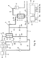
- FIG. 1 shows a schematic representation of the essential components a hemodialysis device.
- the dialysis machine has a dialyzer 1 on by a semipermeable membrane 2 in one of Dialysis fluid through which flows first chamber 3 and one of blood flowed through second chamber 4 is divided.
- the first chamber 3 is in one Dialysis fluid path 5 switched, the one Dialysis fluid supply line 6 and a dialysis fluid discharge line 7, while the second chamber 4 is switched into a blood path 8.
- the dialysis fluid supply line 6 of the dialysis fluid path 5 has a first line section 9 and a second line section 10.
- the first line section 9 connects a device 11 for provision of dialysis fluid with the inlet of a first chamber 12 through a germ-retaining membrane 13 into the first chamber 12 and one second chamber 14 divided sterile filter 15.
- the second supply section 10 connects the outlet of the second chamber 14 of the sterile filter 15 with the Inlet of the first chamber 3 of the dialyzer 1.
- the outlet of the first chamber 3 of the dialyzer 1 is connected to a via the dialysis fluid discharge line 7 Spout 16 connected.
- the first balancing chamber 17 of a balancing device 18 switched while the second chamber 19 of the balancing device in the Dialysis fluid discharge line 7 is switched.
- a dialysis fluid pump 20 switched.
- From the outlet of the first chamber 12 of the sterile filter 15 leads a first bypass line 21, into which a first bypass valve 22 is connected the dialysis fluid discharge line 7 upstream of the Dialysis fluid pump 20.
- Dialysis fluid supply line 6 Upstream of the dialyzer 1 is in the second line section 10 Dialysis fluid supply line 6 a first shut-off device 23 and downstream of the dialyzer is a second in the dialysis fluid discharge line 7 Shut-off device 24 arranged.
- a first device 27 for measuring the temperature and / or conductivity the dialysis fluid switched while in the Dialysis fluid discharge line 7 downstream of the first bypass line 21 second device 28 for measuring the temperature and / or conductivity of the Dialysis fluid is switched.
- the blood path 8 has a blood supply line 29 coming from the patient, which is connected to the input of the second chamber 4 of the dialyzer 1.
- the output of the second chamber 4 of the dialyzer leads through a Blood discharge line 30, into which a drip chamber 31 is connected, for Patient.
- the hemodialysis device has an ultrafiltration line 46 in which an ultrafiltration pump 45 is connected.
- the Ultrafiltration line 46 branches off from the dialysis fluid discharge line 7 upstream of the dialysis fluid pump 20 and opens into the Dialysis fluid discharge line downstream of the second chamber 19 of the Balance device 18.
- the device 32 for providing ready-to-use dialysis fluid has an evaluation device 33 and a control device 34.
- the Evaluation device 33 receives the measured values from first measuring device 27 via a data line 27a and the measured values of the second measuring device 28 via a data line 28a.
- the control device 34 is via a Data line 35 connected to the evaluation device 33 and controls the first and second shut-off device 23, 24 via the control lines 23a, 24a and that first and second bypass valves 22, 26 via the control lines 22a, 26a.
- the first and second shut-off devices 23, 24 opened and the first and second bypass valves 22, 26 closed, so that Dialysis fluid from the device 11 for providing the Dialysis fluid via the first chamber 17 of the balancing device 18 and the sterile filter 15 can flow into the first chamber 3 of the dialyzer.
- the dialysis fluid then flows over the first chamber of the dialyzer the second chamber 19 of the balancing device 18 to the outlet 16.
- the temperature and / or conductivity of the dialysis fluid is maintained during the dialysis treatment is continuously monitored with the first measuring device 27.
- a predetermined temperature and / or conductivity value compared. If the deviation is greater than a certain limit, the opens Controller 34 the first bypass valve 22 and closes the first and second shut-off device 23, 24. In principle, it is also sufficient if only a shut-off device is provided upstream of the dialyzer.
- the Dialysis fluid then flows via the first bypass line 21 directly to the Outlet 16, the dialyzer 1 from the dialysis fluid path is separated.
- the temperature and / or conductivity is now with the second measuring device 28 monitors.
- the evaluation device 33 the measured values of the second measuring device 28 with a predetermined one Temperature and / or conductivity value compared. If the deviation the control device 34 closes again the first bypass valve 22. Then the first and second Shut-off device 23, 24 are opened again, so that the dialyzer 1 again is flowed through by dialysis fluid.
- the The dialyzer is not immediately switched back into the dialysis fluid path.
- the Control device 34 opens after the first bypass valve 22 is closed first the second bypass valve 26, the first and second shut-off device 23, 24 remain closed.
- the in the second chamber 14 of the Sterile filter 15 located dialysis fluid can now be via the second Bypass line 25 bypassing dialyzer 1 to outlet 16 flow away.
- the temperature and / or conductivity of the dialysis fluid will either with the first or the second measuring device 27, 28 supervised.
- control device 34 closes the second bypass valve 26 and opens the first and second shut-off devices 23, 24. This ensures that only dialysis fluid can reach the dialyzer can, their temperature and / or conductivity a predetermined Temperature and / or conductivity value corresponds.
- Dialysis fluid via the second bypass line 25 is then particularly from Advantage if the first chamber of the sterile filter previously with dialysis fluid was flushed out to clog the membrane with germs or pyrogens to prevent. This avoids that during the The flushing process in the second chamber of the sterile filter has already cooled down Dialysis fluid has reached the dialyzer.
- Figure 1 b shows a further embodiment of the hemodialysis device. This differs from that described with reference to FIG. 1 Embodiment in that the first measuring device 27 is not downstream of the Sterile filter 15 in the second line section 10 of the Dialysis fluid supply line 6, but in the first line section 9 the dialysis fluid supply line 6 is arranged upstream of the sterile filter 15 is.
- the parts of the hemodialysis device according to Figure 1b, that of the The hemodialysis device according to FIG. 1a corresponds to the same Provide reference numerals.
- the monitoring takes place the temperature and / or conductivity of the through the first bypass line 21 flowing dialysis fluid with either the first or the second Measuring device 27, 28.
- dialysis fluid can only be used with the second measuring device 28 take place. Otherwise it works Hemodialysis device according to Figure 1b after the same program as the device of Figure 1 a, so that there is a further explanation superfluous.
- FIG. 2 shows a hemodiafiltration device in a schematic representation.
- the hemodiafiltration device differs from that below Referring to Figures 1a and 1b described hemodialysis device characterized in that in the second line section 10 of Dialysis fluid supply line 6 upstream of the first shut-off element 23 first chamber 36 of a second sterile filter 37 which is connected by a Germ-retaining membrane 38 into the first chamber 36 and a second Chamber 39 is divided.
- the second sterile filter 37 is a Substitute filter for obtaining substituate from the dialysis fluid during hemodiafiltration treatment.
- the second chamber 39 of the The substituate filter 37 is connected to the drip chamber 31 via a substituate line 40 connected.
- a substituate pump 41 is connected into the substituate line.
- Upstream of the substituate pump 41 is located in the substituate line 40 third shut-off device 42.
- From the substituate line 42 branches upstream of the third shut-off device 42 from a third bypass line 43, which is downstream of the second shut-off device 24 opens into the dialysis fluid discharge line 7.
- a third bypass valve 44 is connected in the third bypass line 43.
- the third shut-off device 42 and the third bypass valve 44 are further Control lines 42a, 44a controlled by the control device 34.
- the patient may Ultrafiltration line 46 by means of the ultrafiltration pump 45 liquid be withdrawn. Fluid withdrawn from the patient via the pump 45 is simultaneously via the substituate line 40 by means of the Substitute pump 41 fed back, the substituate liquid on-line is obtained from the dialysis fluid.
- the hemodiafiltration device not only has the advantage that the Dialyzer always dialysis fluid with the right temperature and / or Conductivity reached, but also that obtained from the dialysis fluid Substituate always has the right temperature.
- the first bypass line 21 prevents dialysis fluid with the wrong temperature and / or Conductivity the dialyzer or substituate with the wrong temperature Patient reached.
- the first bypass line is also used for flushing of the dialyzer.
- the second bypass line allows the parameters to be set after one Interruption e.g. after flushing, quickly back to the right ones Set values.
- the control device 34 shoots this third shut-off device 42 and opens the third bypass valve 44, so that Substitute from the second chamber 39 of the substituate filter 37 to the outlet 16 can drain.
- the Control device 34 again the third bypass valve 44 and opens the third Shut-off device 42 so that the patient can again use the substituate pump 41 Substituate can be supplied.
Abstract
Description
Die Erfindung betrifft ein Verfahren zur Bereitstellung betriebsbereiter Dialysieflüssigkeit in einer Vorrichtung zur extrakorporalen Blutbehandlung und eine Vorrichtung zur extrakorporalen Blutbehandlung mit einer Einrichtung zur Bereitstellung betriebsbereiter Dialysierflüssigkeit.The invention relates to a method for providing operationally ready Dialysis fluid in a device for extracorporeal blood treatment and a device for extracorporeal blood treatment with a Device for providing ready-to-use dialysis fluid.
Die Dialysierflüssigkeit wird üblicherweise on-line aus Frischwasser und einem Elektrolykonzentrat hergestellt, wobei letzteres eigensteril ist und Frischwasser üblicherweise keine Keime aufweist. Es ist jedoch nicht sichergestellt, daß die so hergestellte Dialysierflüssigkeit absolut steril ist. Die DE-A 36 41 843 beschreibt eine Hämodialysemaschine, in deren Dialysierflüssigkeitskreislauf stromauf der Dialysierflüssigkeitskammer des Dialysators ein Sterilfilter geschaltet ist, um dem Dialysator eine absolut sterile Dialysieiflüssigkeit bereitzustellen.The dialysis fluid is usually made on-line from fresh water and one Electrolyte concentrate produced, the latter being inherently sterile and fresh water usually has no germs. However, there is no guarantee that the the dialysis fluid thus produced is absolutely sterile. DE-A 36 41 843 describes a hemodialysis machine, in its dialysis fluid circuit a sterile filter upstream of the dialysis fluid chamber of the dialyzer is connected to the dialyzer an absolutely sterile dialysis fluid to provide.
Bei der Hämodiafiltration kann die Dialysierflüssigkeit on-line aus Frischwasser und einem Elektrolytkonzentrat und die Substitutionsflüssigkeit on-line aus der Dialysierflüssigkeit hergestellt werden. Das Elektrolytkonzentrat ist zwar in der Regel steril und das Frischwasser weist üblicherweise keine Keime auf, es ist jedoch nicht sichergestellt, daß die online hergestellte Dialysierflüssigkeit absolut steril und pyrogenfrei ist, weshalb die Dialysierflüssigkeit zur Herstellung der Substitutionsflüssigkeit in den absolut sterilen und pyrogenfreien Zustand überführt wird. Dazu wird stromauf des Dialysators Dialysierflüssigkeit entnommen, welche durch mindestens einen Filter geleitet wird, der durch eine Keime zurückhaltende hydrophile Membran in zwei Kammern geteilt ist. Eine derartige Vorrichtung mit zwei im Dialysierflüssigkeitssystem angeordneten Sterilfiltern ist beispielsweise aus der DE-A 34 44 671 und der EP-A 0 692 268 bekannt.In hemodiafiltration, the dialysis fluid can be removed online Fresh water and an electrolyte concentrate and the substitution liquid be made online from the dialysis fluid. The Electrolyte concentrate is usually sterile and the fresh water has Usually there are no germs, but there is no guarantee that online Dialysing liquid produced is absolutely sterile and pyrogen-free, which is why the dialysis fluid for the preparation of the substitution fluid in the absolutely sterile and pyrogen-free state is transferred. This is done upstream removed from the dialyzer dialysis fluid, which by at least a filter is passed through a germ-retaining hydrophilic Membrane is divided into two chambers. Such a device with two in Dialysis fluid system arranged sterile filters is for example from the DE-A 34 44 671 and EP-A 0 692 268 are known.
Um ein Zusetzen der Sterilfilter mit Keimen oder Pyrogenen zu verhindern, ist es bekannt, die Membran des Sterilfilters zeitweise mit Dialysierflüssigkeit freizuspülen.To prevent the sterile filter from becoming clogged with germs or pyrogens it is known to temporarily wash the membrane of the sterile filter with dialysis fluid rinse free.
Die EP-A-0 694 312 beschreibt eine Hämodiafiltrationsvorrichtung mit einem im Dialysierflüssigkeitsweg angeordneten Sterilfilter, dessen Membran über eine Leitung mit Dialysierflüssigkeit freigespült werden kann. Eine Bypassleitung verbindet die zum Dialysator führende Dialysierflüssigkeitszuführleitung mit der vom Dialysator zum Auslauf führenden Dialysierflüssigkeitsabführleitung.EP-A-0 694 312 describes a hemodiafiltration device with a Sterile filter arranged in the dialysis fluid path, the membrane of which a line can be flushed with dialysis fluid. A Bypass line connects the one leading to the dialyzer Dialysis fluid supply line with the from the dialyzer to the outlet leading dialysis fluid discharge line.
Bei den bekannten Blutbehandlungsvorrichtungen mit Sterilfiltern im Dialysierflüssigkeitsweg besteht die Gefahr, daß Dialysierflüssigkeit mit der falschen Temperatur oder Leitfähigkeit den Dialysator erreicht.In the known blood treatment devices with sterile filters in There is a risk of dialysis fluid path that dialysis fluid with the incorrect temperature or conductivity reached the dialyzer.
Während die erste Kammer des Sterilfilters beispielsweise mit Dialysierflüssigkeit durchspült wird, kommt es bei einer Unterbrechung der Behandlung zum Verweilen der Flüssigkeit in der zweiten Kammer des Filters. Nach Fortsetzung der Behandlung wird die dann ausgekühlte Flüssigkeit dem Dialysator zugeführt. Dialysieiflüssigkeit mit zu hoher Temperatur kann den Dialysator dann erreichen, wenn eine Störung in der Temperaturregelung der Einrichtung zur Bereitstellung von Dialysierflüssigkeit vorliegt.For example, while the first chamber of the sterile filter If dialysis fluid is flushed out, there is an interruption of the Treatment to hold the liquid in the second chamber of the filter. After the treatment is continued, the then cooled liquid becomes the Dialyzer fed. Dialysis fluid with too high a temperature can Reach the dialyzer if there is a fault in the temperature control of the Device for providing dialysis fluid is present.
Der Erfindung liegt die Aufgabe zugrunde, ein Verfahren zur Bereitstellung betriebsbereiter Dialysierflüssigkeit in einer Vorrichtung zur extrakorporalen Blutbehandlung anzugeben, das die Sicherheit der Blutbehandlung insofern erhöht, als den Dialysator auch nach dem Durchspülen des Sterilfilters Dialysierflüssigkeit mit einer vorgegebenen Temperatur oder Leitfähigkeit erreicht. Die Lösung dieser Aufgabe erfolgt erfindungsgemäß mit den im Patentanspruch 1 angegebenen Merkmalen.The invention is based on the object of providing a method operational dialysis fluid in a device for extracorporeal To specify blood treatment, the safety of blood treatment in this respect increased than the dialyzer even after rinsing the sterile filter Dialysis fluid with a given temperature or conductivity reached. This object is achieved with the im Claim 1 specified features.
Eine weitere Aufgabe der Erfindung liegt darin, eine Vorrichtung zur extrakorporalen Blutbehandlung zu schaffen, deren Sicherheit insofern erhöht ist, als den Dialysator auch nach dem Durchspülen des Sterilfilters Dialysierflüssigkeit mit einer vorgegebenen Temperatur oder Leitfähigkeit erreicht. Diese Aufgabe wird erfindungsgemäß mit den Merkmalen des Patentanspruchs 4 gelöst.Another object of the invention is to provide a device for to create extracorporeal blood treatment, the safety of which is increased as the dialyzer even after rinsing the sterile filter Dialysis fluid with a given temperature or conductivity reached. This object is achieved with the features of Claim 4 solved.
Bei dem erfindungsgemäßen Verfahren bzw. der erfindungsgemäßen Vorrichtung wird nach dem Schließen des ersten Bypassventils, wodurch der Spülvorgang der ersten Kammer des Sterilfilters unterbrochen wird, das zweite Bypassventil geöffnet, so daß die in der zweiten Kammer des Filters enthaltene Flüssigkeit, deren Temperatur und/oder Leitfähigkeit nicht einem vorgegebenen Wert entsprechen kann, über die zweite Bypassleitung in den Auslaß abgeführt wird. Dadurch wird vermieden, daß Dialysierflüssigkeit mit einer falschen Temperatur und/oder Zusammensetzung den Dialysator erreicht.In the method according to the invention or in the invention Device is closed after the first bypass valve, whereby the Flushing of the first chamber of the sterile filter is interrupted, the second Bypass valve opened so that the contained in the second chamber of the filter Liquid whose temperature and / or conductivity is not one can correspond to the specified value via the second bypass line in the Outlet is discharged. This avoids having dialysis fluid an incorrect temperature and / or composition reaches the dialyzer.
Wahrend die Dialysierflüssigkeit unter Umgehung des Dialysators zu dem Auslaß strömt, wird die Temperatur und/oder Leitfähigkeit der abfließenden Dialysierflüssigkeit überwacht. Wenn die Abweichung der gemessenen Leitfähigkeit und/oder Temperatur von einem vorgegebenen Leitfähigkeits- und/oder Temperaturwert einen bestimmten Grenzwert unterschreitet, wird die zweite Bypassleitung wieder unterbrochen. Den Dialysator erreicht nunmehr Dialysierflüssigkeit mit der richtigen Temperatur und/oder Leitfahigkeit.While the dialysis fluid bypasses the dialyzer to the Exhaust flows, the temperature and / or conductivity of the flowing Dialysis fluid monitored. If the deviation of the measured Conductivity and / or temperature from a given conductivity and / or Temperature value falls below a certain limit, the second bypass line interrupted again. Now reaches the dialyzer Dialysis fluid with the right temperature and / or conductivity.
Wenn das zweite Bypassventil geöffnet ist, ist der Strömungsweg durch die erste Kammer des Dialysators vorteilhafterweise unterbrochen. Die Unterbrechung des Strömungsweges erfolgt mit einem stromauf des Dialysators in der Dialysierflüssigkeitszuführleitung angeordneten Sperrorgan. When the second bypass valve is open, the flow path is through the first chamber of the dialyzer advantageously interrupted. The The flow path is interrupted with an upstream of the dialyzer blocking element arranged in the dialysis fluid supply line.
Vorzugsweise ist ein weiteres Sperrorgan stromab des Dialysators in der Dialysierflüssigkeitsabführleitung vorgesehen.A further blocking member is preferably located downstream of the dialyzer Dialysis fluid discharge line provided.
Die Leitfähigkeit und/oder Temperatur der Dialysierflüssigkeit kann mit einer stromab des Sterilfilters in Strömungsrichtung vor dem Dialysator angeordneten ersten Meßeinrichtung oder einer in der Dialysierflüssigkeitsabführleitung stromab der zweiten Bypassleitung angeordneten zweiten Meßeinrichtung erfolgen, wenn die Dialysierflüssigkeit über die zweite Bypassleitung zu dem Auslauf strömt.The conductivity and / or temperature of the dialysis fluid can be measured with a downstream of the sterile filter in the flow direction in front of the dialyzer arranged first measuring device or one in the Dialysis fluid discharge line downstream of the second bypass line arranged second measuring device take place when the dialysis fluid flows to the outlet via the second bypass line.
Um sicherzustellen, daß den Dialysator nur Dialysierflüssigkeit mit einer bestimmten Leitfahigkeit und/oder Temperatur erreicht, wird die Temperatur und/oder Leitfähigkeit der Dialysierflüssigkeit vonteilhafterweise mit einer stromauf des Sterilfilters in der Dialysierflüssigkeitszufühhrleitung angeordneten Meßeinrichtung überwacht. Wenn die Abweichung der gemessenen Temperatur und/oder Leitfähigkeit von einem vorgegebenen Temperatur- und/oder Leitfähigkeitswert einen bestimmten Grenzwert überschreitet, wird die erste Kammer des Sterilfilters über die erste Bypassleitung in den Durchfluß geschaltet und der zu dem Dialysator führende Teil des Dialysierflüssigkeitsweges wird unterbrochen. Die Leitfahigkeit und/oder Temperatur der Dialysierflüssigkeit wird nun mit der stromauf des Sterilfilters in der Dialysierflüssigkeitszuführleitung angeordneten Meßeinrichtung oder einer in der Dialysierflüssigkeitsabführleitung vorteilhafterweise stromab der ersten Bypassleitung angeordneten Meßeinrichtung überwacht. Wenn die Abweichung der Temperatur und/oder leitfähigkeit von einem vorgegebenen Leitfähigkeits- und/oder Temperaturwert einen bestimmten Grenzwert unterschreitet, wird die Bypassleitung unterbrochen, so daß die Dialysierflüssigkeit wieder durch den Sterilfilter strömt. Dadurch wird sichergestellt, daß den Dialysator nur Dialysierflüssigkeit mit einer bestimmten leitfähigkeit und/oder Temperatur erreicht. To ensure that the dialyzer only has dialysis fluid with a Certain conductivity and / or temperature is reached, the temperature and / or conductivity of the dialysis fluid, advantageously with a arranged upstream of the sterile filter in the dialysis fluid supply line Monitoring device monitors. If the deviation of the measured temperature and / or conductivity from a predetermined temperature and / or Conductivity value exceeds a certain limit, the first Chamber of the sterile filter via the first bypass line into the flow switched and the part of the dialyzer leading Dialysis fluid path is interrupted. The conductivity and / or The temperature of the dialysis fluid is now upstream of the sterile filter in the dialysis fluid supply line arranged measuring device or one in the dialysis fluid discharge line advantageously downstream of the first bypass line arranged measuring device monitors. If the Deviation of temperature and / or conductivity from a given one Conductivity and / or temperature value a certain limit falls below, the bypass line is interrupted so that the Dialysis fluid flows through the sterile filter again. This will ensured that the dialyzer only dialysis fluid with a certain conductivity and / or temperature reached.
Die Einhaltung genauer Temperatur- und/oder Leitfähigkeitswerte der Dialysierflüssigkeit ist insbesondere auch dann von Bedeutung, wenn aus der Dialysierflüssigkeit on-line Substituat gewonnen wird, das dem Patienten zugeführt wird.Compliance with exact temperature and / or conductivity values of the Dialysis fluid is also particularly important when from the Dialysis fluid is obtained on-line substituate that the patient is fed.
Im folgenden werden unter Bezugnahme auf die Zeichnungen mehrere Ausführungsbeispiele einer Vorrichtung zur extrakorporalen Blutbehandlung mit einer Einrichtung zur Bereitstellung betriebsbereiter Dialysierflüssigkeit naher erläutert.The following are several with reference to the drawings Embodiments of a device for extracorporeal blood treatment with a device for providing ready-to-use dialysis fluid explained in more detail.
Es zeigen:
- Figur 1a:
- eine Hämodialysevorrichtung mit einer Einrichtung zur Bereitstellung betriebsbereiter Dialysierflüssigkeit in schematischer Darstellung,
- Figur 1b:
- eine schematische Darstellung einer zweiten Ausführungsform der Hämodialysevorrichtung und
- Figur 2:
- eine Hämodiafiltrationsvorrichtung mit einer Einrichtung zur Bereitstellung betriebsbereiter Dialysierflüssigkeit in schematischer Darstellung.
- Figure 1a:
- a hemodialysis device with a device for providing ready-to-use dialysis fluid in a schematic representation,
- Figure 1b:
- a schematic representation of a second embodiment of the hemodialysis device and
- Figure 2:
- a hemodiafiltration device with a device for providing ready-to-use dialysis fluid in a schematic representation.
Figur 1 zeigt eine schematische Darstellung der wesentlichen Komponenten
einer Hämodialysevorrichtung. Die Dialysevorrichtung weist einen Dialysator
1 auf, der durch eine semipermeable Membran 2 in eine von
Dialysierflüssigkeit durchflossene erste Kammer 3 und eine von Blut
durchflossene zweite Kammer 4 geteilt ist. Die erste Kammer 3 ist in einen
Dialysierflüssigkeitsweg 5 geschaltet, der eine
Dialysierflüssigkeitszuführleitung 6 und eine Dialysierflüssigkeitsabführleitung
7 aufweist, wahrend die zweite Kammer 4 in einen Blutweg 8 geschaltet ist. Figure 1 shows a schematic representation of the essential components
a hemodialysis device. The dialysis machine has a dialyzer
1 on by a
Die Dialysierflüssigkeitszuführleitung 6 des Dialysierflüssigkeitsweges 5 weist
einen ersten Leitungsabschnitt 9 und einen zweiten Leitungsabschnitt 10 auf.
Der erste Leitungsabschnitt 9 verbindet eine Einrichtung 11 zur Bereitstellung
von Dialysierflüssigkelt mit dem Einlaß einer ersten Kammer 12 eines durch
eine Keime zurückhaltende Membran 13 in die erste Kammer 12 und eine
zweite Kammer 14 unterteilten Sterilfilters 15. Der zweite Zuleitungsabschnitt
10 verbindet den Auslaß der zweiten Kammer 14 des Sterilfilters 15 mit dem
Einlaß der ersten Kammer 3 des Dialysators 1. Der Auslaß der ersten Kammer
3 des Dialysators 1 ist über die Dialysierflüssigkeitsabführleitung 7 mit einem
Auslauf 16 verbunden.The dialysis
In den ersten Leitungsabschnitt 9 der Dialysierflüssigkeitszuführleitung 6 ist
die erste Bilanzierkammer 17 einer Bilanziereinrichtung 18 geschaltet, während
die zweite Kammer 19 der Bilanziereinrichtung in die
Dialysierflüssigkeitsabführleitung 7 geschaltet ist. Stromauf der zweiten
Kammer 19 der Bilanziereinrichtung 18 ist in die
Dialysierflüssigkeitsabführleitung 7 eine Dialysierflüssigkeitspumpe 20
geschaltet. Von dem Auslaß der ersten Kammer 12 des Sterilfilters 15 führt
eine erste Bypassleitung 21, in die ein erstes Bypassventil 22 geschaltet ist, zu
der Dialysierflüssigkeitsabführleitung 7 stromauf der
Dialysierflüssigkeitspumpe 20.In the
Stromauf des Dialysators 1 ist in dem zweiten Leitungsabschnitt 10 der
Dialysierflüssigkeitszuführleitung 6 ein erstes Absperrorgan 23 und stromab
des Dialysators ist in der Dialysierflüssigkeitsabführleitung 7 ein zweites
Absperrorgan 24 angeordnet. Eine zweite Bypassleitung 25, in die ein zweites
Bypassventil 26 geschaltet ist, verbindet den zweiten Leitungsabschnitt 10 der
Dialysierflüssigkeitszuführleitung 6 stromauf des ersten Absperrorgans 23 mit
der Dialysierflüssigkeitsabführleitung 7 stromab des zweiten Absperrorgans 24. Upstream of the dialyzer 1 is in the
In den zweiten Leitungsabschnitt 10 der Dialysierflüssigkeitszuführleitung 6 ist
eine erste Einrichtung 27 zum Messen der Temperatur und/oder Leitfähigkeit
der Dialysierflüssigkeit geschaltet, während in die
Dialysierflüssigkeitsabführleitung 7 stromab der ersten Bypassleitung 21 eine
zweite Einrichtung 28 zum Messen der Temperatur und/oder Leitfähigkeit der
Dialysierflüssigkeit geschaltet ist.In the
Der Blutweg 8 weist eine vom Patienten kommende Blutzuführleitung 29 auf,
die an den Eingang der zweiten Kammer 4 des Dialysators 1 angeschlossen ist.
Der Ausgang der zweiten Kammer 4 des Dialysators führt über eine
Blutabführleitung 30, in die eine Tropfkammer 31 geschaltet ist, zum
Patienten.The
Desweiteren weist die Hämodialysevorrichtung eine Ultrafiltrationsleitung 46
auf, in die eine Ultrafiltrationspumpe 45 geschaltet ist. Die
Ultrafiltrationsleitung 46 zweigt von der Dialysierflüssigkeitsabführleitung 7
stromauf der Dialysierflüssigkeitspumpe 20 ab und mündet in die
Dialysierflüssigkeitsabführleitung stromab der zweiten Kammer 19 der
Bilanziereinrichtung 18.Furthermore, the hemodialysis device has an
Die Einrichtung 32 zur Bereitstellung betriebsbereiter Dialysierflüssigkeit weist
eine Auswerteinrichtung 33 und eine Steuereinrichtung 34 auf. Die
Auswerteinrichtung 33 empfangt die Meßwerte der ersten Meßeinrichtung 27
über eine Datenleitung 27a und die Meßwerte der zweiten Meßeinrichtung 28
über eine Datenleitung 28a. Die Steuereinrichtung 34 ist über eine
Datenleitung 35 mit der Auswerteinrichtung 33 verbunden und steuert das erste
und zweite Absperrorgan 23, 24 über die Steuerleitungen 23a, 24a und das
erste und zweite Bypassventil 22, 26 über die Steuerleitungen 22a, 26a an.The
Während der Dialysebehandlung sind das erste und zweite Absperrorgan 23,
24 geöffnet und das erste und zweite Bypassventil 22, 26 geschlossen, so daß
Dialysierflüssigkeit aus der Einrichtung 11 zur Bereitstellung der
Dialysierflüssigkeit über die erste Kammer 17 der Bilanziereinrichtung 18 und
den Sterilfilter 15 in die erste Kammer 3 des Dialysators strömen kann. Aus
der ersten Kammer des Dialysators strömt die Dialysierflüssigkeit dann über
die zweite Kammer 19 der Bilanziereinrichtung 18 zu dem Auslauf 16.During the dialysis treatment, the first and second shut-off
Die Temperatur und/oder Leitfähigkeit der Dialysierflüssigkeit wird während
der Dialysebehandlung laufend mit der ersten Meßeinrichtung 27 überwacht. In
der Auswerteeinheit werden die Meßwerte der ersten Meßeinrichtung 27 mit
einem vorgegebenen Temperatur- und/oder Leitfähigkeitswert verglichen.
Wenn die Abweichung größer als ein bestimmter Grenzwert ist, öffnet die
Steuereinrichtung 34 das erste Bypassventil 22 und schließt das erste und
zweite Absperrorgan 23, 24. Prinzipiell ist es aber auch ausreichend, wenn nur
ein Absperrorgan stromauf des Dialysators vorgesehen ist. Die
Dialysierflüssigkeit strömt dann über die erste Bypassleitung 21 direkt zu dem
Auslauf 16, wobei der Dialysator 1 von dem Dialysierflüssigkeitsweg
abgetrennt ist. Die Temperatur und/oder Leitfähigkeit wird nun mit der
zweiten Meßeinrichtung 28 überwacht. In der Auswerteinrichtung 33 werden
die Meßwerte der zweiten Meßeinrichtung 28 mit einem vorgegebenen
Temperatur- und/oder Leitfähigkeitswert verglichen. Wenn die Abweichung
einen bestimmten Grenzwert unterschreitet, schließt die Steuereinrichtung 34
wieder das erste Bypassventil 22. Daraufhin können das erste und zweite
Absperrorgan 23, 24 wieder geöffnet werden, so daß der Dialysator 1 wieder
von Dialysierflüssigkeit durchströmt wird.The temperature and / or conductivity of the dialysis fluid is maintained during
the dialysis treatment is continuously monitored with the
Um aber zu verhindern, daß nach dem Schließen des ersten Bypassventils 22
Dialysierflüssigkeit aus der zweiten Kammer 14 des Sterilfilters 15 in den
Dialysator 1 strömt, deren Temperatur und/oder Leitfähigkeit nicht einem
vorgegebenen Temperatur- und/oder Leitfähigkeitswert entspricht, wird der
Dialysator nicht wieder sofort in den Dialysierflüssigkeitsweg geschaltet. Die
Steuereinrichtung 34 öffnet nach dem Schließen des ersten Bypassventils 22
zunächst das zweite Bypassventil 26, wobei das erste und zweite Absperrorgan
23, 24 weiterhin geschlossen bleiben. Die in der zweiten Kammer 14 des
Sterilfilters 15 befindliche Dialysierflüssigkeit kann nunmehr über die zweite
Bypassleitung 25 unter Umgehung des Dialysators 1 zu dem Auslauf 16
abfließen. Die Temperatur und/oder Leitfähigkeit der Dialysierflüssigkeit wird
dabei entweder mit der ersten oder der zweiten Meßeinrichtung 27, 28
überwacht. Erst wenn die Abweichung der Temperatur und/oder Leitfahigkeit
von einem vorgegebenen Temperatur- und/oder Leitfahigkeitswert einen
bestimmten Grenzwert unterschreitet, schließt die Steuereinrichtung 34 das
zweite Bypassventil 26 und öffnet das erste und zweite Absperrorgan 23, 24.
Dadurch wird erreicht, daß nur Dialysierflüssigkeit den Dialysator erreichen
kann, deren Temperatur und/oder Leitfähigkeit einem vorgegebenen
Temperatur- und/oder Leitfähigkeitswert entspricht.In order to prevent that after the
Das Abführen der in der zweiten Kammer 14 des Sterilfilters 15 befindlichen
Dialysierflüssigkeit über die zweite Bypassleitung 25 ist insbesondere dann von
Vorteil, wenn die erste Kammer des Sterilfilters zuvor mit Dialysierflüssigkeit
freigespült wurde, um ein Zusetzen der Membran mit Keimen oder Pyrogenen
zu verhindern. Dadurch wird vermieden, daß die während des
Freispülvorganges in der zweiten Kammer des Sterilfilters bereits abgekühlte
Dialysierflüssigkeit den Dialysator erreicht.The removal of those located in the
Figur 1 b zeigt eine weitere Ausführungsform der Hämodialysevorrichtung.
Diese unterscheidet sich von der unter Bezugnahme auf Figur 1 beschriebenen
Ausführungsform dadurch, daß die erste Meßeinrichtung 27 nicht stromab des
Sterilfilters 15 in dem zweiten Leitungsabschnitt 10 der
Dialysierflüssigkeitszuführleitung 6, sondern in dem ersten Leitungsabschnitt 9
der Dialysierflüssigkeitszuführleitung 6 stromauf des Sterilfilters 15 angeordnet
ist. Die Teile der Hämodialysevorrichtung gemäß Figur 1b, die denjenigen der
Hämodialysevorrichtung gemäß Figur 1a entsprechen, sind mit denselben
Bezugszeichen versehen. Bei dieser Ausführungsform erfolgt die Überwachung
der Temperatur und/oder Leitfähigkeit der durch die erste Bypassleitung 21
strömenden Dialysierflüssigkeit entweder mit der ersten oder der zweiten
Meßeinrichtung 27, 28. Die Überwachung der Temperatur und/oder
Leitfähigkeit der durch die zweite Bypassleitung 25 strömenden
Dialysierflüssigkeit kann bei dieser Ausführungsform allerdings nur mit der
zweiten Meßeinrichtung 28 erfolgen. Ansonsten arbeitet die
Hämodialysevorrichtung gemäß Figur 1b nach dem gleichen Programmablauf
wie die Vorrichtung gemäß Figur 1 a, so daß sich eine weitere Erläuterung
erübrigt.Figure 1 b shows a further embodiment of the hemodialysis device.
This differs from that described with reference to FIG. 1
Embodiment in that the
Figur 2 zeigt eine Hämodiafiltrationsvorrichtung in schematischer Darstellung.
Die Hämodiafiltrationsvorrichtung unterscheidet sich von der unter
Bezugnahme auf die Figuren 1a und 1b beschriebenen Hämodialysevorrichtung
dadurch, daß in den zweiten Leitungsabschnitt 10 der
Dialysierflüssigkeitszuführleitung 6 stromauf des ersten Absperrorgans 23 eine
erste Kammer 36 eines zweiten Sterilfilters 37 geschaltet ist, der durch eine
Keime zurückhaltende Membran 38 in die erste Kammer 36 und eine zweite
Kammer 39 geteilt ist. Bei dem zweiten Sterilfilter 37 handelt es sich um einen
Substituatfilter zur Gewinnung von Substituat aus der Dialysierflüssigkeit
während der Hämodiafiltrationsbehandlung. Die zweite Kammer 39 des
Substituatfilters 37 ist über eine Substituatleitung 40 mit der Tropfkammer 31
verbunden. In die Substituatleitung ist eine Substituatpumpe 41 geschaltet.Figure 2 shows a hemodiafiltration device in a schematic representation.
The hemodiafiltration device differs from that below
Referring to Figures 1a and 1b described hemodialysis device
characterized in that in the
Stromauf der Substituatpumpe 41 befindet sich in der Substituatleitung 40 ein
drittes Absperrorgan 42. Von der Substituatleitung 42 zweigt stromauf des
dritten Absperrorgans 42 eine dritte Bypassleitung 43 ab, die stromab des
zweiten Absperrorgans 24 in die Dialysierflüssigkeitsabführleitung 7 mündet.
In die dritte Bypassleitung 43 ist ein drittes Bypassventil 44 geschaltet. Das
dritte Absperrorgan 42 und das dritte Bypassventil 44 werden über weitere
Steuerleitungen 42a, 44a von der Steuereinrichtung 34 angesteuert. Upstream of the
Während der Blutbehandlung kann dem Patienten über die
Ultrafiltrationsleitung 46 mittels der Ultrafiltrationspumpe 45 Flüssigkeit
entzogen werden. Flüssigkeit, die dem Patienten über die Pumpe 45 entzogen
wird, wird gleichzeitig über die Substituatleitung 40 mittels der
Substituatpumpe 41 wieder zugeführt, wobei die Substituatflüssigkeit on-line
aus der Dialysierflüssigkeit gewonnen wird.During the blood treatment, the patient may
Ultrafiltration
Die Überwachung der Temperatur und/oder Leitfähigkeit der Dialysierflüssigkeit erfolgt bei der Hämodiafiltrationsvorrichtung nach dem gleichen Programmablauf wie bei der Hämodialysevorrichtung gemäß der Figuren 1a und 1b. Insofern erübrigt sich eine weitere Erläuterung.Monitoring the temperature and / or conductivity of the Dialysis fluid takes place in the hemodiafiltration device after same program sequence as with the hemodialysis device according to the Figures 1a and 1b. In this respect, no further explanation is necessary.
Die Hämodiafiltrationsvorrichtung hat nicht nur den Vorteil, daß den
Dialysator immer Dialysierflüssigkeit mit der richtigen Temperatur und/oder
Leitfähigkeit erreicht, sondern auch das aus der Dialysierflüssigkeit gewonnene
Substituat immer die richtige Temperatur hat. Mit der ersten Bypassleitung 21
wird verhindert, daß Dialysierflüssigkeit mit der falschen Temperatur und/oder
Leitfähigkeit den Dialysator bzw. Substituat mit der falschen Temperatur den
Patienten erreicht. Desweiteren dient die erste Bypassleitung zum Freispülen
des Dialysators. Die zweite Bypassleitung erlaubt es, die Parameter nach einer
Unterbrechung z.B. nach dem Freispülen, wieder schnell auf die richtigen
Werte einzustellen.The hemodiafiltration device not only has the advantage that the
Dialyzer always dialysis fluid with the right temperature and / or
Conductivity reached, but also that obtained from the dialysis fluid
Substituate always has the right temperature. With the
Zum Überprüfen des Substituatzweiges schießt die Steuereinrichtung 34 das
dritte Absperrorgan 42 und öffnet das dritte Bypassventil 44, so daß das
Substituat aus der zweiten Kammer 39 des Substituatfilters 37 zu dem Auslauf
16 abfließen kann. Sobald sich die richtigen Werte eingestellt haben, die mit
der zweiten Meßeinrichtung 28 überwacht werden, schließt die
Steuereinrichtung 34 wieder das dritte Bypassventil 44 und öffnet das dritte
Absperrorgan 42, so daß dem Patienten wieder mit der Substituatpumpe 41
Substituat zugeführt werden kann.To check the branch of substitute, the
Claims (6)
eine Einrichtung (32) zur Bereitstellung betriebsbereiter Dialysierflüssigkeit, die aufweist:
a device (32) for providing ready-to-use dialysis fluid, comprising:
Applications Claiming Priority (2)
| Application Number | Priority Date | Filing Date | Title |
|---|---|---|---|
| DE19801768 | 1998-01-19 | ||
| DE19801768A DE19801768C2 (en) | 1998-01-19 | 1998-01-19 | Method and device for providing operational dialysis fluid |
Publications (2)
| Publication Number | Publication Date |
|---|---|
| EP0930080A1 true EP0930080A1 (en) | 1999-07-21 |
| EP0930080B1 EP0930080B1 (en) | 2004-04-07 |
Family
ID=7855004
Family Applications (1)
| Application Number | Title | Priority Date | Filing Date |
|---|---|---|---|
| EP99100400A Expired - Lifetime EP0930080B1 (en) | 1998-01-19 | 1999-01-18 | Method for controlling a dialysis apparatus with a means for preparation of dialysate and device for this |
Country Status (5)
| Country | Link |
|---|---|
| US (1) | US6607697B1 (en) |
| EP (1) | EP0930080B1 (en) |
| JP (1) | JP4121652B2 (en) |
| DE (2) | DE19801768C2 (en) |
| ES (1) | ES2218882T3 (en) |
Cited By (8)
| Publication number | Priority date | Publication date | Assignee | Title |
|---|---|---|---|---|
| EP1348457A1 (en) * | 2002-03-19 | 2003-10-01 | Fresenius Medical Care Deutschland GmbH | Method of determining of a treatment parameter on a hemofiltration apparatus and hemodialysis apparatus therefor |
| DE10254099B3 (en) * | 2002-11-20 | 2004-03-11 | Mesys Gmbh Medizinische Systeme | Hemodialysing device, comprising mechanism for periodical rinsing working with pressure created by simultaneous closing of valves |
| EP1491222A1 (en) | 2003-06-25 | 2004-12-29 | Fresenius Medical Care Deutschland GmbH | Device for extracorporal blood treatment with equipment for checking a sterile filter and associated method |
| WO2013135379A1 (en) * | 2012-03-14 | 2013-09-19 | Fresenius Medical Care Deutschland Gmbh | Method for dosing a substituate generated by means of a blood treatment device, and devices |
| US8608680B2 (en) | 2010-02-09 | 2013-12-17 | Nikkiso Company Limited | Dialysis apparatus |
| WO2018041622A1 (en) * | 2016-08-27 | 2018-03-08 | Fresenius Medical Care Deutschland Gmbh | Blood treatment device and method for operating a blood treatment device |
| US10155082B2 (en) | 2002-04-10 | 2018-12-18 | Baxter International Inc. | Enhanced signal detection for access disconnection systems |
| EP3195888B1 (en) | 2014-09-19 | 2019-10-02 | Shibuya Corporation | Artificial dialysis device |
Families Citing this family (22)
| Publication number | Priority date | Publication date | Assignee | Title |
|---|---|---|---|---|
| US6916424B2 (en) | 2001-02-07 | 2005-07-12 | Nephros, Inc. | Method and apparatus for a hemodiafiltration delivery module |
| US7022098B2 (en) | 2002-04-10 | 2006-04-04 | Baxter International Inc. | Access disconnection systems and methods |
| US7052480B2 (en) | 2002-04-10 | 2006-05-30 | Baxter International Inc. | Access disconnection systems and methods |
| US20040254513A1 (en) | 2002-04-10 | 2004-12-16 | Sherwin Shang | Conductive polymer materials and applications thereof including monitoring and providing effective therapy |
| ATE434454T1 (en) * | 2003-01-07 | 2009-07-15 | Nxstage Medical Inc | BATCH FILTRATION SYSTEM FOR PRODUCING A STERILE REPLACEMENT LIQUID FOR KIDNEY TREATMENTS |
| US9700663B2 (en) | 2005-01-07 | 2017-07-11 | Nxstage Medical, Inc. | Filtration system for preparation of fluids for medical applications |
| US20080210606A1 (en) | 2004-01-07 | 2008-09-04 | Jeffrey Burbank | Filtration System Preparation of Fluids for Medical Applications |
| US8029454B2 (en) | 2003-11-05 | 2011-10-04 | Baxter International Inc. | High convection home hemodialysis/hemofiltration and sorbent system |
| US8287724B2 (en) * | 2007-07-05 | 2012-10-16 | Baxter International Inc. | Dialysis fluid measurement systems using conductive contacts |
| US8114276B2 (en) | 2007-10-24 | 2012-02-14 | Baxter International Inc. | Personal hemodialysis system |
| US8114043B2 (en) | 2008-07-25 | 2012-02-14 | Baxter International Inc. | Electromagnetic induction access disconnect sensor |
| US8753515B2 (en) | 2009-12-05 | 2014-06-17 | Home Dialysis Plus, Ltd. | Dialysis system with ultrafiltration control |
| US8501009B2 (en) | 2010-06-07 | 2013-08-06 | State Of Oregon Acting By And Through The State Board Of Higher Education On Behalf Of Oregon State University | Fluid purification system |
| WO2013052680A2 (en) | 2011-10-07 | 2013-04-11 | Home Dialysis Plus, Ltd. | Heat exchange fluid purification for dialysis system |
| US20130146541A1 (en) | 2011-12-13 | 2013-06-13 | Nxstage Medical, Inc. | Fluid purification methods, devices, and systems |
| JP6312118B2 (en) * | 2013-05-16 | 2018-04-18 | 学校法人東京理科大学 | Electric characteristic measuring apparatus, electric characteristic measuring method and program |
| US9731059B2 (en) * | 2013-07-02 | 2017-08-15 | Fresenius Medical Care Holdings, Inc. | Sensor and method of sensing for dialysis machine |
| ES2864727T3 (en) | 2014-04-29 | 2021-10-14 | Outset Medical Inc | Dialysis system and methods |
| US10518014B2 (en) * | 2015-10-30 | 2019-12-31 | Nxstage Medical, Inc. | Treatment fluid devices methods and systems |
| ES2908601T3 (en) | 2016-08-19 | 2022-05-03 | Outset Medical Inc | Peritoneal dialysis system and methods |
| DE102017001770B4 (en) | 2017-02-23 | 2023-06-22 | Fresenius Medical Care Deutschland Gmbh | Extracorporeal blood treatment device for operating an extracorporeal blood treatment device |
| WO2019072384A1 (en) * | 2017-10-11 | 2019-04-18 | Gambro Lundia Ab | Dialysis machines and methods of disinfecting a dialysis machine |
Citations (5)
| Publication number | Priority date | Publication date | Assignee | Title |
|---|---|---|---|---|
| DE3444671A1 (en) | 1984-12-07 | 1986-06-12 | Fresenius AG, 6380 Bad Homburg | HAEMODIA FILTRATION DEVICE |
| EP0265795A2 (en) * | 1986-10-30 | 1988-05-04 | Fresenius AG | Device for treating blood in an extracorporal circulatory system |
| DE3641843A1 (en) | 1986-12-08 | 1988-06-16 | Fresenius Ag | HAEMODIALYSIS DEVICE WITH STERILIZER |
| EP0692268A1 (en) | 1994-07-13 | 1996-01-17 | Fresenius AG | Preparation of substitution liquid in a haemo(dia)filtration apparatus |
| EP0694312A2 (en) | 1994-07-26 | 1996-01-31 | Hospal Industrie | Device and process for preparing a treatment fluid by filtration |
Family Cites Families (10)
| Publication number | Priority date | Publication date | Assignee | Title |
|---|---|---|---|---|
| DE444671C (en) | 1925-01-25 | 1927-05-28 | Vormals Skodawerke Ag | Two- or multi-stage steam jet air pump with intermediate condenser and water-cooled diffusers |
| EP0513421A1 (en) * | 1991-05-17 | 1992-11-19 | Fresenius AG | Device for measuring the volume of blood treated during haemodialysis |
| FR2680318B1 (en) * | 1991-08-14 | 1994-01-21 | Hospal Industrie | ARTIFICIAL KIDNEY AND ORDERING METHOD. |
| US5336165A (en) * | 1991-08-21 | 1994-08-09 | Twardowski Zbylut J | Artificial kidney for frequent (daily) Hemodialysis |
| FR2680976B1 (en) * | 1991-09-10 | 1998-12-31 | Hospal Ind | ARTIFICIAL KIDNEY PROVIDED WITH BLOOD CHARACTERISTIC MEANS OF DETERMINATION AND CORRESPONDING DETERMINATION METHOD. |
| FR2713937B1 (en) * | 1993-12-17 | 1996-05-31 | Hospal Ind | Method for determining a significant parameter of the progress of an extracorporeal blood treatment. |
| DE19534417A1 (en) * | 1995-09-16 | 1997-03-20 | Fresenius Ag | Method for checking at least one filter arranged in the dialysis fluid system of a device for extracorporeal blood treatment |
| FR2749761B1 (en) * | 1996-06-18 | 1998-07-31 | Hospal Ind | DISINFECTION PROCESS FOR A DIALYSIS MACHINE |
| DE19708391C1 (en) * | 1997-03-01 | 1998-10-22 | Fresenius Medical Care De Gmbh | Method and device for ultrafiltration in hemodialysis |
| DE19832451C1 (en) * | 1998-07-18 | 1999-08-26 | Fresenius Medical Care De Gmbh | Method of checking the orderly exchange of a used filter in an arrangement for extracorporal blood treatment |
-
1998
- 1998-01-19 DE DE19801768A patent/DE19801768C2/en not_active Expired - Fee Related
-
1999
- 1999-01-18 DE DE59909069T patent/DE59909069D1/en not_active Expired - Lifetime
- 1999-01-18 ES ES99100400T patent/ES2218882T3/en not_active Expired - Lifetime
- 1999-01-18 EP EP99100400A patent/EP0930080B1/en not_active Expired - Lifetime
- 1999-01-19 JP JP00996899A patent/JP4121652B2/en not_active Expired - Lifetime
- 1999-01-19 US US09/232,521 patent/US6607697B1/en not_active Expired - Lifetime
Patent Citations (5)
| Publication number | Priority date | Publication date | Assignee | Title |
|---|---|---|---|---|
| DE3444671A1 (en) | 1984-12-07 | 1986-06-12 | Fresenius AG, 6380 Bad Homburg | HAEMODIA FILTRATION DEVICE |
| EP0265795A2 (en) * | 1986-10-30 | 1988-05-04 | Fresenius AG | Device for treating blood in an extracorporal circulatory system |
| DE3641843A1 (en) | 1986-12-08 | 1988-06-16 | Fresenius Ag | HAEMODIALYSIS DEVICE WITH STERILIZER |
| EP0692268A1 (en) | 1994-07-13 | 1996-01-17 | Fresenius AG | Preparation of substitution liquid in a haemo(dia)filtration apparatus |
| EP0694312A2 (en) | 1994-07-26 | 1996-01-31 | Hospal Industrie | Device and process for preparing a treatment fluid by filtration |
Cited By (14)
| Publication number | Priority date | Publication date | Assignee | Title |
|---|---|---|---|---|
| US6939471B2 (en) | 2002-03-19 | 2005-09-06 | Fresenius Medical Care Deutschland Gmbh | Method for determining a treatment parameter on a haemofiltration device, and haemofiltration device for applying the method |
| DE10212247C1 (en) * | 2002-03-19 | 2003-12-18 | Fresenius Medical Care De Gmbh | Method for determining a treatment parameter on a hemofiltration device and hemofiltration device for using the method |
| EP1348457A1 (en) * | 2002-03-19 | 2003-10-01 | Fresenius Medical Care Deutschland GmbH | Method of determining of a treatment parameter on a hemofiltration apparatus and hemodialysis apparatus therefor |
| US10155082B2 (en) | 2002-04-10 | 2018-12-18 | Baxter International Inc. | Enhanced signal detection for access disconnection systems |
| WO2004045678A1 (en) * | 2002-11-20 | 2004-06-03 | Mesys Gmbh | Haemodialysis unit |
| DE10254099B3 (en) * | 2002-11-20 | 2004-03-11 | Mesys Gmbh Medizinische Systeme | Hemodialysing device, comprising mechanism for periodical rinsing working with pressure created by simultaneous closing of valves |
| DE10328435B3 (en) * | 2003-06-25 | 2005-03-24 | Fresenius Medical Care Deutschland Gmbh | Device for extracorporeal blood treatment with a device for checking a sterile filter and method for checking a sterile filter of an extracorporeal blood treatment device |
| EP1491222A1 (en) | 2003-06-25 | 2004-12-29 | Fresenius Medical Care Deutschland GmbH | Device for extracorporal blood treatment with equipment for checking a sterile filter and associated method |
| US8182691B2 (en) | 2003-06-25 | 2012-05-22 | Fresenius Medical Care Deutschland Gmbh | Apparatus for extracorporeal blood treatment with a device for checking a sterile filter, and method of checking a sterile filter of an extracorporeal blood treatment apparatus |
| US8608680B2 (en) | 2010-02-09 | 2013-12-17 | Nikkiso Company Limited | Dialysis apparatus |
| WO2013135379A1 (en) * | 2012-03-14 | 2013-09-19 | Fresenius Medical Care Deutschland Gmbh | Method for dosing a substituate generated by means of a blood treatment device, and devices |
| US11154645B2 (en) | 2012-03-14 | 2021-10-26 | Fresenius Medical Care Deutschland Gmbh | Producing and dosing a substituate during blood treatment |
| EP3195888B1 (en) | 2014-09-19 | 2019-10-02 | Shibuya Corporation | Artificial dialysis device |
| WO2018041622A1 (en) * | 2016-08-27 | 2018-03-08 | Fresenius Medical Care Deutschland Gmbh | Blood treatment device and method for operating a blood treatment device |
Also Published As
| Publication number | Publication date |
|---|---|
| US6607697B1 (en) | 2003-08-19 |
| JP4121652B2 (en) | 2008-07-23 |
| DE59909069D1 (en) | 2004-05-13 |
| DE19801768C2 (en) | 2001-04-19 |
| EP0930080B1 (en) | 2004-04-07 |
| JPH11267197A (en) | 1999-10-05 |
| ES2218882T3 (en) | 2004-11-16 |
| DE19801768A1 (en) | 1999-07-29 |
Similar Documents
| Publication | Publication Date | Title |
|---|---|---|
| EP0930080B1 (en) | Method for controlling a dialysis apparatus with a means for preparation of dialysate and device for this | |
| EP0692268B1 (en) | Preparation of substitution liquid in a haemofiltration apparatus or haemodiafiltration apparatus | |
| EP0692269B1 (en) | Haemo(dia)filtration device with filtrate flow control | |
| DE69827338T2 (en) | Device for monitoring an infusion pump | |
| DE69532258T2 (en) | Device and method for preparing a treatment liquid by filtration | |
| EP0763367B1 (en) | Method for testing at least one filter mounted in a dialyse circuit | |
| DE19708391C1 (en) | Method and device for ultrafiltration in hemodialysis | |
| DE102006050272B4 (en) | Hemodialysis machine, hemodiafiltration device, method of sampling such devices, and sampling set for use with such devices and methods | |
| DE3641843C2 (en) | ||
| DE10212247C1 (en) | Method for determining a treatment parameter on a hemofiltration device and hemofiltration device for using the method | |
| DE3416955C2 (en) | Hemodialysis machine | |
| DE3442744C2 (en) | ||
| DE19940624C1 (en) | Safety device for extracorporal blood dialysis or filtering device compares detected trans membrane pressure with dynamically adapted pressure range for operation of alarm device | |
| DE19607162C2 (en) | Use of a two module dialyzer to perform a method of filtering and immediately using substituate fluid in a hemodial filtration device | |
| EP1491222B1 (en) | Device for extracorporal blood treatment with equipment for checking a sterile filter and associated method | |
| EP0898974A2 (en) | Blood treatment apparatus including a device to determine hemodialysis parameters and a method for their determination | |
| DE10218846C1 (en) | Interruption or variation of flowrate during extracorporeal blood treatment, reduces delivery rate of substitute pump and ultrafiltration rate in controlled manner | |
| DE60030460T2 (en) | DEVICE FOR EXTRACORPORAL BLOOD CLEANING | |
| EP1029554B1 (en) | Apparatus for dialysis treatment | |
| EP3955988B1 (en) | Recirculation measurement by means of diffusion equilibrium | |
| DE3744849C2 (en) | ||
| DE102006060611A1 (en) | Arrangement for connecting a medical device to a water pipe | |
| EP0513672B1 (en) | Blood treatment device with volume balanced flow | |
| DE3448262C2 (en) | Method of testing sterilising filters of a haemodial filtration apparatus | |
| DE10245619A1 (en) | Blood return method for use with a dialysis machine in which the occurrence of a substitute liquid in the return line is precisely detected so that the volume of blood remaining in the line can be accurately returned |
Legal Events
| Date | Code | Title | Description |
|---|---|---|---|
| PUAI | Public reference made under article 153(3) epc to a published international application that has entered the european phase |
Free format text: ORIGINAL CODE: 0009012 |
|
| AK | Designated contracting states |
Kind code of ref document: A1 Designated state(s): DE ES FR GB IT |
|
| AX | Request for extension of the european patent |
Free format text: AL;LT;LV;MK;RO;SI |
|
| RAP1 | Party data changed (applicant data changed or rights of an application transferred) |
Owner name: FRESENIUS MEDICAL CARE DEUTSCHLAND GMBH |
|
| 17P | Request for examination filed |
Effective date: 19990925 |
|
| AKX | Designation fees paid |
Free format text: DE ES FR GB IT |
|
| 17Q | First examination report despatched |
Effective date: 20030213 |
|
| GRAP | Despatch of communication of intention to grant a patent |
Free format text: ORIGINAL CODE: EPIDOSNIGR1 |
|
| RTI1 | Title (correction) |
Free format text: METHOD FOR CONTROLLING A DIALYSIS APPARATUS WITH A MEANS FOR PREPARATION OF DIALYSATE AND DEVICE FOR THIS |
|
| GRAS | Grant fee paid |
Free format text: ORIGINAL CODE: EPIDOSNIGR3 |
|
| GRAA | (expected) grant |
Free format text: ORIGINAL CODE: 0009210 |
|
| AK | Designated contracting states |
Kind code of ref document: B1 Designated state(s): DE ES FR GB IT |
|
| REG | Reference to a national code |
Ref country code: GB Ref legal event code: FG4D Free format text: NOT ENGLISH |
|
| REF | Corresponds to: |
Ref document number: 59909069 Country of ref document: DE Date of ref document: 20040513 Kind code of ref document: P |
|
| GBT | Gb: translation of ep patent filed (gb section 77(6)(a)/1977) |
Effective date: 20040603 |
|
| REG | Reference to a national code |
Ref country code: ES Ref legal event code: FG2A Ref document number: 2218882 Country of ref document: ES Kind code of ref document: T3 |
|
| ET | Fr: translation filed | ||
| PLBE | No opposition filed within time limit |
Free format text: ORIGINAL CODE: 0009261 |
|
| STAA | Information on the status of an ep patent application or granted ep patent |
Free format text: STATUS: NO OPPOSITION FILED WITHIN TIME LIMIT |
|
| 26N | No opposition filed |
Effective date: 20050110 |
|
| REG | Reference to a national code |
Ref country code: DE Ref legal event code: R082 Ref document number: 59909069 Country of ref document: DE Representative=s name: OANDO OPPERMANN & OPPERMANN LLP, DE Ref country code: DE Ref legal event code: R082 Ref document number: 59909069 Country of ref document: DE Representative=s name: MAI, OPPERMANN & PARTNER I. L., DE |
|
| REG | Reference to a national code |
Ref country code: DE Ref legal event code: R082 Ref document number: 59909069 Country of ref document: DE Representative=s name: OANDO OPPERMANN & OPPERMANN LLP, DE |
|
| REG | Reference to a national code |
Ref country code: FR Ref legal event code: PLFP Year of fee payment: 18 |
|
| REG | Reference to a national code |
Ref country code: FR Ref legal event code: PLFP Year of fee payment: 19 |
|
| REG | Reference to a national code |
Ref country code: FR Ref legal event code: PLFP Year of fee payment: 20 |
|
| PGFP | Annual fee paid to national office [announced via postgrant information from national office to epo] |
Ref country code: FR Payment date: 20171221 Year of fee payment: 20 |
|
| PGFP | Annual fee paid to national office [announced via postgrant information from national office to epo] |
Ref country code: GB Payment date: 20171222 Year of fee payment: 20 |
|
| PGFP | Annual fee paid to national office [announced via postgrant information from national office to epo] |
Ref country code: ES Payment date: 20180201 Year of fee payment: 20 Ref country code: DE Payment date: 20171218 Year of fee payment: 20 |
|
| PGFP | Annual fee paid to national office [announced via postgrant information from national office to epo] |
Ref country code: IT Payment date: 20180102 Year of fee payment: 20 |
|
| REG | Reference to a national code |
Ref country code: DE Ref legal event code: R071 Ref document number: 59909069 Country of ref document: DE |
|
| REG | Reference to a national code |
Ref country code: GB Ref legal event code: PE20 Expiry date: 20190117 |
|
| PG25 | Lapsed in a contracting state [announced via postgrant information from national office to epo] |
Ref country code: GB Free format text: LAPSE BECAUSE OF EXPIRATION OF PROTECTION Effective date: 20190117 |
|
| REG | Reference to a national code |
Ref country code: ES Ref legal event code: FD2A Effective date: 20200723 |
|
| PG25 | Lapsed in a contracting state [announced via postgrant information from national office to epo] |
Ref country code: ES Free format text: LAPSE BECAUSE OF EXPIRATION OF PROTECTION Effective date: 20190119 |