EP0930810A1 - Plasma torch with adjustable distributor and gas analysis system using such a torch - Google Patents
Plasma torch with adjustable distributor and gas analysis system using such a torch Download PDFInfo
- Publication number
- EP0930810A1 EP0930810A1 EP98402992A EP98402992A EP0930810A1 EP 0930810 A1 EP0930810 A1 EP 0930810A1 EP 98402992 A EP98402992 A EP 98402992A EP 98402992 A EP98402992 A EP 98402992A EP 0930810 A1 EP0930810 A1 EP 0930810A1
- Authority
- EP
- European Patent Office
- Prior art keywords
- gas
- plasma
- tube
- injector
- torch
- Prior art date
- Legal status (The legal status is an assumption and is not a legal conclusion. Google has not performed a legal analysis and makes no representation as to the accuracy of the status listed.)
- Withdrawn
Links
Images


Classifications
-
- H—ELECTRICITY
- H05—ELECTRIC TECHNIQUES NOT OTHERWISE PROVIDED FOR
- H05H—PLASMA TECHNIQUE; PRODUCTION OF ACCELERATED ELECTRICALLY-CHARGED PARTICLES OR OF NEUTRONS; PRODUCTION OR ACCELERATION OF NEUTRAL MOLECULAR OR ATOMIC BEAMS
- H05H1/00—Generating plasma; Handling plasma
- H05H1/24—Generating plasma
- H05H1/26—Plasma torches
- H05H1/30—Plasma torches using applied electromagnetic fields, e.g. high frequency or microwave energy
Definitions
- the present invention relates to a torch with plasma, intended for the excitation of a gas with a view to its analysis.
- the invention also relates to an installation analysis of a gas using such a plasma torch.
- gas analysis techniques are indirect techniques, such as filtration, hydrolysis or bubbling, according to which the impurities with which it is to determine the concentration are extracted from the gas before analysis.
- the technique of analysis by filtration uses a gas filtration membrane to analyze in order to retain the impurities it contains. These the latter are then dissolved in an acid solution, then analyzed, for example by spectrometry, with a view to determine the nature and concentration.
- a gas sample to be analyzed is introduced into a thermal source, such as a plasma, capable of dissociating chemical species into free atoms present in the sample and then to excite and possibly to ionize the atoms obtained. These atoms excited are then detected from the measurement of different wavelengths they emit, or, if they are ionized, from the measurement of their mass.
- a thermal source such as a plasma
- the gas passing through this zone device experiences less excitation, which contributes to degrade the accuracy of the measurement.
- the object of the invention is to overcome the drawbacks cited above.
- a plasma torch for the excitation of a gas for analysis comprising an injector configured as a main tube intended to be connected to a gas supply source at analyze, and an external cylindrical double-walled sleeve, coaxial with the injector, and delimiting between its walls consecutive internal and external annular canal cylindrical supply of a plasma gas intended for be connected to a corresponding power source in view of the production of a plasma at the outlet of said sleeve, is characterized in that said injector is of diameter variable.
- the invention also relates to an installation gas analysis, characterized in that it comprises a plasma torch as defined above, connected to a gas supply source to be analyzed, to a source supply of plasma gas and advantageously also to a source of gas to guide the gas to be analyzed in the plasma generated at the outlet of the torch in the gas plasma, and optical detection means capable of measure the light intensity emitted by impurities present in the plasma, connected to a processing unit comprising means for calculating the concentration of impurities from the light intensity value measured and at least one predetermined reference value, stored in a memory associated with said unit of treatment, and obtained by prior calibration.
- a plasma torch is shown intended to dissociate the chemical species from a gas including impurities, to generate free atoms and excite the atoms thus obtained for the purpose of determining of the impurity concentration.
- the gas to be analyzed consists of a gas used in the field of semiconductor manufacturing, such as halogen or fluorinated gas, and the impurities are formed by metallic elements such than nickel, iron, manganese ...
- the plasma torch designated by the general numerical reference 10 includes: a central injector 12 configured in the form of a tube, a external cylindrical sleeve 14 with double wall (28/30) and a winding 16 connected to a high current source frequency 18.
- the wall 20 of the injector internally defines a channel 26 intended to be connected to a power source torch 10 into a gas to be analyzed (not shown in this figure).
- the sleeve 14 has an inner wall 28 and an outer wall 30 which extends beyond the free end of the inner wall 28.
- These walls are made of a material suitable for the intended use, i.e. capable of withstanding high temperatures, for example silica glass.
- the internal and external walls of the sleeve 14 delimit between them a cylindrical annular channel 32 connected, in operation, to a gas supply source plasmagen, e.g. Argon, for production of a plasma at the outlet of the sleeve.
- a gas supply source plasmagen e.g. Argon
- the consecutive external wall 30 of the sleeve forms the external wall of the torch 10 and is equipped, in the vicinity of its end edge, of the winding 16.
- the latter is connected to the current source high frequency, conventional type, capable of delivering to the winding a current at a frequency between 5 MHz and 100 MHz.
- the winding Under the action of the current source 18, the winding generates, as is conventional, an electromagnetic field radially decreasing towards the axis XX 'of the torch 10.
- Plasma gas supplied through the channel annular 32, at a flow rate for example of 20 liters / minute, is delivered in an area where the value of the electromagnetic field is substantially maximum. The latter creates a plasma in the plasma gas by acceleration of its charged particles.
- the plasma shows movements of recirculation under the effect of Lorentz forces applying to charged particles.
- the gas velocity is negative in the axial zone, that is to say that the particles are animated by a movement directed upstream of the torch, considering the direction gas flow, which opposes the introduction of gas to analyze.
- the gas to be analyzed is introduced into the internal supply channel 26 according to the direction represented by arrow F2 in the axial zone, at a rate commonly of the order of a few ml / minute at a few hundred ml / minute.
- a detector photoelectric 34 is connected to a processing unit 36 calculating the concentration of impurities in gas from the wavelength value of the radiation emitted by particles of excited impurities, as will be described in detail later.
- FIG. 2 shows an embodiment of the variable diameter injector according to the invention.
- the injector 12 is here formed of two coaxial tubes external (20) and internal (90), the internal tube 90 being suitable to slide vertically inside the outer tube.
- This sliding effect is, for the embodiment shown here, obtained by pneumatic control 91, acting on a micro-cylinder 92.
- This internal tube driven by the micro-cylinder according to the mechanism which has just been described, can therefore slide vertically inside the outer tube 20.
- Lowering the upper end of the inner tube relative to the upper end of the outer tube may typically be of the order of 1 to 2 cm.
- the torch here comprises a central injector 12 a little particular which comprises, in accordance with one of the modes advantageous implementation of the invention previously mentioned, an additional external tube 22, coaxial with the tube main 20, and thus delimiting two coaxial channels internal and external respectively for one to the supply of gas to the torch to be analyzed and the other to supplying the torch with a guide gas for said gas at analyze in plasma.
- the guide gas is delivered at a flow rate for example of the order of a few hundred ml / minute, and ensures therefore guiding the gas to be analyzed in the plasma P. This guidance thus opposes the action of Lorentz forces on the gas to be analyzed by helping to prevent the gas from analyze is deflected (i.e. ensuring that the whole of the sample reaches the plasma).
- the gas guide whose composition is perfectly controlled, being driven towards the periphery of the torch instead of gas to be analyzed, deposits on the wall are thus avoided external 30, particles forming part of the gas to be analyzed, choosing the guide gas so appropriate.
- the guide gas comprises helium or argon or a mixture of such gases.
- the injection of a gas of guidance inside the injector is optional.
- a simple tube 20 for injecting the gas to be analyzed without for example representing the presence an internal tube 90 coaxial with the external tube 20, and being able slide inside this outer tube 20 (mode of Figure 2).
- the installation includes a plasma torch 54 according to the invention, for example similar to the torch described in the context of FIGS. 1 and 2, associated with a high frequency current generator 56, and at a photodetector 58 itself connected to a processing unit 60.
- cylindrical sleeve torch 54 external is supplied with Argon (Ar) for create a plasma preferably at atmospheric pressure or slight depression.
- the injector 62 intended to allow the introduction into the plasma of the gas to be analyzed is connected to a first mixer 64 comprising a first input 66 supplied with an inert gas, such as Argon, allowing to increase the gas drive speed to analyze, and a second input 68 connected to the output a second mixer 70.
- a first mixer 64 comprising a first input 66 supplied with an inert gas, such as Argon, allowing to increase the gas drive speed to analyze, and a second input 68 connected to the output a second mixer 70.
- Unit 76 has an entrance for admission aerosols from unit 78.
- Unit 78 also has a gas inlet 86 allowing the admission of an inert gas such as argon.
- the elements to be dosed at a known concentration and in a given form (liquid, solid or gaseous) closest to that of elements to be determined in the gas samples G.
- the polluting elements can be in the form solid or gaseous, and more rarely liquid.
- solid particles often present in chemical gases are less than one micron in size. For such a dimension, these small particles are rapidly volatilized and generate in an Argon plasma a light intensity identical to that generated by gaseous compounds.
- gas 86 for example argon transports this aerosol to the desolvation unit.
- the standard samples thus created are trained in plasma P by a gas similar to gas G, but lacking impurity, or by Argon.
- the light intensity emitted by the impurities is detected by photodetector 58 (monochromator and / or polychromator) then stored in a memory 84 of the unit analysis 60.
- the gas G is presented at the input of mixer 70 and is injected into the plasma P.
- the light intensity emitted by the impurities of gas G is then presented at the input of the analysis unit 60.
- the latter includes means of calculation of the type classic, ensuring the comparison between the intensity light detected impurities to be measured and the values of reference previously obtained and stored in the memory 84.
- the exact concentration of particles in the gas G is thus for example obtained by identification of the sample whose corresponding signal has a wavelength and intensity identical to the values measured from gas G.
- Figure 6 represents a schematic view in axial section of a torch plasma according to the invention, incorporating at the level of sleeve an intermediate tube.
- the torch shown in Figure 6 indeed has a tube intermediate 40, coaxial with the sleeve 42, located between the outer and inner walls of the sleeve (42A and 42B), the tube intermediate 40 and the outer wall 42A of the sleeve delimiting a gas supply channel 45 protection of the external wall (42A) of the torch against solid deposits.
- the torch shown in Figure 6 is provided with a winding 46 supplied by a current source at high frequency 48 and placed in the vicinity of the unit end of the torch, and a photodetector 50 connected to a processing unit 52.
- the supply channel 45 is therefore connected to a shielding gas supply source (not shown) able to react with species likely to deposit on the internal surface of the external wall 42A of the torch to form a volatile compound.
- the gas to be analyzed comprises silane (SiH 4 )
- the shielding gas comprises chlorine, possibly mixed with argon, reacting with silicon to form SiCL 4 .
- the latter compound is a volatile species, any deposit based on silicon is thus avoided.
- the torch here comprises a central injector 38 a double-walled (38A, 38B) for injecting part of the gas to analyze and on the other hand a "guide" gas.
Landscapes
- Physics & Mathematics (AREA)
- Engineering & Computer Science (AREA)
- Plasma & Fusion (AREA)
- Electromagnetism (AREA)
- Spectroscopy & Molecular Physics (AREA)
- Investigating, Analyzing Materials By Fluorescence Or Luminescence (AREA)
- Other Investigation Or Analysis Of Materials By Electrical Means (AREA)
- Plasma Technology (AREA)
Abstract
Description
La présente invention est relative à une torche à plasma, destinée à l'excitation d'un gaz en vue de son analyse.The present invention relates to a torch with plasma, intended for the excitation of a gas with a view to its analysis.
L'invention se rapporte également à une installation d'analyse d'un gaz utilisant une telle torche à plasma.The invention also relates to an installation analysis of a gas using such a plasma torch.
Actuellement, les techniques d'analyse des gaz sont des techniques indirectes, telles que la filtration, l'hydrolyse ou le barbotage, selon lesquelles les impuretés dont il s'agit de déterminer la concentration sont extraites du gaz avant analyse.Currently, gas analysis techniques are indirect techniques, such as filtration, hydrolysis or bubbling, according to which the impurities with which it is to determine the concentration are extracted from the gas before analysis.
Ainsi, par exemple, la technique d'analyse par filtration utilise une membrane de filtration du gaz à analyser en vue de retenir les impuretés qu'il contient. Ces dernières sont ensuite dissoutes dans une solution acide, puis analysées, par exemple par spectrométrie, en vue d'en déterminer la nature et la concentration.So, for example, the technique of analysis by filtration uses a gas filtration membrane to analyze in order to retain the impurities it contains. These the latter are then dissolved in an acid solution, then analyzed, for example by spectrometry, with a view to determine the nature and concentration.
Ces techniques conventionnelles d'analyse présentent un certain nombre d'inconvénients.These conventional analysis techniques present a a number of drawbacks.
Tout d'abord, en raison de leur nature, et en particulier de la présence d'une étape d'extraction des particules à analyser, ces techniques ne sont pas adaptées pour permettre une analyse en continu de la qualité d'un gaz.First of all, due to their nature, and in particular of the presence of a stage of extraction of particles to be analyzed, these techniques are not suitable to allow continuous analysis of the quality of a gas.
En outre, elles fournissent des résultats relativement imprécis. En effet, ces techniques permettent seulement d'obtenir une valeur de concentration moyenne correspondant au montant total du prélèvement. Elles ne permettent donc pas la détection de variations instantanées des concentrations.In addition, they provide relatively imprecise. Indeed, these techniques only allow to obtain a corresponding average concentration value the total amount of the levy. They therefore do not allow not detecting instantaneous variations in concentrations.
De surcroít, certaines particules d'impuretés sont susceptibles de se présenter sous la forme de composés volatiles qui ne peuvent être extraits du gaz à l'aide de telles techniques. Le résultat fourni est ainsi susceptible d'être sous-estimé.In addition, certain particles of impurities are likely to be in the form of compounds volatiles that cannot be removed from the gas using such techniques. The result provided is thus likely to be underestimated.
Enfin, ces techniques engendrent un risque non négligeable de contamination du gaz et nécessitent un équipement relativement complexe.Finally, these techniques generate a risk not negligible gas contamination and require a relatively complex equipment.
On a tenté de palier ces inconvénients en utilisant une technique d'analyse directe des gaz. We tried to overcome these drawbacks by using a direct gas analysis technique.
Selon cette technique, un échantillon gazeux à analyser est introduit dans une source thermique, tel qu'un plasma, capable de dissocier en atomes libres les espèces chimiques présentes dans l'échantillon, puis d'exciter et éventuellement d'ioniser les atomes obtenus. Ces atomes excités sont ensuite détectés à partir de la mesure des différentes longueurs d'ondes qu'ils émettent, ou, s'ils sont ionisés, à partir de la mesure de leur masse.According to this technique, a gas sample to be analyzed is introduced into a thermal source, such as a plasma, capable of dissociating chemical species into free atoms present in the sample and then to excite and possibly to ionize the atoms obtained. These atoms excited are then detected from the measurement of different wavelengths they emit, or, if they are ionized, from the measurement of their mass.
Bien que cette technique permette l'analyse en continu d'un gaz, elle présente également un certain nombre d'inconvénients, notamment en raison des mouvements de recirculation de gaz engendrés sous l'action de forces de LORENTZ au voisinage de l'inducteur utilisé pour générer le plasma.Although this technique allows continuous analysis of a gas it also has a number disadvantages, in particular due to the movements of recirculation of gases generated by the action of LORENTZ in the vicinity of the inductor used to generate the plasma.
Ces mouvements de recirculation vont entraíner le gaz vers la périphérie du plasma et provoquer le dépôt des produits de décomposition sur la torche et donc une pollution néfaste de celle-ci gênant la détection optique, ainsi qu'une modification du transfert d'énergie entre la bobine d'induction et le plasma.These recirculation movements will entrain the gas towards the periphery of the plasma and cause the deposition of decomposition products on the torch and therefore a harmful pollution of this interfering with optical detection, as well as a modification of the energy transfer between the induction coil and plasma.
Par ailleurs, le gaz passant dans cette zone périphérique subit une excitation moindre, ce qui contribue à dégrader la précision de la mesure.Furthermore, the gas passing through this zone device experiences less excitation, which contributes to degrade the accuracy of the measurement.
Les travaux menés à bien par la Demanderesse sur ce sujet ont par ailleurs démontré que selon la nature du gaz à analyser (par exemple selon sa nature diatomique ou non), on observe un risque important de soufflage du plasma lors de l'introduction du gaz à analyser dans ce plasma.The work carried out by the Applicant on this subject have also demonstrated that depending on the nature of the gas to analyze (for example according to its diatomic nature or not), we observes a significant risk of plasma blowing during introducing the gas to be analyzed into this plasma.
Le but de l'invention est de palier les inconvénients précités.The object of the invention is to overcome the drawbacks cited above.
Elle a donc notamment pour objet une torche à plasma pour l'excitation d'un gaz en vue de son analyse, comprenant un injecteur configuré sous la forme d'un tube principal destiné à être raccordé à une source d'alimentation en gaz à analyser, et un manchon cylindrique externe à double paroi, coaxial à l'injecteur, et délimitant entre ses parois consécutives interne et externe un canal annulaire cylindrique d'alimentation en un gaz plasmagène destiné à être raccordé à une source d'alimentation correspondante en vue de la production d'un plasma en sortie dudit manchon, se caractérisant en ce que ledit injecteur est de diamètre variable.It therefore has in particular for object a plasma torch for the excitation of a gas for analysis, comprising an injector configured as a main tube intended to be connected to a gas supply source at analyze, and an external cylindrical double-walled sleeve, coaxial with the injector, and delimiting between its walls consecutive internal and external annular canal cylindrical supply of a plasma gas intended for be connected to a corresponding power source in view of the production of a plasma at the outlet of said sleeve, is characterized in that said injector is of diameter variable.
La torche à plasma suivant l'invention peut en outre comporter une ou plusieurs des caractéristiques suivantes :
- le diamètre de l'injecteur peut varier selon au moins deux valeurs par l'adoption de la configuration suivante : l'injecteur est formé d'au moins deux tubes coaxiaux, l'un interne et l'autre externe, le tube interne étant apte à coulisser verticalement à l'intérieur du tube externe ;
- selon un des modes de réalisation de l'invention, le diamètre du tube d'injection est situé dans la gamme allant de 0,8 à 3 mm ;
- selon un des modes de réalisation de l'invention, le diamètre du tube d'injection est situé dans la gamme allant de 1,3 à 2 mm ;
- ledit injecteur comporte un tube additionnel extérieur, coaxial au tube principal et délimitant deux canaux coaxiaux interne et externe destinés respectivement l'un à l'alimentation de la torche en gaz à analyser et l'autre à l'alimentation de la torche en un gaz de guidage dudit gaz à analyser dans le plasma ;
- ledit gaz plasmagène et/ou le ledit gaz de guidage comportent de l'argon ou de l'hélium ou tout autre gaz susceptible de créer un plasma, ou un mélange de tels gaz;
- la paroi externe du manchon constitue la paroi externe de la torche;
- la torche comporte un bobinage disposé au voisinage de la tranche d'extrémité de la paroi externe de la torche et raccordée à une source de courant à haute fréquence en vue de la création, sur le trajet du gaz plasmagène, d'un champ électromagnétique et de créer dans celui-ci ledit plasma ;
- la torche comporte en outre un tube cylindrique intermédiaire, coaxial audit manchon et situé à l'intérieur du manchon, entre sa paroi interne et sa paroi externe, le tube cylindrique intermédiaire et la paroi externe du manchon délimitant un canal d'alimentation en un gaz de protection de la surface interne de la paroi externe de la torche contre des dépôts solides ;
- ledit canal d'alimentation en gaz de protection constitue un canal d'alimentation en un gaz contenant un composé chimique adapté pour réagir avec les dépôts solides susceptibles de se former sur la paroi externe de la torche pour former un composé volatile.
- the diameter of the injector can vary according to at least two values by adopting the following configuration: the injector is formed of at least two coaxial tubes, one internal and the other external, the internal tube being suitable to slide vertically inside the outer tube;
- according to one of the embodiments of the invention, the diameter of the injection tube is in the range from 0.8 to 3 mm;
- according to one of the embodiments of the invention, the diameter of the injection tube is in the range from 1.3 to 2 mm;
- said injector comprises an additional external tube, coaxial with the main tube and delimiting two internal and external coaxial channels intended respectively one for supplying the torch with gas to be analyzed and the other for supplying the torch with gas guiding said gas to be analyzed in the plasma;
- said plasma gas and / or said guide gas comprises argon or helium or any other gas capable of creating a plasma, or a mixture of such gases;
- the outer wall of the sleeve constitutes the outer wall of the torch;
- the torch comprises a coil disposed in the vicinity of the end edge of the external wall of the torch and connected to a high-frequency current source with a view to creating, on the path of the plasma gas, an electromagnetic field and creating therein said plasma;
- the torch further comprises an intermediate cylindrical tube, coaxial with said sleeve and situated inside the sleeve, between its internal wall and its external wall, the intermediate cylindrical tube and the external wall of the sleeve delimiting a gas supply channel protecting the internal surface of the external wall of the torch against solid deposits;
- said supply channel for shielding gas constitutes a supply channel for a gas containing a chemical compound suitable for reacting with solid deposits liable to form on the external wall of the torch to form a volatile compound.
L'invention a également pour objet une installation d'analyse d'un gaz, caractérisée en ce qu'elle comporte une torche à plasma telle que définie ci-dessus, reliée à une source d'alimentation en gaz à analyser, à une source d'alimentation en gaz plasmagène et avantageusement également à une source de gaz de guidage du gaz à analyser dans le plasma engendré en sortie de la torche dans le gaz plasmagène, et des moyens de détection optique aptes à mesurer l'intensité lumineuse émise par les impuretés présentes dans le plasma, reliés à une unité de traitement comportant des moyens de calcul de la concentration en impuretés à partir de la valeur de l'intensité lumineuse mesurée et d'au moins une valeur de référence prédéterminée, stockée dans une mémoire associée à ladite unité de traitement, et obtenue par étalonnage préalable.The invention also relates to an installation gas analysis, characterized in that it comprises a plasma torch as defined above, connected to a gas supply source to be analyzed, to a source supply of plasma gas and advantageously also to a source of gas to guide the gas to be analyzed in the plasma generated at the outlet of the torch in the gas plasma, and optical detection means capable of measure the light intensity emitted by impurities present in the plasma, connected to a processing unit comprising means for calculating the concentration of impurities from the light intensity value measured and at least one predetermined reference value, stored in a memory associated with said unit of treatment, and obtained by prior calibration.
Selon une caractéristique particulière, l'installation comporte une unité d'élaboration d'échantillons étalons, qui comprend :
- une source de solutions de sels dissous de un ou plusieurs éléments ;
- une unité de nébulisation ;
- une unité de désolvatation ;
- a source of dissolved salt solutions of one or more elements;
- a nebulization unit;
- a desolvation unit;
D'autres caractéristiques et avantages ressortiront de la description suivante, donnée à titre d'exemple, et faite en référence aux dessins annexés sur lesquels :
- la figure 1 représente une vue schématique en coupe axiale d'une torche à plasma suivant l'état de la technique;
- la figure 2 représente une vue en coupe axiale partielle d'un injecteur à diamètre variable selon l'invention par adoption de deux tubes concentriques dont le tube interne est apte à coulisser verticalement dans le tube externe;
- la figure 3 représente une vue en coupe axiale d'une torche à plasma suivant l'invention dont l'injecteur permet l'utilisation d'un gaz de guidage du gaz à analyser dans le plasma.
- la figure 4 est une vue schématique d'une installation d'analyse d'un gaz suivant l'invention;
- la figure 5 représente des courbes montrant la variation de l'intensité lumineuse des particules en fonction de leur concentration ;
- la figure 6 représente une vue schématique en coupe axiale d'une torche à plasma conforme à l'invention, qui incorpore au niveau du manchon un tube intermédiaire, permettant la mise en oeuvre d'un gaz de protection.
- Figure 1 shows a schematic view in axial section of a plasma torch according to the prior art;
- FIG. 2 represents a view in partial axial section of a variable diameter injector according to the invention by adoption of two concentric tubes, the internal tube of which is capable of sliding vertically in the external tube;
- FIG. 3 represents an axial section view of a plasma torch according to the invention, the injector of which allows the use of a gas for guiding the gas to be analyzed in the plasma.
- Figure 4 is a schematic view of a gas analysis installation according to the invention;
- FIG. 5 represents curves showing the variation of the light intensity of the particles as a function of their concentration;
- 6 shows a schematic view in axial section of a plasma torch according to the invention, which incorporates at the sleeve an intermediate tube, allowing the implementation of a protective gas.
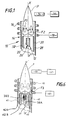
Sur la figure 1, on a représenté une torche à plasma destinée à dissocier les espèces chimiques d'un gaz comprenant des impuretés, pour générer des atomes libres et exciter les atomes ainsi obtenus en vue de la détermination de la concentration en impuretés.In Figure 1, a plasma torch is shown intended to dissociate the chemical species from a gas including impurities, to generate free atoms and excite the atoms thus obtained for the purpose of determining of the impurity concentration.
Par exemple, le gaz à analyser est constitué par un gaz utilisé dans le domaine de la fabrication des semiconducteurs, tel qu'un halogène ou un gaz fluoré , et les impuretés sont constituées par des éléments métalliques tels que le nickel, le fer, le manganèse...For example, the gas to be analyzed consists of a gas used in the field of semiconductor manufacturing, such as halogen or fluorinated gas, and the impurities are formed by metallic elements such than nickel, iron, manganese ...
On voit sur la figure 1 que la torche à plasma, désignée
par la référence générale numérique 10, comprend : un
injecteur central 12 configuré sous la forme d'un tube, un
manchon cylindrique externe 14 à double paroi (28/30) et un
bobinage 16 raccordé à une source de courant à haute
fréquence 18.We see in Figure 1 that the plasma torch, designated
by the general
La paroi 20 de l'injecteur délimite intérieurement un
canal 26 destiné à être raccordé à une source d'alimentation
de la torche 10 en un gaz à analyser (non représentée sur
cette figure).The
On voit donc sur la figure 1 que le manchon 14 comporte
une paroi interne 28 et une paroi externe 30 qui se prolonge
au-delà de l'extrémité libre de la paroi interne 28. Ces
parois sont réalisées en un matériau approprié pour
l'utilisation envisagée, c'est à dire capable de résister à
des hautes températures, par exemple en verre de silice. We therefore see in Figure 1 that the
Les parois interne et externe du manchon 14 délimitent
entre elles un canal annulaire cylindrique 32 raccordé, en
fonctionnement, à une source d'alimentation en un gaz
plasmagène, par exemple de l'Argon, en vue de la production
d'un plasma en sortie du manchon.The internal and external walls of the
La paroi externe 30 consécutive du manchon forme la
paroi externe de la torche 10 et est équipée, au voisinage
de sa tranche d'extrémité, du bobinage 16. Comme mentionné
précédemment, ce dernier est raccordé à la source de courant
à haute fréquence, de type classique, capable de délivrer au
bobinage un courant à une fréquence comprise entre 5 MHz et
100 MHz.The consecutive
Sous l'action de la source de courant 18, le bobinage
génère, comme cela est classique, un champ électromagnétique
radialement décroissant en direction de l'axe X-X' de la
torche 10.Under the action of the
Le gaz plasmagène, alimenté par l'intermédiaire du canal annulaire 32, selon un débit par exemple de 20 litres/minute, est délivré dans une zone dans laquelle la valeur du champ électromagnétique est sensiblement maximale. Ce dernier crée un plasma dans le gaz plasmagène par accélération de ses particules chargées.Plasma gas, supplied through the channel annular 32, at a flow rate for example of 20 liters / minute, is delivered in an area where the value of the electromagnetic field is substantially maximum. The latter creates a plasma in the plasma gas by acceleration of its charged particles.
Comme mentionné précédemment, et comme représenté sur la flèche F1 de la figure 1, la plasma présente des mouvements de recirculation sous l'effet des forces de Lorentz s'appliquant aux particules chargées. Sous l'effet de ces forces, la vitesse du gaz est négative dans la zone axiale, c'est à dire que les particules sont animées d'un mouvement dirigé vers l'amont de la torche, en considérant le sens d'écoulement des gaz, qui s'oppose à l'introduction du gaz à analyser.As previously mentioned, and as shown in the arrow F1 in figure 1, the plasma shows movements of recirculation under the effect of Lorentz forces applying to charged particles. Under the effect of these forces, the gas velocity is negative in the axial zone, that is to say that the particles are animated by a movement directed upstream of the torch, considering the direction gas flow, which opposes the introduction of gas to analyze.
Par ailleurs, dans une zone radialement décalée par rapport à l'axe X-X', ces forces tendent à diriger le gaz à analyser vers la zone périphérique.Furthermore, in an area radially offset by relative to the axis XX ', these forces tend to direct the gas to analyze towards the peripheral zone.
Comme on le voit sur la figure 1, le gaz à analyser est
introduit dans le canal interne d'alimentation 26 selon la
direction représentée par la flèche F2 dans la zone axiale,
à un débit couramment de l'ordre de quelques ml/minute à
quelques centaines de ml/minute. As seen in Figure 1, the gas to be analyzed is
introduced into the
On voit enfin sur la figure 1 qu'un détecteur
photoélectrique 34 est relié à une unité de traitement 36
effectuant le calcul de la concentration en impuretés dans
le gaz à partir de la valeur de la longueur d'onde du
rayonnement émis par les particules d'impuretés excitées,
comme cela sera décrit en détail par la suite.We finally see in Figure 1 that a detector
photoelectric 34 is connected to a
On a représenté sur la figure 2 un mode de réalisation de l'injecteur à diamètre variable selon l'invention.FIG. 2 shows an embodiment of the variable diameter injector according to the invention.
L'injecteur 12 est ici formé de deux tubes coaxiaux
externe (20) et interne (90), le tube interne 90 étant apte
à coulisser verticalement à l'intérieur du tube externe.The
Cet effet coulissant est, pour le mode de réalisation
représenté ici, obtenu à l'aide d'une commande pneumatique
91, agissant sur un micro-vérin 92.This sliding effect is, for the embodiment
shown here, obtained by
On note aussi sur cette figure la présence d'une pièce
de fixation 93, solidaire de la tige du micro-vérin et du
tube interne 90.We also note on this figure the presence of a room
fixing 93, integral with the rod of the micro-jack and the
Ce tube interne, mû par le micro-vérin selon le
mécanisme qui vient d'être décrit, peut donc coulisser
verticalement à l'intérieur du tube externe 20.This internal tube, driven by the micro-cylinder according to the
mechanism which has just been described, can therefore slide
vertically inside the
On conçoit alors que l'injecteur peut selon ce mode de réalisation adopter deux configurations :
- une position haute du
tube interne 90 dont l'extrémité supérieure est alors ramenée au niveau de l'extrémité supérieure du tube externe. Le gaz à analyser est injecté et pénètre alors dans le plasma par le « petit » diamètre du tube interne de l'injecteur ; - une position basse du tube interne 90 (un exemple de telle position basse est représentée figure 2) dont l'extrémité supérieure est alors positionnée au dessous de l'extrémité supérieure du tube externe. Le gaz à analyser est injecté et pénètre alors dans le plasma par le « grand » diamètre du tube externe de l'injecteur.
- a high position of the
inner tube 90, the upper end of which is then brought back to the level of the upper end of the outer tube. The gas to be analyzed is injected and then enters the plasma through the "small" diameter of the internal tube of the injector; - a lower position of the inner tube 90 (an example of such a lower position is shown in Figure 2) whose upper end is then positioned below the upper end of the outer tube. The gas to be analyzed is injected and then enters the plasma through the "large" diameter of the injector's outer tube.
L'abaissement de l'extrémité supérieure du tube interne par rapport à l'extrémité supérieure du tube externe pourra typiquement être d'un ordre de grandeur de 1 à 2 cm.Lowering the upper end of the inner tube relative to the upper end of the outer tube may typically be of the order of 1 to 2 cm.
Comme il apparaítra clairement à l'homme du métier, on a
représenté ici un injecteur à deux tubes coaxiaux 20 et 90,
permettant de faire varier le diamètre de l'injection selon
deux valeurs, mais on conçoit que l'on peut adopter, sans
sortir à aucun moment du cadre de la présente invention, une
structure à plusieurs tubes coaxiaux (plus de 2), permettant
selon le jeu de coulissement des tubes à l'intérieur du tube
le plus externe, de faire varier le diamètre de l'injection
selon plusieurs valeurs possibles.As will be clear to those skilled in the art, we have
shown here an injector with two
On a représenté sur la figure 3 un autre mode de réalisation de la torche à plasma selon l'invention.Another mode of realization of the plasma torch according to the invention.
On note que pour le mode de réalisation représenté en
figure 3, la torche comporte ici un injecteur central 12 un
peu particulier qui comporte, conformément à un des modes
avantageux de mise en oeuvre de l'invention précédemment
évoqués, un tube additionnel extérieur 22, coaxial au tube
principal 20, et délimitant ainsi deux canaux coaxiaux
interne et externe destinés respectivement l'un à
l'alimentation de la torche en gaz à analyser et l'autre à
l'alimentation de la torche en un gaz de guidage dudit gaz à
analyser dans le plasma.Note that for the embodiment shown in
Figure 3, the torch here comprises a central injector 12 a
little particular which comprises, in accordance with one of the modes
advantageous implementation of the invention previously
mentioned, an additional
Les travaux menés à bien par la Demanderesse ont en
effet démontré qu'une telle configuration est avantageuse
afin de délivrer le gaz à analyser à l'intérieur du tube
interne à la paroi 20, tandis qu'un gaz de « guidage » est
délivré dans l'espace annulaire intermédiaire entre la paroi
additionnelle 22 et le tube principal 20 de l'injecteur.The work carried out by the Applicant has in
demonstrated effect that such a configuration is advantageous
in order to deliver the gas to be analyzed inside the tube
internal to the
Le gaz de guidage est délivré selon un débit par exemple de l'ordre de quelques centaines de ml/minute, et assure donc le guidage du gaz à analyser dans le plasma P. Ce guidage s'oppose ainsi à l'action des forces de Lorentz sur le gaz à analyser en contribuant à éviter que le gaz à analyser ne soit dévié (i.e faire en sorte que la totalité de l'échantillon atteigne le plasma).The guide gas is delivered at a flow rate for example of the order of a few hundred ml / minute, and ensures therefore guiding the gas to be analyzed in the plasma P. This guidance thus opposes the action of Lorentz forces on the gas to be analyzed by helping to prevent the gas from analyze is deflected (i.e. ensuring that the whole of the sample reaches the plasma).
En outre, et comme représenté par les flèches F3, le gaz de guidage, dont la composition est parfaitement maítrisée, étant entraíné vers la périphérie de la torche au lieu du gaz à analyser, on évite ainsi des dépôts, sur la paroi externe 30, des particules entrant dans la constitution du gaz à analyser, en choisissant le gaz de guidage de façon appropriée. Avantageusement, le gaz de guidage comporte de l'hélium ou de l'argon ou un mélange de tels gaz. In addition, and as shown by the arrows F3, the gas guide, whose composition is perfectly controlled, being driven towards the periphery of the torch instead of gas to be analyzed, deposits on the wall are thus avoided external 30, particles forming part of the gas to be analyzed, choosing the guide gas so appropriate. Advantageously, the guide gas comprises helium or argon or a mixture of such gases.
On conçoit que pour l'invention, l'injection d'un gaz de guidage à l'intérieur de l'injecteur est optionnelle.It is understood that for the invention, the injection of a gas of guidance inside the injector is optional.
Avantageusement, il est possible d'injecter dans
l'intervalle compris entre le manchon 28/30 et l'injecteur
de la torche, un flux d'argon afin de décaler l'extrémité
proximale du plasma P de la tranche d'extrémité du manchon.Advantageously, it is possible to inject into
the interval between the
Comme il apparaítra clairement à l'homme du métier, on a représenté sur cette figure un injecteur tubulaire à double paroi permettant l'injection du gaz à analyser et d'un gaz de guidage du gaz à analyser dans le plasma.As will be clear to those skilled in the art, we have shown in this figure a double tubular injector wall allowing the injection of the gas to be analyzed and a gas for guiding the gas to be analyzed in the plasma.
Mais pour des raison de lisibilité de la figure, qui on le voit est relativement chargée, on n'a pas représenté ici de moyens de faire varier le diamètre d'injection du gaz à analyser selon l'invention.But for the sake of readability of the figure, which see it is relatively busy, we have not shown here means of varying the gas injection diameter to analyze according to the invention.
On a ainsi représenté un tube 20 simple d'injection du
gaz à analyser, sans par exemple représenter la présence
d'un tube interne 90 coaxial au tube externe 20, et pouvant
coulisser à l'intérieur de ce tube externe 20 (mode de
réalisation de la figure 2). On conçoit en effet qu'une
telle représentation aurait alourdi à l'excès cette figure
3.A
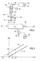
La description d'une installation d'analyse d'un gaz va maintenant être faite en référence à la figure 4.The description of a gas analysis installation will now be made with reference to figure 4.
On voit sur cette figure, que l'installation,
schématiquement représentée, comporte une torche à plasma 54
conforme à l'invention, par exemple similaire à la torche
décrite dans le cadre des figures 1 et 2, associée à un
générateur de courant à haute fréquence 56, et à un
photodétecteur 58 lui-même relié à une unité de traitement
60.We see in this figure, that the installation,
schematically shown, includes a plasma torch 54
according to the invention, for example similar to the torch
described in the context of FIGS. 1 and 2, associated with a
high frequency current generator 56, and at a
On voit sur cette figure que le manchon cylindrique externe de la torche 54 est alimenté en Argon (Ar) pour créer un plasma de préférence à pression atmosphérique ou en légère dépression.We see in this figure that the cylindrical sleeve torch 54 external is supplied with Argon (Ar) for create a plasma preferably at atmospheric pressure or slight depression.
Par ailleurs, l'injecteur 62, devant permettre
l'introduction dans le plasma du gaz à analyser, est
raccordé à un premier mélangeur 64 comprenant une première
entrée 66 alimentée en un gaz inerte, tel que de l'Argon,
permettant d'augmenter la vitesse d'entraínement du gaz à
analyser, et une deuxième entrée 68 raccordée à la sortie
d'un deuxième mélangeur 70.Furthermore, the
Ce dernier comporte une première entrée 72 alimentée en gaz G à analyser et une deuxième entrée 74 raccordée à la sortie d'une unité 75 d'élaboration d'échantillons étalons, unité qui comporte :
une source 80 de solutions de sels dissous de un ou plusieurs éléments ;- une unité 78 de nébulisation ;
- une unité 76 de désolvatation ;
- a
source 80 of solutions of dissolved salts of one or more elements; - a
nebulization unit 78; - a
desolvation unit 76;
L'unité 76 comporte une entrée permettant l'admission
d'aérosols en provenance de l'unité 78.
L'unité 78 comporte par ailleurs une entrée 86 de gaz
permettant l'admission d'un gaz inerte tel que de l'argon.
Pour étalonner l'installation, on introduit les éléments à doser, à une concentration connue et sous une forme donnée (liquide, solide ou gazeuse) la plus proche de celle des éléments à déterminer dans les échantillons de gaz G. Ainsi, dans un gaz, les éléments polluants peuvent être sous forme solide ou gazeuse, et plus rarement liquide. On sait par contre que les particules solides, souvent présentes dans les gaz chimiques ont une dimension inférieure à un micron. Pour une telle dimension, ces petites particules sont rapidement volatilisées et engendrent dans un plasma d'Argon une intensité lumineuse identique à celle engendrée par des composés gazeux.To calibrate the installation, we introduce the elements to be dosed, at a known concentration and in a given form (liquid, solid or gaseous) closest to that of elements to be determined in the gas samples G. Thus, in a gas, the polluting elements can be in the form solid or gaseous, and more rarely liquid. We know by against that solid particles, often present in chemical gases are less than one micron in size. For such a dimension, these small particles are rapidly volatilized and generate in an Argon plasma a light intensity identical to that generated by gaseous compounds.
Ainsi à titre illustratif, pour effectuer l'étalonnage
de l'installation en un élément métallique donné, on génère,
à l'aide de l'unité de nébulisation 78, à partir d'une
solution 80 d'un sel de l'impureté métallique considérée, un
aérosol comportant typiquement de la vapeur d'eau, des
solvants, ainsi que les particules en question.So by way of illustration, to perform the calibration
of the installation in a given metallic element, we generate,
using the
L'arrivée de gaz 86 (par exemple d'argon) transporte cet aérosol vers l'unité de désolvatation.The arrival of gas 86 (for example argon) transports this aerosol to the desolvation unit.
Suit alors une opération de désolvatation dans l'unité
76, consistant à chauffer le gaz aérosol pour permettre la
l'évaporation et la condensation de l'eau et du ou des
solvants éventuels (éliminés par une sortie 82 de l'unité
76), permettant ainsi de récupérer un gaz transportant les
particules initialement introduites, maintenant sèches ou
substantiellement sèches, à une teneur maítrisée, fonction
notamment de la concentration des particules dans
l'échantillon 80.Then follows a desolvation operation in the
On se reportera, pour plus de détails concernant l'élaboration d'étalons de particules métalliques par nébulisation/désolvatation aux documents suivants : C. Hélou, « Analyse de traces d'éléments dans les gaz par spectroscopie d'émission utilisant un plasma HF », Thèse de troisième cycle, Université Claude Bernard, Lyon/France, 1981, ou encore à la publication aux noms de C. Trassy et al faite dans la revue High Temperature Chemical Processes, 1993, vol. 2, 439-447.We will refer, for more details concerning the development of metal particle standards by nebulization / desolvation to the following documents: C. Hélou, "Analysis of traces of elements in gases by emission spectroscopy using HF plasma ”, Thesis of postgraduate, Claude Bernard University, Lyon / France, 1981, or to the publication in the names of C. Trassy et al made in the journal High Temperature Chemical Processes, 1993, vol. 2, 439-447.
Les échantillons étalons ainsi créés sont entraínés dans le plasma P par un gaz similaire au gaz G, mais dépourvu d'impureté, ou encore par de l'Argon.The standard samples thus created are trained in plasma P by a gas similar to gas G, but lacking impurity, or by Argon.
L'intensité lumineuse émise par les impuretés est
détectée par le photodétecteur 58 (monochromateur et/ou
polychromateur) puis stockée dans une mémoire 84 de l'unité
d'analyse 60.The light intensity emitted by the impurities is
detected by photodetector 58 (monochromator and / or
polychromator) then stored in a
Après avoir étalonné l'installation, le gaz G est
présenté en entrée du mélangeur 70 et est injecté dans le
plasma P.After calibrating the installation, the gas G is
presented at the input of
L'intensité lumineuse émise par les impuretés du gaz G
est ensuite présentée en entrée de l'unité d'analyse 60.The light intensity emitted by the impurities of gas G
is then presented at the input of the
Cette dernière comporte des moyens de calcul de type
classique, assurant la comparaison entre l'intensité
lumineuse détectée des impuretés à doser et les valeurs de
référence préalablement obtenues et stockées dans la mémoire
84.The latter includes means of calculation of the type
classic, ensuring the comparison between the intensity
light detected impurities to be measured and the values of
reference previously obtained and stored in the
La concentration exacte en particules contenues dans le gaz G est ainsi par exemple obtenue par identification de l'échantillon dont le signal correspondant présente une longueur d'onde et une intensité identiques aux valeurs mesurées à partir du gaz G.The exact concentration of particles in the gas G is thus for example obtained by identification of the sample whose corresponding signal has a wavelength and intensity identical to the values measured from gas G.
Comme bien connu de l'homme du métier (méthode dite « des ajouts dosés ») il est également possible, en variante, de déterminer la concentration C des particules dans le gaz G à partir du calcul de la fonction liant l'intensité lumineuse I des particules dans le plasma et la concentration en particules C dans celui-ci (figure 5).As well known to those skilled in the art (so-called method "Metered additions") it is also possible, by variant, to determine the concentration C of the particles in gas G from the calculation of the binding function the light intensity I of the particles in the plasma and the concentration of particles C therein (FIG. 5).
On sait en effet que pour un gaz dépourvu d'un type donné de particules, c'est à dire dont la concentration est nulle, l'intensité lumineuse à la longueur d'onde correspondante est nulle. Il est ainsi possible de déterminer la pente de la courbe A liant l'intensité I et la concentration C à partir d'une seule mesure de l'intensité lumineuse I1 émise par un gaz pur mélangé à un échantillon de concentration C1.We know indeed that for a gas devoid of a type given of particles, i.e. whose concentration is zero, the light intensity at wavelength corresponding is null. It is thus possible to determine the slope of curve A linking intensity I and the concentration C from a single intensity measurement light I1 emitted by a pure gas mixed with a sample of concentration C1.
On sait par ailleurs que pour des conditions de plasma identiques, en particulier pour une température de plasma identique, la pente de la courbe B, obtenue à partir d'un gaz, liant l'intensité I et la concentration C en impuretés est identique à celle de la courbe A obtenue à partir du même gaz à l'état pur.We also know that for plasma conditions identical, in particular for a plasma temperature identical, the slope of curve B, obtained from a gas, linking intensity I and concentration C of impurities is identical to that of curve A obtained from same pure gas.
Ainsi, pour effectuer le dosage du gaz G à analyser,
ayant une concentration inconnue Cp en particules, il suffit
d'ajouter à ce gaz des particules à une concentration C2
connue, prélevées à partir d'un échantillon 80 et de mesurer
l'intensité I2 correspondante. On obtient ainsi la valeur de
la concentration Cp par extrapolation de la courbe B à
l'aide des moyens de calcul de l'unité d'analyse 60.Thus, to carry out the dosage of the gas G to be analyzed, having an unknown concentration C p in particles, it suffices to add to this gas particles at a known concentration C2, taken from a
Les travaux menés à bien par la Demanderesse à l'aide d'une installation d'analyse telle que celle décrite dans le cadre de la figure 4, tant dans des cas d'analyse d'impuretés métalliques dans des gaz à analyser qui étaient des gaz neutres tels l'argon, ou encore l'hélium ou l'azote, que dans des cas d'analyse d'impuretés métalliques dans des gaz triatomiques et plus, on permis de démontrer qu'il est avantageux d'utiliser, pour des gaz à analyser mono ou diatomiques, un diamètre de tube d'injection situé dans une gamme allant de 0,8 à 2 mm, et préférentiellement de 1,3 à 1,7 mm, tandis que pour des gaz à analyser triatomiques et plus (tels le silane ou encore l'ammoniac), un diamètre de tube d'injection situé dans une gamme allant de 1 à 3 mm, mais préférentiellement de 1,8 à 2,3 mm . The work carried out by the Applicant using an analysis installation such as that described in the frame of figure 4, both in case of analysis metallic impurities in gases to be analyzed which were neutral gases such as argon, or helium or nitrogen, only in cases of analysis of metallic impurities in triatomic gases and more, we allowed to demonstrate that it is advantageous to use, for gases to be analyzed mono or diatom, an injection tube diameter located in a range from 0.8 to 2 mm, and preferably from 1.3 to 1.7 mm, while for gases to be analyzed triatomic and more (such as silane or ammonia), an injection tube diameter in a range from from 1 to 3 mm, but preferably from 1.8 to 2.3 mm.
On conçoit que ces gammes de diamètre sont données à titre indicatif, comme tenant compte de la géométrie globale du système et des fréquences de fonctionnement utilisées pour les expérimentations, elles devraient être adaptées si ces paramètres venaient à être modifiés.We can see that these diameter ranges are given to indicative, as taking into account the overall geometry of the system and the operating frequencies used for experiments, they should be adapted if these parameters were to be modified.
Enfin, et de façon moins détaillée, la figure 6 représente une vue schématique en coupe axiale d'une torche à plasma conforme à l'invention, incorporant au niveau du manchon un tube intermédiaire.Finally, and in less detail, Figure 6 represents a schematic view in axial section of a torch plasma according to the invention, incorporating at the level of sleeve an intermediate tube.
La torche représentée figure 6 comporte en effet un tube
intermédiaire 40, coaxial au manchon 42, situé entre les
parois externe et interne du manchon (42A et 42B), le tube
intermédiaire 40 et la paroi externe 42A du manchon
délimitant un canal 45 d'alimentation en un gaz de
protection de la paroi externe (42A) de la torche contre des
dépôts solides.The torch shown in Figure 6 indeed has a tube
intermediate 40, coaxial with the
En outre, la torche représentée sur la figure 6 est
munie d'un bobinage 46 alimenté par une source de courant à
haute fréquence 48 et disposé au voisinage de la tranche
d'extrémité de la torche, et d'un photodétecteur 50 relié à
une unité de traitement 52.In addition, the torch shown in Figure 6 is
provided with a winding 46 supplied by a current source at
Pour des raisons de lisibilité, on a volontairement
grossi les espacements successifs 42A/40/42B, le tube 40
étant en pratique très proche de la paroi externe 42A de la
torche (ordre de grandeur du mm voire du 1/10e de mm).For reasons of legibility, was deliberately enlarged successive spacings 42A / 40 / 42B, the
Le canal d'alimentation 45 est donc raccordé à une
source d'alimentation en gaz de protection (non représentée)
capable de réagir avec les espèces susceptibles de se
déposer sur la surface interne de la paroi externe 42A de la
torche pour former un composé volatile.The
Ainsi à titre d'exemple, si le gaz à analyser comporte du silane (SiH4), gaz utilisé dans le domaine de la fabrication des semi-conducteurs, le gaz de protection comporte du chlore, éventuellement mélangé à de l'argon, réagissant avec le silicium pour former du SiCL4. Ce dernier composé étant une espèce volatile, on évite ainsi tout dépôt à base de silicium.Thus by way of example, if the gas to be analyzed comprises silane (SiH 4 ), a gas used in the field of semiconductor manufacturing, the shielding gas comprises chlorine, possibly mixed with argon, reacting with silicon to form SiCL 4 . As the latter compound is a volatile species, any deposit based on silicon is thus avoided.
On note que pour le mode de réalisation représenté en figure 6, la torche comporte ici un injecteur central 38 un à double paroi (38A, 38B) pour l'injection d'une part du gaz à analyser et d'autre part d'un gaz de « guidage ».Note that for the embodiment shown in Figure 6, the torch here comprises a central injector 38 a double-walled (38A, 38B) for injecting part of the gas to analyze and on the other hand a "guide" gas.
On ne commentera pas à nouveau ici la structure permettant l'injection d'un gaz de guidage au niveau de l'injecteur.We will not comment again here on the structure allowing the injection of a guide gas at the injector.
Ici encore, avantageusement, il est possible d'injecter dans l'intervalle compris entre le manchon et l'injecteur de la torche représentée sur la figure 6, un flux d'argon afin de décaler l'extrémité proximale du plasma P de la tranche d'extrémité du manchon.Here again, advantageously, it is possible to inject in the interval between the sleeve and the injector the torch shown in Figure 6, a flow of argon so offset the proximal end of plasma P from the wafer end of the sleeve.
Claims (12)
Applications Claiming Priority (4)
| Application Number | Priority Date | Filing Date | Title |
|---|---|---|---|
| FR9716620A FR2773300B1 (en) | 1997-12-29 | 1997-12-29 | PLASMA TORCH AND GAS ANALYSIS INSTALLATION USING SUCH A TORCH |
| FR9716619A FR2773299B1 (en) | 1997-12-29 | 1997-12-29 | PLASMA TORCH WITH ADJUSTABLE INJECTOR AND GAS ANALYSIS INSTALLATION USING SUCH A TORCH |
| FR9716619 | 1997-12-29 | ||
| FR9716620 | 1997-12-29 |
Publications (1)
| Publication Number | Publication Date |
|---|---|
| EP0930810A1 true EP0930810A1 (en) | 1999-07-21 |
Family
ID=26234031
Family Applications (1)
| Application Number | Title | Priority Date | Filing Date |
|---|---|---|---|
| EP98402992A Withdrawn EP0930810A1 (en) | 1997-12-29 | 1998-11-30 | Plasma torch with adjustable distributor and gas analysis system using such a torch |
Country Status (7)
| Country | Link |
|---|---|
| US (1) | US6236012B1 (en) |
| EP (1) | EP0930810A1 (en) |
| JP (1) | JPH11248632A (en) |
| KR (1) | KR19990063580A (en) |
| CN (1) | CN1235274A (en) |
| SG (1) | SG71892A1 (en) |
| TW (1) | TW412636B (en) |
Families Citing this family (11)
| Publication number | Priority date | Publication date | Assignee | Title |
|---|---|---|---|---|
| US7511246B2 (en) | 2002-12-12 | 2009-03-31 | Perkinelmer Las Inc. | Induction device for generating a plasma |
| US8633416B2 (en) * | 2005-03-11 | 2014-01-21 | Perkinelmer Health Sciences, Inc. | Plasmas and methods of using them |
| US8622735B2 (en) * | 2005-06-17 | 2014-01-07 | Perkinelmer Health Sciences, Inc. | Boost devices and methods of using them |
| US7742167B2 (en) | 2005-06-17 | 2010-06-22 | Perkinelmer Health Sciences, Inc. | Optical emission device with boost device |
| JP4489680B2 (en) * | 2005-10-03 | 2010-06-23 | 株式会社アドテック プラズマ テクノロジー | Microwave plasma generation method and apparatus |
| DE102006037995B4 (en) * | 2006-08-14 | 2009-11-12 | Bundesanstalt für Materialforschung und -Prüfung (BAM) | Solid state sample analysis method and apparatus for carrying out the same |
| FR2928641B1 (en) * | 2008-03-14 | 2010-03-26 | Centre Nat Rech Scient | SILICON PURIFICATION PROCESS FOR PHOTOVOLTAIC APPLICATIONS |
| JP5965743B2 (en) * | 2012-06-27 | 2016-08-10 | 株式会社日立ハイテクサイエンス | ICP device, spectroscopic analyzer, and mass spectrometer |
| AU2013290093B2 (en) | 2012-07-13 | 2017-09-21 | Peter Morrisroe | Torches and methods of using them |
| CN104363689B (en) * | 2014-11-18 | 2017-02-08 | 聚光科技(杭州)股份有限公司 | Analysis power source and mineral powder analysis device and method |
| US10139332B2 (en) * | 2014-12-29 | 2018-11-27 | Fluidigm Canada Inc. | Mass cytometry apparatus and methods |
Citations (8)
| Publication number | Priority date | Publication date | Assignee | Title |
|---|---|---|---|---|
| JPS60201239A (en) * | 1984-03-26 | 1985-10-11 | Shimadzu Corp | Plasma torch for icp emission spectrochemical analysis |
| EP0263031A2 (en) * | 1986-10-03 | 1988-04-06 | Commissariat A L'energie Atomique | Inductively coupled air-plasma apparatus for the spectrometric analysis of elements |
| US4766287A (en) * | 1987-03-06 | 1988-08-23 | The Perkin-Elmer Corporation | Inductively coupled plasma torch with adjustable sample injector |
| JPS63210754A (en) * | 1987-02-27 | 1988-09-01 | Shimadzu Corp | Sample introducing device for icp emission analysis |
| EP0296921A1 (en) * | 1987-06-10 | 1988-12-28 | L'air Liquide, Societe Anonyme Pour L'etude Et L'exploitation Des Procedes Georges Claude | Microwave plasma torch, device comprising such a torch and production procedure for powder operating them |
| EP0358212A2 (en) * | 1988-09-09 | 1990-03-14 | Matheson Gas Products, Inc. | Reactive gas sample introduction system for an inductively coupled plasma torch |
| EP0397468A2 (en) * | 1989-05-09 | 1990-11-14 | Varian Associates, Inc. | Spectroscopic plasma torch for microwave induced plasmas |
| JPH05180772A (en) * | 1991-12-27 | 1993-07-23 | Nkk Corp | Laser gasifying/inductively coupled plasma analysis and plasma torch |
Family Cites Families (6)
| Publication number | Priority date | Publication date | Assignee | Title |
|---|---|---|---|---|
| US4482246A (en) * | 1982-09-20 | 1984-11-13 | Meyer Gerhard A | Inductively coupled plasma discharge in flowing non-argon gas at atmospheric pressure for spectrochemical analysis |
| JPS59182345A (en) | 1983-03-31 | 1984-10-17 | Shimadzu Corp | Device for liquid chromatograph emission analysis |
| US5051557A (en) * | 1989-06-07 | 1991-09-24 | The United States Of America As Represented By The Secretary Of The Department Of Health And Human Services | Microwave induced plasma torch with tantalum injector probe |
| GB8917570D0 (en) * | 1989-08-01 | 1989-09-13 | Vg Instr Group | Plasma source mass spectrometry |
| US5233156A (en) * | 1991-08-28 | 1993-08-03 | Cetac Technologies Inc. | High solids content sample torches and method of use |
| US5908566A (en) * | 1997-09-17 | 1999-06-01 | The United States Of America As Represented By The Secretary Of The Navy | Modified plasma torch design for introducing sample air into inductively coupled plasma |
-
1998
- 1998-11-30 EP EP98402992A patent/EP0930810A1/en not_active Withdrawn
- 1998-12-11 TW TW087120614A patent/TW412636B/en not_active IP Right Cessation
- 1998-12-22 SG SG1998005896A patent/SG71892A1/en unknown
- 1998-12-25 JP JP10370101A patent/JPH11248632A/en active Pending
- 1998-12-28 KR KR1019980063916A patent/KR19990063580A/en not_active Application Discontinuation
- 1998-12-28 US US09/221,163 patent/US6236012B1/en not_active Expired - Fee Related
- 1998-12-29 CN CN98126221.XA patent/CN1235274A/en active Pending
Patent Citations (8)
| Publication number | Priority date | Publication date | Assignee | Title |
|---|---|---|---|---|
| JPS60201239A (en) * | 1984-03-26 | 1985-10-11 | Shimadzu Corp | Plasma torch for icp emission spectrochemical analysis |
| EP0263031A2 (en) * | 1986-10-03 | 1988-04-06 | Commissariat A L'energie Atomique | Inductively coupled air-plasma apparatus for the spectrometric analysis of elements |
| JPS63210754A (en) * | 1987-02-27 | 1988-09-01 | Shimadzu Corp | Sample introducing device for icp emission analysis |
| US4766287A (en) * | 1987-03-06 | 1988-08-23 | The Perkin-Elmer Corporation | Inductively coupled plasma torch with adjustable sample injector |
| EP0296921A1 (en) * | 1987-06-10 | 1988-12-28 | L'air Liquide, Societe Anonyme Pour L'etude Et L'exploitation Des Procedes Georges Claude | Microwave plasma torch, device comprising such a torch and production procedure for powder operating them |
| EP0358212A2 (en) * | 1988-09-09 | 1990-03-14 | Matheson Gas Products, Inc. | Reactive gas sample introduction system for an inductively coupled plasma torch |
| EP0397468A2 (en) * | 1989-05-09 | 1990-11-14 | Varian Associates, Inc. | Spectroscopic plasma torch for microwave induced plasmas |
| JPH05180772A (en) * | 1991-12-27 | 1993-07-23 | Nkk Corp | Laser gasifying/inductively coupled plasma analysis and plasma torch |
Non-Patent Citations (2)
| Title |
|---|
| PATENT ABSTRACTS OF JAPAN vol. 013, no. 001 (P - 808) 6 January 1989 (1989-01-06) * |
| TRASSY ET AL.: "Dosage d'éléments métalliques dans le gaz. Etude d'une méthode directe.", JOURNAL OF HIGH TEMPERATURE CHEMICAL PROCESSES., no. 2, December 1993 (1993-12-01), pages 439 - 447, XP002076765 * |
Also Published As
| Publication number | Publication date |
|---|---|
| JPH11248632A (en) | 1999-09-17 |
| CN1235274A (en) | 1999-11-17 |
| SG71892A1 (en) | 2000-04-18 |
| TW412636B (en) | 2000-11-21 |
| KR19990063580A (en) | 1999-07-26 |
| US6236012B1 (en) | 2001-05-22 |
Similar Documents
| Publication | Publication Date | Title |
|---|---|---|
| EP0930810A1 (en) | Plasma torch with adjustable distributor and gas analysis system using such a torch | |
| CA1194385A (en) | Device fabrication using gas-solid processes | |
| AU753047B2 (en) | Method for measuring the concentration of hydrogen peroxide vapor | |
| Wiltsche et al. | Matrix effects of carbon and bromine in inductively coupled plasma optical emission spectrometry | |
| Brockhinke et al. | Quantitative one-dimensional single-pulse multi-species concentration and temperature measurement in the lift-off region of a turbulent H 2/air diffusion flame | |
| EP2195643B1 (en) | System for analysing a low pressure gas by optical emission spectroscopy | |
| US20090301655A1 (en) | Plasma Processing Apparatus | |
| JPH10503289A (en) | Highly sensitive detection method for gaseous pollutants by internal cavity laser spectroscopy (ILS) | |
| EP3146314B1 (en) | Device for analysing an oxidisable molten metal using a libs technique | |
| EP2901139A1 (en) | Method and system for analysing particles in cold plasma | |
| FR2773299A1 (en) | Plasma torch with adjustable injector for gas analysis | |
| FR2773300A1 (en) | Plasma torch with adjustable injector for gas analysis | |
| EP1549933B1 (en) | Method and device for spectroscopy of the optical emission of a liquid excited by a laser | |
| EP0142414A2 (en) | Ion source, in particular for highly charged metallic ions, whose ion current is controlled | |
| EP1914535B1 (en) | Characterisation of gas by optical emission spectrometry | |
| CN1155655A (en) | Chamber effluent monitoring system and semiconductor processing system comprising absorption spectroscopy measurement system, and method of use | |
| EP3861328A1 (en) | Method for analyzing evaporation fumes, computer program product, analysis system and additive manufacturing facility associated therewith | |
| EP0305241A1 (en) | Process and apparatus for the treatment of surfaces using an electric after-glow in a flowing gas | |
| EP0051152B1 (en) | Optical coupling device | |
| EP0446080B1 (en) | Method and device for elemental analysis of a sample by mass spectrometry coupled to a high frequency induced plasma | |
| Timmins | Excitation of gallium, indium, selenium, tellurium, arsenic and antimony in a helium microwave-induced plasma | |
| WO2010046595A1 (en) | Method and system for analysing the stoichiometry of particles and process for manufacturing particles with stoichiometry control | |
| Lim et al. | Development and characterization of directly connected laser ablation/low-pressure inductively coupled plasma atomic emission spectrometry for solid sample analysis | |
| JP2004325380A (en) | Quantitative determination method for micro amount of boron | |
| JP2003075408A (en) | Method and apparatus for analysis of metal element in solid sample |
Legal Events
| Date | Code | Title | Description |
|---|---|---|---|
| PUAI | Public reference made under article 153(3) epc to a published international application that has entered the european phase |
Free format text: ORIGINAL CODE: 0009012 |
|
| AK | Designated contracting states |
Kind code of ref document: A1 Designated state(s): BE DE FR GB IE IT NL SE |
|
| AX | Request for extension of the european patent |
Free format text: AL;LT;LV;MK;RO;SI |
|
| 17P | Request for examination filed |
Effective date: 20000121 |
|
| AKX | Designation fees paid |
Free format text: BE DE FR GB IE IT NL SE |
|
| RAP1 | Party data changed (applicant data changed or rights of an application transferred) |
Owner name: L'AIR LIQUIDE, S.A. A DIRECTOIRE ET CONSEIL DE SUR |
|
| GRAH | Despatch of communication of intention to grant a patent |
Free format text: ORIGINAL CODE: EPIDOS IGRA |
|
| STAA | Information on the status of an ep patent application or granted ep patent |
Free format text: STATUS: THE APPLICATION HAS BEEN WITHDRAWN |
|
| 18W | Application withdrawn |
Effective date: 20030203 |