EP0932228B2 - Split-pumped dual stage optical fiber amplifier - Google Patents
Split-pumped dual stage optical fiber amplifier Download PDFInfo
- Publication number
- EP0932228B2 EP0932228B2 EP99101143A EP99101143A EP0932228B2 EP 0932228 B2 EP0932228 B2 EP 0932228B2 EP 99101143 A EP99101143 A EP 99101143A EP 99101143 A EP99101143 A EP 99101143A EP 0932228 B2 EP0932228 B2 EP 0932228B2
- Authority
- EP
- European Patent Office
- Prior art keywords
- power
- amplifier
- stage
- power level
- pump source
- Prior art date
- Legal status (The legal status is an assumption and is not a legal conclusion. Google has not performed a legal analysis and makes no representation as to the accuracy of the status listed.)
- Expired - Lifetime
Links
Images

Classifications
-
- H—ELECTRICITY
- H01—ELECTRIC ELEMENTS
- H01S—DEVICES USING THE PROCESS OF LIGHT AMPLIFICATION BY STIMULATED EMISSION OF RADIATION [LASER] TO AMPLIFY OR GENERATE LIGHT; DEVICES USING STIMULATED EMISSION OF ELECTROMAGNETIC RADIATION IN WAVE RANGES OTHER THAN OPTICAL
- H01S3/00—Lasers, i.e. devices using stimulated emission of electromagnetic radiation in the infrared, visible or ultraviolet wave range
- H01S3/05—Construction or shape of optical resonators; Accommodation of active medium therein; Shape of active medium
- H01S3/06—Construction or shape of active medium
- H01S3/063—Waveguide lasers, i.e. whereby the dimensions of the waveguide are of the order of the light wavelength
- H01S3/067—Fibre lasers
- H01S3/06754—Fibre amplifiers
- H01S3/06758—Tandem amplifiers
-
- H—ELECTRICITY
- H01—ELECTRIC ELEMENTS
- H01S—DEVICES USING THE PROCESS OF LIGHT AMPLIFICATION BY STIMULATED EMISSION OF RADIATION [LASER] TO AMPLIFY OR GENERATE LIGHT; DEVICES USING STIMULATED EMISSION OF ELECTROMAGNETIC RADIATION IN WAVE RANGES OTHER THAN OPTICAL
- H01S2301/00—Functional characteristics
- H01S2301/02—ASE (amplified spontaneous emission), noise; Reduction thereof
-
- H—ELECTRICITY
- H01—ELECTRIC ELEMENTS
- H01S—DEVICES USING THE PROCESS OF LIGHT AMPLIFICATION BY STIMULATED EMISSION OF RADIATION [LASER] TO AMPLIFY OR GENERATE LIGHT; DEVICES USING STIMULATED EMISSION OF ELECTROMAGNETIC RADIATION IN WAVE RANGES OTHER THAN OPTICAL
- H01S3/00—Lasers, i.e. devices using stimulated emission of electromagnetic radiation in the infrared, visible or ultraviolet wave range
- H01S3/09—Processes or apparatus for excitation, e.g. pumping
- H01S3/091—Processes or apparatus for excitation, e.g. pumping using optical pumping
- H01S3/094—Processes or apparatus for excitation, e.g. pumping using optical pumping by coherent light
- H01S3/094003—Processes or apparatus for excitation, e.g. pumping using optical pumping by coherent light the pumped medium being a fibre
-
- H—ELECTRICITY
- H01—ELECTRIC ELEMENTS
- H01S—DEVICES USING THE PROCESS OF LIGHT AMPLIFICATION BY STIMULATED EMISSION OF RADIATION [LASER] TO AMPLIFY OR GENERATE LIGHT; DEVICES USING STIMULATED EMISSION OF ELECTROMAGNETIC RADIATION IN WAVE RANGES OTHER THAN OPTICAL
- H01S3/00—Lasers, i.e. devices using stimulated emission of electromagnetic radiation in the infrared, visible or ultraviolet wave range
- H01S3/09—Processes or apparatus for excitation, e.g. pumping
- H01S3/091—Processes or apparatus for excitation, e.g. pumping using optical pumping
- H01S3/094—Processes or apparatus for excitation, e.g. pumping using optical pumping by coherent light
- H01S3/094061—Shared pump, i.e. pump light of a single pump source is used to pump plural gain media in parallel
Definitions
- the present invention relates to a doped fiber amplifier arrangement and, specifically, to a dual-stage amplifier with a passive pump splitting arrangement which allows low noise operation and variable signal gain with a single pump laser.
- Erbium doped fiber amplifiers have revolutionized lightwave systems. These amplifiers have replaced detection and regeneration systems in long transglobal systems where fiber attenuation and dispersion act to degrade the transmitted signal. Further, fiber amplifiers are utilized in wide area signal distribution systems where distribution losses become appreciable.
- the fiber amplifier is placed in-line with the signal carrying fiber to allow the optical signal to enter the Erbium fiber and directly experience gain.
- Connectors or fusion splices may be used to attach the amplifier to the signal fiber.
- Input and output isolators are typically utilized in unidirectional systems to control the direction of signals and amplified spontaneous emissions from the Erbium gain medium.
- fiber amplifiers take many forms. Multiple stages may be utilized to optimize performance. Additionally, either 980 nm or 1480 nm laser sources are typically utilized to co-, counter, or co- and counter-propagate pump power within each Erbium fiber amplifier stage. Wavelength multiplexers are utilized to couple the pump power to the Erbium fiber. Inter- and intra-stage isolators and filters maybe utilized to effect the noise and gain performance. In today's applications, a specific design consideration is flattening gain over the wavelength range of interest by selecting appropriate lengths of Erbium fiber or by utilizing an appropriate gain shaping filter.
- post (or booster) amplifier (2) in-line amplifier, or, (3) pre-amplifier.
- the post and pre-amplifier are often called terminal amplifiers. They are typically found at the ends (terminals) of a lightwave system, while the in-line amplifier is found mid-span in the system. Functionally, amplifier types differ in their input and output specifications.
- the post amplifier operates in saturation to produce high optical output power (+17 to +24 dBm).
- the pre-amplifier is designed to deliver large small signal gain with minimal noise figure. Typically, a pre-amplifier will deliver > 30 dB of small signal gain with output power > -10 dBm.
- the in-line amplifier delivers 10 to 20 dB of gain from input power levels between -20 and -10 dBm.
- Erbium doped fiber amplifiers are commercially available from many suppliers. One or two stage amplifiers with one or more pumps per stage, either at 1480 nm or 980 nm are common. The bulk of commercial amplifiers have a limit range of variable gain with which to either stabilize output power or accommodate a range of input conditions.
- An often used method of adjusting the gain state of a fiber amplifier is by dynamically adjusting the pump power in one or more stages.
- the most common way for controlling amplifier gain without sacrificing the total amplifier noise figure is by adjusting the pump power in the second stage of a dual-stage amplifier, i.e., leaving the first stage gain high enough to insure a reasonable total noise figure.
- This method usually allows approximately 22 dB of variable gain and requires a minimum of two pumps, one for each stage. Further, the second stage gain control is difficult due to the rapid nonlinear change of gain with decreasing pump power.
- a high output power, high gain, and low noise two-stage optical amplifier suitable for use as a repeater for a long haul lightwave communication system is disclosed, the optical amplifier having two stages comprising erbium-doped fibers.
- Pump light is generated by a laser diode, using a separate laser diode to generate pump light used in the second stage of the optical amplifier.
- a single laser diode may be coupled into a splitter to distribute pump light between a first stage and second stage, of the optical amplifier
- a split-pumped, dual-stage optical amplifier as defined in claim 1, is provided. More particularly, the invention relates to a dual-stage, doped fiber amplifier which utilizes a single pump laser and a passive splitter to simultaneously and unequally pump both stages.
- a dual-stage doped fiber amplifier which utilizes a single pump laser and a passive 90:10 power splitter.
- the passive splitter couples 90% of the power output from the single pump laser to the first stage of an amplifier and 10% of the pump power to the second stage.
- the present invention provides for the achievement of the performance characteristics of an isolated dual-stage amplifier with the cost effective use of a single pump laser.
- An extended range of variable gain is achievable when compared against the gain achievable with an individually pumped dual-stage amplifier. Additionally, gain variation with pump power is more gradual which allows for easier control of the amplifier gain state.
- a method for pumping a dual-stage fiber amplifier and a method for controlling the gain and noise characteristics of a duel-stage fiber amplifier are defined in Claims 10 and 16 respectively.
- Fig. 1 illustrates one embodiment for a split pumped, dual-stage optical fiber amplifier of the present invention. As shown, the disclosed embodiment includes a single pump source 100, a passive power splitter 110, a first in-line amplifier stage 120 and a second in-line amplifier stage 130.
- First in-line amplifier stage 120 and second in-line amplifier stage 130 are both erbium-doped fibers. Both amplifier stages are placed in-line with the signal carrying fiber 140 and may be attached to signal fiber 140 by utilizing either connectors or fusion splices.
- the length of the fiber utilized for each in-line fiber amplifier stage is dependent upon the specific characteristics of the system into which the amplifier is inserted and therefore, the two stages can either be of the same length or of different lengths.
- the signal carried on signal carrying fiber 140 enters the fiber amplifier from end 142 of the signal fiber and exits the fiber amplifier at end 146.
- the signal to be amplified travels from left to right along signal fiber 140.
- Input tap 143 is provided to tap a portion of the input signal travelling along signal fiber 140 and provide this signal to input signal level (ISL) detector 144.
- output tap 147 taps a portion of the output signal from the amplifier and provides this signal to output signal level (OSL) detector 148.
- optical isolators 145 and 149 are provided. Input and output isolators 145 and 149, respectively, are typically utilized in unidirectional systems to control the direction of signals and amplified spontaneous emissions from the Erbium gain medium.
- the tapped input and output signals from taps 143 and 147 can be utilized to measure the performance of the fiber amplifier.
- the optical taps, detectors and isolators are optional features and are not required when practicing the present invention.
- filter 150 and isolator 152 are also provided.
- Interand intra-stage isolators and filters maybe utilized to effect the noise and gain performance of the amplifier.
- Filter 150 can be, for example, a noise filter, a signal shaping filter or a bandpass filter, however, the decision of whether or not to include filter 150 and isolator 152 is dependent upon the requirements of the particular system into which the amplifier is inserted and thus are not required for the present invention.
- Single pump source 100 is a pump laser that provides power output at a wavelength, for example, of 980 nanometers (nm).
- the power from pump source 100 is coupled onto output fiber 102 and is then input to passive power splitter 110.
- Power splitter 110 splits the power from pump source 100 into a first power level 112 and a second power level 114.
- the power of first power level 112 is coupled onto an output fiber 112A from splitter 110 which is then coupled to first in-line amplifier stage 120 to provide pump power to the first stage.
- Second power level 114 is coupled onto an output fiber 114A from splitter 110 for utilization as the pump power for second in-line amplifier stage 130.
- Wavelength multiplexers are utilized to couple the pump power to the Erbium fiber.
- first in-line amplifier stage 120 is counter-pumped and second in-line amplifier stage 130 is co-pumped.
- the invention is not limited to this configuration.
- Each amplifier stage can be co-pumped or counter-pumped, depending upon the requirements of the system into which the amplifier is inserted.
- Splitter 110 splits the power output from pump source 100 into a first power level 112, which is 90% of the output from pump source 100, and a second power level 114, which is 10% of the output from the pump source.
- the ratio of the power split from single pump source 100 to first power level 112 and second power level 114 can be adjusted by selecting splitter 110 to provide the desired power ratios.
- a power ratio of 95% for first power level 112 and 5% for second power level 114 and a ratio of 85% and 15%, respectively, for example, are obtainable.
- Selection of the power ratio for the power supplied to the first stage in-line amplifier and the second stage in-line amplifier is dependent upon the design requirements for the particular system. Because one factor affecting the performance of the amplifier is the power supplied to both the first stage and the second stage of the amplifier, adjustment of the power supplied to each stage, as provided from a single pump source, can be utilized to control the performance of the amplifier.
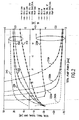
- Fig. 2 shows the performance characteristics of the single pump, dual-stage amplifier design of the present invention.
- the gain and performance characteristics for the amplifier can be controlled by adjusting the ratio of the power supplied to each amplifier stage. This control of the amplifier by providing unequal power levels to each amplifier stage is achieved by utilizing a single pump source to pump both stages.
- Fig. 2 provides graphs for the signal gain and the noise figure versus total pump power for the split pump power ratios of 90%/10%, 95%/5%, and 85%/15%, as supplied to the first in-line amplifier stage and the second in-line amplifier stage, respectively.
- the graphs clearly show that by controlling the power supplied to each stage of the amplifier, as supplied by a single pump source, the performance characteristics of the amplifier can be adjusted. In selecting the particular power levels that are to be supplied to each stage of the amplifier, the system designer will consider the particular requirements of the system into which the amplifier is to be installed.
- the power levels supplied to the first and second stages of the amplifier can be adjusted to result in a noise level for the amplifier that is below the threshold value.
- curves 200 and 200A show the performance characteristics for the embodiment where 90% of the pump output power from pump source 100 is provided to first in-line stage 120 and 10% of the pump power from the pump source is provided to second in-line stage 130.
- Curves 210 and 210A illustrate the performance characteristics of the amplifier where 95% of the pump power is provided to the first stage and 5% of the pump power is provided to the second stage.
- curve 230 shows the gain performance and curve 230A shows the noise performance.
- curve 240 shows the gain performance and curve 240A shows the noise performance for this amplifier.
- the dual-stage/single pump configuration provides for more linearized gain, particularly at lower total pump power levels, comparable total gain, and much improved noise performance.
- the dual-stage/single pump configuration When comparing the performance curves for the dual-stage/dual pump amplifier configuration to the performance curves for the dual-stage/single pump amplifier of the present invention, the dual-stage/single pump configuration also provides for more linearized gain at lower total pump power levels, an extended range of variable gain, and comparable performance in total gain and noise.
- the present invention achieves the desirable low noise performance characteristic of the dual-stage/dual pump amplifier while only requiring a single pump source, which results in cost efficiencies. Additionally, the performance of the amplifier can be controlled by adjusting the power supplied to each amplifier stage from the single pump source.
- Pump source 100 is disclosed as a laser operating at 980 nm, however, other pump source wavelengths, e.g., 1480 nm, can be utilized. Additionally, both in-line fiber amplifier stages are disclosed as being erbium-doped fibers, however, other fiber amplifier designs can be incorporated into the present invention.
Description
- The present invention relates to a doped fiber amplifier arrangement and, specifically, to a dual-stage amplifier with a passive pump splitting arrangement which allows low noise operation and variable signal gain with a single pump laser.
- Erbium doped fiber amplifiers have revolutionized lightwave systems. These amplifiers have replaced detection and regeneration systems in long transglobal systems where fiber attenuation and dispersion act to degrade the transmitted signal. Further, fiber amplifiers are utilized in wide area signal distribution systems where distribution losses become appreciable.
- In practice, the fiber amplifier is placed in-line with the signal carrying fiber to allow the optical signal to enter the Erbium fiber and directly experience gain. Connectors or fusion splices may be used to attach the amplifier to the signal fiber. Input and output isolators are typically utilized in unidirectional systems to control the direction of signals and amplified spontaneous emissions from the Erbium gain medium.
- Topologically, fiber amplifiers take many forms. Multiple stages may be utilized to optimize performance. Additionally, either 980 nm or 1480 nm laser sources are typically utilized to co-, counter, or co- and counter-propagate pump power within each Erbium fiber amplifier stage. Wavelength multiplexers are utilized to couple the pump power to the Erbium fiber. Inter- and intra-stage isolators and filters maybe utilized to effect the noise and gain performance. In today's applications, a specific design consideration is flattening gain over the wavelength range of interest by selecting appropriate lengths of Erbium fiber or by utilizing an appropriate gain shaping filter.
- Practical Erbium fiber amplifiers fall into one of three classifications: (1) post (or booster) amplifier, (2) in-line amplifier, or, (3) pre-amplifier. The post and pre-amplifier are often called terminal amplifiers. They are typically found at the ends (terminals) of a lightwave system, while the in-line amplifier is found mid-span in the system. Functionally, amplifier types differ in their input and output specifications.
- The post amplifier operates in saturation to produce high optical output power (+17 to +24 dBm). The pre-amplifier is designed to deliver large small signal gain with minimal noise figure. Typically, a pre-amplifier will deliver > 30 dB of small signal gain with output power > -10 dBm. The in-line amplifier delivers 10 to 20 dB of gain from input power levels between -20 and -10 dBm.
- Erbium doped fiber amplifiers are commercially available from many suppliers. One or two stage amplifiers with one or more pumps per stage, either at 1480 nm or 980 nm are common. The bulk of commercial amplifiers have a limit range of variable gain with which to either stabilize output power or accommodate a range of input conditions.
- An often used method of adjusting the gain state of a fiber amplifier is by dynamically adjusting the pump power in one or more stages. The most common way for controlling amplifier gain without sacrificing the total amplifier noise figure is by adjusting the pump power in the second stage of a dual-stage amplifier, i.e., leaving the first stage gain high enough to insure a reasonable total noise figure. This method usually allows approximately 22 dB of variable gain and requires a minimum of two pumps, one for each stage. Further, the second stage gain control is difficult due to the rapid nonlinear change of gain with decreasing pump power.
- In
US-A-5,430,572 , a high output power, high gain, and low noise two-stage optical amplifier suitable for use as a repeater for a long haul lightwave communication system is disclosed, the optical amplifier having two stages comprising erbium-doped fibers. Pump light is generated by a laser diode, using a separate laser diode to generate pump light used in the second stage of the optical amplifier. Alternatively, a single laser diode may be coupled into a splitter to distribute pump light between a first stage and second stage, of the optical amplifier - Therefore, a need remains in the art for an optical amplifier arrangement which combines the lower noise figure advantage of a dual-stage design with an extended range of variable gain and which is readily controllable with the cost advantages of a single pump laser.
- A split-pumped, dual-stage optical amplifier, as defined in
claim 1, is provided. More particularly, the invention relates to a dual-stage, doped fiber amplifier which utilizes a single pump laser and a passive splitter to simultaneously and unequally pump both stages. - A dual-stage doped fiber amplifier is provided which utilizes a single pump laser and a passive 90:10 power splitter. The passive splitter couples 90% of the power output from the single pump laser to the first stage of an amplifier and 10% of the pump power to the second stage.
- The present invention provides for the achievement of the performance characteristics of an isolated dual-stage amplifier with the cost effective use of a single pump laser. An extended range of variable gain is achievable when compared against the gain achievable with an individually pumped dual-stage amplifier. Additionally, gain variation with pump power is more gradual which allows for easier control of the amplifier gain state.
- A method for pumping a dual-stage fiber amplifier and a method for controlling the gain and noise characteristics of a duel-stage fiber amplifier are defined in
Claims 10 and 16 respectively. -
Fig. 1 illustrates one embodiment for a split pumped, dual-stage optical fiber amplifier of the present invention. -
Fig. 2 provides gain and noise characteristics for the split pumped, dual-stage optical fiber amplifier of the present invention. -
Fig. 1 illustrates one embodiment for a split pumped, dual-stage optical fiber amplifier of the present invention. As shown, the disclosed embodiment includes asingle pump source 100, apassive power splitter 110, a first in-line amplifier stage 120 and a second in-line amplifier stage 130. - First in-
line amplifier stage 120 and second in-line amplifier stage 130 are both erbium-doped fibers. Both amplifier stages are placed in-line with thesignal carrying fiber 140 and may be attached tosignal fiber 140 by utilizing either connectors or fusion splices. The length of the fiber utilized for each in-line fiber amplifier stage is dependent upon the specific characteristics of the system into which the amplifier is inserted and therefore, the two stages can either be of the same length or of different lengths. - As illustrated, the signal carried on
signal carrying fiber 140 enters the fiber amplifier from end 142 of the signal fiber and exits the fiber amplifier atend 146. As such, the signal to be amplified travels from left to right alongsignal fiber 140.Input tap 143 is provided to tap a portion of the input signal travelling alongsignal fiber 140 and provide this signal to input signal level (ISL)detector 144. Similarly,output tap 147 taps a portion of the output signal from the amplifier and provides this signal to output signal level (OSL)detector 148. Additionally,optical isolators output isolators - The tapped input and output signals from
taps - Also provided is
filter 150 andisolator 152. Interand intra-stage isolators and filters maybe utilized to effect the noise and gain performance of the amplifier.Filter 150 can be, for example, a noise filter, a signal shaping filter or a bandpass filter, however, the decision of whether or not to includefilter 150 andisolator 152 is dependent upon the requirements of the particular system into which the amplifier is inserted and thus are not required for the present invention. -
Single pump source 100 is a pump laser that provides power output at a wavelength, for example, of 980 nanometers (nm). The power frompump source 100 is coupled ontooutput fiber 102 and is then input topassive power splitter 110.Power splitter 110 splits the power frompump source 100 into afirst power level 112 and asecond power level 114. The power offirst power level 112 is coupled onto anoutput fiber 112A fromsplitter 110 which is then coupled to first in-line amplifier stage 120 to provide pump power to the first stage.Second power level 114 is coupled onto anoutput fiber 114A fromsplitter 110 for utilization as the pump power for second in-line amplifier stage 130. Wavelength multiplexers are utilized to couple the pump power to the Erbium fiber. As disclosed, first in-line amplifier stage 120 is counter-pumped and second in-line amplifier stage 130 is co-pumped. However, the invention is not limited to this configuration. Each amplifier stage can be co-pumped or counter-pumped, depending upon the requirements of the system into which the amplifier is inserted. -
Splitter 110, as disclosed, splits the power output frompump source 100 into afirst power level 112, which is 90% of the output frompump source 100, and asecond power level 114, which is 10% of the output from the pump source. However, the ratio of the power split fromsingle pump source 100 tofirst power level 112 andsecond power level 114 can be adjusted by selectingsplitter 110 to provide the desired power ratios. As such, a power ratio of 95% forfirst power level second power level 114 and a ratio of 85% and 15%, respectively, for example, are obtainable. Selection of the power ratio for the power supplied to the first stage in-line amplifier and the second stage in-line amplifier is dependent upon the design requirements for the particular system. Because one factor affecting the performance of the amplifier is the power supplied to both the first stage and the second stage of the amplifier, adjustment of the power supplied to each stage, as provided from a single pump source, can be utilized to control the performance of the amplifier. -
Fig. 2 shows the performance characteristics of the single pump, dual-stage amplifier design of the present invention. As can be seen, the gain and performance characteristics for the amplifier can be controlled by adjusting the ratio of the power supplied to each amplifier stage. This control of the amplifier by providing unequal power levels to each amplifier stage is achieved by utilizing a single pump source to pump both stages. -
Fig. 2 provides graphs for the signal gain and the noise figure versus total pump power for the split pump power ratios of 90%/10%, 95%/5%, and 85%/15%, as supplied to the first in-line amplifier stage and the second in-line amplifier stage, respectively. The graphs clearly show that by controlling the power supplied to each stage of the amplifier, as supplied by a single pump source, the performance characteristics of the amplifier can be adjusted. In selecting the particular power levels that are to be supplied to each stage of the amplifier, the system designer will consider the particular requirements of the system into which the amplifier is to be installed. For example, if a particular system requires that the noise level of the amplifier be below a threshold value, which again is determined by the system's requirements, the power levels supplied to the first and second stages of the amplifier can be adjusted to result in a noise level for the amplifier that is below the threshold value. - As can be seen in
Fig. 2 , curves 200 and 200A show the performance characteristics for the embodiment where 90% of the pump output power frompump source 100 is provided to first in-line stage line stage 130.Curves - When comparing both of the above power splitting embodiments, namely the 90%/10% power ratio and the 95%/5% power ratio, to the embodiment where the power supplied to the first stage is 85% of total pump power and the power supplied to the second stage is 15% of pump power, it is observed that the gain for the 85%/15% ratio is greater than that for the other two embodiments and the noise figure for the 85%/15% ratio is less than that for the other ratios.
- The remaining curves shown on the graph are performance characteristics for the gain and noise vs. increasing pump power for amplifier configurations of a single stage/single pump amplifier and a dual-stage/dual pump amplifier. For the single stage/single pump amplifier configuration,
curve 230 shows the gain performance andcurve 230A shows the noise performance. For the dual-stage/dual pump amplifier configuration,curve 240 shows the gain performance andcurve 240A shows the noise performance for this amplifier. - As can be seen, when comparing the performance curves for the single stage/single pump amplifier configuration to the performance curves for the dual-stage/single pump amplifier of the present invention, the dual-stage/single pump configuration provides for more linearized gain, particularly at lower total pump power levels, comparable total gain, and much improved noise performance.
- When comparing the performance curves for the dual-stage/dual pump amplifier configuration to the performance curves for the dual-stage/single pump amplifier of the present invention, the dual-stage/single pump configuration also provides for more linearized gain at lower total pump power levels, an extended range of variable gain, and comparable performance in total gain and noise.
- Thus, the present invention achieves the desirable low noise performance characteristic of the dual-stage/dual pump amplifier while only requiring a single pump source, which results in cost efficiencies. Additionally, the performance of the amplifier can be controlled by adjusting the power supplied to each amplifier stage from the single pump source.
- Several alternatives on the disclosed embodiments are contemplated. Pump
source 100 is disclosed as a laser operating at 980 nm, however, other pump source wavelengths, e.g., 1480 nm, can be utilized. Additionally, both in-line fiber amplifier stages are disclosed as being erbium-doped fibers, however, other fiber amplifier designs can be incorporated into the present invention. - The disclosed embodiments are illustrative of the various ways in which the present invention may be practiced. Other embodiments can be implemented by those skilled in the art without departing from the scope of the present invention.
Claims (13)
- A dual-stage fiber amplifier comprising:a single pump source (100);a power splitter (110), wherein said power splitter splits the power output of said single pump source (100) into a first power level and a second power level unequal to the first power level;a first in-line amplifier stage (120) coupled to said power splitter; anda second in-line amplifier stage (130) for amplifying light from the first amplifier stage (120) coupled to said power splitter;wherein said first power level is provided to said first in-line amplifier stage (120) and said second power level is provided to said second in-line amplifier stage (130),wherein said first power level is 90% of the power output of said single pump source (100) and said second power level is 10% of the power output of said single pump source (100), orwherein said first power level is 95% of the power output of said single pump source (100) and said second power level is 5% of the power output of said single pump source (100), orwherein said first power level is 85% of the power output of said single pump source (100) and said second power level is 15% of the power output of said single pump source (100).
- The dual-stage fiber amplifier of claim 1 wherein said pump source (100) is a laser.
- The amplifier of claim 1 or 2, wherein the gain and noise characteristics of the dual-stage fiber amplifier can be controlled by adjusting said first power level provided to said first in-line amplifier stage (120) and said second power level provided to said second in-line amplifier stage (130).
- The amplifier of any one of claims 1 to 3, wherein said first in-line amplifier stage (120) and said second in-line amplifier stage (130) are both erbium-doped fibers.
- The dual-stage fiber amplifier of claim 4 wherein said erbium-doped fibers are of a different length.
- The amplifier of any one of claims 1 to 5, wherein said first in-line amplifier stage (120) is counter-pumped and said second in-line amplifier stage (130) is co-pumped.
- A method for pumping a dual-stage fiber amplifier comprising the steps of:splitting the power output of a single pump source (100) into a first power level and a second power level unequal to the first power level;providing said first power level to pump a first in-line amplifier stage (120); andproviding said second power level to pump a second in-line amplifier stage (130), for amplifying light from the first amplifier stage (120),wherein said first power level is 90% of the power output of said single pump source (100) and said second power level is 10% of the power output of said single pump source (100), orwherein said first power level is 95% of the power output of said single pump source (100) and said second power level is 5% of the power output of said single pump source (100), orwherein said first power level is 85% of the power output of said single pump source (100) and said second power level is 15% of the power output of said single pump source (100).
- The method of claim 7,
wherein said first in-line amplifier stage (120) is counter-pumped and said second in-line amplifier stage (130) is co-pumped. - The method of claim 7 or 8,
further comprising the step of adjusting said first and second power levels to lower a resulting noise level of the amplifier below a threshold value. - A method for controlling the gain and noise characteristics of a dual-stage fiber amplifier comprising the steps of:supplying power to pump said dual-stage amplifier by utilizing a single pump source (100);controlling the power level supplied by said single pump source (100) to pump a first in-line amplifier stage with a first power level; andcontrolling the power level supplied by said single pump source (100) to pump a second in-line amplifier stage (130) with a second power level unequal to the first power level, whereby the second amplifier stage (130) amplifier light from the first amplifier stage (120),wherein said first power level is 90% of the power output of said single pump source (100) and said second power level is 10% of the power output of said single pump source (100), orwherein said first power level is 95% of the power output of said single pump source (100) and said second power level is 5% of the power output of said single pump source (100), orwherein said first power level is 85% of the power output of said single pump source (100) and said second power level is 15% of the power output of said single pump source (100).
- The method of claim 10,
wherein said first in-line amplifier stage (120) is counter-pumped and said second in-line amplifier stage (130) is co-pumped. - The method of claim 10 or 11,
wherein said power level supplied to pump said first and said second in-line amplifier stages (120,130) is controlled by splitting the power output of said single pump source (100). - The method of any one of claims 11 to 12,
wherein the steps of controlling the power levels supplied to said first and second amplifier stages (120,130) comprise the step of adjusting the power levels supplied to said first and second amplifier stages (120,130) to lower a resulting noise level of the amplifier below a threshold value.
Applications Claiming Priority (2)
| Application Number | Priority Date | Filing Date | Title |
|---|---|---|---|
| US09/010,598 US5991069A (en) | 1998-01-22 | 1998-01-22 | Split-pumped dual stage optical fiber amplifier |
| US10598 | 1998-01-22 |
Publications (4)
| Publication Number | Publication Date |
|---|---|
| EP0932228A2 EP0932228A2 (en) | 1999-07-28 |
| EP0932228A3 EP0932228A3 (en) | 2001-07-25 |
| EP0932228B1 EP0932228B1 (en) | 2004-09-29 |
| EP0932228B2 true EP0932228B2 (en) | 2010-08-11 |
Family
ID=21746470
Family Applications (1)
| Application Number | Title | Priority Date | Filing Date |
|---|---|---|---|
| EP99101143A Expired - Lifetime EP0932228B2 (en) | 1998-01-22 | 1999-01-21 | Split-pumped dual stage optical fiber amplifier |
Country Status (5)
| Country | Link |
|---|---|
| US (1) | US5991069A (en) |
| EP (1) | EP0932228B2 (en) |
| JP (1) | JP4128682B2 (en) |
| CA (1) | CA2257518C (en) |
| DE (1) | DE69920541T3 (en) |
Families Citing this family (29)
| Publication number | Priority date | Publication date | Assignee | Title |
|---|---|---|---|---|
| IT1313112B1 (en) * | 1998-08-25 | 2002-06-17 | Samsung Electronics Co Ltd | LONG BAND OPTICAL FIBER AMPLIFIER WITH REINFORCED POWER CONVERSION EFFICIENCY |
| US6421172B1 (en) * | 1999-12-27 | 2002-07-16 | Corning Incorporated | Long band optical amplifier |
| JP2001196671A (en) * | 2000-01-06 | 2001-07-19 | Nec Corp | Optical fiber amplifier for wavelength multiplex transmission |
| JP3387483B2 (en) * | 2000-08-31 | 2003-03-17 | 日本電気株式会社 | Optical direct amplifier and control method thereof |
| US6466363B1 (en) * | 2000-09-27 | 2002-10-15 | Nortel Networks Limited | Broadband amplification with first and second amplifiers having different pump wavelength requirements |
| US6490077B1 (en) * | 2000-11-20 | 2002-12-03 | Corning Incorporated | Composite optical amplifier |
| US6636345B2 (en) | 2001-02-27 | 2003-10-21 | Corning Incorporated | Optical fiber pumping system |
| US6618195B2 (en) | 2001-04-20 | 2003-09-09 | Dorsal Networks Inc. | Pump assembly employing coupled radiation sources for multiple fibers |
| US20020167719A1 (en) * | 2001-04-20 | 2002-11-14 | Bo Pedersen | Method of pump wavelength combing for enhanced power dynamic range and redundancy broad band raman optical amplifier system |
| US7518787B2 (en) * | 2006-06-14 | 2009-04-14 | Cymer, Inc. | Drive laser for EUV light source |
| US6687047B2 (en) | 2001-05-29 | 2004-02-03 | Dorsal Networks, Inc. | Shared forward pumping in optical communications network |
| US6614586B2 (en) | 2001-07-30 | 2003-09-02 | Dorsal Networks, Inc. | Methods and systems for high performance, wide bandwidth optical communication systems using Raman amplification |
| US7120362B2 (en) * | 2001-10-03 | 2006-10-10 | Bo Pedersen | High power repeaters for Raman amplified, wave division multiplexed optical communication systems |
| US6671429B2 (en) | 2001-10-03 | 2003-12-30 | Dorsal Networks, Inc. | Balanced coupler for radiation sources |
| US7460298B2 (en) * | 2002-01-30 | 2008-12-02 | Oplink Communications, Inc. | Integrated optical dual amplifier |
| JP4310971B2 (en) * | 2002-06-18 | 2009-08-12 | 日本電気株式会社 | Optical fiber amplifier |
| DE102005031897B4 (en) * | 2005-07-07 | 2007-10-25 | Siemens Ag | Multi-stage fiber amplifier |
| WO2007006679A1 (en) * | 2005-07-07 | 2007-01-18 | Nokia Siemens Networks Gmbh & Co. Kg | Multistage fibre amplifier and method for adapting a pump power of a multistage fibre amplifier |
| JP5239223B2 (en) * | 2007-06-21 | 2013-07-17 | 富士通株式会社 | Optical amplifier |
| US8699125B2 (en) * | 2008-02-13 | 2014-04-15 | Jds Uniphase Corporation | Reconfigurable optical amplifier |
| US8233214B2 (en) | 2008-02-13 | 2012-07-31 | Maxim Bolshtyansky | Optical fiber amplifier and a control method therefor |
| EP2101426B1 (en) * | 2008-03-13 | 2011-05-11 | Nokia Siemens Networks Oy | Method for controlling an erbium doped fibre amplifier (EDFA) and amplifier arrangement |
| JP5245854B2 (en) * | 2009-01-19 | 2013-07-24 | 富士通株式会社 | WDM optical amplifier |
| GB201008003D0 (en) * | 2010-05-13 | 2010-06-30 | Oclaro Technology Plc | Optical Amplifiers |
| CN105068355B (en) * | 2015-08-26 | 2018-12-14 | 武汉光迅科技股份有限公司 | A kind of single-stage pumps the control system and control method of fiber amplifier more |
| EP3745604B1 (en) | 2016-03-22 | 2022-09-28 | Lyteloop Technologies, Llc | Data in motion storage system and method |
| SG11202011983WA (en) | 2018-08-02 | 2020-12-30 | Lyteloop Technologies Llc | Apparatus and method for storing wave signals in a cavity |
| CA3095203C (en) | 2018-08-10 | 2022-04-12 | Lyteloop Technologies, Llc | System and method for extending path length of a wave signal using angle multiplexing |
| SG11202101962SA (en) | 2018-11-05 | 2021-03-30 | Lyteloop Technologies Llc | Systems and methods for building, operating and controlling multiple amplifiers, regenerators and transceivers using shared common components |
Citations (2)
| Publication number | Priority date | Publication date | Assignee | Title |
|---|---|---|---|---|
| EP0588557A1 (en) † | 1992-09-15 | 1994-03-23 | AT&T Corp. | Balanced optical amplifier |
| US5561552A (en) † | 1993-04-13 | 1996-10-01 | Nec Corporation | Optical fiber amplifier unit and method for supplying excited light thereof |
Family Cites Families (8)
| Publication number | Priority date | Publication date | Assignee | Title |
|---|---|---|---|---|
| GB8905276D0 (en) * | 1989-03-08 | 1989-04-19 | British Telecomm | Laser amplifier |
| US5050949A (en) * | 1990-06-22 | 1991-09-24 | At&T Bell Laboratories | Multi-stage optical fiber amplifier |
| GB2253514A (en) * | 1991-03-06 | 1992-09-09 | Marconi Gec Ltd | Optical amplifiers |
| DE4305838A1 (en) * | 1993-02-26 | 1994-09-01 | Sel Alcatel Ag | Multi-stage fiber optic amplifier |
| US5406411A (en) * | 1993-10-14 | 1995-04-11 | Corning Incorporated | Fiber amplifier having efficient pump power utilization |
| US5392154A (en) * | 1994-03-30 | 1995-02-21 | Bell Communications Research, Inc. | Self-regulating multiwavelength optical amplifier module for scalable lightwave communications systems |
| GB9420132D0 (en) * | 1994-10-05 | 1994-11-16 | Norhern Telecom Limited | Optical amplifiers |
| US5673280A (en) * | 1996-02-12 | 1997-09-30 | Lucent Technologies Inc. | Article comprising low noise optical fiber raman amplifier |
-
1998
- 1998-01-22 US US09/010,598 patent/US5991069A/en not_active Expired - Lifetime
-
1999
- 1999-01-19 CA CA002257518A patent/CA2257518C/en not_active Expired - Lifetime
- 1999-01-21 EP EP99101143A patent/EP0932228B2/en not_active Expired - Lifetime
- 1999-01-21 DE DE69920541T patent/DE69920541T3/en not_active Expired - Lifetime
- 1999-01-22 JP JP01464399A patent/JP4128682B2/en not_active Expired - Lifetime
Patent Citations (2)
| Publication number | Priority date | Publication date | Assignee | Title |
|---|---|---|---|---|
| EP0588557A1 (en) † | 1992-09-15 | 1994-03-23 | AT&T Corp. | Balanced optical amplifier |
| US5561552A (en) † | 1993-04-13 | 1996-10-01 | Nec Corporation | Optical fiber amplifier unit and method for supplying excited light thereof |
Non-Patent Citations (2)
| Title |
|---|
| E. DESURVIRE: "Erbium-doped fiber amplifiers - Principles and applications", 1994, JOHN WILEY & SONS, INC, NEW YORK, pages: 120-121 - 368-369 † |
| P.F. WYSOCKI ET AL.: "Broad-band erbium-doped fiber amplifier flattened beyond 40 nm using long-period grating filter", IEEE PHOTONICS TECHNOLOGY LETTERS, vol. 9, no. 10, October 1997 (1997-10-01), pages 1343 - 1345 † |
Also Published As
| Publication number | Publication date |
|---|---|
| CA2257518A1 (en) | 1999-07-22 |
| US5991069A (en) | 1999-11-23 |
| EP0932228A2 (en) | 1999-07-28 |
| DE69920541D1 (en) | 2004-11-04 |
| DE69920541T3 (en) | 2010-12-09 |
| EP0932228B1 (en) | 2004-09-29 |
| JPH11266063A (en) | 1999-09-28 |
| DE69920541T2 (en) | 2005-03-03 |
| CA2257518C (en) | 2003-06-10 |
| JP4128682B2 (en) | 2008-07-30 |
| EP0932228A3 (en) | 2001-07-25 |
Similar Documents
| Publication | Publication Date | Title |
|---|---|---|
| EP0932228B2 (en) | Split-pumped dual stage optical fiber amplifier | |
| US5253104A (en) | Balanced optical amplifier | |
| US5280383A (en) | Dual-stage low power optical amplifier | |
| US20130045007A1 (en) | Multi-wavelength light amplifier | |
| US20060087723A1 (en) | Optical amplifier | |
| US6657774B1 (en) | Amplifier system with distributed and discrete Raman fiber amplifiers | |
| JP2001007428A (en) | Light amplifier and method for controlling light amplifier | |
| US6400497B1 (en) | Optical fiber amplifier | |
| EP1037337B1 (en) | Optical amplifier | |
| US5835259A (en) | Optical fiber amplifier | |
| US7330303B2 (en) | Wavelength division multiplexed optical amplifier | |
| US6163398A (en) | Dispersion compensating fiber and optical amplifier using same | |
| US6563628B2 (en) | Gain tilt free optical fiber amplifier in a wide dynamic gain range | |
| US7016106B2 (en) | Gain-controllable wideband optical fiber amplifier | |
| US20030179442A1 (en) | Gain flattening optical fiber amplifier | |
| JP4192364B2 (en) | Optical amplifier | |
| US7081989B2 (en) | Wide-band fiber amplifier | |
| EP0986149B1 (en) | Optical amplifier | |
| JP3901859B2 (en) | Optical amplifier | |
| US11509108B2 (en) | Tm-doped fiber amplifier utilizing wavelength conditioning for broadband performance | |
| US6606190B2 (en) | Inhomogeneity tunable erbium-doped fiber amplifier with long wavelength gain band and method of blocking propagation of backward amplified spontaneous light emission in the same | |
| US7365903B2 (en) | Apparatus and method for all-optical control of gain and gain flattening on an optical amplifier | |
| JP2000114629A (en) | Optical amplifier | |
| US11764536B2 (en) | Optical amplifier for multiple bands | |
| JP2004296581A (en) | Light amplifier and its controlling method |
Legal Events
| Date | Code | Title | Description |
|---|---|---|---|
| PUAI | Public reference made under article 153(3) epc to a published international application that has entered the european phase |
Free format text: ORIGINAL CODE: 0009012 |
|
| AK | Designated contracting states |
Kind code of ref document: A2 Designated state(s): DE FR GB IT |
|
| AX | Request for extension of the european patent |
Free format text: AL;LT;LV;MK;RO;SI |
|
| PUAL | Search report despatched |
Free format text: ORIGINAL CODE: 0009013 |
|
| AK | Designated contracting states |
Kind code of ref document: A3 Designated state(s): AT BE CH CY DE DK ES FI FR GB GR IE IT LI LU MC NL PT SE |
|
| AX | Request for extension of the european patent |
Free format text: AL;LT;LV;MK;RO;SI |
|
| 17P | Request for examination filed |
Effective date: 20011220 |
|
| RAP1 | Party data changed (applicant data changed or rights of an application transferred) |
Owner name: TYCOM (US) INC. |
|
| AKX | Designation fees paid |
Free format text: DE FR GB IT |
|
| GRAP | Despatch of communication of intention to grant a patent |
Free format text: ORIGINAL CODE: EPIDOSNIGR1 |
|
| RIC1 | Information provided on ipc code assigned before grant |
Ipc: 7H 04B 10/17 B Ipc: 7H 01S 3/067 B Ipc: 7H 01S 3/06 A |
|
| RAP1 | Party data changed (applicant data changed or rights of an application transferred) |
Owner name: TYCO TELECOMMUNICATIONS (US) INC. |
|
| GRAS | Grant fee paid |
Free format text: ORIGINAL CODE: EPIDOSNIGR3 |
|
| GRAA | (expected) grant |
Free format text: ORIGINAL CODE: 0009210 |
|
| AK | Designated contracting states |
Kind code of ref document: B1 Designated state(s): DE FR GB IT |
|
| REG | Reference to a national code |
Ref country code: GB Ref legal event code: FG4D |
|
| REF | Corresponds to: |
Ref document number: 69920541 Country of ref document: DE Date of ref document: 20041104 Kind code of ref document: P |
|
| PLAQ | Examination of admissibility of opposition: information related to despatch of communication + time limit deleted |
Free format text: ORIGINAL CODE: EPIDOSDOPE2 |
|
| PLBQ | Unpublished change to opponent data |
Free format text: ORIGINAL CODE: EPIDOS OPPO |
|
| PLAQ | Examination of admissibility of opposition: information related to despatch of communication + time limit deleted |
Free format text: ORIGINAL CODE: EPIDOSDOPE2 |
|
| PLAR | Examination of admissibility of opposition: information related to receipt of reply deleted |
Free format text: ORIGINAL CODE: EPIDOSDOPE4 |
|
| PLBI | Opposition filed |
Free format text: ORIGINAL CODE: 0009260 |
|
| PLBQ | Unpublished change to opponent data |
Free format text: ORIGINAL CODE: EPIDOS OPPO |
|
| 26 | Opposition filed |
Opponent name: SIEMENS AG Effective date: 20050503 |
|
| PLAX | Notice of opposition and request to file observation + time limit sent |
Free format text: ORIGINAL CODE: EPIDOSNOBS2 |
|
| ET | Fr: translation filed | ||
| PLAF | Information modified related to communication of a notice of opposition and request to file observations + time limit |
Free format text: ORIGINAL CODE: EPIDOSCOBS2 |
|
| PLAF | Information modified related to communication of a notice of opposition and request to file observations + time limit |
Free format text: ORIGINAL CODE: EPIDOSCOBS2 |
|
| PLBB | Reply of patent proprietor to notice(s) of opposition received |
Free format text: ORIGINAL CODE: EPIDOSNOBS3 |
|
| PLAB | Opposition data, opponent's data or that of the opponent's representative modified |
Free format text: ORIGINAL CODE: 0009299OPPO |
|
| PLAB | Opposition data, opponent's data or that of the opponent's representative modified |
Free format text: ORIGINAL CODE: 0009299OPPO |
|
| R26 | Opposition filed (corrected) |
Opponent name: NOKIA SIEMENS NETWORKS GMBH & CO. KG Effective date: 20050503 |
|
| PUAH | Patent maintained in amended form |
Free format text: ORIGINAL CODE: 0009272 |
|
| STAA | Information on the status of an ep patent application or granted ep patent |
Free format text: STATUS: PATENT MAINTAINED AS AMENDED |
|
| 27A | Patent maintained in amended form |
Effective date: 20100811 |
|
| AK | Designated contracting states |
Kind code of ref document: B2 Designated state(s): DE FR GB IT |
|
| REG | Reference to a national code |
Ref country code: FR Ref legal event code: PLFP Year of fee payment: 17 |
|
| REG | Reference to a national code |
Ref country code: FR Ref legal event code: PLFP Year of fee payment: 18 |
|
| REG | Reference to a national code |
Ref country code: FR Ref legal event code: PLFP Year of fee payment: 19 |
|
| REG | Reference to a national code |
Ref country code: FR Ref legal event code: PLFP Year of fee payment: 20 |
|
| PGFP | Annual fee paid to national office [announced via postgrant information from national office to epo] |
Ref country code: FR Payment date: 20171211 Year of fee payment: 20 |
|
| PGFP | Annual fee paid to national office [announced via postgrant information from national office to epo] |
Ref country code: GB Payment date: 20180117 Year of fee payment: 20 Ref country code: DE Payment date: 20180110 Year of fee payment: 20 |
|
| PGFP | Annual fee paid to national office [announced via postgrant information from national office to epo] |
Ref country code: IT Payment date: 20180122 Year of fee payment: 20 |
|
| REG | Reference to a national code |
Ref country code: DE Ref legal event code: R071 Ref document number: 69920541 Country of ref document: DE |
|
| REG | Reference to a national code |
Ref country code: GB Ref legal event code: PE20 Expiry date: 20190120 |
|
| PG25 | Lapsed in a contracting state [announced via postgrant information from national office to epo] |
Ref country code: GB Free format text: LAPSE BECAUSE OF EXPIRATION OF PROTECTION Effective date: 20190120 |
|
| REG | Reference to a national code |
Ref country code: DE Ref legal event code: R082 Ref document number: 69920541 Country of ref document: DE Representative=s name: VOSSIUS & PARTNER PATENTANWAELTE RECHTSANWAELT, DE Ref country code: DE Ref legal event code: R081 Ref document number: 69920541 Country of ref document: DE Owner name: TYCO ELECTRONICS SUBSEA COMMUNICATIONS LLC (N., US Free format text: FORMER OWNER: TYCO SUBMARINE SYSTEMS LTD., HOLMDEL, N.J., US |