EP0935050A2 - Wear resistant crossover - Google Patents
Wear resistant crossover Download PDFInfo
- Publication number
- EP0935050A2 EP0935050A2 EP99300812A EP99300812A EP0935050A2 EP 0935050 A2 EP0935050 A2 EP 0935050A2 EP 99300812 A EP99300812 A EP 99300812A EP 99300812 A EP99300812 A EP 99300812A EP 0935050 A2 EP0935050 A2 EP 0935050A2
- Authority
- EP
- European Patent Office
- Prior art keywords
- crossover
- insert
- slurry
- wear
- sacrificial
- Prior art date
- Legal status (The legal status is an assumption and is not a legal conclusion. Google has not performed a legal analysis and makes no representation as to the accuracy of the status listed.)
- Withdrawn
Links
- 239000000463 material Substances 0.000 claims abstract description 23
- 239000000919 ceramic Substances 0.000 claims abstract description 15
- RVTZCBVAJQQJTK-UHFFFAOYSA-N oxygen(2-);zirconium(4+) Chemical compound [O-2].[O-2].[Zr+4] RVTZCBVAJQQJTK-UHFFFAOYSA-N 0.000 claims description 4
- 229910001928 zirconium oxide Inorganic materials 0.000 claims description 4
- 239000007787 solid Substances 0.000 claims description 2
- 239000002002 slurry Substances 0.000 description 52
- 230000001681 protective effect Effects 0.000 description 39
- 230000015572 biosynthetic process Effects 0.000 description 30
- 238000005755 formation reaction Methods 0.000 description 30
- MCMNRKCIXSYSNV-UHFFFAOYSA-N Zirconium dioxide Chemical compound O=[Zr]=O MCMNRKCIXSYSNV-UHFFFAOYSA-N 0.000 description 22
- 239000012530 fluid Substances 0.000 description 19
- 230000007704 transition Effects 0.000 description 9
- 238000005299 abrasion Methods 0.000 description 8
- 230000035699 permeability Effects 0.000 description 7
- 230000008859 change Effects 0.000 description 6
- 229910052751 metal Inorganic materials 0.000 description 6
- 239000002184 metal Substances 0.000 description 6
- 229910000831 Steel Inorganic materials 0.000 description 4
- 239000011148 porous material Substances 0.000 description 4
- 239000010959 steel Substances 0.000 description 4
- 238000004891 communication Methods 0.000 description 3
- UONOETXJSWQNOL-UHFFFAOYSA-N tungsten carbide Chemical compound [W+]#[C-] UONOETXJSWQNOL-UHFFFAOYSA-N 0.000 description 3
- 229910001369 Brass Inorganic materials 0.000 description 2
- XLOMVQKBTHCTTD-UHFFFAOYSA-N Zinc monoxide Chemical compound [Zn]=O XLOMVQKBTHCTTD-UHFFFAOYSA-N 0.000 description 2
- 239000010951 brass Substances 0.000 description 2
- 230000005484 gravity Effects 0.000 description 2
- 239000000395 magnesium oxide Substances 0.000 description 2
- CPLXHLVBOLITMK-UHFFFAOYSA-N magnesium oxide Inorganic materials [Mg]=O CPLXHLVBOLITMK-UHFFFAOYSA-N 0.000 description 2
- AXZKOIWUVFPNLO-UHFFFAOYSA-N magnesium;oxygen(2-) Chemical compound [O-2].[Mg+2] AXZKOIWUVFPNLO-UHFFFAOYSA-N 0.000 description 2
- 238000004519 manufacturing process Methods 0.000 description 2
- 238000002844 melting Methods 0.000 description 2
- 230000008018 melting Effects 0.000 description 2
- 238000000034 method Methods 0.000 description 2
- 238000012360 testing method Methods 0.000 description 2
- 229910000851 Alloy steel Inorganic materials 0.000 description 1
- 229910000967 As alloy Inorganic materials 0.000 description 1
- 229910001209 Low-carbon steel Inorganic materials 0.000 description 1
- 229910052782 aluminium Inorganic materials 0.000 description 1
- XAGFODPZIPBFFR-UHFFFAOYSA-N aluminium Chemical compound [Al] XAGFODPZIPBFFR-UHFFFAOYSA-N 0.000 description 1
- 230000003466 anti-cipated effect Effects 0.000 description 1
- 238000005255 carburizing Methods 0.000 description 1
- 229910010293 ceramic material Inorganic materials 0.000 description 1
- 239000002131 composite material Substances 0.000 description 1
- 238000007796 conventional method Methods 0.000 description 1
- 230000007423 decrease Effects 0.000 description 1
- 230000003247 decreasing effect Effects 0.000 description 1
- 238000009826 distribution Methods 0.000 description 1
- 238000005553 drilling Methods 0.000 description 1
- 230000000694 effects Effects 0.000 description 1
- 239000000499 gel Substances 0.000 description 1
- 229930195733 hydrocarbon Natural products 0.000 description 1
- 150000002430 hydrocarbons Chemical class 0.000 description 1
- 230000006872 improvement Effects 0.000 description 1
- 238000003780 insertion Methods 0.000 description 1
- 230000037431 insertion Effects 0.000 description 1
- 238000009434 installation Methods 0.000 description 1
- 230000003993 interaction Effects 0.000 description 1
- 239000000203 mixture Substances 0.000 description 1
- 238000005121 nitriding Methods 0.000 description 1
- 230000008569 process Effects 0.000 description 1
- 238000005086 pumping Methods 0.000 description 1
- 238000011160 research Methods 0.000 description 1
- 239000004576 sand Substances 0.000 description 1
- 238000007789 sealing Methods 0.000 description 1
- 239000011787 zinc oxide Substances 0.000 description 1
Images


Classifications
-
- E—FIXED CONSTRUCTIONS
- E21—EARTH DRILLING; MINING
- E21B—EARTH DRILLING, e.g. DEEP DRILLING; OBTAINING OIL, GAS, WATER, SOLUBLE OR MELTABLE MATERIALS OR A SLURRY OF MINERALS FROM WELLS
- E21B17/00—Drilling rods or pipes; Flexible drill strings; Kellies; Drill collars; Sucker rods; Cables; Casings; Tubings
- E21B17/10—Wear protectors; Centralising devices, e.g. stabilisers
- E21B17/1085—Wear protectors; Blast joints; Hard facing
-
- E—FIXED CONSTRUCTIONS
- E21—EARTH DRILLING; MINING
- E21B—EARTH DRILLING, e.g. DEEP DRILLING; OBTAINING OIL, GAS, WATER, SOLUBLE OR MELTABLE MATERIALS OR A SLURRY OF MINERALS FROM WELLS
- E21B43/00—Methods or apparatus for obtaining oil, gas, water, soluble or meltable materials or a slurry of minerals from wells
- E21B43/02—Subsoil filtering
- E21B43/04—Gravelling of wells
- E21B43/045—Crossover tools
-
- E—FIXED CONSTRUCTIONS
- E21—EARTH DRILLING; MINING
- E21B—EARTH DRILLING, e.g. DEEP DRILLING; OBTAINING OIL, GAS, WATER, SOLUBLE OR MELTABLE MATERIALS OR A SLURRY OF MINERALS FROM WELLS
- E21B43/00—Methods or apparatus for obtaining oil, gas, water, soluble or meltable materials or a slurry of minerals from wells
- E21B43/25—Methods for stimulating production
- E21B43/26—Methods for stimulating production by forming crevices or fractures
Definitions
- the present invention relates generally to tools used in subterranean wells and, specifically relates to a wear resistant crossover tool used in the delivery of highpressure abrasive slurry in formation fracturing operations.
- Periodic geological formations beneath the earth's surface contain a sufficient volume of valuable fluids, such as hydrocarbons, but production of the fluids is hampered by the low permeability of the formation.
- Periodic fluids such as hydrocarbons
- Permeability is a term used to describe that quality of a geological formation that enables fluids to move about in the formation. All potentially productive formations have pores, a quality described using the term “porosity”, within which the valuable fluids are contained. If, however, the pores are not interconnected, the fluids cannot move about and, thus, cannot be brought to the earth's surface.
- Fracturing is achieved by applying sufficient pressure to the formation to cause the formation to crack or fracture. The desired result being that the cracks interconnect the formation's pores and allow the valuable fluids to be brought out of the formation and to the surface.
- a conventional method of fracturing a formation begins with drilling a subterranean well into the formation and cementing a protective tubular casing within the well. The casing is then perforated to provide fluid communication between the formation and the interior of the casing that extends to the surface.
- a packer is set in the casing to isolate the formation from the rest of the wellbore, and hydraulic pressure is applied to the formation via tubing that extends from the packer to pumps on the surface.
- the pumps apply the hydraulic pressure by pumping fracturing fluid down the tubing, through the packer, into the wellbore below the packer, through the perforations, and finally, into the formation.
- the pressure is increased until the desired quality and quantity of cracks is achieved and maintained.
- Much research has gone into discerning the precise amount and rate of fracturing fluid and hydraulic pressure to apply to the formation to achieve the desired quality and quantity of cracks.
- Modern fracturing fluids may include sophisticated manmade proppants suspended in gels.
- Propppant is the term used to describe material in the fracturing fluid which enters the formation cracks once formed and while the hydraulic pressure is still being applied (that is, while the cracks are still being held open by the hydraulic pressure), and acts to prop the cracks open. When the hydraulic pressure is removed, the proppant keeps the cracks from closing completely. The proppant thus helps to maintain the artificial permeability of the formation after the fracturing job is over.
- Fracturing fluid containing suspended proppant is also called slurry.
- a proppant may be nothing more than very fine sand, or it may be a material specifically engineered for the job of holding formation cracks open. Whatever its composition, the proppant must be very hard and strong to withstand the forces trying to close the formation cracks. These qualities also make the proppant a very good abrasive. It is not uncommon for holes to be formed in the protective casing, tubing, pumps, and any other equipment through which slurry is pumped.
- Particularly susceptible to abrasion wear from pumped slurry is any piece of equipment in which the slurry must make a sudden or significant change in direction. Due to its inertia, the slurry tends to maintain its velocity and direction of flow, and resists any change thereof. An object in the flowpath of the slurry that tends to change the velocity or direction of the slurry's flow will soon be worn away as the proppant in the slurry inceimpulsly impinges upon the object.
- the piece of equipment attached to the tubing extending below the packer which takes the slurry as it is pumped down the tubing and redirects it radially outward so that it exits the tubing and enters the formation through the perforations.
- That piece of equipment is called a Acrossover. Assuming, for purposes of convenience, that the tubing extends vertically through the wellbore, and that the formation is generally horizontal, the crossover must change the direction of the slurry by ninety degrees. Because of this change of direction, the crossover must withstand significant potential abrasive wear.
- U.S. Patent No. 5,636,691 discloses the use of a sacrificial tubular insert.
- Figures 1, 2 and 3 of the present application show an abrasive slurry delivery apparatus 10 similar to that disclosed in the US Patent No. 5,636,691 patent.
- Apparatus 10 is specially adapted for use within a tool string which is suspended from tubing extending to the earth's surface, the tubing being longitudinally disposed within protective casing 2 in a subterranean wellbore.
- the service tool string is typically inserted through a packer 4 during a fracturing job.
- tubular upper connector 12 and lower connector 14 permit interconnection of the apparatus 10 into the service-tool string. Accordingly, upper portion 16 of upper connector 12 is connected to the service tool string above the apparatus 10, and lower portion 18 of lower connector 14 is connected to the remainder of the service tool string extending below the apparatus.
- An axial flow passage 20 extends axially downward from the upper portion 16 of upper connector 12, axially through the upper connector, and into a generally tubular crossover 22.
- the axial flow passage 20 terminates at upper radially reduced portion 24 of generally cylindrical plug 26.
- Plug 26 is threadedly installed into lower portion 28 of crossover 22 and secured with a pair of set screws 29. Sealing engagement between the plug 26 and the lower portion 28 of crossover 22 is provided by seal 30 disposed in circumferential groove 32 externally formed on the plug.
- circulation flow passage 34 extends downwardly from upper portion 16, through the upper connector 12, longitudinally through the crossover 22, through the lower connector 14, and to lower portion 18.
- the circulation flow passage 34 in the apparatus 10 is sealingly isolated from the wellbore external to the apparatus by seal 38 disposed in circumferential groove internally formed on the upper connector 12, and by seal 42 disposed in circumferential groove 44 internally formed on the lower connector 14.
- the circulation flow passage 34 is sealingly isolated from coaxial flow passage 20 in the apparatus 10 by seal 30, and by a pair of seals 46, each disposed in one of a pair of circumferential grooves 48 externally formed on an upper portion 50 of the crossover 22 which extends coaxially into the upper connector 12.
- Annular antifriction seal rings 52 are disposed in longitudinally spaced apart external annular recesses 54 formed on upper portion 16 of upper connector 12, between upper connector 12 and crossover 22, and between crossover 22 and lower connector 14.
- the antifriction seal rings 52 ease insertion and movement of the apparatus 10 within the packer and other equipment into which the apparatus 10 may be longitudinally disposed, as well as providing an effective seal therebetween.
- Upper portion 50 of crossover 22 is threadedly attached to upper connector 12, and lower portion 28 of the crossover is threadedly attached to lower connector 14.
- exit ports 56 Four longitudinally extending circumferentially spaced apart slotted outlet openings or exit ports 56 (three of which are visible in Figure 1), having external radially extending and circumferentially sloping surfaces 57 formed thereon, provide fluid communication between the axial flow passage 20 and the wellbore 36. It is through these exit ports 56 that a slurry must pass in its transition from longitudinal flow in the axial flow passage 20 to radial flow into the wellbore 36. Because of the substantial change of direction from longitudinal flow to radial flow of the slurry through the exit ports 56, the exit ports are particularly susceptible to abrasion wear from proppant contained in the slurry.
- a tubular protective sleeve 58 is coaxially disposed within the crossover 22.
- the protective sleeve 58 is made of a suitably hard and tough abrasion resistant material, such as tungsten carbide, or is made of a material, such as alloy steel, which has been hardened. If made of an alloy steel, the protective sleeve 58 is preferably through-hardened by a process such as case carburizing or nitriding. Other materials and hardening methods may be employed for the protective sleeve 58 without deviating from the principles of the present invention. Tests performed by the applicants indicate that the protective sleeve 58 is preferably made of tungsten carbide.
- the protective sleeve 58 is secured into the crossover 22 by drive pin 60 that extends laterally through the protective sleeve and the upper portion 24 of the plug 26.
- Outer diameter 62 of protective sleeve 58 is only slightly smaller than inner diameter 64 of crossover 22 to prevent the slurry from flowing between the protective sleeve and the crossover.
- the protective sleeve 58 outer diameter 62 may be slightly larger than the crossover 22 inner diameter 64 such that a press fit or shrink fit is obtained between them.
- Upper portion 66 of protective sleeve 58 extends axially upward past the exit ports 56 in the crossover 22, thereby completely internally overlapping that portion of the crossover 22 in which the exit ports 56 are located.
- Internal longitudinally extending and radially sloping transition surface 68 formed in the upper portion 66 of protective sleeve 58 provides a smooth transition between the inner diameter 64 in the upper portion 50 of the crossover 22 and radially reduced inner diameter 70 of the protective sleeve 58. Note that transition surface 68 extends radially opposite and longitudinally across upper end surfaces 72 of exit ports 56.
- Flow ports 74 are each slightly smaller in length and width than exit ports 56. Thus, flow ports 74 do not permit direct impingement of the slurry on the crossover 22 as it flows radially from the axial flow passage 20 and into the wellbore 36.
- a tubular sacrificial insert 76 Coaxially disposed within the protective sleeve 58 is a tubular sacrificial insert 76.
- the insert 76 is secured to the upper portion 24 of the plug 26 radially intermediate the plug and the protective sleeve 58.
- the insert 76 extends longitudinally upward from the plug 26 to a location somewhat downward from transition surface 68 of the protective sleeve 58.
- An upwardly opening interior hollow cylindrical volume within the insert 76 above the upper portion 24 of the plug 26 forms a slurry well 78.
- An internal longitudinally extending and radially sloped transition surface 80 formed in an upper portion 82 of the insert 76 smooths the transition between the inner diameter 70 of the protective sleeve 58 to inner diameter 84 of the insert.
- the slurry will enter the well 78 through its upwardly facing open upper portion 82 and quickly fill the well. Thereafter, the downwardly flowing slurry will directly impinge on the portion of the slurry which has filled the well 78, effectively preventing the slurry from abrading any portion of the crossover 22, protective sleeve 58, or insert 76 due to direct longitudinal impingement by the slurry.
- the insert 76 is preferably made of brass.
- the insert 76 may also be made of a more easily abraded material such as aluminum, or a less easily abraded material such as mild steel, to regulate its wear rate without deviating from the principles of the present invention.
- the material of which the insert 76 is made should be selected such that the insert wears longitudinally downward, gradually exposing more of the protective sleeve 58 to the radially directed flow of the slurry, such that the flow ports 74 of the protective sleeve 58 are not permitted to wear circumferentially outward sufficiently far to expose the exit ports 56 of the crossover 22 to the radially directed flow of the slurry.
- the flow ports 74 of the protective sleeve 58 wear at a greater rate at a portion of the flow ports 74 exposed to the radially directed slurry flow that is most longitudinally downward.
- portions 86 of the protective sleeve 58 will have the greatest rate of wear. This is because portions 86 are the portions of the protective sleeve 58 exposed to the radially directed slurry flow which are most longitudinally downward disposed.
- the high wear rate portions 86 extend longitudinally approximately 1.5 inches (38.1 mm). For this reason, upper edge 88 of the insert 76 is longitudinally spaced downward from the transition surface 68 on the protective sleeve 58 approximately 1.5 inches (38.1 mm), thereby preventing excessive wear of the transition surface 68 (where radial thickness of the protective sleeve 58 is minimal) and upper portion 66 of the protective sleeve.
- the longitudinal extent of high wear rate portions 86 may vary depending on factors such as slurry flow rate and flow port 74 width and number of flow ports.
- the longitudinal distance between the upper edge 88 of the insert 76 and the transitional surface 68 of the protective sleeve 58 may be varied without deviating from the principles of the present invention.
- the insert 76 acts to effectively "spread" the circumferential wear of the flow ports 74 longitudinally downward as the insert 76 wears longitudinally downward within the protective sleeve 58. This is due to the fact that as the insert 76 wears longitudinally downward a gradually increasingly downward portion of the flow ports 74 is exposed to the radially directed slurry flow. In other words, high wear rate portions 86 gradually move longitudinally downward as insert 76 wears longitudinally downward. This unique interaction of the insert 76 with the protective sleeve 58 acts to prolong the useful life of the protective sleeve.
- FIG 2 a cross-sectional view may be seen of the apparatus 10 representatively illustrated in Figure 1.
- the cross-section is taken through line 2-2 of Figure 1 that extends laterally through the crossover 22.
- the manner in which circulation flow passage 34 extends longitudinally through the crossover 22 may be seen.
- Eight longitudinally extending and circumferentially spaced circulation ports 90 are disposed radially intermediate the inner diameter 64 of the crossover 22 and outer diameter 92 of the crossover.
- Two each of the circulation ports 90 are disposed in the crossover 22 circumferentially intermediate each pair of exit ports 56. Note that various quantities and locations may be chosen for the circulation ports 90 and the exit ports 56 in the crossover 22.
- Figure 2 also illustrates the necessity for preventing abrasion wear of the crossover 22. If exit ports 56 are allowed to wear appreciably circumferentially outward, the exit ports 56 will eventually be in fluid communication with the circulation ports 90. It may also be clearly seen in Figure 2 that flow ports 74 in protective sleeve 58, being somewhat smaller in width than the exit ports 56, act to protect the exit ports 56 from abrasion wear due to radially outwardly directed flow of the slurry. Note that in this view protective sleeve 58 and insert 76 each completely internally overlap the inner diameter 64 of the crossover 22. Thus, the crossover 22 is not only protected against circumferentially outward wear of its exit ports 56, it is also protected against radially outward wear of its inner diameter 64.
- FIG 3 illustrates the use of a blast joint 90 to protect casing 2.
- the radial flow from the crossover can damage the casing 2. Therefore, the blast joint 90 redirects the flow from the exit ports 56 of the crossover 10.
- the blast joint 90 acts as a shield and endures the full force of the abrasive slurry.
- a sacrificial liner 92 is placed on the impact surface.
- the redirected slurry passes through ports 96 in the blast joint 90 and enters the well annulus 6. From there, the abrasive slurry can pass into the formation through perforations 8 in the casing 2.
- One problem observed with the use of blast joints is the exterior wear produced on the crossover. In other words, the radial flow of slurry from the crossover strikes the blast joint 90 and rebounds against the exterior surface of the crossover, below the ports 54.
- Such a material should be suitable for use as a sacrificial insert in the exit ports, the interior surface, or the exterior surface of the crossover. Alternatively, a need exists for a material that can be used to form the entire crossover.
- the present invention relates to a highly wear resistant crossover tool made of a ceramic material such as zirconia.
- Zirconia is a trade name for a material that is approximately 96% zirconium oxide and approximately 4% magnesium oxide. Zirconia has been found to have superior wear resistance. Further, zirconia can be machined into a variety of shapes. Zirconia has a melting point of approximately 5000°F (2760°C) and a specific gravity of between approximately 5.6 and 6.0. It is available from manufacturers such as Coors Ceramics Company of Golden, Colorado. Zirconia is chemically inert. In other words, there are no known conditions causing instability.
- a ceramic crossover is used with a metal outer sleeve.
- the sleeve can include the necessary threading to connect the crossover assembly to other tool string elements.
- a steel crossover is shielded with ceramic wear elements.
- the axial ports can include inserts that endure the abrasive force of the fracturing fluid.
- Inner and outer protective sleeves can also be used to protect the inner and outer surfaces of the crossover.
- the well casing is protected from the abrasive effects by a blast joint. The blast joint is suspended around the crossover and redirects the abrasive slurry to an entry point into the formation. When blast joints are used, the reflected slurry can abrade the outer surface of the crossover.
- an outer sleeve can lengthen the useful life of the crossover.
- a wear resistant crossover comprising a generally tubular element having an axial passage therethrough, and at least one exit port located through an axial wall of said crossover, wherein said crossover is made of a material including a ceramic.
- the crossover further comprises a plug having a terminal surface across said axial passage.
- the or each exit port comprises a sloped surface.
- the or each exit port comprises an upper surface substantially perpendicular to the axial wall of the crossover.
- the ceramic includes zirconium oxide.
- the crossover further comprises at least one annularly located circulation port.
- the crossover further comprises an outer metal sleeve.
- a wear resistant crossover comprising: a generally tubular mandrel having an axial passage therethrough, and inner surface and an outer surface; at least one exit port located through an axial wall of said crossover; and at least one sacrificial insert coupled to said crossover, wherein said sacrificial insert is composed of a wear resistant material including a ceramic.
- the or each sacrificial insert comprises an insert dimensioned to fit within the at least one exit port.
- the insert may comprise a solid member having a plurality of portals therethrough.
- the insert may comprise an upper and lower contact surface, and at least one of said contact surfaces may be sloped.
- the crossover insert portals may comprise a plurality of holes of increasing area.
- the or each sacrificial insert comprises an inner sleeve dimensioned to fit against an inner surface of the mandrel.
- the or each sacrificial insert comprises an outer sleeve dimensioned to fit against the outer surface of the mandrel.
- said mandrel further comprises at least one circulation flow passage.
- a wear resistant insert for use with a crossover comprising a sacrificial member made of a ceramic.
- the sacrificial member may be dimensioned to fit into an exit port of the crossover.
- the sacrificial member may be an inner sleeve or an outer sleeve.
- Figures 4 and 5 illustrate a first embodiment of an all ceramic crossover 100 which embodies the present invention.
- the crossover 100 is connected to a tool string by its upper connector 102.
- the service tool string is typically inserted through a packer during a fracturing job.
- a pressurized, abrasive slurry is then pumped into the service tool string.
- Tubular upper connector 102 and lower connector 104 permit interconnection of the crossover 100 into the service tool string.
- Axial flow passage 106 extends downward through the crossover from the upper connector 102.
- the axial flow passage 106 terminates at the terminal surface 110.
- the terminal surface 110 can be any shape, but in one embodiment is a generally conical shape.
- the terminal surface 110 can be an integral part of the crossover or alternatively, can be part of a plug 111 coupled to the crossover.
- the slurry When the slurry is pumped through the axial passage 106, it impacts upon the termination surface 110, and is redirected through at least one exit port 108. In the embodiment illustrated, three exit ports 108 are used. The redirected slurry impacts against the walls of the formation to enhance its permeability and to deliver proppant to maintain the improved permeability.
- a typical crossover 100 could be between ten and eighteen inches (0.254 to 0.457 m) in length.
- the ports 108 could be between six and nine inches in length (0.152 to 0.229 m).
- a wall thickness of the crossover might be between one-half to two inches (12.7 to 50.8 mm).
- the exit ports 108 can be any suitable shape, but in a preferred embodiment, are generally oval.
- the ports 108 have both an upper surface 108a and a lower surface 108b.
- the upper surface 108a is generally perpendicular to the inner and outer axial walls 118 and 120 of the crossover.
- the lower surface 108b can have a downwardly angled slope as shown. The slope of surface 108b prevents direct impingement of the slurry against its surface.
- the circulation flow passages 116 pass axially through the body of the crossover 100. Any number of circulation flow passages can be formed in the crossover. Three sets of three are shown in the illustrated embodiment.
- the crossover 100 is preferably made of Azirconia, a material that can be between 85% to 100% zirconium oxide with the remainder being magnesium oxide. Zirconia has been found to have superior wear resistance. Further, zirconia can be machined into a variety of shapes. Zirconia has a melting point of approximately 5000°F (2760°C) and a specific gravity of between approximately 5.6 and 6.0. These properties compare favorably to the steel used in existing crossovers.
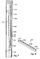
- Figure 6 illustrates an alternative embodiment of the invention wherein the crossover is made of a wear resistant material such as described above.
- the crossover 100 is sheathed with a metal sleeve 122.
- the configuration and function of the crossover 100 is the same.
- the crossover will have at least one exit port 108.
- An abrasive slurry will be delivered through a axial flow passage until it reaches a terminal surface 1 10 which will redirect the slurry through the exit ports 108.
- the metal sleeve protects the crossover from damage during the installation of the crossover into the tool string. Threads on the metal sleeve 122 can be used to couple the crossover to upper and lower connectors 102, 104.
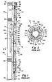
- FIGS 7, 8, 9, and 10 illustrate a crossover 200 also embodying the present invention.
- the crossover 200 uses a mandrel 202 that is shielded with a variety of wear resistant sacrificial elements made of a material like zirconia.
- an insert 204 can be placed in the exit port 206 of the crossover.
- the upper and lower contact surfaces 210, 212 are outwardly declined.
- the area of the exit port 206 decreases from the inner surface of the crossover to its outer surface.
- the insert 204 is placed into the exit port and the pressure of the exiting slurry forces the contact surfaces together and prevents any movement by the insert 204.
- the insert 204 can include a number of flow distribution portals 208.
- portals 208 can vary in order to create a more even pressure gradient across the exit port. For example, if there were only a single portal, the exit slurry pressure would be greater near the bottom of the portal. If two equal portals were used in the insert, the exit slurry pressure would be greater from the lower of the two. Therefore, it is preferable to have portals 208 of decreasing size from the top of the insert to its bottom.
- the insert 204 shown in Figure 8 illustrates the use of several portals, with lowest portal 208a being the smallest. Portals 208b and 208c are progressively larger.
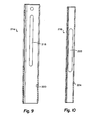
- Figures 9 and 10 illustrate the coaxial outer and inner sacrificial sleeves 214, 216, respectively.
- These sacrificial sleeves 214, 216 can be made of the same material as the insert 204.
- the use of zirconia for theses sacrificial sleeves is an improvement over prior art sleeves made of brass as described in U.S. Patent No. 5,636,691 discussed above.
- the outer sacrificial sleeve 214 has a portal 218 that matches the external dimensions of the exit port 206 on mandrel 202.
- the inner diameter of surface 220 matches the outer diameter of the mandrel 202.
- the inner sacrificial sleeve 216 has a portal 222 that substantially matches the internal dimensions of the exit port 206. Likewise, the outer diameter of surface 224 matches the inner diameter of the mandrel 202. In one embodiment, the wall thickness of either sleeve can be between 0.1 and 0.3 inches (2.54 to 7.62 mm) in thickness. Of course, the anticipated life is extended as the sleeve thickness is increased.
Abstract
Description
- The present invention relates generally to tools used in subterranean wells and, specifically relates to a wear resistant crossover tool used in the delivery of highpressure abrasive slurry in formation fracturing operations.
- Many potentially productive geological formations beneath the earth's surface contain a sufficient volume of valuable fluids, such as hydrocarbons, but production of the fluids is hampered by the low permeability of the formation. "Permeability" is a term used to describe that quality of a geological formation that enables fluids to move about in the formation. All potentially productive formations have pores, a quality described using the term "porosity", within which the valuable fluids are contained. If, however, the pores are not interconnected, the fluids cannot move about and, thus, cannot be brought to the earth's surface.
- When production of a formation having very low permeability, but a sufficient quantity of valuable fluids in its pores is desired, it becomes necessary to artificially increase the formation's permeability. This is typically accomplished by "fracturing" the formation. Fracturing is achieved by applying sufficient pressure to the formation to cause the formation to crack or fracture. The desired result being that the cracks interconnect the formation's pores and allow the valuable fluids to be brought out of the formation and to the surface.
- A conventional method of fracturing a formation begins with drilling a subterranean well into the formation and cementing a protective tubular casing within the well. The casing is then perforated to provide fluid communication between the formation and the interior of the casing that extends to the surface. A packer is set in the casing to isolate the formation from the rest of the wellbore, and hydraulic pressure is applied to the formation via tubing that extends from the packer to pumps on the surface.
- The pumps apply the hydraulic pressure by pumping fracturing fluid down the tubing, through the packer, into the wellbore below the packer, through the perforations, and finally, into the formation. The pressure is increased until the desired quality and quantity of cracks is achieved and maintained. Much research has gone into discerning the precise amount and rate of fracturing fluid and hydraulic pressure to apply to the formation to achieve the desired quality and quantity of cracks.
- Modern fracturing fluids may include sophisticated manmade proppants suspended in gels. "Proppant" is the term used to describe material in the fracturing fluid which enters the formation cracks once formed and while the hydraulic pressure is still being applied (that is, while the cracks are still being held open by the hydraulic pressure), and acts to prop the cracks open. When the hydraulic pressure is removed, the proppant keeps the cracks from closing completely. The proppant thus helps to maintain the artificial permeability of the formation after the fracturing job is over. Fracturing fluid containing suspended proppant is also called slurry.
- A proppant may be nothing more than very fine sand, or it may be a material specifically engineered for the job of holding formation cracks open. Whatever its composition, the proppant must be very hard and strong to withstand the forces trying to close the formation cracks. These qualities also make the proppant a very good abrasive. It is not uncommon for holes to be formed in the protective casing, tubing, pumps, and any other equipment through which slurry is pumped.
- Particularly susceptible to abrasion wear from pumped slurry is any piece of equipment in which the slurry must make a sudden or significant change in direction. Due to its inertia, the slurry tends to maintain its velocity and direction of flow, and resists any change thereof. An object in the flowpath of the slurry that tends to change the velocity or direction of the slurry's flow will soon be worn away as the proppant in the slurry incessantly impinges upon the object. Of particular concern in this regard is the piece of equipment attached to the tubing extending below the packer which takes the slurry as it is pumped down the tubing and redirects it radially outward so that it exits the tubing and enters the formation through the perforations. That piece of equipment is called a Acrossover. Assuming, for purposes of convenience, that the tubing extends vertically through the wellbore, and that the formation is generally horizontal, the crossover must change the direction of the slurry by ninety degrees. Because of this change of direction, the crossover must withstand significant potential abrasive wear.
- One attempt to minimize the wear on the crossover is the use of wear-resistant insert. For example, U.S. Patent No. 5,636,691 discloses the use of a sacrificial tubular insert. Reference is made to Figures 1, 2 and 3 of the present application, which show an abrasive
slurry delivery apparatus 10 similar to that disclosed in the US Patent No. 5,636,691 patent.Apparatus 10 is specially adapted for use within a tool string which is suspended from tubing extending to the earth's surface, the tubing being longitudinally disposed withinprotective casing 2 in a subterranean wellbore. The service tool string is typically inserted through apacker 4 during a fracturing job. Pressurized, abrasive slurry is then pumped through the service tool string. Tubularupper connector 12 andlower connector 14 permit interconnection of theapparatus 10 into the service-tool string. Accordingly,upper portion 16 ofupper connector 12 is connected to the service tool string above theapparatus 10, andlower portion 18 oflower connector 14 is connected to the remainder of the service tool string extending below the apparatus. - An
axial flow passage 20 extends axially downward from theupper portion 16 ofupper connector 12, axially through the upper connector, and into a generallytubular crossover 22. Theaxial flow passage 20 terminates at upper radially reducedportion 24 of generallycylindrical plug 26.Plug 26 is threadedly installed intolower portion 28 ofcrossover 22 and secured with a pair ofset screws 29. Sealing engagement between theplug 26 and thelower portion 28 ofcrossover 22 is provided byseal 30 disposed incircumferential groove 32 externally formed on the plug. - Radially displaced, longitudinally extending,
circulation flow passage 34 extends downwardly fromupper portion 16, through theupper connector 12, longitudinally through thecrossover 22, through thelower connector 14, and tolower portion 18. When operatively installed in awellbore 36, thecirculation flow passage 34 in theapparatus 10 is sealingly isolated from the wellbore external to the apparatus byseal 38 disposed in circumferential groove internally formed on theupper connector 12, and byseal 42 disposed incircumferential groove 44 internally formed on thelower connector 14. Thecirculation flow passage 34 is sealingly isolated fromcoaxial flow passage 20 in theapparatus 10 byseal 30, and by a pair ofseals 46, each disposed in one of a pair of circumferential grooves 48 externally formed on anupper portion 50 of thecrossover 22 which extends coaxially into theupper connector 12. - Annular
antifriction seal rings 52 are disposed in longitudinally spaced apart external annular recesses 54 formed onupper portion 16 ofupper connector 12, betweenupper connector 12 andcrossover 22, and betweencrossover 22 andlower connector 14. Theantifriction seal rings 52 ease insertion and movement of theapparatus 10 within the packer and other equipment into which theapparatus 10 may be longitudinally disposed, as well as providing an effective seal therebetween.Upper portion 50 ofcrossover 22 is threadedly attached toupper connector 12, andlower portion 28 of the crossover is threadedly attached tolower connector 14. - Four longitudinally extending circumferentially spaced apart slotted outlet openings or exit ports 56 (three of which are visible in Figure 1), having external radially extending and circumferentially sloping
surfaces 57 formed thereon, provide fluid communication between theaxial flow passage 20 and thewellbore 36. It is through theseexit ports 56 that a slurry must pass in its transition from longitudinal flow in theaxial flow passage 20 to radial flow into thewellbore 36. Because of the substantial change of direction from longitudinal flow to radial flow of the slurry through theexit ports 56, the exit ports are particularly susceptible to abrasion wear from proppant contained in the slurry. - In order to protect the
exit ports 56 against abrasion wear, a tubularprotective sleeve 58 is coaxially disposed within thecrossover 22. Theprotective sleeve 58 is made of a suitably hard and tough abrasion resistant material, such as tungsten carbide, or is made of a material, such as alloy steel, which has been hardened. If made of an alloy steel, theprotective sleeve 58 is preferably through-hardened by a process such as case carburizing or nitriding. Other materials and hardening methods may be employed for theprotective sleeve 58 without deviating from the principles of the present invention. Tests performed by the applicants indicate that theprotective sleeve 58 is preferably made of tungsten carbide. - The
protective sleeve 58 is secured into thecrossover 22 bydrive pin 60 that extends laterally through the protective sleeve and theupper portion 24 of theplug 26.Outer diameter 62 ofprotective sleeve 58 is only slightly smaller thaninner diameter 64 ofcrossover 22 to prevent the slurry from flowing between the protective sleeve and the crossover. Alternatively, theprotective sleeve 58outer diameter 62 may be slightly larger than thecrossover 22inner diameter 64 such that a press fit or shrink fit is obtained between them. -
Upper portion 66 ofprotective sleeve 58 extends axially upward past theexit ports 56 in thecrossover 22, thereby completely internally overlapping that portion of thecrossover 22 in which theexit ports 56 are located. Internal longitudinally extending and radially slopingtransition surface 68 formed in theupper portion 66 ofprotective sleeve 58 provides a smooth transition between theinner diameter 64 in theupper portion 50 of thecrossover 22 and radially reducedinner diameter 70 of theprotective sleeve 58. Note thattransition surface 68 extends radially opposite and longitudinally acrossupper end surfaces 72 ofexit ports 56. - Four longitudinally extending and circumferentially spaced slotted outlet openings or
flow ports 74 formed in theprotective sleeve 58 are circumferentially aligned with theexit ports 56 in thecrossover 22.Flow ports 74 are each slightly smaller in length and width thanexit ports 56. Thus, flowports 74 do not permit direct impingement of the slurry on thecrossover 22 as it flows radially from theaxial flow passage 20 and into thewellbore 36. - Coaxially disposed within the
protective sleeve 58 is a tubularsacrificial insert 76. Theinsert 76 is secured to theupper portion 24 of theplug 26 radially intermediate the plug and theprotective sleeve 58. Theinsert 76 extends longitudinally upward from theplug 26 to a location somewhat downward fromtransition surface 68 of theprotective sleeve 58. An upwardly opening interior hollow cylindrical volume within theinsert 76 above theupper portion 24 of theplug 26 forms aslurry well 78. An internal longitudinally extending and radially slopedtransition surface 80 formed in anupper portion 82 of theinsert 76 smooths the transition between theinner diameter 70 of theprotective sleeve 58 toinner diameter 84 of the insert. As the slurry flows longitudinally downward through thecoaxial flow passage 20 into thecrossover 22, the slurry will enter the well 78 through its upwardly facing openupper portion 82 and quickly fill the well. Thereafter, the downwardly flowing slurry will directly impinge on the portion of the slurry which has filled the well 78, effectively preventing the slurry from abrading any portion of thecrossover 22,protective sleeve 58, or insert 76 due to direct longitudinal impingement by the slurry. - However, as the slurry flow changes direction from longitudinal to radial near the
upper portion 82 of theinsert 76, abrasion from the slurry flow will gradually wear away the insert. This wearing away of theinsert 76 is intended, and the material of which the insert is made is selected to regulate the rate at which the insert wears away. For most applications, theinsert 76 is preferably made of brass. Theinsert 76 may also be made of a more easily abraded material such as aluminum, or a less easily abraded material such as mild steel, to regulate its wear rate without deviating from the principles of the present invention. Preferably, the material of which theinsert 76 is made should be selected such that the insert wears longitudinally downward, gradually exposing more of theprotective sleeve 58 to the radially directed flow of the slurry, such that theflow ports 74 of theprotective sleeve 58 are not permitted to wear circumferentially outward sufficiently far to expose theexit ports 56 of thecrossover 22 to the radially directed flow of the slurry. - The
flow ports 74 of theprotective sleeve 58 wear at a greater rate at a portion of theflow ports 74 exposed to the radially directed slurry flow that is most longitudinally downward. Thus,portions 86 of theprotective sleeve 58 will have the greatest rate of wear. This is becauseportions 86 are the portions of theprotective sleeve 58 exposed to the radially directed slurry flow which are most longitudinally downward disposed. - With longitudinally extending and circumferentially spaced apart slotted ports such as the
flow ports 74 in theprotective sleeve 58, the highwear rate portions 86 extend longitudinally approximately 1.5 inches (38.1 mm). For this reason,upper edge 88 of theinsert 76 is longitudinally spaced downward from thetransition surface 68 on theprotective sleeve 58 approximately 1.5 inches (38.1 mm), thereby preventing excessive wear of the transition surface 68 (where radial thickness of theprotective sleeve 58 is minimal) andupper portion 66 of the protective sleeve. The longitudinal extent of highwear rate portions 86 may vary depending on factors such as slurry flow rate and flowport 74 width and number of flow ports. The longitudinal distance between theupper edge 88 of theinsert 76 and thetransitional surface 68 of theprotective sleeve 58 may be varied without deviating from the principles of the present invention. - The
insert 76 acts to effectively "spread" the circumferential wear of theflow ports 74 longitudinally downward as theinsert 76 wears longitudinally downward within theprotective sleeve 58. This is due to the fact that as theinsert 76 wears longitudinally downward a gradually increasingly downward portion of theflow ports 74 is exposed to the radially directed slurry flow. In other words, highwear rate portions 86 gradually move longitudinally downward asinsert 76 wears longitudinally downward. This unique interaction of theinsert 76 with theprotective sleeve 58 acts to prolong the useful life of the protective sleeve. - Turning now to Figure 2, a cross-sectional view may be seen of the
apparatus 10 representatively illustrated in Figure 1. The cross-section is taken through line 2-2 of Figure 1 that extends laterally through thecrossover 22. In this view, the manner in whichcirculation flow passage 34 extends longitudinally through thecrossover 22 may be seen. Eight longitudinally extending and circumferentially spacedcirculation ports 90 are disposed radially intermediate theinner diameter 64 of thecrossover 22 andouter diameter 92 of the crossover. Two each of thecirculation ports 90 are disposed in thecrossover 22 circumferentially intermediate each pair ofexit ports 56. Note that various quantities and locations may be chosen for thecirculation ports 90 and theexit ports 56 in thecrossover 22. - Figure 2 also illustrates the necessity for preventing abrasion wear of the
crossover 22. Ifexit ports 56 are allowed to wear appreciably circumferentially outward, theexit ports 56 will eventually be in fluid communication with thecirculation ports 90. It may also be clearly seen in Figure 2 that flowports 74 inprotective sleeve 58, being somewhat smaller in width than theexit ports 56, act to protect theexit ports 56 from abrasion wear due to radially outwardly directed flow of the slurry. Note that in this viewprotective sleeve 58 and insert 76 each completely internally overlap theinner diameter 64 of thecrossover 22. Thus, thecrossover 22 is not only protected against circumferentially outward wear of itsexit ports 56, it is also protected against radially outward wear of itsinner diameter 64. - Figure 3 illustrates the use of a blast joint 90 to protect
casing 2. The radial flow from the crossover can damage thecasing 2. Therefore, the blast joint 90 redirects the flow from theexit ports 56 of thecrossover 10. The blast joint 90 acts as a shield and endures the full force of the abrasive slurry. Often, asacrificial liner 92 is placed on the impact surface. The redirected slurry passes throughports 96 in the blast joint 90 and enters thewell annulus 6. From there, the abrasive slurry can pass into the formation throughperforations 8 in thecasing 2. One problem observed with the use of blast joints is the exterior wear produced on the crossover. In other words, the radial flow of slurry from the crossover strikes the blast joint 90 and rebounds against the exterior surface of the crossover, below the ports 54. - It would be desirable to provide a crossover tool that can better withstand the abrasion from a high pressure slurry. Such a material should be suitable for use as a sacrificial insert in the exit ports, the interior surface, or the exterior surface of the crossover. Alternatively, a need exists for a material that can be used to form the entire crossover.
- The present invention relates to a highly wear resistant crossover tool made of a ceramic material such as zirconia. Zirconia is a trade name for a material that is approximately 96% zirconium oxide and approximately 4% magnesium oxide. Zirconia has been found to have superior wear resistance. Further, zirconia can be machined into a variety of shapes. Zirconia has a melting point of approximately 5000°F (2760°C) and a specific gravity of between approximately 5.6 and 6.0. It is available from manufacturers such as Coors Ceramics Company of Golden, Colorado. Zirconia is chemically inert. In other words, there are no known conditions causing instability. It demonstrates a tensile strength of approximately 352 MPa and a hardness of between 11.8 and 12.7 GPa (as measured by the Knoop 1000g hardness test). These properties compare favorably to the steel used in existing crossovers. Other materials could include zinc oxide, tungsten carbide, various composites and other fired materials.
- In another embodiment, a ceramic crossover is used with a metal outer sleeve. The sleeve can include the necessary threading to connect the crossover assembly to other tool string elements. In another embodiment, a steel crossover is shielded with ceramic wear elements. For example, the axial ports can include inserts that endure the abrasive force of the fracturing fluid. Inner and outer protective sleeves can also be used to protect the inner and outer surfaces of the crossover. In certain circumstances, the well casing is protected from the abrasive effects by a blast joint. The blast joint is suspended around the crossover and redirects the abrasive slurry to an entry point into the formation. When blast joints are used, the reflected slurry can abrade the outer surface of the crossover. Thus, an outer sleeve can lengthen the useful life of the crossover.
- According to one aspect of the invention there is provided a wear resistant crossover comprising a generally tubular element having an axial passage therethrough, and at least one exit port located through an axial wall of said crossover, wherein said crossover is made of a material including a ceramic.
- In an embodiment, the crossover further comprises a plug having a terminal surface across said axial passage.
- In an embodiment, the or each exit port comprises a sloped surface.
- In an embodiment, the or each exit port comprises an upper surface substantially perpendicular to the axial wall of the crossover.
- Preferably, the ceramic includes zirconium oxide.
- In an embodiment, the crossover further comprises at least one annularly located circulation port.
- In an embodiment, the crossover further comprises an outer metal sleeve.
- According to another aspect of the invention there is provided a wear resistant crossover comprising: a generally tubular mandrel having an axial passage therethrough, and inner surface and an outer surface; at least one exit port located through an axial wall of said crossover; and at least one sacrificial insert coupled to said crossover, wherein said sacrificial insert is composed of a wear resistant material including a ceramic.
- In an embodiment, the or each sacrificial insert comprises an insert dimensioned to fit within the at least one exit port. The insert may comprise a solid member having a plurality of portals therethrough. The insert may comprise an upper and lower contact surface, and at least one of said contact surfaces may be sloped. The crossover insert portals may comprise a plurality of holes of increasing area.
- In an embodiment, the or each sacrificial insert comprises an inner sleeve dimensioned to fit against an inner surface of the mandrel.
- In an embodiment, the or each sacrificial insert comprises an outer sleeve dimensioned to fit against the outer surface of the mandrel.
- In an embodiment, said mandrel further comprises at least one circulation flow passage.
- According to another aspect of the invention there is provided a wear resistant insert for use with a crossover comprising a sacrificial member made of a ceramic.
- The sacrificial member may be dimensioned to fit into an exit port of the crossover. The sacrificial member may be an inner sleeve or an outer sleeve.
- Reference is now made to the accompanying drawings, in which:
- Figure 1 is a partially cross-sectional view of a prior art slurry delivery apparatus having a crossover, a tubular protective sleeve, and a tubular sacrificial insert therein which can be made in accordance with the present invention;
- Figure 2 is an enlarged scale cross-sectional view of the crossover of the slurry delivery apparatus, taken along line 2-2 of Figure 1 ;
- Figure 3 is a sectional across a crossover and a surrounding blast joint;
- Figure 4 is a cross-sectional view across the length of an embodiment of a crossover tool according to the present invention;
- Figure 5 is a cross-sectional across the axis of the crossover tool shown in Figure 4;
- Figure 6 illustrates a ceramic crossover having a metal outer sleeve; and
- Figures 7, 8, 9, and 10 illustrate a crossover with ceramic wear elements in the axial ports, and along the inner and outer diameters.
-
- Figures 4 and 5 illustrate a first embodiment of an all
ceramic crossover 100 which embodies the present invention. Thecrossover 100 is connected to a tool string by itsupper connector 102. The service tool string is typically inserted through a packer during a fracturing job. A pressurized, abrasive slurry is then pumped into the service tool string. Tubularupper connector 102 andlower connector 104 permit interconnection of thecrossover 100 into the service tool string.Axial flow passage 106 extends downward through the crossover from theupper connector 102. Theaxial flow passage 106 terminates at theterminal surface 110. Theterminal surface 110 can be any shape, but in one embodiment is a generally conical shape. Theterminal surface 110 can be an integral part of the crossover or alternatively, can be part of aplug 111 coupled to the crossover. When the slurry is pumped through theaxial passage 106, it impacts upon thetermination surface 110, and is redirected through at least oneexit port 108. In the embodiment illustrated, threeexit ports 108 are used. The redirected slurry impacts against the walls of the formation to enhance its permeability and to deliver proppant to maintain the improved permeability. - To better understand the size of the invention, a
typical crossover 100 could be between ten and eighteen inches (0.254 to 0.457 m) in length. Theports 108 could be between six and nine inches in length (0.152 to 0.229 m). A wall thickness of the crossover might be between one-half to two inches (12.7 to 50.8 mm). Theexit ports 108 can be any suitable shape, but in a preferred embodiment, are generally oval. Theports 108 have both anupper surface 108a and alower surface 108b. Theupper surface 108a is generally perpendicular to the inner and outeraxial walls lower surface 108b can have a downwardly angled slope as shown. The slope ofsurface 108b prevents direct impingement of the slurry against its surface. - After a formation is fractured, the valuable fluids therein flow into the annulus of the wellbore. The fluids then enter the relatively low pressure of the
circulation flow passages 116 shown best in Figure 5. The reservoir's fluid must be brought back to the surface. Thecirculation flow passages 116 pass axially through the body of thecrossover 100. Any number of circulation flow passages can be formed in the crossover. Three sets of three are shown in the illustrated embodiment. - The
crossover 100 is preferably made of Azirconia, a material that can be between 85% to 100% zirconium oxide with the remainder being magnesium oxide. Zirconia has been found to have superior wear resistance. Further, zirconia can be machined into a variety of shapes. Zirconia has a melting point of approximately 5000°F (2760°C) and a specific gravity of between approximately 5.6 and 6.0. These properties compare favorably to the steel used in existing crossovers. - Figure 6 illustrates an alternative embodiment of the invention wherein the crossover is made of a wear resistant material such as described above. However, the
crossover 100 is sheathed with ametal sleeve 122. In other ways, the configuration and function of thecrossover 100 is the same. For example, the crossover will have at least oneexit port 108. An abrasive slurry will be delivered through a axial flow passage until it reaches a terminal surface 1 10 which will redirect the slurry through theexit ports 108. The metal sleeve protects the crossover from damage during the installation of the crossover into the tool string. Threads on themetal sleeve 122 can be used to couple the crossover to upper andlower connectors - Figures 7, 8, 9, and 10 illustrate a crossover 200 also embodying the present invention. The crossover 200 uses a
mandrel 202 that is shielded with a variety of wear resistant sacrificial elements made of a material like zirconia. For example, aninsert 204 can be placed in theexit port 206 of the crossover. To ensure that theinsert 204 remains in the exit ports, the upper and lower contact surfaces 210, 212 are outwardly declined. In other words, the area of theexit port 206 decreases from the inner surface of the crossover to its outer surface. Theinsert 204 is placed into the exit port and the pressure of the exiting slurry forces the contact surfaces together and prevents any movement by theinsert 204. Theinsert 204 can include a number of flow distribution portals 208. These portals 208 can vary in order to create a more even pressure gradient across the exit port. For example, if there were only a single portal, the exit slurry pressure would be greater near the bottom of the portal. If two equal portals were used in the insert, the exit slurry pressure would be greater from the lower of the two. Therefore, it is preferable to have portals 208 of decreasing size from the top of the insert to its bottom. Theinsert 204 shown in Figure 8 illustrates the use of several portals, with lowest portal 208a being the smallest.Portals - Figures 9 and 10 illustrate the coaxial outer and inner
sacrificial sleeves sacrificial sleeves insert 204. For example, the use of zirconia for theses sacrificial sleeves is an improvement over prior art sleeves made of brass as described in U.S. Patent No. 5,636,691 discussed above. The outersacrificial sleeve 214 has a portal 218 that matches the external dimensions of theexit port 206 onmandrel 202. Likewise, the inner diameter ofsurface 220 matches the outer diameter of themandrel 202. The innersacrificial sleeve 216 has a portal 222 that substantially matches the internal dimensions of theexit port 206. Likewise, the outer diameter ofsurface 224 matches the inner diameter of themandrel 202. In one embodiment, the wall thickness of either sleeve can be between 0.1 and 0.3 inches (2.54 to 7.62 mm) in thickness. Of course, the anticipated life is extended as the sleeve thickness is increased. - It will be appreciated that the invention described above may be modified.
Claims (10)
- A wear resistant crossover comprising a generally tubular element having an axial passage therethrough, and at least one exit port located through an axial wall of 5 said crossover, wherein said crossover is made of a material including a ceramic.
- A crossover according to Claim 1, further comprising a plug having a terminal surface across said axial passage.
- A crossover according to Claim 1 or 2, wherein the or each exit port comprises a sloped surface.
- A crossover according to Claim 1 or 2, wherein the or each exit port comprises an upper surface substantially perpendicular to the axial wall of the crossover.
- A wear resistant crossover comprising: a generally tubular mandrel having an axial passage therethrough, and an inner surface and an outer surface; at least one exit port located through an axial wall of said crossover; and at least one sacrificial insert coupled to said crossover, wherein said sacrificial insert is composed of a wear 20 resistant material including a ceramic.
- A crossover according to Claim 5, wherein the or each sacrificial insert comprises an insert dimensioned to fit within the at least one exit port.
- A crossover according to Claim 6, wherein the insert comprises a solid member having a plurality of portals therethrough.
- A crossover according to Claim 6 or 7, wherein said insert comprises an upper and lower contact surface, wherein at least one of said contact surfaces is sloped.
- A wear resistant insert for use with a crossover, comprising a sacrificial member made of a ceramic.
- An insert according to Claim 9, wherein said ceramic includes a zirconium oxide.
Applications Claiming Priority (2)
| Application Number | Priority Date | Filing Date | Title |
|---|---|---|---|
| US1892298A | 1998-02-05 | 1998-02-05 | |
| US18922 | 1998-02-05 |
Publications (2)
| Publication Number | Publication Date |
|---|---|
| EP0935050A2 true EP0935050A2 (en) | 1999-08-11 |
| EP0935050A3 EP0935050A3 (en) | 2001-05-16 |
Family
ID=21790439
Family Applications (1)
| Application Number | Title | Priority Date | Filing Date |
|---|---|---|---|
| EP99300812A Withdrawn EP0935050A3 (en) | 1998-02-05 | 1999-02-03 | Wear resistant crossover |
Country Status (1)
| Country | Link |
|---|---|
| EP (1) | EP0935050A3 (en) |
Cited By (8)
| Publication number | Priority date | Publication date | Assignee | Title |
|---|---|---|---|---|
| WO2001040614A2 (en) * | 1999-11-30 | 2001-06-07 | Carpenter Advanced Ceramics, Inc. | Ceramic components for high pressure oil wells |
| GB2370054A (en) * | 2000-12-14 | 2002-06-19 | Halliburton Energy Serv Inc | Abrasive slurry delivery apparatus |
| US6892818B2 (en) | 2000-11-28 | 2005-05-17 | Carpenter Advanced Ceramics, Inc. | Interchangeable choke assembly |
| WO2010045074A2 (en) * | 2008-10-13 | 2010-04-22 | Baker Hughes Incorporated | Crossover sub with erosion resistant inserts |
| WO2014172048A1 (en) * | 2013-04-15 | 2014-10-23 | Halliburton Energy Services, Inc. | Anti wear device for composite packers and plugs |
| US9097104B2 (en) | 2011-11-09 | 2015-08-04 | Weatherford Technology Holdings, Llc | Erosion resistant flow nozzle for downhole tool |
| US9677383B2 (en) | 2013-02-28 | 2017-06-13 | Weatherford Technology Holdings, Llc | Erosion ports for shunt tubes |
| US10947823B2 (en) | 2017-08-03 | 2021-03-16 | Halliburton Energy Services, Inc. | Erosive slurry diverter |
Citations (1)
| Publication number | Priority date | Publication date | Assignee | Title |
|---|---|---|---|---|
| US5636691A (en) | 1995-09-18 | 1997-06-10 | Halliburton Energy Services, Inc. | Abrasive slurry delivery apparatus and methods of using same |
Family Cites Families (2)
| Publication number | Priority date | Publication date | Assignee | Title |
|---|---|---|---|---|
| US4765205A (en) * | 1987-06-01 | 1988-08-23 | Bob Higdon | Method of assembling drill bits and product assembled thereby |
| US5842516A (en) * | 1997-04-04 | 1998-12-01 | Mobil Oil Corporation | Erosion-resistant inserts for fluid outlets in a well tool and method for installing same |
-
1999
- 1999-02-03 EP EP99300812A patent/EP0935050A3/en not_active Withdrawn
Patent Citations (1)
| Publication number | Priority date | Publication date | Assignee | Title |
|---|---|---|---|---|
| US5636691A (en) | 1995-09-18 | 1997-06-10 | Halliburton Energy Services, Inc. | Abrasive slurry delivery apparatus and methods of using same |
Cited By (14)
| Publication number | Priority date | Publication date | Assignee | Title |
|---|---|---|---|---|
| WO2001040614A3 (en) * | 1999-11-30 | 2002-01-31 | Carpenter Advanced Ceramics In | Ceramic components for high pressure oil wells |
| US6367546B1 (en) | 1999-11-30 | 2002-04-09 | Carpenter Advanced Ceramics, Inc. | Ceramic components for high pressure oil wells |
| WO2001040614A2 (en) * | 1999-11-30 | 2001-06-07 | Carpenter Advanced Ceramics, Inc. | Ceramic components for high pressure oil wells |
| US6892818B2 (en) | 2000-11-28 | 2005-05-17 | Carpenter Advanced Ceramics, Inc. | Interchangeable choke assembly |
| GB2370054A (en) * | 2000-12-14 | 2002-06-19 | Halliburton Energy Serv Inc | Abrasive slurry delivery apparatus |
| GB2370054B (en) * | 2000-12-14 | 2004-12-15 | Halliburton Energy Serv Inc | Improved abrasive slurry delivery apparatus and methods of using same |
| US6491097B1 (en) | 2000-12-14 | 2002-12-10 | Halliburton Energy Services, Inc. | Abrasive slurry delivery apparatus and methods of using same |
| US8371369B2 (en) | 2007-12-04 | 2013-02-12 | Baker Hughes Incorporated | Crossover sub with erosion resistant inserts |
| WO2010045074A2 (en) * | 2008-10-13 | 2010-04-22 | Baker Hughes Incorporated | Crossover sub with erosion resistant inserts |
| WO2010045074A3 (en) * | 2008-10-13 | 2010-07-29 | Baker Hughes Incorporated | Crossover sub with erosion resistant inserts |
| US9097104B2 (en) | 2011-11-09 | 2015-08-04 | Weatherford Technology Holdings, Llc | Erosion resistant flow nozzle for downhole tool |
| US9677383B2 (en) | 2013-02-28 | 2017-06-13 | Weatherford Technology Holdings, Llc | Erosion ports for shunt tubes |
| WO2014172048A1 (en) * | 2013-04-15 | 2014-10-23 | Halliburton Energy Services, Inc. | Anti wear device for composite packers and plugs |
| US10947823B2 (en) | 2017-08-03 | 2021-03-16 | Halliburton Energy Services, Inc. | Erosive slurry diverter |
Also Published As
| Publication number | Publication date |
|---|---|
| EP0935050A3 (en) | 2001-05-16 |
Similar Documents
| Publication | Publication Date | Title |
|---|---|---|
| EP0789131B1 (en) | Downhole abrasive slurry delivery apparatus | |
| US6155342A (en) | Proppant containment apparatus | |
| US9835003B2 (en) | Frac plug | |
| US6491097B1 (en) | Abrasive slurry delivery apparatus and methods of using same | |
| US6575247B2 (en) | Device and method for injecting fluids into a wellbore | |
| US6394180B1 (en) | Frac plug with caged ball | |
| US7044221B2 (en) | Apparatus for coupling a tubular member to a preexisting structure | |
| CA3016153A1 (en) | Frac plug | |
| US10125553B2 (en) | Coring tools for managing hydraulic properties of drilling fluid and related methods | |
| US20100122817A1 (en) | Apparatus and method for servicing a wellbore | |
| CA3124339C (en) | Downhole disconnect tool | |
| US11434715B2 (en) | Frac plug with collapsible plug body having integral wedge and slip elements | |
| EP0935050A2 (en) | Wear resistant crossover | |
| US7131497B2 (en) | Articulated drillstring entry apparatus and method | |
| GB2385358A (en) | Apparatus for radially expanding a tubular member | |
| US5924487A (en) | Proppant slurry screen apparatus and methods of using same | |
| US10465478B2 (en) | Toe valve | |
| US11220868B2 (en) | Split threads for fixing accessories to a body | |
| US20130048306A1 (en) | Apparatus and method for penetrating cement surrounding a tubular | |
| US11702904B1 (en) | Toe valve having integral valve body sub and sleeve | |
| CA2132458A1 (en) | Multi- port oilfield liner connector | |
| CA2751135C (en) | Apparatus and method for penetrating cement surrounding a tubular | |
| EP2565372A1 (en) | Apparatus and method for penetrating cement surrounding a tubular |
Legal Events
| Date | Code | Title | Description |
|---|---|---|---|
| PUAI | Public reference made under article 153(3) epc to a published international application that has entered the european phase |
Free format text: ORIGINAL CODE: 0009012 |
|
| AK | Designated contracting states |
Kind code of ref document: A2 Designated state(s): AT BE CH CY DE DK ES FI FR GB GR IE IT LI LU MC NL PT SE |
|
| AX | Request for extension of the european patent |
Free format text: AL;LT;LV;MK;RO;SI |
|
| PUAL | Search report despatched |
Free format text: ORIGINAL CODE: 0009013 |
|
| AK | Designated contracting states |
Kind code of ref document: A3 Designated state(s): AT BE CH CY DE DK ES FI FR GB GR IE IT LI LU MC NL PT SE |
|
| AX | Request for extension of the european patent |
Free format text: AL;LT;LV;MK;RO;SI |
|
| RIC1 | Information provided on ipc code assigned before grant |
Free format text: 7E 21B 17/10 A, 7E 21B 43/26 B |
|
| AKX | Designation fees paid | ||
| STAA | Information on the status of an ep patent application or granted ep patent |
Free format text: STATUS: THE APPLICATION IS DEEMED TO BE WITHDRAWN |
|
| REG | Reference to a national code |
Ref country code: DE Ref legal event code: 8566 |
|
| 18D | Application deemed to be withdrawn |
Effective date: 20011117 |