EP0936514A2 - Method and device for controlling the drive system of a machine and/or an installation - Google Patents
Method and device for controlling the drive system of a machine and/or an installation Download PDFInfo
- Publication number
- EP0936514A2 EP0936514A2 EP99100321A EP99100321A EP0936514A2 EP 0936514 A2 EP0936514 A2 EP 0936514A2 EP 99100321 A EP99100321 A EP 99100321A EP 99100321 A EP99100321 A EP 99100321A EP 0936514 A2 EP0936514 A2 EP 0936514A2
- Authority
- EP
- European Patent Office
- Prior art keywords
- control
- drive system
- measurement data
- calculation system
- control loop
- Prior art date
- Legal status (The legal status is an assumption and is not a legal conclusion. Google has not performed a legal analysis and makes no representation as to the accuracy of the status listed.)
- Granted
Links
Images

Classifications
-
- G—PHYSICS
- G05—CONTROLLING; REGULATING
- G05B—CONTROL OR REGULATING SYSTEMS IN GENERAL; FUNCTIONAL ELEMENTS OF SUCH SYSTEMS; MONITORING OR TESTING ARRANGEMENTS FOR SUCH SYSTEMS OR ELEMENTS
- G05B13/00—Adaptive control systems, i.e. systems automatically adjusting themselves to have a performance which is optimum according to some preassigned criterion
- G05B13/02—Adaptive control systems, i.e. systems automatically adjusting themselves to have a performance which is optimum according to some preassigned criterion electric
- G05B13/0265—Adaptive control systems, i.e. systems automatically adjusting themselves to have a performance which is optimum according to some preassigned criterion electric the criterion being a learning criterion
- G05B13/0295—Adaptive control systems, i.e. systems automatically adjusting themselves to have a performance which is optimum according to some preassigned criterion electric the criterion being a learning criterion using fuzzy logic and expert systems
-
- B—PERFORMING OPERATIONS; TRANSPORTING
- B60—VEHICLES IN GENERAL
- B60W—CONJOINT CONTROL OF VEHICLE SUB-UNITS OF DIFFERENT TYPE OR DIFFERENT FUNCTION; CONTROL SYSTEMS SPECIALLY ADAPTED FOR HYBRID VEHICLES; ROAD VEHICLE DRIVE CONTROL SYSTEMS FOR PURPOSES NOT RELATED TO THE CONTROL OF A PARTICULAR SUB-UNIT
- B60W50/00—Details of control systems for road vehicle drive control not related to the control of a particular sub-unit, e.g. process diagnostic or vehicle driver interfaces
- B60W2050/0001—Details of the control system
- B60W2050/0043—Signal treatments, identification of variables or parameters, parameter estimation or state estimation
- B60W2050/0057—Frequency analysis, spectral techniques or transforms
-
- F—MECHANICAL ENGINEERING; LIGHTING; HEATING; WEAPONS; BLASTING
- F16—ENGINEERING ELEMENTS AND UNITS; GENERAL MEASURES FOR PRODUCING AND MAINTAINING EFFECTIVE FUNCTIONING OF MACHINES OR INSTALLATIONS; THERMAL INSULATION IN GENERAL
- F16H—GEARING
- F16H61/00—Control functions within control units of change-speed- or reversing-gearings for conveying rotary motion ; Control of exclusively fluid gearing, friction gearing, gearings with endless flexible members or other particular types of gearing
- F16H2061/0075—Control functions within control units of change-speed- or reversing-gearings for conveying rotary motion ; Control of exclusively fluid gearing, friction gearing, gearings with endless flexible members or other particular types of gearing characterised by a particular control method
- F16H2061/0081—Fuzzy logic
-
- F—MECHANICAL ENGINEERING; LIGHTING; HEATING; WEAPONS; BLASTING
- F16—ENGINEERING ELEMENTS AND UNITS; GENERAL MEASURES FOR PRODUCING AND MAINTAINING EFFECTIVE FUNCTIONING OF MACHINES OR INSTALLATIONS; THERMAL INSULATION IN GENERAL
- F16H—GEARING
- F16H61/00—Control functions within control units of change-speed- or reversing-gearings for conveying rotary motion ; Control of exclusively fluid gearing, friction gearing, gearings with endless flexible members or other particular types of gearing
- F16H2061/0075—Control functions within control units of change-speed- or reversing-gearings for conveying rotary motion ; Control of exclusively fluid gearing, friction gearing, gearings with endless flexible members or other particular types of gearing characterised by a particular control method
- F16H2061/0084—Neural networks
-
- F—MECHANICAL ENGINEERING; LIGHTING; HEATING; WEAPONS; BLASTING
- F16—ENGINEERING ELEMENTS AND UNITS; GENERAL MEASURES FOR PRODUCING AND MAINTAINING EFFECTIVE FUNCTIONING OF MACHINES OR INSTALLATIONS; THERMAL INSULATION IN GENERAL
- F16H—GEARING
- F16H61/00—Control functions within control units of change-speed- or reversing-gearings for conveying rotary motion ; Control of exclusively fluid gearing, friction gearing, gearings with endless flexible members or other particular types of gearing
- F16H2061/0075—Control functions within control units of change-speed- or reversing-gearings for conveying rotary motion ; Control of exclusively fluid gearing, friction gearing, gearings with endless flexible members or other particular types of gearing characterised by a particular control method
- F16H2061/0087—Adaptive control, e.g. the control parameters adapted by learning
Definitions
- the invention relates to a method for controlling a Drive system of a machine and / or a system according to the The preamble of claim 1 and a device for Implementation of such a procedure.
- DE 38 15 530 C2 describes a control method that is useful for monitoring to determine the speed of one with a drive system connected machine, such as the drive motor Printing machine, known in which the speed by means of a Speed sensor detected and with a predetermined for the drive system Setpoint is compared.
- the setpoint becomes one mathematical model one by the drive system and the Machine formed controlled system fed to its output provides a calculated actual value, which for control and Control purposes is compared with the measured actual value.
- the Speed sensor is preferably designed with an incremental encoder, which is used to generate countable speedometer signals, which are fed to a control unit of the machine.
- DE 43 33 286 A1 describes a for diagnosing faults in Processes designed for machines, such as a punch press known in which a computer system is used, the one Expert system and a separate one, the saving of Knowledge database contains useful data.
- the expert system will doing so for the purpose of identifying malfunctions Processing of rule information used for the implementation of operational processes of the machine and with the Knowledge data of the database depending on initial commands be made available, which result from the information of a Controller or controller of the machine.
- DE 44 33 593 A1 describes a method for regulating a machine, such as one in the production of food used extruder, known, in which the data from setpoint specifications based on experimental data and / or expert knowledge created and control variables of the control depend on subjective judgments one sensory, for example by means of a viscosity sensor or analytically monitored product quality.
- setpoint specifications a working point of each machine is optimized and stabilized, and continues to be a part of the machine control integrated controller created.
- Fuzzy controllers are provided, individually to the product-specific Manipulated variables of these control sections are adjusted.
- DE 195 27 323 A1 describes a circuit arrangement for controlling a device used to detect a driving situation in a motor vehicle known in which an evaluation of Sensor signals and the generation of control signals useful Fuzzy system is connected to a neural network.
- the sensor signals with reference data for compared the driving of the vehicle for optimization of the fuzzy system to provide control signals that a control of the driving operation depending on the current driving situation allow the vehicle.
- plant For controlling a drive system of a machine and / or one Conceptually, plant can have minimum and maximum boundary conditions for the design of a control loop in question be taken into account with model tests of a measuring drive, however, it is difficult to get one in the actual work occurring disturbance behavior for a possibly as necessary to determine the considered correction of the regulation in particular if the type of disturbance is unknown.
- mainly Multi-size arrangements are offered that have a simultaneous presence result from several controlled variables. It can be used accordingly Corrected control signals to an actuator due to parameters supplied with the machine, which is in one with a Data acquisition in a closed system trained in a calculation system Control loop is integrated.
- the invention has for its object a method for Controlling a drive system of a machine and / or a system To provide, which is a rapid automatic Adaptation to changing operating conditions results in have their cause in a malfunction of the drive system.
- the method according to the invention results as a result of the intended adaptive parameter control of the control loop one extremely stable regulation even without the need for a permanent Target-actual comparison also for such applications, where a possible malfunction of the drive system is not planned. For example, irregular or more frequently changing and / or excessive load surges and torque surges for small drives in be excluded as a rule, so with such small drives Suitable precautions have so far been lacking in order to ensure to master conditional disturbance behavior in terms of control technology.
- the intended adaptive parameter control of the control loop So a self-learning optimization of the rule base exclusively obtained via the control loop's own parameters without that impulses from outside are needed for this, because through that for the parameter control used neural network generation can be ensured by its own control parameters.
- the overall concept of the control method according to the invention is therefore an automatically changing rule structure with every adjustment receive a changing rule parameter as soon as this change based on abnormal or ambiguous detectable measurement data is made. But it can a control procedure can also be designed that is suitable for a suitable for a wider range of machine drive systems where the boundary conditions for a control loop are further apart, without it being necessary, individual requirements for different operating parameters.
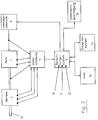
- Fig. 1 is for an embodiment the invention an electronically commutated electric motor 1 with a directly flanged gear 2 is taken into account.
- a Drive system referred to in its entirety as a geared motor results in an optimization of efficiency and freedom from wear and allows a high torque stability reach different speeds.
- the actual value measurement data taken from the individual sensors for the motor 1 and the transmission 2 are fed to a data acquisition 7, in which they are converted into digital parameters that thus correspond to certain operating states.
- the data acquisition is connected to a calculation system 8, which by Setpoints of the measurement data provided by algorithms contains and thus parameter-related corrected control signals to an actuator can deliver that with power electronics 9 for the Motor 1 is designed and thus in one with the data acquisition 7 and the closed loop control system 8 is integrated.
- the calculation system 8 contains as a first rule base Control circuit a classic adaptive controller 10 and as one second rule base a fuzzy controller 11, both with one self-learning system based on a neural network 12 are linked.
- a classic adaptive controller 10 the boundary conditions relevant for the drive system are regulated.
- the fuzzy controller 11 on the other hand, all are considered disturbance variables possibly occurring abnormal or ambiguous detectable measurement data recorded, so by linking with the neural network 12 an adaptive parameter control of the Control loop can be created.
- an evolution strategy be used, which should make it possible for everyone for example as a result of a momentarily excessive load surge or as Consequence of a momentarily excessive torque surge, removed from the gear shaft 15 of the drive system, once or also repeatedly appearing disturbance variable in a with the calculation system 8 connected expert system 14 to take over with this takeover, an optimization of the Calculation system based on a disturbance variable to get adjusted new control parameters It is then ensures that on the basis of a modified accordingly Rule structure of every repetitive analog repetition in the future Interference behavior no readjustment via the fuzzy controller needed.
- calculation system 8 13 connected, which is similar to the expert system 14 changed control parameters to the neural network 12 of the calculation system 8 can be entered. Also with the calculation system 8 another remote data transmission 16 connected, which is a monitoring and the possibility of intervention of the entire control loop.
Abstract
Description
Die Erfindung bezieht sich auf ein Verfahren zum Regeln eines
Antriebsystems einer Maschine und/oder einer Anlage gemäß dem
Oberbegriff des Patentanspruches 1 sowie auf eine Vorrichtung zur
Durchführung eines solchen Verfahrens.The invention relates to a method for controlling a
Drive system of a machine and / or a system according to the
The preamble of
Aus der DE 38 15 530 C2 ist ein der Überwachung dienliches Regelverfahren zur Ermittlung der Drehzahl einer mit einem Antriebsystem verbundenen Maschine, wie bspw. des Antriebmotors einer Druckmaschine, bekannt, bei welchem die Drehzahl mittels eines Drehzahlsensors erfasst und mit einem für das Antriebsystem vorgegebenen Sollwert verglichen wird. Der Sollwert wird dabei einem mathematischen Modell einer durch das Antriebsystem und die Maschine gebildeten Regelstrecke zugeführt, die an ihrem Ausgang einen errechneten Istwert bereitstellt, welcher für Steuerungs- und Regelzwecke mit dem gemessenen Istwert verglichen wird. Der Drehzahlsensor ist bevorzugt mit einem Inkrementalgeber ausgebildet, der zur Erzeugung von zählbaren Tachosignalen genutzt wird, die einem Steuergerät der Maschine zugeführt werden.DE 38 15 530 C2 describes a control method that is useful for monitoring to determine the speed of one with a drive system connected machine, such as the drive motor Printing machine, known in which the speed by means of a Speed sensor detected and with a predetermined for the drive system Setpoint is compared. The setpoint becomes one mathematical model one by the drive system and the Machine formed controlled system fed to its output provides a calculated actual value, which for control and Control purposes is compared with the measured actual value. Of the Speed sensor is preferably designed with an incremental encoder, which is used to generate countable speedometer signals, which are fed to a control unit of the machine.
Aus der DE 43 33 286 A1 ist ein zur Diagnose von Störungen in Maschinen, wie bspw. einer Stanzpresse, konzipiertes Verfahren bekannt, bei welchem ein Computersystem eingesetzt wird, das ein Expertensystem und eine davon getrennte, dem Speichern von Wissensdaten dienliche Datenbank enthält. Das Expertensystem wird dabei für den Zweck einer Identifizierung von Störungen zum Verarbeiten von Regelinformationen genutzt, die für die Durchführung von Betriebsabläufen der Maschine benötigt und mit den Wissensdaten der Datenbank in Abhängigkeit von Anfangsbefehlen zur Verfügung gestellt werden, die sich aus der Information eines Reglers bzw. Controllers der Maschine ergeben. DE 43 33 286 A1 describes a for diagnosing faults in Processes designed for machines, such as a punch press known in which a computer system is used, the one Expert system and a separate one, the saving of Knowledge database contains useful data. The expert system will doing so for the purpose of identifying malfunctions Processing of rule information used for the implementation of operational processes of the machine and with the Knowledge data of the database depending on initial commands be made available, which result from the information of a Controller or controller of the machine.
Aus der DE 44 33 593 A1 ist ein Verfahren zum Regeln einer Maschine, wie bspw. eines bei der Herstellung von Lebensmitteln eingesetzten Extruders, bekannt, bei welchem die Daten von Sollwertvorgaben auf der Basis von Versuchsdaten und/oder Expertenwissen erstellt und Stellgrößen der Regelung abhängig sind von subjektiven Entscheidungen unterliegenden Beurteilungsmaßstäben einer sensorisch bspw. mittels eines Viskositätssensors oder auch analytisch überwachten Produktqualität. Mittels der Sollwertvorgaben wird ein Arbeitspunktjjder Maschien optimiert und stabilisiert, und weiterhin wird damit ein in die Maschinensteuerung integrierter Regler erstellt. Für eine Vielzahl von produktspezifisch differenzierten Regelstrecken, die bei diesem Regelverfahren wegen der sich reichlich unterscheidenden Stellgrößen zwingend benötigt werden, sind dabei als Regler bevorzugt prozeßregelnde Fuzzy-Regler vorgesehen, die einzeln an die produktspezifischen Stellgrößen dieser rgelstrecken angepasst sind.DE 44 33 593 A1 describes a method for regulating a machine, such as one in the production of food used extruder, known, in which the data from setpoint specifications based on experimental data and / or expert knowledge created and control variables of the control depend on subjective judgments one sensory, for example by means of a viscosity sensor or analytically monitored product quality. Using the setpoint specifications a working point of each machine is optimized and stabilized, and continues to be a part of the machine control integrated controller created. For a variety of product specific differentiated controlled systems with this control method because of the widely differing manipulated variables are absolutely necessary, are preferred as process regulators Fuzzy controllers are provided, individually to the product-specific Manipulated variables of these control sections are adjusted.
Aus der DE 195 27 323 A1 ist eine Schaltungsanordnung zum Steuern einer der Erkennung einer Fahrsituation dienlichen Einrichtung in einem Kraftfahrzeug bekannt, bei welcher ein der Auswertung von Sensorsignalen und der Erzeugung von Stellsignalen dienliches Fuzzy-System mit einem neuronalen Netz verbunden ist. In dem neuronalen Netz werden die Sensorsignale mit Referenzdaten für den Fahrbetrieb des Fahrzeuges verglichen, um für eine Optimierung des Fuzzy-Systems Steuersignale bereitzustellen, die eine von der momentanen Fahrsituation abhängige Steuerung des Fahrbetriebes des Fahrzeuges erlauben.DE 195 27 323 A1 describes a circuit arrangement for controlling a device used to detect a driving situation in a motor vehicle known in which an evaluation of Sensor signals and the generation of control signals useful Fuzzy system is connected to a neural network. By doing neural network, the sensor signals with reference data for compared the driving of the vehicle for optimization of the fuzzy system to provide control signals that a control of the driving operation depending on the current driving situation allow the vehicle.
Für das Regeln eines Antriebsystems eienr Maschine und/oder einer Anlage können konzeptionell minimale und maxiamle Randbedingungen für die Auslegung eines betreffenden Regelkreises ohne weiteres mit Modellversuchen eiens Meßantriebes berücksichtigt werden, jedoch ist es schwierig, ein im eigentlichen Arbeitsbetrieb vorkommendes Störverhalten für eine eventuell als erforderlich angesehene Korrektur der Regelung insbesondere dann zu ermitteln, wenn die Art der Störung unbekannt ist. Gesucht sind daher zeit- und energieoptimale Regelungen für eine erwünscht rasche Ausregelung solcher Störungen. Dafür haben sich bis jetzt hauptsachlich Mehrgrößen-Regelungen angeboten, die ein gleichzeitiges Vorhandensein von mehreren Regelgrößen ergeben. Es können damit entsprechend parameterbedingt korrigierte Stellsignale an ein Stellglied der Maschine geliefert werden, welches in einen mit einer Datenerfassung un einem Berechnungssystem ausgebildeten geschlossenen Regelkreis intergriert ist. Die bis jetzt bekannten Lösungsansätze für eine rasche Ausregelung von Störungen bei einem Regelverfahren der eingangs genannten Art sind jedoch noch nicht voll befriedigend, insbesondere nicht hinsichtlich der Anwendbarkeit auf ein Regelverfahren, das sich für Maschinen eignen könnte, deren Antriebsysteme auch außerhalb der von ihrem Anwender vorgegebenen Randbedingungen wenigstgens vorübergehend liegen können und dann nicht mehr zwingend dem für sie konzipierten Regelverfahren entsprechen.For controlling a drive system of a machine and / or one Conceptually, plant can have minimum and maximum boundary conditions for the design of a control loop in question be taken into account with model tests of a measuring drive, however, it is difficult to get one in the actual work occurring disturbance behavior for a possibly as necessary to determine the considered correction of the regulation in particular if the type of disturbance is unknown. We are therefore looking for time and Energy-optimized regulations for a desired rapid adjustment such disorders. So far, mainly Multi-size arrangements are offered that have a simultaneous presence result from several controlled variables. It can be used accordingly Corrected control signals to an actuator due to parameters supplied with the machine, which is in one with a Data acquisition in a closed system trained in a calculation system Control loop is integrated. The approaches known so far for a quick correction of faults in one However, control procedures of the type mentioned at the beginning are not yet fully satisfactory, especially not in terms of applicability a control process that is suitable for machines could, their drive systems also outside of that of their user predetermined boundary conditions are at least temporarily can and then no longer necessarily the one designed for them Control procedures correspond.
Der Erfindung liegt die Aufgabe zugrunde, ein Verfahren zum Regeln eines Antriebsystems einer Maschine und/oder einer Anlage bereitzustellen, welches eine zeitlich rasch ablaufende automatische Anpassung an veränderte Betriebsbedingungen ergibt, die ihre Ursache in einem Störverhalten des Antriebsystems haben.The invention has for its object a method for Controlling a drive system of a machine and / or a system To provide, which is a rapid automatic Adaptation to changing operating conditions results in have their cause in a malfunction of the drive system.
Diese Aufgabe wird erfindungsgemäß mit den kennzeichnenden
Maßnahmen des Patentanspruches 1 gelöst, die eine zweckmäßige
Ausbildung mit den Merkmalen erfahren, die durch die weiteren
Ansprüche angegeben sind. This object is achieved with the characteristic
Measures of
Das erfindungsgemäße Verfahren ergibt als Folge der damit angestrebten adaptiven Parametersteuerung des Regelkreises eine äußerst stabile Regelung auch ohne das Erfordernis eines ständigen Soll-Ist-Vergleichs auch für solche Anwendungsfälle, wo ein mögliches Störverhalten des Antriebsystems nicht vorgeplant ist. So können bspw. unregelmäßige bzw. häufiger wechselnde und/oder überhöhte Laststöße und Drehmomentstöße bei Kleinantrieben in aller Regel ausgeschlossen werden, sodaß bei solchen Kleinantrieben bisher auch geeignete Vorkehrungen fehlten, um ein dadurch bedingtes Störverhalten regelungstechnisch zu beherrschen. Durch die vorgesehene adaptive Parametersteuerung des Regelkreises wird also eine selbstlernende Optimierung der Regelbasis ausschließlich über die eigenen Parameter des Regelkreises erhalten, ohne daß dafür Impulse von außen benötigt werden, weil durch das für die Parametersteuerung benutzte neuronale Netz eine Generierung von eigenen Regelparametern sichergestellt werden kann. Durch das Gesamtkonzept des erfindungsgemäßen Regelverfahrens wird daher eine sich automatisch verändernde Regelstruktur bei jeder Anpassung an einen sich verändernden Regelparmeter erhalten, sobald diese Veränderung auf der Basis von abnormalen bzw. nicht eindeutig feststellbaren Meßdaten vorgenommen wird. Es kann damit aber auch ein Regelverfahren konzipiert werden, das sich für eine größere Palette von Antriebsystemen von Maschinen eignet, bei denen die Randbedingungen für einen Regelkreis weiter auseinanderliegen, ohne daß es erforderlich ist, dafür individuelle Vorgaben für unterschiedliche Betriebsparameter berücksichtigen zu müssen.The method according to the invention results as a result of the intended adaptive parameter control of the control loop one extremely stable regulation even without the need for a permanent Target-actual comparison also for such applications, where a possible malfunction of the drive system is not planned. For example, irregular or more frequently changing and / or excessive load surges and torque surges for small drives in be excluded as a rule, so with such small drives Suitable precautions have so far been lacking in order to ensure to master conditional disturbance behavior in terms of control technology. By the intended adaptive parameter control of the control loop So a self-learning optimization of the rule base exclusively obtained via the control loop's own parameters without that impulses from outside are needed for this, because through that for the parameter control used neural network generation can be ensured by its own control parameters. By the The overall concept of the control method according to the invention is therefore an automatically changing rule structure with every adjustment receive a changing rule parameter as soon as this change based on abnormal or ambiguous detectable measurement data is made. But it can a control procedure can also be designed that is suitable for a suitable for a wider range of machine drive systems where the boundary conditions for a control loop are further apart, without it being necessary, individual requirements for different operating parameters.
Ein Ausführungsbeispiel des erfindungsgemäßen Verfahrens und der erfindungsgemäßen Vorrichtung zur Ausübung dieses Verfahrens wird nachfolgend in der Anwendung bei einem aus einem Motor und einem Getriebe gebildeten Antriebsystem näher erläutert. Es zeigt,
- Fig. 1
- eine Seitenansicht eines Elektromotors mit angeflanschtem Getriebe und
- Fig. 2
- ein Blockschaltbild zur schematischen Darstellung des Ausführungsbeispieles.
- Fig. 1
- a side view of an electric motor with flanged gear and
- Fig. 2
- a block diagram for the schematic representation of the embodiment.
Gemäß der Darstellung in Fig. 1 ist für ein Ausführungsbeispiel
der Erfindung ein elektronisch kommutierter Elektromotor 1 mit
einem direkt angeflanschten Getriebe 2 berücksichtigt. Ein solches,
in seiner Gesamtheit als Getriebemotor bezeichnetes Antriebsystem
ergibt eine Optimierung des Wirkungsgrades und der Verschleißfreiheit
und läßt eine hohe Drehmomentstabilität bei
unterschiedlichen Drehzahlen erreichen.As shown in Fig. 1 is for an embodiment
the invention an electronically commutated
Auf der Getriebeseite des Elektromotors 1 befinden sich Sensoren
mit Meßwertumformern, welche bestimmten Betriebsparametern oder
Betriebszuständen des Antriebsystems zugeordnete Meßdaten als
Istwerte abnehmen. Bei dem vorliegenden Getriebemotor sind ein
Drehzahlsensor 3, ein Vibrationen messender Beschleunigungssensor
4, ein Temperatursensor 5 und Verspannungen im Gehäuse messende
Dehnmeßstreifen 6 vorhanden.There are sensors on the transmission side of the
Gemäß der Darstellung durch das Blockschaubild der Fig 2 werden
die von den einzelnen Sensoren abgenommenen Istwert-Meßdaten für
den Motor 1 und das Getriebe 2 einer Datenerfassung 7 zugeführt,
in welcher sie in digitale Parameter umgewandelt werden , die
somit bestimmten Betriebszuständen entsprechen. Die Datenerfassung
ist mit einem Berechnungssystem 8 verbunden, welches durch
Algorithmen bereitgestellte Sollwerte der Meßdaten enthält und
somit parameterbedingte korrigierte Stellsignale an ein Stellglied
liefern kann, das mit einer Leistungselektronik 9 für den
Motor 1 ausgebildet ist und somit in einem mit der Datenerfassung
7 und dem Berechnungssystem 8 ausgebildeten geschlossenen Regelkreis
integriert ist.As shown by the block diagram of FIG. 2
the actual value measurement data taken from the individual sensors for
the
Das Berechnungssystem 8 enthält als eine erste Regelbasis des
Regelkreises einen klassischen adaptiven Regler 10 und als eine
zweite Regelbasis einen Fuzzy-Regler 11, die beide mit einem
selbstlernenden System auf der Basis eines neuronalen Netzes 12
verknüpft sind. Mit dem klassischen adaptiven Regler 10 werden
die für das Antriebsystem maßgeblichen Randbedingungen ausgeregelt.
Mit dem Fuzzy-Regler 11 werden andererseits alle als Störgrößen
eventuell auftretenden abnormalen bzw. nicht eindeutig
feststellbaren Meßdaten erfasst, damit über die Verknüpfung mit
dem neuronalen Netz 12 eine adaptive Parametersteuerung des
Regelkreises erstellt werden kann. Dafür kann bspw. eine Evolutionsstrategie
eingesetzt werden, die es ermöglichen soll, jede
bspw. als Folge eines momentan überhöhten Laststoßes oder als
Folge eines ebenfalls momentan überhöhten Drehmomentstoßes,
abgenommen an der Getriebewelle 15 des Antriebsystems, einmalig
oder auch wiederholt erscheinende Störgröße in ein mit dem Berechnungssystem
8 verbundenes Expertensystems 14 zu übernehmen, um
mit dieser Übernahme dann gleichzeitig auch eine Optimierung des
Berechnungssystems auf der Grundlage eines an die Störgröße
angepassten neuen Regelparameters zu erhalten Es ist damit dann
gewährleistet, daß auf der Grundlage einer entsprechend veränderten
Regelstruktur jedes sich zukünftig analog wiederholende
Störverhalten keine erneute Anpassung über den Fuzzy-Regler
benötigt. The
Mit dem Berechnungssystem 8 ist zweckmäßig auch noch eine User-Information
13 verbunden, die ähnlich dem Expertensystem 14
veränderte Regelparameter an das neuronale Netz 12 des Berechnungssystems
8 eingeben läßt. Auch ist mit dem Berechnungssystem 8
noch eine Datenfernübertragung 16 verbunden, die eine Überwachung
und Eingriffsmöglichkeit des gesamten Regelkreises ergibt.User information is also useful with the
Claims (14)
Applications Claiming Priority (2)
| Application Number | Priority Date | Filing Date | Title |
|---|---|---|---|
| DE19801136 | 1998-01-14 | ||
| DE19801136 | 1998-01-14 |
Publications (3)
| Publication Number | Publication Date |
|---|---|
| EP0936514A2 true EP0936514A2 (en) | 1999-08-18 |
| EP0936514A3 EP0936514A3 (en) | 1999-08-25 |
| EP0936514B1 EP0936514B1 (en) | 2004-03-24 |
Family
ID=7854580
Family Applications (1)
| Application Number | Title | Priority Date | Filing Date |
|---|---|---|---|
| EP99100321A Expired - Lifetime EP0936514B1 (en) | 1998-01-14 | 1999-01-12 | Method and device for controlling the drive system of a machine and/or an installation |
Country Status (3)
| Country | Link |
|---|---|
| EP (1) | EP0936514B1 (en) |
| AT (1) | ATE262691T1 (en) |
| DE (2) | DE59908924D1 (en) |
Cited By (3)
| Publication number | Priority date | Publication date | Assignee | Title |
|---|---|---|---|---|
| WO2002010866A3 (en) * | 2000-07-28 | 2002-04-25 | Siemens Ag | Method for the remote diagnosis of a technological process |
| EP1244197A1 (en) * | 2001-03-22 | 2002-09-25 | Danfoss Bauer GmbH | Motor reducer |
| CN115485638A (en) * | 2020-07-01 | 2022-12-16 | 三菱电机株式会社 | Control parameter adjustment system, control parameter adjustment device, and control parameter adjustment method |
Families Citing this family (3)
| Publication number | Priority date | Publication date | Assignee | Title |
|---|---|---|---|---|
| DE19942205A1 (en) * | 1999-09-03 | 2001-03-15 | Sew Eurodrive Gmbh & Co | Control method for a converter for field-oriented control of an electric motor and converter |
| FR2886918B1 (en) | 2005-06-10 | 2008-09-05 | Agence Spatiale Europeenne | MODULE AND SYSTEM FOR AUTOMATICALLY DRIVING A SAILBOAT FOR NAVIGATION IN THE PRESENCE OF WAVES. |
| DE102018128254A1 (en) * | 2018-11-12 | 2020-05-14 | Endress+Hauser SE+Co. KG | Method for improving the measurement performance of a field device to be configured in automation technology |
Citations (6)
| Publication number | Priority date | Publication date | Assignee | Title |
|---|---|---|---|---|
| EP0444801A1 (en) * | 1990-02-27 | 1991-09-04 | Atlantic Richfield Company | A hierarchical process control system and method |
| US5268834A (en) * | 1991-06-24 | 1993-12-07 | Massachusetts Institute Of Technology | Stable adaptive neural network controller |
| US5408406A (en) * | 1993-10-07 | 1995-04-18 | Honeywell Inc. | Neural net based disturbance predictor for model predictive control |
| EP0659996A2 (en) * | 1993-12-09 | 1995-06-28 | Daimler-Benz Aerospace Aktiengesellschaft | Apparatus to diagnose and control an internal combustion engine or electric motor |
| US5471381A (en) * | 1990-09-20 | 1995-11-28 | National Semiconductor Corporation | Intelligent servomechanism controller |
| EP0710901A1 (en) * | 1994-11-01 | 1996-05-08 | The Foxboro Company | Multivariable nonlinear process controller |
-
1999
- 1999-01-12 DE DE59908924T patent/DE59908924D1/en not_active Expired - Fee Related
- 1999-01-12 EP EP99100321A patent/EP0936514B1/en not_active Expired - Lifetime
- 1999-01-12 AT AT99100321T patent/ATE262691T1/en not_active IP Right Cessation
- 1999-01-12 DE DE19900847A patent/DE19900847A1/en not_active Withdrawn
Patent Citations (6)
| Publication number | Priority date | Publication date | Assignee | Title |
|---|---|---|---|---|
| EP0444801A1 (en) * | 1990-02-27 | 1991-09-04 | Atlantic Richfield Company | A hierarchical process control system and method |
| US5471381A (en) * | 1990-09-20 | 1995-11-28 | National Semiconductor Corporation | Intelligent servomechanism controller |
| US5268834A (en) * | 1991-06-24 | 1993-12-07 | Massachusetts Institute Of Technology | Stable adaptive neural network controller |
| US5408406A (en) * | 1993-10-07 | 1995-04-18 | Honeywell Inc. | Neural net based disturbance predictor for model predictive control |
| EP0659996A2 (en) * | 1993-12-09 | 1995-06-28 | Daimler-Benz Aerospace Aktiengesellschaft | Apparatus to diagnose and control an internal combustion engine or electric motor |
| EP0710901A1 (en) * | 1994-11-01 | 1996-05-08 | The Foxboro Company | Multivariable nonlinear process controller |
Cited By (4)
| Publication number | Priority date | Publication date | Assignee | Title |
|---|---|---|---|---|
| WO2002010866A3 (en) * | 2000-07-28 | 2002-04-25 | Siemens Ag | Method for the remote diagnosis of a technological process |
| EP1244197A1 (en) * | 2001-03-22 | 2002-09-25 | Danfoss Bauer GmbH | Motor reducer |
| CN115485638A (en) * | 2020-07-01 | 2022-12-16 | 三菱电机株式会社 | Control parameter adjustment system, control parameter adjustment device, and control parameter adjustment method |
| CN115485638B (en) * | 2020-07-01 | 2023-12-29 | 三菱电机株式会社 | Control parameter adjustment system, control parameter adjustment device, and control parameter adjustment method |
Also Published As
| Publication number | Publication date |
|---|---|
| EP0936514A3 (en) | 1999-08-25 |
| EP0936514B1 (en) | 2004-03-24 |
| ATE262691T1 (en) | 2004-04-15 |
| DE59908924D1 (en) | 2004-04-29 |
| DE19900847A1 (en) | 1999-07-22 |
Similar Documents
| Publication | Publication Date | Title |
|---|---|---|
| EP0754317B1 (en) | Device designed to compensate for non-linearity of machine shafts | |
| EP1607192B1 (en) | Method and system for estimating the wear of robot arm joints | |
| DE102017107622A1 (en) | Digitally controlled power supply device and production management system | |
| EP0642890B1 (en) | Method of producing a connection, especially a threaded connection | |
| DE3331793A1 (en) | DEVICE FOR DETECTING TOOL WEAR | |
| EP1761828A1 (en) | Intelligent drive | |
| DE3519840C2 (en) | ||
| DE102009054829A1 (en) | Method for operating machine tool, involves determining electrical energies consumed by machine and/or electric energy consumers per processing steps of machine and/or per flow of processing program from determined active electric power | |
| DE3324333C2 (en) | Method for monitoring an electronically controlled screwdriver | |
| EP1195668B1 (en) | Process monitoring for detecting wear of toothed-tools | |
| EP1241462A1 (en) | Continuous measurement for detecting the correct positioning or for quality testing of gear pairs | |
| EP1269278B1 (en) | Method and system for implementing the adaptive control of complex manufacturing chains | |
| EP0697637B1 (en) | Method for monitoring the functioning of a controlling and regulating system | |
| EP0936514B1 (en) | Method and device for controlling the drive system of a machine and/or an installation | |
| DE19616855B4 (en) | Method of data processing in a numerically controlled drive unit | |
| DE3811046A1 (en) | METHOD AND ARRANGEMENT FOR MEASURING THE SPEED | |
| DE3931143C2 (en) | Method for monitoring the operation of a machine tool | |
| WO2004101193A1 (en) | Spring winding machine and method for controlling a spring winding machine | |
| EP3365737B1 (en) | Determining the stiffness of a drive train of a machine, in particular a machine tool or a production machine | |
| DE102010009164A1 (en) | Method for recognizing operating mode of e.g. spinning machine, involves measuring and evaluating operational parameter of electromotor and/or position unit, such that motor-referred or motor-wear-referred state quantity is determined | |
| DE102011115432A1 (en) | Method for operating processing machine, involves determining appropriate processing speed, where processing machine is operated in appropriate processing speed | |
| EP4226218A1 (en) | Device and method for controlling an electric drive system, and electric drive system | |
| WO2000023858A1 (en) | Method for regulating a drive unit for an injection molding machine for processing plastic materials, and a device for carrying out said method | |
| DE19859348A1 (en) | Control of twin, geared electric motor drives of withdrawal conveyor serving plastic profile extrusion plant, employs programmable system of frequency converters sensing and correcting differential speed and torque | |
| EP1987951A2 (en) | Printing press and method for operating a printing press |
Legal Events
| Date | Code | Title | Description |
|---|---|---|---|
| PUAI | Public reference made under article 153(3) epc to a published international application that has entered the european phase |
Free format text: ORIGINAL CODE: 0009012 |
|
| PUAL | Search report despatched |
Free format text: ORIGINAL CODE: 0009013 |
|
| AK | Designated contracting states |
Kind code of ref document: A2 Designated state(s): AT CH DE FR GB IT LI NL SE |
|
| AX | Request for extension of the european patent |
Free format text: AL;LT;LV;MK;RO;SI |
|
| AK | Designated contracting states |
Kind code of ref document: A3 Designated state(s): AT BE CH CY DE DK ES FI FR GB GR IE IT LI LU MC NL PT SE |
|
| AX | Request for extension of the european patent |
Free format text: AL;LT;LV;MK;RO;SI |
|
| 17P | Request for examination filed |
Effective date: 20000203 |
|
| AKX | Designation fees paid |
Free format text: AT CH DE FR GB IT LI NL SE |
|
| GRAH | Despatch of communication of intention to grant a patent |
Free format text: ORIGINAL CODE: EPIDOS IGRA |
|
| GRAS | Grant fee paid |
Free format text: ORIGINAL CODE: EPIDOSNIGR3 |
|
| GRAA | (expected) grant |
Free format text: ORIGINAL CODE: 0009210 |
|
| AK | Designated contracting states |
Kind code of ref document: B1 Designated state(s): AT CH DE FR GB IT LI NL SE |
|
| PG25 | Lapsed in a contracting state [announced via postgrant information from national office to epo] |
Ref country code: NL Free format text: LAPSE BECAUSE OF FAILURE TO SUBMIT A TRANSLATION OF THE DESCRIPTION OR TO PAY THE FEE WITHIN THE PRESCRIBED TIME-LIMIT Effective date: 20040324 Ref country code: IT Free format text: LAPSE BECAUSE OF FAILURE TO SUBMIT A TRANSLATION OF THE DESCRIPTION OR TO PAY THE FEE WITHIN THE PRESCRIBED TIME-LIMIT;WARNING: LAPSES OF ITALIAN PATENTS WITH EFFECTIVE DATE BEFORE 2007 MAY HAVE OCCURRED AT ANY TIME BEFORE 2007. THE CORRECT EFFECTIVE DATE MAY BE DIFFERENT FROM THE ONE RECORDED. Effective date: 20040324 Ref country code: GB Free format text: LAPSE BECAUSE OF FAILURE TO SUBMIT A TRANSLATION OF THE DESCRIPTION OR TO PAY THE FEE WITHIN THE PRESCRIBED TIME-LIMIT Effective date: 20040324 Ref country code: FR Free format text: LAPSE BECAUSE OF FAILURE TO SUBMIT A TRANSLATION OF THE DESCRIPTION OR TO PAY THE FEE WITHIN THE PRESCRIBED TIME-LIMIT Effective date: 20040324 |
|
| REG | Reference to a national code |
Ref country code: GB Ref legal event code: FG4D Free format text: NOT ENGLISH |
|
| REG | Reference to a national code |
Ref country code: CH Ref legal event code: EP |
|
| REF | Corresponds to: |
Ref document number: 59908924 Country of ref document: DE Date of ref document: 20040429 Kind code of ref document: P |
|
| PG25 | Lapsed in a contracting state [announced via postgrant information from national office to epo] |
Ref country code: SE Free format text: LAPSE BECAUSE OF FAILURE TO SUBMIT A TRANSLATION OF THE DESCRIPTION OR TO PAY THE FEE WITHIN THE PRESCRIBED TIME-LIMIT Effective date: 20040624 |
|
| NLV1 | Nl: lapsed or annulled due to failure to fulfill the requirements of art. 29p and 29m of the patents act | ||
| GBV | Gb: ep patent (uk) treated as always having been void in accordance with gb section 77(7)/1977 [no translation filed] |
Effective date: 20040324 |
|
| PLBE | No opposition filed within time limit |
Free format text: ORIGINAL CODE: 0009261 |
|
| STAA | Information on the status of an ep patent application or granted ep patent |
Free format text: STATUS: NO OPPOSITION FILED WITHIN TIME LIMIT |
|
| PG25 | Lapsed in a contracting state [announced via postgrant information from national office to epo] |
Ref country code: LI Free format text: LAPSE BECAUSE OF NON-PAYMENT OF DUE FEES Effective date: 20050131 Ref country code: CH Free format text: LAPSE BECAUSE OF NON-PAYMENT OF DUE FEES Effective date: 20050131 Ref country code: AT Free format text: LAPSE BECAUSE OF NON-PAYMENT OF DUE FEES Effective date: 20050131 |
|
| EN | Fr: translation not filed | ||
| 26N | No opposition filed |
Effective date: 20041228 |
|
| REG | Reference to a national code |
Ref country code: CH Ref legal event code: PL |
|
| PGFP | Annual fee paid to national office [announced via postgrant information from national office to epo] |
Ref country code: DE Payment date: 20090325 Year of fee payment: 11 |
|
| PG25 | Lapsed in a contracting state [announced via postgrant information from national office to epo] |
Ref country code: DE Free format text: LAPSE BECAUSE OF NON-PAYMENT OF DUE FEES Effective date: 20100803 |