EP0937474B1 - Vial retainer interface to a medication delivery pen - Google Patents
Vial retainer interface to a medication delivery pen Download PDFInfo
- Publication number
- EP0937474B1 EP0937474B1 EP99102377A EP99102377A EP0937474B1 EP 0937474 B1 EP0937474 B1 EP 0937474B1 EP 99102377 A EP99102377 A EP 99102377A EP 99102377 A EP99102377 A EP 99102377A EP 0937474 B1 EP0937474 B1 EP 0937474B1
- Authority
- EP
- European Patent Office
- Prior art keywords
- vial
- pen
- medication delivery
- retainer
- vial retainer
- Prior art date
- Legal status (The legal status is an assumption and is not a legal conclusion. Google has not performed a legal analysis and makes no representation as to the accuracy of the status listed.)
- Expired - Lifetime
Links
Images


Classifications
-
- A—HUMAN NECESSITIES
- A61—MEDICAL OR VETERINARY SCIENCE; HYGIENE
- A61M—DEVICES FOR INTRODUCING MEDIA INTO, OR ONTO, THE BODY; DEVICES FOR TRANSDUCING BODY MEDIA OR FOR TAKING MEDIA FROM THE BODY; DEVICES FOR PRODUCING OR ENDING SLEEP OR STUPOR
- A61M5/00—Devices for bringing media into the body in a subcutaneous, intra-vascular or intramuscular way; Accessories therefor, e.g. filling or cleaning devices, arm-rests
- A61M5/178—Syringes
- A61M5/24—Ampoule syringes, i.e. syringes with needle for use in combination with replaceable ampoules or carpules, e.g. automatic
- A61M2005/2403—Ampoule inserted into the ampoule holder
- A61M2005/2414—Ampoule inserted into the ampoule holder from the side
-
- A—HUMAN NECESSITIES
- A61—MEDICAL OR VETERINARY SCIENCE; HYGIENE
- A61M—DEVICES FOR INTRODUCING MEDIA INTO, OR ONTO, THE BODY; DEVICES FOR TRANSDUCING BODY MEDIA OR FOR TAKING MEDIA FROM THE BODY; DEVICES FOR PRODUCING OR ENDING SLEEP OR STUPOR
- A61M5/00—Devices for bringing media into the body in a subcutaneous, intra-vascular or intramuscular way; Accessories therefor, e.g. filling or cleaning devices, arm-rests
- A61M5/178—Syringes
- A61M5/24—Ampoule syringes, i.e. syringes with needle for use in combination with replaceable ampoules or carpules, e.g. automatic
- A61M2005/2485—Ampoule holder connected to rest of syringe
- A61M2005/2488—Ampoule holder connected to rest of syringe via rotation, e.g. threads or bayonet
Definitions
- the present invention relates to a new vial retainer for medication delivery pens having a specially designed opening in the wall of the vial retainer for receiving standard vials or threaded vials and having ratchet-like means for attaching the vial retainer to a pen injector body of the medication delivery pen.
- Hypodermic syringes are used to deliver selected doses of medication to patients.
- the prior art hypodermic syringe includes a syringe barrel having opposed proximal and distal ends.
- a cylindrical chamber wall extends between the ends and defines a fluid receiving chamber.
- the proximal end of the prior art syringe barrel is substantially open and receives a plunger in sliding fluid tight engagement.
- the distal end of the prior art syringe barrel includes a passage communicating with the chamber.
- a needle cannula may be mounted to the distal end of the prior art syringe barrel, such that the lumen of the needle cannula communicates with the passage and the chamber of the syringe barrel.
- Movement of the plunger in a proximal direction draws fluid through the lumen of the needle cannula and into the chamber. Movement of the plunger in a proximal-to-distal direction urges fluid from the chamber and through the lumen of the needle cannula.
- Medication to be injected with the prior art hypodermic syringe often is stored in a vial having a pierceable elastomeric seal. Medication in the prior art vial is accessed by piercing the elastomeric seal with the needle cannula. A selected dose of the medication may be drawn into the chamber of the syringe barrel by moving the plunger a selected distance in a proximal direction. The needle cannula may be withdrawn from the vial, and the medication may be injected into a patient by moving the plunger in a distal direction.
- Some medication such as insulin is self-administered.
- the typical diabetes patient will require injections of insulin several times during the course of the day.
- the required dose of insulin will vary from patient to patient, and for each patient may vary during the course of the day and from day to day.
- Each diabetes patient will establish a regimen that is appropriate for his or her own medical condition and for his or her lifestyle.
- the regimen typically includes some combination of a slow or medium acting insulin and a faster acting insulin.
- Each of these regimens may require the diabetes patient to periodically self-administer insulin in public locations, such as places of employment or restaurants.
- the required manipulation of the standard prior art hypodermic syringe and vial can be inconvenient and embarrassing in these public environments.
- Medication delivery pens have been developed to facilitate the self-administration of medication.
- One prior art medication delivery pen includes a vial holder into which a vial of insulin or other medication may be received.
- the vial holder is an elongate generally tubular structure with proximal and distal ends.
- the distal end of the prior art vial holder includes mounting means for engaging a double-ended needle cannula.
- the proximal end also includes mounting means for engaging a driver and dose setting apparatus as explained further below.
- a disposable vial for use with the prior art vial holder includes a distal end having a pierceable elastomeric seal that can be pierced by one end of a double-ended needle cannula.
- the proximal end of this prior art vial includes a plunger slidably disposed in fluid tight engagement with the cylindrical wall of the vial.
- This prior art medication delivery pen is used by inserting the vial of medication into the vial holder.
- a prior art pen body then is connected to the proximal end of the vial holder.
- the pen body includes a dose setting apparatus for designating a dose of medication to be delivered by the pen and a driving apparatus for urging the plunger of the vial distally for a distance corresponding to the selected dose.
- the user of the pen mounts a prior art double-ended needle cannula to the distal end of the vial holder such that the proximal point of the needle cannula pierces the elastomeric seal on the vial.
- the patient selects a dose and operates the pen to urge the plunger distally to deliver the selected dose.
- the dose selecting apparatus returns to zero upon injection of the selected dose with this prior art medication delivery pen.
- the patient removes and discards the needle cannula, and keeps the prior art medication delivery pen in a convenient location for the next required medication administration.
- the medication in the vial will become exhausted after several such administrations of medication.
- the patient then separates the vial holder from the pen body. The empty vial may then be removed and discarded.
- a new vial can be inserted into the vial holder, and the vial holder and pen body can be reassembled and used as explained above.
- the above-described medication delivery pen is effective and much more convenient for self-administration of medication than hypodermic syringes using separate medication vials.
- current medication delivery pens must be used with vials having a predefined length and must be disassembled for these vials to be loaded into the medication delivery pen.
- users with impaired fine motor skill and vision have found it difficult to disassemble and load vials into such medication delivery pens. Since it is particularly common among patients with diabetes to have complications of the disease causing impaired motor skills, even more of a need has been found to address this problem.
- a device that is easier and more intuitive to use than the current medication delivery pens and that also prevents the user from removing the vial from the medication delivery pen after use, which is important to prevent reuse of a contaminated device. It is also preferable to have a device that allows for the loading of the vial without complete disassembly of the medication delivery pen and with a fail-safe loading system that prevents the user from incorrectly loading the vial into the medication delivery pen.
- WO 97/14455 disdoses an automatic injection device preloaded with a charge of medicament for automatically self-administering said medicament upon actuation thereof.
- the injection device comprises a generally tubular outer body, a medicament cartridge assembly carried within said outer body, including a glass container and a seal for sealing the forward portion of said glass container.
- a rearward end of a needle disposed forwardly of the cartridge is separated from the medicament by the seal when the injection device is in storage condition.
- At least one of the seal and the needle is movable with respect to the other so that the rearward end of the needle pierces the seal to establish communication with said medicament during an injection operation.
- U.S. 3,811,441 discloses a syringe comprising a cylindrical holder.
- a cannula assembly is affixed to the holder and the cannula needle extending through a bore in the holder so that one end of the needle is outside and the other within the holder.
- An ampoule is slidably positioned in the holder with its end adjacent and spaced from the needle being provided with an aperture having a piercable seal and its other end provided with a piston with the medication located there between.
- a latch cap having depending stepwise latches fits over the piston end of the ampoule to retain it within the holder by having the latches engage a holder flange.
- U.S. 3,026,873 discloses a hypodermic syringe holder for manipulating a cartridge and needle assembly which are longitudinally compressed by the hub of the needle as restrained to establish communication there between.
- the holder comprises a trough-shaped body for receiving the cartridge and the needle hub.
- the body has a front wall including a passage way which is large enough to permit the needle to pass there through and small enough to restrain the hub within the body. When the needle assembly is inserted into the trough, the needle is extending through the passage way.
- the present invention relates to a medication delivery pen having a vial retainer that addresses the above-identified problems.
- the vial retainer includes a side opening having flexible snap wings that spread to receive and retain a standard or threaded vial within the vial retainer.
- the vial retainer also includes an improved means of attaching the vial retainer to a pen injector body, using a cam and cam follower design together with a ratcheting mechanism to prevent removal of the vial from the medication delivery pen.
- a release mechanism could be used so that the vial may be removed from the medication delivery pen.
- Another feature of the present invention is a medication delivery pen having a vial retainer for receiving and holding the vial including an opening for receiving the vial defined by a pair of flexible snap wings.
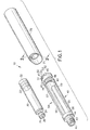
- Fig. 1 is a perspective view of the medication delivery pen 10 having a pen injector body 70 and a vial retainer 40 that receives a standard vial 30 or alternatively a threaded vial (described below).
- Vial 30 includes a distal end 31 and an open proximal end 32 with a septum 35 held on to distal end 31 by a cap 34.
- Vial 30 also includes an axially slidable piston 33 that seals open proximal end 32 and is moveable to dispense medication from vial 30 during an injection procedure performed by medication delivery pen 10.
- Vial retainer 40 includes a distal end 41 and a proximal end 42, wherein distal end 41 further includes a set of needle attachment threads 43 and extends from a vial retainer shoulder 44. Needle attachment threads 43 are intended for receiving a standard pen needle having matching threads within its hub. Vial retainer 40 also includes means for attaching vial retainer 40 to pen injector body 70. These attachment means include a plurality of cam tracks 45 on an outer surface 46 of vial retainer 40. Each cam track 45 is defined by an axial section 47 and a radial section 48 extending around the circumference of vial retainer 40.
- Radial section 48 has a slope that varies from axial section 47 to an end wall 49 which provides for sufficient force to attach vial retainer 40 to pen injector 70, as described below.
- Cam track 45 also includes an axial protrusion 50 in axial section 47 and a radial protrusion 51 in radial section 48, which together define a loading pocket 52 there between.
- Proximal end 42 of vial retainer 40 also includes a plurality of ratchet fingers 53 extending inwardly.
- Vial retainer 40 also includes a center portion 54 located between distal end 41 and proximal end 42 having a viewing window 55 on one side and a larger side opening 56 on the other side.
- Larger side opening 56 is defined by a pair of flexible snap wings 57 that are both ear-shaped having a narrow portion 58 near the distal end of opening 56 and a wider portion 59 near the proximal end of opening 56.
- Opening 56 also includes a stress relief 60 at the proximal end of wing 57 near wide portion 59.
- Flexible snap wings 57 are designed to spread apart to accept and retain vial 30 within opening 56 and within vial retainer 40, as further described below.
- Fig. 2 is a cross-section view of pen injector body 70 which includes an outer sleeve 72 and an inner sleeve 73 at its distal end 71.
- Inner sleeve 73 is connected to outer sleeve 72 by an inner wall 74 and outer sleeve 72 includes an plurality of cam followers 75 on its inside surface 76.
- Inner sleeve 73 is spaced from inside surface 76 of outer sleeve 72 and includes a distal edge 77 and a radial ratchet 78 on an outside surface 79 located adjacent to inner wall 74 and begins at a distance from distal edge 77 near cam followers 75 on inside surface 76.
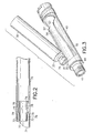
- Figs. 3 and 4 are perspective views of vial retainer 40 showing the process of loading vial 30 through side opening 56 and into vial retainer 40.
- Fig. 4 shows the action of spreading the pair of flexible snap wings 57 to accept and retain vial 30 within side opening 56.
- distal end 31 of vial 30 is inserted into narrow portion 58 of opening 56 so that cap 34 and septum 35 are received in distal end 41 of vial retainer 40.
- a shoulder 37 on vial 30 is moved into contact with vial retainer shoulder 44 on vial retainer 40 as clearly shown in Fig. 5 where medication delivery pen 10 has been assembled into a shipping position and vial 30 has been fully loaded and retained within side opening 56 of vial retainer 40.
- Fig. 6 is a cross-sectional view along the line 6-6 shown in Fig. 5 that more clearly shows the position of each cam follower 75 in each cam track 45 and, more particularly that each cam follower 75 is positioned in a loading pocket 52 defined by radial protrusion 51 shown in Fig. 6 and axial protrusion 50 shown in Fig. 7.
- Fig. 7 is a partial longitudinal cross-sectional view along lines 7-7.
- Fig. 6 also shows relative positions of outer sleeve 72, inner sleeve 73 having radial ratchet 78 and proximal end 42 of vial retainer 40 there between.
- vial retainer 40 is then rotated in the direction of Arrow while hold pen injector body 70 such that each cam follower 75 leaves shipping pocket 52 so to travel through radial section 48 of each cam track 45 until vial retainer 40 reaches a ready to use position, as shown in Fig. 8.
- each cam follower 75 has moved through a portion of radial section 48 having a predefined variable slope to provide sufficient axial force between distal edge 77 of inner sleeve 73 within pen injector body 70 and proximal end 32 of vial 30 to fully seat vial shoulder 37 on vial retainer shoulder 44 within vial retainer 40.
- Interaction between distal edge 77 on inner sleeve 73 is with proximal end 32 of vial 30 is more clearly shown in Fig. 10, described below.
- Fig. 9 is a cross-sectional view of medication delivery pen 10 shown in Fig. 8 along line 9-9 and more clearly shows interaction between ratchet fingers 53 on proximal end 42 of vial retainer 40 and radial ratchet 78 on inner sleeve 73, which together prevent backwards rotation or movement of cam followers 75 backward within cam track 45. Therefore, ratchet fingers 53 and radial ratchet 78 ensure that the force being applied by distal edge 77 on proximal end 32 of vial 30 is constant and sufficient to retain vial 30 in position.
- Fig. 10 is a cross-sectional view of an alternative medication delivery pen 10 having a release mechanism to release the forces being applied by distal edge 77 of inner sleeve 73 against proximal end 32 of vial 30.
- the release mechanism includes a release plunger 90, spring 91 and an expandable collet 92.
- the release plunger 90 includes a thumb flange 93 extending from its main body which includes a distal end extension 95 and a shoulder 96.
- Spring 91 is held between shoulder 96 and inner wall 74 of pen injector body 70 and extension 95 of release plunger 90 is received within a proximal end 98 of expandable collet 92.
- Expandable collet 92 also includes a plurality of release fingers 99 extending from a distal end 97.
- Fig. 11 is a cross-sectional view along line 11-11 showing ratchet fingers engaged in radial ratchet 78 as they would be, for example, when medication delivery pen 10 is in the ready to use position as described above.
- Fig. 11 shows the position of release fingers 99 and there corresponding ratchet fingers 53.
- a medication delivery pen 10 incorporating this release mechanism will provide for release of the medication delivery pen 10 from its ready to use position so that vial 30 could be removed from vial retainer 45 to use moving release plunger 90 in the distal direction against the force of spring 91 go to move extension 95 into expandable collet 92 and thereby expand collet 92 to force release fingers 99 to disengage ratchet fingers 53 from radial ratchet 78.
- This process would then allow rotation of vial retainer 40 in the opposite direction back to its shipping position at which vial 30 could be removed from side opening 56.
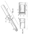
- Fig. 12 is a perspective view of an alternative vial retainer 100 having a distal end 101 and a proximal end 102, wherein distal end 101 does not include threads as in the earlier embodiment.
- Threadless vial retainer 100 includes a front retainer clip 103 having a ring 104 and a plurality of fingers 105 extending therefrom.
- retainer clip 103 can be made from stainless steal or polycarbonate and vial retainer 100 can be made of polypropylene. In any event, it is important for retainer clip 103 to be made from a material that is less flexible that the material used to make wings 57 on vial retainer 100.
- threadless vial retainer 100 would be used with a threaded vial 120 having threads internally molded or attached thereto, as shown in Fig. 12. Vial 120 would be inserted into side opening 56 and retained with threadless retainer 100, as described above in the earlier embodiment.
- Figs. 13 and 14 show another alternative medication delivery pen 200 having different means for attaching a vial retainer 240 to a pen injector body 270. All the other features and characteristics of medication delivery pen 200 would be the same as the above described medication delivery pen 10.
- the means for attached vial retainer 240 to pen injector body 270 include a set of ratchet teeth 253 at a proximal end 242 of vial retainer 240 that meet with a set of linear mating ratchet teeth within an inside surface 276 of an outer sleeve 272 near a distal end 271 of pen injector body 270. Linear mating teeth are 279.
- Vial retainer 240 would be attached to pen injector body 270 by insert proximal end 242 of vial retainer 240 into distal end 271 of pen injector body 270 until sufficient force has been applied by a distal edge 277 of an inner sleeve 273 within pen injector body 270 against proximal end 32 of vial 30 at which point linear ratchet teeth 253 would be properly engaged with linear mating ratchet teeth 279, thereby firmly attaching vial retainer 240 to pen injector body 270.
Description
Claims (6)
- A medication delivery pen (10) comprising:characterized in thata pen injector body (70) having a distal end (71);a vial retainer (40) for receiving and holding a vial (30) and having a distal end (41) and a proximal end (42),
said medication delivery pen (10) comprises means for attaching said vial retainer (40) to said pen injector body (70) in a shipping/loading position and a ready-to-use position, including
a plurality of cam followers (75) within said pen injector body (70); and
plurality of cam tracks (45) on said vial retainer (40),
wherein said cam tracks (45) have a predefined variable slope that functions to provide a predefined axial force between said vial retainer (40) and said pen injector body (70), and
wherein the vial (30) can be loaded into said vial retainer (40) when said attaching means is in the shipping/loading position, and
wherein said vial retainer (40) and said pen injector body (70) are ready to perform an injection when said attaching means is in the ready-to-use position; and that
said medication delivery pen (10) comprises means for preventing said cam followers (75) from moving from said ready-to-use position to said shipping/loading position, including:a plurality of ratchet fingers (53) on said vial retainer (40) ; anda ratchet (78) on said pen injector body (70) that mates with said ratchet fingers (53) to prevent said cam followers (75) from moving backward in said respective cam track (45). - A medication delivery pen (10) according to Claim 1, wherein said vial retainer (40) further includes means for attaching a pen-needle to said distal end (41).
- A medication delivery pen (10) according to one of the claims 1-2, wherein each cam track (45) includes an axial section (47) and a radial section (48), said radial section (48) having a variable slope and a radial protrusion (51) and said axial section (47) having an axial protrusion (50)
wherein a loading pocket (52) is formed within said cam track (45) between said axial protrusion (50) and said radial protrusion (51). - A medication delivery pen (10) according to one of the claims 1-3, further comprising a release mechanism for releasing said preventing means to release said attaching means from the ready-to-use position to return to the shipping/loading position.
- A medication delivery pen (10) according to claim 4, wherein said release mechanism includes a finger (99) that interacts with said ratchet fingers (53) on said vial retainer (40) to disengage said ratchet fingers (53) from said ratchet (78) within said pen injector body (70) so that each cam follower (75) can move back down its
respective cam track (45) to allow said vial (30) to be removed from said
vial retainer (40) when said attaching means has been returned to the shipping/loading position. - A medication delivery pen (10) according to claim 5, wherein said release mechanism further includes a release plunger (90) having an extension (95) that is received by an expandable collet (92), such that when said release plunger (90) is pushed in a distal direction said collet (92) expands to thereby push said finger (99) into engagement with said ratchet fingers (53) on said vial retainer (40).
Applications Claiming Priority (2)
| Application Number | Priority Date | Filing Date | Title |
|---|---|---|---|
| US27770 | 1998-02-23 | ||
| US09/027,770 US6090082A (en) | 1998-02-23 | 1998-02-23 | Vial retainer interface to a medication delivery pen |
Publications (3)
| Publication Number | Publication Date |
|---|---|
| EP0937474A2 EP0937474A2 (en) | 1999-08-25 |
| EP0937474A3 EP0937474A3 (en) | 2000-02-02 |
| EP0937474B1 true EP0937474B1 (en) | 2005-08-17 |
Family
ID=21839704
Family Applications (1)
| Application Number | Title | Priority Date | Filing Date |
|---|---|---|---|
| EP99102377A Expired - Lifetime EP0937474B1 (en) | 1998-02-23 | 1999-02-08 | Vial retainer interface to a medication delivery pen |
Country Status (4)
| Country | Link |
|---|---|
| US (1) | US6090082A (en) |
| EP (1) | EP0937474B1 (en) |
| CA (1) | CA2262143C (en) |
| DE (1) | DE69926675T2 (en) |
Families Citing this family (53)
| Publication number | Priority date | Publication date | Assignee | Title |
|---|---|---|---|---|
| US20020173748A1 (en) * | 1998-10-29 | 2002-11-21 | Mcconnell Susan | Reservoir connector |
| EP2223713A3 (en) * | 1998-10-29 | 2015-02-18 | Medtronic MiniMed, Inc. | Connection interface between a reservoir and an infusion pump |
| IL148899A0 (en) * | 1999-09-29 | 2002-09-12 | Sterling Medivations Inc | Reusable medication delivery device |
| US20020193740A1 (en) | 1999-10-14 | 2002-12-19 | Alchas Paul G. | Method of intradermally injecting substances |
| US6569143B2 (en) | 1999-10-14 | 2003-05-27 | Becton, Dickinson And Company | Method of intradermally injecting substances |
| US6382204B1 (en) * | 1999-10-14 | 2002-05-07 | Becton Dickinson And Company | Drug delivery system including holder and drug container |
| US6569123B2 (en) | 1999-10-14 | 2003-05-27 | Becton, Dickinson And Company | Prefillable intradermal injector |
| US6843781B2 (en) * | 1999-10-14 | 2005-01-18 | Becton, Dickinson And Company | Intradermal needle |
| US6776776B2 (en) * | 1999-10-14 | 2004-08-17 | Becton, Dickinson And Company | Prefillable intradermal delivery device |
| US6494865B1 (en) | 1999-10-14 | 2002-12-17 | Becton Dickinson And Company | Intradermal delivery device including a needle assembly |
| US20020077270A1 (en) * | 2000-01-31 | 2002-06-20 | Rosen Craig A. | Nucleic acids, proteins, and antibodies |
| US6607508B2 (en) | 2000-04-27 | 2003-08-19 | Invivotech, Inc. | Vial injector device |
| US20060018877A1 (en) * | 2001-06-29 | 2006-01-26 | Mikszta John A | Intradermal delivery of vacccines and therapeutic agents |
| WO2003002069A2 (en) * | 2001-06-29 | 2003-01-09 | Becton, Dickinson And Company | Intradermal delivery of vaccines and gene therapeutic agents via microcannula |
| US20050010174A1 (en) * | 2002-06-04 | 2005-01-13 | Berman Irwin R. | Applicator and methods of applying a substance |
| US7125394B2 (en) * | 2002-06-04 | 2006-10-24 | Syringe, Llc | Applicator for dispensing a medicinal substance |
| US7141036B2 (en) * | 2002-06-04 | 2006-11-28 | Syringe, Llc | Methods of applying a medicinal substance |
| AU2003303702A1 (en) * | 2003-01-13 | 2004-08-10 | Koninklijke Philips Electronics N.V. | Navigating to content in a recording |
| US20040253281A1 (en) * | 2003-06-12 | 2004-12-16 | Atrium Medical Corp. | Therapeutic markings applied to tissue |
| CN100398164C (en) * | 2004-04-02 | 2008-07-02 | 郑建勋 | Safety injection needle cylinder |
| US20050251152A1 (en) * | 2004-05-05 | 2005-11-10 | Atrium Medical Corp. | Illuminated medicated ink marker |
| CN101977645B (en) * | 2008-04-10 | 2013-01-30 | 松下电器产业株式会社 | Medication administering device |
| WO2009143255A1 (en) * | 2008-05-20 | 2009-11-26 | Avant Medical Corp. | Autoinjector system |
| US8052645B2 (en) | 2008-07-23 | 2011-11-08 | Avant Medical Corp. | System and method for an injection using a syringe needle |
| GB2461694A (en) * | 2008-07-08 | 2010-01-13 | Weston Terence E | Side-loaded pen injector |
| CA2695265A1 (en) * | 2010-03-02 | 2011-09-02 | Duoject Medical Systems Inc. | Injection device |
| US20130267905A1 (en) * | 2010-12-13 | 2013-10-10 | Axel Teucher | Non-detachable reservoir holder for a drug delivery device |
| US10195345B2 (en) * | 2010-12-22 | 2019-02-05 | Sanofi-Aventis Deutschland Gmbh | Dedicated cartridge |
| CA3021845C (en) | 2011-04-20 | 2022-03-29 | Amgen Inc. | Autoinjector apparatus |
| TWI538707B (en) * | 2011-05-06 | 2016-06-21 | 賽諾菲阿凡提斯德意志有限公司 | Drug delivery device and cartridge holder for a drug delivery device |
| US8528569B1 (en) | 2011-06-28 | 2013-09-10 | Kyle D. Newton | Electronic cigarette with liquid reservoir |
| EP2601992A1 (en) | 2011-12-08 | 2013-06-12 | Sanofi-Aventis Deutschland GmbH | Syringe carrier |
| EP2601988A1 (en) | 2011-12-08 | 2013-06-12 | Sanofi-Aventis Deutschland GmbH | Syringe carrier |
| US20140358093A1 (en) * | 2012-01-25 | 2014-12-04 | Novo Nordisk A/S | Drug Delivery Device with Cartridge Fixation Feature |
| JP6228935B2 (en) | 2012-02-24 | 2017-11-08 | ノボ・ノルデイスク・エー/エス | Drug delivery device having a front insertion structure |
| CA2904661C (en) | 2013-03-15 | 2022-03-15 | Amgen Inc. | Drug cassette, autoinjector, and autoinjector system |
| JP6316945B2 (en) * | 2013-05-21 | 2018-04-25 | ノボ・ノルデイスク・エー/エス | Drug delivery device having piston rod coupler |
| EP2999503A1 (en) | 2013-05-21 | 2016-03-30 | Novo Nordisk A/S | Frontloaded drug delivery device with actuated cartridge holder and piston rod coupling |
| CN105307712A (en) | 2013-05-21 | 2016-02-03 | 诺和诺德股份有限公司 | Frontloaded drug delivery device with dynamic axial stop feature |
| JP6297794B2 (en) | 2013-06-12 | 2018-03-20 | 株式会社ダイセル | Syringe |
| US10980273B2 (en) | 2013-11-12 | 2021-04-20 | VMR Products, LLC | Vaporizer, charger and methods of use |
| KR102256886B1 (en) | 2013-12-23 | 2021-05-31 | 쥴 랩스, 인크. | Vaporization device systems and methods |
| US10058129B2 (en) | 2013-12-23 | 2018-08-28 | Juul Labs, Inc. | Vaporization device systems and methods |
| US10076139B2 (en) | 2013-12-23 | 2018-09-18 | Juul Labs, Inc. | Vaporizer apparatus |
| TWI684414B (en) | 2014-02-06 | 2020-02-11 | 美商尤爾實驗室有限公司 | Vaporization device systems and methods |
| US10709173B2 (en) | 2014-02-06 | 2020-07-14 | Juul Labs, Inc. | Vaporizer apparatus |
| TW201705994A (en) | 2015-06-03 | 2017-02-16 | 賽諾菲阿凡提斯德意志有限公司 | Autoinjector and method of assembling |
| TW201700117A (en) | 2015-06-03 | 2017-01-01 | 賽諾菲阿凡提斯德意志有限公司 | Syringe carrier for an autoinjector and method of assembling |
| SG11201806793TA (en) | 2016-02-11 | 2018-09-27 | Juul Labs Inc | Fillable vaporizer cartridge and method of filling |
| MX2018009703A (en) | 2016-02-11 | 2019-07-08 | Juul Labs Inc | Securely attaching cartridges for vaporizer devices. |
| UA126061C2 (en) | 2016-02-25 | 2022-08-10 | Джуул Лебз, Інк. | Vaporization device control systems and methods |
| EP3241580A1 (en) * | 2016-05-03 | 2017-11-08 | Sanofi-Aventis Deutschland GmbH | Housing for an injection device |
| KR102325800B1 (en) * | 2019-06-27 | 2021-11-12 | 오스템임플란트 주식회사 | Dental syringe |
Family Cites Families (10)
| Publication number | Priority date | Publication date | Assignee | Title |
|---|---|---|---|---|
| US3026873A (en) * | 1959-03-06 | 1962-03-27 | Pfizer & Co C | Aspirating hypodermic syringe holder |
| US3811441A (en) * | 1972-02-10 | 1974-05-21 | Survival Technology | Cartridge syringe |
| US4592745A (en) * | 1984-02-29 | 1986-06-03 | Novo Industri A/S | Dispenser |
| DE3645245C2 (en) * | 1986-11-14 | 1994-01-27 | Haselmeier Wilhelm Fa | Injection appliance |
| GB8713810D0 (en) * | 1987-06-12 | 1987-07-15 | Hypoguard Uk Ltd | Measured dose dispensing device |
| US5226895A (en) * | 1989-06-05 | 1993-07-13 | Eli Lilly And Company | Multiple dose injection pen |
| JPH0531190A (en) * | 1991-07-26 | 1993-02-09 | Seikagaku Kogyo Co Ltd | Injector |
| CA2131042A1 (en) * | 1993-09-29 | 1995-03-30 | Mark A. Stiehl | Holder for cartridge-needle unit |
| NZ302558A (en) * | 1995-03-07 | 1999-11-29 | Lilly Co Eli | Dispensing apparatus with a medication cartridge with a manually adjustable metering mechanism |
| US5658259A (en) * | 1995-10-19 | 1997-08-19 | Meridian Medical Technologies, Inc. | Dental cartridge assembly auto-injector with protective needle cover |
-
1998
- 1998-02-23 US US09/027,770 patent/US6090082A/en not_active Expired - Lifetime
-
1999
- 1999-02-08 DE DE69926675T patent/DE69926675T2/en not_active Expired - Lifetime
- 1999-02-08 EP EP99102377A patent/EP0937474B1/en not_active Expired - Lifetime
- 1999-02-17 CA CA002262143A patent/CA2262143C/en not_active Expired - Lifetime
Also Published As
| Publication number | Publication date |
|---|---|
| CA2262143C (en) | 2003-07-15 |
| DE69926675D1 (en) | 2005-09-22 |
| DE69926675T2 (en) | 2006-06-08 |
| US6090082A (en) | 2000-07-18 |
| EP0937474A2 (en) | 1999-08-25 |
| EP0937474A3 (en) | 2000-02-02 |
| CA2262143A1 (en) | 1999-08-23 |
Similar Documents
| Publication | Publication Date | Title |
|---|---|---|
| EP0937474B1 (en) | Vial retainer interface to a medication delivery pen | |
| US6648859B2 (en) | Disposable, pre-filled drug cartridge | |
| US7169132B2 (en) | Medication delivery pen | |
| US5725508A (en) | Quick connect medication delivery pen | |
| US5931817A (en) | Pen needle assembly | |
| US5688251A (en) | Cartridge loading and priming mechanism for a pen injector | |
| US5827232A (en) | Quick connect medication delivery pen | |
| US5674204A (en) | Medication delivery pen cap actuated dose delivery clutch | |
| EP0897728B1 (en) | Medication delivery pen | |
| EP0937472B1 (en) | Repeat-dose medication delivery pen | |
| US5582598A (en) | Medication delivery pen with variable increment dose scale | |
| US5944700A (en) | Adjustable injection length pen needle | |
| US5569214A (en) | Dose setting knob adapter for medication delivery pen | |
| JP4439027B2 (en) | Drug delivery pen |
Legal Events
| Date | Code | Title | Description |
|---|---|---|---|
| PUAI | Public reference made under article 153(3) epc to a published international application that has entered the european phase |
Free format text: ORIGINAL CODE: 0009012 |
|
| AK | Designated contracting states |
Kind code of ref document: A2 Designated state(s): DE FR GB IT |
|
| AX | Request for extension of the european patent |
Free format text: AL;LT;LV;MK;RO;SI |
|
| PUAL | Search report despatched |
Free format text: ORIGINAL CODE: 0009013 |
|
| RIC1 | Information provided on ipc code assigned before grant |
Free format text: 7A 61M 5/00 A, 7A 61M 5/24 B |
|
| AK | Designated contracting states |
Kind code of ref document: A3 Designated state(s): AT BE CH CY DE DK ES FI FR GB GR IE IT LI LU MC NL PT SE |
|
| AX | Request for extension of the european patent |
Free format text: AL;LT;LV;MK;RO;SI |
|
| 17P | Request for examination filed |
Effective date: 20000427 |
|
| AKX | Designation fees paid |
Free format text: DE FR GB IT |
|
| 17Q | First examination report despatched |
Effective date: 20031119 |
|
| GRAP | Despatch of communication of intention to grant a patent |
Free format text: ORIGINAL CODE: EPIDOSNIGR1 |
|
| GRAS | Grant fee paid |
Free format text: ORIGINAL CODE: EPIDOSNIGR3 |
|
| GRAA | (expected) grant |
Free format text: ORIGINAL CODE: 0009210 |
|
| AK | Designated contracting states |
Kind code of ref document: B1 Designated state(s): DE FR GB IT |
|
| REG | Reference to a national code |
Ref country code: GB Ref legal event code: FG4D |
|
| REF | Corresponds to: |
Ref document number: 69926675 Country of ref document: DE Date of ref document: 20050922 Kind code of ref document: P |
|
| ET | Fr: translation filed | ||
| PLBE | No opposition filed within time limit |
Free format text: ORIGINAL CODE: 0009261 |
|
| STAA | Information on the status of an ep patent application or granted ep patent |
Free format text: STATUS: NO OPPOSITION FILED WITHIN TIME LIMIT |
|
| 26N | No opposition filed |
Effective date: 20060518 |
|
| REG | Reference to a national code |
Ref country code: FR Ref legal event code: PLFP Year of fee payment: 18 |
|
| REG | Reference to a national code |
Ref country code: FR Ref legal event code: PLFP Year of fee payment: 19 |
|
| REG | Reference to a national code |
Ref country code: FR Ref legal event code: PLFP Year of fee payment: 20 |
|
| PGFP | Annual fee paid to national office [announced via postgrant information from national office to epo] |
Ref country code: GB Payment date: 20180122 Year of fee payment: 20 Ref country code: DE Payment date: 20180122 Year of fee payment: 20 |
|
| PGFP | Annual fee paid to national office [announced via postgrant information from national office to epo] |
Ref country code: IT Payment date: 20180122 Year of fee payment: 20 Ref country code: FR Payment date: 20180123 Year of fee payment: 20 |
|
| REG | Reference to a national code |
Ref country code: DE Ref legal event code: R071 Ref document number: 69926675 Country of ref document: DE |
|
| REG | Reference to a national code |
Ref country code: GB Ref legal event code: PE20 Expiry date: 20190207 |
|
| PG25 | Lapsed in a contracting state [announced via postgrant information from national office to epo] |
Ref country code: GB Free format text: LAPSE BECAUSE OF EXPIRATION OF PROTECTION Effective date: 20190207 |