EP0938909A1 - Ventilator system - Google Patents
Ventilator system Download PDFInfo
- Publication number
- EP0938909A1 EP0938909A1 EP98119864A EP98119864A EP0938909A1 EP 0938909 A1 EP0938909 A1 EP 0938909A1 EP 98119864 A EP98119864 A EP 98119864A EP 98119864 A EP98119864 A EP 98119864A EP 0938909 A1 EP0938909 A1 EP 0938909A1
- Authority
- EP
- European Patent Office
- Prior art keywords
- ventilator
- ventilator unit
- unit
- docking stations
- gas
- Prior art date
- Legal status (The legal status is an assumption and is not a legal conclusion. Google has not performed a legal analysis and makes no representation as to the accuracy of the status listed.)
- Withdrawn
Links
Images
Classifications
-
- A—HUMAN NECESSITIES
- A61—MEDICAL OR VETERINARY SCIENCE; HYGIENE
- A61M—DEVICES FOR INTRODUCING MEDIA INTO, OR ONTO, THE BODY; DEVICES FOR TRANSDUCING BODY MEDIA OR FOR TAKING MEDIA FROM THE BODY; DEVICES FOR PRODUCING OR ENDING SLEEP OR STUPOR
- A61M16/00—Devices for influencing the respiratory system of patients by gas treatment, e.g. mouth-to-mouth respiration; Tracheal tubes
- A61M16/021—Devices for influencing the respiratory system of patients by gas treatment, e.g. mouth-to-mouth respiration; Tracheal tubes operated by electrical means
- A61M16/022—Control means therefor
- A61M16/024—Control means therefor including calculation means, e.g. using a processor
-
- A—HUMAN NECESSITIES
- A61—MEDICAL OR VETERINARY SCIENCE; HYGIENE
- A61M—DEVICES FOR INTRODUCING MEDIA INTO, OR ONTO, THE BODY; DEVICES FOR TRANSDUCING BODY MEDIA OR FOR TAKING MEDIA FROM THE BODY; DEVICES FOR PRODUCING OR ENDING SLEEP OR STUPOR
- A61M16/00—Devices for influencing the respiratory system of patients by gas treatment, e.g. mouth-to-mouth respiration; Tracheal tubes
- A61M16/0057—Pumps therefor
- A61M16/0066—Blowers or centrifugal pumps
-
- A—HUMAN NECESSITIES
- A61—MEDICAL OR VETERINARY SCIENCE; HYGIENE
- A61M—DEVICES FOR INTRODUCING MEDIA INTO, OR ONTO, THE BODY; DEVICES FOR TRANSDUCING BODY MEDIA OR FOR TAKING MEDIA FROM THE BODY; DEVICES FOR PRODUCING OR ENDING SLEEP OR STUPOR
- A61M2202/00—Special media to be introduced, removed or treated
- A61M2202/02—Gases
- A61M2202/0208—Oxygen
-
- A—HUMAN NECESSITIES
- A61—MEDICAL OR VETERINARY SCIENCE; HYGIENE
- A61M—DEVICES FOR INTRODUCING MEDIA INTO, OR ONTO, THE BODY; DEVICES FOR TRANSDUCING BODY MEDIA OR FOR TAKING MEDIA FROM THE BODY; DEVICES FOR PRODUCING OR ENDING SLEEP OR STUPOR
- A61M2202/00—Special media to be introduced, removed or treated
- A61M2202/02—Gases
- A61M2202/0266—Nitrogen (N)
- A61M2202/0275—Nitric oxide [NO]
-
- A—HUMAN NECESSITIES
- A61—MEDICAL OR VETERINARY SCIENCE; HYGIENE
- A61M—DEVICES FOR INTRODUCING MEDIA INTO, OR ONTO, THE BODY; DEVICES FOR TRANSDUCING BODY MEDIA OR FOR TAKING MEDIA FROM THE BODY; DEVICES FOR PRODUCING OR ENDING SLEEP OR STUPOR
- A61M2205/00—General characteristics of the apparatus
- A61M2205/35—Communication
- A61M2205/3546—Range
- A61M2205/3561—Range local, e.g. within room or hospital
-
- A—HUMAN NECESSITIES
- A61—MEDICAL OR VETERINARY SCIENCE; HYGIENE
- A61M—DEVICES FOR INTRODUCING MEDIA INTO, OR ONTO, THE BODY; DEVICES FOR TRANSDUCING BODY MEDIA OR FOR TAKING MEDIA FROM THE BODY; DEVICES FOR PRODUCING OR ENDING SLEEP OR STUPOR
- A61M2205/00—General characteristics of the apparatus
- A61M2205/35—Communication
- A61M2205/3576—Communication with non implanted data transmission devices, e.g. using external transmitter or receiver
-
- A—HUMAN NECESSITIES
- A61—MEDICAL OR VETERINARY SCIENCE; HYGIENE
- A61M—DEVICES FOR INTRODUCING MEDIA INTO, OR ONTO, THE BODY; DEVICES FOR TRANSDUCING BODY MEDIA OR FOR TAKING MEDIA FROM THE BODY; DEVICES FOR PRODUCING OR ENDING SLEEP OR STUPOR
- A61M2205/00—General characteristics of the apparatus
- A61M2205/60—General characteristics of the apparatus with identification means
-
- A—HUMAN NECESSITIES
- A61—MEDICAL OR VETERINARY SCIENCE; HYGIENE
- A61M—DEVICES FOR INTRODUCING MEDIA INTO, OR ONTO, THE BODY; DEVICES FOR TRANSDUCING BODY MEDIA OR FOR TAKING MEDIA FROM THE BODY; DEVICES FOR PRODUCING OR ENDING SLEEP OR STUPOR
- A61M2205/00—General characteristics of the apparatus
- A61M2205/82—Internal energy supply devices
- A61M2205/8206—Internal energy supply devices battery-operated
-
- A—HUMAN NECESSITIES
- A61—MEDICAL OR VETERINARY SCIENCE; HYGIENE
- A61M—DEVICES FOR INTRODUCING MEDIA INTO, OR ONTO, THE BODY; DEVICES FOR TRANSDUCING BODY MEDIA OR FOR TAKING MEDIA FROM THE BODY; DEVICES FOR PRODUCING OR ENDING SLEEP OR STUPOR
- A61M2205/00—General characteristics of the apparatus
- A61M2205/84—General characteristics of the apparatus for treating several patients simultaneously
-
- A—HUMAN NECESSITIES
- A61—MEDICAL OR VETERINARY SCIENCE; HYGIENE
- A61M—DEVICES FOR INTRODUCING MEDIA INTO, OR ONTO, THE BODY; DEVICES FOR TRANSDUCING BODY MEDIA OR FOR TAKING MEDIA FROM THE BODY; DEVICES FOR PRODUCING OR ENDING SLEEP OR STUPOR
- A61M2209/00—Ancillary equipment
- A61M2209/08—Supports for equipment
- A61M2209/084—Supporting bases, stands for equipment
- A61M2209/086—Docking stations
-
- A—HUMAN NECESSITIES
- A61—MEDICAL OR VETERINARY SCIENCE; HYGIENE
- A61M—DEVICES FOR INTRODUCING MEDIA INTO, OR ONTO, THE BODY; DEVICES FOR TRANSDUCING BODY MEDIA OR FOR TAKING MEDIA FROM THE BODY; DEVICES FOR PRODUCING OR ENDING SLEEP OR STUPOR
- A61M2230/00—Measuring parameters of the user
- A61M2230/04—Heartbeat characteristics, e.g. ECG, blood pressure modulation
-
- A—HUMAN NECESSITIES
- A61—MEDICAL OR VETERINARY SCIENCE; HYGIENE
- A61M—DEVICES FOR INTRODUCING MEDIA INTO, OR ONTO, THE BODY; DEVICES FOR TRANSDUCING BODY MEDIA OR FOR TAKING MEDIA FROM THE BODY; DEVICES FOR PRODUCING OR ENDING SLEEP OR STUPOR
- A61M2230/00—Measuring parameters of the user
- A61M2230/08—Other bio-electrical signals
- A61M2230/10—Electroencephalographic signals
-
- A—HUMAN NECESSITIES
- A61—MEDICAL OR VETERINARY SCIENCE; HYGIENE
- A61M—DEVICES FOR INTRODUCING MEDIA INTO, OR ONTO, THE BODY; DEVICES FOR TRANSDUCING BODY MEDIA OR FOR TAKING MEDIA FROM THE BODY; DEVICES FOR PRODUCING OR ENDING SLEEP OR STUPOR
- A61M2230/00—Measuring parameters of the user
- A61M2230/20—Blood composition characteristics
- A61M2230/202—Blood composition characteristics partial carbon oxide pressure, e.g. partial dioxide pressure (P-CO2)
-
- A—HUMAN NECESSITIES
- A61—MEDICAL OR VETERINARY SCIENCE; HYGIENE
- A61M—DEVICES FOR INTRODUCING MEDIA INTO, OR ONTO, THE BODY; DEVICES FOR TRANSDUCING BODY MEDIA OR FOR TAKING MEDIA FROM THE BODY; DEVICES FOR PRODUCING OR ENDING SLEEP OR STUPOR
- A61M2230/00—Measuring parameters of the user
- A61M2230/20—Blood composition characteristics
- A61M2230/205—Blood composition characteristics partial oxygen pressure (P-O2)
Definitions
- the present invention is related to a ventilator system for providing treatment to one or several subjects.
- respirator ventilator
- Other devices are more flexible and can be used in intensive care, sub acute, etc. for providing a spectra of respiration modes.
- Servo Ventilator 300 Siemens-Elema AB, Solna, Sweden.
- the devices are either stationary, such as many devices used in intensive care, or made for transport of patients undergoing respiratory treatment. Some devices are made to be used at a patient's home, but are rarely mobile in any convenient way for the patient.
- US Patent No. 5,319,363 discloses a network for portable monitoring devices.
- the network is basically limited to a certain number of bed-sites within a hospital, e.g. a ward.
- the network comprises fixed interfaces at the bed-sites for connection by any of a number of patient care devices.
- the device is brought to the bed-site and connected to the network.
- the device is then programmed for its particular use.
- Wireless communication is also possible via antennas distributed within the network area (e.g. ward). With this system a small number of devices can be used for a larger number of bed-sites.
- the ventilator device at the emergency room has to be disconnected.
- the patient is then lifted onto a trolley and connected to a transport ventilator device.
- the patient is again disconnected, moved and connected to the ICU ventilator device. This is also the case in the network for portable devices described above, when moving a patient from one ward (or network area) to another.
- An object of the invention is to achieve a ventilator system that overcomes these and other problems.
- the ventilator system comprises a ventilator unit that is adapted to be docked in on of a plurality of docking stations.
- Each docking station has a communication interface for interacting with a matching interface in the ventilator unit.
- the communication interface and matching interface could be devised so that electronic signals, treatment gases and power can be transferred between the docking station and the ventilator unit. Electronic signals and exhaled gases can be transferred between the ventilator unit and the docking station.
- the interfaces then comprise necessary plugs and valves to avoid any leakage of gas.
- All docking stations could be connected to a network, either a network solely for the docking stations, or to a hospital network.
- Mobile docking stations are equipped with wireless communicators for connection to the network.
- the location of the ventilator unit can be determined at all times.
- they should all have individual markers of some kind and transfer this information to the network via the docking stations.
- all patient and program information in the ventilator unit can be transferred to the network.
- the docking stations could also include specific programming for the ventilator unit, which programming correlates to any specific requirement in the environment of the docking station (e. g. whether the docking station is located in an ICU).
- the operating parameters of the ventilator unit can then be adapted to certain conditions or requirements pertaining for that docking station (e. g. whether CO 2 -measurements or respiratory gas volume calculations should be made).
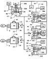
- the ventilator system shown in the figure represents one possible arrangement of interacting devices.
- the ventilator system comprises a first ventilator unit 2A and a second ventilator unit 2B.
- Each ventilator unit 2A, 2B can be connected to any of a first docking station 4A, a second docking station 4B, a third docking station 4C and a fourth docking station 4D.
- the ventilator units 2A, 2B can also be connected to a first patient 6A and second patient 6B respectively.
- the patients 6A, 6B are connected to the ventilator units 2A, 2B via tube systems 8 (since the tube system can be identical, the same reference numeral has been used).
- the docking stations 4A, 4B, 4C, 4D comprise a communication interface 10, which is adapted to receive a matching interface 12 of the ventilator units 2A, 2B.
- the communication interface 10 there are gas connections 14, 16, power line 22 and first electronic communicator 28, each adapted for corresponding gas inlets 18, 20, power inlet 26 and second electronic communicator 30 in the matching interface 12.
- the power line thus provides the docked ventilator unit 2A, 2B with power from a power source.
- the power source could be a battery 24B, power mains 24A, electric generator or any other source of power, depending on the location of the docking station 4A, 4B, 4C, 4D.
- the gas connections 14, 16 are connected to a suitable gas source.
- a suitable gas source In the figure, a fixed hospital gas supply system 42 and separate gas containers 44A, 44B for pressurised air and oxygen are shown.
- a compressor 46 e. g. a fan, a pump, or a turbine
- Other known gas sources can also be used.
- the first and second electronic communicators 28, 30 can transfer any conceivable information between the ventilator units 2A, 2B and docking stations 4A, 4B, 4C, 4D.
- information regarding the identity of the ventilator unit 2A, 2B and information regarding the treatment of the patient 6A, 6B e. g. set mode of operation, set parameters for that mode, measured parameters relating to patient, etc.
- the docking station 4A, 4B, 4C, 4D From the docking station 4A, 4B, 4C, 4D, specific programming can be transferred to the ventilator unit 2A, 2B, pertaining to special requirements or circumstances on site.
- each docking station 4A, 4B, 4C, 4D comprise a control unit 32A, 32B, 32C, 32D, containing any specific information or programming necessary for that docking station 4A, 4B, 4C, 4D.
- the ventilator units 2A, 2B can have handles 40 for easy change from one docking station to another.
- Each docking station 4A, 4B, 4C, 4D is also connected to a network, as illustrated with line 34 and network central 36 in the figure.
- the configuration of the network can be made in several ways. It could be a local network only including the docking stations 4A, 4B, 4C, 4D, but it could also be part of a larger network including other devises, such as monitors, etc.
- Any docking station 4A, 4B, 4C, 4D which is not stationary or does not have a physical connection with the network comprise means for wireless connection.
- Such combinations of networks are in themselves known, and require no further description here.
- the wireless connection could also include means for determining the position of the transmitter (GPS or any other known system for this purpose).
- Each ventilator unit 2A, 2B can have individual markers which are transferred via the interface 10, 12 to the docking station 4A, 4B, 4C, 4D to which the ventilator unit 2A, 2B is docked.
- the docking station 4A, 4B, 4C, 4D then transferring this information to the network 34, 36.
- the location of each ventilator unit 2A, 2B can be immediately obtained at all times. This inter alia allows for optimisation of use of ventilator units 2A, 2B.
- the first docking station 4A represents all docking stations for stationary use in the hospital, such as emergency rooms, ICU's, etc.
- a ventilator system of the present invention thus may include a number of first docking stations 4A equal to the number of beds for stationary treatment of patients 6A, 6B.
- the second docking station 4B represents all docking stations for mobile use, such as between bed sites in a hospital, transport to or between hospitals, etc.
- a ventilator system of the present invention thus may include a number of second docking stations 4B equal to the number of trolleys and ambulances for mobile treatment of patients 6A, 6B.
- the third and fourth docking station 4C, 4D represents docking stations for stationary or mobile subacute use in hospital or in the patient's home.
- control units 32A, 32B, 32C, 32D in the docking stations 4A, 4B, 4C, 4D can contain most of the required hardware and software for the operation of the ventilator units 2A, 2B.
- This provides for the possibility of specialising the control units 32A, 32B, 32C, 32D to their special position.
- An ICU ventilator unit needs to be more complex than a home care or subacute ventilator.
- Specialisation of different control units 32A, 32B, 32C, 32D makes it possible to reduce the size and weight of both ventilator units 2A, 2B and docking stations 4A, 4B, 4C, 4D intended for subacute or mobile use. Further specialisation is possible by transferring more of hardware and software to the network. A proper balance should be made to ensure patients safety at all times.
- the ventilator units 2A, 2B and (mobile) docking stations 4A, 4B, 4C, 4D can be made small and light, without loosing the advantages of the described system.
- the interfaces 10, 12 can be made for gas transport only, or gas transport and power supply, or electronic communication only, or any other combination.
- the interfaces 10, 12 could also include connections for transferring exhaled gas from the patient to the docking station (for further transport to evacuation or ambient, with or without purification).
- the ventilator system can be configured to be additionally controlled in relation to e. g. blood gas measurements (O 2 saturation, partial pressure of O 2 or CO 2 , etc.) ECG or EEG measurements made on the patients.
- the system could include, either separately or incorporated in ventilator units or docking stations, means for determining lung mechanical parameters such as FRC, compliance, etc.
- the docking stations could also include further connections for distributing other gases or fluids than air and oxygen, e. g. NO, laughing gas, liquid or gaseous anaesthetics (whereby the docking stations and ventilator units could be used in operating theatres as well).
- gases or fluids e. g. NO, laughing gas, liquid or gaseous anaesthetics
- ventilator units could be used in operating theatres as well.
- Different ventilator units could used, having certain specific qualities for certain defined uses, e. g. anaesthesia with one ventilator unit from sedation to awakening.
- the invention is based on the use of a plurality of docking stations with a communication interface with at least one ventilator unit having a matching interface.
Abstract
Description
- The present invention is related to a ventilator system for providing treatment to one or several subjects.
- For respiratory treatment there exist today a multitude of different ventilator (respirator) devices, many of which being highly specialised for a particular treatment such as CPAP-devices or oxygenation-devices. Other devices are more flexible and can be used in intensive care, sub acute, etc. for providing a spectra of respiration modes. One example of latter is the Servo Ventilator 300, Siemens-Elema AB, Solna, Sweden.
- The devices are either stationary, such as many devices used in intensive care, or made for transport of patients undergoing respiratory treatment. Some devices are made to be used at a patient's home, but are rarely mobile in any convenient way for the patient.
- US Patent No. 5,319,363 discloses a network for portable monitoring devices. The network is basically limited to a certain number of bed-sites within a hospital, e.g. a ward. The network comprises fixed interfaces at the bed-sites for connection by any of a number of patient care devices. The device is brought to the bed-site and connected to the network. The device is then programmed for its particular use. Wireless communication is also possible via antennas distributed within the network area (e.g. ward). With this system a small number of devices can be used for a larger number of bed-sites.
- When moving a patient, e. g. from an emergency room to intensive care, the ventilator device at the emergency room has to be disconnected. The patient is then lifted onto a trolley and connected to a transport ventilator device. In the intensive care room the patient is again disconnected, moved and connected to the ICU ventilator device. This is also the case in the network for portable devices described above, when moving a patient from one ward (or network area) to another.
- All this causes discomfort to both the patient and the personnel. Every time a new device is connected to the patient, it has to be checked for functionality and set for the proper treatment. In large hospitals, devices get spread over large areas, with no control of where they are.
- An object of the invention is to achieve a ventilator system that overcomes these and other problems.
- The object is achieved in accordance with the present invention by a ventilator system according to claim 1.
- The ventilator system comprises a ventilator unit that is adapted to be docked in on of a plurality of docking stations. Each docking station has a communication interface for interacting with a matching interface in the ventilator unit. By distributing the docking stations at any possible location where respiratory treatment can be needed, one single ventilator unit can follow a patient through any chain of treatment locations. The ventilator unit is simply picked up from one docking station and docked into another. When transporting, each trolley can be equipped with a docking station. Other docking stations can be placed in ambulances and helicopters.
- There will thus be no need to disconnect the patient at all from the ventilator unit. In consequence, there is no need for setting and programming several devices during each transport of patient. With several ventilator units, comprising matching interfaces, a complete system of ventilator units and docking stations can be obtained, where a patient basically could be moved anywhere, even between hospitals, without being disconnected from the ventilator unit.
- Advantageous improvements and embodiments of the invention are disclosed in the dependent claims to claim 1.
- The communication interface and matching interface could be devised so that electronic signals, treatment gases and power can be transferred between the docking station and the ventilator unit. Electronic signals and exhaled gases can be transferred between the ventilator unit and the docking station. The interfaces then comprise necessary plugs and valves to avoid any leakage of gas.
- All docking stations could be connected to a network, either a network solely for the docking stations, or to a hospital network. Mobile docking stations are equipped with wireless communicators for connection to the network. Hereby, the location of the ventilator unit can be determined at all times. When several ventilator units are being used, they should all have individual markers of some kind and transfer this information to the network via the docking stations. Also, all patient and program information in the ventilator unit can be transferred to the network.
- The docking stations could also include specific programming for the ventilator unit, which programming correlates to any specific requirement in the environment of the docking station (e. g. whether the docking station is located in an ICU). The operating parameters of the ventilator unit can then be adapted to certain conditions or requirements pertaining for that docking station (e. g. whether CO2-measurements or respiratory gas volume calculations should be made).
- An embodiment of the ventilator system according to the invention is described below in more detail, with reference to the figure.
- The ventilator system shown in the figure represents one possible arrangement of interacting devices. The ventilator system comprises a
first ventilator unit 2A and asecond ventilator unit 2B. Eachventilator unit first docking station 4A, asecond docking station 4B, athird docking station 4C and afourth docking station 4D. Theventilator units first patient 6A andsecond patient 6B respectively. Thepatients ventilator units - In the following description, it should be noted that where the same elements can be used, they have identical reference numbers. This, however, does not mean that they must be identical. The
docking stations communication interface 10, which is adapted to receive amatching interface 12 of theventilator units communication interface 10, there aregas connections power line 22 and firstelectronic communicator 28, each adapted forcorresponding gas inlets power inlet 26 and secondelectronic communicator 30 in thematching interface 12. - The power line thus provides the docked
ventilator unit battery 24B,power mains 24A, electric generator or any other source of power, depending on the location of thedocking station - The
gas connections gas supply system 42 andseparate gas containers - The first and second
electronic communicators ventilator units docking stations ventilator unit patient docking station docking station ventilator unit - For this purpose, each
docking station control unit docking station - The
ventilator units - Each
docking station line 34 and network central 36 in the figure. The configuration of the network can be made in several ways. It could be a local network only including thedocking stations - Any
docking station mobile docking stations - Each
ventilator unit interface docking station ventilator unit docking station network ventilator unit ventilator units - In the figure, the
first docking station 4A represents all docking stations for stationary use in the hospital, such as emergency rooms, ICU's, etc. A ventilator system of the present invention thus may include a number offirst docking stations 4A equal to the number of beds for stationary treatment ofpatients - The
second docking station 4B represents all docking stations for mobile use, such as between bed sites in a hospital, transport to or between hospitals, etc. A ventilator system of the present invention thus may include a number ofsecond docking stations 4B equal to the number of trolleys and ambulances for mobile treatment ofpatients - The third and
fourth docking station - Even if a
patient same ventilator unit different docking stations - By configuring the
control units docking stations ventilator units control units different control units ventilator units docking stations - In this manner, the
ventilator units docking stations - Even though the figure describes the ventilator system according to the invention with a multitude of possibilities, simpler systems are possible. For instance, the
interfaces - Further alternatives are also possible. The
interfaces - The ventilator system can be configured to be additionally controlled in relation to e. g. blood gas measurements (O2 saturation, partial pressure of O2 or CO2, etc.) ECG or EEG measurements made on the patients. The system could include, either separately or incorporated in ventilator units or docking stations, means for determining lung mechanical parameters such as FRC, compliance, etc.
- The docking stations could also include further connections for distributing other gases or fluids than air and oxygen, e. g. NO, laughing gas, liquid or gaseous anaesthetics (whereby the docking stations and ventilator units could be used in operating theatres as well). Different ventilator units could used, having certain specific qualities for certain defined uses, e. g. anaesthesia with one ventilator unit from sedation to awakening.
- Other alternatives and additions are also possible within the present invention. The invention is based on the use of a plurality of docking stations with a communication interface with at least one ventilator unit having a matching interface.
Claims (9)
- Ventilator system comprising at least one ventilator unit (2A, 2B) and a plurality of docking stations (4A, 4B, 4C, 4D), each docking station (4A, 4B, 4C, 4D) being adapted to receive the ventilator unit (2A, 2B) and comprising a communication interface (10) adapted to be connected to a matching interface (12) on the ventilator unit (2A, 2B) when the ventilator unit (2A, 2B) is docked in the docking station (4A, 4B, 4C, 4D), characterised in that the docking stations (4A, 4B, 4C, 4D) are arranged at different treatment sites, whereby the ventilator unit (2A, 2B) can be moved between different docking stations (4A, 4B, 4C, 4D) when necessary without interrupting the treatment of a patient (6A, 6B) connected to the ventilator unit (2A, 2B).
- Ventilator system according to claim 1, characterised in that the communication interface (10) and matching interface (12) are adapted to exchange electronic signals.
- Ventilator system according to claim 2, characterised in that the docking stations (4A, 4B, 4C, 4D) are connected to a common network (34, 36) and the electronic signals carry information identifying the ventilator unit (2A, 2B), whereby the location of the ventilator unit (2A, 2B) can be identified.
- Ventilator system according to claim 3, characterised by a plurality of ventilator units (2A, 2B), each having individual electronic identifiers, can be docked in the docking stations (4A, 4B, 4C, 4D), whereby the location of each ventilator unit (2A, 2B) can be identified.
- Ventilator system according to any of the claims 2 - 4, characterised in that the electronic signals carry information from the docking station (4A, 4B, 4C, 4D) relating to at least one operating parameter for the ventilator unit (2A, 2B).
- Ventilator system according to any of the above claims, characterised in that the communication interface (10) is adapted to supply gas from at least one gas source (42, 44A, 44B, 46) to the matching interface (12) of the ventilator unit (2A, 2B).
- Ventilator system according to claim 6, characterised in that the communication interface (10) is adapted to receive exhaled gas from the matching interface (12) of the ventilator unit (2A, 2B) for evacuation of the exhaled gas.
- Ventilator system according to claim 6 or 7, characterised in that the docking stations are adapted to be connected to any source of gas, in particular to a fixed hospital gas supply system (42), gas cylinders (44A, 44B), compressors (46) and fans.
- Ventilator system according to any of the above claims, characterised in that communication interface (10) is adapted to supply power to the matching interface (12) of the ventilator unit (2A, 2B).
Applications Claiming Priority (2)
| Application Number | Priority Date | Filing Date | Title |
|---|---|---|---|
| SE9704663A SE9704663D0 (en) | 1997-12-15 | 1997-12-15 | Fan system |
| SE9704663 | 1997-12-15 |
Publications (1)
| Publication Number | Publication Date |
|---|---|
| EP0938909A1 true EP0938909A1 (en) | 1999-09-01 |
Family
ID=20409386
Family Applications (1)
| Application Number | Title | Priority Date | Filing Date |
|---|---|---|---|
| EP98119864A Withdrawn EP0938909A1 (en) | 1997-12-15 | 1998-10-20 | Ventilator system |
Country Status (4)
| Country | Link |
|---|---|
| US (1) | US6158430A (en) |
| EP (1) | EP0938909A1 (en) |
| JP (1) | JPH11239616A (en) |
| SE (1) | SE9704663D0 (en) |
Cited By (13)
| Publication number | Priority date | Publication date | Assignee | Title |
|---|---|---|---|---|
| EP1653905A2 (en) * | 2003-08-04 | 2006-05-10 | Pulmonetic Systems, Inc. | Portable ventilator system |
| US7997885B2 (en) | 2007-12-03 | 2011-08-16 | Carefusion 303, Inc. | Roots-type blower reduced acoustic signature method and apparatus |
| US8118024B2 (en) | 2003-08-04 | 2012-02-21 | Carefusion 203, Inc. | Mechanical ventilation system utilizing bias valve |
| US8156937B2 (en) | 2003-08-04 | 2012-04-17 | Carefusion 203, Inc. | Portable ventilator system |
| US8677995B2 (en) | 2003-08-04 | 2014-03-25 | Carefusion 203, Inc. | Compressor control system for a portable ventilator |
| US8888711B2 (en) | 2008-04-08 | 2014-11-18 | Carefusion 203, Inc. | Flow sensor |
| DE102018008495A1 (en) | 2018-10-30 | 2020-04-30 | Drägerwerk AG & Co. KGaA | Valve module for a ventilation system, ventilation hose device, ventilation device, ventilation system and method for separating and establishing a fluid-communicating connection |
| DE102018008493A1 (en) | 2018-10-30 | 2020-04-30 | Drägerwerk AG & Co. KGaA | Transfer unit, ventilation device, ventilation system and method for changing a ventilation device used for a patient's ventilation process |
| WO2021191642A3 (en) * | 2020-03-26 | 2021-11-04 | Medicor Elektronika Zrt. | Ventilator system and three-way valve for a ventilator system |
| US20220084671A1 (en) * | 2020-09-15 | 2022-03-17 | Loewenstein Medical Technology S.A. | Method and system for data transfer in ventilators |
| EP4039303A1 (en) * | 2021-02-04 | 2022-08-10 | GE Precision Healthcare LLC | Ventilator systems and methods |
| EP4039304A1 (en) * | 2021-02-04 | 2022-08-10 | GE Precision Healthcare LLC | Ventilator systems and methods |
| EP4039305A1 (en) * | 2021-02-04 | 2022-08-10 | GE Precision Healthcare LLC | Ventilator systems and methods |
Families Citing this family (66)
| Publication number | Priority date | Publication date | Assignee | Title |
|---|---|---|---|---|
| CA2334408C (en) * | 1998-06-03 | 2007-03-27 | Scott Laboratories, Inc. | Apparatus and method for providing a conscious patient relief from pain and anxiety associated with medical or surgical procedures |
| ATE483490T1 (en) * | 1999-06-30 | 2010-10-15 | Univ Florida | MONITORING SYSTEM FOR FAN |
| DE19961253C1 (en) * | 1999-12-18 | 2001-01-18 | Draeger Medizintech Gmbh | Respiration apparatus has respiration pressure and respiration gas flow measured values used as setting parameters for new respiration pattern upon switching respiration pattern |
| US6651658B1 (en) * | 2000-08-03 | 2003-11-25 | Sequal Technologies, Inc. | Portable oxygen concentration system and method of using the same |
| US7100603B1 (en) | 2000-08-31 | 2006-09-05 | Alan Krasberg | System for providing protection from reactive oxygen species |
| US6839753B2 (en) * | 2001-02-23 | 2005-01-04 | Cardiopulmonary Corporation | Network monitoring systems for medical devices |
| US7891353B2 (en) * | 2002-08-29 | 2011-02-22 | Resmed Paris | Breathing assistance device with several secure respirator modes and associated method |
| CA2504852A1 (en) * | 2002-10-03 | 2004-04-15 | Scott Laboratories, Inc. | Systems and methods for providing sensor fusion |
| CA2507488A1 (en) * | 2002-10-03 | 2004-04-15 | Scott Laboratories, Inc. | Systems and methods for providing trend analysis in a sedation and analgesia system |
| US7022087B2 (en) * | 2003-03-26 | 2006-04-04 | Life Measurement, Inc. | Air circulation apparatus and methods for plethysmographic measurement chambers |
| US7527053B2 (en) | 2003-08-04 | 2009-05-05 | Cardinal Health 203, Inc. | Method and apparatus for attenuating compressor noise |
| DE102005007284B3 (en) * | 2005-02-17 | 2006-02-16 | Dräger Medical AG & Co. KGaA | Respiration system with maximum possible flexibility of servicing, with remote control coupled to breathing system via separate data lines for display and service data respectively, |
| WO2006092001A1 (en) * | 2005-03-01 | 2006-09-08 | Resmed Limited | Recognition system for an apparatus that delivers breathable gas to a patient |
| US7987848B2 (en) * | 2005-11-09 | 2011-08-02 | General Electric Company | System and method of integrating anesthesia agent monitoring in a respiratory carestation |
| EP3300757B1 (en) * | 2005-12-21 | 2019-07-17 | ResMed Pty Ltd | Identification system and method for mask and ventilator components |
| WO2007149446A2 (en) * | 2006-06-16 | 2007-12-27 | Aeiomed, Inc. | Modular positive airway pressure therapy apparatus and methods |
| DE102007019487B3 (en) * | 2007-04-25 | 2008-04-10 | Dräger Medical AG & Co. KG | Modular breathing system for patient, has stationary parts detachably attaching breathing module, and detachable connection interface for data, electrical energy and inhaled gas attached to stationary parts receiving module |
| DE202007018568U1 (en) * | 2007-05-31 | 2008-11-13 | Dräger Medical AG & Co. KG | Patient care unit with a lying surface |
| US7857222B2 (en) | 2007-08-16 | 2010-12-28 | Hand Held Products, Inc. | Data collection system having EIR terminal interface node |
| CA2733809C (en) * | 2007-08-22 | 2017-09-19 | The Research Foundation Of State University Of New York | Breathing-gas delivery and sharing system and method |
| US8640700B2 (en) | 2008-03-27 | 2014-02-04 | Covidien Lp | Method for selecting target settings in a medical device |
| WO2011038407A2 (en) * | 2009-09-28 | 2011-03-31 | Sequal Technologies Inc. | Controlling and communicating with respiratory care devices |
| EP2488977A1 (en) * | 2009-10-13 | 2012-08-22 | Cardiopulmonary Corporation | Method and apparatus for displaying data from medical devices |
| US9497092B2 (en) | 2009-12-08 | 2016-11-15 | Hand Held Products, Inc. | Remote device management interface |
| US8638200B2 (en) | 2010-05-07 | 2014-01-28 | Covidien Lp | Ventilator-initiated prompt regarding Auto-PEEP detection during volume ventilation of non-triggering patient |
| US8607789B2 (en) | 2010-06-30 | 2013-12-17 | Covidien Lp | Ventilator-initiated prompt regarding auto-PEEP detection during volume ventilation of non-triggering patient exhibiting obstructive component |
| US8607790B2 (en) | 2010-06-30 | 2013-12-17 | Covidien Lp | Ventilator-initiated prompt regarding auto-PEEP detection during pressure ventilation of patient exhibiting obstructive component |
| US8607791B2 (en) | 2010-06-30 | 2013-12-17 | Covidien Lp | Ventilator-initiated prompt regarding auto-PEEP detection during pressure ventilation |
| US8607788B2 (en) | 2010-06-30 | 2013-12-17 | Covidien Lp | Ventilator-initiated prompt regarding auto-PEEP detection during volume ventilation of triggering patient exhibiting obstructive component |
| US8676285B2 (en) | 2010-07-28 | 2014-03-18 | Covidien Lp | Methods for validating patient identity |
| US8554298B2 (en) | 2010-09-21 | 2013-10-08 | Cividien LP | Medical ventilator with integrated oximeter data |
| US8757153B2 (en) | 2010-11-29 | 2014-06-24 | Covidien Lp | Ventilator-initiated prompt regarding detection of double triggering during ventilation |
| US8757152B2 (en) | 2010-11-29 | 2014-06-24 | Covidien Lp | Ventilator-initiated prompt regarding detection of double triggering during a volume-control breath type |
| US8595639B2 (en) | 2010-11-29 | 2013-11-26 | Covidien Lp | Ventilator-initiated prompt regarding detection of fluctuations in resistance |
| US9038633B2 (en) | 2011-03-02 | 2015-05-26 | Covidien Lp | Ventilator-initiated prompt regarding high delivered tidal volume |
| US9092559B2 (en) * | 2011-08-16 | 2015-07-28 | Ethicon Endo-Surgery, Inc. | Drug delivery system with open architectural framework |
| US8539123B2 (en) | 2011-10-06 | 2013-09-17 | Honeywell International, Inc. | Device management using a dedicated management interface |
| US8621123B2 (en) | 2011-10-06 | 2013-12-31 | Honeywell International Inc. | Device management using virtual interfaces |
| US9821129B2 (en) | 2011-11-02 | 2017-11-21 | Vyaire Medical Capital Llc | Ventilation management system |
| US9072849B2 (en) | 2012-06-29 | 2015-07-07 | Carefusion 207, Inc. | Modifying ventilator operation based on patient orientation |
| US9058741B2 (en) | 2012-06-29 | 2015-06-16 | Carefusion 207, Inc. | Remotely accessing a ventilator |
| US9687618B2 (en) | 2011-11-02 | 2017-06-27 | Carefusion 207, Inc. | Ventilation harm index |
| US9177109B2 (en) | 2011-11-02 | 2015-11-03 | Carefusion 207, Inc. | Healthcare facility ventilation management |
| US9352110B2 (en) | 2012-06-29 | 2016-05-31 | Carefusion 207, Inc. | Ventilator suction management |
| US9737676B2 (en) | 2011-11-02 | 2017-08-22 | Vyaire Medical Capital Llc | Ventilation system |
| US9327090B2 (en) * | 2012-06-29 | 2016-05-03 | Carefusion 303, Inc. | Respiratory knowledge portal |
| US9027552B2 (en) | 2012-07-31 | 2015-05-12 | Covidien Lp | Ventilator-initiated prompt or setting regarding detection of asynchrony during ventilation |
| EP2931347B1 (en) | 2012-12-11 | 2018-08-08 | Koninklijke Philips N.V. | Nasal cannula system |
| RU2653837C2 (en) | 2012-12-17 | 2018-05-14 | Конинклейке Филипс Н.В. | Multi function docking module for pressure support therapy system |
| RU2657953C2 (en) * | 2012-12-20 | 2018-06-18 | Конинклейке Филипс Н.В. | Inline adapter for respiratory therapy device |
| US9380474B2 (en) | 2013-03-08 | 2016-06-28 | Cardiopulmonary Corp. | Network monitoring for active medical device alarms |
| EP2973360B1 (en) * | 2013-03-14 | 2020-02-12 | Vyaire Medical Capital LLC | Ventilation management system |
| DE102013017348B3 (en) * | 2013-10-18 | 2014-11-13 | Tni Medical Ag | Multifunctional, mobile applicator |
| US10471229B2 (en) * | 2014-08-27 | 2019-11-12 | General Electric Company | Respiratory support system and patient transfer device therefor |
| EP3218039B1 (en) | 2014-11-13 | 2018-07-25 | TNI medical AG | Multifunctional applicator which can be used in a mobile manner |
| US10315002B2 (en) | 2015-03-24 | 2019-06-11 | Ventec Life Systems, Inc. | Ventilator with integrated oxygen production |
| US11247015B2 (en) | 2015-03-24 | 2022-02-15 | Ventec Life Systems, Inc. | Ventilator with integrated oxygen production |
| US20170181694A1 (en) * | 2015-12-29 | 2017-06-29 | Ethicon Endo Surgery, Inc. | System and method for providing transitional monitoring along sedation continuum |
| US10369320B2 (en) * | 2016-01-21 | 2019-08-06 | Breathe Technologies, Inc. | Modular ventilation system |
| US10773049B2 (en) | 2016-06-21 | 2020-09-15 | Ventec Life Systems, Inc. | Cough-assist systems with humidifier bypass |
| US20180082033A1 (en) * | 2016-09-22 | 2018-03-22 | At&T Intellectual Property I, L.P. | Method and apparatus for controlling an artificial respiratory device via a network |
| EP3781244A4 (en) | 2018-05-13 | 2022-01-19 | Ventec Life Systems, Inc. | Portable medical ventilator system using portable oxygen concentrators |
| US11031126B1 (en) | 2020-04-02 | 2021-06-08 | Mast Medical Systems, Inc. | Medical therapy systems with closed-loop controls and methods of making and using the same |
| US20210316096A1 (en) * | 2020-04-14 | 2021-10-14 | Red Balloon Security, Inc. | Programmable logic controller-based scalable ventilator |
| RU2745261C1 (en) * | 2020-05-31 | 2021-03-22 | Ковалев Александр Сергеевич | Complex for the centralized distribution of the pressure of the respiratory mixture for simultaneous and individual artificial ventilation of the lungs (avl) to a group of patients and an individual gas distribution unit providing an individual patient with individual avl with the help of the complex |
| WO2023152735A1 (en) * | 2022-02-08 | 2023-08-17 | Michael Cohen | Multi-user ventilator system |
Citations (3)
| Publication number | Priority date | Publication date | Assignee | Title |
|---|---|---|---|---|
| US5319363A (en) * | 1990-08-31 | 1994-06-07 | The General Hospital Corporation | Network for portable patient monitoring devices |
| EP0707825A2 (en) * | 1994-10-20 | 1996-04-24 | Hewlett-Packard Company | Flexible patient monitoring system |
| EP0771571A1 (en) * | 1995-10-31 | 1997-05-07 | SANYO ELECTRIC Co., Ltd. | Atomiser system having pressure supply unit and atomiser sub-units |
Family Cites Families (12)
| Publication number | Priority date | Publication date | Assignee | Title |
|---|---|---|---|---|
| US4706664A (en) * | 1986-04-11 | 1987-11-17 | Puritan-Bennett Corporation | Inspiration oxygen saver |
| US4932402A (en) * | 1986-04-11 | 1990-06-12 | Puritan-Bennett Corporation | Inspiration oxygen saver |
| US5335651A (en) * | 1990-05-16 | 1994-08-09 | Hill-Rom Company, Inc. | Ventilator and care cart each capable of nesting within and docking with a hospital bed base |
| US5685314A (en) * | 1992-12-11 | 1997-11-11 | Siemens Medical Systems, Inc. | Auxiliary docking station for a patient monitoring system |
| US5375604A (en) * | 1992-12-11 | 1994-12-27 | Siemens Medical Electronics, Inc. | Transportable modular patient monitor |
| FI95427C (en) * | 1992-12-23 | 1996-01-25 | Instrumentarium Oy | data transmission system |
| US5579378A (en) * | 1993-08-25 | 1996-11-26 | Arlinghaus, Jr.; Frank H. | Medical monitoring system |
| US5689242A (en) * | 1994-07-28 | 1997-11-18 | The General Hospital Corporation | Connecting a portable device to a network |
| US5682902A (en) * | 1995-10-16 | 1997-11-04 | Hewlett-Packard Company | ECG pace pulse detection and processing |
| US5936539A (en) * | 1996-03-19 | 1999-08-10 | Siemens Medical Systems, Inc. | Method and apparatus for automatic configuration of a network node |
| US5687717A (en) * | 1996-08-06 | 1997-11-18 | Tremont Medical, Inc. | Patient monitoring system with chassis mounted or remotely operable modules and portable computer |
| US5701883A (en) * | 1996-09-03 | 1997-12-30 | Respironics, Inc. | Oxygen mixing in a blower-based ventilator |
-
1997
- 1997-12-15 SE SE9704663A patent/SE9704663D0/en unknown
-
1998
- 1998-10-20 EP EP98119864A patent/EP0938909A1/en not_active Withdrawn
- 1998-11-09 US US09/188,247 patent/US6158430A/en not_active Expired - Fee Related
- 1998-12-15 JP JP35561898A patent/JPH11239616A/en active Pending
Patent Citations (3)
| Publication number | Priority date | Publication date | Assignee | Title |
|---|---|---|---|---|
| US5319363A (en) * | 1990-08-31 | 1994-06-07 | The General Hospital Corporation | Network for portable patient monitoring devices |
| EP0707825A2 (en) * | 1994-10-20 | 1996-04-24 | Hewlett-Packard Company | Flexible patient monitoring system |
| EP0771571A1 (en) * | 1995-10-31 | 1997-05-07 | SANYO ELECTRIC Co., Ltd. | Atomiser system having pressure supply unit and atomiser sub-units |
Cited By (23)
| Publication number | Priority date | Publication date | Assignee | Title |
|---|---|---|---|---|
| US10118011B2 (en) | 2003-08-04 | 2018-11-06 | Carefusion 203, Inc. | Mechanical ventilation system utilizing bias valve |
| EP1653905A4 (en) * | 2003-08-04 | 2007-02-28 | Pulmonetic Systems Inc | Portable ventilator system |
| US8118024B2 (en) | 2003-08-04 | 2012-02-21 | Carefusion 203, Inc. | Mechanical ventilation system utilizing bias valve |
| US8156937B2 (en) | 2003-08-04 | 2012-04-17 | Carefusion 203, Inc. | Portable ventilator system |
| US8297279B2 (en) | 2003-08-04 | 2012-10-30 | Carefusion 203, Inc. | Portable ventilator system |
| US8522780B2 (en) | 2003-08-04 | 2013-09-03 | Carefusion 203, Inc. | Portable ventilator system |
| US8627819B2 (en) | 2003-08-04 | 2014-01-14 | Carefusion 203, Inc. | Portable ventilator system |
| US8677995B2 (en) | 2003-08-04 | 2014-03-25 | Carefusion 203, Inc. | Compressor control system for a portable ventilator |
| US8683997B2 (en) | 2003-08-04 | 2014-04-01 | Carefusion 203, Inc. | Portable ventilator system |
| EP1653905A2 (en) * | 2003-08-04 | 2006-05-10 | Pulmonetic Systems, Inc. | Portable ventilator system |
| US7997885B2 (en) | 2007-12-03 | 2011-08-16 | Carefusion 303, Inc. | Roots-type blower reduced acoustic signature method and apparatus |
| US8888711B2 (en) | 2008-04-08 | 2014-11-18 | Carefusion 203, Inc. | Flow sensor |
| US9713438B2 (en) | 2008-04-08 | 2017-07-25 | Carefusion 203, Inc. | Flow sensor |
| US9375166B2 (en) | 2008-04-08 | 2016-06-28 | Carefusion 203, Inc. | Flow sensor |
| DE102018008495A1 (en) | 2018-10-30 | 2020-04-30 | Drägerwerk AG & Co. KGaA | Valve module for a ventilation system, ventilation hose device, ventilation device, ventilation system and method for separating and establishing a fluid-communicating connection |
| DE102018008493A1 (en) | 2018-10-30 | 2020-04-30 | Drägerwerk AG & Co. KGaA | Transfer unit, ventilation device, ventilation system and method for changing a ventilation device used for a patient's ventilation process |
| US20200129721A1 (en) * | 2018-10-30 | 2020-04-30 | Drägerwerk AG & Co. KGaA | Transfer unit, ventilator, ventilation system, process for changing a ventilator used for a ventilation process of a patient |
| US11452837B2 (en) | 2018-10-30 | 2022-09-27 | Drägerwerk AG & Co. KGaA | Valve module for a ventilation system, ventilation tube device, ventilator, ventilation system as well as process for severing and establishing a fluid-communicating connection |
| WO2021191642A3 (en) * | 2020-03-26 | 2021-11-04 | Medicor Elektronika Zrt. | Ventilator system and three-way valve for a ventilator system |
| US20220084671A1 (en) * | 2020-09-15 | 2022-03-17 | Loewenstein Medical Technology S.A. | Method and system for data transfer in ventilators |
| EP4039303A1 (en) * | 2021-02-04 | 2022-08-10 | GE Precision Healthcare LLC | Ventilator systems and methods |
| EP4039304A1 (en) * | 2021-02-04 | 2022-08-10 | GE Precision Healthcare LLC | Ventilator systems and methods |
| EP4039305A1 (en) * | 2021-02-04 | 2022-08-10 | GE Precision Healthcare LLC | Ventilator systems and methods |
Also Published As
| Publication number | Publication date |
|---|---|
| JPH11239616A (en) | 1999-09-07 |
| US6158430A (en) | 2000-12-12 |
| SE9704663D0 (en) | 1997-12-15 |
Similar Documents
| Publication | Publication Date | Title |
|---|---|---|
| EP0938909A1 (en) | Ventilator system | |
| US7980245B2 (en) | Informative accessories | |
| AU765677B2 (en) | Control and display configuration layout | |
| US6234176B1 (en) | Data logger for transportable life support system | |
| US7040318B2 (en) | Ventilator | |
| US6848444B2 (en) | Emergency life support system | |
| US6182667B1 (en) | Display for transportable life support system | |
| US5687734A (en) | Flexible patient monitoring system featuring a multiport transmitter | |
| CN104203138B (en) | Modular medical instrument | |
| Schaefer et al. | Safety in the operating theatre--part 1: interpersonal relationships and team performance | |
| EP0919253A2 (en) | Modular anesthesia respiratory system | |
| CN105451583A (en) | Surgical suit | |
| DE10116361A1 (en) | Radio module, respirator, monitoring device therefor; Therapy device for carrying out CPAP therapy, monitoring device therefor; Systems and procedures | |
| US20210346638A1 (en) | Shared Manifold Ventilator and Method of Use | |
| JP2003500120A (en) | Manifold and regulator device | |
| US20090124868A1 (en) | Lightweight portable trauma treatment and patient monitoring device | |
| US6095138A (en) | Portable respiration apparatus, and system employing same | |
| CN105169537B (en) | A kind of lung ventilator and its application method | |
| US20230310778A1 (en) | Improvements in or relating to patient care | |
| CN205322946U (en) | Breathing machine | |
| CN116156427A (en) | Medical device location tracking | |
| KR102618686B1 (en) | A central monitoring system and method using ventilator | |
| CN212256932U (en) | Wireless intelligent ward nursing system | |
| WO2022087835A1 (en) | Networking method for medical data, and related device | |
| Heller et al. | An argument for equipping civilian hospitals with a multiple respirator system for a chemical warfare mass casualty situation. |
Legal Events
| Date | Code | Title | Description |
|---|---|---|---|
| PUAI | Public reference made under article 153(3) epc to a published international application that has entered the european phase |
Free format text: ORIGINAL CODE: 0009012 |
|
| AK | Designated contracting states |
Kind code of ref document: A1 Designated state(s): DE FR |
|
| AX | Request for extension of the european patent |
Free format text: AL;LT;LV;MK;RO;SI |
|
| 17P | Request for examination filed |
Effective date: 20000121 |
|
| AKX | Designation fees paid |
Free format text: DE FR |
|
| 17Q | First examination report despatched |
Effective date: 20020517 |
|
| RIN1 | Information on inventor provided before grant (corrected) |
Inventor name: KLAUS THORMANN Inventor name: KLAUS CHRISTIAN Inventor name: HOEGNELID, KURT Inventor name: PSAROS, GEORGIOS Inventor name: PFEIFFER, GEORG |
|
| APBN | Date of receipt of notice of appeal recorded |
Free format text: ORIGINAL CODE: EPIDOSNNOA2E |
|
| APBR | Date of receipt of statement of grounds of appeal recorded |
Free format text: ORIGINAL CODE: EPIDOSNNOA3E |
|
| RAP1 | Party data changed (applicant data changed or rights of an application transferred) |
Owner name: MAQUET CRITICAL CARE AB |
|
| APAA | Appeal reference recorded |
Free format text: ORIGINAL CODE: EPIDOS REFN |
|
| APAF | Appeal reference modified |
Free format text: ORIGINAL CODE: EPIDOSCREFNE |
|
| APBT | Appeal procedure closed |
Free format text: ORIGINAL CODE: EPIDOSNNOA9E |
|
| STAA | Information on the status of an ep patent application or granted ep patent |
Free format text: STATUS: THE APPLICATION IS DEEMED TO BE WITHDRAWN |
|
| 18D | Application deemed to be withdrawn |
Effective date: 20050503 |