EP0938974A2 - Phase change ink printing architecture suitable for high speed imaging - Google Patents
Phase change ink printing architecture suitable for high speed imaging Download PDFInfo
- Publication number
- EP0938974A2 EP0938974A2 EP99301399A EP99301399A EP0938974A2 EP 0938974 A2 EP0938974 A2 EP 0938974A2 EP 99301399 A EP99301399 A EP 99301399A EP 99301399 A EP99301399 A EP 99301399A EP 0938974 A2 EP0938974 A2 EP 0938974A2
- Authority
- EP
- European Patent Office
- Prior art keywords
- support surface
- ink
- print head
- intermediate transfer
- image
- Prior art date
- Legal status (The legal status is an assumption and is not a legal conclusion. Google has not performed a legal analysis and makes no representation as to the accuracy of the status listed.)
- Granted
Links
Images


Classifications
-
- B—PERFORMING OPERATIONS; TRANSPORTING
- B41—PRINTING; LINING MACHINES; TYPEWRITERS; STAMPS
- B41J—TYPEWRITERS; SELECTIVE PRINTING MECHANISMS, i.e. MECHANISMS PRINTING OTHERWISE THAN FROM A FORME; CORRECTION OF TYPOGRAPHICAL ERRORS
- B41J2/00—Typewriters or selective printing mechanisms characterised by the printing or marking process for which they are designed
- B41J2/005—Typewriters or selective printing mechanisms characterised by the printing or marking process for which they are designed characterised by bringing liquid or particles selectively into contact with a printing material
- B41J2/01—Ink jet
- B41J2/135—Nozzles
- B41J2/14—Structure thereof only for on-demand ink jet heads
- B41J2/14016—Structure of bubble jet print heads
-
- B—PERFORMING OPERATIONS; TRANSPORTING
- B41—PRINTING; LINING MACHINES; TYPEWRITERS; STAMPS
- B41J—TYPEWRITERS; SELECTIVE PRINTING MECHANISMS, i.e. MECHANISMS PRINTING OTHERWISE THAN FROM A FORME; CORRECTION OF TYPOGRAPHICAL ERRORS
- B41J11/00—Devices or arrangements of selective printing mechanisms, e.g. ink-jet printers or thermal printers, for supporting or handling copy material in sheet or web form
- B41J11/0015—Devices or arrangements of selective printing mechanisms, e.g. ink-jet printers or thermal printers, for supporting or handling copy material in sheet or web form for treating before, during or after printing or for uniform coating or laminating the copy material before or after printing
- B41J11/002—Curing or drying the ink on the copy materials, e.g. by heating or irradiating
-
- B—PERFORMING OPERATIONS; TRANSPORTING
- B41—PRINTING; LINING MACHINES; TYPEWRITERS; STAMPS
- B41J—TYPEWRITERS; SELECTIVE PRINTING MECHANISMS, i.e. MECHANISMS PRINTING OTHERWISE THAN FROM A FORME; CORRECTION OF TYPOGRAPHICAL ERRORS
- B41J2/00—Typewriters or selective printing mechanisms characterised by the printing or marking process for which they are designed
- B41J2/005—Typewriters or selective printing mechanisms characterised by the printing or marking process for which they are designed characterised by bringing liquid or particles selectively into contact with a printing material
- B41J2/0057—Typewriters or selective printing mechanisms characterised by the printing or marking process for which they are designed characterised by bringing liquid or particles selectively into contact with a printing material where an intermediate transfer member receives the ink before transferring it on the printing material
-
- B—PERFORMING OPERATIONS; TRANSPORTING
- B41—PRINTING; LINING MACHINES; TYPEWRITERS; STAMPS
- B41J—TYPEWRITERS; SELECTIVE PRINTING MECHANISMS, i.e. MECHANISMS PRINTING OTHERWISE THAN FROM A FORME; CORRECTION OF TYPOGRAPHICAL ERRORS
- B41J2/00—Typewriters or selective printing mechanisms characterised by the printing or marking process for which they are designed
- B41J2/005—Typewriters or selective printing mechanisms characterised by the printing or marking process for which they are designed characterised by bringing liquid or particles selectively into contact with a printing material
- B41J2/01—Ink jet
- B41J2/135—Nozzles
- B41J2/145—Arrangement thereof
- B41J2/155—Arrangement thereof for line printing
-
- B—PERFORMING OPERATIONS; TRANSPORTING
- B41—PRINTING; LINING MACHINES; TYPEWRITERS; STAMPS
- B41J—TYPEWRITERS; SELECTIVE PRINTING MECHANISMS, i.e. MECHANISMS PRINTING OTHERWISE THAN FROM A FORME; CORRECTION OF TYPOGRAPHICAL ERRORS
- B41J25/00—Actions or mechanisms not otherwise provided for
- B41J25/001—Mechanisms for bodily moving print heads or carriages parallel to the paper surface
-
- B—PERFORMING OPERATIONS; TRANSPORTING
- B41—PRINTING; LINING MACHINES; TYPEWRITERS; STAMPS
- B41J—TYPEWRITERS; SELECTIVE PRINTING MECHANISMS, i.e. MECHANISMS PRINTING OTHERWISE THAN FROM A FORME; CORRECTION OF TYPOGRAPHICAL ERRORS
- B41J11/00—Devices or arrangements of selective printing mechanisms, e.g. ink-jet printers or thermal printers, for supporting or handling copy material in sheet or web form
- B41J11/0015—Devices or arrangements of selective printing mechanisms, e.g. ink-jet printers or thermal printers, for supporting or handling copy material in sheet or web form for treating before, during or after printing or for uniform coating or laminating the copy material before or after printing
- B41J11/002—Curing or drying the ink on the copy materials, e.g. by heating or irradiating
- B41J11/0024—Curing or drying the ink on the copy materials, e.g. by heating or irradiating using conduction means, e.g. by using a heated platen
-
- B—PERFORMING OPERATIONS; TRANSPORTING
- B41—PRINTING; LINING MACHINES; TYPEWRITERS; STAMPS
- B41J—TYPEWRITERS; SELECTIVE PRINTING MECHANISMS, i.e. MECHANISMS PRINTING OTHERWISE THAN FROM A FORME; CORRECTION OF TYPOGRAPHICAL ERRORS
- B41J2/00—Typewriters or selective printing mechanisms characterised by the printing or marking process for which they are designed
- B41J2/005—Typewriters or selective printing mechanisms characterised by the printing or marking process for which they are designed characterised by bringing liquid or particles selectively into contact with a printing material
- B41J2/01—Ink jet
- B41J2/17—Ink jet characterised by ink handling
- B41J2/175—Ink supply systems ; Circuit parts therefor
- B41J2/17593—Supplying ink in a solid state
-
- B—PERFORMING OPERATIONS; TRANSPORTING
- B41—PRINTING; LINING MACHINES; TYPEWRITERS; STAMPS
- B41J—TYPEWRITERS; SELECTIVE PRINTING MECHANISMS, i.e. MECHANISMS PRINTING OTHERWISE THAN FROM A FORME; CORRECTION OF TYPOGRAPHICAL ERRORS
- B41J2202/00—Embodiments of or processes related to ink-jet or thermal heads
- B41J2202/01—Embodiments of or processes related to ink-jet heads
- B41J2202/14—Mounting head into the printer
-
- B—PERFORMING OPERATIONS; TRANSPORTING
- B41—PRINTING; LINING MACHINES; TYPEWRITERS; STAMPS
- B41J—TYPEWRITERS; SELECTIVE PRINTING MECHANISMS, i.e. MECHANISMS PRINTING OTHERWISE THAN FROM A FORME; CORRECTION OF TYPOGRAPHICAL ERRORS
- B41J2202/00—Embodiments of or processes related to ink-jet or thermal heads
- B41J2202/01—Embodiments of or processes related to ink-jet heads
- B41J2202/19—Assembling head units
Definitions
- This invention relates generally to an apparatus and method for high speed imaging in an ink jet printing system and, more specifically, to an apparatus and method that utilize multiple stationary print heads to print full color images by performing all of the printing process steps simultaneously.
- Ink jet printing involves ejecting ink droplets from orifices in a print head onto a receiving substrate to form an image.
- the image is made up of a grid-like pattern of potential drop locations, commonly referred to as pixels.
- the resolution of the image is expressed by the number of ink drops or dots per inch (dpi), with common resolutions being 300 dpi and 600dpi.
- Ink-jet printing systems commonly utilize either direct printing or offset printing architecture.
- ink is ejected from jets in the print head directly onto the final receiving substrate.
- an intermediate transfer surface such as a liquid layer
- a support surface such as a drum.
- the print head jets the ink onto the intermediate transfer surface to form an ink image thereon.
- the final receiving substrate is then brought into contact with the intermediate transfer surface and the ink image is transferred and fused to the final receiving substrate.
- U.S. Patent 5,389,958 entitled IMAGING PROCESS and assigned to the assignee of the present application is an example of an indirect or offset printing architecture that utilizes phase change ink.
- the intermediate transfer surface is applied by a wicking pad that is housed within an applicator apparatus. Prior to imaging, the applicator is raised into contact with the rotating drum to apply or replenish the liquid intermediate transfer surface.
- the applicator is retracted and the print head ejects drops of ink to form the ink image on the liquid intermediate transfer surface.
- the ink is applied in molten form, having been melted from its solid state form.
- the ink image solidifies on the liquid intermediate transfer surface by cooling to a malleable solid intermediate state as the drum continues to rotate.
- a transfer roller is moved into contact with the drum to form a pressurized transfer nip between the roller and the curved surface of the intermediate transfer surface/drum.
- a final receiving substrate such as a sheet of media, is then fed into the transfer nip and the ink image is transferred and fixed (transfixed) to the final receiving surface by the pressure exerted on it in the nip.
- the print head and the final receiving substrate or the intermediate transfer surface move relative to one another in two dimensions as the print head jets are fired.
- the print head is translated along an X-axis in a direction perpendicular to media travel (Y-axis).
- the final receiving substrate/intermediate transfer surface is moved past the print head along the Y-axis.
- the print head "scans" over the medium/substrate and forms a dot-matrix image by selectively depositing ink drops at specific pixel locations.
- An example of this type of imaging process is disclosed in Europe Patent Application No 97 120,322.9 assigned to the assignee of the present application.
- This application discloses an imaging process that utilizes multiple revolutions of the drum to deposit the complete ink image on the intermediate transfer surface.
- the drum rotates through 28 revolutions as the print head moves in an X - axis direction perpendicular to the drum travel direction to deposit the image.
- the maximum length of a given image is limited to the circumference of the drum.
- multiple print heads may be utilized. It is also known to utilize one or more stationary print heads to eliminate the necessity of scanning across the transfer surface or media.
- An example of a multiple stationary print head printer is disclosed in U.S. Patent 5,677,719 entitled MULTIPLE PRINT HEAD INK JET PRINTER.
- Figure 8 of the '719 patent shows an alternate embodiment suitable for color printing.
- Four separate ink jets are utilized, with each of the ink jets assigned to one of the four primary colors - magenta, cyan, yellow, and black.
- the '719 patent requires multiple revolutions of the drum. One color is applied during one rotation and another color is overlayed on the next rotation. In this manner, multiple revolutions of the drum are required to form a complete, solid fill full-color ink image on the intermediate transfer surface. It follows that the maximum length of a given image is limited to the circumference of the drum.
- the '719 patent is directed to reducing the drying time of an ink droplet on the surface of the drum. More specifically, the '719 patent addresses the drying time required for an aqueous-based ink droplet to be cleanly transferred to the final receiving surface. A drying time of three seconds is disclosed, which translates to a maximum drum rotation speed of 20 revolutions per minute, corresponding to a maximum printing speed of 20 pages per minute.
- the speed of the printing architecture disclosed in the '719 patent is limited by the required drying times and the use of multiple drum revolutions for fill-color printing.
- the maximum length of an image is also limited to the circumference of the drum.
- the apparatus and method form an ink image on an intermediate transfer surface and transfer the image to a final receiving medium.
- the apparatus and method form one or more complete images on the intermediate transfer surface and transfer the image(s) to the final receiving medium in a single pass.
- the apparatus and method are capable of printing full width images having at least a portion that is a solid fill image.
- the nozzles in one or more print head modules address every pixel location across a support surface in an X-axis direction, thereby allowing the print head modules to print a complete image in a single pass.
- the apparatus and method are capable of printing a complete image by overlaying two or more component images in a single pass, with each component image having a different color.
- the apparatus and method are capable of printing images having a length greater than the circumference of the drum/support surface.
- an apparatus and related method for high speed offset ink jet printing are provided.
- Multiple print head modules form a full width ink image by ejecting ink drops onto an intermediate transfer surface on a rotating drum.
- One or more complete images are formed on the intermediate transfer surface in less than one revolution of the drum.
- the images are then transferred to a final receiving medium while additional images are simultaneously formed on the intermediate transfer surface as the drum continues to rotate.
- Two or more color component images may be overlayed to form a complete color image in less than one revolution of the drum.
- the simultaneous imaging and image transfer allow the apparatus and method to print images having a length greater than the circumference of the drum.
- Fig. 1 is a schematic illustration of a preferred embodiment of a multiple print head, offset or indirect ink jet printing apparatus 10 according to the present invention.
- An example of an offset ink jet printer architecture is disclosed in U.S. Patent No. 5,389,958 (the '958 patent) entitled IMAGING PROCESS and assigned to the assignee of the present application.
- the '958 patent is hereby specifically incorporated by reference in pertinent part.
- the imaging apparatus 10 in Fig. 1 utilizes an offset printing process to place a plurality of ink drops in imagewise fashion on a final receiving substrate.
- the apparatus 10 includes 16 print head modules 12A - 12N, 12P and 12Q positioned around a support surface or drum 14.
- the print head modules 12A - 12N, 12P and 12Q jet drops of ink 23, 25 in a molten or liquid state onto an intermediate transfer surface 9 on the drum 14.
- the intermediate transfer surface 9 is preferably a liquid layer that is applied to the drum 14 by contacting the drum with an applicator assembly 16 (See Fig. 1).
- Suitable liquids that may be used as the intermediate transfer surface include water, fluorinated oils, glycol, surfactants, mineral oil, silicone oil, functional oils and combinations thereof.
- the preferred liquid is amino silicone oil.
- the applicator assembly 16 includes a reservoir 18, a wicking pad 20 for applying the liquid and a metering blade 22 for consistently metering the liquid on the surface of the drum 14.
- Wicking pad 20 is preferably formed from any appropriate nonwoven synthetic textile with a relatively smooth surface.
- a preferred configuration can employ the smooth wicking pad 20 mounted atop a porous supporting material, such as a polyester felt. Both materials are available from BMP Corporation as BMP products NR 90 and PE 1100-UL, respectively.
- the metering blade meters the liquid to have a thickness of from about 0.025 microns to about 60 microns, and more preferably from about 0.05 to about 10 microns.
- the reservoir 18 may also be supplied by a separate liquid supply system (not shown) to insure an uninterrupted supply of liquid.
- the support surface may take the form of a drum 14 as shown in Fig. 1, or alternatively may be a belt, web, platen, or other suitable design.
- the support surface 14 may be formed from any appropriate material, such as metals including, but not limited to, aluminum, nickel or iron phosphate, elastomers, including but not limited to, fluoroelastomers, per fluoroelastomers, silicone rubber and polybutadiene, plastics, including but not limited to, polytetrafluoroethylene loaded with polyphenylene sulfide, thermoplastics such as polyethylene, nylon, and FEP thermosets such as acetals or ceramics.
- the preferred material is anodized aluminum.
- Liquid or molten ink is ejected from the print head modules 12A - 12N, 12P and 12Q onto the intermediate transfer surface 9 on the drum 14 to form an ink image thereon.
- a final receiving medium or media 11 is fed through a preheater 30 and into a transfer nip 32 formed between the drum 14 and a transfer roller 34.
- the transfer roller 34 has a metallic core, preferably steel, with an elastomeric covering having a 40 - 45 Shore D rating. Suitable elastomeric covering materials include silicones, urethanes, nitriles, EPDM and other appropriately resilient materials.
- the elastomeric covering on roller 34 engages the media 11 on the reverse side to which the ink image is transferred from the exposed surface of the intermediate transfer surface 9. As the media 11 passes through the nip 32, it is pressed against the deposited ink image to transfer the ink image to the media.
- FIG. 1 diagrammatically illustrates the sequence involved when drops of ink 23, 25, 27 and 29 forming the ink image are transferred from the liquid intermediate transfer surface 9 to the final receiving substrate 11.
- additional processing of the transferred ink image on the media 11 may be accomplished by a pair of post-processing rollers 36, 38 downstream from the transfer nip 32.
- the post-processing rollers 36, 38 create a fusing nip 39 for fusing or fixing the ink image to the media.
- the pressure within the fusing nip 39 is much greater than the pressure within the transfer nip 32.
- the transfer nip 32 need only have sufficient pressure to transfer the ink image to the media 11, while the fusing nip 39 may utilize higher pressures to fuse or fix the ink image into the media 11.
- the pressure within the transfer nip 32 is between about 10 and about 1500 pounds per square inch (psi), and more preferably between about 100 psi to about 150 psi.
- the pressure within the fusing nip 39 is between about 10 and about 2000 psi, and more preferably between about 200 and about 250 psi.
- a duplex unit 17 may also be utilized to flip the media and allow printing on both sides of the media.
- the printed media 11 may be fed from the transfer nip 32 to a second printing apparatus (not shown) where the second side of the media is printed.
- the media 11 is shown as a continuous roll, but may also be individual sheets of media.
- the liquid intermediate transfer surface 9 on the surface of drum 14 and the ink image deposited thereon are maintained within a predetermined temperature range by an appropriate heater device 28.
- Heater device 28 may be a radiant heater positioned as shown or, alternatively, positioned internally within the drum 14. Heater device 28 increases the temperature of the drum 14/ liquid intermediate transfer surface 9 from ambient temperature to between about 25° C and about 70° C or higher. This temperature is dependent upon the exact nature of the liquid employed in the intermediate transfer surface 9 and the composition of the ink. A more preferred temperature range is between about 45° C to about 52° C.
- a phase change ink is utilized in the printer 10.
- the phase change ink is initially in solid form and is then changed to a molten state by the application of heat energy to raise the temperature to about 85° C to about 150° C.
- the molten ink is then applied in raster fashion from the nozzles 42 in the print head modules 12A-12N, 12P and 12Q to the exposed surface of the liquid intermediate transfer surface 9.
- the ink cools to an intermediate temperature and solidifies to a malleable state in which it is transferred to the final receiving surface 11 via the transfer nip 32.
- This intermediate temperature where the ink is maintained in its malleable state is between about 30° C and about 80° C.
- the ink used to form the ink image preferably has fluidic and mechanical properties that meet the parameters needed for high speed indirect printing at speeds of 100 ppm and higher.
- the viscosity of the ink in a molten state must be matched to the requirements of the print head modules utilized to apply it to the intermediate transfer surface 9.
- the viscosity of the molten ink must also be optimized relative to other physical and rheological properties of the ink as a solid, such as yield strength, hardness, elastic modulus, loss modulus, ratio of the loss modulus to the elastic modulus, and ductility.
- the hardening time required for the molten ink drops on the intermediate transfer surface 9/drum 14 to reach a malleable state suitable for transfer must be sufficiently short to support the desired printing speed. For example, to allow a printing speed of 100 ppm, where the length of each page is approximately equal to the circumference of the drum 14, the hardening time of the ink drops on the intermediate transfer surface 9/drum 14 must be about 0.6 seconds or less.
- a preferred phase change ink is comprised of a phase change ink carrier composition admixed with a phase change ink compatible colorant. More specifically, the preferred phase change ink carrier composition comprises an admixture of (1) at least one urethane resin; and/or (2) at least one mixed urethane/urea resin; and (3) at least one mono-amide; and (4) at least one polyethylene wax.
- the preferred phase change ink carrier composition comprises an admixture of (1) at least one urethane resin; and/or (2) at least one mixed urethane/urea resin; and (3) at least one mono-amide; and (4) at least one polyethylene wax.
- phase change inks having various compositions may be utilized with the present invention.
- suitable alternative inks are described in U.S. Patent Nos. 4,889,560 (the '560 patent) and 5,372,852 (the '852 patent).
- the '560 patent and '852 patent are hereby specifically incorporated by reference in pertinent part.
- the inks disclosed in these patents consist of a phase change ink carrier composition comprising one or more fatty amide-containing materials, preferably consisting of a mono-amide wax and a tetra-amide resin, one or more tackifiers, one or more plasticizers and one or more antioxidants, in combination with compatible colorants.
- all of the steps involved in the printing process are performed simultaneously, or in parallel, to maximize printing speed. More specifically, the steps of applying the intermediate transfer surface 9 to the drum 14, depositing the ink image on the intermediate transfer surface, heating the intermediate transfer surface/drum 14, preheating the media 11, transferring the ink image to the media and post-processing the ink image on the media are all performed simultaneously or in parallel. Additionally, and in another important aspect of the present invention, all of these steps are performed continuously, which allows multiple complete images to be placed on the intermediate transfer surface 9 in less than one revolution of the drum 14. As these images are transferred to the media, additional multiple complete images are simultaneously jetted onto the intermediate transfer surface 9.
- the printing apparatus 10 may print at speeds above 50 pages per minute (ppm), and more preferably at 100 ppm and higher.
- ppm pages per minute
- four complete images are placed on the intermediate transfer surface 9 in less than one revolution of the drum, and the drum rotates at approximately 25 revolutions per minute (rpm) to give a printing speed of 100 ppm.
- the printing apparatus 10 may print images having a length greater than the circumference of the drum 14. As imaging and transfer occur simultaneously and continuously, an image of any length may be printed by the printing apparatus 10.
- each print head module 12A - 12N, 12P and 12Q includes a face plate containing a plurality of nozzles 42 through which the liquid ink drops are ejected.
- the face plate 4 in Figure 3 corresponds to the print head module 12I in Figure 1.
- face plate 4 includes four arrays 44A - 44D of nozzles 42.
- Array 44A is 12 nozzles across by 10 nozzles high, while arrays 44B - 44D are each 11 nozzles across by 10 nozzles high.
- This configuration yields a total of 450 nozzles 42 on the face plate 4.
- each nozzle 42 is positioned to address a different pixel location extending in the X-axis direction on the drum 14.
- the nozzles 42 are spaced apart vertically and horizontally by a distance of about 20 pixels, and each pixel has an approximate diameter or width of 1/300 inch (0.085 mm).
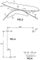
- Figure 4 is a greatly enlarged illustration of horizontally adjacent nozzles 42' and 42''' and vertically adjacent nozzles 42' and 42''. It will be appreciated that the relative placement of nozzles 42', 42'' and 42''' is representative of the relative placement of any vertically or horizontally adjacent nozzles 42 on the face plate 4.
- the horizontal centerline-to-centerline distance 20H between horizontally adjacent nozzles 42' and 42'' is 20 pixels.
- a pixel represents a single dot location within an image. The size or dimensions of a pixel will vary depending on the resolution of the image. The preferred embodiment described herein refers to printing at 300 dpi (118 dots per cm.), or 300 pixels per inch. Thus, each pixel will have an approximate diameter or width of 1/300 inch (0.085 mm.), and the above-referenced horizontal distance 20H of 20 pixels is equal to 1/15 inch.
- the vertical centerline-to-centerline distance 20V between vertically adjacent nozzles 42' and 42'' is 20 pixels, or 1/15 inch.
- the vertical rows of nozzles 42 are angled slightly.
- the horizontal centerline-to-centerline distance 2H between vertically adjacent nozzles 42 is 2 pixels, or 1/150 inch (see Fig. 4).
- vertically adjacent nozzles are offset by 2 pixels, or 1/150 inch.
- a second face plate 2 corresponding to print head module 12K is horizontally aligned to interleave with face plate 4 (see Fig. 5) to enable the printer 10 to print a complete, full width image in a single pass, or in less than one revolution of the drum 14.
- the present invention may also utilize a single, full width print head module that includes vertically adjacent nozzles that are horizontally offset by one pixel, thereby allowing this print head module to print full width, solid fill images in less than one revolution of the drum 14.
- the nozzles in face plates 4 and 2 are horizontally offset by one pixel such that the one pixel gaps between vertically adjacent nozzles in face plate 4 are filled by the nozzles in face plate 2.
- Figure 6 illustrates a portion of a horizontal line printed by face plates 4 and 2.
- Pixel 42'p is printed by nozzle 42' of face plate 4
- pixel 43'p is printed by nozzle 43' of face plate 2
- pixel 42''p is printed by nozzle 42'' of face plate 4
- pixel 43''p is printed by nozzle 43'' of face plate 2
- pixel 43''p is printed by nozzle 43'' of face plate 2 and so forth.
- nozzles 42 in face plates 4 and 2 are positioned to address every pixel location extending across the drum 14 in the X-axis direction between the leftmost nozzle 42' in face plate 4 and the rightmost nozzle 43''' in face plate 2 (see Fig. 5).
- face plates 4 and 2 are capable of printing a full width, solid fill image in a single pass, or less than one revolution of the drum 14.
- a full width image is defined as an image that spans the X-axis distance between the leftmost and the rightmost nozzles 42 in a given arrangement of print head modules/face plates.
- a solid fill image is defined as an image or a portion of an image that is fully populated with ink pixels in the X-axis direction and the Y-axis direction.
- each print head module/face plate is capable of 3 inch wide printing.
- a pair of horizontally aligned face plates such as face plates 4 and 2, supports 3 inch wide printing at 300 dpi.
- a-second pair of horizontally aligned face plates 3 and 1 corresponding to print head modules 12J and 12L, respectively, are interleaved with face plates 4, 2.
- the bottom four nozzles in the far right vertical row of face plates 3 and 1 interleave with the top four nozzles in the far left vertical row of face plates 4 and 2, respectively.
- the printer 10 utilizes four colors of ink, cyan, magenta, yellow and black, for full color printing.
- Two interleaved pairs of print head modules/face plates such as face plates 4, 3, 2 and 1, are dedicated to each of the four colors.
- the preferred embodiment of the printer 10 includes four sets of two interleaved pairs of print head modules/face plates for a total of 16 print head modules/face plates.
- the four sets of interleaved print head modules/face plates are aligned horizontally to print full color, 6 inch wide images. More specifically, each of the four interleaved pairs of print head modules/face plates prints a component image in one of the four colors.
- print head modules/face plates may be interleaved to allow for greater image widths.
- four pairs of print head modules/face plates may be interleaved for each color to support 12 inch wide printing.
- any number of colors, such as two, three or four, may be utilized for printing with the present invention.
Abstract

Description
- This invention relates generally to an apparatus and method for high speed imaging in an ink jet printing system and, more specifically, to an apparatus and method that utilize multiple stationary print heads to print full color images by performing all of the printing process steps simultaneously.
- Ink jet printing involves ejecting ink droplets from orifices in a print head onto a receiving substrate to form an image. The image is made up of a grid-like pattern of potential drop locations, commonly referred to as pixels. The resolution of the image is expressed by the number of ink drops or dots per inch (dpi), with common resolutions being 300 dpi and 600dpi.
- Ink-jet printing systems commonly utilize either direct printing or offset printing architecture. In a typical direct printing system, ink is ejected from jets in the print head directly onto the final receiving substrate. In an offset printing system, an intermediate transfer surface, such as a liquid layer, is applied to a support surface, such as a drum. The print head jets the ink onto the intermediate transfer surface to form an ink image thereon. Once the ink image has been fully deposited, the final receiving substrate is then brought into contact with the intermediate transfer surface and the ink image is transferred and fused to the final receiving substrate.
- U.S. Patent 5,389,958 entitled IMAGING PROCESS and assigned to the assignee of the present application is an example of an indirect or offset printing architecture that utilizes phase change ink. The intermediate transfer surface is applied by a wicking pad that is housed within an applicator apparatus. Prior to imaging, the applicator is raised into contact with the rotating drum to apply or replenish the liquid intermediate transfer surface.
- Once the liquid Intermediate transfer surface has been applied, the applicator is retracted and the print head ejects drops of ink to form the ink image on the liquid intermediate transfer surface. The ink is applied in molten form, having been melted from its solid state form. The ink image solidifies on the liquid intermediate transfer surface by cooling to a malleable solid intermediate state as the drum continues to rotate. When the imaging has been completed, a transfer roller is moved into contact with the drum to form a pressurized transfer nip between the roller and the curved surface of the intermediate transfer surface/drum. A final receiving substrate, such as a sheet of media, is then fed into the transfer nip and the ink image is transferred and fixed (transfixed) to the final receiving surface by the pressure exerted on it in the nip.
- One constraint with the architecture taught in the '958 patent is that each of the steps recited above must be performed in series, one after another. This greatly increases the time required to complete the printing process, and also limits the maximum length of an image to approximately the circumference of the drum. Additionally, the rotational speed of the drum during the transfix process must be considerably slower than the speed of the drum during the imaging process in order to fully transfer the ink image to the final receiving surface.
- With regard to the imaging process, in many direct and offset printing systems the print head and the final receiving substrate or the intermediate transfer surface move relative to one another in two dimensions as the print head jets are fired. Typically, the print head is translated along an X-axis in a direction perpendicular to media travel (Y-axis). The final receiving substrate/intermediate transfer surface is moved past the print head along the Y-axis. In this manner, the print head "scans" over the medium/substrate and forms a dot-matrix image by selectively depositing ink drops at specific pixel locations. An example of this type of imaging process is disclosed in Europe Patent Application No 97 120,322.9 assigned to the assignee of the present application. This application discloses an imaging process that utilizes multiple revolutions of the drum to deposit the complete ink image on the intermediate transfer surface. In the preferred embodiment, the drum rotates through 28 revolutions as the print head moves in an X - axis direction perpendicular to the drum travel direction to deposit the image. As with the architecture taught in the '958 patent, the maximum length of a given image is limited to the circumference of the drum.
- To increase image density and allow for greater speeds, multiple print heads may be utilized. It is also known to utilize one or more stationary print heads to eliminate the necessity of scanning across the transfer surface or media. An example of a multiple stationary print head printer is disclosed in U.S. Patent 5,677,719 entitled MULTIPLE PRINT HEAD INK JET PRINTER. Figure 8 of the '719 patent shows an alternate embodiment suitable for color printing. Four separate ink jets are utilized, with each of the ink jets assigned to one of the four primary colors - magenta, cyan, yellow, and black. To overlay two primary colors to achieve a secondary color, the '719 patent requires multiple revolutions of the drum. One color is applied during one rotation and another color is overlayed on the next rotation. In this manner, multiple revolutions of the drum are required to form a complete, solid fill full-color ink image on the intermediate transfer surface. It follows that the maximum length of a given image is limited to the circumference of the drum.
- The '719 patent is directed to reducing the drying time of an ink droplet on the surface of the drum. More specifically, the '719 patent addresses the drying time required for an aqueous-based ink droplet to be cleanly transferred to the final receiving surface. A drying time of three seconds is disclosed, which translates to a maximum drum rotation speed of 20 revolutions per minute, corresponding to a maximum printing speed of 20 pages per minute.
- As the above description illustrates, the speed of the printing architecture disclosed in the '719 patent is limited by the required drying times and the use of multiple drum revolutions for fill-color printing. The maximum length of an image is also limited to the circumference of the drum. Thus, a need remains for a high speed ink jet printing system that overcomes the drawbacks of the prior art.
- It is an aspect of the present invention to provide an apparatus and related method for high speed indirect ink jet printing.
- It is another aspect of the present invention that the apparatus and method form an ink image on an intermediate transfer surface and transfer the image to a final receiving medium.
- It is yet another aspect of the present invention that the apparatus and method form one or more complete images on the intermediate transfer surface and transfer the image(s) to the final receiving medium in a single pass.
- It is a feature of the present invention that the apparatus and method are capable of printing full width images having at least a portion that is a solid fill image.
- It is another feature of the present invention that the nozzles in one or more print head modules address every pixel location across a support surface in an X-axis direction, thereby allowing the print head modules to print a complete image in a single pass.
- It is yet another feature of the present invention that the apparatus and method are capable of printing a complete image by overlaying two or more component images in a single pass, with each component image having a different color.
- It is an advantage of the present invention that the apparatus and method perform all of the steps in the printing process simultaneously.
- It is another advantage of the present invention that the apparatus and method are capable of printing images having a length greater than the circumference of the drum/support surface.
- It is yet another advantage of the present invention that multiple complete images may be placed on the intermediate transfer surface in less than one revolution of the drum.
- It is still another advantage of the present invention that the apparatus and method allow duplex printing.
- To achieve the foregoing and other aspects, features and advantages, and in accordance with the purposes of the present invention as described herein, an apparatus and related method for high speed offset ink jet printing are provided. Multiple print head modules form a full width ink image by ejecting ink drops onto an intermediate transfer surface on a rotating drum. One or more complete images are formed on the intermediate transfer surface in less than one revolution of the drum. The images are then transferred to a final receiving medium while additional images are simultaneously formed on the intermediate transfer surface as the drum continues to rotate. Two or more color component images may be overlayed to form a complete color image in less than one revolution of the drum. Additionally, the simultaneous imaging and image transfer allow the apparatus and method to print images having a length greater than the circumference of the drum.
- The following description is intended to illustrate the invention, by way of example only, reference being made to the accompanying drawings in which:
- Fig. 1 is a diagrammatic illustration of a multiple print head offset ink jet printing apparatus that utilizes the apparatus and method of the present invention.
- Fig. 2 is an enlarged diagrammatic illustration of the transfer of the inked image from the liquid intermediate transfer surface to a final receiving substrate.
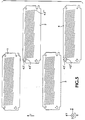
- Fig. 3 is an enlarged elevational view of a print head module face plate having four arrays of ink jet nozzles for ejecting drops of ink.
- Fig. 4 is a greatly enlarged illustration showing the spacing between two horizontally adjacent nozzles and two vertically adjacent nozzles on the face plate.
- Fig. 5 is an elevational view of four face plates that are positioned to eject drops of ink that interleave with one another to form a solid fill image.
- Fig. 6 is a schematic representation of a portion of a horizontal line printed by
face plates -
- Fig. 1 is a schematic illustration of a preferred embodiment of a multiple print head, offset or indirect ink
jet printing apparatus 10 according to the present invention. An example of an offset ink jet printer architecture is disclosed in U.S. Patent No. 5,389,958 (the '958 patent) entitled IMAGING PROCESS and assigned to the assignee of the present application. The '958 patent is hereby specifically incorporated by reference in pertinent part. - The
imaging apparatus 10 in Fig. 1 utilizes an offset printing process to place a plurality of ink drops in imagewise fashion on a final receiving substrate. In the preferred embodiment, theapparatus 10 includes 16print head modules 12A - 12N, 12P and 12Q positioned around a support surface ordrum 14. With reference now to Fig. 2, theprint head modules 12A - 12N, 12P and 12Q jet drops ofink intermediate transfer surface 9 on thedrum 14. Theintermediate transfer surface 9 is preferably a liquid layer that is applied to thedrum 14 by contacting the drum with an applicator assembly 16 (See Fig. 1). Suitable liquids that may be used as the intermediate transfer surface include water, fluorinated oils, glycol, surfactants, mineral oil, silicone oil, functional oils and combinations thereof. The preferred liquid is amino silicone oil. - As shown in Fig. 1, the
applicator assembly 16 includes areservoir 18, awicking pad 20 for applying the liquid and ametering blade 22 for consistently metering the liquid on the surface of thedrum 14. Wickingpad 20 is preferably formed from any appropriate nonwoven synthetic textile with a relatively smooth surface. A preferred configuration can employ thesmooth wicking pad 20 mounted atop a porous supporting material, such as a polyester felt. Both materials are available from BMP Corporation as BMP products NR 90 and PE 1100-UL, respectively. The metering blade meters the liquid to have a thickness of from about 0.025 microns to about 60 microns, and more preferably from about 0.05 to about 10 microns. To allow continuous imaging and printing, thewicking pad 20 andblade 22 are continuously in contact with thedrum 14. Thereservoir 18 may also be supplied by a separate liquid supply system (not shown) to insure an uninterrupted supply of liquid. - The support surface may take the form of a
drum 14 as shown in Fig. 1, or alternatively may be a belt, web, platen, or other suitable design. Thesupport surface 14 may be formed from any appropriate material, such as metals including, but not limited to, aluminum, nickel or iron phosphate, elastomers, including but not limited to, fluoroelastomers, per fluoroelastomers, silicone rubber and polybutadiene, plastics, including but not limited to, polytetrafluoroethylene loaded with polyphenylene sulfide, thermoplastics such as polyethylene, nylon, and FEP thermosets such as acetals or ceramics. The preferred material is anodized aluminum. - Liquid or molten ink is ejected from the
print head modules 12A - 12N, 12P and 12Q onto theintermediate transfer surface 9 on thedrum 14 to form an ink image thereon. A final receiving medium ormedia 11 is fed through apreheater 30 and into a transfer nip 32 formed between thedrum 14 and atransfer roller 34. In the preferred embodiment, thetransfer roller 34 has a metallic core, preferably steel, with an elastomeric covering having a 40 - 45 Shore D rating. Suitable elastomeric covering materials include silicones, urethanes, nitriles, EPDM and other appropriately resilient materials. With reference now to Fig. 2, the elastomeric covering onroller 34 engages themedia 11 on the reverse side to which the ink image is transferred from the exposed surface of theintermediate transfer surface 9. As themedia 11 passes through thenip 32, it is pressed against the deposited ink image to transfer the ink image to the media. - The pressure exerted on the ink image/
media 11 within the transfer nip 32 should be sufficient to insure that the ink image is fully transferred to themedia 11. Figure 2 diagrammatically illustrates the sequence involved when drops ofink intermediate transfer surface 9 to thefinal receiving substrate 11. Returning to Fig. 1, additional processing of the transferred ink image on themedia 11 may be accomplished by a pair ofpost-processing rollers post-processing rollers media 11, while the fusing nip 39 may utilize higher pressures to fuse or fix the ink image into themedia 11. In the preferred embodiment, the pressure within the transfer nip 32 is between about 10 and about 1500 pounds per square inch (psi), and more preferably between about 100 psi to about 150 psi. The pressure within the fusing nip 39 is between about 10 and about 2000 psi, and more preferably between about 200 and about 250 psi. - Advantageously, by utilizing a lower pressure within the transfer nip 32, less force is exerted by the
transfer roller 34 on thedrum 14 during the imaging process. This reduces the likelihood of misalignment between thedrum 14 and theprint head modules 12A-12N, 12P and 12Q, particularly in the Y-axis direction, and thereby allows for greater consistency in image quality. - With continued reference to Fig. 1, a
duplex unit 17 may also be utilized to flip the media and allow printing on both sides of the media. Alternatively, the printedmedia 11 may be fed from the transfer nip 32 to a second printing apparatus (not shown) where the second side of the media is printed. It will also be noted that themedia 11 is shown as a continuous roll, but may also be individual sheets of media. - The liquid
intermediate transfer surface 9 on the surface ofdrum 14 and the ink image deposited thereon are maintained within a predetermined temperature range by anappropriate heater device 28.Heater device 28 may be a radiant heater positioned as shown or, alternatively, positioned internally within thedrum 14.Heater device 28 increases the temperature of thedrum 14/ liquidintermediate transfer surface 9 from ambient temperature to between about 25° C and about 70° C or higher. This temperature is dependent upon the exact nature of the liquid employed in theintermediate transfer surface 9 and the composition of the ink. A more preferred temperature range is between about 45° C to about 52° C. - In the preferred embodiment, a phase change ink is utilized in the
printer 10. The phase change ink is initially in solid form and is then changed to a molten state by the application of heat energy to raise the temperature to about 85° C to about 150° C. The molten ink is then applied in raster fashion from thenozzles 42 in theprint head modules 12A-12N, 12P and 12Q to the exposed surface of the liquidintermediate transfer surface 9. The ink cools to an intermediate temperature and solidifies to a malleable state in which it is transferred to thefinal receiving surface 11 via the transfer nip 32. This intermediate temperature where the ink is maintained in its malleable state is between about 30° C and about 80° C. - The ink used to form the ink image preferably has fluidic and mechanical properties that meet the parameters needed for high speed indirect printing at speeds of 100 ppm and higher. In particular, the viscosity of the ink in a molten state must be matched to the requirements of the print head modules utilized to apply it to the
intermediate transfer surface 9. The viscosity of the molten ink must also be optimized relative to other physical and rheological properties of the ink as a solid, such as yield strength, hardness, elastic modulus, loss modulus, ratio of the loss modulus to the elastic modulus, and ductility. Additionally, the hardening time required for the molten ink drops on theintermediate transfer surface 9/drum 14 to reach a malleable state suitable for transfer must be sufficiently short to support the desired printing speed. For example, to allow a printing speed of 100 ppm, where the length of each page is approximately equal to the circumference of thedrum 14, the hardening time of the ink drops on theintermediate transfer surface 9/drum 14 must be about 0.6 seconds or less. - A preferred phase change ink is comprised of a phase change ink carrier composition admixed with a phase change ink compatible colorant. More specifically, the preferred phase change ink carrier composition comprises an admixture of (1) at least one urethane resin; and/or (2) at least one mixed urethane/urea resin; and (3) at least one mono-amide; and (4) at least one polyethylene wax. A more detailed description of the preferred phase change ink is found in European Patent Application No 99 300521.4 assigned to the assignee of the present application. This application is hereby specifically incorporated by reference in pertinent part.
- It will be appreciated that many other types of phase change inks having various compositions may be utilized with the present invention. Examples of suitable alternative inks are described in U.S. Patent Nos. 4,889,560 (the '560 patent) and 5,372,852 (the '852 patent). The '560 patent and '852 patent are hereby specifically incorporated by reference in pertinent part. The inks disclosed in these patents consist of a phase change ink carrier composition comprising one or more fatty amide-containing materials, preferably consisting of a mono-amide wax and a tetra-amide resin, one or more tackifiers, one or more plasticizers and one or more antioxidants, in combination with compatible colorants.
- In an important aspect of the present invention, all of the steps involved in the printing process are performed simultaneously, or in parallel, to maximize printing speed. More specifically, the steps of applying the
intermediate transfer surface 9 to thedrum 14, depositing the ink image on the intermediate transfer surface, heating the intermediate transfer surface/drum 14, preheating themedia 11, transferring the ink image to the media and post-processing the ink image on the media are all performed simultaneously or in parallel. Additionally, and in another important aspect of the present invention, all of these steps are performed continuously, which allows multiple complete images to be placed on theintermediate transfer surface 9 in less than one revolution of thedrum 14. As these images are transferred to the media, additional multiple complete images are simultaneously jetted onto theintermediate transfer surface 9. This also enables thedrum 14 to rotate at a fixed speed during the entire printing process, thereby avoiding the necessity of slowing the drum for the transfix process or other step. Advantageously, by performing all of the steps in parallel and continuously imaging and transferring one or more complete images, theprinting apparatus 10 may print at speeds above 50 pages per minute (ppm), and more preferably at 100 ppm and higher. In a preferred embodiment, four complete images are placed on theintermediate transfer surface 9 in less than one revolution of the drum, and the drum rotates at approximately 25 revolutions per minute (rpm) to give a printing speed of 100 ppm. - Alternatively, and in another important aspect of the present invention, the
printing apparatus 10 may print images having a length greater than the circumference of thedrum 14. As imaging and transfer occur simultaneously and continuously, an image of any length may be printed by theprinting apparatus 10. - With reference now to Figure 3, the preferred embodiment of each
print head module 12A - 12N, 12P and 12Q will now be described. Each print head module includes a face plate containing a plurality ofnozzles 42 through which the liquid ink drops are ejected. Theface plate 4 in Figure 3 corresponds to the print head module 12I in Figure 1. The following discussion offace plate 4 applies equally to the face plates on each of the other print head modules. In the preferred embodiment,face plate 4 includes fourarrays 44A - 44D ofnozzles 42.Array 44A is 12 nozzles across by 10 nozzles high, whilearrays 44B - 44D are each 11 nozzles across by 10 nozzles high. This configuration yields a total of 450nozzles 42 on theface plate 4. As explained in more detail below, eachnozzle 42 is positioned to address a different pixel location extending in the X-axis direction on thedrum 14. - In the preferred embodiment the
nozzles 42 are spaced apart vertically and horizontally by a distance of about 20 pixels, and each pixel has an approximate diameter or width of 1/300 inch (0.085 mm). The terms "horizontal" and "vertical" are used only in a general sense to indicate directions of reference, and should not be interpreted to refer to orthogonal directions. From the above description of the dimensions of thenozzle arrays 44A - 44D, it will be appreciated that theface plate 4 can support 3 inch wide printing ((45 horizontal nozzles) X (1/15 inch between nozzles) = 3 inches). - Figure 4 is a greatly enlarged illustration of horizontally
adjacent nozzles adjacent nozzles nozzles adjacent nozzles 42 on theface plate 4. As shown in Figure 4, the horizontal centerline-to-centerline distance 20H between horizontallyadjacent nozzles horizontal distance 20H of 20 pixels is equal to 1/15 inch. - With continued reference to Figure 4, the vertical centerline-to-
centerline distance 20V between verticallyadjacent nozzles nozzles 42 are angled slightly. Preferably, the horizontal centerline-to-centerline distance 2H between verticallyadjacent nozzles 42 is 2 pixels, or 1/150 inch (see Fig. 4). Alternatively expressed, vertically adjacent nozzles are offset by 2 pixels, or 1/150 inch. - With reference now to Figures 1 and 3, as the
drum 14 moves past theface plate 4 of print head module 12I, thenozzles 42 are selectively fired to place ink drops on the intermediate transfer surface on the drum. Given that vertically adjacent nozzles are horizontally offset by 2 pixels, a horizontal line printed byface plate 4 would have one pixel gaps between each printed pixel. Therefore, in an important aspect of the present invention, asecond face plate 2 corresponding to printhead module 12K is horizontally aligned to interleave with face plate 4 (see Fig. 5) to enable theprinter 10 to print a complete, full width image in a single pass, or in less than one revolution of thedrum 14. It will be appreciated that the present invention may also utilize a single, full width print head module that includes vertically adjacent nozzles that are horizontally offset by one pixel, thereby allowing this print head module to print full width, solid fill images in less than one revolution of thedrum 14. - More specifically, with reference to Figures 5 and 6, the nozzles in
face plates face plate 4 are filled by the nozzles inface plate 2. Figure 6 illustrates a portion of a horizontal line printed byface plates nozzle 42' offace plate 4, pixel 43'p is printed by nozzle 43' offace plate 2,pixel 42''p is printed bynozzle 42'' offace plate 4, pixel 43''p is printed by nozzle 43'' offace plate 2, and so forth. In this manner, thenozzles 42 inface plates drum 14 in the X-axis direction between theleftmost nozzle 42' inface plate 4 and the rightmost nozzle 43''' in face plate 2 (see Fig. 5). Thus,face plates drum 14. For the purposes of this application, a full width image is defined as an image that spans the X-axis distance between the leftmost and therightmost nozzles 42 in a given arrangement of print head modules/face plates. A solid fill image is defined as an image or a portion of an image that is fully populated with ink pixels in the X-axis direction and the Y-axis direction. - As explained above, in the preferred embodiment each print head module/face plate is capable of 3 inch wide printing. A pair of horizontally aligned face plates, such as
face plates printer 10 to print 6 inch wide solid fill images, a-second pair of horizontally alignedface plates 3 and 1, corresponding to printhead modules face plates face plates 3 and 1 interleave with the top four nozzles in the far left vertical row offace plates - With reference now to Figures 1 and 5, in the preferred embodiment the
printer 10 utilizes four colors of ink, cyan, magenta, yellow and black, for full color printing. Two interleaved pairs of print head modules/face plates, such asface plates printer 10 includes four sets of two interleaved pairs of print head modules/face plates for a total of 16 print head modules/face plates. Advantageously, the four sets of interleaved print head modules/face plates are aligned horizontally to print full color, 6 inch wide images. More specifically, each of the four interleaved pairs of print head modules/face plates prints a component image in one of the four colors. These four component images are overlayed as the drum rotates to form a complete, full color image on the intermediate transfer surface in less than one revolution of the drum. It will be appreciated that any number of print head modules/face plates may be interleaved to allow for greater image widths. For example, four pairs of print head modules/face plates may be interleaved for each color to support 12 inch wide printing. It will also be appreciated that any number of colors, such as two, three or four, may be utilized for printing with the present invention. - While the invention has been described above with references to specific embodiments thereof, it is apparent that many changes, modifications and variations in the materials, arrangements of parts and steps can be made without departing from the inventive concept disclosed herein. For example, while the preferred embodiment utilizes phase change ink, it is to be understood that the invention as described in the appended claims may be practiced with other types of inks, such as aqueous-based and solvent-based inks.
Claims (25)
- A method of offset printing in an ink jet printer (10), the method comprising the steps of:(a) creating relative motion between a support surface (14) and at least one print head module (12);(b) applying a liquid to at least a portion of the support surface (14) to form a liquid intermediate transfer surface (9) on the support surface (14);(c) forming at least a portion of a complete ink image on the liquid intermediate transfer surface (9) in a single pass between the support surface (14) and the print head module (12) by applying drops of ink (23,25) to the liquid intermediate transfer surface (9);(d) transferring at least a portion of the complete ink image to a final receiving medium (11); and(e) performing steps (a) through (d) simultaneously.
- A method as claimed in claim 1 wherein in step (c) two or more complete ink images are formed on the liquid intermediate transfer surface (9) in a single pass between the support surface (14) and the at least one print head module (12), and in step (d) at least a portion of at least one of the two or more complete ink images is transferred to the final receiving medium (11).
- A method as claimed in claim 1 or claim 2 wherein the support surface (14) is arcuate.
- A method as claimed in claim 1 or claim 2 wherein the step of creating relative motion between a support surface (14) and at least one print head module (12) further comprises the step of rotating an arcuate support surface (14) past the at least one print head module (12), and wherein the step of forming at least a portion of a complete ink image on the liquid intermediate transfer surface (9) further comprises the step of forming at least a portion of the complete ink image in less than one revolution of the arcuate support surface.
- A method as claimed in any preceding claim wherein in step (c) at least a portion of a complete ink image is formed on the liquid intermediate transfer surface (9) in less than one revolution of the support surface (14) by overlaying two or more component images, each of the component images having a different color.
- A method as claimed in any preceding claim wherein the step of forming at least a portion of a complete ink image on the liquid intermediate transfer surface (9) in a single pass further comprises the step of forming a full width image by addressing every pixel location across the support surface (14) in an X-axis direction.
- A method as claimed in any preceding claim wherein the step of forming at least a portion of a complete ink image on the liquid intermediate transfer surface (9) in a single pass further comprises the step of forming a full width image having at least a portion being a solid fill image.
- A method as claimed in any preceding claim wherein the step of rotating the support surface (14) further comprises the step of rotating the support surface (14) at 20 revolutions per minute or faster.
- A method as claimed in any preceding claim wherein the step of rotating the support surface (14) further comprises the step of rotating the support surface (14) at a fixed speed during the performance of steps (a) through (d).
- A method as claimed in any preceding claim wherein the step of forming at least a portion of a complete ink image on the liquid intermediate transfer surface (9) in a single pass further comprises the step of ejecting drops of ink (23,25) from a plurality of drop-on-demand ink jet print head modules (12).
- A method as claimed in any preceding claim wherein the ink is a phase change ink.
- A method as claimed in any preceding claim wherein the step of forming at least a portion of a complete ink image on the liquid intermediate transfer surface (9) further comprises the step of using a phase change ink that requires a hardening time on the support surface (14) of about 0.6 seconds or less.
- A method as claimed in claim 11 or claim 12 wherein the step of ejecting the drops (23,25) of phase change ink further includes the step of ejecting the drops (23,25) of ink at a temperature of about 85°C to about 150°C in a molten state onto the liquid intermediate transfer surface (9) where the ink drops (23,25) solidify into a malleable state having a temperature of between about 30°C and about 80°C.
- A method as claimed in claim 10 further comprising the step of positioning at least four of the plurality of drop-on-demand ink jet print head modules (12) at four different circumferential locations about the support surface (14).
- A method as claimed in any preceding claim wherein the step of transferring at least a portion of the complete ink image to a final receiving medium (11) further comprises the step of passing the final receiving medium (11) through a nip (32) defined by the support surface (14) and a transfer roller (34).
- A method as claimed in claim 15 further comprising the step of continuously urging the transfer roller (34) against the support surface (14) during the performance of steps (a) through (d).
- A method as claimed in any preceding claim wherein the step of applying a liquid to at least a portion of the support surface (14) further comprises the steps of:contacting the support surface (14) with an applicator (16); andmetering the liquid on the support surface to form the liquid intermediate transfer surface (9).
- A method as claimed in claim 16 wherein the step of metering the liquid on the support surface (14) further comprises the step of metering the liquid to have a thickness of from about 0.025 microns to about 60 microns.
- A method as claimed in any preceding claim wherein the step of transferring at least a portion of the complete ink image to a final receiving medium (11) further comprises the steps of:transferring the complete ink image to a first side of the final receiving medium (11); andtransferring a second ink image to a second side of the final receiving medium (11).
- A method as claimed in any preceding claim further comprising the step of preheating the final receiving medium (11) prior to transferring at least a portion of the complete ink image to the final receiving medium (11).
- A method as claimed in any preceding claim further comprising the step of maintaining the liquid intermediate transfer surface (9) and the support surface (14) within a predetermined temperature range.
- An offset ink jet printing apparatus (10) for high speed imaging, the apparatus comprising:a support surface (14) having a plurality of pixel locations extending in at least an X-axis direction;a plurality of print head modules (12) positioned adjacent to the support surface (14), each of the print head modules (12) including a face plate (4);a plurality of nozzles (42,43) located on each of the face plates (4), the plurality of nozzles (42,43) addressing every pixel location across the support surface in an X-axis direction;a first print head module (12) of the plurality of print head modules (12) horizontally aligned to interleave with at least a second print head module (12) of the plurality of print head modules (12) to print a complete image on the support surface (14) without relative motion in the X-axis direction between the support surface (14) and the first print head module (12) or the second print head module (12); anda transfer apparatus (32,34) for transferring the complete image to a final receiving medium.
- An apparatus as claimed in claim 22 wherein the support surface (14) comprises a rotatable drum (14), and the plurality of print head modules (12) are positioned in four groups around the drum, with each group of print head modules (12) ejecting a different color of ink.
- An apparatus (10) as claimed in claim 22 or claim 23 wherein the transfer apparatus comprises a roller (34) that is continuously urged against a portion of the drum (14).
- An apparatus (10) as claimed in any of claims 22 to 24 wherein the apparatus (10) also comprises means (16) for continuously applying a liquid to at least a portion of the support surface (14) to form a liquid intermediate transfer surface (9) thereon.
Applications Claiming Priority (4)
| Application Number | Priority Date | Filing Date | Title |
|---|---|---|---|
| US30672 | 1998-02-25 | ||
| US09/030,672 US6213580B1 (en) | 1998-02-25 | 1998-02-25 | Apparatus and method for automatically aligning print heads |
| US09/045,216 US6113231A (en) | 1998-02-25 | 1998-03-19 | Phase change ink printing architecture suitable for high speed imaging |
| US45216 | 1998-03-19 |
Publications (3)
| Publication Number | Publication Date |
|---|---|
| EP0938974A2 true EP0938974A2 (en) | 1999-09-01 |
| EP0938974A3 EP0938974A3 (en) | 2000-02-23 |
| EP0938974B1 EP0938974B1 (en) | 2006-08-09 |
Family
ID=26706316
Family Applications (1)
| Application Number | Title | Priority Date | Filing Date |
|---|---|---|---|
| EP99301399A Expired - Lifetime EP0938974B1 (en) | 1998-02-25 | 1999-02-25 | Phase change ink printing architecture suitable for high speed imaging |
Country Status (3)
| Country | Link |
|---|---|
| US (1) | US6113231A (en) |
| EP (1) | EP0938974B1 (en) |
| DE (1) | DE69932659T2 (en) |
Cited By (5)
| Publication number | Priority date | Publication date | Assignee | Title |
|---|---|---|---|---|
| WO2004022353A1 (en) * | 2002-09-04 | 2004-03-18 | Canon Kabushiki Kaisha | Image forming process and image forming apparatus |
| DE102006053622A1 (en) * | 2006-11-14 | 2008-05-15 | Impress Decor Gmbh | Printing method for digital printing of decorative foils has an ink-jet printer with a circulating continuous ink carrier for printing onto an absorbent printing material |
| US7419230B2 (en) | 2002-03-29 | 2008-09-02 | Olympus Corporation | Test chart geometrical characteristic analysis system geometrical characteristic analysis method printer and ink-jet printer |
| EP2011659A1 (en) * | 2007-07-05 | 2009-01-07 | Xerox Corporation | INK-Jet printer using phase-change INK printing on a continuous web |
| US8668318B2 (en) | 2012-07-26 | 2014-03-11 | Xerox Corporation | System and method for spreading ink on a media web |
Families Citing this family (33)
| Publication number | Priority date | Publication date | Assignee | Title |
|---|---|---|---|---|
| US6523949B1 (en) * | 1999-03-09 | 2003-02-25 | Brian C. Ewert | Variable image printing using inkjet printer |
| US6350889B1 (en) | 1999-06-24 | 2002-02-26 | Arizona Chemical Company | Ink jet printing compositions containing ester-terminated dimer acid-based oligo (ester/amide) |
| US6334678B1 (en) * | 1999-09-01 | 2002-01-01 | International Paper Company | Method for applying chemical watermarks on substrate |
| US6492458B1 (en) | 2000-05-16 | 2002-12-10 | Arizona Chemical Company | Polyalkyleneoxydiamine polyamides useful for formulating inks for phase-change jet printing |
| US6536876B1 (en) | 2002-04-15 | 2003-03-25 | Hewlett-Packard Company | Imaging systems and methods |
| US7021732B2 (en) * | 2003-11-12 | 2006-04-04 | Xerox Corporation | Printer jet detection method and apparatus |
| US6857722B1 (en) | 2004-01-10 | 2005-02-22 | Xerox Corporation | Drop generating apparatus |
| US6969146B2 (en) | 2004-01-10 | 2005-11-29 | Xerox Corporation | Drop generating apparatus |
| US7222937B2 (en) * | 2004-01-10 | 2007-05-29 | Xerox Corporation | Drop generating apparatus |
| US20050151785A1 (en) * | 2004-01-10 | 2005-07-14 | Xerox Corporation. | Drop generating apparatus |
| US6799830B1 (en) | 2004-01-10 | 2004-10-05 | Xerox Corporation | Drop generating apparatus |
| US7517076B2 (en) * | 2004-06-30 | 2009-04-14 | Eastman Kodak Company | Phase-change ink jet printing with electrostatic transfer |
| US7264328B2 (en) * | 2004-09-30 | 2007-09-04 | Xerox Corporation | Systems and methods for print head defect detection and print head maintenance |
| KR20060116548A (en) * | 2005-05-10 | 2006-11-15 | 삼성전자주식회사 | Inkjet printer |
| US8881651B2 (en) | 2006-02-21 | 2014-11-11 | R.R. Donnelley & Sons Company | Printing system, production system and method, and production apparatus |
| US8869698B2 (en) | 2007-02-21 | 2014-10-28 | R.R. Donnelley & Sons Company | Method and apparatus for transferring a principal substance |
| WO2007098179A2 (en) | 2006-02-21 | 2007-08-30 | Cyman Theodore F Jr | Systems and methods for high speed variable printing |
| US9463643B2 (en) | 2006-02-21 | 2016-10-11 | R.R. Donnelley & Sons Company | Apparatus and methods for controlling application of a substance to a substrate |
| US8967044B2 (en) | 2006-02-21 | 2015-03-03 | R.R. Donnelley & Sons, Inc. | Apparatus for applying gating agents to a substrate and image generation kit |
| US7760217B1 (en) | 2006-04-28 | 2010-07-20 | Hewlett-Packard Development Company, L.P. | Imaging methods and imaging devices |
| US7980650B2 (en) | 2007-08-08 | 2011-07-19 | Xerox Corporation | System and method for calibrating a printing system to compensate for sensor artifact using non-complementary illuminations of test patterns on an image substrate |
| ATE529265T1 (en) | 2007-08-20 | 2011-11-15 | Moore Wallace North America | INKJET PRINTING COMPATIBLE COMPOSITIONS AND METHODS THEREOF |
| US9701120B2 (en) | 2007-08-20 | 2017-07-11 | R.R. Donnelley & Sons Company | Compositions compatible with jet printing and methods therefor |
| US7874664B2 (en) * | 2008-07-23 | 2011-01-25 | Xerox Corporation | Electrically conductive pressure roll surfaces for phase-change ink-jet printer for direct on paper printing |
| US7845783B2 (en) | 2008-07-23 | 2010-12-07 | Xerox Corporation | Pressure roller two-layer coating for phase-change ink-jet printer for direct on paper printing |
| US7810922B2 (en) * | 2008-07-23 | 2010-10-12 | Xerox Corporation | Phase change ink imaging component having conductive coating |
| US7896488B2 (en) * | 2008-07-23 | 2011-03-01 | Xerox Corporation | Phase change ink imaging component having two-layer configuration |
| US8366237B2 (en) * | 2009-03-24 | 2013-02-05 | Xerox Corporation | Print head maintenance system for an ink-jet printer using phase-change ink printing on a continuous web |
| US8192005B2 (en) * | 2009-07-29 | 2012-06-05 | Xerox Corporation | Rollers for phase-change ink printing |
| US8317291B2 (en) * | 2009-11-18 | 2012-11-27 | Xerox Corporation | System and method for attenuating rotating member contamination affecting uniformity measurements in an inkjet imaging device |
| JP2012066441A (en) * | 2010-09-22 | 2012-04-05 | Seiko Epson Corp | Inkjet recording device |
| US8777396B2 (en) * | 2012-12-19 | 2014-07-15 | Xerox Corporation | System and method for imaging and evaluating printing parameters in an aqueous inkjet printer |
| US9126430B2 (en) * | 2013-09-20 | 2015-09-08 | Xerox Corporation | System and method for image receiving surface treatment in an indirect inkjet printer |
Citations (5)
| Publication number | Priority date | Publication date | Assignee | Title |
|---|---|---|---|---|
| US4889560A (en) | 1988-08-03 | 1989-12-26 | Tektronix, Inc. | Phase change ink composition and phase change ink produced therefrom |
| US5372852A (en) | 1992-11-25 | 1994-12-13 | Tektronix, Inc. | Indirect printing process for applying selective phase change ink compositions to substrates |
| US5389958A (en) | 1992-11-25 | 1995-02-14 | Tektronix, Inc. | Imaging process |
| US5677719A (en) | 1993-09-27 | 1997-10-14 | Compaq Computer Corporation | Multiple print head ink jet printer |
| EP0845752A2 (en) | 1996-11-27 | 1998-06-03 | Tektronix, Inc. | Image deposition method |
Family Cites Families (23)
| Publication number | Priority date | Publication date | Assignee | Title |
|---|---|---|---|---|
| JPS6154963A (en) * | 1984-08-28 | 1986-03-19 | Canon Inc | Multi-color picture former |
| JPH02136242A (en) * | 1988-11-17 | 1990-05-24 | Canon Inc | Method for forming multicolor image |
| US4908638A (en) * | 1988-12-15 | 1990-03-13 | Xerox Corporation | Ink jet marking head having multicolor capability |
| US4940998A (en) * | 1989-04-04 | 1990-07-10 | Hewlett-Packard Company | Carriage for ink jet printer |
| JP2858151B2 (en) * | 1990-02-23 | 1999-02-17 | キヤノン株式会社 | Movable member positioning mechanism |
| US5099256A (en) * | 1990-11-23 | 1992-03-24 | Xerox Corporation | Ink jet printer with intermediate drum |
| JPH054335A (en) * | 1991-06-26 | 1993-01-14 | Canon Inc | Recording device |
| JPH05229112A (en) * | 1991-09-30 | 1993-09-07 | Toshiba Corp | Recording method and recording device |
| WO1993007000A1 (en) * | 1991-10-04 | 1993-04-15 | Indigo N.V. | Ink-jet printer |
| US5241325A (en) * | 1991-10-31 | 1993-08-31 | Hewlett-Packard Company | Print cartridge cam actuator linkage |
| JP2778331B2 (en) * | 1992-01-29 | 1998-07-23 | 富士ゼロックス株式会社 | Ink jet recording device |
| US5477254A (en) * | 1992-03-30 | 1995-12-19 | Scitex Digital Printing, Inc. | Apparatus for mounting and aligning components of an ink jet printhead |
| US5428375A (en) * | 1992-05-29 | 1995-06-27 | Simon; Robert J. | Multiple print head ink jet printer |
| US5475409A (en) * | 1992-05-29 | 1995-12-12 | Scitex Digital Printing, Inc. | Alignment structure for components of an ink jet print head |
| US5623296A (en) * | 1992-07-02 | 1997-04-22 | Seiko Epson Corporation | Intermediate transfer ink jet recording method |
| JPH06115101A (en) * | 1992-10-08 | 1994-04-26 | Fuji Xerox Co Ltd | Method for driving of recording head in ink jet recorder |
| US5805191A (en) * | 1992-11-25 | 1998-09-08 | Tektronix, Inc. | Intermediate transfer surface application system |
| JP3319492B2 (en) * | 1994-03-28 | 2002-09-03 | セイコーエプソン株式会社 | Head position adjusting mechanism and head position adjusting method in ink jet printer |
| US5614933A (en) * | 1994-06-08 | 1997-03-25 | Tektronix, Inc. | Method and apparatus for controlling phase-change ink-jet print quality factors |
| US5534895A (en) * | 1994-06-30 | 1996-07-09 | Xerox Corporation | Electronic auto-correction of misaligned segmented printbars |
| JP2945838B2 (en) * | 1994-09-08 | 1999-09-06 | 松下電送システム株式会社 | Image recording device |
| US5592202A (en) * | 1994-11-10 | 1997-01-07 | Laser Master Corporation | Ink jet print head rail assembly |
| US5719602A (en) * | 1995-01-20 | 1998-02-17 | Hewlett-Packard Company | Controlling PWA inkjet nozzle timing as a function of media speed |
-
1998
- 1998-03-19 US US09/045,216 patent/US6113231A/en not_active Expired - Lifetime
-
1999
- 1999-02-25 EP EP99301399A patent/EP0938974B1/en not_active Expired - Lifetime
- 1999-02-25 DE DE69932659T patent/DE69932659T2/en not_active Expired - Lifetime
Patent Citations (5)
| Publication number | Priority date | Publication date | Assignee | Title |
|---|---|---|---|---|
| US4889560A (en) | 1988-08-03 | 1989-12-26 | Tektronix, Inc. | Phase change ink composition and phase change ink produced therefrom |
| US5372852A (en) | 1992-11-25 | 1994-12-13 | Tektronix, Inc. | Indirect printing process for applying selective phase change ink compositions to substrates |
| US5389958A (en) | 1992-11-25 | 1995-02-14 | Tektronix, Inc. | Imaging process |
| US5677719A (en) | 1993-09-27 | 1997-10-14 | Compaq Computer Corporation | Multiple print head ink jet printer |
| EP0845752A2 (en) | 1996-11-27 | 1998-06-03 | Tektronix, Inc. | Image deposition method |
Cited By (9)
| Publication number | Priority date | Publication date | Assignee | Title |
|---|---|---|---|---|
| US7419230B2 (en) | 2002-03-29 | 2008-09-02 | Olympus Corporation | Test chart geometrical characteristic analysis system geometrical characteristic analysis method printer and ink-jet printer |
| WO2004022353A1 (en) * | 2002-09-04 | 2004-03-18 | Canon Kabushiki Kaisha | Image forming process and image forming apparatus |
| US7494213B2 (en) | 2002-09-04 | 2009-02-24 | Canon Kabushiki Kaisha | Image forming process and image forming apparatus |
| US8220917B2 (en) | 2002-09-04 | 2012-07-17 | Canon Kabushiki Kaisha | Image forming apparatus with a plurality of applying units |
| DE102006053622A1 (en) * | 2006-11-14 | 2008-05-15 | Impress Decor Gmbh | Printing method for digital printing of decorative foils has an ink-jet printer with a circulating continuous ink carrier for printing onto an absorbent printing material |
| EP2011659A1 (en) * | 2007-07-05 | 2009-01-07 | Xerox Corporation | INK-Jet printer using phase-change INK printing on a continuous web |
| US7828423B2 (en) | 2007-07-05 | 2010-11-09 | Xerox Corporation | Ink-jet printer using phase-change ink printing on a continuous web |
| CN101337458B (en) * | 2007-07-05 | 2013-07-17 | 施乐公司 | Ink-jet printer using phase-change ink printing on a continuous web |
| US8668318B2 (en) | 2012-07-26 | 2014-03-11 | Xerox Corporation | System and method for spreading ink on a media web |
Also Published As
| Publication number | Publication date |
|---|---|
| DE69932659T2 (en) | 2006-12-14 |
| EP0938974B1 (en) | 2006-08-09 |
| DE69932659D1 (en) | 2006-09-21 |
| EP0938974A3 (en) | 2000-02-23 |
| US6113231A (en) | 2000-09-05 |
Similar Documents
| Publication | Publication Date | Title |
|---|---|---|
| US6113231A (en) | Phase change ink printing architecture suitable for high speed imaging | |
| US6196675B1 (en) | Apparatus and method for image fusing | |
| EP2011659B1 (en) | INK-Jet printer using phase-change INK printing on a continuous web | |
| EP0938973B1 (en) | Apparatus and method for automatically aligning print heads | |
| KR930002722B1 (en) | Dual mode ink jet printer | |
| EP0694388B1 (en) | Method and apparatus for controlling phase-change ink jet print quality factors | |
| KR940007478B1 (en) | Inkjet recording method and color inkjet recording device for practicing the same | |
| JP3066384B2 (en) | Interlaced printing method | |
| US7874664B2 (en) | Electrically conductive pressure roll surfaces for phase-change ink-jet printer for direct on paper printing | |
| US7959259B2 (en) | Inkjet printing apparatus and driving control method | |
| EP1057646A2 (en) | Forming ink images having a protection film | |
| CN104255021A (en) | Color-to-color correction in a printing system | |
| JP2005096468A (en) | Offset printing method for ink jet printer, and ink jet printer | |
| US6705702B2 (en) | Inkjet printing using pigmented and dye-based inks | |
| US5481280A (en) | Color ink transfer printing | |
| EP0850776B1 (en) | Method of ink-jet printing using a phase-change ink | |
| US20020063750A1 (en) | Ink jet recording apparatus and method | |
| JPH10138463A (en) | Ink jet recorder | |
| EP1371495A1 (en) | High throughput inkjet printing system | |
| EP2233294B1 (en) | Print head maintenance system for an ink-jet printer using phase-change ink printing on a continuous web | |
| WO2022092171A1 (en) | Inkjet recording device | |
| EP0938975B1 (en) | Apparatus and method for image fusing | |
| US7396107B2 (en) | Ink jet printing with low coverage second pass | |
| US7740350B2 (en) | Printing apparatus | |
| JP2010155430A (en) | Transfer type inkjet printing machine and printing method |
Legal Events
| Date | Code | Title | Description |
|---|---|---|---|
| PUAI | Public reference made under article 153(3) epc to a published international application that has entered the european phase |
Free format text: ORIGINAL CODE: 0009012 |
|
| AK | Designated contracting states |
Kind code of ref document: A2 Designated state(s): DE FR GB |
|
| AX | Request for extension of the european patent |
Free format text: AL;LT;LV;MK;RO;SI |
|
| RAP1 | Party data changed (applicant data changed or rights of an application transferred) |
Owner name: TEKTRONIX, INC. |
|
| PUAL | Search report despatched |
Free format text: ORIGINAL CODE: 0009013 |
|
| AK | Designated contracting states |
Kind code of ref document: A3 Designated state(s): AT BE CH CY DE DK ES FI FR GB GR IE IT LI LU MC NL PT SE |
|
| AX | Request for extension of the european patent |
Free format text: AL;LT;LV;MK;RO;SI |
|
| RIC1 | Information provided on ipc code assigned before grant |
Free format text: 7B 41J 2/005 A, 7B 41J 2/01 B |
|
| RAP1 | Party data changed (applicant data changed or rights of an application transferred) |
Owner name: XEROX CORPORATION |
|
| 17P | Request for examination filed |
Effective date: 20000731 |
|
| AKX | Designation fees paid |
Free format text: DE FR GB |
|
| 17Q | First examination report despatched |
Effective date: 20040601 |
|
| GRAP | Despatch of communication of intention to grant a patent |
Free format text: ORIGINAL CODE: EPIDOSNIGR1 |
|
| GRAS | Grant fee paid |
Free format text: ORIGINAL CODE: EPIDOSNIGR3 |
|
| GRAA | (expected) grant |
Free format text: ORIGINAL CODE: 0009210 |
|
| AK | Designated contracting states |
Kind code of ref document: B1 Designated state(s): DE FR GB |
|
| REG | Reference to a national code |
Ref country code: GB Ref legal event code: FG4D |
|
| REF | Corresponds to: |
Ref document number: 69932659 Country of ref document: DE Date of ref document: 20060921 Kind code of ref document: P |
|
| PLBE | No opposition filed within time limit |
Free format text: ORIGINAL CODE: 0009261 |
|
| STAA | Information on the status of an ep patent application or granted ep patent |
Free format text: STATUS: NO OPPOSITION FILED WITHIN TIME LIMIT |
|
| 26N | No opposition filed |
Effective date: 20070510 |
|
| PGFP | Annual fee paid to national office [announced via postgrant information from national office to epo] |
Ref country code: DE Payment date: 20140122 Year of fee payment: 16 |
|
| PGFP | Annual fee paid to national office [announced via postgrant information from national office to epo] |
Ref country code: FR Payment date: 20140221 Year of fee payment: 16 |
|
| PGFP | Annual fee paid to national office [announced via postgrant information from national office to epo] |
Ref country code: GB Payment date: 20140127 Year of fee payment: 16 |
|
| REG | Reference to a national code |
Ref country code: DE Ref legal event code: R119 Ref document number: 69932659 Country of ref document: DE |
|
| GBPC | Gb: european patent ceased through non-payment of renewal fee |
Effective date: 20150225 |
|
| REG | Reference to a national code |
Ref country code: FR Ref legal event code: ST Effective date: 20151030 |
|
| PG25 | Lapsed in a contracting state [announced via postgrant information from national office to epo] |
Ref country code: DE Free format text: LAPSE BECAUSE OF NON-PAYMENT OF DUE FEES Effective date: 20150901 Ref country code: GB Free format text: LAPSE BECAUSE OF NON-PAYMENT OF DUE FEES Effective date: 20150225 |
|
| PG25 | Lapsed in a contracting state [announced via postgrant information from national office to epo] |
Ref country code: FR Free format text: LAPSE BECAUSE OF NON-PAYMENT OF DUE FEES Effective date: 20150302 |