EP0938986A2 - Pneumatic tires - Google Patents
Pneumatic tires Download PDFInfo
- Publication number
- EP0938986A2 EP0938986A2 EP99301448A EP99301448A EP0938986A2 EP 0938986 A2 EP0938986 A2 EP 0938986A2 EP 99301448 A EP99301448 A EP 99301448A EP 99301448 A EP99301448 A EP 99301448A EP 0938986 A2 EP0938986 A2 EP 0938986A2
- Authority
- EP
- European Patent Office
- Prior art keywords
- tire
- rubber
- ply
- carcass
- reinforcing strip
- Prior art date
- Legal status (The legal status is an assumption and is not a legal conclusion. Google has not performed a legal analysis and makes no representation as to the accuracy of the status listed.)
- Granted
Links
Images


Classifications
-
- B—PERFORMING OPERATIONS; TRANSPORTING
- B60—VEHICLES IN GENERAL
- B60C—VEHICLE TYRES; TYRE INFLATION; TYRE CHANGING; CONNECTING VALVES TO INFLATABLE ELASTIC BODIES IN GENERAL; DEVICES OR ARRANGEMENTS RELATED TO TYRES
- B60C15/00—Tyre beads, e.g. ply turn-up or overlap
- B60C15/0009—Tyre beads, e.g. ply turn-up or overlap features of the carcass terminal portion
- B60C15/0072—Tyre beads, e.g. ply turn-up or overlap features of the carcass terminal portion with ply reverse folding, i.e. carcass layer folded around the bead core from the outside to the inside
-
- B—PERFORMING OPERATIONS; TRANSPORTING
- B60—VEHICLES IN GENERAL
- B60C—VEHICLE TYRES; TYRE INFLATION; TYRE CHANGING; CONNECTING VALVES TO INFLATABLE ELASTIC BODIES IN GENERAL; DEVICES OR ARRANGEMENTS RELATED TO TYRES
- B60C15/00—Tyre beads, e.g. ply turn-up or overlap
- B60C15/0009—Tyre beads, e.g. ply turn-up or overlap features of the carcass terminal portion
- B60C15/0018—Tyre beads, e.g. ply turn-up or overlap features of the carcass terminal portion not folded around the bead core, e.g. floating or down ply
-
- B—PERFORMING OPERATIONS; TRANSPORTING
- B60—VEHICLES IN GENERAL
- B60C—VEHICLE TYRES; TYRE INFLATION; TYRE CHANGING; CONNECTING VALVES TO INFLATABLE ELASTIC BODIES IN GENERAL; DEVICES OR ARRANGEMENTS RELATED TO TYRES
- B60C15/00—Tyre beads, e.g. ply turn-up or overlap
- B60C15/06—Flipper strips, fillers, or chafing strips and reinforcing layers for the construction of the bead
-
- B—PERFORMING OPERATIONS; TRANSPORTING
- B60—VEHICLES IN GENERAL
- B60C—VEHICLE TYRES; TYRE INFLATION; TYRE CHANGING; CONNECTING VALVES TO INFLATABLE ELASTIC BODIES IN GENERAL; DEVICES OR ARRANGEMENTS RELATED TO TYRES
- B60C17/00—Tyres characterised by means enabling restricted operation in damaged or deflated condition; Accessories therefor
- B60C17/0009—Tyres characterised by means enabling restricted operation in damaged or deflated condition; Accessories therefor comprising sidewall rubber inserts, e.g. crescent shaped inserts
-
- Y—GENERAL TAGGING OF NEW TECHNOLOGICAL DEVELOPMENTS; GENERAL TAGGING OF CROSS-SECTIONAL TECHNOLOGIES SPANNING OVER SEVERAL SECTIONS OF THE IPC; TECHNICAL SUBJECTS COVERED BY FORMER USPC CROSS-REFERENCE ART COLLECTIONS [XRACs] AND DIGESTS
- Y10—TECHNICAL SUBJECTS COVERED BY FORMER USPC
- Y10T—TECHNICAL SUBJECTS COVERED BY FORMER US CLASSIFICATION
- Y10T152/00—Resilient tires and wheels
- Y10T152/10—Tires, resilient
- Y10T152/10495—Pneumatic tire or inner tube
- Y10T152/10819—Characterized by the structure of the bead portion of the tire
- Y10T152/10846—Bead characterized by the chemical composition and or physical properties of elastomers or the like
-
- Y—GENERAL TAGGING OF NEW TECHNOLOGICAL DEVELOPMENTS; GENERAL TAGGING OF CROSS-SECTIONAL TECHNOLOGIES SPANNING OVER SEVERAL SECTIONS OF THE IPC; TECHNICAL SUBJECTS COVERED BY FORMER USPC CROSS-REFERENCE ART COLLECTIONS [XRACs] AND DIGESTS
- Y10—TECHNICAL SUBJECTS COVERED BY FORMER USPC
- Y10T—TECHNICAL SUBJECTS COVERED BY FORMER US CLASSIFICATION
- Y10T152/00—Resilient tires and wheels
- Y10T152/10—Tires, resilient
- Y10T152/10495—Pneumatic tire or inner tube
- Y10T152/10855—Characterized by the carcass, carcass material, or physical arrangement of the carcass materials
- Y10T152/10864—Sidewall stiffening or reinforcing means other than main carcass plies or foldups thereof about beads
Definitions
- This invention relates to a pneumatic tire, and more particularly to a pneumatic radial tire of so-called run-flat type capable of running over a given distance at a state that an internal pressure is zero or slight near to zero due to puncture or the like and having particularly an excellent run-flat durability (running at a puncture state).
- a run-flat type radial tire (hereinafter referred to as a run-flat tire) is mainly used in vehicles such as passenger cars or the like in which a load applied to the tire is relatively small, and is required to satisfy a condition that even if the tire is suddenly punctured during the running of the vehicle on a general-purpose road or on an expressway at a high speed, the vehicle, particularly the passenger car can safely be run without damaging the steering stability and hence it can safely and surely be run up to a place capable of exchanging the tire over a given distance, for example, 80-160 km without separating the tire out from the used rim (approved rim) even in the continuity of the running and breaking the tire.
- the run-flat tires having various structures are proposed, occasionally, in a combination with a fully worked-out special rim.
- the combination with the special rim is too expensive and is lacking in the general-purpose use, but does not contribute to directly or indirectly improve the tire durability to an expected extent though there is recognized an effect of preventing the separation of the tire from the rim. Therefore, the run-flat tire itself will be described with reference to examples below.
- JP-A-55-68406 is proposed a pneumatic safety tire having an excellent running durability at puncture wherein a pair of thick rubber reinforcements having a crescent shape at its section is arranged in an inner face of a portion of an innermost carcass ply located over a zone ranging from a bead portion through a sidewall portion to an end of a tread portion or between portions of carcass plies and has a JIS hardness of at least 70 degrees, a tensile stress M 25 of not less than 10 kgf/cm 2 after an aging test in an inert environment of 140°C ⁇ 1°C for 24 hours, and a rebound resilience of not less than 65% through a Dunlop tripsometer.
- JP-A-1-278806 is proposed a safety tire wherein a sidewall reinforcing rubber layer having a crescent shape at its section is arranged in an inner face of a sidewall portion and divided into inner layer portion, middle layer portion and outer layer portion in a rotating axial direction of the tire, and a soft rubber having a Shore A hardness of 50-70° and a modulus at 100% elongation of 10-30 kgf/cm 2 is applied to each of the inner and outer layer portions, and a hard rubber having a Shore A hardness of 70-90° and a modulus at 100% elongation of 30-70 kgf/cm 2 is applied to the middle layer portion, and a bead apex rubber having a Shore A hardness of 74-95° is further arranged.
- JP-A-3-176213 is proposed a run-flat pneumatic radial tire wherein a carcass has an up-down structure of 2 plies, and a reinforcing liner layer having a crescent shape at its section and made of rubber having a 100% modulus of not less than 60 kgf/cm 2 and a loss tangent at 100°C of not more than 0.35 is arranged inside the carcass ply in a sidewall portion, and a bead filler rubber having a JIS hardness of 60-80 degrees is further arranged.
- JP-A-4-345505 is proposed a pneumatic safety tire comprising carcass plies of up-down structure wherein a thick reinforcing rubber having a crescent shape at its section and divided into a first inner reinforcing rubber layer and a second outer reinforcing rubber layer in a radial direction of the tire is arranged in an inner face of an inner carcass in a sidewall portion and a bead filler rubber is further arranged, and Shore A hardnesses of these rubbers are made higher in order of the first reinforcing rubber layer, second reinforcing rubber layer and the bead filler rubber.
- the run-flat tire having an excellent cost performance and hence being put into practice in market at most is a pneumatic radial tire comprising radial carcass plies of up-down structure developing an effect of mitigating degree of collapse deformation during the running at the flat state as far as possible, a pair of thick reinforcing rubber of hard and soft strips disposed at an inner face side of an innermost turnup ply from a position near to a bead core in a bead portion through a sidewall portion to an end of a tread portion and having a crescent shape at its section, and a hard bead filler rubber enveloped between turnup ply and down ply and extending from an outer peripheral face of the bead core up to a position near to a maximum width of the tire.
- up-down structure means a ply structure of 2 or more plies comprising a turnup ply wound around a bead core from inside of the tire toward outside thereof and a down ply enveloping the turnup ply form the outside.
- a rubberized layer of Kevlar cords or steel cords (called as an insert ply) may be arranged in a zone ranging from the bead portion to the sidewall portion.
- the run-flat tire mainly applies to a low-section profile tire having an aspect ratio of not more than 55.
- a main trouble form relating to the run-flat durability, which has been observed up to the present, is that as the running at the flat state proceeds, a nucleus for separation failure is caused between the bead filler rubber and the turnup ply (inner ply) neat to the bead portion, and then the separation nucleus grows up to the position of maximum width in the sidewall portion, and hence a remarkably large crack is caused in the thick reinforcing strip rubber located slightly outward from the maximum width position toward the tread portion to finally cause the tire breakage not conducting the running continuity.
- an object of the invention to provide a pneumatic tire not only guaranteeing the safe running of a vehicle such as passenger car or the like at a time of causing rapid air removal due to puncture or the like but also improving the tire durability continuously running at the flat state to an extent satisfied by users as a run-flat tire.
- a pneumatic tire comprising a carcass comprised of at least one rubberized cord ply of a radial arrangement reinforcing a pair of sidewall portions and a tread portion between a pair of bead cores embedded in a pair of bead portions, a belt comprised of two or more cross cord layers reinforcing the tread portion on an outer periphery of the carcass and a pair of thick reinforcing strip rubbers having a crescent shape at section thereof and located at an inner face side of an innermost carcass ply so as to extend from a position near to the bead core through the sidewall portion to an end of the tread portion, an improvement wherein each of the bead filler rubber and the reinforcing strip rubber has a JIS A hardness at 25°C of not less than 70 degrees and a rebound resilience at 25°C of not less than 65% and a ratio of JIS A hardness of the reinforcing strip rubber (Hs(R)) to JIS
- carcass used herein includes a case that the carcass comprises only a turnup ply wound around the bead core from inside of the tire toward outside thereof and a case that the carcass comprises the turnup ply and a down ply enveloping the turnup ply together with a bead filler rubber from the outside of the turnup ply (two or more carcass plies).
- the turnup end is located in a zone ranging from the bead portion to the sidewall portion, a case that the turnup end is located between the belt and the outermost carcass ply in the tread portion (so-called first envelop structure), and a case that the turnup end is located at the outside of the belt in the radial direction of the tire (so-called second envelop structure).
- the cord for the carcass ply use may be made of organic fiber cords such as polyester cord, rayon cord or the like, and inorganic fiber cords such as steel cord or the like. The detail of the steel cord will be mentioned later.
- JIS A hardness and rebound resilience are according to Spring Type Hardness Test (Type A) in “Hardness Test” and “Rebound Resilience Test” described on “Physical Testing Methods for Vulcanized Rubber” of JIS K6301-1995, respectively.
- a ratio of maximum gauge G F (mm) of full bead filler rubber as measured in a normal direction drawn to an outer surface of the innermost carcass ply in the vicinity of the outer periphery of the bead core to maximum gauge G R (mm) of full reinforcing strip rubber as measured in a normal direction drawn to an inner surface of the innermost carcass ply in the vicinity of the maximum width position of the tire is within a range of 0.5-0.9.
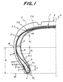
- Fig. 1 shows a diagrammatically left-half section view of an embodiment of the pneumatic radial tire for passenger car according to the invention
- Fig. 2 shows an X-ray photograph schematically illustrating one steel cord and rubber (shown by shadowed region) existing in steel filaments of the cord for the carcass ply
- Fig. 3 shows an X-ray photograph schematically illustrating only the steel cord after the removal of the rubber portion in Fig. 2.
- the pneumatic radial tire for passenger car (herein-after referred to as a tire) 1 comprises a pair of bead portions 2 (only one side is shown), a pair of sidewall portions 3 (only one side is shown), a tread portion 4 extending between the sidewall portions 3, a carcass 6 comprised of at least one rubberized cord ply of a radial arrangement reinforcing the above portions 2, 3, 4 between a pair of bead cores 5 embedded in the bead portions 2, two plies in the illustrated embodiment, and a belt 7 reinforcing the tread portion 4 on the outer periphery of the carcass 6.
- the carcass 6 of the illustrated embodiment are comprised of a turnup ply 6-1 wound around the bead core 5 from inside of the tire 1 toward outside to form a turnup portion 6-1 u and a down ply 6-2 terminated in the vicinity of the bead core 5 at the outside of the turnup ply 6-1.
- the turnup ply 6-1 is an innermost carcass ply.
- there may be taken various ply structures such as only one turnup ply 6-1, combination of two turnup plies and one down ply, combination of one turnup ply and two down plies and the like though the illustration of such a combination is omitted.
- an end 6-1 uE of the turnup portion 6-1 u is located in a zone ranging from a position near to the bead portion 2 to a position of a region of the belt 7 in the tread portion 4.
- the end 6-1 uE of the turnup portion 6-1u in the region of the belt 7 is located between the belt 7 and the ply 6-1 or between the belt 7 and a tread rubber 8.
- the latter type is particularly called as an envelop carcass 6.
- the end 6-1uE of the envelop carcass 6 is located at any position in the region of the belt 7, but it is desirable to be located in the vicinity of an equatorial plane E of the tire as far as possible considering the improvement of bending rigidity in the radial direction of the tire 1.
- the ply cord of the carcass 6 there are a case of using organic fiber cords such as polyester cord, rayon cord and the like, and a case of using steel cord.
- the use of the steel cord is particularly effective to the carcass having the up-down structure of two or more plies and the carcass 6 of one ply. The details of the steel cord are described later.
- the belt 7 is comprised of 2 or more cross cord layers, two cross cord layers in the illustrated embodiment, desirably two cross steel cord layers 7-1, 7-2 and includes an organic fiber cord layer arranged on an outer periphery of the cross layers as shown by dotted lines in Fig. 1, for example, a helically wound layer of 6,6-nylon 7-3.
- the steel cord cross layers 7-1, 7-2 have an arrangement that steel cords of these layers are crossed with each other with respect to an equatorial plane E of the tire, in which the width of the layer 7-1 adjacent to the carcass 6 is wider than the width of the layer 7-2 in the illustrated embodiment.
- the tire 1 is provided at inner face sides of the turnup ply 6-1 of the carcass 6 with a pair of thick reinforcing strip rubbers 8 (only one side is shown) having a crescent shape at their sections inherent to the run-flat tire.
- the reinforcing strip rubber 8 has a shape that a gauge of a central zone in the radial direction of the tire is 8-16 mm and both end portions in the radial direction of the tire are tapered in order to stably support total weight of the vehicle during the running even at an internal pressure of zero to prevent the separation of the tire 1 from the approved rim to thereby prevent the breakage of the tire 1 and further maintain the running stability even at a time of rapid puncture during the running at a high speed of, for example, 80-160 km/h.
- a thick reinforcing strip rubber (not shown) is provided between an outer face of the outermost turnup ply and an inner face of the down ply in addition to the above thick reinforcing strip rubber 8.
- a thick reinforcing strip rubber (not shown) is provided between an innermost down ply and an outermost down ply in addition to the above thick reinforcing strip rubber 8.
- a bead filler rubber 9 taperingly extending outward from an outer peripheral surface of the bead core 5 in the radial direction of the tire is disposed between the turnup ply 6-1 and the down ply 6-2.
- the outer end of the bead filler rubber 9 in the radial direction extends up to at least a position of the maximum tire width.
- the down ply 6-2 takes a form of enveloping the turnup ply 6-1 through the bead filler rubber 9 from the outside thereof. This is the same in case of the two turnup plies.
- the bead filler rubber 9 extends between the main body o the turnup ply 6-1 (ply extending between a pair of the bead cores 5) and the turnup portion 6-1 u along the main body of the ply 6-1 in the same manner as mentioned above.
- numeral 10 is an innerliner made of a halogenated butyl rubber having an air impearmeability.
- the tire 1 is a tubeless tire.
- Each of the reinforcing strip rubber 8 and the bead filler rubber 9 is required to have a JIS A hardness at 25°C of not less than 70 degrees and a rebound resilience at 25°C of not less than 65%. Further, it is required that a ratio Hs(R)/Hs(F) of JIS A hardness Hs(R) of the reinforcing strip rubber 8 to JIS A hardness Hs(F) of the bead filler rubber 9 is within a range of 0.9-1.15.
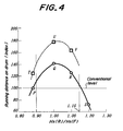
- a maximum gauge G R (details will be described later) and a height in radial direction of tire in the reinforcing strip rubber 8 are 11.0 mm and 135 mm, respectively, and a maximum gauge G F (details will be described later) and a height in radial direction of tire in the bead filler rubber 9 are 6.0 mm and 45 mm, respectively, and the reinforcing strip rubber 8 has a JIS A hardness of 80 degrees and a rebound resilience of 70%, while the ratio Hs(R)/Hs(F) is 4 levels, in which a conventional tire P has a lower limit of 0.88 (value of Hs(F) is 90 degrees), an experimental tire Q has a value of 1.00, an experimental tire R has a value of 1.10, and an experimental tire S has an upper limit of 1.20.
- the comparative evaluation of the run-flat durability is conducted by pushing each of the conventional tire P and the experimental tires Q, R and S on a drum rotating at a peripheral speed of 90 km/h under an internal pressure of zero and a load of 570 kgf corresponding to a total vehicle weight to be mounted with each of these tires P, Q, R and S.
- the evaluation is based on a running distance (km) until the occurrence of tire trouble, which is represented by an index on the basis that the running distance of the conventional tire P is 100.
- the larger the index value the better the tire durability.
- the index value of the experimental tire Q is 140 and that of the experimental tire R is 130, while that of the experimental tire S is only 70.
- the maximum gauge G R of the reinforcing strip rubber 8 of 10.0 mm and the maximum gauge G F of the bead filler rubber G F of 6.0 mm should be regarded to be an upper limit gauge for stopping the increase of tire weight against that of the usual tire weight to minimum as far as possible.
- the test for the run-flat durability on the drum under the same test conditions as mentioned above is conducted as a second experiment by using an experimental tire T corresponding to the conventional tire P, an experimental tire U corresponding to the experimental tire Q and an experimental tire V corresponding to the experimental tire R wherein the JIS A hardness and rebound resilience of the reinforcing strip rubber 8 are 80 degrees and 70%, and the maximum gauge G R of the reinforcing strip rubber 8 is 12.0 mm (height is the same as 135 mm), and the maximum gauge G F of the bead filler rubber 9 is 8.0 mm (height is the same as 45 mm).
- the value of the ratio Hs(R)/Hs(F) is 0.88 in the experimental tire T, 1.00 in the experimental tire U and 1.10 in the experimental tire V.
- the experimental tire T shows 125
- the experimental tires U and V show high levels of 178 and 164, respectively, which proves the reasonability of the first experiment in view of the inclusion of peak point in the experimental tire U.
- index values are by mark ⁇ in Fig. 4 and connected to each other as a smooth curved line (dotted lines).
- a nucleus of ply separation is caused as shown by dotted lines b in Fig. 5, and the ply separation grows outward from the separation nucleus b in the radial direction of the tire and finally cracks are caused in a portion shown by symbol c in Fig. 5 to bring about the breakage of the tire, which is impossible to continue the running.
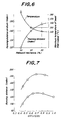
- a left-side ordinate shows the running distance on the basis that the conventional tire P is 100
- a right-side ordinate shows a maximum temperature (°C) inside the bead filler rubber 9.
- the maximum gauge G R (mm) of the full reinforcing strip rubber 8 used herein means that when the carcass 6 comprises two turnup plies and has also a reinforcing strip rubber (not shown) between the two plies, there is used a total value obtained by adding gauges (mm) of these reinforcing strip rubbers, while when the carcass comprises two down plies and also has a reinforcing strip rubber (not shown) between these plies, there is used a total gauge G R (mm) obtained by adding gauges (mm) of these reinforcing strip rubbers.
- the maximum gauge G F (mm) of the full bead filler rubber used herein means a total gauge G F (mm) obtained by adding gauges of bead filler rubber portions even when the bead filler rubber is divided into two or more portions.
- positions of the maximum gauge G R (mm) and the position of the maximum gauge G F (mm) are defined as follows.
- a portion of the maximum gauge G R (mm) is located within a range of sum of heights (h 1 +h 2 ), wherein with respect to a height H (mm) of the position M corresponding to the maximum tire width as measured from a bead base line BL parallel to the rotating axis of the tire and passing through an intersect between an extension line of a bead base Bb and an extension line of a surface of a lower part of the bead portion 2 contacting with a flange of a rim in Fig.
- a height h 1 from a line segment connecting the positions M of the maximum tire width outward in the radial direction of the tire is 0.6H and a height h 2 from the above line segment inward in the radial direction of the tire is 0.3H.
- the maximum gauge G F (mm) as shown in Fig. 1, a maximum height J (mm) as measured from an outer peripheral surface of the bead core outward in the radial direction of the tire is placed within a range corresponding to 0.3 times the height H (mm) of the position M of the maximum tire width.
- the value of the ratio G F /G R is changed while using the same tire size, load condition and peripheral speed as in the first experiment to measure the running distance on the drum at the run-flat state.
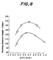
- the results are represented by an index on the basis that the control tire is 100 and shown in Fig. 7.
- gauges G F (mm), G R (mm), ratio G F /G R , index of running distance, various weights (kgf), (index of running distance)/total weight (kgf) and the like are shown in Table 1.
- Table 1 Experiment No. 1 2 3 4 5 6 7 8 9
- Maximum gauge G R (mm) 11.0 11.0 11.0 11.0 11.0 13.0 13.0 13.0 13.0
- Maximum gauge G F (mm) 5.0 6.0 7.0 9.0 11.0 6.0 7.0 9.0 11.0
- Ratio G F /G R 0.45 0.55 0.64 0.82 1.00 0.46 0.54 0.69 0.85
- the steel cord applied to the ply 6-1 (one ply inclusive of envelop) and plies 6-1, 6-2 (up-down structure) in the carcass 6 is described in detail below.
- the steel cord has a twisting structure of 1 x n or 1 + n wherein n is an integer of 2-7.
- a diameter of a steel filament constituting the steel cord is within a range of 0.125-0.275 mm.
- the deflection ratio (%) is represented by a percentage (( ⁇ /SH) x 100) of a value of a ratio of deflection ⁇ (mm) of the tie at the inner pressure of zero under a load of 570 kgf to a tire height SH (mm) when the tire is inflated at an inner pressure of 1.5 kgf/cm 2 corresponding to the load of 570 kgf (according to JATMA YEAR BOOK-1998).
- the measured result of the deflection ratio is 35.0% in the tire W 1 , 37.8% in the tire W 2 and 38.5% in the tire W 3 , respectively.
- the running distance on drum until the occurrence of troubles is represented by an index on the basis that the tire W 2 is 100 and shown in Fig. 9. As seen from Fig. 9, the tire using the steel cord having a high bending rigidity is excellent in the run-flat durability.
- steel cords having a high elongation property that total elongation at break of a cord at a bare state (according to JIS G-3510-1986) is not less than 3.5%, desirably not less than 4.0%. Moreover, such steel cords are desired to have a property based on the following test.
- a ratio of total area of steel filaments occupied in an area of a cord composite excluding a portion projected from an outermost filament (area occupying ratio R) in a length of 15 mm in a longitudinal direction optionally selected from the X-ray photograph of one steel cord-rubber composite, which is taken out from the plies 6-1, 6-2 of the carcass 6, is within a range of 0.45-0.95.
- the length 15 mm in the longitudinal direction of the cord means 15 mm as a cord length in the X-ray photograph.
- the area occupying ratio R is an average of 10 measured values when an X-ray is irradiated to the sidewall portion 3 in the vicinity of a position S of a maximum width of the tire 1 from a direction perpendicular to the surface of the sidewall portion 3 at 10 places in the circumferential direction of the tire by using K-2 model made by Softec Co., Ltd. to obtain 10 X-ray photographs.
- the area occupying ratio R is less than 0.45, a contact area between each filament and rubber increases to more control corrosion propagation through water content, but a tensile modulus as the steel cord becomes too low and hence the bending rigidity required in the carcass 6 can not be satisfied, while when the area occupying ratio R exceeds 0.95, the filament itself hardly deforms and the resistance to compression fatigue is degraded.
- the area occupying ratio R is preferably within a range of 0.50-0.90, more particularly 0.55-0.75.
- the steel cord having an area occupying ratio R of 0.55-0.75 is so-called open twisted cord having a wide space in an inside of an outer cord envelop in which the filaments are substantially independent in rubber matrix and contact with each other in a point at most.
- open twisted steel cord By using such an open twisted steel cord, the run-flat durability can be more improved over a full running distance of the tire 1 because (1) a greater amount of rubber can be penetrated into the inside of the steel cord to increase the bending rigidity of the steel cord and hence the deflection amount ⁇ of the tire 1 during the running at a flat state can be more decreased to more contribute to the improvement of the run-flat durability; (2) the contact area between rubber and each filament in the steel cord is increased to control abrasion due to friction between mutual filaments or fretting and the deterioration of the corrosion resistance of the steel cord due to the fretting can largely be improved; and (3) the increase of the contact area between rubber and each filament controls the penetration of water into a space between the filaments in the steel cord and
- a pneumatic radial tire having a size of 215/65R15 and a structure shown in Fig. 1, wherein the carcass 6 has a two ply structure comprised of a turnup ply 6-1 and a down ply 6-2, each ply being a rubberized ply of radial-arranged rayon cords of 1650 D/2 (1840 dtex/2 in SI), and the belt 7 is comprised of two steel cord cross layers 7-1, 7-2 and a helically wound and rubberized layer 7-3 of nylon-6,6 cords.
- the test for the run-flat durability on a drum is carried out by applying a load of 540 kgf (corresponding to 76% of maximum load capacity described in JATMA YEAR BOOK-1997) to each test tire of Examples 1-6, Conventional Example and Comparative Example under an internal pressure of zero.
- the running distance (km) until the occurrence of failure is measured as a run-flat durability and is represented by an index on the basis that the conventional tire is 100.
- Such an index value is shown in a lower column of Table 2 together with an index of (index of running distance/total weight (kgf), and further the failure position shown in Fig 5 is shown in a lowest column of Table 2 as symbols a-d. The larger the index value, the better the property.
- the tires of Examples 1-6 develop a considerably excellent run-flat durability as compared with those of the conventional tire and comparative tire but also are remarkably superior in the distance/total weight or index value of (index of running distance)/total weight (kgf) to the conventional tire and comparative tire.
- the tire using the steel cord in he carcass ply according to the invention is adaptable to applications capable of allowing a slight increase of tire weight.
- pneumatic tires capable of developing considerably excellent run-flat durability as compared with the conventional run-flat tire under the same weight as the conventional tire only by specifying values of JIS hardness and rebound resilience in the bead filler rubber and reinforcing strip rubber, specifying the range of hardness ratio between both the rubbers, and further specifying the range of ratio of maximum gauge of the reinforcing strip rubber to maximum gauge of the bead filler rubber while applying the organic fiber cord or the steel cord to the carcass ply.
Abstract
Description
- This invention relates to a pneumatic tire, and more particularly to a pneumatic radial tire of so-called run-flat type capable of running over a given distance at a state that an internal pressure is zero or slight near to zero due to puncture or the like and having particularly an excellent run-flat durability (running at a puncture state).
- A run-flat type radial tire (hereinafter referred to as a run-flat tire) is mainly used in vehicles such as passenger cars or the like in which a load applied to the tire is relatively small, and is required to satisfy a condition that even if the tire is suddenly punctured during the running of the vehicle on a general-purpose road or on an expressway at a high speed, the vehicle, particularly the passenger car can safely be run without damaging the steering stability and hence it can safely and surely be run up to a place capable of exchanging the tire over a given distance, for example, 80-160 km without separating the tire out from the used rim (approved rim) even in the continuity of the running and breaking the tire.
- For this end, the run-flat tires having various structures are proposed, occasionally, in a combination with a fully worked-out special rim. However, the combination with the special rim is too expensive and is lacking in the general-purpose use, but does not contribute to directly or indirectly improve the tire durability to an expected extent though there is recognized an effect of preventing the separation of the tire from the rim. Therefore, the run-flat tire itself will be described with reference to examples below.
- In JP-A-55-68406 is proposed a pneumatic safety tire having an excellent running durability at puncture wherein a pair of thick rubber reinforcements having a crescent shape at its section is arranged in an inner face of a portion of an innermost carcass ply located over a zone ranging from a bead portion through a sidewall portion to an end of a tread portion or between portions of carcass plies and has a JIS hardness of at least 70 degrees, a tensile stress M25 of not less than 10 kgf/cm2 after an aging test in an inert environment of 140°C ± 1°C for 24 hours, and a rebound resilience of not less than 65% through a Dunlop tripsometer.
- In JP-A-1-278806 is proposed a safety tire wherein a sidewall reinforcing rubber layer having a crescent shape at its section is arranged in an inner face of a sidewall portion and divided into inner layer portion, middle layer portion and outer layer portion in a rotating axial direction of the tire, and a soft rubber having a Shore A hardness of 50-70° and a modulus at 100% elongation of 10-30 kgf/cm2 is applied to each of the inner and outer layer portions, and a hard rubber having a Shore A hardness of 70-90° and a modulus at 100% elongation of 30-70 kgf/cm2 is applied to the middle layer portion, and a bead apex rubber having a Shore A hardness of 74-95° is further arranged.
- In JP-A-3-176213 is proposed a run-flat pneumatic radial tire wherein a carcass has an up-down structure of 2 plies, and a reinforcing liner layer having a crescent shape at its section and made of rubber having a 100% modulus of not less than 60 kgf/cm2 and a loss tangent at 100°C of not more than 0.35 is arranged inside the carcass ply in a sidewall portion, and a bead filler rubber having a JIS hardness of 60-80 degrees is further arranged.
- In JP-A-4-345505 is proposed a pneumatic safety tire comprising carcass plies of up-down structure wherein a thick reinforcing rubber having a crescent shape at its section and divided into a first inner reinforcing rubber layer and a second outer reinforcing rubber layer in a radial direction of the tire is arranged in an inner face of an inner carcass in a sidewall portion and a bead filler rubber is further arranged, and Shore A hardnesses of these rubbers are made higher in order of the first reinforcing rubber layer, second reinforcing rubber layer and the bead filler rubber.
- Among the aforementioned various proposals, the run-flat tire having an excellent cost performance and hence being put into practice in market at most is a pneumatic radial tire comprising radial carcass plies of up-down structure developing an effect of mitigating degree of collapse deformation during the running at the flat state as far as possible, a pair of thick reinforcing rubber of hard and soft strips disposed at an inner face side of an innermost turnup ply from a position near to a bead core in a bead portion through a sidewall portion to an end of a tread portion and having a crescent shape at its section, and a hard bead filler rubber enveloped between turnup ply and down ply and extending from an outer peripheral face of the bead core up to a position near to a maximum width of the tire. The term "up-down structure" used herein means a ply structure of 2 or more plies comprising a turnup ply wound around a bead core from inside of the tire toward outside thereof and a down ply enveloping the turnup ply form the outside. In such a tire, a rubberized layer of Kevlar cords or steel cords (called as an insert ply) may be arranged in a zone ranging from the bead portion to the sidewall portion.
- This type of the tire is unavoidable to become higher in the cost as compared with general-purpose tires and is frequently used in any expensive vehicles such as sport car, sport-type car, high-grade passenger car and the like. Therefore, the run-flat tire mainly applies to a low-section profile tire having an aspect ratio of not more than 55.
- Even in the tires having the above structures proposed in the aforementioned articles, however, if the internal pressure is rapidly rendered into zero, the steering stability in the vehicle run at a high speed is sufficiently ensured, but it can be said that the high-speed running continuity at the run-flat state and the durability in the long-distance running are still insufficient. Therefore, it is desired to develop tires more improving the run-flat durability while ensuring a low cost as far as possible.
- A main trouble form relating to the run-flat durability, which has been observed up to the present, is that as the running at the flat state proceeds, a nucleus for separation failure is caused between the bead filler rubber and the turnup ply (inner ply) neat to the bead portion, and then the separation nucleus grows up to the position of maximum width in the sidewall portion, and hence a remarkably large crack is caused in the thick reinforcing strip rubber located slightly outward from the maximum width position toward the tread portion to finally cause the tire breakage not conducting the running continuity.
- It is, therefore, an object of the invention to provide a pneumatic tire not only guaranteeing the safe running of a vehicle such as passenger car or the like at a time of causing rapid air removal due to puncture or the like but also improving the tire durability continuously running at the flat state to an extent satisfied by users as a run-flat tire.
- According to the invention, there is the provision of a pneumatic tire comprising a carcass comprised of at least one rubberized cord ply of a radial arrangement reinforcing a pair of sidewall portions and a tread portion between a pair of bead cores embedded in a pair of bead portions, a belt comprised of two or more cross cord layers reinforcing the tread portion on an outer periphery of the carcass and a pair of thick reinforcing strip rubbers having a crescent shape at section thereof and located at an inner face side of an innermost carcass ply so as to extend from a position near to the bead core through the sidewall portion to an end of the tread portion, an improvement wherein each of the bead filler rubber and the reinforcing strip rubber has a JIS A hardness at 25°C of not less than 70 degrees and a rebound resilience at 25°C of not less than 65% and a ratio of JIS A hardness of the reinforcing strip rubber (Hs(R)) to JIS A hardness of the bead filler rubber (Hs(F)) is within a range of 0.9-1.15.
- The term "carcass" used herein includes a case that the carcass comprises only a turnup ply wound around the bead core from inside of the tire toward outside thereof and a case that the carcass comprises the turnup ply and a down ply enveloping the turnup ply together with a bead filler rubber from the outside of the turnup ply (two or more carcass plies). In case of the turnup ply, there are included a case that the turnup end is located in a zone ranging from the bead portion to the sidewall portion, a case that the turnup end is located between the belt and the outermost carcass ply in the tread portion (so-called first envelop structure), and a case that the turnup end is located at the outside of the belt in the radial direction of the tire (so-called second envelop structure).
- As the cord for the carcass ply, use may be made of organic fiber cords such as polyester cord, rayon cord or the like, and inorganic fiber cords such as steel cord or the like. The detail of the steel cord will be mentioned later.
- The measurements of JIS A hardness and rebound resilience are according to Spring Type Hardness Test (Type A) in "Hardness Test" and "Rebound Resilience Test" described on "Physical Testing Methods for Vulcanized Rubber" of JIS K6301-1995, respectively.
- In preferable embodiment of the invention, it is practically effective to define a relationship between the bead filler rubber gauge and the reinforcing strip rubber gauge. That is, a ratio of maximum gauge GF (mm) of full bead filler rubber as measured in a normal direction drawn to an outer surface of the innermost carcass ply in the vicinity of the outer periphery of the bead core to maximum gauge GR (mm) of full reinforcing strip rubber as measured in a normal direction drawn to an inner surface of the innermost carcass ply in the vicinity of the maximum width position of the tire is within a range of 0.5-0.9.
- The invention will be described with reference to the accompanying drawings, wherein:
- Fig. 1 is a diagrammatically left-side section view of an embodiment of the pneumatic tire according to the invention;
- Fig. 2 is an X-ray photograph schematically illustrating one rubberized steel cord for the carcass ply;
- Fig. 3 is an X-ray photograph schematically illustrating only the steel cord shown in Fig. 2;
- Fig. 4 is a graph showing a relationship between ratio of hardness of reinforcing strip rubber to hardness of bead filler rubber and running distance on drum;
- Fig. 5 is a diagrammatically left-side section view illustrating trouble places of the tire shown in Fig. 1;
- Fig. 6 is a graph showing a relationship among rebound resilience, running distance on drum and maximum temperature of bead filler rubber;
- Fig. 7 is a graph showing a relationship between ratio of maximum gauge of reinforcing strip rubber to maximum gauge of bead filler rubber and running distance on drum;
- Fig. 8 is a graph showing values obtained by dividing the running distance on drum shown in Fig. 5 by total weight of reinforcing strip rubber and bead filler rubber; and
- Fig. 9 is a graph showing a relation between flexing ratio and run-flat durability.
-
- Fig. 1 shows a diagrammatically left-half section view of an embodiment of the pneumatic radial tire for passenger car according to the invention, Fig. 2 shows an X-ray photograph schematically illustrating one steel cord and rubber (shown by shadowed region) existing in steel filaments of the cord for the carcass ply, and Fig. 3 shows an X-ray photograph schematically illustrating only the steel cord after the removal of the rubber portion in Fig. 2.
- In Fig. 1, the pneumatic radial tire for passenger car (herein-after referred to as a tire) 1 comprises a pair of bead portions 2 (only one side is shown), a pair of sidewall portions 3 (only one side is shown), a
tread portion 4 extending between thesidewall portions 3, acarcass 6 comprised of at least one rubberized cord ply of a radial arrangement reinforcing theabove portions bead cores 5 embedded in thebead portions 2, two plies in the illustrated embodiment, and abelt 7 reinforcing thetread portion 4 on the outer periphery of thecarcass 6. - The
carcass 6 of the illustrated embodiment are comprised of a turnup ply 6-1 wound around thebead core 5 from inside of thetire 1 toward outside to form a turnup portion 6-1 u and a down ply 6-2 terminated in the vicinity of thebead core 5 at the outside of the turnup ply 6-1. In the up-down carcass 6 of the illustrated embodiment, the turnup ply 6-1 is an innermost carcass ply. As thecarcass 6, however, there may be taken various ply structures such as only one turnup ply 6-1, combination of two turnup plies and one down ply, combination of one turnup ply and two down plies and the like though the illustration of such a combination is omitted. - When the
carcass 6 is comprised of only one turnup ply 6-1, an end 6-1 uE of the turnup portion 6-1 u is located in a zone ranging from a position near to thebead portion 2 to a position of a region of thebelt 7 in thetread portion 4. The end 6-1 uE of the turnup portion 6-1u in the region of thebelt 7 is located between thebelt 7 and the ply 6-1 or between thebelt 7 and atread rubber 8. The latter type is particularly called as anenvelop carcass 6. The end 6-1uE of theenvelop carcass 6 is located at any position in the region of thebelt 7, but it is desirable to be located in the vicinity of an equatorial plane E of the tire as far as possible considering the improvement of bending rigidity in the radial direction of thetire 1. - As the ply cord of the
carcass 6, there are a case of using organic fiber cords such as polyester cord, rayon cord and the like, and a case of using steel cord. The use of the steel cord is particularly effective to the carcass having the up-down structure of two or more plies and thecarcass 6 of one ply. The details of the steel cord are described later. - The
belt 7 is comprised of 2 or more cross cord layers, two cross cord layers in the illustrated embodiment, desirably two cross steel cord layers 7-1, 7-2 and includes an organic fiber cord layer arranged on an outer periphery of the cross layers as shown by dotted lines in Fig. 1, for example, a helically wound layer of 6,6-nylon 7-3. The steel cord cross layers 7-1, 7-2 have an arrangement that steel cords of these layers are crossed with each other with respect to an equatorial plane E of the tire, in which the width of the layer 7-1 adjacent to thecarcass 6 is wider than the width of the layer 7-2 in the illustrated embodiment. - And also, the
tire 1 is provided at inner face sides of the turnup ply 6-1 of thecarcass 6 with a pair of thick reinforcing strip rubbers 8 (only one side is shown) having a crescent shape at their sections inherent to the run-flat tire. The reinforcingstrip rubber 8 has a shape that a gauge of a central zone in the radial direction of the tire is 8-16 mm and both end portions in the radial direction of the tire are tapered in order to stably support total weight of the vehicle during the running even at an internal pressure of zero to prevent the separation of thetire 1 from the approved rim to thereby prevent the breakage of thetire 1 and further maintain the running stability even at a time of rapid puncture during the running at a high speed of, for example, 80-160 km/h. - In case of the
tire 1 having thecarcass 6 comprised of two turnup plies and one down ply, a thick reinforcing strip rubber (not shown) is provided between an outer face of the outermost turnup ply and an inner face of the down ply in addition to the above thick reinforcingstrip rubber 8. On the other hand, in case of thetire 1 having the carcass comprised of one turnup ply and two down plies, a thick reinforcing strip rubber (not shown) is provided between an innermost down ply and an outermost down ply in addition to the above thick reinforcingstrip rubber 8. - In addition to the
reinforcing strip rubber 8, abead filler rubber 9 taperingly extending outward from an outer peripheral surface of thebead core 5 in the radial direction of the tire is disposed between the turnup ply 6-1 and the down ply 6-2. The outer end of thebead filler rubber 9 in the radial direction extends up to at least a position of the maximum tire width. Thus, the down ply 6-2 takes a form of enveloping the turnup ply 6-1 through thebead filler rubber 9 from the outside thereof. This is the same in case of the two turnup plies. In thetire 1 having thecarcass 6 of one ply, thebead filler rubber 9 extends between the main body o the turnup ply 6-1 (ply extending between a pair of the bead cores 5) and the turnup portion 6-1 u along the main body of the ply 6-1 in the same manner as mentioned above. Moreover,numeral 10 is an innerliner made of a halogenated butyl rubber having an air impearmeability. In this case, thetire 1 is a tubeless tire. - Each of the reinforcing
strip rubber 8 and thebead filler rubber 9 is required to have a JIS A hardness at 25°C of not less than 70 degrees and a rebound resilience at 25°C of not less than 65%. Further, it is required that a ratio Hs(R)/Hs(F) of JIS A hardness Hs(R) of the reinforcingstrip rubber 8 to JIS A hardness Hs(F) of thebead filler rubber 9 is within a range of 0.9-1.15. - The reason why the above rubber properties and the ratio Hs(R)/Hs(F) are restricted to the above ranges will be described based on experimental results using a tire having a size of 225/60R16 as a representation of the passenger car tire below. This tire has a structure shown in Fig. 1 and polyester cords are used in the plies 6-1, 6-2 of the
carcass 6. - In a first experiment, a maximum gauge GR (details will be described later) and a height in radial direction of tire in the reinforcing
strip rubber 8 are 11.0 mm and 135 mm, respectively, and a maximum gauge GF (details will be described later) and a height in radial direction of tire in thebead filler rubber 9 are 6.0 mm and 45 mm, respectively, and the reinforcingstrip rubber 8 has a JIS A hardness of 80 degrees and a rebound resilience of 70%, while the ratio Hs(R)/Hs(F) is 4 levels, in which a conventional tire P has a lower limit of 0.88 (value of Hs(F) is 90 degrees), an experimental tire Q has a value of 1.00, an experimental tire R has a value of 1.10, and an experimental tire S has an upper limit of 1.20. - The comparative evaluation of the run-flat durability is conducted by pushing each of the conventional tire P and the experimental tires Q, R and S on a drum rotating at a peripheral speed of 90 km/h under an internal pressure of zero and a load of 570 kgf corresponding to a total vehicle weight to be mounted with each of these tires P, Q, R and S. The evaluation is based on a running distance (km) until the occurrence of tire trouble, which is represented by an index on the basis that the running distance of the conventional tire P is 100. The larger the index value, the better the tire durability. As a result, the index value of the experimental tire Q is 140 and that of the experimental tire R is 130, while that of the experimental tire S is only 70. These index values are shown by mark ○ in Fig. 4 and connected to each other as a smooth curved line.
- As seen from Fig. 4, in order to obtain the run-flat durability exceeding that of the conventional tire P, it is required that the value of the ratio Hs(R)/Hs(F) is within a range of 0.9-1.15.
- The maximum gauge GR of the reinforcing
strip rubber 8 of 10.0 mm and the maximum gauge GF of the bead filler rubber GF of 6.0 mm should be regarded to be an upper limit gauge for stopping the increase of tire weight against that of the usual tire weight to minimum as far as possible. In order to ascertain universality of the first experiment, the test for the run-flat durability on the drum under the same test conditions as mentioned above is conducted as a second experiment by using an experimental tire T corresponding to the conventional tire P, an experimental tire U corresponding to the experimental tire Q and an experimental tire V corresponding to the experimental tire R wherein the JIS A hardness and rebound resilience of the reinforcingstrip rubber 8 are 80 degrees and 70%, and the maximum gauge GR of the reinforcingstrip rubber 8 is 12.0 mm (height is the same as 135 mm), and the maximum gauge GF of thebead filler rubber 9 is 8.0 mm (height is the same as 45 mm). - The value of the ratio Hs(R)/Hs(F) is 0.88 in the experimental tire T, 1.00 in the experimental tire U and 1.10 in the experimental tire V. As a result of this test representing the running distance on the drum by an index on the basis that the conventional tire P is 100, the experimental tire T shows 125, while the experimental tires U and V show high levels of 178 and 164, respectively, which proves the reasonability of the first experiment in view of the inclusion of peak point in the experimental tire U. These index values are by mark □ in Fig. 4 and connected to each other as a smooth curved line (dotted lines).
- Referring to Fig. 5, in the conventional tire P and the experimental tire T, strain concentrates between the
bead filler rubber 9 having a higher rigidity and the turnup ply 6-1 of thecarcass 6 because the hardness Hs(F) of thebead filler rubber 9 is largely harder than the hardness Hs(R) of the reinforcingstrip rubber 8 as the value of the ratio Hs(R)/Hs(F) is 0.88. As a result, it has been confirmed that a nucleus of ply separation is caused as shown by dotted lines b in Fig. 5, and the ply separation grows outward from the separation nucleus b in the radial direction of the tire and finally cracks are caused in a portion shown by symbol c in Fig. 5 to bring about the breakage of the tire, which is impossible to continue the running. - On the other hand, as shown in the experimental tire S, when the hardness Hs(R) of the reinforcing
strip rubber 8 is too harder over the limit as compared with the hardness Hs(F) of thebead filler rubber 9, the rigidity of the reinforcingstrip rubber 8 is largely higher than the rigidity of thebead filler rubber 9, so that strain concentrates between the reinforcingstrip rubber 8 and the turnup ply 6-1 of thecarcass 6. Consequently, a nucleus of ply separation is caused at a position a shown by dotted lines in Fig. 5, and the ply separation grows outside from the separation nucleus a in the radial direction of the tire likewise the above case and finally cracks are caused in a portion shown by symbol c in Fig. 5 to bring about the breakage of the tire, which is impossible to continue the running. - When the difference of rigidity between the reinforcing
strip rubber 8 and thebead filler rubber 9 sandwiching the turnup ply 6-1 is large during the running of thetire 1 at a flat state under loading, divergence is caused between themutual rubbers - On the other hand, in case of the experimental tires Q, R, U, V, the hardness Hs(R) of the reinforcing
strip rubber 8 and the hardness Hs(F) of thebead filler rubber 9 are maintained at a proper balancing state, so that a proper rigidity distribution is attained between themutual rubbers - When the
tire 1 is run at the flat state under loading, opposed portions of the reinforcingstrip rubber 8 and thebead filler rubber 9 sandwiching the turnup ply 6-1 are apt to be high temperature due to the increase of heat generation quantity, so that it is particularly important to prevent blow-out failure of thebead filler rubber 9 due to such a high temperature. As a third experiment, the running distance on the drum and maximum temperature (°C) inside thebead filler rubber 9 are measured under the same conditions as in the first experiment by using atire 1 provided with abead filler rubber 9 having three kinds of rebound resilience at 25°C of 50%, 65% and 80% as represented by the experimental tire Q. The results are shown in Fig. 6. - In Fig. 6, a left-side ordinate shows the running distance on the basis that the conventional tire P is 100, and a right-side ordinate shows a maximum temperature (°C) inside the
bead filler rubber 9. As seen from Fig. 6, when the rebound resilience is less than 65%, the degree of decreasing the running distance on the drum is remarkable and also the temperature rising degree of thebead filler rubber 9 is conspicuous. In order to prevent the blow-out failure of thebead filler rubber 9 due to the higher temperature, it is required to restrict the maximum temperature to not higher than 150°C, while in order to ensure the running distance on the drum of not less than 140 as an index value, it is required to restrict the rebound resilience of thebead filler rubber 9 to not less than 65%. Of course, this is applied to the case of the reinforcingstrip rubber 8 though the illustration is omitted. - Although the above is described with respect to one kind of the
passenger car tire 1, when the same experiments are repeated to the other various sizes of the tire, all of the results are the same as described above. As to at leastpassenger car tire 1, therefore, the run-flat durability of the tire is largely improved when each of the reinforcingstrip rubber 8 and thebead filler rubber 9 has a JIS A hardness at 25°C of not less than 70 degrees and a rebound resilience at 25°C of not less than 65%, and the ratio Hs(R)/Hs(F) of hardness Hs(R) of the reinforcingstrip rubber 8 to hardness Hs(F) of thebead filler rubber 9 is within a range of 0.9-1.15. - Referring to Fig. 1, it is practically effective to more improve the run-flat durability when the ratio GF/GR of maximum gauge GF (mm) of full
bead filler rubber 9 as measured in a normal direction drawn to an outer surface of an innermost turnup ply 6-1 in the vicinity of thebead core 5 to maximum gauge GR (mm) of full reinforcingstrip rubber 8 as measured in a normal direction drawn to an inner surface of the innermost turnup ply 6-1 in the vicinity of a line segment connecting positions M of a maximum tire width (only one side is shown) is within a rage of 0.5-0.9. - The maximum gauge GR (mm) of the full reinforcing
strip rubber 8 used herein means that when thecarcass 6 comprises two turnup plies and has also a reinforcing strip rubber (not shown) between the two plies, there is used a total value obtained by adding gauges (mm) of these reinforcing strip rubbers, while when the carcass comprises two down plies and also has a reinforcing strip rubber (not shown) between these plies, there is used a total gauge GR (mm) obtained by adding gauges (mm) of these reinforcing strip rubbers. The maximum gauge GF (mm) of the full bead filler rubber used herein means a total gauge GF (mm) obtained by adding gauges of bead filler rubber portions even when the bead filler rubber is divided into two or more portions. - It is favorable that positions of the maximum gauge GR (mm) and the position of the maximum gauge GF (mm) are defined as follows. As to the position of maximum gauge GR (mm), a portion of the maximum gauge GR (mm) is located within a range of sum of heights (h1+h2), wherein with respect to a height H (mm) of the position M corresponding to the maximum tire width as measured from a bead base line BL parallel to the rotating axis of the tire and passing through an intersect between an extension line of a bead base Bb and an extension line of a surface of a lower part of the
bead portion 2 contacting with a flange of a rim in Fig. 1, a height h1 from a line segment connecting the positions M of the maximum tire width outward in the radial direction of the tire is 0.6H and a height h2 from the above line segment inward in the radial direction of the tire is 0.3H. Then, as to the maximum gauge GF (mm), as shown in Fig. 1, a maximum height J (mm) as measured from an outer peripheral surface of the bead core outward in the radial direction of the tire is placed within a range corresponding to 0.3 times the height H (mm) of the position M of the maximum tire width. - In the running of the
tire 1 at the flat state under loading, when the ratio GF/GR is less than 0.5, the degree of flex deformation of thebead filler rubber 9 in the vicinity of symbol d (see Fig. 5) is larger than the degree of flex deformation of the reinforcingstrip rubber 8 in the vicinity of symbol c (see Fig. 5), and hence a premature failure is caused in thebead filler rubber 9 near to the symbol d. While, when the ratio GF/GR exceeds 0.9, the degree of flex deformation of the reinforcingstrip rubber 8 in the vicinity of symbol c is larger than the degree of flex deformation of thebead filler rubber 9 in the vicinity of symbol d, and hence a premature failure is caused in the reinforcingstrip rubber 8 near to the symbol c. - On the contrary, when the ratio GF/GR is within a range of 0.5-0.9, the degree of flex deformation of the reinforcing
strip rubber 8 in the vicinity of symbol c is properly balanced with the degree of flex deformation of thebead filler rubber 9 in the vicinity of symbol d, whereby the run-flat running distance is made longest. This means that strain becomes substantially equal between the reinforcingstrip rubber 8 near to the symbol c and thebead filler rubber 9 near to the symbol d and trouble of rubber in the vicinity of the symbol c and trouble of rubber in the vicinity of the symbol d are caused substantially at the same time. - As a fourth experiment, the value of the ratio GF/GR is changed while using the same tire size, load condition and peripheral speed as in the first experiment to measure the running distance on the drum at the run-flat state. The results are represented by an index on the basis that the control tire is 100 and shown in Fig. 7. Further, values calculated by dividing the index of the run-flat running distance in the changed value of the ratio GF/GR by total weight (kgf) = weight of reinforcing strip rubber 8 (kgf) + weight of bead filler rubber 9 (kgf) are represented by an index on the basis that the control tire is 100 and shown in Fig. 8. In addition, gauges GF (mm), GR (mm), ratio GF/GR, index of running distance, various weights (kgf), (index of running distance)/total weight (kgf) and the like are shown in Table 1.
Experiment No. 1 2 3 4 5 6 7 8 9 Maximum gauge GR (mm) 11.0 11.0 11.0 11.0 11.0 13.0 13.0 13.0 13.0 Maximum gauge GF (mm) 5.0 6.0 7.0 9.0 11.0 6.0 7.0 9.0 11.0 Ratio GF/GR 0.45 0.55 0.64 0.82 1.00 0.46 0.54 0.69 0.85 Running distance (index) 100 120 130 130 120 150 170 186 184 Weight of rubber 8 (kgf) 2.80 2.80 2.80 2.80 2.80 3.31 3.31 3.31 3.31 Weight of rubber 9 (kgf) 0.39 0.47 0.55 0.71 0.86 0.47 0.55 0.71 0.86 Total weight (kgf) 3.19 3.27 3.35 3.51 3.66 3.78 3.86 4.02 4.17 Distance/total weight 31.35 36.70 38.81 37.04 32.79 39.68 44.04 46.27 44.12 Distance/total weight (index) 100.0 117.1 123.8 118.1 104.6 126.6 140.5 147.6 140.8 - The steel cord applied to the ply 6-1 (one ply inclusive of envelop) and plies 6-1, 6-2 (up-down structure) in the
carcass 6 is described in detail below. - The steel cord has a twisting structure of 1 x n or 1 + n wherein n is an integer of 2-7. A diameter of a steel filament constituting the steel cord is within a range of 0.125-0.275 mm.
- As a fifth experiment, there are firstly provided experimental tires W1, W2, W3 having the same structure as the
tire 1 shown in Fig. 1 and the same tire size as in the first experiment, wherein the cord used in the plies 6-1, 6-2 of thecarcass 6 is a steel cord having a twisting structure of 1 × 5 × 0.15 (filament diameter = 0.15 mm) in the tie W1, a rayon cord of 1650D/2 (SI unit: 1840 dtex/2) in the tire W2, and a polyester cord of 1500D/2 (SI unit: 1670 dtex/2) in the tire W3, respectively. Then, a deflection ratio (%) at an inner pressure of zero is measured, and thereafter a running distance on drum until the occurrence of troubles is measured at the inner pressure of zero under a condition that the load and peripheral speed are the same as in the first experiment. - The deflection ratio (%) is represented by a percentage ((δ/SH) x 100) of a value of a ratio of deflection δ (mm) of the tie at the inner pressure of zero under a load of 570 kgf to a tire height SH (mm) when the tire is inflated at an inner pressure of 1.5 kgf/cm2 corresponding to the load of 570 kgf (according to JATMA YEAR BOOK-1998). The measured result of the deflection ratio is 35.0% in the tire W1, 37.8% in the tire W2 and 38.5% in the tire W3, respectively. And also, the running distance on drum until the occurrence of troubles is represented by an index on the basis that the tire W2 is 100 and shown in Fig. 9. As seen from Fig. 9, the tire using the steel cord having a high bending rigidity is excellent in the run-flat durability.
- As the steel cord, it is favorable to use steel cords having a high elongation property that total elongation at break of a cord at a bare state (according to JIS G-3510-1986) is not less than 3.5%, desirably not less than 4.0%. Moreover, such steel cords are desired to have a property based on the following test.
- In Figs. 2 and 3, a ratio of total area of steel filaments occupied in an area of a cord composite excluding a portion projected from an outermost filament (area occupying ratio R) in a length of 15 mm in a longitudinal direction optionally selected from the X-ray photograph of one steel cord-rubber composite, which is taken out from the plies 6-1, 6-2 of the
carcass 6, is within a range of 0.45-0.95. Thelength 15 mm in the longitudinal direction of the cord means 15 mm as a cord length in the X-ray photograph. The area occupying ratio R is represented by - In case of the
carcass 6 of one ply, the area occupying ratio R is an average of 10 measured values when an X-ray is irradiated to thesidewall portion 3 in the vicinity of a position S of a maximum width of thetire 1 from a direction perpendicular to the surface of thesidewall portion 3 at 10 places in the circumferential direction of the tire by using K-2 model made by Softec Co., Ltd. to obtain 10 X-ray photographs. When thecarcass 6 is comprised of two plies, it is difficult to conduct an accurate measurement because the steel cord-rubber composites in these plies overlap with each other, so that after each ply is taken out from thetire 1, the X-ray photograph with respect to the each ply is obtained in the same manner as mentioned above to determine the area occupying ratio R as an average of 10 measured values. - When the area occupying ratio R is less than 0.45, a contact area between each filament and rubber increases to more control corrosion propagation through water content, but a tensile modulus as the steel cord becomes too low and hence the bending rigidity required in the
carcass 6 can not be satisfied, while when the area occupying ratio R exceeds 0.95, the filament itself hardly deforms and the resistance to compression fatigue is degraded. Moreover, the area occupying ratio R is preferably within a range of 0.50-0.90, more particularly 0.55-0.75. - The steel cord having an area occupying ratio R of 0.55-0.75 is so-called open twisted cord having a wide space in an inside of an outer cord envelop in which the filaments are substantially independent in rubber matrix and contact with each other in a point at most. By using such an open twisted steel cord, the run-flat durability can be more improved over a full running distance of the
tire 1 because (1) a greater amount of rubber can be penetrated into the inside of the steel cord to increase the bending rigidity of the steel cord and hence the deflection amount δ of thetire 1 during the running at a flat state can be more decreased to more contribute to the improvement of the run-flat durability; (2) the contact area between rubber and each filament in the steel cord is increased to control abrasion due to friction between mutual filaments or fretting and the deterioration of the corrosion resistance of the steel cord due to the fretting can largely be improved; and (3) the increase of the contact area between rubber and each filament controls the penetration of water into a space between the filaments in the steel cord and hence the corrosion propagation of the steel cord through water can be controlled. - In these examples, there is provided a pneumatic radial tire having a size of 215/65R15 and a structure shown in Fig. 1, wherein the
carcass 6 has a two ply structure comprised of a turnup ply 6-1 and a down ply 6-2, each ply being a rubberized ply of radial-arranged rayon cords of 1650 D/2 (1840 dtex/2 in SI), and thebelt 7 is comprised of two steel cord cross layers 7-1, 7-2 and a helically wound and rubberized layer 7-3 of nylon-6,6 cords. - With respect to tires of Examples 1-6, JIS A hardness Hs(R) of reinforcing
strip rubber 8 and JIS A hardness Hs(F) ofbead filler rubber 9 at 25°C, ratio Hs(R)/Hs(F), rebound resilience RR (%) of reinforcingstrip rubber 8 and rebound resilience RF (%) ofbead filler rubber 9 at 25°C, maximum gauge GR (mm) of reinforcingstrip rubber 8, maximum gauge GF (mm) ofbead filler rubber 9 and ratio GF/GR are shown in Table 2 together with those of the conventional tire and comparative tire. Moreover, the height of the reinforcingstrip rubber 8 in the radial direction of the tire is 140 (mm) and the height of thebead filler rubber 9 in the radial direction of the tire is 47 (mm) in these tires. - The test for the run-flat durability on a drum is carried out by applying a load of 540 kgf (corresponding to 76% of maximum load capacity described in JATMA YEAR BOOK-1997) to each test tire of Examples 1-6, Conventional Example and Comparative Example under an internal pressure of zero. The running distance (km) until the occurrence of failure is measured as a run-flat durability and is represented by an index on the basis that the conventional tire is 100. Such an index value is shown in a lower column of Table 2 together with an index of (index of running distance/total weight (kgf), and further the failure position shown in Fig 5 is shown in a lowest column of Table 2 as symbols a-d. The larger the index value, the better the property. Moreover, (index of running distance)/total weight (kgf) is abbreviated as distance/total weight in Table 2.
Items Conventional Example Comparative Example Example 1 2 3 4 5 6 Hardness of rubber 8, Hs(R) (degree)79 70 79 70 79 79 79 79 Hardness of rubber 9, Hs(F) (degree)90 80 79 70 79 79 79 79 Ratio Hs(R)/Hs(F) 0.88 0.88 1.00 1.00 1.00 1.00 1.00 1.00 Rebound resilience of rubber 8 (%) 65 65 65 80 65 65 65 65 Rebound resilience of rubber 9 (%) 50 65 65 80 65 65 65 65 Maximum gauge GR (mm) 11.0 11.0 11.0 11.0 11.0 11.0 11.0 11.0 Maximum gauge GF (mm) 5.5 5.5 5.5 7.5 5.0 7.5 9.9 11.0 Ratio GF/GR 0.50 0.50 0.50 0.70 0.45 0.70 0.90 1.00 Running distance on drum (index) 100 102 130 170 106 168 160 142 Distance/total weight (index) 100 102 130 164 106 162 151 126 Failure position a a d d, c d d, c d, c c - As seen from the values of running distance on drum (index) or values for the run-flat durability in Table 2, the tires of Examples 1-6 develop a considerably excellent run-flat durability as compared with those of the conventional tire and comparative tire but also are remarkably superior in the distance/total weight or index value of (index of running distance)/total weight (kgf) to the conventional tire and comparative tire.
- Moreover, it has been confirmed that even when the steel cord is applied to only the turnup ply 6-1 or both turnup ply 6-1 and down ply 6-2 in the
carcass 6 of tire 1 (having the same tire size as mentioned above), the run-flat durability and the (index of running distance)/total weight (kgf) are considerably improved likewise the tires of Examples 1-6 as compared with the conventional tire using the same kind of the steel cord ply. Therefore, the tire using the steel cord in he carcass ply according to the invention is adaptable to applications capable of allowing a slight increase of tire weight. - According to the invention, there can be provided pneumatic tires capable of developing considerably excellent run-flat durability as compared with the conventional run-flat tire under the same weight as the conventional tire only by specifying values of JIS hardness and rebound resilience in the bead filler rubber and reinforcing strip rubber, specifying the range of hardness ratio between both the rubbers, and further specifying the range of ratio of maximum gauge of the reinforcing strip rubber to maximum gauge of the bead filler rubber while applying the organic fiber cord or the steel cord to the carcass ply.
Claims (3)
- A pneumatic tire (1) comprising a carcass (6) comprised of at least one rubberized ply of a radial arrangement reinforcing a pair of sidewall portions (3) and a tread portion (4) between a pair of bead cores (5) embedded in a pair of bead portions (2), a belt (7) comprised of two or more cross cord layers (7-1,7-2) reinforcing the tread portion (4) on an outer periphery of the carcass (6), and a pair of reinforcing strip rubbers (8) having a crescent shape in section thereof and located at an inner face side of an innermost carcass ply (6-1) so as to extend from a position near to the bead core through the sidewall portion to an end of the tread portion, characterized in that each of a bead filler rubber (9) and the reinforcing strip rubber (8) has a JIS A hardness at 25°C of not less than 70 degrees and a rebound resilience at 25°C of not less than 65%, and in that a ratio of JIS A hardness of the reinforcing strip rubber (Hs(R)) to JIS A hardness of the bead filler rubber (Hs(F)) is within a range of 0.9-1.15.
- A pneumatic tire as claimed in claim 1, characterized in that the bead filler rubber (9) and the reinforcing strip rubber (8) have such a gauge that a ratio of maximum gauge GF (mm) of full bead filler rubber as measured in a normal direction drawn to an outer surface of the innermost carcass ply in the vicinity of the outer periphery of the bead core (5) to maximum gauge GR (mm) of full reinforcing strip rubber as measured in a normal direction drawn to an inner surface of the innermost carcass ply in the vicinity of the maximum width position of the tire is within a range of 0.5-0.9.
- A pneumatic tire as claimed in claim 1 or 2, characterized in that said carcass (6) comprises a turnup ply (6-1) wound around the bead core (5) from the inside of the tire toward the outside and a down ply (6-2) enveloping a bead filler rubber (9) extending from the bead core toward a tread portion (4) and the turnup ply end terminated in the vicinity of the bead core.
Applications Claiming Priority (2)
| Application Number | Priority Date | Filing Date | Title |
|---|---|---|---|
| JP4677098 | 1998-02-27 | ||
| JP4677098 | 1998-02-27 |
Publications (3)
| Publication Number | Publication Date |
|---|---|
| EP0938986A2 true EP0938986A2 (en) | 1999-09-01 |
| EP0938986A3 EP0938986A3 (en) | 2001-03-14 |
| EP0938986B1 EP0938986B1 (en) | 2005-09-21 |
Family
ID=12756575
Family Applications (1)
| Application Number | Title | Priority Date | Filing Date |
|---|---|---|---|
| EP99301448A Expired - Lifetime EP0938986B1 (en) | 1998-02-27 | 1999-02-26 | Pneumatic tires |
Country Status (4)
| Country | Link |
|---|---|
| US (1) | US6138732A (en) |
| EP (1) | EP0938986B1 (en) |
| DE (1) | DE69927310T2 (en) |
| ES (1) | ES2248963T3 (en) |
Cited By (2)
| Publication number | Priority date | Publication date | Assignee | Title |
|---|---|---|---|---|
| EP1531063A1 (en) * | 2003-11-14 | 2005-05-18 | The Goodyear Tire & Rubber Company | Pneumatic tire |
| EP1741569A3 (en) * | 2005-07-07 | 2007-12-26 | Hankook Tire Co., Ltd. | Self-supporting type pneumatic run-flat tire, and insert and bead rubber composition for run-flat capability |
Families Citing this family (6)
| Publication number | Priority date | Publication date | Assignee | Title |
|---|---|---|---|---|
| US6834696B1 (en) * | 2000-06-29 | 2004-12-28 | Bridgestone/Firestone North American Tire, Llc | Runflat tire with cantilever-like sidewall construction |
| TWI398368B (en) * | 2010-01-29 | 2013-06-11 | Kenda Industry Co Ltd | Tire-free tire |
| CN105705940B (en) * | 2013-11-06 | 2019-08-09 | 不二精工株式会社 | The interconnecting piece inspection method of filler |
| US20160167452A1 (en) * | 2014-12-12 | 2016-06-16 | The Goodyear Tire & Rubber Company | Aircraft tire |
| JP5858181B1 (en) | 2015-01-19 | 2016-02-10 | 横浜ゴム株式会社 | Pneumatic tire |
| JP7154947B2 (en) * | 2018-10-26 | 2022-10-18 | Toyo Tire株式会社 | Pneumatic tire manufacturing method and bead member storage holder |
Citations (7)
| Publication number | Priority date | Publication date | Assignee | Title |
|---|---|---|---|---|
| US4265288A (en) * | 1978-11-20 | 1981-05-05 | Bridgestone Tire Co., Ltd. | Pneumatic safety tire with excellent long-running ability after puncture employing rubber having specifically defined properties for sidewall inserts and tread |
| US5131445A (en) * | 1989-09-08 | 1992-07-21 | The Yokohama Rubber Co., Ltd. | Run-flat pneumatic radial tire |
| EP0545681A1 (en) * | 1991-12-05 | 1993-06-09 | Sumitomo Rubber Industries Limited | Pneumatic safety tyre |
| US5494958A (en) * | 1992-12-30 | 1996-02-27 | Bridgestone Corporation | High modulus low hysteresis rubber compound for pneumatic tires |
| JPH1024714A (en) * | 1996-03-15 | 1998-01-27 | Goodyear Tire & Rubber Co:The | Low-pressure run flat tire for all-terrain universal vehicle |
| EP0822105A2 (en) * | 1996-08-02 | 1998-02-04 | Michelin Recherche Et Technique S.A. | Run flat tire and method of manufacture |
| EP0842795A2 (en) * | 1996-11-13 | 1998-05-20 | BRIDGESTONE/FIRESTONE, Inc. | Pneumatic tyre |
Family Cites Families (2)
| Publication number | Priority date | Publication date | Assignee | Title |
|---|---|---|---|---|
| JP2708772B2 (en) * | 1988-05-02 | 1998-02-04 | 住友ゴム工業株式会社 | Safety tire |
| JP3103391B2 (en) * | 1991-05-22 | 2000-10-30 | 株式会社ブリヂストン | Pneumatic safety tire |
-
1999
- 1999-02-26 DE DE69927310T patent/DE69927310T2/en not_active Expired - Fee Related
- 1999-02-26 US US09/258,141 patent/US6138732A/en not_active Expired - Lifetime
- 1999-02-26 EP EP99301448A patent/EP0938986B1/en not_active Expired - Lifetime
- 1999-02-26 ES ES99301448T patent/ES2248963T3/en not_active Expired - Lifetime
Patent Citations (7)
| Publication number | Priority date | Publication date | Assignee | Title |
|---|---|---|---|---|
| US4265288A (en) * | 1978-11-20 | 1981-05-05 | Bridgestone Tire Co., Ltd. | Pneumatic safety tire with excellent long-running ability after puncture employing rubber having specifically defined properties for sidewall inserts and tread |
| US5131445A (en) * | 1989-09-08 | 1992-07-21 | The Yokohama Rubber Co., Ltd. | Run-flat pneumatic radial tire |
| EP0545681A1 (en) * | 1991-12-05 | 1993-06-09 | Sumitomo Rubber Industries Limited | Pneumatic safety tyre |
| US5494958A (en) * | 1992-12-30 | 1996-02-27 | Bridgestone Corporation | High modulus low hysteresis rubber compound for pneumatic tires |
| JPH1024714A (en) * | 1996-03-15 | 1998-01-27 | Goodyear Tire & Rubber Co:The | Low-pressure run flat tire for all-terrain universal vehicle |
| EP0822105A2 (en) * | 1996-08-02 | 1998-02-04 | Michelin Recherche Et Technique S.A. | Run flat tire and method of manufacture |
| EP0842795A2 (en) * | 1996-11-13 | 1998-05-20 | BRIDGESTONE/FIRESTONE, Inc. | Pneumatic tyre |
Non-Patent Citations (1)
| Title |
|---|
| PATENT ABSTRACTS OF JAPAN vol. 1998, no. 05, 30 April 1998 (1998-04-30) & JP 10 024714 A (GOODYEAR TIRE &RUBBER CO:THE), 27 January 1998 (1998-01-27) & US 5 879 482 A (OARE ET AL.) 9 March 1999 (1999-03-09) * |
Cited By (4)
| Publication number | Priority date | Publication date | Assignee | Title |
|---|---|---|---|---|
| EP1531063A1 (en) * | 2003-11-14 | 2005-05-18 | The Goodyear Tire & Rubber Company | Pneumatic tire |
| US7086440B2 (en) | 2003-11-14 | 2006-08-08 | The Goodyear Tire & Rubber Company | Pneumatic tire with annular reinforcing strip layer |
| US7900672B2 (en) | 2003-11-14 | 2011-03-08 | The Goodyear Tire & Rubber Company | Pneumatic tire with annular reinforcing strip layer |
| EP1741569A3 (en) * | 2005-07-07 | 2007-12-26 | Hankook Tire Co., Ltd. | Self-supporting type pneumatic run-flat tire, and insert and bead rubber composition for run-flat capability |
Also Published As
| Publication number | Publication date |
|---|---|
| DE69927310T2 (en) | 2006-06-29 |
| ES2248963T3 (en) | 2006-03-16 |
| EP0938986B1 (en) | 2005-09-21 |
| US6138732A (en) | 2000-10-31 |
| DE69927310D1 (en) | 2006-02-02 |
| EP0938986A3 (en) | 2001-03-14 |
Similar Documents
| Publication | Publication Date | Title |
|---|---|---|
| KR100548893B1 (en) | An inextensible high temperature resistant runflat tire | |
| JP4971700B2 (en) | Run flat tire | |
| KR100293800B1 (en) | Safety pneumatic tires | |
| EP1867497A1 (en) | Run-flat tire | |
| EP1095797B1 (en) | Pneumatic tire | |
| EP0842795A2 (en) | Pneumatic tyre | |
| US6779573B2 (en) | Pneumatic tires | |
| KR20010013040A (en) | Runflat tire with improved carcass | |
| JP5123587B2 (en) | Run flat tire | |
| JP5180562B2 (en) | Run flat tire | |
| EP0884200B1 (en) | Heavy duty pneumatic radial tyres | |
| EP0953463B1 (en) | Pneumatic tires | |
| US6138732A (en) | Pneumatic tires with run flat reinforcing strip rubber | |
| JP2009137449A (en) | Runflat tire | |
| JP3887478B2 (en) | Pneumatic safety tire | |
| JP4015745B2 (en) | Pneumatic safety tire | |
| KR20220038779A (en) | pneumatic tire | |
| JP4544961B2 (en) | Run flat tire | |
| JP4547334B2 (en) | Pneumatic radial tire | |
| JP4548870B2 (en) | Pneumatic tire | |
| JP5185599B2 (en) | Run flat tire | |
| EP3549787A1 (en) | Rubber cord composite, reinforcing member for tires, and tire using same | |
| JPH11301221A (en) | Pneumatic radial tire | |
| JP3982902B2 (en) | Pneumatic tire | |
| JP2005239070A (en) | Pneumatic tire |
Legal Events
| Date | Code | Title | Description |
|---|---|---|---|
| PUAI | Public reference made under article 153(3) epc to a published international application that has entered the european phase |
Free format text: ORIGINAL CODE: 0009012 |
|
| AK | Designated contracting states |
Kind code of ref document: A2 Designated state(s): DE ES FR GB IT |
|
| AX | Request for extension of the european patent |
Free format text: AL;LT;LV;MK;RO;SI |
|
| PUAL | Search report despatched |
Free format text: ORIGINAL CODE: 0009013 |
|
| AK | Designated contracting states |
Kind code of ref document: A3 Designated state(s): AT BE CH CY DE DK ES FI FR GB GR IE IT LI LU MC NL PT SE |
|
| AX | Request for extension of the european patent |
Free format text: AL;LT;LV;MK;RO;SI |
|
| 17P | Request for examination filed |
Effective date: 20010315 |
|
| AKX | Designation fees paid |
Free format text: DE ES FR GB IT |
|
| 17Q | First examination report despatched |
Effective date: 20030124 |
|
| GRAP | Despatch of communication of intention to grant a patent |
Free format text: ORIGINAL CODE: EPIDOSNIGR1 |
|
| GRAS | Grant fee paid |
Free format text: ORIGINAL CODE: EPIDOSNIGR3 |
|
| GRAA | (expected) grant |
Free format text: ORIGINAL CODE: 0009210 |
|
| AK | Designated contracting states |
Kind code of ref document: B1 Designated state(s): DE ES FR GB IT |
|
| REG | Reference to a national code |
Ref country code: GB Ref legal event code: FG4D |
|
| REF | Corresponds to: |
Ref document number: 69927310 Country of ref document: DE Date of ref document: 20051027 Kind code of ref document: P |
|
| REF | Corresponds to: |
Ref document number: 69927310 Country of ref document: DE Date of ref document: 20060202 Kind code of ref document: P |
|
| REG | Reference to a national code |
Ref country code: ES Ref legal event code: FG2A Ref document number: 2248963 Country of ref document: ES Kind code of ref document: T3 |
|
| ET | Fr: translation filed | ||
| PLBE | No opposition filed within time limit |
Free format text: ORIGINAL CODE: 0009261 |
|
| STAA | Information on the status of an ep patent application or granted ep patent |
Free format text: STATUS: NO OPPOSITION FILED WITHIN TIME LIMIT |
|
| 26N | No opposition filed |
Effective date: 20060622 |
|
| PGFP | Annual fee paid to national office [announced via postgrant information from national office to epo] |
Ref country code: ES Payment date: 20080226 Year of fee payment: 10 |
|
| PGFP | Annual fee paid to national office [announced via postgrant information from national office to epo] |
Ref country code: IT Payment date: 20080226 Year of fee payment: 10 Ref country code: GB Payment date: 20080220 Year of fee payment: 10 Ref country code: DE Payment date: 20080221 Year of fee payment: 10 |
|
| PGFP | Annual fee paid to national office [announced via postgrant information from national office to epo] |
Ref country code: FR Payment date: 20080208 Year of fee payment: 10 |
|
| GBPC | Gb: european patent ceased through non-payment of renewal fee |
Effective date: 20090226 |
|
| REG | Reference to a national code |
Ref country code: FR Ref legal event code: ST Effective date: 20091030 |
|
| PG25 | Lapsed in a contracting state [announced via postgrant information from national office to epo] |
Ref country code: DE Free format text: LAPSE BECAUSE OF NON-PAYMENT OF DUE FEES Effective date: 20090901 |
|
| REG | Reference to a national code |
Ref country code: ES Ref legal event code: FD2A Effective date: 20090227 |
|
| PG25 | Lapsed in a contracting state [announced via postgrant information from national office to epo] |
Ref country code: GB Free format text: LAPSE BECAUSE OF NON-PAYMENT OF DUE FEES Effective date: 20090226 Ref country code: FR Free format text: LAPSE BECAUSE OF NON-PAYMENT OF DUE FEES Effective date: 20090302 |
|
| PG25 | Lapsed in a contracting state [announced via postgrant information from national office to epo] |
Ref country code: ES Free format text: LAPSE BECAUSE OF NON-PAYMENT OF DUE FEES Effective date: 20090227 |
|
| PG25 | Lapsed in a contracting state [announced via postgrant information from national office to epo] |
Ref country code: IT Free format text: LAPSE BECAUSE OF NON-PAYMENT OF DUE FEES Effective date: 20090226 |