EP0939002A2 - Motor vehicle display system and ranging device - Google Patents
Motor vehicle display system and ranging device Download PDFInfo
- Publication number
- EP0939002A2 EP0939002A2 EP99108812A EP99108812A EP0939002A2 EP 0939002 A2 EP0939002 A2 EP 0939002A2 EP 99108812 A EP99108812 A EP 99108812A EP 99108812 A EP99108812 A EP 99108812A EP 0939002 A2 EP0939002 A2 EP 0939002A2
- Authority
- EP
- European Patent Office
- Prior art keywords
- vehicle
- display system
- indicator
- deceleration
- signal
- Prior art date
- Legal status (The legal status is an assumption and is not a legal conclusion. Google has not performed a legal analysis and makes no representation as to the accuracy of the status listed.)
- Withdrawn
Links
Images


Classifications
-
- G—PHYSICS
- G01—MEASURING; TESTING
- G01S—RADIO DIRECTION-FINDING; RADIO NAVIGATION; DETERMINING DISTANCE OR VELOCITY BY USE OF RADIO WAVES; LOCATING OR PRESENCE-DETECTING BY USE OF THE REFLECTION OR RERADIATION OF RADIO WAVES; ANALOGOUS ARRANGEMENTS USING OTHER WAVES
- G01S15/00—Systems using the reflection or reradiation of acoustic waves, e.g. sonar systems
- G01S15/88—Sonar systems specially adapted for specific applications
- G01S15/93—Sonar systems specially adapted for specific applications for anti-collision purposes
- G01S15/931—Sonar systems specially adapted for specific applications for anti-collision purposes of land vehicles
-
- B—PERFORMING OPERATIONS; TRANSPORTING
- B60—VEHICLES IN GENERAL
- B60Q—ARRANGEMENT OF SIGNALLING OR LIGHTING DEVICES, THE MOUNTING OR SUPPORTING THEREOF OR CIRCUITS THEREFOR, FOR VEHICLES IN GENERAL
- B60Q1/00—Arrangement of optical signalling or lighting devices, the mounting or supporting thereof or circuits therefor
- B60Q1/26—Arrangement of optical signalling or lighting devices, the mounting or supporting thereof or circuits therefor the devices being primarily intended to indicate the vehicle, or parts thereof, or to give signals, to other traffic
- B60Q1/44—Arrangement of optical signalling or lighting devices, the mounting or supporting thereof or circuits therefor the devices being primarily intended to indicate the vehicle, or parts thereof, or to give signals, to other traffic for indicating braking action or preparation for braking, e.g. by detection of the foot approaching the brake pedal
- B60Q1/444—Arrangement of optical signalling or lighting devices, the mounting or supporting thereof or circuits therefor the devices being primarily intended to indicate the vehicle, or parts thereof, or to give signals, to other traffic for indicating braking action or preparation for braking, e.g. by detection of the foot approaching the brake pedal with indication of the braking strength or speed changes, e.g. by changing shape or intensity of the indication
-
- B—PERFORMING OPERATIONS; TRANSPORTING
- B60—VEHICLES IN GENERAL
- B60Q—ARRANGEMENT OF SIGNALLING OR LIGHTING DEVICES, THE MOUNTING OR SUPPORTING THEREOF OR CIRCUITS THEREFOR, FOR VEHICLES IN GENERAL
- B60Q1/00—Arrangement of optical signalling or lighting devices, the mounting or supporting thereof or circuits therefor
- B60Q1/26—Arrangement of optical signalling or lighting devices, the mounting or supporting thereof or circuits therefor the devices being primarily intended to indicate the vehicle, or parts thereof, or to give signals, to other traffic
- B60Q1/50—Arrangement of optical signalling or lighting devices, the mounting or supporting thereof or circuits therefor the devices being primarily intended to indicate the vehicle, or parts thereof, or to give signals, to other traffic for indicating other intentions or conditions, e.g. request for waiting or overtaking
- B60Q1/52—Arrangement of optical signalling or lighting devices, the mounting or supporting thereof or circuits therefor the devices being primarily intended to indicate the vehicle, or parts thereof, or to give signals, to other traffic for indicating other intentions or conditions, e.g. request for waiting or overtaking for indicating emergencies
-
- B—PERFORMING OPERATIONS; TRANSPORTING
- B60—VEHICLES IN GENERAL
- B60Q—ARRANGEMENT OF SIGNALLING OR LIGHTING DEVICES, THE MOUNTING OR SUPPORTING THEREOF OR CIRCUITS THEREFOR, FOR VEHICLES IN GENERAL
- B60Q1/00—Arrangement of optical signalling or lighting devices, the mounting or supporting thereof or circuits therefor
- B60Q1/26—Arrangement of optical signalling or lighting devices, the mounting or supporting thereof or circuits therefor the devices being primarily intended to indicate the vehicle, or parts thereof, or to give signals, to other traffic
- B60Q1/50—Arrangement of optical signalling or lighting devices, the mounting or supporting thereof or circuits therefor the devices being primarily intended to indicate the vehicle, or parts thereof, or to give signals, to other traffic for indicating other intentions or conditions, e.g. request for waiting or overtaking
- B60Q1/525—Arrangement of optical signalling or lighting devices, the mounting or supporting thereof or circuits therefor the devices being primarily intended to indicate the vehicle, or parts thereof, or to give signals, to other traffic for indicating other intentions or conditions, e.g. request for waiting or overtaking automatically indicating risk of collision between vehicles in traffic or with pedestrians, e.g. after risk assessment using the vehicle sensor data
- B60Q1/535—Arrangement of optical signalling or lighting devices, the mounting or supporting thereof or circuits therefor the devices being primarily intended to indicate the vehicle, or parts thereof, or to give signals, to other traffic for indicating other intentions or conditions, e.g. request for waiting or overtaking automatically indicating risk of collision between vehicles in traffic or with pedestrians, e.g. after risk assessment using the vehicle sensor data to prevent rear-end collisions, e.g. by indicating safety distance at the rear of the vehicle
-
- B—PERFORMING OPERATIONS; TRANSPORTING
- B60—VEHICLES IN GENERAL
- B60Q—ARRANGEMENT OF SIGNALLING OR LIGHTING DEVICES, THE MOUNTING OR SUPPORTING THEREOF OR CIRCUITS THEREFOR, FOR VEHICLES IN GENERAL
- B60Q1/00—Arrangement of optical signalling or lighting devices, the mounting or supporting thereof or circuits therefor
- B60Q1/26—Arrangement of optical signalling or lighting devices, the mounting or supporting thereof or circuits therefor the devices being primarily intended to indicate the vehicle, or parts thereof, or to give signals, to other traffic
- B60Q1/50—Arrangement of optical signalling or lighting devices, the mounting or supporting thereof or circuits therefor the devices being primarily intended to indicate the vehicle, or parts thereof, or to give signals, to other traffic for indicating other intentions or conditions, e.g. request for waiting or overtaking
- B60Q1/54—Arrangement of optical signalling or lighting devices, the mounting or supporting thereof or circuits therefor the devices being primarily intended to indicate the vehicle, or parts thereof, or to give signals, to other traffic for indicating other intentions or conditions, e.g. request for waiting or overtaking for indicating speed outside of the vehicle
-
- G—PHYSICS
- G01—MEASURING; TESTING
- G01P—MEASURING LINEAR OR ANGULAR SPEED, ACCELERATION, DECELERATION, OR SHOCK; INDICATING PRESENCE, ABSENCE, OR DIRECTION, OF MOVEMENT
- G01P1/00—Details of instruments
- G01P1/07—Indicating devices, e.g. for remote indication
- G01P1/08—Arrangements of scales, pointers, lamps or acoustic indicators, e.g. in automobile speedometers
-
- G—PHYSICS
- G01—MEASURING; TESTING
- G01P—MEASURING LINEAR OR ANGULAR SPEED, ACCELERATION, DECELERATION, OR SHOCK; INDICATING PRESENCE, ABSENCE, OR DIRECTION, OF MOVEMENT
- G01P3/00—Measuring linear or angular speed; Measuring differences of linear or angular speeds
- G01P3/42—Devices characterised by the use of electric or magnetic means
- G01P3/44—Devices characterised by the use of electric or magnetic means for measuring angular speed
- G01P3/48—Devices characterised by the use of electric or magnetic means for measuring angular speed by measuring frequency of generated current or voltage
- G01P3/481—Devices characterised by the use of electric or magnetic means for measuring angular speed by measuring frequency of generated current or voltage of pulse signals
- G01P3/486—Devices characterised by the use of electric or magnetic means for measuring angular speed by measuring frequency of generated current or voltage of pulse signals delivered by photo-electric detectors
-
- G—PHYSICS
- G01—MEASURING; TESTING
- G01P—MEASURING LINEAR OR ANGULAR SPEED, ACCELERATION, DECELERATION, OR SHOCK; INDICATING PRESENCE, ABSENCE, OR DIRECTION, OF MOVEMENT
- G01P3/00—Measuring linear or angular speed; Measuring differences of linear or angular speeds
- G01P3/42—Devices characterised by the use of electric or magnetic means
- G01P3/44—Devices characterised by the use of electric or magnetic means for measuring angular speed
- G01P3/48—Devices characterised by the use of electric or magnetic means for measuring angular speed by measuring frequency of generated current or voltage
- G01P3/481—Devices characterised by the use of electric or magnetic means for measuring angular speed by measuring frequency of generated current or voltage of pulse signals
- G01P3/489—Digital circuits therefor
-
- G—PHYSICS
- G01—MEASURING; TESTING
- G01S—RADIO DIRECTION-FINDING; RADIO NAVIGATION; DETERMINING DISTANCE OR VELOCITY BY USE OF RADIO WAVES; LOCATING OR PRESENCE-DETECTING BY USE OF THE REFLECTION OR RERADIATION OF RADIO WAVES; ANALOGOUS ARRANGEMENTS USING OTHER WAVES
- G01S13/00—Systems using the reflection or reradiation of radio waves, e.g. radar systems; Analogous systems using reflection or reradiation of waves whose nature or wavelength is irrelevant or unspecified
- G01S13/02—Systems using reflection of radio waves, e.g. primary radar systems; Analogous systems
- G01S13/50—Systems of measurement based on relative movement of target
- G01S13/58—Velocity or trajectory determination systems; Sense-of-movement determination systems
- G01S13/60—Velocity or trajectory determination systems; Sense-of-movement determination systems wherein the transmitter and receiver are mounted on the moving object, e.g. for determining ground speed, drift angle, ground track
-
- G—PHYSICS
- G01—MEASURING; TESTING
- G01S—RADIO DIRECTION-FINDING; RADIO NAVIGATION; DETERMINING DISTANCE OR VELOCITY BY USE OF RADIO WAVES; LOCATING OR PRESENCE-DETECTING BY USE OF THE REFLECTION OR RERADIATION OF RADIO WAVES; ANALOGOUS ARRANGEMENTS USING OTHER WAVES
- G01S13/00—Systems using the reflection or reradiation of radio waves, e.g. radar systems; Analogous systems using reflection or reradiation of waves whose nature or wavelength is irrelevant or unspecified
- G01S13/88—Radar or analogous systems specially adapted for specific applications
- G01S13/93—Radar or analogous systems specially adapted for specific applications for anti-collision purposes
- G01S13/931—Radar or analogous systems specially adapted for specific applications for anti-collision purposes of land vehicles
- G01S2013/932—Radar or analogous systems specially adapted for specific applications for anti-collision purposes of land vehicles using own vehicle data, e.g. ground speed, steering wheel direction
-
- G—PHYSICS
- G01—MEASURING; TESTING
- G01S—RADIO DIRECTION-FINDING; RADIO NAVIGATION; DETERMINING DISTANCE OR VELOCITY BY USE OF RADIO WAVES; LOCATING OR PRESENCE-DETECTING BY USE OF THE REFLECTION OR RERADIATION OF RADIO WAVES; ANALOGOUS ARRANGEMENTS USING OTHER WAVES
- G01S13/00—Systems using the reflection or reradiation of radio waves, e.g. radar systems; Analogous systems using reflection or reradiation of waves whose nature or wavelength is irrelevant or unspecified
- G01S13/88—Radar or analogous systems specially adapted for specific applications
- G01S13/93—Radar or analogous systems specially adapted for specific applications for anti-collision purposes
- G01S13/931—Radar or analogous systems specially adapted for specific applications for anti-collision purposes of land vehicles
- G01S2013/9323—Alternative operation using light waves
-
- G—PHYSICS
- G01—MEASURING; TESTING
- G01S—RADIO DIRECTION-FINDING; RADIO NAVIGATION; DETERMINING DISTANCE OR VELOCITY BY USE OF RADIO WAVES; LOCATING OR PRESENCE-DETECTING BY USE OF THE REFLECTION OR RERADIATION OF RADIO WAVES; ANALOGOUS ARRANGEMENTS USING OTHER WAVES
- G01S13/00—Systems using the reflection or reradiation of radio waves, e.g. radar systems; Analogous systems using reflection or reradiation of waves whose nature or wavelength is irrelevant or unspecified
- G01S13/88—Radar or analogous systems specially adapted for specific applications
- G01S13/93—Radar or analogous systems specially adapted for specific applications for anti-collision purposes
- G01S13/931—Radar or analogous systems specially adapted for specific applications for anti-collision purposes of land vehicles
- G01S2013/9324—Alternative operation using ultrasonic waves
-
- G—PHYSICS
- G01—MEASURING; TESTING
- G01S—RADIO DIRECTION-FINDING; RADIO NAVIGATION; DETERMINING DISTANCE OR VELOCITY BY USE OF RADIO WAVES; LOCATING OR PRESENCE-DETECTING BY USE OF THE REFLECTION OR RERADIATION OF RADIO WAVES; ANALOGOUS ARRANGEMENTS USING OTHER WAVES
- G01S13/00—Systems using the reflection or reradiation of radio waves, e.g. radar systems; Analogous systems using reflection or reradiation of waves whose nature or wavelength is irrelevant or unspecified
- G01S13/88—Radar or analogous systems specially adapted for specific applications
- G01S13/93—Radar or analogous systems specially adapted for specific applications for anti-collision purposes
- G01S13/931—Radar or analogous systems specially adapted for specific applications for anti-collision purposes of land vehicles
- G01S2013/9327—Sensor installation details
- G01S2013/93272—Sensor installation details in the back of the vehicles
Abstract
Description
- This invention relates to a display system for a motor vehicle. The display system according to the invention enables an observer to gain some appreciation of the magnitude of the deceleration of an observed motor vehicle, for example, from a following motor vehicle and to be informed if that observed motor vehicle is stationary or moving.
- Known vehicle display systems include a system which indicates the severity of vehicle braking. One such system is disclosed in Road Research Laboratory Report LR287 issued by the UK Ministry of Transport. Report LR287 discloses a system comprising a multiple brakelight visual display. The number of brake indicator lights which are illuminated in a display is dependent upon the magnitude of deceleration of the vehicle. Report LR287 also refers to a throttle-operated brakelight which is activated to indicate a low level of vehicle deceleration.
- According to one aspect of the present invention there is provided a motor vehicle display system which preferably comprises vehicle deceleration detection means and an indicator in which the vehicle deceleration detection means operatively communicates with the indicator to generate a predetermined signal independently of the braking system of the vehicle so that said indicator presents a visual display indicative of the magnitude of deceleration of the vehicle. According to a feature of this aspect of the invention the deceleration detection means may comprise a piezo-resistive seismic accelerometer, or a vehicle velocity measuring and timing reference device which device calculates vehicle deceleration. With respect to the latter device this may comprise a part of a vehicle's anti-lock braking system.
- Another aspect of the invention provides a motor vehicle display system which preferably comprises vehicle motion detection means and an indicator which vehicle motion means operatively communicate with said indicator to generate a predetermined signal so that said indicator presents a visual display indicative of the vehicle being stationary. In a preferred form both this stationary indicator and the progressive brake warning system are provided in the same display system. The predetermined signal generated by the indicator may be a random signal.
- According to a feature of this aspect of the invention the vehicle motion detection means may comprise a vehicle velocity measuring device such as an opto-sensor associated with the vehicle speedometer. Alternatively it is possible to utilize information relating to the velocity of the vehicle generated by an anti-lock braking system as source data for the vehicle traction detection means.
- According to another feature of this aspect of the invention the indicator may comprise an array of lamps which are illuminated and extinguished in a time dependent manner to indicate that the vehicle is stationary. This animate display may be a predetermined sequence of activating and deactivating the lamps or it may be random; if the sequence is predetermined, it may be cyclic. The stationary vehicle display can be deactivated after vehicle traction begins. Preferably the display may remain observable while the vehicle engine is running and the vehicle is stationary until a second vehicle is detected as being a predetermined distance behind the first vehicle using a vehicle distance measuring device. This feature will avoid annoying following drivers in slow moving and stationary traffic.
- Another aspect of the invention provides a vehicle proximity detector which preferably comprises a transducer and a control module wherein said transducer is operative to produce an output signal and to receive an input signal.
- The time delay between the output and input signals being indicative of the distance between the transducer and an object, such as a following vehicle, and wherein said control module is operative to drive said transducer and to provide a module output signal dependent on the time delay between transducer output and input signals.
- In a preferred form a vehicle display system comprises all previous aspects of the invention. The vehicle display system having a vehicle deceleration detection means, a vehicle motion detection means, an indicator and a vehicle proximity detector all of which are operatively interconnected to produce an indicator signal indicative of the magnitude of deceleration of the vehicle and whether the vehicle is stationary. The vehicle proximity detector operating to alter the indicator signal and thereby minimise any annoyance effect caused by the indicator signal on observers in nearby vehicles.
- The invention will now be described, by way of example, only, with reference to the accompanying drawings, in which:-
- FIGURE 1 shows four schematic representations A to D of a display according to the invention;
- FIGURE 2 shows five schematic representations A to E of the display shown in Figure 1 used to indicate that a vehicle is stationary;
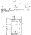
- FIGURE 3 is a schematic electronic circuit diagram of a display system according to the invention which generates the display sequences shown in Figures 1 to 2;
- FIGURE 4 is a schematic block diagram showing further wiring detail of the system shown in Figure 3;
- FIGURE 5 shows an example of the accelerometer connections as part of the electronic circuit used to control a display system according to the invention;
- FIGURE 6 shows further wiring details of the bar graph driver part of the circuit shown in Figure 3;
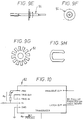
- FIGURE 7 shows a sectional side elevation of the speed sensor and opto-switch part of the display system according to the invention;
- FIGURE 8 gives electrical details of the opto-switch shown in Figure 7 and connected to the circuitry shown in Figures 3 and 4;
- FIGURE 9 parts A to H show various elevation drawings of mechanical components of the opto-switch shown in Figure 7;
- FIGURE 10 shows details of the electrical connectors part of the proximity sensor shown in Figures 3 and 4;
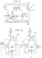
- FIGURE 11 shows a pulse time sequence for various component parts of the proximity sensor shown in Figures 3, 4, 11 and 12;
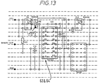
- FIGURE 12 shows wiring to two monostable devices part of the proximity sensor device shown as part of Figures 3 and 4;
- FIGURE 13 shows the wiring of the monostable logic board as partly shown in Figure 12;
-
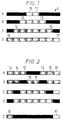
- In a preferred embodiment a motor
vehicle display system 1 according to the invention comprises anarray 2 of eightlights 10 to 17 which normally would be displayed as red lights in a horizontal array. Figures 1A to D show a progressive increase in the number of lights which are illuminated dependent upon the magnitude of deceleration of the vehicle. The lights are represented as 'on' in the drawings by light shading, compared to 'off' which is indicated by a black rectangle. Figure 1A showscentral lights lights 10 to 17 illuminated. - The display may comprise a different number of lamps, for example,
lights - The array of
lights 2 can be carried at the rear of a vehicle such as in the standard high level brake light position in the rear window of a motor car, for example. The lights face rearwardly and are located so that they are readily visible to an observer, e.g. the driver of a motor vehicle travelling or positioned behind the motor vehicle in which the lighting display is mounted. Thelights 10 to 17 are lit in pairs from thecentre pair outer pair lights lights lights vehicle display system 1 and causes further lights to be actuated. Thuslights lights 10 to 13 to indicate relatively large deceleration of the vehicle as shown in Figure 1C. In order to show a more rapid reduction in vehicle velocity all eight lights are illuminated includingouter pair - Other ways of indicating progressive deceleration might be to vary the relative sizes of pairs of lights, for example, increasing the size of
lights inner pair outer pair inner pair outer pair outer pair outer pair inner pair - The lights themselves might comprise electroluminescent bulbs which radiate light through translucent, coloured filters. Alternatively, reflective lights might be used having phosphorescent targets: this can reduce the effect of dazzle of the display. Other forms of light source are envisaged such as light emitting diodes, for example. The display may also comprise a control which enables the intensity of the overall display to be varied, for example, enabling adjustment from a bright day setting to a night setting.
- The operation of the light sequence indicative of deceleration can be independent of the braking system of the vehicle and dependent principally on the absolute vehicle deceleration, except that it is possible to illuminate
lights - An advantage of a display system according to the present invention is that it can be mounted in a vehicle during manufacture, or alternatively, at a later time by making minor modifications to a vehicle, so that a retrofit unit or kit could be made available for the 'after sales' market. This is possible since deceleration can be detected by an accelerometer (described later) which is independent of any existing vehicle components.
- The display system can be used to generate a display indicative of a vehicle having come to rest. This particular arrangement is termed a vehicle stationary indicator (VSI). The display may be animate or static. An animate visual display sequence is shown schematically in Figure 2A to D, by way of example. In this case, six of the eight lights in
array 2 are lit at all times and pairs of lights are deactivated sequentially. Thus, in figure 2A lights 10 and 11 are deactivated whilstlights 12 to 17 are illuminated, and in Figure 2B lights 12 and 13 are deactivated whilst the rest of the display is illuminated. Figures 2C and D show lights 14 and 15 deactivated and 16 and 17 deactivated respectively whilst the rest are lit. This sequence can be operated cyclically whilst the vehicle is stationary, for example, having a repeat period of about 1 second. The dynamic animate effect is useful in catching the attention of drivers in following vehicles. The effect of the animate display is such that it is intended to indicate that the associated vehicle is stationary and not just braking, this fact should be apparent from the display and/or sequence and consequently a number of different sequences could be used. - The animate sequence of the vehicle stationary indicator can be disabled when a following vehicle is less than a certain distance behind the vehicle carrying the
display system 1. This has the beneficial effect of avoiding annoyance or mesmerisation of occupants of following vehicles, for example, when in heavy traffic or when stopped at traffic control lights. An indication that the vehicle is stationary can still be effected by maintaining the outer pair oflights lights 10 to 17 can be reduced when a following vehicle is a predetermined distance behind. This has the advantage of maintaining the same display whilst the vehicle is stationary, thereby avoiding any confusion of the driver of a following vehicle. Thelights 10 to 17 may be dimmed simply by dividing the voltage across the lamps when a proximity sensor, described later, gives a signal indicative of a nearby trailing vehicle. It is apparent that the 'vehicle stationary indicator' display should be terminated when the vehicle starts to move off thus it is appropriate for thedisplay system 1 to comprise a vehicle motion detector (described in detail later) which operates to detect whether the vehicle is moving. - In another embodiment the animate display may change to an even intensity, static display when a trailing vehicle is detected by the proximity sensor. The static display might be a linear array of amber triangular lights for example. In a further form the display only provides a static VSI signal and comprises lights of a preset intensity which is sufficiently low not to dazzle drivers in trailing vehicles. In this latter form a proximity sensor may be omitted thereby reducing the cost of the overall display system. In another form the VSI signal might be generated by the same lights used for the PBW signal where in this latter case the lights are red rectangles, for example and in the former case the lights change to amber triangles, for example, when the vehicle stops.
- Electronic circuitry used to control the light display is shown in Figures 3 and 4. The circuit diagram is schematic but can be seen to generate a logic sequence dependent on various inputs, which actuates the light display shown in Figures 1 and 2.
- The
vehicle display system 1 shown comprises thearray 2 of eightlights 10 to 17 which are 12V 5W (or 21W) lamps for example. The traditional red brake light is generated in the usual way by using a translucent red filter. Pairs oflights power transistors relevant transistor 20 to 23 to illuminate or deactivate each pair of lamps. - The combined display effect of progressive brake warning and vehicle stationary indication are generated in this example using the circuitry shown to open and
close transistors 20 to 23 between the lamps and earth. The circuit comprises a +12V DC power supply (not shown) and a regulator circuit 3C which generates a + 5V output.Accelerometer unit variable resistor 52 and which signal is independent of the mechanical braking system operated by the brake pedal and therefore allows for factors such as skid.Accelerator unit DC converter 70. Theconverter 70 can be a miniature encapsulated 750mW device which provides a + and -12V supply to signalamplifier 71. Theconverter 70 is fully reverse polarity protected and each of the input and output rails are decoupled using electrolytic capacitors (not shown).Amplifier 71 comprises a wheatstone bridge 72 (such as that described in Radio Spares data sheet 8155 issued November 1987 for example). Theamplifier 71 may be an off the shelf item or modified such that in a specific form theamplifier 71 has a gain of 250 and zero adjust from ± 6.7V output. The gain and zero adjustment are set to values compatible with the accelerometer. Theaccelerometer 32 may be an Entran EGD-240-10 for example. Thestrain gauge amplifier 71 is used to raise the signal level from 10mV g to a level compatible withbar graph driver 36 which might be 2.5V g in this specific example. This device as a whole has the advantages of giving a steady state (DC) response, miniature size, robustness, low cost and ease of application. - The analogue output from the accelerometer passes through a 10kOhm variable resistor to a
bar graph driver 36 which is a LM3914 device for example as shown in Figure 6. Variation of the gain and offset of the output signal fromamplifier 33 together with variation ofpotentiometer 52 can be used to alter the input voltage ofdriver 36 for any given vehicle deceleration. In this example thedriver 36 has a linear output to input signal relationship. Thus the number of lights illuminated by the progressive brake warning system may be selected in four levels representative of vehicle deceleration of 0.05g to 0.2g, 0.2g to 0.4g, 0.4g to 0.6g, and 0.6g and above for example. - These ranges are given by way of example and can be varied to suit the type of display used. The lowest threshold level which causes the first deceleration light to come on is preferably set to a level such that simply changing gear does not cause the light to come on but preferably should enable a signal to be generated when the driver is deliberately decelerating, albeit gently, by reducing pressure on the accelerator pedal for example. Also, the incrementation of the levels need not be even, as is approximately the case in the above example, and might vary non-linearly such as exponentially.
-
Power transistors lamps 10 to 17 on by generating a high output from the relevant ORgates 40 to 43. The input totransistor 20, which controlscentral lamps OR gate 40. The default input to ORgate 40 is low since the + 5V supply passes through a resistor andinvertor 44. - The output from
invertor 44 is high whendriver 36 enables pin P1 to take the input toinvertor 44 low. Similarlydriver 36 causes a high output frominvertors accelerometer 32,driver 36 causes only P1 to generate a low input atinvertor 44. A high input signal atOR gate 40 causes a high input at the input base oftransistor 20 which thereby illuminateslights - Figures 3 and 4 also show how, using
device 80, a brake pedal signal can be used to illuminate central pair oflights - The vehicle stationary indication display described with reference to Figure 2 can be effected using opto-
switch 34 and circuitry shown in Figures 3, 4 and 8 which make up a vehicle motion detector which measures the vehicles velocity, although for the vehicle stationary indication display it is only essential to know whether the vehicle is stationary or moving. - The information that the vehicle is stationary can be obtained using a slotted opto-
sensor 34 attached to the rear of a vehicle speedometer (not shown). The speedometer drive cable spins a slotteddisk 91 housed in anylon casing 95. The slotteddisk 91 is attached to aspindle 94 which is placed serially between the speedometer and cable. The opto-switch 34 comprisesLED 92 and photo-diode 93. As the spindle turns, infra-red light fromLED 92 is alternately obscured then allowed to fall on photo-diode 93. Integrated circuitry filters the output from photo-diode 93 to produce a clean TTL (Transistor/Transistor Logic) compatible square wave, the frequency of which is proportional to vehicle speed. - The signal output from opto-
switch 34 is applied to the RC (resistor/capacitor)network 100 shown in Figure 3. When the signal is high (+ 12V) the small 0.1 microfarad capacitor quickly charges through the first 10 kilo-Ohm resistor. As the signal voltage falls back to zero the current stored in the small capacitor discharges through the route of least resistance, in this case through the diode and into the relatively large 100 microF capacitator. Without a potential applied across the capacitator however the charge leaks away through the 10 kilo-Ohm resistor as it cannot pass back through the diode. Provided that the frequency of the square wave is low enough the charge in the 100 microF capacitator leaks away almost completely before being charged once more. The voltage seen by the positive terminal on the comparator 25 (such as the 339 device for example) will be virtually zero with small peaks of around 12mV as each packet of charge is pumped through. As the frequency increases the small capacitor pumps more small amounts of charge into the large capacitor, raising the potential across it and thus the voltage at the terminal of the comparator 25. This time the frequency is such that the charge has not enough time to leak completely away through the second resistor so that the charge in the large capacitor increases with each amount of charge delivered to it. After a number of cycles the system will reach an equilibrium and a steady voltage will be present at the positive terminal of the comparator, the voltage increasing in some proportion with the vehicle speed. - The comparator 25 has a reference voltage adjusted by the voltage divider 53 applied to its negative input. When the positive terminal is below the reference voltage the output of the comparator 25 is kept high by the 5V pull up. Above the reference voltage the comparator 25 pulls its output to ground. The components in the
RC network 100 and the voltage reference are adjusted so that the transition occurs at very low vehicle speed close to stationary. Thus a binary signal is available to the control system indicating 'vehicle stationary' (logic 1) or 'vehicle not stationary' (logic 0). - The mechanical components of the opto-switch device are shown in Figures 9 A to H. Where Figure 9A shows an end elevation from the cable side and Figure 9B is a sectional side elevation along axis A-A of
housing part 95A. Figure 9C shows an end elevation from the speedometer end and Figure 9D is a sectional side elevation on axis B-B ofhousing part 95B. Figure 9E shows a side elevation ofspindle 94 whilst Figure 9F is an end elevation thereof. Figure 9G is an end elevation of slotteddisk 91 and Figure 9H a view of a clip used to complete the assembly. - The opto-switch device is given by way of example only and it is envisaged that the vehicle stationary indication display may be enabled using input data for any form of stationary detection such as from an electronic speedometer or from an anti-lock braking system (ABS). With regard to the latter it is possible to modify the present, commonly used ABS components to provide the information required by the display system in both its PBW and VSI roles. Anti-lock braking systems typically comprise a device connected to a wheel hub which device rotates with the wheel to provide an electronic signal proportional to the rate of revolution of the wheel, for example by using an electromagnetic inductive technique. For ABS purposes it is only required to know if the wheel locks. However, for the purposes of the present display system, greater information about the vehicle's speed is required in order for deceleration to be calculated. Therefore, modification of the ABS inductive device can be carried out to provide appropriate information, discussed later, in the device output signal.
- In the VSI system described here, a square wave generator 37 triggers a counter 38 which is a 74161 device for example. Using AND gates 24a and 24b, only when the outputs from comparator 25 and oscillator 37 are high and proximity sensor 60 (described later) is low, is the clock input to counter 38 high. Whilst the vehicle is stationary the count rate is determined by oscillator 37 which can be configured to generate a specific time interval between the change of display signals shown in Figures 2A to D.
- Counter 38 generates a binary output from 0 to 4 which is fed to multiplexor 39, which is a 74138 device for example. The multiplexor generates high and low outputs at pins M1, M2, M3 and M4 dependent on the input signal from counter 38. Pin M1, M2, M3 and M4 are connected to one input terminal of AND
gates gates 48 to 51 is taken from the output of comparator 25 andproximity sensor 60 at gate 24a which is thus the output signal which enables the animate vehicle stationary indication display. - Outputs from AND
gates 48 to 51 are connected to an input of ORgates 40 to 43 previously described in respect of the progressive brake warning displays. When the vehicle is stopped the input to ORgates 40 to 43 frominvertors 44 to 47 will be low since there is no change in speed to generate a signal output fromaccelerometer 32. Thus when any of the inputs to ORgates 40 to 43 from ANDgates 48 to 51 go high the relevant pair of lamps will be illuminated. The animated cyclic display described with reference to Figure 2 is effected by the timing of oscillator 37 and the switching sequence generated by multiplexor 39. The display sequence can easily be varied by altering these components or, indeed, configuring the electrical circuit differently, for example by wiring individual lamps and not pairs of lamps. - The termination of the animate vehicle stationary display can be achieved in various ways such as by using
proximity sensor 60 shown in Figures 3, 4, 10, 11 and 12 for example. A variety of devices could be used such as infra-red, optical, microwave or radar systems, however an ultrasonic device is described here since, inter alia, it is found easy to weather-proof and has small dimensions and low cost. Theultrasonic transducer 61 can be a small (for example 25mm) 26kHz transducer with a maximum range of 9m when used with a small directional horn, for example. Theproximity sensor 60 includes a remote rangingmodule 62 which drives thetransducer 61 and filters the output from it.Module 62 provides a digital latch output labelled C in Figure 11. As the transducer is triggered the latch is switched low. It stays low until the first echo is received whereby it switches high. It remains high until triggered low again by the start of the next trigger pulse (A in Figure 11). If the object is out of range of the sensor 60 (greater than 9m in this example) then the latch is not switched high by the returning echo. In which case the trigger switches the latch high momentarily then back low, the pulse width being similar to that of the trigger at approximately 180 microseconds say, as shown in Figure 11. The duration of the low pulse from the latch provides a means to calculate the distance of an object, in this case a trailing vehicle. - The digital latch signal is used to set a
monostable device 63, such as a 74123 dual resettable for example, running high. The latch output is tied to + 5V as a logic high state and when it is switched hard on by themodule 62 the latch output is pulled to ground, logic low; otherwise the output is logic high. Thus the latch output it compatible with 5V TTL logic in thecontrol box 3. The total output is applied to the 'A' input of first monostable 63 as shown in Figure 12. Each time the transducer is triggered the falling edge of the latch sets the monostable high as shown in trace D of Figure 11. The monostable timing circuit is calibrated such that it resets the monostable 63 after a period of 0.018s which corresponds to a range of approximately 3m from the transducer. That is a total of 6m travelled by sound at 330m/s. The period of the pulse repetition rate PRR is set at 0.06s (i.e. greater than the time equivalent of the length of sound travel path) in this example.Monostable 63 may be a DM74LS123 device for example where delay Tw = 0.37 CxRx such that for C1 = 10 microfarads and R1 = 10 kilo-Ohm variable and R2= 2.2 kilo-Ohm as shown in Figure 12, Tw= 0.008 to 0.0452s giving a range of 1.34 to 7.45 metres. Selection of delay Tw = 0.018s is therefore only given as an example for vehicle detection up to approximately 3 metres fromtransducer 61. - The digital latch output from
module 62 and the output from monostable 63 are coupled using a logic AND gate. The output of this gate thus gives a logic high state if a car is detected within the specified range, three meters in this example, as shown in trace E of Figure 11. This pulse signal is fed to the 'B' input of a secondmonostable device 64, again a 74123 device for example. The delay period ofdevice 64 is set to correspond to approximately 110% of the period of PRR. - Thus, as long as a car is within range (3m in this example) the output of the second monostable 64 remains high. If the following vehicle moves out of range then monostable 64 is not reactivated and falls back low after 0.066s (110% PRR period) and remains low until a vehicle is again detected in range. Thus, a binary signal is output from
proximity sensor 60 indicating vehicles less than 3m behind (logic high) or, vehicle or vehicles greater than 3m behind (logic low). This is shown as trace F in Figure 11. - The output from
proximity sensor 60 is inverted and fed to AND gate 24a which also has as input the output from comparator 25. If the vehicle is stopped and there is no vehicle within the range ofsensor 60 then both inputs to gate 24a will be high and the animate display is enabled as previously described. - The output from
proximity sensor 60 is also fed to AND gate 24C to which is also applied the output from comparator 25. If the vehicle is stationary and there is a vehicle within the set range then both inputs to AND gate 24C will be high and outer pair oflights display system 1 starts to move in which case the vehicle stationary indicators deactivated entirely - It is also envisaged that whilst an
accelerometer 32 and opto-switch 34 are used in this example it is possible to make use of a vehicle's anti-lock brake system (ABS) and the wheel speed sensors therein in a display system according to the invention. It is possible to continuously measure the speed of a vehicle from this source (or indeed any independent vehicle velocity measuring device) and thereby calculate acceleration using a time reference. It would then be possible to use this source to drive the logic circuit just described to illuminate and deactivatelamps 10 to 17 in accordance with the sequence described with respect to Figures 1 and 2. This technique has the benefit that it substantially uses a system already fitted to generate relevant vehicle data independent of the actual braking system itself. It may therefore be readily incorporated during manufacture and has the advantage of reducing the cost of the display system itself. However, as previously described some modification of currently available ABS devices may be required in order specifically to enhance the signal generated using such a device. In particular it may be necessary to increase the sampling rate of the ABS device in order to provide a signal of sufficient variability to enable preset ranges of deceleration/acceleration to be distinguished. In a preferred form the present display system would derive input data from ABS devices attached to diagonally opposite wheels on a vehicle. Additionally, the ABS device and a time reference system as just described could be used to provide a signal to a display which is indicative of the vehicle travelling at constant speed or accelerating. The display for the latter might comprise an array of green lights for example the number of which that are activated depending on the magnitude of acceleration. - It is also envisaged that a display indicator for presenting a PBW or VSI signal to a driver may be fitted in vehicles to be visible to the driver of that vehicle, where the display indicator is responsive to a vehicle motion detection means or a vehicle deceleration detection means in another vehicle. Thus a display indicator in a trailing vehicle might receive a radio signal from a leading vehicle which radio signal contains information about the state of motion of the leading vehicle.
- The display indicator would therefore comprise a radio receiver and means either to distinguish the signal from the immediately leading vehicle when presented with several signals from several leading vehicles or to terminate the display in order not to present erroneous information to a driver in such circumstances of several signals being received by the radio receiver.
Claims (21)
- A motor vehicle display system comprising vehicle motion detection means and an indicator, said vehicle motion detection means being operatively communicating with said indicator to generate a predetermined signal so that said indicator presents a visual display indicative of the motor vehicle being stationary.
- A motor vehicle display system comprising vehicle deceleration detection means and an indicator, said deceleration detection means being operatively communicating with said indicator to generate a predetermined signal independently of the braking system of the vehicle so that said indicator presents a visual display indicative of the magnitude of deceleration of the vehicle.
- A motor vehicle display system according to both claims 1 and 2.
- A motor vehicle display system according to any of claims 1, 2 or 3 wherein the motion detection means and/or deceleration detection means are mountable in a first vehicle and the indicator(s) is mountable in a second vehicle, said detection means comprising transmitter means for communicating with the indicator which comprises a receiver means.
- A motor vehicle display system as claimed in claims 2, 3 or claim 4 when dependent on claim 2 or 3, wherein said indicator is responsive to a finite number of discrete signals from said vehicle deceleration detection means each discrete signal indicative of a different range of values of vehicle deceleration.
- A motor vehicle display as claimed in claim 5 wherein said indicator comprises an array of lamps wherein the number of lamps illuminated is indicative of a range of magnitudes of deceleration of the motor vehicle.
- A motor vehicle display system as claimed in claim 6 wherein said finite number of discrete ranges of magnitudes of deceleration is four and said array of lamps comprises a row of seven lamps wherein a first single lamp and then pairs of lamps are illuminated respectively for the first and then subsequent ranges of deceleration.
- A motor vehicle display system as claimed in any preceding claim wherein said vehicle deceleration detection means or said vehicle motion detection means comprises a vehicle velocity measuring means operative to measure the velocity of a vehicle and thereby determine whether a vehicle is moving or stationary.
- A motor vehicle display system as claimed in claim 8 wherein said vehicle deceleration detection means comprises a vehicle velocity measuring means and a timing device which together are operative to provide an output signal from said vehicle deceleration detection means which is indicative of the magnitude of vehicle deceleration.
- A motor vehicle display system as claimed in claims 8 or 9 wherein said vehicle velocity measuring means comprises components of an anti-lock braking system for the vehicle.
- A motor vehicle display system as claimed in any preceding claim wherein said predetermined indicator signal which is indicative of the vehicle being stationary is a time dependent visual signal.
- A vehicle display system as claimed in any preceding claim which further comprises a vehicle distance measuring device which is operative to detect the presence of a following vehicle within a preset distance behind a vehicle having said motor vehicle display system.
- A motor vehicle display system as claimed in claim 11 or 12 wherein a time independent visual signal is produced after said time dependent visual signal is deactivated.
- A motor vehicle display system as claimed in any preceding claim wherein said vehicle stationary indicator comprises an array of amber or red triangular lights.
- A motor vehicle display system according to any preceding claim comprising means for determining the velocity, deceleration and acceleration of a vehicle, said means being operative to provide a signal to an indicator which signal is indicative of the state of motion of the vehicle and said indicator being operative to produce a predetermined visual display.
- A motor vehicle comprising a vehicle display system according to any of the preceding claims.
- A vehicle proximity measuring device comprising a transducer and a control module wherein said transducer is operative to produce an output signal and to receive an input signal, the time delay between the output and input signals being indicative of the distance between the transducer and an object, and wherein said control module is operative to drive said transducer and to provide a module output signal dependent upon the time delay between transducer output and input signals.
- A vehicle proximity measuring device as claimed in claim 17 wherein said module output signal is a binary signal wherein one logic state is indicative of the presence of an object within a predetermined distance of the transducer and the other logic state is indicative of no object being within the predetermined distance.
- A vehicle proximity measuring device as claimed in claim 18 wherein said control module comprises two monostable devices being operatively interconnected to produce a binary output signal indicative of the presence or absence of an object within said predetermined distance of the transducer.
- A vehicle proximity measuring device as claimed in claims 17, 18 or 19 which is fitted to a first vehicle and which is operative to measure the distance between the first vehicle and a second vehicle positioned rearwardly of the first vehicle.
- Use of a vehicle proximity detector as claimed in claims 17 to 20 to cause a change in display by a vehicle display system as claimed in any one of claims 1 to 16.
Applications Claiming Priority (3)
| Application Number | Priority Date | Filing Date | Title |
|---|---|---|---|
| GB9202472 | 1992-02-05 | ||
| GB929202472A GB9202472D0 (en) | 1992-02-05 | 1992-02-05 | Motor vehicle display system and ranging device |
| EP93904172A EP0680418B1 (en) | 1992-02-05 | 1993-02-05 | Motor vehicle display system for indicating the state of motion of the subject vehicle and method of indicating such state |
Related Parent Applications (1)
| Application Number | Title | Priority Date | Filing Date |
|---|---|---|---|
| EP93904172A Division EP0680418B1 (en) | 1992-02-05 | 1993-02-05 | Motor vehicle display system for indicating the state of motion of the subject vehicle and method of indicating such state |
Publications (2)
| Publication Number | Publication Date |
|---|---|
| EP0939002A2 true EP0939002A2 (en) | 1999-09-01 |
| EP0939002A3 EP0939002A3 (en) | 1999-10-13 |
Family
ID=10709896
Family Applications (2)
| Application Number | Title | Priority Date | Filing Date |
|---|---|---|---|
| EP93904172A Expired - Lifetime EP0680418B1 (en) | 1992-02-05 | 1993-02-05 | Motor vehicle display system for indicating the state of motion of the subject vehicle and method of indicating such state |
| EP99108812A Withdrawn EP0939002A3 (en) | 1992-02-05 | 1993-02-05 | Motor vehicle display system and ranging device |
Family Applications Before (1)
| Application Number | Title | Priority Date | Filing Date |
|---|---|---|---|
| EP93904172A Expired - Lifetime EP0680418B1 (en) | 1992-02-05 | 1993-02-05 | Motor vehicle display system for indicating the state of motion of the subject vehicle and method of indicating such state |
Country Status (12)
| Country | Link |
|---|---|
| US (2) | US5828319A (en) |
| EP (2) | EP0680418B1 (en) |
| JP (1) | JPH09503176A (en) |
| KR (1) | KR100328324B1 (en) |
| AT (1) | ATE188175T1 (en) |
| AU (1) | AU3505893A (en) |
| CA (1) | CA2129234C (en) |
| DE (1) | DE69327472T2 (en) |
| ES (1) | ES2144457T3 (en) |
| GB (1) | GB9202472D0 (en) |
| PT (1) | PT680418E (en) |
| WO (1) | WO1993015931A2 (en) |
Cited By (2)
| Publication number | Priority date | Publication date | Assignee | Title |
|---|---|---|---|---|
| GB2351858A (en) * | 1999-07-07 | 2001-01-10 | Robert Keith Jordan | Vehicle deceleration indicator |
| GB2434262A (en) * | 2006-01-17 | 2007-07-18 | Peter Fabian Mark Kittoe | A brake light system for a vehicle in which a display is generated which is indicative of the magnitude of the vehicle deceleration |
Families Citing this family (61)
| Publication number | Priority date | Publication date | Assignee | Title |
|---|---|---|---|---|
| GB2291244B (en) * | 1994-07-15 | 1998-02-11 | Design Technology & Innovation | Vehicle safety systems |
| US6133852A (en) * | 1994-08-05 | 2000-10-17 | Design Technology | Motor vehicle system and ranging device |
| GB2301954A (en) * | 1995-06-05 | 1996-12-18 | Terence Watts | Vehicle deceleration indicator system |
| GB2306811A (en) * | 1995-11-02 | 1997-05-07 | Kenneth Blakeley | Vehicle deceleration warning lamp system |
| GB2319124B (en) * | 1996-11-07 | 2001-04-11 | Design Technology & Innovation | Motor vehicle display system and ranging device |
| DE19712457A1 (en) * | 1997-03-25 | 1998-10-01 | Bosch Gmbh Robert | System for generating a brake signal in a motor vehicle |
| GB2329704B (en) | 1997-09-26 | 2002-02-13 | Design Technology & Innovation | An improved motor vehicle display apparatus |
| US6268792B1 (en) * | 1998-05-14 | 2001-07-31 | John D. Newton | Progressive brake light gauge |
| US6081188A (en) | 1998-06-08 | 2000-06-27 | Emergency Warning Systems, Inc. | Vehicular hazard warning system |
| GB9816376D0 (en) * | 1998-07-29 | 1998-09-23 | Ball Racing Developments Limit | Indicating means |
| FR2787400B1 (en) * | 1998-12-21 | 2001-01-26 | Valeo Vision | INSTALLATION FOR SIGNALING THE DECELERATION OF A MOTOR VEHICLE COMPRISING A LIGHT EMITTING A LIGHT FLOW OF CONSTANT INTENSITY |
| BR9917100A (en) * | 1999-02-11 | 2001-11-06 | Intellibrake Proprietary Ltd | Progressive braking system |
| GB2347027A (en) * | 1999-02-17 | 2000-08-23 | George Aitchieson Nor Longmuir | Vehicle braking warning indicator |
| US6150933A (en) * | 1999-04-07 | 2000-11-21 | Matsumoto; Kiyoto | Vehicle brake light system |
| US6411204B1 (en) * | 1999-11-15 | 2002-06-25 | Donnelly Corporation | Deceleration based anti-collision safety light control for vehicle |
| WO2001042045A1 (en) * | 1999-12-11 | 2001-06-14 | Youngking Pty. Ltd. | Deceleration warning system |
| US6351211B1 (en) * | 2000-01-25 | 2002-02-26 | M&P Ventures, Inc. | Brake warning method and system |
| US6333688B1 (en) * | 2000-03-17 | 2001-12-25 | Tyrone A. Brown | Tail light enhancement system |
| IL138838A0 (en) * | 2000-10-03 | 2001-10-31 | Menachem Hadar | Vehicle brake light system and method |
| US6753769B1 (en) * | 2001-03-29 | 2004-06-22 | Lawrence T. Elliott | Progressive slow-stop signaling system |
| GB2382404A (en) * | 2001-11-22 | 2003-05-28 | Aco Esapov | Lights displaying braking intensity |
| US6870474B1 (en) * | 2002-11-25 | 2005-03-22 | Budd Brothers | Vehicle safety signaling system |
| US7075423B2 (en) * | 2003-10-06 | 2006-07-11 | Joseph Edward Currie | Combination illuminating inverse function power indicator and a brake light |
| DE10355023A1 (en) * | 2003-11-25 | 2004-12-23 | Daimlerchrysler Ag | Covering of a surface with optically active, e.g. electroluminescent film, surface segments, said segments being controllable in a temporal and spatial manner to create desired optical effects |
| US7057501B1 (en) | 2004-04-23 | 2006-06-06 | Darryl Davis | Tailgate warning and reporting system |
| US7155329B2 (en) * | 2004-05-24 | 2006-12-26 | General Motors Of Canada | Vehicle deceleration display system and calculation method |
| ES2251309B1 (en) * | 2004-10-07 | 2007-06-16 | Jose Luis De La Torre Barreiro | BRAKING INDICATOR DEVICE. |
| US7242287B1 (en) | 2004-10-19 | 2007-07-10 | Joseph Giovinazzo | Vehicle warning system and method |
| FR2892988A1 (en) * | 2005-11-10 | 2007-05-11 | Robeert Christian Coron | Motor vehicle indicator system has green, orange and red lights to show whether it is accelerating, slowing or braking |
| AU2006211855B2 (en) * | 2006-09-01 | 2014-02-13 | Mark William Gallon | Braking Display Apparatus |
| US20090261963A1 (en) * | 2008-04-22 | 2009-10-22 | Ault Scott T | Vehicle Deceleration Warning System |
| CN101482243B (en) * | 2008-08-27 | 2010-12-22 | 奇瑞汽车股份有限公司 | High-position braking lamp control system with graded illumination function and its control method |
| US8823506B2 (en) | 2009-05-15 | 2014-09-02 | Jepp Industries, Inc. | System for enhancing perception of a motor vehicle's mark emblem |
| US8188850B2 (en) * | 2009-05-15 | 2012-05-29 | Jepp Industries, Inc. | System for enhancing perception of a motor vehicle's mark emblem |
| US9639688B2 (en) | 2010-05-27 | 2017-05-02 | Ford Global Technologies, Llc | Methods and systems for implementing and enforcing security and resource policies for a vehicle |
| ES2379247B1 (en) | 2010-08-10 | 2012-11-27 | Pere Pi I Parera | SECURITY SYSTEM INDICATOR OF THE DEACELERATION OF A VEHICLE. |
| EP2668066A4 (en) * | 2011-01-26 | 2018-04-04 | Adac Plastics, Inc. | Center high-mount brake light system |
| US9452735B2 (en) | 2011-02-10 | 2016-09-27 | Ford Global Technologies, Llc | System and method for controlling a restricted mode in a vehicle |
| US10145960B2 (en) | 2011-02-24 | 2018-12-04 | Ford Global Technologies, Llc | System and method for cell phone restriction |
| US8522320B2 (en) | 2011-04-01 | 2013-08-27 | Ford Global Technologies, Llc | Methods and systems for authenticating one or more users of a vehicle communications and information system |
| US8938224B2 (en) | 2011-05-12 | 2015-01-20 | Ford Global Technologies, Llc | System and method for automatically enabling a car mode in a personal communication device |
| US8788113B2 (en) | 2011-06-13 | 2014-07-22 | Ford Global Technologies, Llc | Vehicle driver advisory system and method |
| US10097993B2 (en) | 2011-07-25 | 2018-10-09 | Ford Global Technologies, Llc | Method and apparatus for remote authentication |
| US8849519B2 (en) | 2011-08-09 | 2014-09-30 | Ford Global Technologies, Llc | Method and apparatus for vehicle hardware theft prevention |
| BR102012017584B1 (en) * | 2011-12-08 | 2019-03-26 | Agco Do Brasil Máquinas E Equipamentos Agrícolas Ltda. | SPEED CORRECTION AID SYSTEM AND METHOD |
| KR101364487B1 (en) * | 2012-02-03 | 2014-02-20 | (주)에핏라이트 | The apparatus for controlling a break lamp for a car |
| US9569403B2 (en) | 2012-05-03 | 2017-02-14 | Ford Global Technologies, Llc | Methods and systems for authenticating one or more users of a vehicle communications and information system |
| US8866604B2 (en) | 2013-02-14 | 2014-10-21 | Ford Global Technologies, Llc | System and method for a human machine interface |
| US9688246B2 (en) | 2013-02-25 | 2017-06-27 | Ford Global Technologies, Llc | Method and apparatus for in-vehicle alarm activation and response handling |
| US8947221B2 (en) | 2013-02-26 | 2015-02-03 | Ford Global Technologies, Llc | Method and apparatus for tracking device connection and state change |
| US9141583B2 (en) | 2013-03-13 | 2015-09-22 | Ford Global Technologies, Llc | Method and system for supervising information communication based on occupant and vehicle environment |
| US9002536B2 (en) | 2013-03-14 | 2015-04-07 | Ford Global Technologies, Llc | Key fob security copy to a mobile phone |
| RU2570843C2 (en) * | 2013-09-18 | 2015-12-10 | Федеральное государственное унитарное предприятие "Центральный ордена Трудового Красного Знамени научно-исследовательский автомобильный и автомоторный институт "НАМИ" | Method of determining slowing down of rotating bodies |
| US20150266414A1 (en) * | 2014-03-24 | 2015-09-24 | Tophertronics, Llc | Automatic Braking Indicator |
| US10249123B2 (en) | 2015-04-09 | 2019-04-02 | Ford Global Technologies, Llc | Systems and methods for mobile phone key fob management |
| DE102015223171A1 (en) * | 2015-11-24 | 2017-05-24 | Osram Gmbh | Safety device and method for indicating a distance for vehicles and vehicle with the safety device |
| US10246008B2 (en) * | 2016-11-14 | 2019-04-02 | Samuel Dingus | Variable accelerator light assembly |
| US20190071002A1 (en) * | 2017-09-05 | 2019-03-07 | Cary Scott | Dynamic brake light system |
| US11208034B2 (en) | 2018-02-20 | 2021-12-28 | Ford Global Technologies, Llc | Vehicle lamp assembly |
| US20210394616A1 (en) * | 2020-06-23 | 2021-12-23 | Bruce Matthew Paggeot | Method and Apparatus for Real-Time Acceleration Indication |
| DE102020120596A1 (en) | 2020-08-05 | 2022-02-10 | Audi Aktiengesellschaft | Method for operating a rear light of a motor vehicle and motor vehicle |
Citations (9)
| Publication number | Priority date | Publication date | Assignee | Title |
|---|---|---|---|---|
| GB2114826A (en) * | 1982-01-18 | 1983-08-24 | Nan Mu Chiou | Safety indicator system for motor vehicles |
| NL8300073A (en) * | 1983-01-10 | 1984-08-01 | Arjeh Tal | Speed indicators for motor vehicle - are installed on windscreen and rear window as aid to other drivers |
| US4467313A (en) * | 1980-11-14 | 1984-08-21 | Nippon Soken, Inc. | Automotive rear safety checking apparatus |
| JPS60197442A (en) * | 1984-03-20 | 1985-10-05 | Nippon Denso Co Ltd | Rear confirming apparatus for car |
| US4626850A (en) * | 1983-05-16 | 1986-12-02 | David Chey | Vehicle detection and collision avoidance apparatus |
| EP0263262A2 (en) * | 1986-10-08 | 1988-04-13 | Dr.Ing.h.c. F. Porsche Aktiengesellschaft | Distance-regulating system for automotive vehicles |
| DE3907714A1 (en) * | 1989-03-10 | 1990-09-20 | Battelle Institut E V | Arrangement for indicating that a motor vehicle is braking |
| WO1991007672A2 (en) * | 1989-11-09 | 1991-05-30 | Lewis Montague | Remote sensing apparatus for a vehicle |
| DE4020610A1 (en) * | 1990-06-28 | 1992-01-02 | Schreiber Hans | Registering alarm signal for collision protection in motor vehicle - using inertial sensor to activate warning system for following vehicles by flashing rear lights |
Family Cites Families (16)
| Publication number | Priority date | Publication date | Assignee | Title |
|---|---|---|---|---|
| US3846749A (en) * | 1973-02-01 | 1974-11-05 | Massachusetts Inst Technology | Vehicle brake light control system |
| US4258353A (en) * | 1979-12-13 | 1981-03-24 | Carlson Robert W | Vehicle acceleration/deceleration warning system |
| US4566862A (en) * | 1982-02-23 | 1986-01-28 | General Pneumatics Corporation | Fluid apparatus and methods, as for inflating inflatable structures |
| US4556862A (en) * | 1983-05-16 | 1985-12-03 | Meinershagen Charles I | Vehicle direction signal and slow warning system employing moving pattern of simultaneously ON lamps |
| US4600913A (en) * | 1984-12-24 | 1986-07-15 | Caine Harold A | Collision avoidance device |
| US4663609A (en) * | 1985-10-21 | 1987-05-05 | Rosario George M | Brake alert device |
| KR910001149B1 (en) * | 1986-04-23 | 1991-02-25 | 주식회사 금성사 | Analarming device into each other |
| KR910005721B1 (en) * | 1988-08-12 | 1991-08-02 | 현대전자산업 주식회사 | Displaying device and its controlling method for vehicle |
| US4894641A (en) * | 1989-01-24 | 1990-01-16 | Cotron Corporation | Real-time speed display apparatus |
| US5162794A (en) * | 1989-11-21 | 1992-11-10 | Nancy Seith | Safe trailing distance warning for vehicles |
| US5017904A (en) * | 1990-04-16 | 1991-05-21 | General Motors Corporation | Braking indicator system |
| US5164701A (en) * | 1990-04-30 | 1992-11-17 | Nan Mu Chiou | Car-operation-condition indicating apparatus |
| US5089805A (en) * | 1990-05-07 | 1992-02-18 | Salsman Robert K | Brake light system to indicate intensity of slow down |
| US4987405A (en) * | 1990-06-04 | 1991-01-22 | Jakobowski Walter T | Elevated brake light signal module |
| US5150098A (en) * | 1990-11-13 | 1992-09-22 | Robert Rakow | Brake signaling system and process |
| US5148147A (en) * | 1990-12-03 | 1992-09-15 | Kobres Arthur L | Vehicle deceleration measurement system |
-
1992
- 1992-02-05 GB GB929202472A patent/GB9202472D0/en active Pending
-
1993
- 1993-02-05 ES ES93904172T patent/ES2144457T3/en not_active Expired - Lifetime
- 1993-02-05 AT AT93904172T patent/ATE188175T1/en not_active IP Right Cessation
- 1993-02-05 WO PCT/GB1993/000251 patent/WO1993015931A2/en active IP Right Grant
- 1993-02-05 US US08/284,540 patent/US5828319A/en not_active Expired - Fee Related
- 1993-02-05 PT PT93904172T patent/PT680418E/en unknown
- 1993-02-05 EP EP93904172A patent/EP0680418B1/en not_active Expired - Lifetime
- 1993-02-05 CA CA002129234A patent/CA2129234C/en not_active Expired - Fee Related
- 1993-02-05 AU AU35058/93A patent/AU3505893A/en not_active Abandoned
- 1993-02-05 JP JP5513885A patent/JPH09503176A/en active Pending
- 1993-02-05 EP EP99108812A patent/EP0939002A3/en not_active Withdrawn
- 1993-02-05 DE DE69327472T patent/DE69327472T2/en not_active Expired - Fee Related
-
1994
- 1994-08-03 KR KR1019940702663A patent/KR100328324B1/en not_active IP Right Cessation
-
1997
- 1997-02-05 US US08/795,076 patent/US5856793A/en not_active Expired - Fee Related
Patent Citations (9)
| Publication number | Priority date | Publication date | Assignee | Title |
|---|---|---|---|---|
| US4467313A (en) * | 1980-11-14 | 1984-08-21 | Nippon Soken, Inc. | Automotive rear safety checking apparatus |
| GB2114826A (en) * | 1982-01-18 | 1983-08-24 | Nan Mu Chiou | Safety indicator system for motor vehicles |
| NL8300073A (en) * | 1983-01-10 | 1984-08-01 | Arjeh Tal | Speed indicators for motor vehicle - are installed on windscreen and rear window as aid to other drivers |
| US4626850A (en) * | 1983-05-16 | 1986-12-02 | David Chey | Vehicle detection and collision avoidance apparatus |
| JPS60197442A (en) * | 1984-03-20 | 1985-10-05 | Nippon Denso Co Ltd | Rear confirming apparatus for car |
| EP0263262A2 (en) * | 1986-10-08 | 1988-04-13 | Dr.Ing.h.c. F. Porsche Aktiengesellschaft | Distance-regulating system for automotive vehicles |
| DE3907714A1 (en) * | 1989-03-10 | 1990-09-20 | Battelle Institut E V | Arrangement for indicating that a motor vehicle is braking |
| WO1991007672A2 (en) * | 1989-11-09 | 1991-05-30 | Lewis Montague | Remote sensing apparatus for a vehicle |
| DE4020610A1 (en) * | 1990-06-28 | 1992-01-02 | Schreiber Hans | Registering alarm signal for collision protection in motor vehicle - using inertial sensor to activate warning system for following vehicles by flashing rear lights |
Non-Patent Citations (1)
| Title |
|---|
| PATENT ABSTRACTS OF JAPAN vol. 010, no. 047 (M-456), 25 February 1986 (1986-02-25) & JP 60 197442 A (NIPPON DENSO KK), 5 October 1985 (1985-10-05) * |
Cited By (2)
| Publication number | Priority date | Publication date | Assignee | Title |
|---|---|---|---|---|
| GB2351858A (en) * | 1999-07-07 | 2001-01-10 | Robert Keith Jordan | Vehicle deceleration indicator |
| GB2434262A (en) * | 2006-01-17 | 2007-07-18 | Peter Fabian Mark Kittoe | A brake light system for a vehicle in which a display is generated which is indicative of the magnitude of the vehicle deceleration |
Also Published As
| Publication number | Publication date |
|---|---|
| EP0680418A1 (en) | 1995-11-08 |
| CA2129234A1 (en) | 1993-08-19 |
| WO1993015931A2 (en) | 1993-08-19 |
| US5856793A (en) | 1999-01-05 |
| DE69327472D1 (en) | 2000-02-03 |
| PT680418E (en) | 2000-06-30 |
| ATE188175T1 (en) | 2000-01-15 |
| AU3505893A (en) | 1993-09-03 |
| KR100328324B1 (en) | 2002-09-05 |
| WO1993015931A3 (en) | 1993-11-11 |
| EP0939002A3 (en) | 1999-10-13 |
| EP0680418B1 (en) | 1999-12-29 |
| US5828319A (en) | 1998-10-27 |
| ES2144457T3 (en) | 2000-06-16 |
| JPH09503176A (en) | 1997-03-31 |
| CA2129234C (en) | 2008-01-15 |
| GB9202472D0 (en) | 1992-03-18 |
| DE69327472T2 (en) | 2000-08-10 |
Similar Documents
| Publication | Publication Date | Title |
|---|---|---|
| CA2129234C (en) | Motor vehicle display system and ranging device | |
| US5838259A (en) | Motor vehicle display system and ranging device | |
| US6133852A (en) | Motor vehicle system and ranging device | |
| US5548274A (en) | Strobe light for a vehicle tire and wheel | |
| US20020133282A1 (en) | Brake light system using sequential lamp array and input from velocity measuring device | |
| EP1077833B1 (en) | Motor vehicle display system and ranging device | |
| US4070562A (en) | Acceleration/deceleration alarm system | |
| US5659290A (en) | Speed minder | |
| US3708750A (en) | Elapsed time indicator | |
| EP0381767B1 (en) | Display device for car | |
| US3597730A (en) | Vehicle speed indicator system | |
| GB2260209A (en) | Braking distance indicating and warning device | |
| JPH08509442A (en) | Circuit configuration for adjusting and evaluating wheel sensor signals | |
| US7155329B2 (en) | Vehicle deceleration display system and calculation method | |
| JP3391145B2 (en) | Vehicle deceleration display device | |
| GB2319124A (en) | Indicating state of motion of a vehicle; vehicle ranging device | |
| CN1569517A (en) | Vehicle acceleration or deceleration/brake grading display method using sensor and apparatus therefor | |
| US5818332A (en) | Automobile speed indicator | |
| EP3789738A1 (en) | Speedometer display | |
| KR100413255B1 (en) | Odo meter and speedometer use of ABS ECU | |
| JPH03135850A (en) | Wheel lighting device for automobile | |
| TW504474B (en) | Anti-crash alarm system for vehicles | |
| KR100514389B1 (en) | Device for measuring the tire air pressure and speed of car | |
| CN1075989C (en) | Anti-collision signal display device for automobile | |
| JPH01299465A (en) | Vehicle speedometer that is also used as accelerometer |
Legal Events
| Date | Code | Title | Description |
|---|---|---|---|
| PUAI | Public reference made under article 153(3) epc to a published international application that has entered the european phase |
Free format text: ORIGINAL CODE: 0009012 |
|
| PUAL | Search report despatched |
Free format text: ORIGINAL CODE: 0009013 |
|
| 17P | Request for examination filed |
Effective date: 19990504 |
|
| AC | Divisional application: reference to earlier application |
Ref document number: 680418 Country of ref document: EP |
|
| AK | Designated contracting states |
Kind code of ref document: A2 Designated state(s): AT BE DE DK ES FR GB IT NL PT SE |
|
| RIC1 | Information provided on ipc code assigned before grant |
Free format text: 6G 01S 13/93 A, 6G 08G 1/16 B, 6B 60Q 1/44 B, 6G 01P 1/08 B, 6G 01P 3/489 B, 6G 01P 3/486 B |
|
| AK | Designated contracting states |
Kind code of ref document: A3 Designated state(s): AT BE DE DK ES FR GB IT NL PT SE |
|
| STAA | Information on the status of an ep patent application or granted ep patent |
Free format text: STATUS: THE APPLICATION HAS BEEN WITHDRAWN |
|
| 18W | Application withdrawn |
Withdrawal date: 20010330 |