EP0941902A2 - Vehicle dynamic control system - Google Patents
Vehicle dynamic control system Download PDFInfo
- Publication number
- EP0941902A2 EP0941902A2 EP99301902A EP99301902A EP0941902A2 EP 0941902 A2 EP0941902 A2 EP 0941902A2 EP 99301902 A EP99301902 A EP 99301902A EP 99301902 A EP99301902 A EP 99301902A EP 0941902 A2 EP0941902 A2 EP 0941902A2
- Authority
- EP
- European Patent Office
- Prior art keywords
- deceleration
- road
- curve
- calculator
- vehicle
- Prior art date
- Legal status (The legal status is an assumption and is not a legal conclusion. Google has not performed a legal analysis and makes no representation as to the accuracy of the status listed.)
- Granted
Links
Images


Classifications
-
- B—PERFORMING OPERATIONS; TRANSPORTING
- B60—VEHICLES IN GENERAL
- B60Q—ARRANGEMENT OF SIGNALLING OR LIGHTING DEVICES, THE MOUNTING OR SUPPORTING THEREOF OR CIRCUITS THEREFOR, FOR VEHICLES IN GENERAL
- B60Q9/00—Arrangement or adaptation of signal devices not provided for in one of main groups B60Q1/00 - B60Q7/00, e.g. haptic signalling
-
- B—PERFORMING OPERATIONS; TRANSPORTING
- B60—VEHICLES IN GENERAL
- B60T—VEHICLE BRAKE CONTROL SYSTEMS OR PARTS THEREOF; BRAKE CONTROL SYSTEMS OR PARTS THEREOF, IN GENERAL; ARRANGEMENT OF BRAKING ELEMENTS ON VEHICLES IN GENERAL; PORTABLE DEVICES FOR PREVENTING UNWANTED MOVEMENT OF VEHICLES; VEHICLE MODIFICATIONS TO FACILITATE COOLING OF BRAKES
- B60T8/00—Arrangements for adjusting wheel-braking force to meet varying vehicular or ground-surface conditions, e.g. limiting or varying distribution of braking force
- B60T8/17—Using electrical or electronic regulation means to control braking
- B60T8/1755—Brake regulation specially adapted to control the stability of the vehicle, e.g. taking into account yaw rate or transverse acceleration in a curve
-
- B—PERFORMING OPERATIONS; TRANSPORTING
- B60—VEHICLES IN GENERAL
- B60W—CONJOINT CONTROL OF VEHICLE SUB-UNITS OF DIFFERENT TYPE OR DIFFERENT FUNCTION; CONTROL SYSTEMS SPECIALLY ADAPTED FOR HYBRID VEHICLES; ROAD VEHICLE DRIVE CONTROL SYSTEMS FOR PURPOSES NOT RELATED TO THE CONTROL OF A PARTICULAR SUB-UNIT
- B60W10/00—Conjoint control of vehicle sub-units of different type or different function
- B60W10/04—Conjoint control of vehicle sub-units of different type or different function including control of propulsion units
-
- B—PERFORMING OPERATIONS; TRANSPORTING
- B60—VEHICLES IN GENERAL
- B60W—CONJOINT CONTROL OF VEHICLE SUB-UNITS OF DIFFERENT TYPE OR DIFFERENT FUNCTION; CONTROL SYSTEMS SPECIALLY ADAPTED FOR HYBRID VEHICLES; ROAD VEHICLE DRIVE CONTROL SYSTEMS FOR PURPOSES NOT RELATED TO THE CONTROL OF A PARTICULAR SUB-UNIT
- B60W10/00—Conjoint control of vehicle sub-units of different type or different function
- B60W10/10—Conjoint control of vehicle sub-units of different type or different function including control of change-speed gearings
-
- B—PERFORMING OPERATIONS; TRANSPORTING
- B60—VEHICLES IN GENERAL
- B60W—CONJOINT CONTROL OF VEHICLE SUB-UNITS OF DIFFERENT TYPE OR DIFFERENT FUNCTION; CONTROL SYSTEMS SPECIALLY ADAPTED FOR HYBRID VEHICLES; ROAD VEHICLE DRIVE CONTROL SYSTEMS FOR PURPOSES NOT RELATED TO THE CONTROL OF A PARTICULAR SUB-UNIT
- B60W10/00—Conjoint control of vehicle sub-units of different type or different function
- B60W10/18—Conjoint control of vehicle sub-units of different type or different function including control of braking systems
- B60W10/184—Conjoint control of vehicle sub-units of different type or different function including control of braking systems with wheel brakes
-
- B—PERFORMING OPERATIONS; TRANSPORTING
- B60—VEHICLES IN GENERAL
- B60W—CONJOINT CONTROL OF VEHICLE SUB-UNITS OF DIFFERENT TYPE OR DIFFERENT FUNCTION; CONTROL SYSTEMS SPECIALLY ADAPTED FOR HYBRID VEHICLES; ROAD VEHICLE DRIVE CONTROL SYSTEMS FOR PURPOSES NOT RELATED TO THE CONTROL OF A PARTICULAR SUB-UNIT
- B60W40/00—Estimation or calculation of non-directly measurable driving parameters for road vehicle drive control systems not related to the control of a particular sub unit, e.g. by using mathematical models
- B60W40/02—Estimation or calculation of non-directly measurable driving parameters for road vehicle drive control systems not related to the control of a particular sub unit, e.g. by using mathematical models related to ambient conditions
- B60W40/06—Road conditions
- B60W40/072—Curvature of the road
-
- B—PERFORMING OPERATIONS; TRANSPORTING
- B60—VEHICLES IN GENERAL
- B60W—CONJOINT CONTROL OF VEHICLE SUB-UNITS OF DIFFERENT TYPE OR DIFFERENT FUNCTION; CONTROL SYSTEMS SPECIALLY ADAPTED FOR HYBRID VEHICLES; ROAD VEHICLE DRIVE CONTROL SYSTEMS FOR PURPOSES NOT RELATED TO THE CONTROL OF A PARTICULAR SUB-UNIT
- B60W40/00—Estimation or calculation of non-directly measurable driving parameters for road vehicle drive control systems not related to the control of a particular sub unit, e.g. by using mathematical models
- B60W40/02—Estimation or calculation of non-directly measurable driving parameters for road vehicle drive control systems not related to the control of a particular sub unit, e.g. by using mathematical models related to ambient conditions
- B60W40/06—Road conditions
- B60W40/076—Slope angle of the road
-
- B—PERFORMING OPERATIONS; TRANSPORTING
- B60—VEHICLES IN GENERAL
- B60W—CONJOINT CONTROL OF VEHICLE SUB-UNITS OF DIFFERENT TYPE OR DIFFERENT FUNCTION; CONTROL SYSTEMS SPECIALLY ADAPTED FOR HYBRID VEHICLES; ROAD VEHICLE DRIVE CONTROL SYSTEMS FOR PURPOSES NOT RELATED TO THE CONTROL OF A PARTICULAR SUB-UNIT
- B60W50/00—Details of control systems for road vehicle drive control not related to the control of a particular sub-unit, e.g. process diagnostic or vehicle driver interfaces
- B60W50/08—Interaction between the driver and the control system
- B60W50/14—Means for informing the driver, warning the driver or prompting a driver intervention
-
- B—PERFORMING OPERATIONS; TRANSPORTING
- B60—VEHICLES IN GENERAL
- B60T—VEHICLE BRAKE CONTROL SYSTEMS OR PARTS THEREOF; BRAKE CONTROL SYSTEMS OR PARTS THEREOF, IN GENERAL; ARRANGEMENT OF BRAKING ELEMENTS ON VEHICLES IN GENERAL; PORTABLE DEVICES FOR PREVENTING UNWANTED MOVEMENT OF VEHICLES; VEHICLE MODIFICATIONS TO FACILITATE COOLING OF BRAKES
- B60T2260/00—Interaction of vehicle brake system with other systems
- B60T2260/04—Automatic transmission
-
- B—PERFORMING OPERATIONS; TRANSPORTING
- B60—VEHICLES IN GENERAL
- B60W—CONJOINT CONTROL OF VEHICLE SUB-UNITS OF DIFFERENT TYPE OR DIFFERENT FUNCTION; CONTROL SYSTEMS SPECIALLY ADAPTED FOR HYBRID VEHICLES; ROAD VEHICLE DRIVE CONTROL SYSTEMS FOR PURPOSES NOT RELATED TO THE CONTROL OF A PARTICULAR SUB-UNIT
- B60W10/00—Conjoint control of vehicle sub-units of different type or different function
- B60W10/04—Conjoint control of vehicle sub-units of different type or different function including control of propulsion units
- B60W10/06—Conjoint control of vehicle sub-units of different type or different function including control of propulsion units including control of combustion engines
-
- B—PERFORMING OPERATIONS; TRANSPORTING
- B60—VEHICLES IN GENERAL
- B60W—CONJOINT CONTROL OF VEHICLE SUB-UNITS OF DIFFERENT TYPE OR DIFFERENT FUNCTION; CONTROL SYSTEMS SPECIALLY ADAPTED FOR HYBRID VEHICLES; ROAD VEHICLE DRIVE CONTROL SYSTEMS FOR PURPOSES NOT RELATED TO THE CONTROL OF A PARTICULAR SUB-UNIT
- B60W50/00—Details of control systems for road vehicle drive control not related to the control of a particular sub-unit, e.g. process diagnostic or vehicle driver interfaces
- B60W2050/0001—Details of the control system
- B60W2050/0043—Signal treatments, identification of variables or parameters, parameter estimation or state estimation
- B60W2050/005—Sampling
- B60W2050/0051—Sampling combined with averaging
-
- B—PERFORMING OPERATIONS; TRANSPORTING
- B60—VEHICLES IN GENERAL
- B60W—CONJOINT CONTROL OF VEHICLE SUB-UNITS OF DIFFERENT TYPE OR DIFFERENT FUNCTION; CONTROL SYSTEMS SPECIALLY ADAPTED FOR HYBRID VEHICLES; ROAD VEHICLE DRIVE CONTROL SYSTEMS FOR PURPOSES NOT RELATED TO THE CONTROL OF A PARTICULAR SUB-UNIT
- B60W50/00—Details of control systems for road vehicle drive control not related to the control of a particular sub-unit, e.g. process diagnostic or vehicle driver interfaces
- B60W2050/0062—Adapting control system settings
- B60W2050/007—Switching between manual and automatic parameter input, and vice versa
- B60W2050/0071—Controller overrides driver automatically
-
- B—PERFORMING OPERATIONS; TRANSPORTING
- B60—VEHICLES IN GENERAL
- B60W—CONJOINT CONTROL OF VEHICLE SUB-UNITS OF DIFFERENT TYPE OR DIFFERENT FUNCTION; CONTROL SYSTEMS SPECIALLY ADAPTED FOR HYBRID VEHICLES; ROAD VEHICLE DRIVE CONTROL SYSTEMS FOR PURPOSES NOT RELATED TO THE CONTROL OF A PARTICULAR SUB-UNIT
- B60W2510/00—Input parameters relating to a particular sub-units
- B60W2510/18—Braking system
- B60W2510/182—Brake pressure, e.g. of fluid or between pad and disc
-
- B—PERFORMING OPERATIONS; TRANSPORTING
- B60—VEHICLES IN GENERAL
- B60W—CONJOINT CONTROL OF VEHICLE SUB-UNITS OF DIFFERENT TYPE OR DIFFERENT FUNCTION; CONTROL SYSTEMS SPECIALLY ADAPTED FOR HYBRID VEHICLES; ROAD VEHICLE DRIVE CONTROL SYSTEMS FOR PURPOSES NOT RELATED TO THE CONTROL OF A PARTICULAR SUB-UNIT
- B60W2520/00—Input parameters relating to overall vehicle dynamics
- B60W2520/10—Longitudinal speed
- B60W2520/105—Longitudinal acceleration
-
- B—PERFORMING OPERATIONS; TRANSPORTING
- B60—VEHICLES IN GENERAL
- B60W—CONJOINT CONTROL OF VEHICLE SUB-UNITS OF DIFFERENT TYPE OR DIFFERENT FUNCTION; CONTROL SYSTEMS SPECIALLY ADAPTED FOR HYBRID VEHICLES; ROAD VEHICLE DRIVE CONTROL SYSTEMS FOR PURPOSES NOT RELATED TO THE CONTROL OF A PARTICULAR SUB-UNIT
- B60W2520/00—Input parameters relating to overall vehicle dynamics
- B60W2520/12—Lateral speed
- B60W2520/125—Lateral acceleration
-
- B—PERFORMING OPERATIONS; TRANSPORTING
- B60—VEHICLES IN GENERAL
- B60W—CONJOINT CONTROL OF VEHICLE SUB-UNITS OF DIFFERENT TYPE OR DIFFERENT FUNCTION; CONTROL SYSTEMS SPECIALLY ADAPTED FOR HYBRID VEHICLES; ROAD VEHICLE DRIVE CONTROL SYSTEMS FOR PURPOSES NOT RELATED TO THE CONTROL OF A PARTICULAR SUB-UNIT
- B60W2556/00—Input parameters relating to data
- B60W2556/45—External transmission of data to or from the vehicle
- B60W2556/50—External transmission of data to or from the vehicle for navigation systems
-
- B—PERFORMING OPERATIONS; TRANSPORTING
- B60—VEHICLES IN GENERAL
- B60W—CONJOINT CONTROL OF VEHICLE SUB-UNITS OF DIFFERENT TYPE OR DIFFERENT FUNCTION; CONTROL SYSTEMS SPECIALLY ADAPTED FOR HYBRID VEHICLES; ROAD VEHICLE DRIVE CONTROL SYSTEMS FOR PURPOSES NOT RELATED TO THE CONTROL OF A PARTICULAR SUB-UNIT
- B60W30/00—Purposes of road vehicle drive control systems not related to the control of a particular sub-unit, e.g. of systems using conjoint control of vehicle sub-units, or advanced driver assistance systems for ensuring comfort, stability and safety or drive control systems for propelling or retarding the vehicle
- B60W30/18—Propelling the vehicle
- B60W30/18172—Preventing, or responsive to skidding of wheels
Definitions
- This invention relates to a vehicle dynamic control system which carries out warning and decelerating control in order to safely pass through a curve on travelling road in front of a vehicle.
- road map data provided from a navigator installed on a vehicle, are processed into road geometry data. Warning and decelerating controls are carried out after judgement on possibility of passing through the curve in front based on road data including curvature of the curve, and vehicle speed.
- the Japanese Patent Laid-open No. 194886/1996 disclosed warning and vehicle speed control technology.
- Road data of a curve on traveling road in front are calculated based on road map data provided from a navigator.
- a permissible lateral acceleration which is an allowable limit to enter into the curve and a foreseeable lateral acceleration at entrance of the curve if the vehicle goes on at the present speed are calculated and compared.
- the foreseeable lateral acceleration is larger than the permissible lateral acceleration, the present speed is judged too high to enter into the curve in front, namely in over speed condition and the warning and vehicle speed control is carried out.
- the approaching road to the curve is deemed to be a straight line during which certain deceleration is applied to reduce an initial speed to a speed which is slow enough for passing through the curve.
- the present invention provides a vehicle dynamic control system which can improve accuracy of over speed judgement even in the case where a road to an objective curve is not a straight line while minimizing increment of calculation load, at a judgement on whether present speed is over speed or not after recognizing road geometry data of a curve on travelling road in front.
- a vehicle dynamic control system comprises a running condition detecting means for detecting running conditions of a vehicle, a road data detecting means for detecting road data of a traveling road in front of the vehicle, a worth judging distance calculating means for calculating a worth judging distance from a point of operation to a curve on the traveling road in front of the vehicle based on the road data, the worth judging distance being corrected and reduced according to curvatures of winding part of the road between the point of operation and the curve, a passing judgement means for judging possibility of passing through the curve by the vehicle according to the worth judging distance calculated by the worth judging distance calculating means, and a warning and deceleration control means for putting a warning means into operation and activating at least one of predetermined decelerating means according to judgement of the passing judgement means.
- the running condition detecting means detects vehicle running conditions and the road data detecting means detects road data of the travelling road in front.
- the worth judging distance calculating mean calculates the worth judging distance from the point of operation to the curve, by correcting and reducing it according to curvatures of winding part of the road between the point of operation and the curve.
- the passing judgement means judges possibility of passing through the curve according to the worth judging distance calculated by the worth judging distance calculating means.
- the warning and deceleration control means puts the warning means into operation and activates at least one of the predetermined decelerating means according to the judgement.
- the worth judging distance calculating means determines the worth judging distance, referring to a permissible deceleration applicable at the winding part of the road in addition to the curvatures of the winding part of the road, the worth judging distance calculating means calculating the permissible deceleration by friction circle relation between longitudinal and lateral accelerations.
- the passing judgement means judges the possibility of passing through the curve according to estimated running conditions based on running conditions at the point of operation and permissible running conditions based on running conditions for passing through the curve.
- the estimated running conditions include a standard deceleration applicable at the point of operation
- the permissible running conditions includes a permissible access speed for passing through the curve
- the passing judgement means calculates a required deceleration to be applied until reaching the curve based on the permissible access speed, a vehicle speed at the point of operation and the worth judging distance
- the passing judgement means judges the possibility of passing through the curve by comparing the standard deceleration and the required deceleration in a predetermined manner. Namely, deceleration is criterion for the judgement so that precise control result can be obtained.
- numeral 1 shows a 4-wheel driven vehicle having a center differential and an automatic transmission.
- Driving force generated by an engine 2 installed in front of the vehicle, is transmitted to the automatic transmission 3 (shown including a torque converter) located next to the engine 2, and further transmitted to a center differential 4 through a transmission output shaft 3a.
- the driving force is delivered to a rear final reduction 8 through a rear drive shaft 5, a propeller shaft 6 and a drive pinion 7 in turn and also delivered to a front final reduction 10 through a front drive shaft 9.
- the automatic transmission 3, the center differential 4 and the front final reduction 10 and so on are integrally accommodated in a case (not shown).
- the driving force inputted to the rear final reduction 8 is transmitted to a left rear wheel 12rl through a left rear drive shaft 11rl and also transmitted to a right rear wheel 12rr through a right rear drive shaft 11rr.
- the driving force inputted to the front final reduction 10 is transmitted to a left front wheel 12fl through a left front drive shaft 11fl and also transmitted to a right front wheel 12fr through a right front drive shaft 11fr.
- a brake actuator 13 is hydraulically connected to a master cylinder 15 connected to a brake pedal 14 which is operated by a driver.
- the master cylinder 15 pressurizes brake fluid and delivers the pressure through the brake actuator 13 to each of 4 wheel cylinders of the 4 wheels 12fl, 12fr, 12rl and 12rr. They are a front left wheel cylinder 16fl, a front right wheel cylinder 16fr, a rear left wheel cylinder 16rl and a rear right wheel cylinder 16rr.
- the brake actuator 13 which is a hydraulic unit comprising a pressurizing device, a reducing valve and an intensifier, can apply brake pressure to the wheel cylinders 16fl, 16fr, 16rl and 16rr respectively, independently and controllably corresponding to inputted signals.
- the vehicle 1 is equipped with a navigator 17.
- the navigator 17 consists mainly of a vehicle position detection sensor 17a, an auxiliary memory 17b, a display 17c, a control section 17d, and a processing unit 17e.
- the vehicle position detection sensor 17a gathers running information related to vehicle position.
- the sensor 17a consists mainly of a GPS (Global Positioning System) receiver to receive positioning signals from GPS satellites so as to determine the position of the vehicle, a geomagnetic sensor to detect the absolute running direction of the vehicle, and wheel speed sensors outputting pulse signals synchronized with wheel rotations.
- GPS Global Positioning System
- the auxiliary memory 17b is a CD-ROM device, loading a CD -ROM storing road map information including road data and topographical data.
- the CD-ROM stores road map information in a plurality of hierarchical levels in various scales and further stores road kind information such as motor ways, ordinary national roads and local roads, passage conditions of intersections and road widths.
- Road geometry data included in the road map information consist of node data with given intervals. Road width data are reduced in several rankings as shown below and stored;
- the display 17c is a liquid crystal display which displays maps, the vehicle position (latitude, longitude and altitude), direction, the position of vehicle on the map, and the optimum routing up to a destination.
- a touch panel, the control section 17d is integrated in the display 17c (liquid crystal display) to provide control functions such as map scale change and display switching for detailed place name display, area information display and route guidance display.
- the processing unit 17e composes the vehicle running information inputted from the vehicle position detection sensor 17a and the road map information registered from the auxiliary memory 17b, while making map matching and other processing.
- the results are sent to the display 17c following to an operating signal sent from the control section 17d, so as to display the present position of the vehicle, a map of the neighborhood, an optimum route to destination and other information.
- the node data, the vehicle position and the road width information are outputted to a controller 30 to be mentioned later.
- the controller 30 is connected to wheel speed sensors 18fl, 18fr,18rl and 18rr detecting wheel speeds of the wheels 12fl, 12fr, 12rl and 12rr respectively, to a steering wheel angle sensor 19 detecting steering wheel angle ⁇ M of the vehicle 1, a yaw rate sensor 20 detecting yaw rate ⁇ , a longitudinal acceleration sensor 21 detecting longitudinal acceleration Gx, a master cylinder pressure sensor 22 detecting master cylinder pressure and a turn signal switch 23 detecting turn signal operation so as to receive respective signals.
- the controller 30 is also connected for communication to control units of respective decelerating means, i.e., an engine control unit 24 for the engine 2, a transmission control unit 25 for the transmission 3 and a brake control unit 26 for the brake actuator 13.
- control units of respective decelerating means i.e., an engine control unit 24 for the engine 2, a transmission control unit 25 for the transmission 3 and a brake control unit 26 for the brake actuator 13.
- the engine control unit 24 which is to carry out engine controls such as fuel injection control, ignition timing control, air fuel ratio control, charged pressure control and throttle opening control, delivers the controller 30 with fuel cut information and throttle opening control information.
- the engine control unit 24 receives signal for carrying out fuel cut, and then cuts fuel. Receiving signal for carrying out complete throttle closing, the control unit 24 closes throttle completely.
- the transmission control unit 25 which is to carry out transmission controls such as gear speed change control, lock-up control and line pressure control, delivers the controller 30 with information of shift lever position and gear position. Receiving signal for carrying out shift down from the controller, the transmission control unit 25 carries out shift down.
- the brake control unit 26 which is to carry out anti-locking brake control and automatic brake control in connection with the brake actuator 13, delivers the controller 30 with information of present braking situation. Receiving signals for braking or increasing braking force from the controller 30, the brake control unit 26 carries out braking or increases braking force, namely automatic braking.
- controller 30 is connected to a display 27 (for common use with the display of the navigator 17) and a loudspeaker 28, which are provided in the compartment as warning means, so that warnings and alarms by voice, buzzer and display are carried out.
- a display 27 for common use with the display of the navigator 17
- a loudspeaker 28 which are provided in the compartment as warning means, so that warnings and alarms by voice, buzzer and display are carried out.
- the following are examples of warnings and alarms;
- the controller 30 determines a distance from the present position (point of operation) to the curve on the travelling road in front as an equivalent linear distance by calculation based on data inputted from respective sensors and switch. And the controller 30 also determines a standard deceleration which is applicable in the present running conditions and a permissible access speed for passing through the curve in front based on road geometry of the curve. Then a required deceleration to be applied till entering the curve is calculated based on the present speed, the equivalent linear distance and the permissible access speed.
- the required deceleration being compared with the standard deceleration in a predetermined manner, decision is made for warning and forced deceleration controls so that the controller 30 outputs instructions to the display 27, the loudspeaker 28, the engine control unit 24, the transmission control unit 25 and the brake control unit 26.
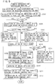
- the controller 30 mainly consists of the following devices; a road data calculator 31, a vehicle speed calculator 32, a road friction estimator 33, a road slope calculator 34, a standard deceleration calculator 35, a warning deceleration calculator 36, a forced deceleration calculator 37, a permissible lateral acceleration calculator 38, a permissible access speed calculator 39, a permissible deceleration calculator 40, an equivalent linear distance calculator 41, a required deceleration calculator 42, a passing judgement 43 and a warning deceleration controller 44.
- the road data calculator 31 calculates road geometry data of the road in front within a predetermined range, e.g., 300m, based on inputted data from the navigator 17 and memorizes them.
- the road data calculator 31 determines which curve is an objective of the operation and transmits the curvature RRn to the permissible access speed calculator 39 and the curvature RRn, the curve depth THn and the link length LSSn to the equivalent linear distance calculator 41.
- the road data detecting means consists of the navigator 17 and the road data calculator 31.
- the road data calculator 31 mainly consists of a node detector 31a, a Pn-1 Pn distance calculator 31b, a Pn Pn+l distance calculator 31c, a relative length judgment 31d, a mid-point calculator 31e, a mid-point-same-distance-point calculator 31f, a radius calculator 31g, a corrector 31h.
- a node detector 31a a Pn-1 Pn distance calculator 31b
- a Pn Pn+l distance calculator 31c a relative length judgment 31d
- a mid-point calculator 31e a mid-point-same-distance-point calculator 31f
- a radius calculator 31g a corrector 31h.
- the node detector 31a registers three consecutive nodes in the traveling direction of the vehicle or on the road selected by the driver, and names them the 1 st (first) node Pn-1, the 2 nd (second) node Pn and the 3 rd (third) node Pn+1, in turn from the closest. From the registered three nodes, the positional information of the 1 st (first) and 2 nd (second) nodes , Pn-l and Pn are outputted to the Pn-1 Pn distance calculator 31b, and the positional information of the 2 nd (second) and 3 rd (third) nodes, Pn and Pn+l are outputted to the Pn Pn+l distance calculator 31c.
- Positional data of Pn-1, Pn, and Pn+1 are (Xn-1,Yn-1), (Xn,Yn), and (Xn+1, Yn+1),respectively.
- Pn is the representative node of them.
- Curve data at points P1, P2, ..., and Pn are calculated by node combinations of (P0, P1, P2), (P1, P2, P3), ..., and(Pn-1, Pn, Pn+1), respectively.
- the Pn-1 Pn distance calculator 31b calculates a linear distance from Pn-l to Pn according to the positional information of Pn-l and Pn inputted from the node detector 31a, and sends the distance datum to the relative length judgment 31d and the corrector 31h.
- the Pn Pn+1 distance calculator 31c calculates a linear distance from Pn to Pn+l according to the positional information of Pn and Pn+l inputted from the node detector 31a, and sends the distance datum to the relative length judgment 31d and the corrector 31h.
- the relative length judgment 31d compares the linear distance from Pn-l to Pn inputted from the Pn-1 Pn distance calculator 31b and the linear distance from Pn to Pn+l inputted from the Pn Pn+l distance calculator 31c, so as to judge relative length. Data (position, distance) of the shorter linear distance are sent to the mid-point calculator 31e and the corrector 31h, while data (position, distance) of the longer linear distance are sent to the mid-point-same-distance-point calculator 31f.
- the comparison at the relative length judgment 31d shows an equal length for the both linear distances, either one can be used. It is set that the straight line connecting Pn-1 and Pn is regarded as the shorter straight line in this case. (It may be set that the straight line connecting Pn and Pn+l is regarded as the shorter straight line).
- the mid-point calculator 31e calculates half of the shorter linear distance and determines the mid point position on the shorter straight line.
- the mid-point-same-distance-point calculator 31f determines a mid-point-same-distance-point on the longer straight line at the position in half the distance of the shorter straight line from the 2 nd (second) node Pn.
- the mid-point-same-distance-point on the longer straight line connecting Pn and Pn+1 is named Pn,n+1, of which coordinates are represented by (Xn,n+1 Yn,n+1).
- K2 ((Xn - Xn-1) 2 + (Xn - Yn-1) 2 ) 1/2 /(2( (Xn+1 -Xn) 2 + (Yn+1 - Yn) 2 ) 1 / 2 )
- the positional data of the mid-point-same-distance-point Pn,n+l calculated by the mid-point-same-distance-point calculator 31f are sent to the radius calculator 31g.
- the radius calculator 31g determines a center "On" of the emerging curve on the road by creating a crossing point of a line that lies at the right angle to the shorter straight line (here, Pn-1 Pn) at the mid-point Pn-1,n and a line that lies at the right angle to the longer straight line (here, Pn Pn+1) at the mid-point-same-distance-point Pn, n+1.
- the radius calculator 31g calculates a radius of curvature Rn of the curve based on the determined center "On". The calculation results are sent to the corrector 31h.
- 0n Pn,n+1 + Pn,n+1
- the corrector 31h calculates a difference Deln between the radius of curvature Rn obtained by the radius calculator 31g and the distance Lon from the curve center On to the 2 nd (second) node Pn.
- the corrector 31h corrects the radius of curvature Rn so that the difference Deln be within the given error value.
- the given error value varies according to road with data from the navigator 17 (a road width D) and a shorter straight line distance judged by the relative length judgment 31d, the given error value being represented as ⁇ D.
- ⁇ is a constant to be set in accordance with the shorter straight line distance, and is hereinafter referred to as a node interval correction factor.
- the shorter a shorter straight line distance is the larger the node interval correction factor ⁇ is, resulting in less possibility of correction.
- ⁇ is 1.2
- ⁇ is 0.6
- ⁇ is o.3.
- Short intervals of nodes represent that the road is accurately drawn by nodes on the map, i.e., less correction is necessary.
- FIG.5 shows a detailed correction to be made by the corrector 31h.
- a vector from Pn-l to Pn is denoted by B1, and a vector from Pn to Pn+1 is denoted by B2.
- Lon ⁇
- the road data calculator 31 obtains radius of curvature Rn as described above, data of nodes with irregular intervals, as inputted from the navigator 17, can be used as they are.
- radius of curvature of travelling road can be determined quickly and accurately by simple calculation without data supplement or complex calculations.
- the continuity of radiuses of curvature determined for respective nodes are natural and the obtained data represent accurately an actual load geometry.
- calculated radius of curvature Rn always becomes smaller than actual radius of curvature. This is preferable for a warning deceleration control at approaching a curve to make a proper warning.
- Final road data of curve memorized in the road data calculator 31 may be those which are further reduced, for example neighboring small curves are treated as one large curve, or those which are processed by comparing with other road data obtained from other road data detecting means, e.g., a device which obtain road data by processing pictures taken by CCD camera.
- the vehicle speed calculator 32 comprising a running condition detecting means, receives respective wheel speeds from the wheel speed sensors 18fl, 18fr, 18rl and 18rr so that vehicle speed V is calculated by a predetermined formula, e.g., average of 4 wheel speeds. Vehicle speed V is sent to the road friction estimator 33, the road slope calculator 34 and the required deceleration calculator 42.
- the road friction estimator 33 receives steering wheel angle, yaw rate and vehicle speed V from the steering wheel angle sensor 19, the yaw rate sensor 20 and the vehicle speed calculator 32 respectively.
- road slope SL may be calculated by other way, e.g., utilizing altitude data available from a navigator installed on the vehicle or road geometry data made from picture data by CCD camera.
- the standard deceleration calculator 35 calculates a standard deceleration DXL3, based on the present running conditions at the point of operation, which include road surface friction coefficient ⁇ and road slope SL inputted from the road friction estimator 33 and the road slope calculator 34 respectively, and on estimated running condition in a curve.
- the standard deceleration DXL3 is transmitted to the warning deceleration calculator 36 and the forced deceleration calculator 37.
- DXL3 (m/S 2 )
- a basic standard deceleration DXL1 (m/S 2 ) is calculated by the following formula (13) from road surface friction coefficient ⁇ , gravitational acceleration g(m/S 2 ) and K4(e.g., 0.65) which is provided considering estimation tolerance of ⁇ , brake effectiveness on road surface and safety factor.
- DXL1 ⁇ g k4 Comparing DXL1 with K5 which is predetermined considering maximal deceleration in ordinary driving, for example 5.0m/s 2 (not a excessive deceleration), the smaller of the two is chosen as DXL2. By doing this, limitation is introduced.
- DXL3 DXL2+(SL/100) g
- DXL3 DXL2+(SL/100) g
- the warning deceleration calculator 36 receives a standard deceleration DXL3 from the standard deceleration calculator 35 and determines a warning control threshold namely a warning deceleration WDX (m/s 2 ), considering how to set warning level, i.e., warning dispatches when needed deceleration to prevent over speed in a curve exceeds a certain level against DXL3.
- warning control threshold is 50% of the standard deceleration DXL3.
- WDX 0.5 DXL3
- Warning deceleration WDX is sent to the equivalent linear distance calculator 41, the passing judgement 43 and the warning deceleration controller 44.
- the forced deceleration calculator 37 receives a standard deceleration DXL3 from the standard deceleration calculator 35 and calculates a forced control threshold namely a forced deceleration CDX (m/s 2 ), considering how to set forced control level, i.e., forced deceleration is carried out when needed deceleration to prevent over speed in a curve exceeds a certain level against DXL3.
- forced control threshold is 80% of the standard deceleration DXL3.
- CDX 0.8 DXL3 Forced deceleration CDX is sent to the passing judgement 43 and the warning deceleration controller 44.
- the permissible lateral acceleration calculator 38 receives road surface friction coefficient ⁇ from the road friction estimator 33 and calculates a permissible lateral acceleration AYL (m/s 2 ) by the following formula (17) based on the road surface friction coefficient ⁇ .
- AYL K6 ⁇ g K6 is a predetermined value considering estimation tolerance of ⁇ and tolerance of deceleration, being 0.5 in this embodiment.
- Permissible lateral acceleration AYV is sent to the permissible access speed calculator 39.
- the permissible access speed calculator 39 receives curvature RRn of the objective curve from the road data calculator 31 and permissible lateral acceleration AYL from the permissible lateral acceleration calculator 38.
- the calculator 39 calculates, e.g., by the following formula (18), a permissible access speed VAP(m/s) for passing through a curve with curvature RRn.
- VAP (AYL/RRn) 1/2
- Permissible lateral acceleration AYL is sent to the required deceleration calculator 42.
- the permissible lateral acceleration calculator 38 and the permissible access speed calculator 39 are provided to calculates permissible access speed VAP which composes permissible running conditions for passing through a curve.
- the permissible deceleration calculator 40 receives road surface friction coefficient ⁇ from the road friction estimator 33 and calculates a permissible deceleration AXL (m/s 2 ) in a curve by the following formula (20) referring to friction circle concept expressed in the equation (19).
- AYL 2 + AXL 2 ( ⁇ g) 2
- AXL ⁇ g ( 1 - K6 2 ) 1/2
- Permissible deceleration AXL is sent to the equivalent linear distance calculator 41.
- the equivalent linear distance calculator 41 receives curvature RRn of curve (including winding part of the road to the objective curve), curve depth THn and link length Lssn from the vehicle position to an objective curve from the road data calculator 31.
- the equivalent linear distance calculator 41 also receives warning deceleration WDX from the warning deceleration calculator 36.
- the equivalent linear distance calculator 41 calculates an equivalent linear distance EEL by the following formula (21), separating the road into straight part and winding part and counting the winding part to be converted into equivalent straight length.
- the length of an arc approximating the winding part is calculated by summation of each arc length ALn, which represents each bend of the winding part in the course to the objective curve.
- ALn is calculated by the following formula (22), counting road data of each bend, i.e., curvature RRn and curve depth THn.
- ALn THn/RRn
- the factor K7 is calculated by the following formula (23) from the permissible deceleration AXL and the warning deceleration WDX.
- K7 AXL/WDX and K7 ⁇ 1 It is obviously understood from the formulas (22) and (23) that a bend where permissible deceleration is limited to 1/2 is converted to a straight line with 1/2 length of arc of the bend.
- the equivalent linear distance calculator 41 is to provide a worth judging equivalent linear distance by correcting actual distance from point of operation (present position) to an objective curve (curve on the travelling road in front) based on road data.
- the correction converts actual length of the winding part into shorter equivalent linear distance according to curvature of the winding part.
- the required deceleration calculator 42 receives vehicle speed V, permissible access speed VAP and equivalent linear distance ELL from the vehicle speed calculator 32, the permissible access speed calculator 39 and the equivalent linear distance calculator 41 respectively, and then calculates a required deceleration RDX by the following formula (24).
- RDX is required during deceleration until reaching an objective curve for entering into the curve with the permissible access speed VAP.
- RDX (V 2 -VAP 2 )/ (2 ELL)
- Required deceleration RDX is sent to the passing judgement 43 and the warning deceleration control 44.
- the passing judgement 43 receives warning deceleration WDX, forced deceleration CDX and required deceleration RDX from the warning deceleration calculator 36, the forced deceleration calculator 37 and the required deceleration calculator 42 respectively, and then make judgement on whether or not forced deceleration control is needed to achieve the required deceleration RDX (RDX ⁇ CDX), whether or not the situation is at a level where forced deceleration control is not necessary but warning is required (CDX>RDX ⁇ WDX), or whether it is possible to pass without warning or forced deceleration control. Result of the judgement is sent to the warning deceleration control 44.
- warning deceleration calculator 36, the forced deceleration calculator 37, the required deceleration calculator 42 and the passing judgement 43 compose passing judgement means for judging possibility of passing through an objective curve according to equivalent linear distance ELL (worth judging distance), the standard deceleration DXL3 (estimated running condition) and permissible access speed VAP (permissible running condition).
- the warning deceleration controller 44 comprising warning and deceleration controlling means, receives master cylinder pressure, turn signal switch information, warning deceleration WDX, forced deceleration CDX, required deceleration RDX and result of judgement from the master cylinder pressure sensor 22, the turn signal switch 23,the warning deceleration calculator 36, the forced deceleration calculator 37, the required deceleration calculator 42 and the passing judgement 43 respectively.
- the warning deceleration controller 44 carries out control after confirming driver's decelerating operation and driver's intention to turn before entering into the curve.
- the controller 44 determines an aimed deceleration SDX and carries out deceleration control to achieve the aimed deceleration SDX.
- the controller 44 carries out warning control.
- the controller 44 calculates a deceleration PDX by the driver's operation from the master cylinder pressure. If PDX is larger than the required deceleration CDX, i.e., the driver's decelerating operation is effective enough, the controller 44 alters the forced deceleration control to warning control.
- the controller 44 judges that the driver has no intention to enter the curve and cancels both warning and forced deceleration controls.
- the controller 44 carries out forced deceleration control.
- an aimed deceleration SDX is determined from the required deceleration RDX with limitation, e.g., by selecting the smaller of the RDX and 5.0(m/s 2 ).
- necessary controls are carried out selectively out of the following controls; fuel cut and throttle closing controls (to be instructed to the engine control unit 24), fuel cut, throttle closing and shift down (to be instructed to the engine control unit 24 and the transmission control unit 25), fuel cut, throttle closing and braking (to be instructed to the engine control unit 24 and the brake control unit 26), fuel cut, throttle closing, shift down and braking (to be instructed to the engine control unit 24, the transmission control unit 25 and the brake control unit 26).
- deceleration PDX When the passing judgement 43 judges that situation is warning level (CDX>RDX ⁇ WDX), or situation has changed to warning level from forced deceleration level, deceleration PDX by the driver's decelerating operation is calculated from master cylinder pressure. If the deceleration PDX is larger than the warning deceleration WDX, i.e., the driver's decelerating operation is effective enough, warning is not carried out.
- the controller 44 judges that the driver has no intention to enter the curve and cancels warning control.
- the controller carries out warning by the display 27 or the loudspeaker 28.
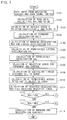
- FIG.7 and FIG.8 show flow charts of vehicle dynamic control carried out by the controller 30.
- S101 S means step
- the controller 30 receives data and signals from the respective device, switch and sensors as shown below;
- the program goes to S102, where the road data calculator 31 calculates road geometry data of the road in front within a predetermined range, e.g., 300m, based on inputted data from the navigator 17.
- a predetermined range e.g. 300m
- the program goes to S103, where the vehicle speed calculator 32 calculates a vehicle speed V based on the 4 (four) wheel speeds, the road friction estimator 33 estimates a road surface fiction coefficient ⁇ based on the steering wheel angle, the yaw rate and the vehicle speed V and the road slope calculator 34 calculates road slope SL by the formula (12) based on the vehicle speed V and the longitudinal acceleration Gx. Then goes to S104.
- the standard deceleration calculator 35 calculates a standard deceleration DXL3 by the formulas (13) and (14) based on the road surface friction coefficient ⁇ and the road slope SL.
- the warning deceleration calculator 36 calculates a warning deceleration WDX by the formula (15) based on the standard deceleration DXL3 and the forced deceleration calculator 37 calculates a forced deceleration CDX by the formula (16) based on the standard deceleration DX3.
- the permissible lateral acceleration calculator 38 calculates a permissible lateral acceleration AYL by the formula (17) based on the road surface friction coefficient ⁇ .
- the permissible deceleration calculator 40 calculates a permissible deceleration AXL by the formula (20) based on the road surface friction coefficient ⁇ , referring to relation to the permissible lateral acceleration AYL calculated at S106, namely friction circle relation.
- the equivalent linear distance calculator 41 calculates an equivalent linear distance ELL by the formula (21) based on the curvature RRn of the curve (inclusive of bends of winding part of road till the curve), the curve depth THn, the link length Lssn, the permissible deceleration AXL and the warning deceleration WDX.
- the permissible access speed calculator 39 calculates a permissible access speed VAP by the formula (18) based on the curvature RRn of the objective curve and the permissible lateral acceleration AYL.
- the required deceleration calculator 42 calculates a required deceleration RDX for entering the objective curve by the formula (24) based on the vehicle speed V, the equivalent linear distance ELL and the permissible access speed VAP.
- the passing judgement 43 compares the required deceleration RDX and the warning deceleration WDX.
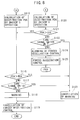
- RDX is larger or equal to WDX (RDX ⁇ WDX)
- RDX is smaller than WDX (RDX ⁇ WDX)
- the program goes to S114.
- the warning deceleration controller 44 cancels both warning and deceleration controls and the program stops.
- a deceleration PDX is calculated based on the master cylinder pressure resulting from the driver's operation. Then goes to S116, where PDX is compared with the warning deceleration WDX.
- the program goes to S120 where a deceleration PDX is calculated based on the master cylinder pressure resulting from the driver's operation. Then goes to S121 where PDX is compared with the forced deceleration CDX.
- path to the objective curve is processed in a form of the equivalent linear distance considering permissible decelerations at winding part of the path referring to the concept of friction circle.
- FIG. 9 shows a flow chart of routine of forced deceleration control at S125 carried out by the warning deceleration controller 44.
- an aimed deceleration SDX is determined by adding some limitation to the required deceleration RDX, for example, the smaller of the required deceleration RDX and 5.0(m/s 2 ) is taken as the aimed deceleration SDX.
- the program goes to S202 where an estimated deceleration D1 is calculated, supposing that the engine control unit 24 is instructed to carry out fuel cut and complete closing of throttle.
- the program goes to S 203 where the estimated deceleration D1 and the aimed deceleration SDX are compared.
- D1 is larger than SDX (D1>SDX), namely the aimed deceleration SDX is achievable by fuel cut and closing of throttle
- the program goes to S204 where the engine control unit 24 is instructed to carry out fuel cut and closing of throttle. And then the program goes out the routine.
- the program goes to S209 where the brake control unit 26 is instructed to apply the brake pressure BP then goes to S210.
- the display 27 or the loudspeaker 28 alarms the driver that the brake control unit 26 carries out braking, then the program goes to S211 where the engine control unit 24 is instructed to carry out fuel cut and complete closing of throttle. And then goes to S212 where the transmission control unit 25 is instructed to carry out available shift down and goes out the routine.
- the estimated deceleration D2 and the aimed deceleration SDX are compared.
- D2 is larger than SDX (D2>SDX), namely the aimed deceleration is achievable by fuel cut, closing of throttle and transmission shift down
- the program goes to S215 where shift position is selected among available shift positions for down shift in order to achieve the aimed deceleration CDX together with fuel cut and closing of throttle.
- the program goes to S211 where the engine control unit 24 is instructed to carry out fuel cut and closing of throttle.
- the transmission control unit 25 is instructed to carry out shift down and the program goes out the routine.
- the program goes to S209 where the brake control unit 26 is instructed to apply the brake pressure BP then goes to S210.
- the display 27 or the loudspeaker 28 alarms the driver that the brake control unit 26 carries out braking, then the program goes to S211 where the engine control unit 24 is instructed to carry out fuel cut and complete closing of throttle. And then goes to S212 where the transmission control unit 25 is instructed to carry out available shift down and goes out the routine.
- the passing judgement means judges possibility of passing through a curve by comparison of a required deceleration and a warning deceleration or by comparison of a required deceleration and a forced deceleration, based on an equivalent linear distance as worth judging distance, a standard deceleration as estimated running condition, and a permissible access speed as permissible running condition. It is possible to judge based on combination of other running conditions, e.g., vehicle speed, deceleration, distance, time and lateral acceleration.
- Deceleration control by combination of an engine control unit, a transmission control unit and a brake control unit. Deceleration control may be carried out by one of the three control units or combination of two of the three.
- the engine control unit carries out fuel cut and throttle closing for forced deceleration.
- decreasing of charged pressure can be used for forced deceleration control.
- other engine controls e.g., changes of fuel injection timing and ignition timing can be used for forced deceleration control.
Abstract
Description
- This invention relates to a vehicle dynamic control system which carries out warning and decelerating control in order to safely pass through a curve on travelling road in front of a vehicle.
- Recently developed are several kinds of technology wherein road map data, provided from a navigator installed on a vehicle, are processed into road geometry data. Warning and decelerating controls are carried out after judgement on possibility of passing through the curve in front based on road data including curvature of the curve, and vehicle speed.
- For example, the Japanese Patent Laid-open No. 194886/1996 disclosed warning and vehicle speed control technology. Road data of a curve on traveling road in front are calculated based on road map data provided from a navigator. A permissible lateral acceleration which is an allowable limit to enter into the curve and a foreseeable lateral acceleration at entrance of the curve if the vehicle goes on at the present speed are calculated and compared. When the foreseeable lateral acceleration is larger than the permissible lateral acceleration, the present speed is judged too high to enter into the curve in front, namely in over speed condition and the warning and vehicle speed control is carried out.
- When judging possibility of passing through a curve, the approaching road to the curve is deemed to be a straight line during which certain deceleration is applied to reduce an initial speed to a speed which is slow enough for passing through the curve.
- Thinking about a case where the road to the objective curve is not a straight line, the judgement may not be made accurately by the calculation. In the case that the road is not a straight line, lateral acceleration occurs on the vehicle resulting in forced reduction of deceleration based on relation between longitudinal acceleration and lateral acceleration. Thus over speed judgement may become tolerant.
- In order to eliminate the influence of the error, it may be a countermeasure to calculate permissible decelerations for all bends and carry out control. But as enormous calculations are required, processing speed becomes too slow for practical use.
- The present invention provides a vehicle dynamic control system which can improve accuracy of over speed judgement even in the case where a road to an objective curve is not a straight line while minimizing increment of calculation load, at a judgement on whether present speed is over speed or not after recognizing road geometry data of a curve on travelling road in front.
- In order to achieve the aforementioned object, a vehicle dynamic control system according to the present invention comprises a running condition detecting means for detecting running conditions of a vehicle, a road data detecting means for detecting road data of a traveling road in front of the vehicle, a worth judging distance calculating means for calculating a worth judging distance from a point of operation to a curve on the traveling road in front of the vehicle based on the road data, the worth judging distance being corrected and reduced according to curvatures of winding part of the road between the point of operation and the curve, a passing judgement means for judging possibility of passing through the curve by the vehicle according to the worth judging distance calculated by the worth judging distance calculating means, and a warning and deceleration control means for putting a warning means into operation and activating at least one of predetermined decelerating means according to judgement of the passing judgement means.
- In the vehicle dynamic control system of the present invention, the running condition detecting means detects vehicle running conditions and the road data detecting means detects road data of the travelling road in front. The worth judging distance calculating mean calculates the worth judging distance from the point of operation to the curve, by correcting and reducing it according to curvatures of winding part of the road between the point of operation and the curve. The passing judgement means judges possibility of passing through the curve according to the worth judging distance calculated by the worth judging distance calculating means. And, the warning and deceleration control means puts the warning means into operation and activates at least one of the predetermined decelerating means according to the judgement.
- In a vehicle dynamic control system having the features of claim 2, the worth judging distance calculating means determines the worth judging distance, referring to a permissible deceleration applicable at the winding part of the road in addition to the curvatures of the winding part of the road, the worth judging distance calculating means calculating the permissible deceleration by friction circle relation between longitudinal and lateral accelerations. Thus the concept of friction circle is reflected in the control by the system so that precise control can be done.
- In a vehicle dynamic control system having the features of claim 3, the passing judgement means judges the possibility of passing through the curve according to estimated running conditions based on running conditions at the point of operation and permissible running conditions based on running conditions for passing through the curve.
- In a vehicle dynamic control system having the features of claim 4, the estimated running conditions include a standard deceleration applicable at the point of operation, the permissible running conditions includes a permissible access speed for passing through the curve, the passing judgement means calculates a required deceleration to be applied until reaching the curve based on the permissible access speed, a vehicle speed at the point of operation and the worth judging distance, and the passing judgement means judges the possibility of passing through the curve by comparing the standard deceleration and the required deceleration in a predetermined manner. Namely, deceleration is criterion for the judgement so that precise control result can be obtained.
- By way of example only, a specific embodiment of the present invention will now be described, with reference to the accompanying drawings, in which:
- FIG.1 is a functional block diagram showing a vehicle dynamic control system;
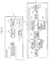
- Fig.2 is an illustration showing an outlined construction of a vehicle equipped with a vehicle dynamic control system;
- FIG.3 is an illustration showing calculation function of radius of curvature in a road data calculator;
- FIG.4 is an illustration showing how to determine radius of curvature;
- FIG.5 is an illustration showing how to correct the obtained radius of curvature;
- FIG.6 is an illustration showing examples of note data actually obtained from a navigator;
- FIG.7 is a flow chart showing vehicle dynamic control;
- FIG.8 is a flow chart continued from FIG.7;
- FIG.9 is a flow chart showing an execution routine of forced deceleration control;
-
- A preferred embodiment of the present invention is described according to the accompanying drawings. Referring to FIG.2, numeral 1 shows a 4-wheel driven vehicle having a center differential and an automatic transmission.
- Driving force, generated by an engine 2 installed in front of the vehicle, is transmitted to the automatic transmission 3 (shown including a torque converter) located next to the engine 2, and further transmitted to a center differential 4 through a transmission output shaft 3a. The driving force is delivered to a rear final reduction 8 through a rear drive shaft 5, a propeller shaft 6 and a drive pinion 7 in turn and also delivered to a front final reduction 10 through a front drive shaft 9. The automatic transmission 3, the center differential 4 and the front final reduction 10 and so on are integrally accommodated in a case (not shown). The driving force inputted to the rear final reduction 8 is transmitted to a left rear wheel 12rl through a left rear drive shaft 11rl and also transmitted to a right rear wheel 12rr through a right rear drive shaft 11rr. The driving force inputted to the front final reduction 10 is transmitted to a left front wheel 12fl through a left front drive shaft 11fl and also transmitted to a right front wheel 12fr through a right front drive shaft 11fr.
- A brake actuator 13 is hydraulically connected to a master cylinder 15 connected to a brake pedal 14 which is operated by a driver. When the driver operates the brake pedal 14, the master cylinder 15 pressurizes brake fluid and delivers the pressure through the brake actuator 13 to each of 4 wheel cylinders of the 4 wheels 12fl, 12fr, 12rl and 12rr. They are a front left wheel cylinder 16fl, a front right wheel cylinder 16fr, a rear left wheel cylinder 16rl and a rear right wheel cylinder 16rr.
- The brake actuator 13, which is a hydraulic unit comprising a pressurizing device, a reducing valve and an intensifier, can apply brake pressure to the wheel cylinders 16fl, 16fr, 16rl and 16rr respectively, independently and controllably corresponding to inputted signals.
- The vehicle 1 is equipped with a navigator 17. In general, as shown in FIG. 3, the navigator 17 consists mainly of a vehicle position detection sensor 17a, an auxiliary memory 17b, a display 17c, a control section 17d, and a processing unit 17e. The vehicle position detection sensor 17a gathers running information related to vehicle position. The sensor 17a consists mainly of a GPS (Global Positioning System) receiver to receive positioning signals from GPS satellites so as to determine the position of the vehicle, a geomagnetic sensor to detect the absolute running direction of the vehicle, and wheel speed sensors outputting pulse signals synchronized with wheel rotations.
- The auxiliary memory 17b is a CD-ROM device, loading a CD -ROM storing road map information including road data and topographical data. The CD-ROM stores road map information in a plurality of hierarchical levels in various scales and further stores road kind information such as motor ways, ordinary national roads and local roads, passage conditions of intersections and road widths. Road geometry data included in the road map information consist of node data with given intervals. Road width data are reduced in several rankings as shown below and stored;
- W1=O :
- not investigated yet
- W1=1 :
- 0 m < W < 3 m
- W1=2 :
- 3 m < W < 5.5 m
- W1=3 :
- 5.5 m < W < 13 m
- W1=4 :
- 13 m < W
- The display 17c is a liquid crystal display which displays maps, the vehicle position (latitude, longitude and altitude), direction, the position of vehicle on the map, and the optimum routing up to a destination. A touch panel, the control section 17d is integrated in the display 17c (liquid crystal display) to provide control functions such as map scale change and display switching for detailed place name display, area information display and route guidance display.
- The processing unit 17e composes the vehicle running information inputted from the vehicle position detection sensor 17a and the road map information registered from the auxiliary memory 17b, while making map matching and other processing. The results are sent to the display 17c following to an operating signal sent from the control section 17d, so as to display the present position of the vehicle, a map of the neighborhood, an optimum route to destination and other information. The node data, the vehicle position and the road width information are outputted to a controller 30 to be mentioned later.
- The controller 30 is connected to wheel speed sensors 18fl, 18fr,18rl and 18rr detecting wheel speeds of the wheels 12fl, 12fr, 12rl and 12rr respectively, to a steering wheel angle sensor 19 detecting steering wheel angle M of the vehicle 1, a yaw rate sensor 20 detecting yaw rate γ, a longitudinal acceleration sensor 21 detecting longitudinal acceleration Gx, a master cylinder pressure sensor 22 detecting master cylinder pressure and a turn signal switch 23 detecting turn signal operation so as to receive respective signals.
- The controller 30 is also connected for communication to control units of respective decelerating means, i.e., an engine control unit 24 for the engine 2, a transmission control unit 25 for the transmission 3 and a brake control unit 26 for the brake actuator 13.
- The engine control unit 24, which is to carry out engine controls such as fuel injection control, ignition timing control, air fuel ratio control, charged pressure control and throttle opening control, delivers the controller 30 with fuel cut information and throttle opening control information. The engine control unit 24 receives signal for carrying out fuel cut, and then cuts fuel. Receiving signal for carrying out complete throttle closing, the control unit 24 closes throttle completely.
- The transmission control unit 25, which is to carry out transmission controls such as gear speed change control, lock-up control and line pressure control, delivers the controller 30 with information of shift lever position and gear position. Receiving signal for carrying out shift down from the controller, the transmission control unit 25 carries out shift down.
- The brake control unit 26, which is to carry out anti-locking brake control and automatic brake control in connection with the brake actuator 13, delivers the controller 30 with information of present braking situation. Receiving signals for braking or increasing braking force from the controller 30, the brake control unit 26 carries out braking or increases braking force, namely automatic braking.
- Furthermore, the controller 30 is connected to a display 27 (for common use with the display of the navigator 17) and a loudspeaker 28, which are provided in the compartment as warning means, so that warnings and alarms by voice, buzzer and display are carried out. The following are examples of warnings and alarms;
- "Curve ahead. Speed down." when drawing driver's attention to over speed;
- "Over speed. Deceleration is done." when carrying out forced deceleration control;
- "Braked for speed down." when automatic braking is applied for forced deceleration control;
- Blinking or lighting display for informing over speed, forced deceleration control, automatic braking for forced deceleration control and so on
- The controller 30 determines a distance from the present position (point of operation) to the curve on the travelling road in front as an equivalent linear distance by calculation based on data inputted from respective sensors and switch. And the controller 30 also determines a standard deceleration which is applicable in the present running conditions and a permissible access speed for passing through the curve in front based on road geometry of the curve. Then a required deceleration to be applied till entering the curve is calculated based on the present speed, the equivalent linear distance and the permissible access speed. The required deceleration being compared with the standard deceleration in a predetermined manner, decision is made for warning and forced deceleration controls so that the controller 30 outputs instructions to the display 27, the loudspeaker 28, the engine control unit 24, the transmission control unit 25 and the brake control unit 26.
- The controller 30 mainly consists of the following devices; a road data calculator 31, a vehicle speed calculator 32, a road friction estimator 33, a road slope calculator 34, a standard deceleration calculator 35, a warning deceleration calculator 36, a forced deceleration calculator 37, a permissible lateral acceleration calculator 38, a permissible access speed calculator 39, a permissible deceleration calculator 40, an equivalent linear distance calculator 41, a required deceleration calculator 42, a passing judgement 43 and a warning deceleration controller 44.
- The road data calculator 31 calculates road geometry data of the road in front within a predetermined range, e.g., 300m, based on inputted data from the navigator 17 and memorizes them. The road geometry data include position(Xn,Yn) of representative node Pn; distance Ln between node Pn-l and node Pn; final radius of curvature Rn; curvature
- Detailed explanation on how to calculate radius of curvature Rn will follow. As shown in FIG.3, the road data calculator 31 mainly consists of a node detector 31a, a Pn-1 Pn distance calculator 31b, a Pn Pn+l distance calculator 31c, a relative length judgment 31d, a mid-point calculator 31e, a mid-point-same-distance-point calculator 31f, a radius calculator 31g, a corrector 31h. As shown in FIG. 6, out of the node data inputted from the navigator 17, the node detector 31a registers three consecutive nodes in the traveling direction of the vehicle or on the road selected by the driver, and names them the 1st (first) node Pn-1, the 2nd (second) node Pn and the 3rd (third) node Pn+1, in turn from the closest. From the registered three nodes, the positional information of the 1st (first) and 2nd (second) nodes , Pn-l and Pn are outputted to the Pn-1 Pn distance calculator 31b, and the positional information of the 2nd (second) and 3rd (third) nodes, Pn and Pn+l are outputted to the Pn Pn+l distance calculator 31c. Positional data of Pn-1, Pn, and Pn+1 are (Xn-1,Yn-1), (Xn,Yn), and (Xn+1, Yn+1),respectively. Pn is the representative node of them. Curve data at points P1, P2, ..., and Pn are calculated by node combinations of (P0, P1, P2), (P1, P2, P3), ..., and(Pn-1, Pn, Pn+1), respectively.
- The Pn-1 Pn distance calculator 31b calculates a linear distance from Pn-l to Pn according to the positional information of Pn-l and Pn inputted from the node detector 31a, and sends the distance datum to the relative length judgment 31d and the corrector 31h. The Pn Pn+1 distance calculator 31c calculates a linear distance from Pn to Pn+l according to the positional information of Pn and Pn+l inputted from the node detector 31a, and sends the distance datum to the relative length judgment 31d and the corrector 31h.
- The relative length judgment 31d compares the linear distance from Pn-l to Pn inputted from the Pn-1 Pn distance calculator 31b and the linear distance from Pn to Pn+l inputted from the Pn Pn+l distance calculator 31c, so as to judge relative length. Data (position, distance) of the shorter linear distance are sent to the mid-point calculator 31e and the corrector 31h, while data (position, distance) of the longer linear distance are sent to the mid-point-same-distance-point calculator 31f. When the comparison at the relative length judgment 31d shows an equal length for the both linear distances, either one can be used. It is set that the straight line connecting Pn-1 and Pn is regarded as the shorter straight line in this case. (It may be set that the straight line connecting Pn and Pn+l is regarded as the shorter straight line).
- An explanation will follow for the case the straight line connecting Pn-1 Pn is shorter than the straight line connecting Pn and Pn+1. According to the data (position, distance) of the shorter straight line inputted from the relative length judgment 31d, the mid-point calculator 31e calculates half of the shorter linear distance and determines the mid point position on the shorter straight line. Here, the mid point on the shorter straight line connecting Pn-l and Pn is named Pn-1, n of which coordinates are represented by (Xn-1,n , Yn-1,n).
- According to the data (position, distance) of the longer straight line inputted from the relative length judgment 31d and the half of the shorter linear distance inputted from the mid-point calculator 31e, the mid-point-same-distance-point calculator 31f determines a mid-point-same-distance-point on the longer straight line at the position in half the distance of the shorter straight line from the 2nd (second) node Pn. Here, the mid-point-same-distance-point on the longer straight line connecting Pn and Pn+1 is named Pn,n+1, of which coordinates are represented by (Xn,n+1 Yn,n+1).
- According to the positional data of the mid-point Pn-1,n inputted from the mid point calculator 31e and the positional data of a mid-point-same-distance-point Pn, n+l calculated by the mid-point-same-distance-point calculator 31f, the radius calculator 31g, as shown in FIG. 4, determines a center "On" of the emerging curve on the road by creating a crossing point of a line that lies at the right angle to the shorter straight line (here, Pn-1 Pn) at the mid-point Pn-1,n and a line that lies at the right angle to the longer straight line (here, Pn Pn+1) at the mid-point-same-distance-point Pn, n+1. Then, the radius calculator 31g calculates a radius of curvature Rn of the curve based on the determined center "On". The calculation results are sent to the corrector 31h. I.e.,
- The distance Lon from the curve center 0n to the curve representative node,i.e., the 2nd (second) node Pn is obtained from the following formula(8):
- The corrector 31h calculates a difference Deln between the radius of curvature Rn obtained by the radius calculator 31g and the distance Lon from the curve center On to the 2nd (second) node Pn. When the difference Deln exceeds a given error value (to be mentioned later), the corrector 31h corrects the radius of curvature Rn so that the difference Deln be within the given error value. The given error value varies according to road with data from the navigator 17 (a road width D) and a shorter straight line distance judged by the relative length judgment 31d, the given error value being represented as αD. α is a constant to be set in accordance with the shorter straight line distance, and is hereinafter referred to as a node interval correction factor. The wider the road width D is, the bigger the given error value is, resulting in less possibility of correction. That is to represent a reality that the wider a road width is the bigger a radius of curvature is.
- As with the node interval correction factor α, the shorter a shorter straight line distance is, the larger the node interval correction factor α is, resulting in less possibility of correction. For example, when the shorter straight line distance is shorter than 20m, α is 1.2, when the shorter straight line distance is middle namely shorter than 100m, α is 0.6, and when the shorter line distance is longer than 100m, α is o.3. Short intervals of nodes represent that the road is accurately drawn by nodes on the map, i.e., less correction is necessary.
- FIG.5 shows a detailed correction to be made by the corrector 31h. A vector from Pn-l to Pn is denoted by B1, and a vector from Pn to Pn+1 is denoted by B2.
- Based on the radius of curvature Rn, having been corrected by the corrector 31h or not corrected as the difference Deln is smaller than the given error value, the road data calculator 31 calculates curvature
- Since the road data calculator 31 obtains radius of curvature Rn as described above, data of nodes with irregular intervals, as inputted from the navigator 17, can be used as they are. Thus radius of curvature of travelling road can be determined quickly and accurately by simple calculation without data supplement or complex calculations. The continuity of radiuses of curvature determined for respective nodes are natural and the obtained data represent accurately an actual load geometry. Further, when possible calculation errors occur, calculated radius of curvature Rn always becomes smaller than actual radius of curvature. This is preferable for a warning deceleration control at approaching a curve to make a proper warning.
- With provision of the corrector 31h for correcting radius of curvature Rn, it is possible to calculate radius of curvature Rn accurately. Furthermore, with the provision to make the given error value changeable depending on actual road widths and node intervals, more accurate calculations can be done. In other words, in order to represent a reality that the wider a road width is, the bigger a radius of curvature is, it is so set that the wider a road width D is, the bigger the given error value is, resulting in less possibility of correction. In order to reflect a fact that short intervals of nodes represent that the road is accurately drawn by nodes on the map, it is so set that the shorter a shorter straight line distance is, the larger node interval correction factor α is, resulting in less possibility of correction.
- Final road data of curve memorized in the road data calculator 31 may be those which are further reduced, for example neighboring small curves are treated as one large curve, or those which are processed by comparing with other road data obtained from other road data detecting means, e.g., a device which obtain road data by processing pictures taken by CCD camera.
- The vehicle speed calculator 32, comprising a running condition detecting means, receives respective wheel speeds from the wheel speed sensors 18fl, 18fr, 18rl and 18rr so that vehicle speed V is calculated by a predetermined formula, e.g., average of 4 wheel speeds. Vehicle speed V is sent to the road friction estimator 33, the road slope calculator 34 and the required deceleration calculator 42.
- The road friction estimator 33, estimating road surface friction coefficient µ by calculation, e.g., an estimating method disclosed by the inventor in the Japanese Patent Laid-open No. 2274/1996, receives steering wheel angle, yaw rate and vehicle speed V from the steering wheel angle sensor 19, the yaw rate sensor 20 and the vehicle speed calculator 32 respectively.
- The road friction estimator 33, also comprising a running condition detecting means, estimates road surface friction coefficient µ by calculation based on steering wheel angle, yaw rate and vehicle speed V, and sends road surface friction coefficient µ to the standard deceleration calculator 35, the permissible acceleration calculator 38 and the permissible deceleration calculator 40. Estimation is achieved by: firstly calculating actual cornering power of front and rear wheels of the vehicle based on steering wheel angle, yaw rate and vehicle speed V by solving equation of motion of the vehicle lateral movement; secondary calculating theoretically maximum cornering power on highµ (µ=1.0); finally estimating road surface friction coefficient µ from ratio of the actual cornering power and the theoretically maximum cornering power.
- The road slope calculator 34, also comprising a running condition detecting means, calculates road slope SL from data of longitudinal acceleration Gx and vehicle speed V inputted from the longitudinal acceleration sensor 21 and the vehicle speed calculator 32 respectively and sends road slope SL to the standard deceleration calculator 35. Calculation of road slope SL is carried out by the following formula (12).
- SL(%):
- Positive figure means up-hill slope.
- Gx(m/S2):
- longitudinal acceleration
- g(m/S2):
- gravitational acceleration
- Besides the formulas (12) and (12)', road slope SL may be calculated by other way, e.g., utilizing altitude data available from a navigator installed on the vehicle or road geometry data made from picture data by CCD camera.
- The standard deceleration calculator 35 calculates a standard deceleration DXL3, based on the present running conditions at the point of operation, which include road surface friction coefficient µ and road slope SL inputted from the road friction estimator 33 and the road slope calculator 34 respectively, and on estimated running condition in a curve. The standard deceleration DXL3 is transmitted to the warning deceleration calculator 36 and the forced deceleration calculator 37.
- Explanation on how to calculate DXL3 (m/S2) will follow. Firstly, a basic standard deceleration DXL1 (m/S2) is calculated by the following formula (13) from road surface friction coefficientµ, gravitational acceleration g(m/S2) and K4(e.g., 0.65) which is provided considering estimation tolerance of µ, brake effectiveness on road surface and safety factor.
- The warning deceleration calculator 36 receives a standard deceleration DXL3 from the standard deceleration calculator 35 and determines a warning control threshold namely a warning deceleration WDX (m/s2), considering how to set warning level, i.e., warning dispatches when needed deceleration to prevent over speed in a curve exceeds a certain level against DXL3. In this embodiment warning control threshold is 50% of the standard deceleration DXL3.
- The forced deceleration calculator 37 receives a standard deceleration DXL3 from the standard deceleration calculator 35 and calculates a forced control threshold namely a forced deceleration CDX (m/s2), considering how to set forced control level, i.e., forced deceleration is carried out when needed deceleration to prevent over speed in a curve exceeds a certain level against DXL3. In this embodiment forced control threshold is 80% of the standard deceleration DXL3.
- The permissible lateral acceleration calculator 38 receives road surface friction coefficient µ from the road friction estimator 33 and calculates a permissible lateral acceleration AYL (m/s2) by the following formula (17) based on the road surface friction coefficient µ.
- The permissible access speed calculator 39 receives curvature RRn of the objective curve from the road data calculator 31 and permissible lateral acceleration AYL from the permissible lateral acceleration calculator 38. The calculator 39 calculates, e.g., by the following formula (18), a permissible access speed VAP(m/s) for passing through a curve with curvature RRn.
- The permissible deceleration calculator 40 receives road surface friction coefficient µ from the road friction estimator 33 and calculates a permissible deceleration AXL (m/s2) in a curve by the following formula (20) referring to friction circle concept expressed in the equation (19).
- The equivalent linear distance calculator 41 receives curvature RRn of curve (including winding part of the road to the objective curve), curve depth THn and link length Lssn from the vehicle position to an objective curve from the road data calculator 31. The equivalent linear distance calculator 41 also receives warning deceleration WDX from the warning deceleration calculator 36. And the equivalent linear distance calculator 41 calculates an equivalent linear distance EEL by the following formula (21), separating the road into straight part and winding part and counting the winding part to be converted into equivalent straight length.
- Thus, the equivalent linear distance calculator 41 is to provide a worth judging equivalent linear distance by correcting actual distance from point of operation (present position) to an objective curve (curve on the travelling road in front) based on road data. The correction converts actual length of the winding part into shorter equivalent linear distance according to curvature of the winding part.
[0081] - As an equivalent linear distance is determined by consideration of permissible decelerations at respective bends of winding part of a road to an objective curve, passing judgement for each of various curves can be done simply with equivalent linear distance so that control preciseness can be up-graded by minimal calculations.
- In the course of calculating an equivalent linear distance ELL by the equivalent linear distance calculator 41, used as variable is permissible deceleration AXL calculated by the permissible deceleration calculator 40 from road surface friction coefficient µ counting friction circle concept. Thus, reflected accurately in the calculation is naturally incurred limitation of applicable deceleration while lateral acceleration occurs at the same time, due to relation of lateral and longitudinal accelerations, so that reliable control can be carried out.
- The required deceleration calculator 42 receives vehicle speed V, permissible access speed VAP and equivalent linear distance ELL from the vehicle speed calculator 32, the permissible access speed calculator 39 and the equivalent linear distance calculator 41 respectively, and then calculates a required deceleration RDX by the following formula (24). RDX is required during deceleration until reaching an objective curve for entering into the curve with the permissible access speed VAP.
- The passing judgement 43 receives warning deceleration WDX, forced deceleration CDX and required deceleration RDX from the warning deceleration calculator 36, the forced deceleration calculator 37 and the required deceleration calculator 42 respectively, and then make judgement on whether or not forced deceleration control is needed to achieve the required deceleration RDX (RDX≧CDX), whether or not the situation is at a level where forced deceleration control is not necessary but warning is required (CDX>RDX≧WDX), or whether it is possible to pass without warning or forced deceleration control. Result of the judgement is sent to the warning deceleration control 44.
- Namely the warning deceleration calculator 36, the forced deceleration calculator 37, the required deceleration calculator 42 and the passing judgement 43 compose passing judgement means for judging possibility of passing through an objective curve according to equivalent linear distance ELL (worth judging distance), the standard deceleration DXL3 (estimated running condition) and permissible access speed VAP (permissible running condition).
- The warning deceleration controller 44, comprising warning and deceleration controlling means, receives master cylinder pressure, turn signal switch information, warning deceleration WDX, forced deceleration CDX, required deceleration RDX and result of judgement from the master cylinder pressure sensor 22, the turn signal switch 23,the warning deceleration calculator 36, the forced deceleration calculator 37, the required deceleration calculator 42 and the passing judgement 43 respectively.
- At every result of judgement, the warning deceleration controller 44 carries out control after confirming driver's decelerating operation and driver's intention to turn before entering into the curve. When forced deceleration control is required, the controller 44 determines an aimed deceleration SDX and carries out deceleration control to achieve the aimed deceleration SDX. Or when warning is necessary, the controller 44 carries out warning control.
- When the passing judgement 43 judges that forced control is required (RDX≧CDX), the controller 44 calculates a deceleration PDX by the driver's operation from the master cylinder pressure. If PDX is larger than the required deceleration CDX, i.e., the driver's decelerating operation is effective enough, the controller 44 alters the forced deceleration control to warning control.
- If the turning switch 23 is ON though the driver's decelerating operation is not effective, the controller 44 judges that the driver has no intention to enter the curve and cancels both warning and forced deceleration controls.
- If the case is not the above, namely the driver neither carries out decelerating operation nor has intention to turn before the curve, i.e. the vehicle is going to the objective curve, the controller 44 carries out forced deceleration control.
- In the forced deceleration control, firstly an aimed deceleration SDX is determined from the required deceleration RDX with limitation, e.g., by selecting the smaller of the RDX and 5.0(m/s2). In order to achieve the aimed deceleration SDX, necessary controls are carried out selectively out of the following controls; fuel cut and throttle closing controls (to be instructed to the engine control unit 24), fuel cut, throttle closing and shift down (to be instructed to the engine control unit 24 and the transmission control unit 25), fuel cut, throttle closing and braking (to be instructed to the engine control unit 24 and the brake control unit 26), fuel cut, throttle closing, shift down and braking (to be instructed to the engine control unit 24, the transmission control unit 25 and the brake control unit 26).
- When the passing judgement 43 judges that situation is warning level (CDX>RDX≧WDX), or situation has changed to warning level from forced deceleration level, deceleration PDX by the driver's decelerating operation is calculated from master cylinder pressure. If the deceleration PDX is larger than the warning deceleration WDX, i.e., the driver's decelerating operation is effective enough, warning is not carried out.
- If the turning switch 23 is ON though the deceleration PDX by the driver's decelerating operation is smaller or equal to the warning deceleration WDX, the controller 44 judges that the driver has no intention to enter the curve and cancels warning control.
- If the case is not the above, namely the driver neither carries out decelerating operation nor has intention to turn before the curve, i.e. the vehicle is going to the objective curve, the controller carries out warning by the display 27 or the loudspeaker 28.
- Operations described above are explained referring to flow charts shown in FIG.7, FIG.8 and FIG. 9. FIG.7 and FIG.8 show flow charts of vehicle dynamic control carried out by the controller 30. When this control program starts, the program goes to S101 (S means step) where the controller 30 receives data and signals from the respective device, switch and sensors as shown below;
- Node data, vehicle position, road width data from the navigator 17
- Respective wheel speeds from the wheel speed sensors 18fl, 18fr, 18rl and 18rr
- Steering wheel angle from the steering wheel sensor 19
- Yaw rate from the yaw rate sensor 20
- Longitudinal acceleration Gx from the longitudinal acceleration sensor 21
- Master cylinder pressure from the master cylinder pressure sensor 22
- ON-OFF status of turn signal from the turn signal switch 23
- The program goes to S102, where the road data calculator 31 calculates road geometry data of the road in front within a predetermined range, e.g., 300m, based on inputted data from the navigator 17.
- The road geometry data include position (Xn,Yn) of a representative node Pn; a distance Ln between node Pn-l and node Pn; final radius of curvature Rn; curvature
- The program goes to S103, where the vehicle speed calculator 32 calculates a vehicle speed V based on the 4 (four) wheel speeds, the road friction estimator 33 estimates a road surface fiction coefficient µ based on the steering wheel angle, the yaw rate and the vehicle speed V and the road slope calculator 34 calculates road slope SL by the formula (12) based on the vehicle speed V and the longitudinal acceleration Gx. Then goes to S104.
- At S104, the standard deceleration calculator 35 calculates a standard deceleration DXL3 by the formulas (13) and (14) based on the road surface friction coefficient µ and the road slope SL.
- Then goes to S105, where the warning deceleration calculator 36 calculates a warning deceleration WDX by the formula (15) based on the standard deceleration DXL3 and the forced deceleration calculator 37 calculates a forced deceleration CDX by the formula (16) based on the standard deceleration DX3.
- Then goes to S106, where the permissible lateral acceleration calculator 38 calculates a permissible lateral acceleration AYL by the formula (17) based on the road surface friction coefficient µ.
- Then goes to S107, where the permissible deceleration calculator 40 calculates a permissible deceleration AXL by the formula (20) based on the road surface friction coefficient µ, referring to relation to the permissible lateral acceleration AYL calculated at S106, namely friction circle relation.
- Then goes to S108, where the road data calculator 31 selects a curve which is objective for judgement of possibility of passing through and control and the road data of the curve is outputted. Then goes to S109.
- At S109, the equivalent linear distance calculator 41 calculates an equivalent linear distance ELL by the formula (21) based on the curvature RRn of the curve (inclusive of bends of winding part of road till the curve), the curve depth THn, the link length Lssn, the permissible deceleration AXL and the warning deceleration WDX.
- Then goes to S110, where the permissible access speed calculator 39 calculates a permissible access speed VAP by the formula (18) based on the curvature RRn of the objective curve and the permissible lateral acceleration AYL.
- Then goes to S111, where the required deceleration calculator 42 calculates a required deceleration RDX for entering the objective curve by the formula (24) based on the vehicle speed V, the equivalent linear distance ELL and the permissible access speed VAP.
- Then goes to S112, where the passing judgement 43 compares the required deceleration RDX and the forced deceleration CDX. When RDX is larger than or equal to CDX (RDX≧CDX), it is judged forced deceleration is necessary and the program goes to S120. When RDX is smaller than CDX (RDX<CDX), the program goes to S113.
- At S113, as a result of judgement at S112 that it is not a situation of forced deceleration, the passing judgement 43 compares the required deceleration RDX and the warning deceleration WDX. When RDX is larger or equal to WDX (RDX≧ WDX), it is judged as warning level and the program goes to S 115. When RDX is smaller than WDX (RDX<WDX), the program goes to S114.
- At S114, as a result of judgement of not being in warning level at S113, the warning deceleration controller 44 cancels both warning and deceleration controls and the program stops.
- At S115, as a result of judgement of warning level at S113, a deceleration PDX is calculated based on the master cylinder pressure resulting from the driver's operation. Then goes to S116, where PDX is compared with the warning deceleration WDX.
- When PDX is larger than WDX, namely when the driver carries out decelerating operation more than necessarily, the program goes to S123 where warning is canceled. Then goes to S119 where forced deceleration control is canceled and the program stops.
- When PDX is smaller than or equal to WDX, the program goes to S117 where it is judged whether the turn signal switch 23 is ON or OFF.
- When judgement at S117 is ON, it is further judged that the driver has no intention to go on towards the objective curve. Then the program goes to S123, where warning is canceled, and goes on to S119 where forced deceleration control is canceled. Then the program stops.
- When judgement at S117 is OFF, it is further judged that the vehicle goes on towards the objective curve with the present running conditions. Then the program goes to S118 where warning by the display 27 or by the loudspeaker 28 is carried out to inform the driver of over speed. And then goes to S119 where forced deceleration control is canceled (because over speed condition is not so serious as to carry out forced deceleration control) and the program stops.
- When it is judged that present situation is in a level of forced deceleration control at S112, the program goes to S120 where a deceleration PDX is calculated based on the master cylinder pressure resulting from the driver's operation. Then goes to S121 where PDX is compared with the forced deceleration CDX.
- When PDX is larger than CDX in comparison at S121, namely when the driver carries out deceleration operation more than necessarily, the program goes to S116, changing control to warning level as a result of judgement that forced deceleration control is not necessary.
- When PDX is smaller or equal to CDX in comparison at S121, the program goes to S122 where it is judged whether the turn signal switch 23 is ON or OFF.
- When judgement at S122 is ON, it is further judged that the driver has no intention to go on towards the objective curve. Then the program goes to S123, where warning is canceled, and goes on to S119 where forced deceleration control is canceled. Then the program stops.
- When judgement at S122 is OFF, it is further judged that the vehicle goes on towards the objective curve with the present running conditions. Then the program goes to S124 where the driver is alarmed by the display 27 or by the loudspeaker 28 that forced deceleration control is carried out. And then goes to S125 where forced deceleration control to be mentioned later is carried out and the program stops.
- Controls at steps after S114 are carried out by the warning deceleration controller 44.
- According to the embodiment of the present invention, path to the objective curve is processed in a form of the equivalent linear distance considering permissible decelerations at winding part of the path referring to the concept of friction circle. Thus, by doing minimal calculations, it is possible to improve judgement accuracy on over speed which has to be actually controlled.
- FIG. 9 shows a flow chart of routine of forced deceleration control at S125 carried out by the warning deceleration controller 44.
- Firstly at S201, an aimed deceleration SDX is determined by adding some limitation to the required deceleration RDX, for example, the smaller of the required deceleration RDX and 5.0(m/s2) is taken as the aimed deceleration SDX. Then the program goes to S202 where an estimated deceleration D1 is calculated, supposing that the engine control unit 24 is instructed to carry out fuel cut and complete closing of throttle.
- Then the program goes to S 203 where the estimated deceleration D1 and the aimed deceleration SDX are compared. When D1 is larger than SDX (D1>SDX), namely the aimed deceleration SDX is achievable by fuel cut and closing of throttle, the program goes to S204 where the engine control unit 24 is instructed to carry out fuel cut and closing of throttle. And then the program goes out the routine.
- When the estimated deceleration D1 is smaller or equal to the aimed deceleration SDX in comparison at S203, namely the aimed deceleration SDX is not achievable by fuel cut and closing of throttle, the program goes to S205.
- At S205, lowest shift (gear ratio) so far as engine does not rev over is selected, based on the vehicle speed V.
- Then the program goes to S206 where it is judged whether it is possible to shift down or not from the present shift.
- When it is judged shift down is not possible at S206, goes to S207 where shift down is canceled. Then the program goes to S208 where calculated is a required brake fluid pressure BP for braking in addition to fuel cut, closing of throttle and available transmission shift down in order to achieve the aimed deceleration SDX.
- The program goes to S209 where the brake control unit 26 is instructed to apply the brake pressure BP then goes to S210. At S210, the display 27 or the loudspeaker 28 alarms the driver that the brake control unit 26 carries out braking, then the program goes to S211 where the engine control unit 24 is instructed to carry out fuel cut and complete closing of throttle. And then goes to S212 where the transmission control unit 25 is instructed to carry out available shift down and goes out the routine.
- When it is judged shift down is possible at S206, the program goes to S213 where an estimated deceleration D2 is calculated, supposing that fuel cut, complete closing of throttle and transmission shit down to available lowest shift (gear ratio) are carried out.
- At S214, the estimated deceleration D2 and the aimed deceleration SDX are compared. When D2 is larger than SDX (D2>SDX), namely the aimed deceleration is achievable by fuel cut, closing of throttle and transmission shift down, the program goes to S215 where shift position is selected among available shift positions for down shift in order to achieve the aimed deceleration CDX together with fuel cut and closing of throttle. Then the program goes to S211 where the engine control unit 24 is instructed to carry out fuel cut and closing of throttle. Then goes to S 212 where the transmission control unit 25 is instructed to carry out shift down and the program goes out the routine.
- When D2 is smaller or equal to SDX at S214, the program goes to S208 where calculated is a required brake fluid pressure BP for braking in addition to fuel cut, closing of throttle and available transmission shift down in order to achieve the aimed deceleration SDX.
- The program goes to S209 where the brake control unit 26 is instructed to apply the brake pressure BP then goes to S210. At S210, the display 27 or the loudspeaker 28 alarms the driver that the brake control unit 26 carries out braking, then the program goes to S211 where the engine control unit 24 is instructed to carry out fuel cut and complete closing of throttle. And then goes to S212 where the transmission control unit 25 is instructed to carry out available shift down and goes out the routine.
- In this embodiment, the passing judgement means judges possibility of passing through a curve by comparison of a required deceleration and a warning deceleration or by comparison of a required deceleration and a forced deceleration, based on an equivalent linear distance as worth judging distance, a standard deceleration as estimated running condition, and a permissible access speed as permissible running condition. It is possible to judge based on combination of other running conditions, e.g., vehicle speed, deceleration, distance, time and lateral acceleration.
- And also it is possible to take, at judgement, comparison of other item than deceleration, for example distance, time, speed and lateral acceleration. In the event of taking distance, judgement on possibility of passing through a curve is made by comparing two distances one of which is needed to decrease vehicle speed with the warning deceleration or the forced deceleration from present speed to permissible access speed and the other of which is from present position to the curve.
- Shown in this embodiment is deceleration control by combination of an engine control unit, a transmission control unit and a brake control unit. Deceleration control may be carried out by one of the three control units or combination of two of the three.
- In this embodiment, the engine control unit carries out fuel cut and throttle closing for forced deceleration. When an engine is turbo charged one, decreasing of charged pressure can be used for forced deceleration control. And also, other engine controls, e.g., changes of fuel injection timing and ignition timing can be used for forced deceleration control.
- While the presently preferred embodiment of the present invention has been shown and described, it is to be understood that this disclosure is for the purpose of illustration and that various changes and modifications may be made without departing from the scope of the invention.
Claims (5)
- A vehicle dynamic control system comprising:a running condition detecting means for detecting running conditions of a vehicle;a road data detecting means for detecting road data of a traveling road in front of said vehicle;a worth judging distance calculating means for calculating a worth judging distance from a point of operation to a curve on said traveling road in front of said vehicle based on said road data, said worth judging distance being corrected and reduced according to curvatures of winding part of the road between said point of operation and said curve;a passing judgement means for judging possibility of passing through said curve by said vehicle according to said worth judging distance calculated by said worth judging distance calculating means; anda warning and deceleration control means for putting a warning means into operation and activating at least one of predetermined decelerating means according to judgement of said passing judgement means.
- A vehicle dynamic control system according to claim 1 wherein said worth judging distance calculating means determines said worth judging distance, referring to a permissible deceleration applicable at said winding part of the road in addition to said curvatures of said winding part of the road, said worth judging distance calculating means calculating said permissible deceleration by friction circle relation between longitudinal and lateral accelerations.
- A vehicle dynamic control system according to claim 1 or claim 2, wherein said passing judgement means judges said possibility of passing through said curve according to estimated running conditions based on present running conditions at said point of operation and permissible running conditions based on running conditions for passing through said curve.
- A vehicle dynamic control system according to claim 3 wherein said estimated running conditions include a standard deceleration applicable at said point of operation, said permissible running conditions includes a permissible access speed for passing through said curve, said passing judgement means calculates a required deceleration to be applied until reaching said curve based on said permissible access speed, a vehicle speed at said point of operation and said worth judging distance, and said passing judgement means judges said possibility of passing through said curve by comparing said standard deceleration and said required deceleration in a predetermined manner.
- A vehicle comprising a vehicle dynamic control system according to any of the preceding claims.
Applications Claiming Priority (2)
| Application Number | Priority Date | Filing Date | Title |
|---|---|---|---|
| JP6157598 | 1998-03-12 | ||
| JP06157598A JP4037506B2 (en) | 1998-03-12 | 1998-03-12 | Vehicle motion control device |
Publications (3)
| Publication Number | Publication Date |
|---|---|
| EP0941902A2 true EP0941902A2 (en) | 1999-09-15 |
| EP0941902A3 EP0941902A3 (en) | 2000-02-23 |
| EP0941902B1 EP0941902B1 (en) | 2004-03-31 |
Family
ID=13175070
Family Applications (1)
| Application Number | Title | Priority Date | Filing Date |
|---|---|---|---|
| EP99301902A Expired - Lifetime EP0941902B1 (en) | 1998-03-12 | 1999-03-12 | Vehicle dynamic control system |
Country Status (4)
| Country | Link |
|---|---|
| US (2) | US6188316B1 (en) |
| EP (1) | EP0941902B1 (en) |
| JP (1) | JP4037506B2 (en) |
| DE (1) | DE69915917T2 (en) |
Cited By (17)
| Publication number | Priority date | Publication date | Assignee | Title |
|---|---|---|---|---|
| WO2001032484A1 (en) * | 1999-11-03 | 2001-05-10 | Daimlerchrysler Ag | Braking system for automatic execution of a braking operation in a motor vehicle |
| EP1693242A3 (en) * | 2005-02-18 | 2007-07-11 | Toyota Jidosha Kabushiki Kaisha | Deceleration control apparatus for vehicle |
| EP1818231A2 (en) * | 2006-02-13 | 2007-08-15 | Denso Corporation | Vehicle control system |
| WO2008112667A1 (en) * | 2007-03-13 | 2008-09-18 | Honeywell International Inc. | Methods and systems for friction detection and slippage control |
| EP1577147A3 (en) * | 2004-03-15 | 2009-04-08 | Nissan Motor Company Limited | Deceleration control apparatus and method for automotive vehicle |
| CN101492042A (en) * | 2008-01-23 | 2009-07-29 | 爱信艾达株式会社 | Speed control device for vehicle on curves |
| EP2082936A3 (en) * | 2008-01-23 | 2009-08-12 | Aisin AW Co., Ltd. | Speed control device for vehicle on curves |
| EP2135769A1 (en) * | 2008-06-18 | 2009-12-23 | Aisin AW Co., Ltd. | Driving support device and driving support method |
| EP2181903A1 (en) * | 2008-10-28 | 2010-05-05 | Aisin AW Co., Ltd. | Vehicle stabilization control device |
| ITBO20100200A1 (en) * | 2010-04-01 | 2011-10-02 | Magneti Marelli Spa | ESTIMATION METHOD OF THE CURVAR RAY OF A VEHICLE PATH |
| WO2012146445A1 (en) * | 2011-04-27 | 2012-11-01 | Robert Bosch Gmbh | Method for the automatic deceleration of a vehicle |
| CN103164962A (en) * | 2013-01-23 | 2013-06-19 | 山东交通学院 | Mountain road sharp turn section real-time vehicle speed early warning method |
| CN104344829A (en) * | 2013-07-31 | 2015-02-11 | 株式会社东芝 | Resistance estimation apparatus, energy estimation apparatus, system, method and program |
| CN104737216A (en) * | 2012-10-17 | 2015-06-24 | 丰田自动车株式会社 | Driving assistance device |
| EP3072761A3 (en) * | 2015-03-26 | 2016-12-14 | Honda Motor Co., Ltd. | Control device of vehicle |
| SE1751361A1 (en) * | 2017-11-02 | 2019-05-03 | Scania Cv Ab | Methods and control arrangement for adaptive passenger comfort and safety functionality of a bus |
| CN112937581A (en) * | 2019-12-11 | 2021-06-11 | 奥迪股份公司 | Vehicle driving assistance system, vehicle including the same, and corresponding method and medium |
Families Citing this family (87)
| Publication number | Priority date | Publication date | Assignee | Title |
|---|---|---|---|---|
| JPH07189795A (en) * | 1993-12-28 | 1995-07-28 | Hitachi Ltd | Controller and control method for automobile |
| CA2211815A1 (en) * | 1997-07-29 | 1999-01-29 | Craig Luker | Method and apparatus for determining vehicle brake effectiveness |
| JP4037506B2 (en) * | 1998-03-12 | 2008-01-23 | 富士重工業株式会社 | Vehicle motion control device |
| US6344378B1 (en) * | 1999-03-01 | 2002-02-05 | Micron Technology, Inc. | Field effect transistors, field emission apparatuses, thin film transistors, and methods of forming field effect transistors |
| JP3167990B2 (en) * | 1999-09-14 | 2001-05-21 | 富士重工業株式会社 | Curve approach control device |
| JP3167993B2 (en) * | 1999-09-21 | 2001-05-21 | 富士重工業株式会社 | Road shape estimation device and curve entry control device using the same |
| JP3929668B2 (en) * | 2000-02-21 | 2007-06-13 | 日産自動車株式会社 | Pre-brake control device |
| DE10034499B4 (en) * | 2000-07-15 | 2012-03-29 | Robert Bosch Gmbh | Information and control system for vehicles |
| KR100418763B1 (en) * | 2000-12-28 | 2004-02-18 | 현대자동차주식회사 | A method for measuring road slope and a system for controling vehicle speed upon road slope measured thereby |
| US6526336B2 (en) * | 2001-02-01 | 2003-02-25 | Invacare Corp. | System and method for steering a multi-wheel drive vehicle |
| JP4076740B2 (en) * | 2001-06-22 | 2008-04-16 | 住友ゴム工業株式会社 | Road surface gradient determination apparatus and method, and gradient determination program |
| JP4747457B2 (en) * | 2001-07-31 | 2011-08-17 | 日産自動車株式会社 | Information processing apparatus for vehicle |
| US20030076981A1 (en) * | 2001-10-18 | 2003-04-24 | Smith Gregory Hugh | Method for operating a pre-crash sensing system in a vehicle having a counter-measure system |
| US6819991B2 (en) * | 2001-11-29 | 2004-11-16 | Ford Global Technologies, Llc | Vehicle sensing based pre-crash threat assessment system |
| US6775605B2 (en) | 2001-11-29 | 2004-08-10 | Ford Global Technologies, Llc | Remote sensing based pre-crash threat assessment system |
| US7158870B2 (en) * | 2002-01-24 | 2007-01-02 | Ford Global Technologies, Llc | Post collision restraints control module |
| US6831572B2 (en) | 2002-01-29 | 2004-12-14 | Ford Global Technologies, Llc | Rear collision warning system |
| US6519519B1 (en) | 2002-02-01 | 2003-02-11 | Ford Global Technologies, Inc. | Passive countermeasure methods |
| US6721659B2 (en) | 2002-02-01 | 2004-04-13 | Ford Global Technologies, Llc | Collision warning and safety countermeasure system |
| US6498972B1 (en) | 2002-02-13 | 2002-12-24 | Ford Global Technologies, Inc. | Method for operating a pre-crash sensing system in a vehicle having a countermeasure system |
| EP1911653B1 (en) * | 2002-06-24 | 2012-05-02 | Denso Corporation | Vehicle control information transmission structure, vehicle control device using the transmission structure, and vehicle control simulator using the transmission structure |
| DE10235363A1 (en) * | 2002-08-02 | 2004-02-19 | Robert Bosch Gmbh | Method for regulating the speed of a vehicle |
| US20040020695A1 (en) * | 2002-08-05 | 2004-02-05 | Ford Motor Company | Apparatus and a method for determining hybrid-electric vehicle performance |
| JP4162959B2 (en) * | 2002-09-27 | 2008-10-08 | 株式会社ザナヴィ・インフォマティクス | Map data processor |
| JP3940056B2 (en) * | 2002-10-11 | 2007-07-04 | アイシン精機株式会社 | Road surface state estimation device and vehicle motion control device including the device |
| US6847887B1 (en) * | 2003-03-04 | 2005-01-25 | Navteq North America, Llc | Method and system for obtaining road grade data |
| JP2005096553A (en) * | 2003-09-24 | 2005-04-14 | Advics:Kk | Speedometer control system and speedometer control method |
| JP2005164010A (en) * | 2003-12-05 | 2005-06-23 | Toyota Motor Corp | Deceleration control device of vehicle |
| JP3915774B2 (en) * | 2003-12-05 | 2007-05-16 | トヨタ自動車株式会社 | Vehicle deceleration control device |
| JP2005162175A (en) * | 2003-12-05 | 2005-06-23 | Toyota Motor Corp | Deceleration controller for vehicle |
| JP2005226670A (en) * | 2004-02-10 | 2005-08-25 | Toyota Motor Corp | Deceleration control device for vehicle |
| JP4254586B2 (en) | 2004-03-15 | 2009-04-15 | 日産自動車株式会社 | Deceleration control device |
| JP2005297855A (en) * | 2004-04-14 | 2005-10-27 | Toyota Motor Corp | Deceleration control device of vehicle |
| US7751973B2 (en) * | 2004-05-04 | 2010-07-06 | Visteon Global Technologies, Inc. | Curve warning system |
| JP4175291B2 (en) * | 2004-05-12 | 2008-11-05 | トヨタ自動車株式会社 | Vehicle deceleration control device |
| DE602005004847T2 (en) * | 2004-08-19 | 2009-02-19 | Honda Motor Co., Ltd. | Method for determining the coefficient of friction of a road surface and the slip angle of a motor vehicle |
| JP4325535B2 (en) * | 2004-10-28 | 2009-09-02 | 株式会社デンソー | Forward road information transmission system |
| JP4581653B2 (en) * | 2004-11-29 | 2010-11-17 | 日産自動車株式会社 | Vehicle turning control device |
| US7474961B2 (en) * | 2005-02-04 | 2009-01-06 | Visteon Global Technologies, Inc. | System to determine the path of a vehicle |
| JP4434101B2 (en) * | 2005-08-03 | 2010-03-17 | トヨタ自動車株式会社 | Vehicle driving force control device |
| JP2007126129A (en) * | 2005-10-05 | 2007-05-24 | Nissan Motor Co Ltd | Travel control device |
| US7792624B2 (en) * | 2005-10-05 | 2010-09-07 | Nissan Motor Co., Ltd. | Cruise control system |
| JP4969850B2 (en) * | 2005-12-28 | 2012-07-04 | 富士重工業株式会社 | Shift control device for automatic transmission |
| JP4807107B2 (en) * | 2006-03-02 | 2011-11-02 | 日産自動車株式会社 | Vehicle travel control device |
| JP5056220B2 (en) * | 2006-09-29 | 2012-10-24 | 日産自動車株式会社 | Travel control device |
| JP2008137551A (en) * | 2006-12-04 | 2008-06-19 | Aisin Seiki Co Ltd | Vehicular seat device |
| JP4232825B2 (en) * | 2007-01-12 | 2009-03-04 | トヨタ自動車株式会社 | Vehicle control device |
| JP2008265602A (en) * | 2007-04-23 | 2008-11-06 | Xanavi Informatics Corp | Speed control system for vehicle and speed control method |
| EP2141678A4 (en) * | 2007-04-27 | 2011-10-19 | Aisin Aw Co | Driving support system |
| JP4938542B2 (en) * | 2007-04-27 | 2012-05-23 | トヨタ自動車株式会社 | Vehicle speed control device for vehicle |
| US8204680B1 (en) * | 2007-07-05 | 2012-06-19 | Navteq B.V. | Method of operating a navigation system to provide road curvature |
| US8744689B2 (en) | 2007-07-26 | 2014-06-03 | Hitachi, Ltd. | Drive controlling apparatus for a vehicle |
| US8060306B2 (en) * | 2007-10-04 | 2011-11-15 | Deere & Company | Method and system for obstacle avoidance for a vehicle |
| US8775073B2 (en) * | 2008-05-30 | 2014-07-08 | Navteq B.V. | Data mining in a digital map database to identify insufficient merge lanes along roads and enabling precautionary actions in a vehicle |
| US10648817B2 (en) * | 2008-05-30 | 2020-05-12 | Here Global B.V. | Data mining in a digital map database to identify speed changes on upcoming curves along roads and enabling precautionary actions in a vehicle |
| US8466810B2 (en) | 2008-05-30 | 2013-06-18 | Navteq B.V. | Data mining in a digital map database to identify intersections located at hill bottoms and enabling precautionary actions in a vehicle |
| US8698649B2 (en) | 2008-05-30 | 2014-04-15 | Navteq B.V. | Data mining in a digital map database to identify decreasing radius of curvature along roads and enabling precautionary actions in a vehicle |
| US8688369B2 (en) | 2008-05-30 | 2014-04-01 | Navteq B.V. | Data mining in a digital map database to identify blind intersections along roads and enabling precautionary actions in a vehicle |
| US9134133B2 (en) | 2008-05-30 | 2015-09-15 | Here Global B.V. | Data mining to identify locations of potentially hazardous conditions for vehicle operation and use thereof |
| US9121716B2 (en) * | 2008-05-30 | 2015-09-01 | Here Global B.V. | Data mining in a digital map database to identify insufficient superelevation along roads and enabling precautionary actions in a vehicle |
| US20090299616A1 (en) * | 2008-05-30 | 2009-12-03 | Navteq North America, Llc | Data mining in a digital map database to identify intersections located over hills and enabling precautionary actions in a vehicle |
| US9182241B2 (en) | 2008-05-30 | 2015-11-10 | Here Global B.V. | Data mining in a digital map database to identify unusually narrow lanes or roads and enabling precautionary actions in a vehicle |
| TW200949211A (en) * | 2008-06-04 | 2009-12-01 | Tomtom Int Bv | Method and apparatus for preparing map data |
| EP2135783A1 (en) * | 2008-06-18 | 2009-12-23 | GM Global Technology Operations, Inc. | Motor vehicle driver assisting method |
| US20090319186A1 (en) * | 2008-06-24 | 2009-12-24 | Honeywell International Inc. | Method and apparatus for determining a navigational state of a vehicle |
| JP5139939B2 (en) * | 2008-09-25 | 2013-02-06 | 日立オートモティブシステムズ株式会社 | Vehicle deceleration support device |
| JP5154397B2 (en) | 2008-12-25 | 2013-02-27 | 富士重工業株式会社 | Vehicle motion control device |
| JP4873042B2 (en) * | 2009-04-13 | 2012-02-08 | トヨタ自動車株式会社 | Vehicle control apparatus and vehicle control method |
| JP4691174B2 (en) * | 2009-04-21 | 2011-06-01 | 本田技研工業株式会社 | Vehicle gradient estimation device and vehicle travel control device |
| SE534036C2 (en) * | 2009-06-10 | 2011-04-12 | Scania Cv Ab | Method and module for determining speed setpoints for a vehicle control system. |
| JP5363906B2 (en) * | 2009-08-05 | 2013-12-11 | 株式会社アドヴィックス | Vehicle speed control device |
| US9481759B2 (en) | 2009-08-14 | 2016-11-01 | Boral Ip Holdings Llc | Polyurethanes derived from highly reactive reactants and coal ash |
| US8846776B2 (en) | 2009-08-14 | 2014-09-30 | Boral Ip Holdings Llc | Filled polyurethane composites and methods of making same |
| DE102010001873A1 (en) * | 2010-02-12 | 2011-08-18 | ZF Friedrichshafen AG, 88046 | Method for determining and switching the optimum gear before entering a curve in a motor vehicle comprising an automatic transmission |
| US9255529B2 (en) * | 2010-02-23 | 2016-02-09 | Honda Motor Co., Ltd. | Longitudinal G adjusted throttle response |
| JP5378318B2 (en) * | 2010-07-30 | 2013-12-25 | 日立オートモティブシステムズ株式会社 | Vehicle motion control device |
| US8589045B2 (en) * | 2011-02-18 | 2013-11-19 | Continental Automotive Systems, Inc | System and method for determining a safe maximum speed of a vehicle |
| BR112013032730B1 (en) * | 2011-06-23 | 2020-10-20 | Toyota Jidosha Kabushiki Kaisha | vehicle drive control device |
| JP5810870B2 (en) * | 2011-11-29 | 2015-11-11 | トヨタ自動車株式会社 | Vehicle drive control device |
| CN103287434B (en) * | 2012-02-22 | 2015-12-02 | 厦门金龙联合汽车工业有限公司 | A kind of running conditions of vehicle engine self-adaptive system |
| US8694225B2 (en) * | 2012-09-07 | 2014-04-08 | Ford Global Technologies, Llc | Utilization of vehicle presence systems for powertrain response readiness and conserving energy |
| KR101452215B1 (en) * | 2012-11-09 | 2014-10-21 | 주식회사 에스에프에이 | Curve edge vision inspection method and apparatus thereof |
| JP6161942B2 (en) * | 2013-04-19 | 2017-07-12 | 株式会社デンソーアイティーラボラトリ | Curve shape modeling device, vehicle information processing system, curve shape modeling method, and curve shape modeling program |
| US9145147B1 (en) * | 2014-03-04 | 2015-09-29 | Ford Global Technologies, Llc | Method and system for warning a driver of a motor vehicle |
| US10138341B2 (en) | 2014-07-28 | 2018-11-27 | Boral Ip Holdings (Australia) Pty Limited | Use of evaporative coolants to manufacture filled polyurethane composites |
| WO2017077807A1 (en) | 2015-11-06 | 2017-05-11 | 本田技研工業株式会社 | Vehicle travel control device |
| JP6747019B2 (en) * | 2016-04-01 | 2020-08-26 | 日産自動車株式会社 | Vehicle display method and vehicle display device |
Citations (1)
| Publication number | Priority date | Publication date | Assignee | Title |
|---|---|---|---|---|
| JPH08194886A (en) | 1995-01-20 | 1996-07-30 | Mitsubishi Motors Corp | Controller corresponding to road state ahead of automobile |
Family Cites Families (8)
| Publication number | Priority date | Publication date | Assignee | Title |
|---|---|---|---|---|
| JP3133770B2 (en) | 1991-01-18 | 2001-02-13 | マツダ株式会社 | Car driving system |
| DE4200997C2 (en) | 1992-01-16 | 1994-02-03 | Steyr Daimler Puch Ag | Method for determining the driving dynamics safety reserve of motor vehicles |
| JP3305518B2 (en) * | 1994-11-22 | 2002-07-22 | 本田技研工業株式会社 | Vehicle control device |
| JPH08318765A (en) * | 1995-05-25 | 1996-12-03 | Hitachi Ltd | Controlling device and method for intelligent automobile |
| JPH09207736A (en) | 1996-02-02 | 1997-08-12 | Aisin Seiki Co Ltd | Motion control device of vehicle |
| JPH10141102A (en) * | 1996-11-12 | 1998-05-26 | Honda Motor Co Ltd | Vehicle control device |
| JP3223240B2 (en) * | 1996-11-19 | 2001-10-29 | 本田技研工業株式会社 | Vehicle control device |
| JP4037506B2 (en) * | 1998-03-12 | 2008-01-23 | 富士重工業株式会社 | Vehicle motion control device |
-
1998
- 1998-03-12 JP JP06157598A patent/JP4037506B2/en not_active Expired - Lifetime
-
1999
- 1999-03-11 US US09/266,627 patent/US6188316B1/en not_active Expired - Lifetime
- 1999-03-12 DE DE69915917T patent/DE69915917T2/en not_active Expired - Lifetime
- 1999-03-12 EP EP99301902A patent/EP0941902B1/en not_active Expired - Lifetime
-
2000
- 2000-11-28 US US09/722,399 patent/US6392535B1/en not_active Expired - Lifetime
Patent Citations (1)
| Publication number | Priority date | Publication date | Assignee | Title |
|---|---|---|---|---|
| JPH08194886A (en) | 1995-01-20 | 1996-07-30 | Mitsubishi Motors Corp | Controller corresponding to road state ahead of automobile |
Cited By (25)
| Publication number | Priority date | Publication date | Assignee | Title |
|---|---|---|---|---|
| WO2001032484A1 (en) * | 1999-11-03 | 2001-05-10 | Daimlerchrysler Ag | Braking system for automatic execution of a braking operation in a motor vehicle |
| EP1577147A3 (en) * | 2004-03-15 | 2009-04-08 | Nissan Motor Company Limited | Deceleration control apparatus and method for automotive vehicle |
| US7917272B2 (en) | 2004-03-15 | 2011-03-29 | Nissan Motor Co., Ltd. | Deceleration control apparatus and method for automotive vehicle |
| US7734404B2 (en) | 2005-02-18 | 2010-06-08 | Toyota Jidosha Kabushiki Kaisha | Deceleration control apparatus for vehicle |
| EP1693242A3 (en) * | 2005-02-18 | 2007-07-11 | Toyota Jidosha Kabushiki Kaisha | Deceleration control apparatus for vehicle |
| US7433772B2 (en) | 2006-02-13 | 2008-10-07 | Denso Corporation | Target speed control system for a vehicle |
| EP1818231A3 (en) * | 2006-02-13 | 2008-06-04 | Denso Corporation | Vehicle control system |
| CN101020453B (en) * | 2006-02-13 | 2010-05-19 | 株式会社电装 | Vehicle control system |
| EP1818231A2 (en) * | 2006-02-13 | 2007-08-15 | Denso Corporation | Vehicle control system |
| WO2008112667A1 (en) * | 2007-03-13 | 2008-09-18 | Honeywell International Inc. | Methods and systems for friction detection and slippage control |
| CN101492042A (en) * | 2008-01-23 | 2009-07-29 | 爱信艾达株式会社 | Speed control device for vehicle on curves |
| EP2082936A3 (en) * | 2008-01-23 | 2009-08-12 | Aisin AW Co., Ltd. | Speed control device for vehicle on curves |
| US8195371B2 (en) | 2008-01-23 | 2012-06-05 | Advics Co., Ltd | Motion control device for vehicle |
| EP2135769A1 (en) * | 2008-06-18 | 2009-12-23 | Aisin AW Co., Ltd. | Driving support device and driving support method |
| CN101722952B (en) * | 2008-10-28 | 2014-03-12 | 爱信艾达株式会社 | Vehicle stabilization control device |
| EP2181903A1 (en) * | 2008-10-28 | 2010-05-05 | Aisin AW Co., Ltd. | Vehicle stabilization control device |
| ITBO20100200A1 (en) * | 2010-04-01 | 2011-10-02 | Magneti Marelli Spa | ESTIMATION METHOD OF THE CURVAR RAY OF A VEHICLE PATH |
| WO2012146445A1 (en) * | 2011-04-27 | 2012-11-01 | Robert Bosch Gmbh | Method for the automatic deceleration of a vehicle |
| CN104737216A (en) * | 2012-10-17 | 2015-06-24 | 丰田自动车株式会社 | Driving assistance device |
| CN103164962A (en) * | 2013-01-23 | 2013-06-19 | 山东交通学院 | Mountain road sharp turn section real-time vehicle speed early warning method |
| CN103164962B (en) * | 2013-01-23 | 2014-11-26 | 山东交通学院 | Mountain road sharp turn section real-time vehicle speed early warning method |
| CN104344829A (en) * | 2013-07-31 | 2015-02-11 | 株式会社东芝 | Resistance estimation apparatus, energy estimation apparatus, system, method and program |
| EP3072761A3 (en) * | 2015-03-26 | 2016-12-14 | Honda Motor Co., Ltd. | Control device of vehicle |
| SE1751361A1 (en) * | 2017-11-02 | 2019-05-03 | Scania Cv Ab | Methods and control arrangement for adaptive passenger comfort and safety functionality of a bus |
| CN112937581A (en) * | 2019-12-11 | 2021-06-11 | 奥迪股份公司 | Vehicle driving assistance system, vehicle including the same, and corresponding method and medium |
Also Published As
| Publication number | Publication date |
|---|---|
| DE69915917T2 (en) | 2005-02-10 |
| JPH11255004A (en) | 1999-09-21 |
| EP0941902B1 (en) | 2004-03-31 |
| JP4037506B2 (en) | 2008-01-23 |
| EP0941902A3 (en) | 2000-02-23 |
| US6392535B1 (en) | 2002-05-21 |
| DE69915917D1 (en) | 2004-05-06 |
| US6188316B1 (en) | 2001-02-13 |
Similar Documents
| Publication | Publication Date | Title |
|---|---|---|
| EP0941902B1 (en) | Vehicle dynamic control system | |
| EP0901929B1 (en) | Vehicle maneuvering control device | |
| EP1087358B1 (en) | Curve approaching mode controller | |
| EP1255091B1 (en) | Curve approach device, and equipped vehicle | |
| EP0819912B1 (en) | Vehicle driving condition prediction device and warning device using the prediction device | |
| US8165775B2 (en) | System and method for controlling running of a vehicle | |
| EP0933272B1 (en) | Vehicle dynamic control system | |
| EP1052610B1 (en) | Information system for vehicle | |
| EP1074421B1 (en) | Curve approach control apparatus | |
| US6879890B2 (en) | Lane keep control apparatus and method for automotive vehicle | |
| EP2712780B1 (en) | Method and apparatus for performing driving assistance | |
| US7433769B2 (en) | System and method for preventing lane deviation of vehicle | |
| US20100023232A1 (en) | Vehicle travel speed control method | |
| JP3062777B2 (en) | Vehicle speed control device | |
| EP1085296B1 (en) | Curve approach control apparatus | |
| WO2007129173A2 (en) | Drive power control apparatus and method for vehicle | |
| US20160349755A1 (en) | Vehicle control system | |
| JP3488319B2 (en) | Driving support device for vehicles | |
| EP1477379B1 (en) | Braking force control apparatus and method for vehicle | |
| JP3209100B2 (en) | Vehicle running state prediction apparatus and alarm apparatus using the same | |
| JP4094105B2 (en) | Vehicle motion control device | |
| Lee et al. | A simulation study of vehicle curve speed control system | |
| JP2000280782A (en) | Travel controller of vehicle | |
| JP2004345505A (en) | Automatic deceleration control device |
Legal Events
| Date | Code | Title | Description |
|---|---|---|---|
| PUAI | Public reference made under article 153(3) epc to a published international application that has entered the european phase |
Free format text: ORIGINAL CODE: 0009012 |
|
| AK | Designated contracting states |
Kind code of ref document: A2 Designated state(s): DE GB |
|
| AX | Request for extension of the european patent |
Free format text: AL;LT;LV;MK;RO;SI |
|
| PUAL | Search report despatched |
Free format text: ORIGINAL CODE: 0009013 |
|
| AK | Designated contracting states |
Kind code of ref document: A3 Designated state(s): AT BE CH CY DE DK ES FI FR GB GR IE IT LI LU MC NL PT SE |
|
| AX | Request for extension of the european patent |
Free format text: AL;LT;LV;MK;RO;SI |
|
| 17P | Request for examination filed |
Effective date: 20000811 |
|
| AKX | Designation fees paid |
Free format text: DE GB |
|
| GRAH | Despatch of communication of intention to grant a patent |
Free format text: ORIGINAL CODE: EPIDOS IGRA |
|
| GRAS | Grant fee paid |
Free format text: ORIGINAL CODE: EPIDOSNIGR3 |
|
| GRAA | (expected) grant |
Free format text: ORIGINAL CODE: 0009210 |
|
| AK | Designated contracting states |
Kind code of ref document: B1 Designated state(s): DE GB |
|
| REG | Reference to a national code |
Ref country code: GB Ref legal event code: FG4D |
|
| REF | Corresponds to: |
Ref document number: 69915917 Country of ref document: DE Date of ref document: 20040506 Kind code of ref document: P |
|
| PLBE | No opposition filed within time limit |
Free format text: ORIGINAL CODE: 0009261 |
|
| STAA | Information on the status of an ep patent application or granted ep patent |
Free format text: STATUS: NO OPPOSITION FILED WITHIN TIME LIMIT |
|
| PGFP | Annual fee paid to national office [announced via postgrant information from national office to epo] |
Ref country code: GB Payment date: 20050309 Year of fee payment: 7 |
|
| 26N | No opposition filed |
Effective date: 20050104 |
|
| PG25 | Lapsed in a contracting state [announced via postgrant information from national office to epo] |
Ref country code: GB Free format text: LAPSE BECAUSE OF NON-PAYMENT OF DUE FEES Effective date: 20060312 |
|
| GBPC | Gb: european patent ceased through non-payment of renewal fee |
Effective date: 20060312 |
|
| PGFP | Annual fee paid to national office [announced via postgrant information from national office to epo] |
Ref country code: DE Payment date: 20170307 Year of fee payment: 19 |
|
| REG | Reference to a national code |
Ref country code: DE Ref legal event code: R082 Ref document number: 69915917 Country of ref document: DE Representative=s name: VOSSIUS & PARTNER PATENTANWAELTE RECHTSANWAELT, DE Ref country code: DE Ref legal event code: R081 Ref document number: 69915917 Country of ref document: DE Owner name: SUBARU CORPORATION, JP Free format text: FORMER OWNER: FUJI JUKOGYO K.K., TOKIO/TOKYO, JP |
|
| REG | Reference to a national code |
Ref country code: DE Ref legal event code: R119 Ref document number: 69915917 Country of ref document: DE |
|
| PG25 | Lapsed in a contracting state [announced via postgrant information from national office to epo] |
Ref country code: DE Free format text: LAPSE BECAUSE OF NON-PAYMENT OF DUE FEES Effective date: 20181002 |