EP0942631A2 - Bowling center lighting system - Google Patents
Bowling center lighting system Download PDFInfo
- Publication number
- EP0942631A2 EP0942631A2 EP99301842A EP99301842A EP0942631A2 EP 0942631 A2 EP0942631 A2 EP 0942631A2 EP 99301842 A EP99301842 A EP 99301842A EP 99301842 A EP99301842 A EP 99301842A EP 0942631 A2 EP0942631 A2 EP 0942631A2
- Authority
- EP
- European Patent Office
- Prior art keywords
- light
- modules
- controller
- light modules
- strings
- Prior art date
- Legal status (The legal status is an assumption and is not a legal conclusion. Google has not performed a legal analysis and makes no representation as to the accuracy of the status listed.)
- Withdrawn
Links
Images


Classifications
-
- A—HUMAN NECESSITIES
- A63—SPORTS; GAMES; AMUSEMENTS
- A63J—DEVICES FOR THEATRES, CIRCUSES, OR THE LIKE; CONJURING APPLIANCES OR THE LIKE
- A63J17/00—Apparatus for performing colour-music
-
- A—HUMAN NECESSITIES
- A63—SPORTS; GAMES; AMUSEMENTS
- A63D—BOWLING GAMES, e.g. SKITTLES, BOCCE OR BOWLS; INSTALLATIONS THEREFOR; BAGATELLE OR SIMILAR GAMES; BILLIARDS
- A63D1/00—Installations for bowling games, e.g. bowling-alleys or bocce courts
- A63D1/08—Tracks for returning or circulating the balls
-
- H—ELECTRICITY
- H05—ELECTRIC TECHNIQUES NOT OTHERWISE PROVIDED FOR
- H05B—ELECTRIC HEATING; ELECTRIC LIGHT SOURCES NOT OTHERWISE PROVIDED FOR; CIRCUIT ARRANGEMENTS FOR ELECTRIC LIGHT SOURCES, IN GENERAL
- H05B47/00—Circuit arrangements for operating light sources in general, i.e. where the type of light source is not relevant
- H05B47/10—Controlling the light source
- H05B47/105—Controlling the light source in response to determined parameters
- H05B47/115—Controlling the light source in response to determined parameters by determining the presence or movement of objects or living beings
- H05B47/12—Controlling the light source in response to determined parameters by determining the presence or movement of objects or living beings by detecting audible sound
-
- H—ELECTRICITY
- H05—ELECTRIC TECHNIQUES NOT OTHERWISE PROVIDED FOR
- H05B—ELECTRIC HEATING; ELECTRIC LIGHT SOURCES NOT OTHERWISE PROVIDED FOR; CIRCUIT ARRANGEMENTS FOR ELECTRIC LIGHT SOURCES, IN GENERAL
- H05B47/00—Circuit arrangements for operating light sources in general, i.e. where the type of light source is not relevant
- H05B47/10—Controlling the light source
- H05B47/175—Controlling the light source by remote control
-
- Y—GENERAL TAGGING OF NEW TECHNOLOGICAL DEVELOPMENTS; GENERAL TAGGING OF CROSS-SECTIONAL TECHNOLOGIES SPANNING OVER SEVERAL SECTIONS OF THE IPC; TECHNICAL SUBJECTS COVERED BY FORMER USPC CROSS-REFERENCE ART COLLECTIONS [XRACs] AND DIGESTS
- Y10—TECHNICAL SUBJECTS COVERED BY FORMER USPC
- Y10S—TECHNICAL SUBJECTS COVERED BY FORMER USPC CROSS-REFERENCE ART COLLECTIONS [XRACs] AND DIGESTS
- Y10S362/00—Illumination
- Y10S362/806—Ornamental or decorative
Definitions
- said controller includes an interface for connecting to an external system, said controller being responsive to signals received from the external system for generating and transmitting activation signals to said light modules so as to create a selected lighting display pattern on said light string.
- the light modules of a light string are coupled in series.
- said central controller transmits a load signal each time a data stream is transmitted, each said address module responds to the load signal by enabling the load signal to be transmitted to the associated light modules if the data stored in the shift register of the address module at the time the load signal is received corresponds to the unique address of the address module, whereby each of said light modules respond to said load signal by controlling the light emitted therefrom in accordance with the data stored in the shift register of the light module at the time the load signal is received.
- a lighting system that allows independent control of each lighting element of the system.
- each address module 120 includes a pair of cable connectors 111 and 112 for coupling into and forming a part of data cable 115.
- connectors 111 and/or 112 may be mounted within an address module housing or be mounted at the end of a cable extension so as to mate with the connector of an upstream or downstream address module.
- cable 115 includes power supply lines 113 for providing power to each address module system, ground lines 114, and an earth ground line 116.
- Address modules 120 further include a first power converter 121a and a second power converter 121b.
- First power converter 121a is coupled to the ground and power lines of cable 115 for supplying power to those portions of interfaces 122, 123, and 124 that are coupled to cable 115.
- Second power converter 121b is provided to convert power received from an external power supply and supply power to light strings 130 and to those portions of interfaces 122, 123, and 124 that are optically isolated from cable 115. By using two power converters, the light strings may be isolated from cable 115.
Abstract
Description
- This invention generally relates to a lighting system and/or a wide-area graphic display system, and more particularly, pertains to a decorative lighting system for use in a bowling center.
- Decorative lighting systems have been used in bowling centers in which light ropes are run along the bowling lane dividers so as to extend in parallel down the length of the bowling lanes. These light ropes include a plurality of spaced apart light bulbs provided along the length of the light rope. In general, such light ropes are only capable of providing a few light patterns. Aside from merely being all on or all off, the light bulbs in a light rope may be flashed on and off together, or may be turned on and off in a marquee style whereby every third or fourth light in the light rope is flashed on and off in parallel in a runing sequence. Furthermore, the color of light emitted from the light rope from any one light bulb is fixed thereby significantly limiting the capabilities of such decorative lighting.
- Although such light ropes are well-suited for running down the sides of each lane due to their linear nature, the limited capability of these light ropes does not allow for all such light ropes in the bowling center to be synchronized in any manner or otherwise produce any light show across the entire bowling center.
- The present invention aims to alleviate the disadvantages and problems of the prior art.
- Various aspects of the invention are set out in the independent claims. Various preferred/optional features are set out in the dependent claims.
- Accordingly, one aspect of the invention provides a lighting system, for example for a bowling center, having at least two bowling lanes, said lighting system comprising: a light string disposed along a divider separating said bowling lanes, said light string including a plurality of independently controllable light modules each emitting light in response to an activation signal uniquely associated with the light module; and a controller coupled to said light string for generating and transmitting activation signals to said light modules to independently control said light modules.
- Preferably, each of said light modules includes a multi-color lighting device for emitting light of different colors such that said controller may select colors of the light to be emitted from each one of said light modules.
- Preferably, the system includes a plurality of said light strings each disposed along different bowling lane dividers, and a plurality of address modules each coupled to one of said light strings and coupled to said controller, wherein said controller transmits activation signals to the light modules of a specific light string while transmitting therewith an address to which the address module associated with the specified light string will respond by enabling the light modules of the associated light string to respond to the activation signals transmitted from said controller.
- Preferably, said controller includes an interface for connecting to an external system, said controller being responsive to signals received from the external system for generating and transmitting activation signals to said light modules so as to create a selected lighting display pattern on said light string.
- Preferably, said controller includes an interface for connecting to an external system, said controller being responsive to signals received from the external system for generating and transmitting activation signals to said light modules so as to create a selected lighting pattern.
- Preferably, said controller includes an audio interface for connection of an output of an audio device, said controller generates and transmits activation signals to said light modules in order to generate a light pattern on said light string that changes in appearance in response to changes in a characteristic of an audio signal received from the audio device.
- Preferably, the light modules of said light string are coupled in series.
- Another aspect of the invention provides a wide-area decorative lighting system, for example for a bowling center, said wide-area lighting system comprising: a plurality of light strings each including a plurality of independently controllable light modules that emit light in response to an activation signal uniquely associated with each light module; a plurality of address modules each associated with and coupled to one of said light strings; and a central controller coupled to said plurality of address modules for generating and transmitting activation signals to said light modules to independently control said light modules, wherein said central controller transmits activation signals to the light modules of a specific light string while transmitting therewith an address to which the address module associated with the specified light string will respond by enabling the light modules of the associated light string to respond to the activation signals transmitted from said central controller.
- Preferably, each of said light modules includes a multi-color lighting device for emitting light of different colors such that said central controller may select colors of the light to be emitted from each one of said light modules.
- Preferably, each of said light modules include a red LED, a green LED, and a blue LED, said LEDs being separately controllable such that said central controller may separately select one of at least seven different colors to be emitted from each of said light modules by transmitting an activation signal to selected ones or combinations of said red, green, and blue LEDs.
- Preferably, said central controller includes an interface for connecting to an external system, said central controller being responsive to signals received from the external system for generating and transmitting activation signals to said light modules so as to create a selected graphic display pattern.
- Preferably, said central controller includes an interface for connecting to a bowling scoring system, said central controller being responsive to signals received from said bowling scoring system for generating and transmitting activation signals to said light modules so as to create a selected graphic display pattern.
- Preferably, said central controller is responsive to a signal from the bowling scoring system that identifies a bowling lane and an event that occurred at the identified bowling lane by generating and transmitting activation signals to light modules associated with the identified bowling lane so as to generate a lighting display pattern for the identified bowling lane.
- Preferably, said central controller includes an audio interface for connection of an output of an audio device, said central controller generates and transmits activation signals to said light modules in order to generate a light pattern on said plurality of light strings that changes in appearance in response to changes in a characteristic of an audio signal received from the audio device.
- Preferably, said central controller includes a memory for storing data representing a plurality of lighting patterns, said central controller selects one of the plurality of lighting patterns, reads the stored data representing the selected data pattern, and generates and transmits activation signals to said light modules in order to generate the selected light pattern on said plurality of light strings.
- Preferably, said plurality of light strings are physically mounted in parallel to one another.
- Preferably, said plurality of light strings are mounted in a single plane.
- Preferably, the light modules of a light string are coupled in series.
- Preferably, the system includes a plurality of division capping assemblies mounted on each lane pair divider, each of said division capping assemblies define a channel and have a transparent cover such that a light string may be run within said channel and the light from the light modules may be emitted through said transparent cover.
- Preferably, the address module and the light modules of an associated light string include a serially connected shift registers responsive to a clock signal transmitted from said central controller to receive a data stream also transmitted from said central controller.
- Preferably, said central controller transmits a load signal each time a data stream is transmitted, each said address module responds to the load signal by enabling the load signal to be transmitted to the associated light modules if the data stored in the shift register of the address module at the time the load signal is received corresponds to the unique address of the address module, whereby each of said light modules respond to said load signal by controlling the light emitted therefrom in accordance with the data stored in the shift register of the light module at the time the load signal is received.
- Another aspect of the invention provides a lighting system, for example for a bowling center, having at least two bowling lanes, said lighting system comprising a light string disposed along a divider separating said two bowling lanes, said light string including a plurality of light modules each including a multi-color lighting device for emitting light having one of a plurality of selectable colors.
- Preferably, each of said light modules includes a red LED, a green LED, and a blue LED, said LEDs being independently activated in response to an activation signal.
- Preferably, the system includes a controller coupled to said light string for generating and transmitting activation signals to said light modules to independently activate said light sources of said light modules.
- Another aspect of the invention provides a wide-area graphic display system comprising: a plurality of light strings each including a plurality of independently controllable light modules that emit light in response to an activation signal uniquely associated with each light module; a plurality of address modules each associated with and coupled to one of said light strings; and a central controller coupled to said plurality of address modules for generating and transmitting activation signals to said light modules to independently control said light modules, wherein said central controller transmits activation signals to the light modules of a specific light string while transmitting therewith an address to which the address module associated with the specified light string will respond by enabling the light modules of the associated light string to respond to the activation signals transmitted from said central controller to thereby generate a graphic display.
- Preferably, each of said light modules includes a multi-color lighting device for emitting light of different colors such that said central controller may select colors of the light to be emitted from each one of said light modules.
- Preferably, each of said light modules include a red LED, a green LED, and a blue LED, said LEDs being separately controllable such that said central controller may separately select one of at least seven different colors to be emitted from each of said light modules by transmitting an activation signal to selected ones or combinations of said red, green, and blue LEDs.
- Preferably, said central controller includes an audio interface for connection of an output of an audio device, said central controller generates and transmits activation signals to said light modules in order to generate a light pattern on said plurality of light strings that changes in appearance in response to changes in a characteristic of an audio signal received from the audio device.
- Preferably, said central controller includes a memory for storing data representing a plurality of lighting patterns, said central controller selects one of the plurality of lighting patterns, reads the stored data representing the selected data pattern, and generates and transmits activation signals to said light modules in order to generate the selected light pattern on said plurality of light strings.
- Preferably, said plurality of light strings are physically mounted in parallel to one another.
- Preferably, said plurality of light strings are mounted in a single plane.
- Preferably, the light modules of a light string are coupled in series.
- Preferably, the system includes a plurality of division capping assemblies mounted on each lane pair divider, each of said division capping assemblies define a channel and have a transparent cover such that a light string may be run within said channel and the light from the light modules may be emitted through said transparent cover.
- Preferably, the address module and the light modules of an associated light string include a serially connected shift registers responsive to a clock signal transmitted from said central controller to receive a data stream also transmitted from said central controller.
- Preferably, said central controller transmits a load signal each time a data stream is transmitted, each said address module responds to the load signal by enabling the load signal to be transmitted to the associated light modules if the data stored in the shift register of the address module at the time the load signal is received corresponds to the unique address of the address module, whereby each of said light modules respond to said load signal by controlling the light emitted therefrom in accordance with the data stored in the shift register of the light module at the time the load signal is received.
- Another aspect of the invention provides a lighting system, for example a bowling center lighting system, comprising: a plurality of addressable light strings each including a plurality of independently controllable light modules that emit light in response to an activation signal uniquely associated with each light module; and a controller coupled to said addressable light strings and having a memory for storing data representing a plurality of lighting patterns, said controller selects one of the plurality of lighting patterns, reads the stored data representing the selected data pattern, and generates and transmits activation signals to said light modules in order to generate the selected light pattern on said plurality of light strings.
- Preferably, said controller includes an audio interface for connection of an output of an audio device, said controller generates and transmits activation signals to said light modules in order to generate a light pattern on said plurality of light strings that changes in appearance in response to changes in a characteristic of an audio signal received from the audio device.
- Preferably, each of said light modules includes a multi-color lighting device for emitting light of different colors such that said controller may select colors of the light to be emitted from each one of said light modules.
- Preferably, said controller includes an interface for connecting to a bowling scoring system, said controller being responsive to signals received from said bowling scoring system for generating and transmitting activation signals to said light modules so as to create a selected graphic display pattern.
- Another aspect of the invention provides a lighting system, for example a bowling center lighting system, comprising: a plurality of addressable light strings each including a plurality of independently controllable light modules that emit light in response to an activation signal uniquely associated with each light module; and a control circuit coupled to said addressable light strings and having an audio interface for connection an output of an audio device, said control circuit generates and transmits activation signals to said light modules in order to generate a light pattern on said plurality of light strings that changes in appearance in response to changes in a characteristic of an audio signal received from the audio device.
- Preferably, each of said light modules includes a multi-color lighting device for emitting light of different colors such that said control circuit may select colors of the light to be emitted from each one of said light modules.
- Preferably, said control circuit includes an interface for connecting to a bowling scoring system, said control circuit being responsive to signals received from said bowling scoring system for generating and transmitting activation signals to said light modules so as to create a selected graphic display pattern.
- Preferably, said control circuit includes a memory for storing data representing a plurality of lighting patterns, said control circuit selects one of the plurality of lighting patterns, reads the stored data representing the selected data pattern, and generates and transmits activation signals to said light modules in order to generate the selected light pattern on said plurality of light strings.
- Another aspect of the invention provides a lighting system, for example for a bowling center, having an automatic scoring system, said lighting system comprising: a plurality of addressable light strings each including a plurality of independently controllable light modules that emit light in response to an activation signal uniquely associated with each light module; and a control circuit coupled to said addressable light strings and having an interface for connection the automatic scoring system, wherein said control circuit is responsive to signals received from said automatic scoring system for generating and transmitting activation signals to said light modules so as to create a selected graphic display pattern
- Preferably, said control circuit is responsive to a signal from the automatic scoring system that identifies a bowling lane by creating a light show on the light strings bordering the identified lane.
- Preferably, said control circuit is responsive to a signal from the automatic scoring system that identifies a bowling lane and an event that occurred on the identified bowling lane by selecting a display pattern associated with the identified event creating a light show having the selected display pattern on the light strings bordering the identified lane.
- Preferably, said control circuit includes an audio interface for connection of an output of an audio device, said control circuit generates and transmits activation signals to said light modules in order to generate a light pattern on said plurality of light strings that changes in appearance in response to changes in a characteristic of an audio signal received from the audio device.
- Preferably, each of said light modules includes a multi-color lighting device for emitting light of different colors such that said control circuit may select colors of the light to be emitted from each one of said light modules.
- In another aspect of the present invention there is provided a lighting system that allows independent control of each lighting element of the system.
- Another aspect of the present invention provides a lighting system m which the color of each lighting element in the system may be independently selected and dynamically changed.
- Yet another aspect of the present invention provides a lighting system in which each of the lighting elements may be independently controlled by a control circuit so as to enable an unlimited number of graphic lighting patterns to be displayed.
- Still another aspect of the present invention provides a lighting system in which each of the lighting elements is independently addressable and the lighting elements are arranged in a plurality of linear strings so as to be well-suited for implementation along the division caps of a bowling center.
- In accordance with and to achieve these and other aspects and advantages, a lighting system in accordance with the present invention may comprise, in another aspect, at least one light string including a plurality of independently controllable light modules each emitting light in response to an activation signal uniquely associated with the light module. The lighting system preferably includes a controller coupled to the light strings for generating and transmitting activation signals to the light modules to independently control the light modules. Each of the light modules may include a multi-color lighting device for emitting light of different colors such that the controller may select colors of the light emitted from each one of the light modules. The lighting system may also include a plurality of address modules each associated with and coupled to one of the light strings and coupled to the controller so that the controller may transmit activation signals to the light modules of a specific light string by transmitting an address to which the associated address module will respond by enabling the light modules of the associated light string to respond to the activation signals transmitted with the address signal from the controller.
- The controller may include an interface, for connection to an external system, such as the bowling center's bowling scoring system. In this manner, the controller may generate a specific light display in response to signals received from this external system. For example, when a bowler rolls a strike, the bowling scoring system may signal the central controller of the lighting system to generate a pattern of lights along the lane on which the strike was rolled. The controller of the inventive lighting system may also include an audio interface for coupling to an output of an audio device, such as the bowling center's audio system. With such an audio interface, the controller may operate in a music mode whereby the controller controls the lighting of each of the light modules in response to the audio signal received through the audio interface. In this manner, the lighting system may be synchronized with the music played throughout the bowling center.
- The invention extends to and envisages of any one of the above aspects taken alone, a combination thereof, or simply any combination of their common features and the optional features thereof.
- These and other features, advantages, and objects of the present invention will be further understood and appreciated by those skilled in the art by reference to the following specification, claims, and appended drawings.
- The present invention may be carried out in various ways and various embodiments in accordance with the invention will now be described, by way of example only, with reference to the accompanying drawings, in which:
- Fig. 1 is an electrical diagram of a lighting system constructed in accordance with a preferred embodiment of the present invention;
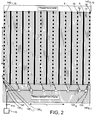
- Fig. 2 is a perspective top view of the bowling lanes of a bowling center illustrating one possible implementation of a preferred lighting system in accordance with the invention;
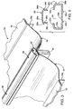
- Fig. 3 is a perspective view of a preferred division capping assembly in which light strings of the inventive lighting system may be mounted;
- Fig. 4 is a sectional elevational view of a portion of the division capping assembly shown in Fig. 3;
- Fig. 5 is a sectional elevational exploded view of the two preferred components of the division capping assembly shown in Fig. 3;
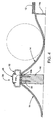
- Fig. 6 is a perspective view of a preferred light module that may be used in the inventive lighting system;
- Fig. 7 is an electrical diagram in block form of an exemplary light string and address module of the inventive lighting system;
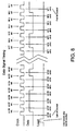
- Fig. 8 is a timing chart representing, by way of example only, the relative timings of the data, clock, and load signals that are transmitted by the inventive lighting system;
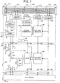
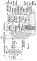
- Fig. 9 is an electrical diagram in block form of an exemplary central controller of the inventive lighting system; and
- Fig. 10 is an electrical diagram in block form of an alternative embodiment of the light modules in accordance with another preferred embodiment of the present invention.
-
- Fig. 1 shows an example of a
lighting system 100 constructed in accordance with an embodiment of the present invention. In general,lighting system 100 includes acentral controller 110, a plurality ofaddress modules 1201 through 120N coupled tocentral controller 110 by adata cable 115, and a plurality oflight strings 1301 through 130N, each associated with and coupled to one ofaddress modules 1201 through 120N. Eachlight string 130n includes a plurality oflight modules 140n,1 through 140n,M coupled together in a linear fashion. - As will be explained in more detail below,
central controller 110 may be coupled to an external device orsystem 150, such as the bowling center's bowling scoring system and/or may be coupled to anaudio system 160, such as a bowling center's music system. - Fig. 2 shows an example of how
lighting system 100 may be implemented in a bowling center. As shown in Fig. 2, a bowling center typically includes a plurality of parallel lane surfaces 12. Such lane surfaces are typically grouped into pairs so as to share a common ball return. Between the lanes associated with different lane pairs is adivision member 16. The preferred structure for adivision capping assembly 20 that is mounted ondivision member 16 is described below with reference to Figs. 3 through 5. It is within thedivision capping assemblies 20 that the light strings 30 are preferably run. As further explained below, the division capping assemblies have a transparent cover to allow light projecting from thelight modules 140 to be viewed by the bowlers and spectators. - As described above, each
light string 130 is coupled to anaddress module 1201 through 1208, which are coupled to acentral controller 110 via adata cable 115. The address modules may be mounted within the division capping assemblies, the bowling scoring consoles or anywhere else in proximity to one end of each light string. Conceivably, the address modules may be mounted behind the masking units and/or pinsetters.Central controller 110 may be disposed at the front desk of the bowling center, in a front office, or anywhere else in the bowling center. - As shown in Figs. 3-5, each
bowling lane 12 has alane surface 10 lying between a pair of lane-straddling gutters such that onegutter 14 of eachlane 12 is immediately adjacent the gutter of the next lane, with adivision member 16 therebetween. On the opposite side of each of the twolanes 12 depicted in Fig. 3 is the second gutter (not shown) which is adjacent the ball return, in conventional manner. - Preferably the
gutter elements 14 have anupstanding support leg 14aadjacent lane 12 and asupport flange 14b on the opposite edge of the gutter resting ondivision member 16.Flange 14b is interengaged with thelower member 22 ofassembly 20, with bothmember 22 and the gutters being secured todivision member 16 by threaded fasteners such as screws 30. -
Lower member 22 is preferably an elongated extrusion element which runs the length of the bowling lane, preferably in segments thereof. This lower member has a lower, i.e., bottom,wall 22a, a pair ofside walls 22b which extend integrally up fromlower wall 22a, and a pair ofupper flanges 22c which extend integrally from the upper ends ofwalls 22b generally toward each other but defining an openelongated channel 24 therebetween that serves as a convenient pathway for stringing the light strings 130. The side walls and flanges may be one continuous curve instead of extending upwardly and then inwardly. Protruding from the bottom oflower wall 22a are a pair ofprotrusion ribs 22d for engaging recess grooves in the respective adjacent edge portions ofgutters 14. Alternatively, the recess grooves can be inmember 22 and the protrusion ribs inflanges 22c. - The
upper cap member 26 ofassembly 20 comprises anupper wall 26a and a pair of spacedlegs 26b depending downwardly fromupper wall 26a. The cap may be in segments for easy handling and assembly. Thelegs 26b are spaced apart an amount about equal to the width ofspace 24, and have laterally outwardly offsetdetents 26c extending in opposite directions. The lower portions of these detents are sloped upwardly outwardly for engagement withflanges 22c whereby downward force applied to capmember 26causes legs 26b to be shifted inwardly byflanges 22c against the inherent bias of the legs untildetents 26c engage beneath the bottom surfaces offlanges 22c. The presently preferred polymer for the base member and the cap member is rigid polyvinylchloride (PVC) but could be a polyester or any other suitable polymer. The outer edges ofupper wall 26a ofcap 26 preferably have downwardly outwardly slopedtapered flanges 26d which are resiliently upwardly deformable slightly asdetents 26c snap beneathflanges 22c for tight securement.Cap member 26 is translucent or transparent such that output from spaced lights located within thehollow assembly 20 will be viewable along the length of the bowling lanes to provide highly colorful effects. Conceivably, the lower member can also be translucent or transparent. - By using the above-described construction for the
division capping assemblies 20,cap 26 may be readily removed and re-attached to allow the light strings to be easily strung along the length of the lane. Further, this division capping construction allows for quick access and replacement of the lighting modules. Although the light strings are described as being run within the division capping assemblies, the light strings may also be run on or within the ball return capping assemblies. - As shown in Fig. 6, each
light module 140 may be formed on acircuit board 30 and mounted in ahousing 40. Preferably,light module 140 includes a multi-color lighting device including three light emitting diodes (LEDs) or a single LED with multiple (3) colors as light sources. More preferably, these LEDs include ared LED 32, agreen LED 34, and ablue LED 36. By providing red, green, and blue LEDs, which are the primary additive colors, eachlight module 140 may be controlled to emit not only one of the red, green, or blue colors, but also to emit white, cyan, yellow, or magenta when combinations ofLEDs - To project the light from
LEDs portion 44 of the upper surface ofhousing 40 is sloped upward to define anopening 46 through which the light is projected. An inner surface ofportion 44 preferably has areflector 48 disposed thereon. In this manner,light modules 140 may be disposed withinchannel 24 so as to project the light back toward the approach area of the bowling lanes so as to appear more bright to the bowlers and spectators.Housing 40 may be provided with anaperture 42 defining aconnection port 35 from which connector pins 38 extend fromcircuit board 30. Connector pins 38 are provided to allow coupling to aplug 50 of awiring cable 125 which extends from the opposite end of the nextlight module 140. It will be appreciated thatport 35 may be configured as a female port having receptacles rather than a male port having pins 38. -
Light module housing 40 may also include a similar port at its opposite end for coupling to awiring cable 125 of anotherlight module 140 or may have thecable 125 more permanently mounted thereto. With aport 35 at one end and acable 125 with aplug 50 provided at an opposite end, such light modules may be serially coupled together to form a light string. It will be appreciated, however, thatwiring cables 125 may be permanently mounted to both ends oflight module 140 so as to have a plurality of suchlight modules 140 permanently strung together. However, such a permanent mounting may be less desirable if it should become necessary to replace any one light module within the light string. - Having described the physical components of this preferred embodiment of a lighting system in accordance with the present invention, the electrical and functional aspects of the inventive lighting system are described below with reference to Figs. 7 through 9. As shown in Fig. 7, each
address module 120 includes a pair ofcable connectors data cable 115. It will be appreciated by those skilled in the art thatconnectors 111 and/or 112 may be mounted within an address module housing or be mounted at the end of a cable extension so as to mate with the connector of an upstream or downstream address module. As shown in Fig. 7,cable 115 includespower supply lines 113 for providing power to each address module system,ground lines 114, and anearth ground line 116. Further,cable 115 includes twolines 117 upon which is transmitted a differentiated load signal, a second pair oflines 118 upon which is transmitted a differentiated data stream, and a third pair oflines 119 upon which is transmitted a differentiated clock signal. The load signal, data stream, and clock signal are described in more detail below. -
Address modules 120 also include aload line interface 122 coupled toline pair 117, adata line interface 123 coupled toline pair 118, and aclock line interface 124 coupled toline pair 119. Load, data, and clock line interfaces 122 through 124 receive the differentiated signals on the respective line pairs and generate a load signal, a data stream signal, and a clock signal, respectively. Preferably, these interfaces utilize an optical coupling so as to reduce the current drawn frombus 115. -
Address modules 120 further include afirst power converter 121a and a second power converter 121b.First power converter 121a is coupled to the ground and power lines ofcable 115 for supplying power to those portions ofinterfaces cable 115. Second power converter 121b is provided to convert power received from an external power supply and supply power tolight strings 130 and to those portions ofinterfaces cable 115. By using two power converters, the light strings may be isolated fromcable 115. - The data stream signal as output from
data line interface 123 is supplied to an 8-bit shift register 126. As the data stream signal is received byshift register 126, it is shifted throughshift register 126 in response to the clock signal output fromclock line interface 124. As data is shifted throughregister 126, it is passed along online 138 ofwiring cable 125 to thefirst light module 1401 of thelight string 130. This data is received by a 3-bit shift register 146, which shifts this data therethrough in response to the same clock signal to which 8-bit shift register 126 responds. As the data is shifted through 3-bit shift register 146, it is passed downstream to the 3-bit shift register of the next light module. When twentylight modules 140 are provided in a light string, the serially-connected 3-bit shift registers of each of thelight modules 140 and the 8-bit shift register 126 of the associatedaddress module 120, effectively operate as a 68-bit shift register. As such, new data may be loaded into the shift registers every 68 clock pulses. Thus, the first 60 bits of a data signal transmitted online pair 118 will correspond to twenty 3-bit data signals used as activation signals to control theLEDs bit shift register 126. - As shown in Fig. 8, for every 68-bit data signal that is clocked through 8-
bit shift register 126 and the twenty 3-bit shift registers 146 of a light string, a load signal is transmitted online pair 117. This load signal is supplied byload line interface 122 to an ANDgate 134. The other input of ANDgate 134 is coupled to the output of anaddress comparator 128 that compares the 8 bits that are stored in 8-bit shift register 126 at that time with an 8-bit address uniquely associated withaddress module 120. If the address in 8-bit shift register 126 corresponds to the unique address of theaddress module 120,address comparator 128 supplies a high logic level to ANDgate 134 thereby enabling ANDgate 134 to respond to the load signal by outputting the load signal online 136 ofwiring cable 125 to alatch circuit 148 of eachlight module 140.Latch circuit 148 is coupled between the 3-bit output of the 3-bit shift register 146 and three switching elements, such astransistors 152 through 156, which selectively activate arespective LED 32 through 36.Latch circuit 148 maintainsLEDs 32 through 36 in their current illuminated state until such time that a load signal is received online 136. When a load signal is received online 136,latch circuit 148 applies the 3-bit output from 3-bit shift register 146 toswitches LEDs bit shift register 146 at the time that the load signal was received online 136. - If, on the other hand, the
address comparator 128 determines that the 8 bits of data stored in 8-bit shift register 126 do not correspond to the unique 8-bit address ofaddress module 120,address comparator 128 outputs a low logic level signal to ANDgate 134 thereby preventing ANDgate 134 from transmitting the load signal online 136 when it is received fromload line interface 122. Thus, unless the last 8 bits of the 68-bit data stream correspond to the unique address of the address module, the light string will not respond to the previously-transmitted 60 bits of data that have been shifted into the 3-bit shift registers 146 oflight modules 1401 through 140m. As shown in Fig. 7, the unique address for the address modules may be selected using a plurality of DIP switches 132. Preferably, addresscomparator 128 also compares the 8-bit address stored inshift register 126 with a global address that is shared in common with all theaddress modules 120 of the lighting system. In this manner,central controller 110 may enable all the light strings to respond to a common data signal transmitted to all the light strings using one 68-bit data stream. - With the construction shown in Fig. 7, each LED of each light module of each light string may be independently controlled by
central controller 110. Thus,controller 110 may control when, and for how long, each light module emits light.Controller 110 may also control the color of the light that is emitted from each light module. With such flexibility,central controller 110 can create a virtually unlimited number of lighting patterns on the light strings. - Although the lighting system has been described as utilizing 20 light modules per string and utilizing 8 bits of the data stream for an address, it will be appreciated by those skilled in the art that the number of light modules per string may be arbitrarily increased or decreased and that the number of bits per address may be varied as a function of the number of address modules/light strings that are provided. Further, given that the
address modules 120 are daisy-chained together, an arbitrary number of such address modules may be connected into the system. Further, certain concepts embodied in the inventive lighting system may be implemented using more or less than three LEDs per module. - Having described the manner by which the address modules and light strings respond to the clock, data, and load signals transmitted by
central controller 110, the manner in whichcentral controller 110 selects which data to supply is described below with reference to Fig. 9. -
Central controller 110 preferably includes a central processing unit (CPU) 200, acode memory 202, adata memory 204, a memory I/Odecode logic circuit 206, a first output port (port 0) 208, a second output port (port 1) 210, aninput port 212, a multi-pointdata cable interface 214, a front panel switch interface 216,configuration dip switches 218, a frontpanel display interface 220, awatchdog timer 222, and anEEPROM 224. CPU orprocessor 200 controls all the functions and operations ofcentral controller 110. In general,processor 200 executes operating instructions stored incode memory 202 as received over adata bus 225 connected therebetween.Code memory 202 is preferably in the form of an EPROM.Code memory 202 also preferably stores numerous preprogrammed display patterns that may be read therefrom in any sequence in accordance with address signals received fromprocessor 200 via an address bus 227. When a preprogrammed display pattern is read fromcode memory 202, it is transmitted overdata bus 225 tofirst output port 208.First output port 208 creates the data stream that is transmitted to each of the addressable light strings via multi-pointdata cable interface 214 anddata cable 115.First output port 208 also transmits a periodic strobe signal towatchdog timer 222.Watchdog timer 222 is provided to transmit a reset signal toprocessor 200 whenever a strobe signal is not received fromfirst output port 208 within a predetermined time interval. In this manner,central controller 110 will not become locked up. - Memory I/O
decode logic circuit 206 is provided to map all memory and I/O address locations.Circuit 206 is coupled to receive address signals fromprocessor 200 ordata memory 204 via address bus 227 and to receive read and write commands fromprocessor 200. In response to information received at its inputs, decodelogic circuit 206 transmits control signals to first andsecond output ports data bus 225 through their respective output lines. Further, decodelogic circuit 206 may respond by sending a read signal to inputport 212 to cause it to read inputs from front panel switch interface 216 orconfiguration dip switches 218 and to transmit these inputs ondata bus 225 so that they may be received byprocessor 200. As will be explained further below, decodelogic circuit 206 further transmits read and write signals to an analog-to-digital (A/D)converter 240 of anaudio interface 228 to cause it to send or receive data ondata bus 225. - As shown in Fig. 9,
central controller 110 may further include anexternal device interface 226 to which an external device, such as the bowling center's bowling scoring system, may be connected. Preferably,interface 210 is a standard RS-232 Serial Port andprocessor 200 includes a UART so as to enable any conventional personal computer (PC) or server to be connected tocentral controller 110. By connecting the bowling scoring system toexternal device interface 226,processor 200 may receive prompts from the scoring system that identify a particular lane or lane pair, and an event that occurred at the identified lane. For example, the bowling scoring system may informcentral controller 110 that a strike has been rolled onlane 4. In such an event,central controller 110 could respond by transmitting data streams including the addresses for the two address modules on the adjacent borders oflane 4 so as to create a specific light show with respect to that lane. Thus, the light bordering that lane may be used to create a light show in synchronism with the exciter graphics shown on the scoring system displays. -
Central controller 110 may further include anaudio interface 228 which enablescentral controller 110 to interface with an audio device or system, such as the bowling center's audio system.Audio interface 228 preferably includes RCA input jacks 230 into which an audio line level signal may be received from the audio device or system. The line level signal is then split and applied to ahigh pass filter 232, aband pass filter 234, and alow pass filter 236.Filters analog switch 238, which is responsive to band select signals supplied fromprocessor 200 to select one or more of the separated frequency components to supply to the input of A/D converter 240. A/D converter 240 converts the amplitude of the selected frequency component of the input audio signal into an 8-bit digital value. This 8-bit digital value may be output ondata bus 225 and received byprocessor 200 when it receives a write-enable signal fromdecode logic circuit 206. - Through the operation of a switch on front panel switch interface 216 or the operation of a
configuration dip switch 218,processor 200 may be set in a music mode whereby it instructs decodelogic circuit 206 to enable A/D converter 240 to output a digital value representing the amplitude of a received audio signal ondata bus 225.Processor 200 receives this digitized amplitude level and responds by selecting a light display data pattern that may vary in some respect as a function of the digitized amplitude level of the input audio signal. Further, as noted above,processor 200 may select either the treble, midrange, or base frequency component of the input audio so as to change the lighting patterns in response to either the amplitude of the base, midrange, or treble component levels. Thus,processor 200 may control the light patterns generated by the light strings in synchronism with the music played on the bowling center's audio system.Processor 200 may be configured so as to generate a lighting pattern in which the light strings are illuminated to simulate a power meter of, for example, a graphic equalizer, or may control the different LEDs of each light module so as to change color in response to the component amplitude levels of the input audio signal. The specific manner by whichprocessor 200 responds to the input audio signal may be set by an operator through the actuation of a switch on front panel switch interface 216 or the operation of adip switch 218. It will be appreciated by those skilled in the art thatprocessor 200 may be programmed to respond to the input audio signal level to create virtually any sequence of lighting patterns in response to the characteristics of the input audio signal. It should further be noted thatprocessor 200 may dynamically vary the bid selection signal applied toanalog switch 238 so as to modulate the different lights in each module in response to different frequency components of the input audio signal. - Front
panel display interface 220 is preferably coupled to a display that is mounted in a location that may be viewed by the operator. By providing a display device, information, such as the operating mode, may be displayed to an operator. The information to be displayed on the display device may be transmitted from one of the memories orprocessor 200 overdata bus 225 tooutput port 210, which, in turn, transmits the display information to frontpanel display interface 220 when a write-enable signal is received fromdecode logic circuit 206. The display device may further be controlled directly byprocessor 200, which is directly coupled to frontpanel display interface 220. -
Data memory 204 is provided as a "scratch pad" memory forprocessor 200 and for storage of display patterns that may be downloaded viaexternal device interface 226 from an external device. In this manner, the various lighting patterns that may be displayed by the lighting system may be varied at any time after installation of the system in a bowling center.EEPROM 224 is a nonvolatile memory used to store semi-permanent system configuration data that is utilized byprocessor 200. - According to an alternative embodiment shown in Fig. 10, the number of colors of light that may be emitted from each light module may be significantly increased by providing a
variable gain amplifier 300 for eachLED light module 140 with 9-bit shift registers 302 so as to enable a 3-bit intensity level to be applied to eachvariable gain amplifier 300. In this manner, the intensity of the light emitted from each LED may be selectively controlled thereby enabling the saturation and hue of the light emitted from each light module to be controlled by the central controller. - Although the present invention has been described as being implemented in a bowling center, the light system could be employed in other locations or entertainment facilities. For example, the light modules could be embedded in a dance floor or the floor in a roller skating rink. Further, it should be noted that the light strings need not be arranged in parallel spaced lines, but instead may be laid out in a more serpentine fashion to form various shapes. Further, the light strings may be intertwined and intersect so long as the surface area on which they are mounted does not require that each light string is disposed in parallel spaced apart fashion as would be desired when mounting in the division caps of a bowling center. In this regard, it should also be noted that light strings may alternatively or additionally be mounted to the walls, masking unit, or ceiling of a bowling center. Such additional light strings could be controlled in synchronism by the same central controller used to control the lights in the division caps.
- Given the flexibility provided by lighting systems which are embodiments of the present invention, such lighting systems may be used to create graphic displays. For example, by arranging the light strings and light modules into a plurality of rows and columns (as would typically be the case when they are mounted in the division caps of a bowling center), a dynamic graphic display may be created through appropriate transmission of the data signals to the light modules. For example, the resulting two-dimensional array of light modules may be selectively illuminated in a dynamic fashion to display a game of PONG whereby the two outer light strings of the matrix are used to illuminate moving paddles and the remaining inner light strings may be used to create the illusion of a ball moving back and forth between the paddles. Moreover, given the ability of the lighting system to change the color of the light emitted from each light module, each light module may be viewed as a pixel of a wide-area graphic display. Such a wide-area graphic display may be used in virtually any location including placement on building exteriors and on billboards.
- The above description is considered that of the preferred embodiments only. Modifications of the invention will occur to those skilled in the art and to those who make or use the invention. Therefore, it is understood that the embodiments shown in the drawings and described above are merely for illustrative purposes and not intended to limit the scope of the invention, which is defined by the following claims as interpreted according to the principles of patent law, including the Doctrine of Equivalents.
Claims (30)
- A lighting system (100) for a bowling center having at least two bowling lanes, said lighting system comprising: a light string (130n) disposed along a divider separating said bowling lanes, said light string including a plurality of independently controllable light modules each emitting light in response to an activation signal uniquely associated with the light module; and a controller (110) coupled to said light string for generating and transmitting activation signals to said light modules to independently control said light modules.
- A system as claimed in claim 1, including a plurality of said light strings each disposed along different bowling lane dividers, and a plurality of address modules each coupled to one of said light strings and coupled to said controller, wherein said controller transmits activation signals to the light modules of a specific light string while transmitting therewith an address to which the address module associated with the specified light string will respond by enabling the light modules of the associated light string to respond to the activation signals transmitted from said controller.
- A system as claimed in claim 1 or claim 2, wherein said controller includes an interface for connecting to an external system, said controller being responsive to signals received from the external system for generating and transmitting activation signals to said light modules so as to create a selected lighting display pattern on said light string.
- A system as claimed in any preceding claim, wherein said controller includes an interface for connecting to an external system, said controller being responsive to signals received from the external system for generating and transmitting activation signals to said light modules so as to create a selected lighting pattern.
- A wide-area decorative lighting system (100) for a bowling center, said wide-area lighting system comprising: a plurality of light strings (130n) each including a plurality of independently controllable light modules that emit light in response to an activation signal uniquely associated with each light module; a plurality of address (120n) modules each associated with and coupled to one of said light strings; and a central controller (110) coupled to said plurality of address modules for generating and transmitting activation signals to said light modules to independently control said light modules, wherein said central controller transmits activation signals to the light modules of a specific light string while transmitting therewith an address to which the address module associated with the specified light string will respond by enabling the light modules of the associated light string to respond to the activation signals transmitted from said central controller.
- A system as claimed in claim 5, wherein said central controller includes an interface for connecting to an external system, said central controller being responsive to signals received from the external system for generating and transmitting activation signals to said light modules so as to create a selected graphic display pattern.
- A system as claimed in claim 5 or claim 6, wherein said central controller includes a memory for storing data representing a plurality of lighting patterns, said central controller selects one of the plurality of lighting patterns, reads the stored data representing the selected data pattern, and generates and transmits activation signals to said light modules in order to generate the selected light pattern on said plurality of light strings.
- A lighting system (100) for a bowling center having at least two bowling lanes, said lighting system comprising a light string (130n) disposed along a divider (16) separating said two bowling lanes, said light string including a plurality of light modules each including a multi-color lighting device (32,34,36) for emitting light having one of a plurality of selectable colors.
- A system as claimed in claim 8, wherein each of said light modules includes a red LED, a green LED, and a blue LED, said LEDs being independently activated in response to an activation signal.
- A system as claimed in claim 8 or claim 9, further including a controller coupled to said light string for generating and transmitting activation signals to said light modules to independently activate said light sources of said light modules.
- A wide-area graphic display system (100) comprising: a plurality of light strings (130n) each including a plurality of independently controllable light modules (140n) that emit light in response to an activation signal uniquely associated with each light module; a plurality of address modules (120n) each associated with and coupled to one of said light strings; and a central controller (110) coupled to said plurality of address modules for generating and transmitting activation signals to said light modules to independently control said light modules, wherein said central controller transmits activation signals to the light modules of a specific light string while transmitting therewith an address to which the address module associated with the specified light string will respond by enabling the light modules of the associated light string to respond to the activation signals transmitted from said central controller to thereby generate a graphic display.
- A system as claimed in any preceding claim, wherein each of said light modules include a red LED, a green LED, and a blue LED, said LEDs being separately controllable such that said central controller may separately select one of at least seven different colors to be emitted from each of said light modules by transmitting an activation signal to selected ones or combinations of said red, green, and blue LEDs.
- A system as claimed in any preceding claim, wherein said controller includes a memory for storing data representing a plurality of lighting patterns, said controller selects one of the plurality of lighting patterns, reads the stored data representing the selected data pattern, and generates and transmits activation signals to said light modules in order to generate the selected light pattern on said plurality of light strings.
- A system as claimed in any one of claims 5 to 13, wherein said plurality of light strings are physically mounted in parallel to one another.
- A system as claimed in any one of claims 5 to 13, wherein said plurality of light strings are mounted in a single plane.
- A system as claimed in any one of claims 5 to 13, wherein the light modules of a light string are coupled in series.
- A system as claimed in any preceding claim including a plurality of division capping assemblies, each mounted on a lane pair divider, each of said division capping assemblies defining a channel and having a transparent cover such that a light string may be run within said channel and the light from the light modules may be emitted through said transparent cover.
- A system as claimed in claim 2, claim 5, claim 8 or claim 11 or any claim dependent upon any of claims 2, 5, 8 and 11, wherein the address module and the light modules of an associated light string include a serially connected shift registers responsive to a clock signal transmitted from said central controller to receive a data stream also transmitted from said central controller; and preferably wherein said central controller transmits a load signal each time a data stream is transmitted, each said address module responds to the load signal by enabling the load signal to be transmitted to the associated light modules if the data stored in the shift register of the address module at the time the load signal is received corresponds to the unique address of the address module, whereby each of said light modules respond to said load signal by controlling the light emitted therefrom in accordance with the data stored in the shift register of the light module at the time the load signal is received.
- A bowling center lighting system (100) comprising: a plurality of addressable light strings (130n) each including a plurality of independently controllable light modules (140n) that emit light in response to an activation signal uniquely associated with each light module; and a controller (110) coupled to said addressable light strings and having a memory for storing data representing a plurality of lighting patterns, said controller selects one of the plurality of lighting patterns, reads the stored data representing the selected data pattern, and generates and transmits activation signals to said light modules in order to generate the selected light pattern on said plurality of light strings.
- A system as claimed in any preceding claim, wherein said controller includes an audio interface for connection of an output of an audio device, said controller generates and transmits activation signals to said light modules in order to generate a light pattern on said plurality of light strings that changes in appearance in response to changes in a characteristic of an audio signal received from the audio device.
- A system as claimed in any preceding claim, wherein each of said light modules includes a multi-color lighting device for emitting light of different colors such that said controller may select colors of the light to be emitted from each one of said light modules.
- A system as claimed in any preceding claim, wherein said controller includes an interface for connecting to a bowling scoring system, said controller being responsive to signals received from said bowling scoring system for generating and transmitting activation signals to said light modules so as to create a selected graphic display pattern; and preferably wherein said controller is responsive to a signal from the bowling scoring system that identifies a bowling lane and an event that occurred at the identified bowling lane by generating and transmitting activation signals to light modules associated with the identified bowling lane so as to generate a lighting display pattern for the identified bowling lane.
- A bowling center lighting system (100) comprising: a plurality of addressable light strings (130n) each including a plurality of independently controllable light modules that emit light in response to an activation signal uniquely associated with each light module; and a control circuit coupled to said addressable light strings and having an audio interface for connection an output of an audio device, said control circuit generates and transmits activation signals to said light modules in order to generate a light pattern on said plurality of light strings that changes in appearance in response to changes in a characteristic of an audio signal received from the audio device.
- A system as claimed in claim 23, wherein said control circuit includes an interface for connecting to a bowling scoring system, said control circuit being responsive to signals received from said howling scoring system for generating and transmitting activation signals to said light modules so as to create a selected graphic display pattern.
- A system as claimed in claim 23 or claim 24, wherein said control circuit includes a memory for storing data representing a plurality of lighting patterns, said control circuit selects one of the plurality of lighting patterns, reads the stored data representing the selected data pattern, and generates and transmits activation signals to said light modules in order to generate the selected light pattern on said plurality of light strings.
- A lighting system (100) for a bowling center having an automatic scoring system, said lighting system comprising: a plurality of addressable light strings each including a plurality of independently controllable light modules that emit light in response to an activation signal uniquely associated with each light module; and a control circuit coupled to said addressable light strings and having an interface for connection the automatic scoring system, wherein said control circuit is responsive to signals received from said automatic scoring system for generating and transmitting activation signals to said light modules so as to create a selected graphic display pattern
- A system as claimed in claim 26, wherein said control circuit is responsive to a signal from the automatic scoring system that identifies a bowling lane by creating a light show on the light strings bordering the identified lane.
- A system as claimed in claim 26 or claim 27, wherein said control circuit is responsive to a signal from the automatic scoring system that identifies a bowling lane and an event that occurred on the identified bowling lane by selecting a display pattern associated with the identified event creating a light show having the selected display pattern on the light strings bordering the identified lane.
- A system as claimed in claim 26 or claim 27 or claim 28, wherein said control circuit includes an audio interface for connection of an output of an audio device, said control circuit generates and transmits activation signals to said light modules in order to generate a light pattern on said plurality of light strings that changes in appearance in response to changes in a characteristic of an audio signal received from the audio device.
- A system as claimed in any one of claims 23 to 28, wherein each of said light modules includes a multi-color lighting device for emitting light of different colors such that said control circuit may select colors of the light to be emitted from each one of said light modules.
Applications Claiming Priority (2)
| Application Number | Priority Date | Filing Date | Title |
|---|---|---|---|
| US38449 | 1993-03-29 | ||
| US09/038,449 US6031343A (en) | 1998-03-11 | 1998-03-11 | Bowling center lighting system |
Publications (2)
| Publication Number | Publication Date |
|---|---|
| EP0942631A2 true EP0942631A2 (en) | 1999-09-15 |
| EP0942631A3 EP0942631A3 (en) | 2001-04-25 |
Family
ID=21900024
Family Applications (1)
| Application Number | Title | Priority Date | Filing Date |
|---|---|---|---|
| EP99301842A Withdrawn EP0942631A3 (en) | 1998-03-11 | 1999-03-11 | Bowling center lighting system |
Country Status (3)
| Country | Link |
|---|---|
| US (1) | US6031343A (en) |
| EP (1) | EP0942631A3 (en) |
| JP (1) | JPH11317296A (en) |
Cited By (17)
| Publication number | Priority date | Publication date | Assignee | Title |
|---|---|---|---|---|
| WO2001099475A1 (en) | 2000-06-21 | 2001-12-27 | Color Kinetics Incorporated | Method and apparatus for controlling a lighting system in response to an audio input |
| US6717376B2 (en) | 1997-08-26 | 2004-04-06 | Color Kinetics, Incorporated | Automotive information systems |
| US6774584B2 (en) | 1997-08-26 | 2004-08-10 | Color Kinetics, Incorporated | Methods and apparatus for sensor responsive illumination of liquids |
| US6777891B2 (en) | 1997-08-26 | 2004-08-17 | Color Kinetics, Incorporated | Methods and apparatus for controlling devices in a networked lighting system |
| US6781329B2 (en) | 1997-08-26 | 2004-08-24 | Color Kinetics Incorporated | Methods and apparatus for illumination of liquids |
| US6801003B2 (en) | 2001-03-13 | 2004-10-05 | Color Kinetics, Incorporated | Systems and methods for synchronizing lighting effects |
| NL2000926C2 (en) * | 2007-10-12 | 2009-04-15 | Jan Jonquiere | Light and sound column. |
| US7652436B2 (en) | 2000-09-27 | 2010-01-26 | Philips Solid-State Lighting Solutions, Inc. | Methods and systems for illuminating household products |
| US7659674B2 (en) | 1997-08-26 | 2010-02-09 | Philips Solid-State Lighting Solutions, Inc. | Wireless lighting control methods and apparatus |
| BE1018214A3 (en) * | 2008-01-02 | 2010-07-06 | Macroblock Inc | METHOD FOR MULTI-POINT OPERATION OF A CONTROL SYSTEM. |
| US7764026B2 (en) | 1997-12-17 | 2010-07-27 | Philips Solid-State Lighting Solutions, Inc. | Systems and methods for digital entertainment |
| US7845823B2 (en) | 1997-08-26 | 2010-12-07 | Philips Solid-State Lighting Solutions, Inc. | Controlled lighting methods and apparatus |
| US7959320B2 (en) | 1999-11-18 | 2011-06-14 | Philips Solid-State Lighting Solutions, Inc. | Methods and apparatus for generating and modulating white light illumination conditions |
| US8207821B2 (en) | 2003-05-05 | 2012-06-26 | Philips Solid-State Lighting Solutions, Inc. | Lighting methods and systems |
| US9955541B2 (en) | 2000-08-07 | 2018-04-24 | Philips Lighting Holding B.V. | Universal lighting network methods and systems |
| US10321528B2 (en) | 2007-10-26 | 2019-06-11 | Philips Lighting Holding B.V. | Targeted content delivery using outdoor lighting networks (OLNs) |
| CN113966055A (en) * | 2020-01-17 | 2022-01-21 | 新嘉数码电子(深圳)有限公司 | Method for controlling lamp string by power carrier, electronic billboard and device |
Families Citing this family (105)
| Publication number | Priority date | Publication date | Assignee | Title |
|---|---|---|---|---|
| US7187141B2 (en) * | 1997-08-26 | 2007-03-06 | Color Kinetics Incorporated | Methods and apparatus for illumination of liquids |
| US6806659B1 (en) * | 1997-08-26 | 2004-10-19 | Color Kinetics, Incorporated | Multicolored LED lighting method and apparatus |
| US7427840B2 (en) * | 1997-08-26 | 2008-09-23 | Philips Solid-State Lighting Solutions, Inc. | Methods and apparatus for controlling illumination |
| US7482764B2 (en) * | 1997-08-26 | 2009-01-27 | Philips Solid-State Lighting Solutions, Inc. | Light sources for illumination of liquids |
| US7353071B2 (en) * | 1999-07-14 | 2008-04-01 | Philips Solid-State Lighting Solutions, Inc. | Method and apparatus for authoring and playing back lighting sequences |
| US6975079B2 (en) * | 1997-08-26 | 2005-12-13 | Color Kinetics Incorporated | Systems and methods for controlling illumination sources |
| US6897624B2 (en) * | 1997-08-26 | 2005-05-24 | Color Kinetics, Incorporated | Packaged information systems |
| US6608453B2 (en) | 1997-08-26 | 2003-08-19 | Color Kinetics Incorporated | Methods and apparatus for controlling devices in a networked lighting system |
| US7014336B1 (en) * | 1999-11-18 | 2006-03-21 | Color Kinetics Incorporated | Systems and methods for generating and modulating illumination conditions |
| US7038398B1 (en) * | 1997-08-26 | 2006-05-02 | Color Kinetics, Incorporated | Kinetic illumination system and methods |
| US6965205B2 (en) * | 1997-08-26 | 2005-11-15 | Color Kinetics Incorporated | Light emitting diode based products |
| US6624597B2 (en) | 1997-08-26 | 2003-09-23 | Color Kinetics, Inc. | Systems and methods for providing illumination in machine vision systems |
| US7139617B1 (en) * | 1999-07-14 | 2006-11-21 | Color Kinetics Incorporated | Systems and methods for authoring lighting sequences |
| US7064498B2 (en) * | 1997-08-26 | 2006-06-20 | Color Kinetics Incorporated | Light-emitting diode based products |
| US6412024B1 (en) * | 1998-08-17 | 2002-06-25 | Sigma Designs, Inc. | Sound board emulation using digital signal processor |
| US6369524B2 (en) * | 1999-02-26 | 2002-04-09 | Maf Technologies Corp. | Addressable light dimmer and addressing system |
| US6169376B1 (en) * | 1999-05-10 | 2001-01-02 | Maf Technologies Corp. | Gas discharge tube changeable color display and digital controller system |
| US20040085781A1 (en) * | 2002-04-05 | 2004-05-06 | Bruce Wesson | LED products: flashing LED display and decorative LEDs for autos and trucks |
| US20080140231A1 (en) * | 1999-07-14 | 2008-06-12 | Philips Solid-State Lighting Solutions, Inc. | Methods and apparatus for authoring and playing back lighting sequences |
| JP2003510856A (en) * | 1999-09-29 | 2003-03-18 | カラー・キネティックス・インコーポレーテッド | Combined illumination and calibration apparatus and calibration method for multiple LEDs |
| US6357889B1 (en) | 1999-12-01 | 2002-03-19 | General Electric Company | Color tunable light source |
| US7049761B2 (en) | 2000-02-11 | 2006-05-23 | Altair Engineering, Inc. | Light tube and power supply circuit |
| US7550935B2 (en) * | 2000-04-24 | 2009-06-23 | Philips Solid-State Lighting Solutions, Inc | Methods and apparatus for downloading lighting programs |
| US7107712B2 (en) | 2000-06-06 | 2006-09-19 | Christine Ann Mueller | Lighting system |
| US20050275626A1 (en) * | 2000-06-21 | 2005-12-15 | Color Kinetics Incorporated | Entertainment lighting system |
| US7202613B2 (en) * | 2001-05-30 | 2007-04-10 | Color Kinetics Incorporated | Controlled lighting methods and apparatus |
| US7031920B2 (en) * | 2000-07-27 | 2006-04-18 | Color Kinetics Incorporated | Lighting control using speech recognition |
| US7042172B2 (en) * | 2000-09-01 | 2006-05-09 | Color Kinetics Incorporated | Systems and methods for providing illumination in machine vision systems |
| US6960892B2 (en) * | 2000-12-01 | 2005-11-01 | Loughrey James F | Variable output single constant source light fixture |
| US7038399B2 (en) * | 2001-03-13 | 2006-05-02 | Color Kinetics Incorporated | Methods and apparatus for providing power to lighting devices |
| US7462103B2 (en) * | 2001-03-22 | 2008-12-09 | Igt | Gaming system for individual control of access to many devices with few wires |
| AUPR725301A0 (en) * | 2001-08-24 | 2001-09-20 | Jones, Darryl John | Lighting apparatus |
| US7358679B2 (en) * | 2002-05-09 | 2008-04-15 | Philips Solid-State Lighting Solutions, Inc. | Dimmable LED-based MR16 lighting apparatus and methods |
| US7023543B2 (en) * | 2002-08-01 | 2006-04-04 | Cunningham David W | Method for controlling the luminous flux spectrum of a lighting fixture |
| ATE455451T1 (en) * | 2002-08-28 | 2010-01-15 | Philips Solid State Lighting | METHODS AND SYSTEMS FOR LIGHTING ENVIRONMENTS |
| US7300192B2 (en) * | 2002-10-03 | 2007-11-27 | Color Kinetics Incorporated | Methods and apparatus for illuminating environments |
| US20040141321A1 (en) * | 2002-11-20 | 2004-07-22 | Color Kinetics, Incorporated | Lighting and other perceivable effects for toys and other consumer products |
| TW200500926A (en) * | 2003-06-17 | 2005-01-01 | Darfon Electronics Corp | Light emitting module and keyboard using the same |
| WO2005004040A1 (en) * | 2003-07-02 | 2005-01-13 | Celartem Technology Inc. | Image sharpening with region edge sharpness correction |
| DE10342595A1 (en) * | 2003-09-15 | 2005-04-14 | Simon Hansel | Light module for big events |
| US7025687B2 (en) * | 2003-11-06 | 2006-04-11 | Brunswick Bowling & Billiards Corporation | Bowling center control system |
| DE602004026908D1 (en) * | 2003-11-20 | 2010-06-10 | Philips Solid State Lighting | LIGHT SYSTEM ADMINISTRATOR |
| EP1729615B1 (en) * | 2004-03-02 | 2019-05-08 | Signify North America Corporation | Entertainment lighting system |
| US7354172B2 (en) * | 2004-03-15 | 2008-04-08 | Philips Solid-State Lighting Solutions, Inc. | Methods and apparatus for controlled lighting based on a reference gamut |
| US7264552B2 (en) * | 2004-06-23 | 2007-09-04 | Rong Chen | Moveable gutter for bowling lanes having illumination sources |
| US7227075B2 (en) * | 2004-08-06 | 2007-06-05 | Henry Chang | Lighting controller |
| TW200811811A (en) * | 2006-08-16 | 2008-03-01 | Dynascan Technology Corp | Method for processing display signals of light emitting module string and display system thereof |
| US7708647B2 (en) * | 2007-06-18 | 2010-05-04 | Connell Ronald B | LED light and sound system for bowling pin deck |
| US8400061B2 (en) * | 2007-07-17 | 2013-03-19 | I/O Controls Corporation | Control network for LED-based lighting system in a transit vehicle |
| US8118447B2 (en) | 2007-12-20 | 2012-02-21 | Altair Engineering, Inc. | LED lighting apparatus with swivel connection |
| US7712918B2 (en) | 2007-12-21 | 2010-05-11 | Altair Engineering , Inc. | Light distribution using a light emitting diode assembly |
| US8360599B2 (en) | 2008-05-23 | 2013-01-29 | Ilumisys, Inc. | Electric shock resistant L.E.D. based light |
| US7976196B2 (en) | 2008-07-09 | 2011-07-12 | Altair Engineering, Inc. | Method of forming LED-based light and resulting LED-based light |
| US7946729B2 (en) | 2008-07-31 | 2011-05-24 | Altair Engineering, Inc. | Fluorescent tube replacement having longitudinally oriented LEDs |
| US8674626B2 (en) | 2008-09-02 | 2014-03-18 | Ilumisys, Inc. | LED lamp failure alerting system |
| US8256924B2 (en) | 2008-09-15 | 2012-09-04 | Ilumisys, Inc. | LED-based light having rapidly oscillating LEDs |
| US8653984B2 (en) | 2008-10-24 | 2014-02-18 | Ilumisys, Inc. | Integration of LED lighting control with emergency notification systems |
| US8214084B2 (en) | 2008-10-24 | 2012-07-03 | Ilumisys, Inc. | Integration of LED lighting with building controls |
| US7938562B2 (en) | 2008-10-24 | 2011-05-10 | Altair Engineering, Inc. | Lighting including integral communication apparatus |
| US8324817B2 (en) | 2008-10-24 | 2012-12-04 | Ilumisys, Inc. | Light and light sensor |
| US8444292B2 (en) | 2008-10-24 | 2013-05-21 | Ilumisys, Inc. | End cap substitute for LED-based tube replacement light |
| US8901823B2 (en) | 2008-10-24 | 2014-12-02 | Ilumisys, Inc. | Light and light sensor |
| US20110093493A1 (en) | 2008-10-28 | 2011-04-21 | Honeywell International Inc. | Building management system site categories |
| US8556452B2 (en) | 2009-01-15 | 2013-10-15 | Ilumisys, Inc. | LED lens |
| US8362710B2 (en) | 2009-01-21 | 2013-01-29 | Ilumisys, Inc. | Direct AC-to-DC converter for passive component minimization and universal operation of LED arrays |
| US8664880B2 (en) | 2009-01-21 | 2014-03-04 | Ilumisys, Inc. | Ballast/line detection circuit for fluorescent replacement lamps |
| US8435128B2 (en) | 2009-02-03 | 2013-05-07 | Brunswick Bowling & Billards Corporation | Bowling lane with mural image |
| US8330381B2 (en) | 2009-05-14 | 2012-12-11 | Ilumisys, Inc. | Electronic circuit for DC conversion of fluorescent lighting ballast |
| US8299695B2 (en) | 2009-06-02 | 2012-10-30 | Ilumisys, Inc. | Screw-in LED bulb comprising a base having outwardly projecting nodes |
| EP2446715A4 (en) | 2009-06-23 | 2013-09-11 | Ilumisys Inc | Illumination device including leds and a switching power control system |
| US20110196539A1 (en) * | 2010-02-10 | 2011-08-11 | Honeywell International Inc. | Multi-site controller batch update system |
| CA2792940A1 (en) | 2010-03-26 | 2011-09-19 | Ilumisys, Inc. | Led light with thermoelectric generator |
| WO2011119907A2 (en) | 2010-03-26 | 2011-09-29 | Altair Engineering, Inc. | Led light tube with dual sided light distribution |
| US8540401B2 (en) * | 2010-03-26 | 2013-09-24 | Ilumisys, Inc. | LED bulb with internal heat dissipating structures |
| US8454193B2 (en) | 2010-07-08 | 2013-06-04 | Ilumisys, Inc. | Independent modules for LED fluorescent light tube replacement |
| EP2593714A2 (en) | 2010-07-12 | 2013-05-22 | iLumisys, Inc. | Circuit board mount for led light tube |
| WO2012058556A2 (en) | 2010-10-29 | 2012-05-03 | Altair Engineering, Inc. | Mechanisms for reducing risk of shock during installation of light tube |
| US8870415B2 (en) | 2010-12-09 | 2014-10-28 | Ilumisys, Inc. | LED fluorescent tube replacement light with reduced shock hazard |
| JP5791392B2 (en) * | 2011-06-30 | 2015-10-07 | 輝雄 岡田 | LIGHTING DEVICE AND LIGHTING METHOD |
| WO2013028965A2 (en) | 2011-08-24 | 2013-02-28 | Ilumisys, Inc. | Circuit board mount for led light |
| US9223839B2 (en) | 2012-02-22 | 2015-12-29 | Honeywell International Inc. | Supervisor history view wizard |
| WO2013131002A1 (en) | 2012-03-02 | 2013-09-06 | Ilumisys, Inc. | Electrical connector header for an led-based light |
| US20130324272A1 (en) * | 2012-05-29 | 2013-12-05 | Qubica Europe S.P.A. | Interaction of video projection and effects lighting with bowling scoring system and methods of use |
| WO2014008463A1 (en) | 2012-07-06 | 2014-01-09 | Ilumisys, Inc. | Power supply assembly for led-based light tube |
| US9271367B2 (en) | 2012-07-09 | 2016-02-23 | Ilumisys, Inc. | System and method for controlling operation of an LED-based light |
| US9529349B2 (en) | 2012-10-22 | 2016-12-27 | Honeywell International Inc. | Supervisor user management system |
| US20150305103A1 (en) * | 2012-11-05 | 2015-10-22 | Osram Sylvania Inc. | Driver for solid state light sources |
| US9285084B2 (en) | 2013-03-14 | 2016-03-15 | Ilumisys, Inc. | Diffusers for LED-based lights |
| CN103268751B (en) * | 2013-05-09 | 2015-10-21 | 深圳市明微电子股份有限公司 | A kind of geocoding wiring method of LED display and system |
| US9267650B2 (en) | 2013-10-09 | 2016-02-23 | Ilumisys, Inc. | Lens for an LED-based light |
| US9971977B2 (en) | 2013-10-21 | 2018-05-15 | Honeywell International Inc. | Opus enterprise report system |
| EP3097748A1 (en) | 2014-01-22 | 2016-11-30 | iLumisys, Inc. | Led-based light with addressed leds |
| US11679322B2 (en) | 2014-04-21 | 2023-06-20 | Dfx: Sound Vision | Interaction of audio, video, effects and architectural lighting with bowling scoring system and methods of use |
| US9510400B2 (en) | 2014-05-13 | 2016-11-29 | Ilumisys, Inc. | User input systems for an LED-based light |
| US9933762B2 (en) | 2014-07-09 | 2018-04-03 | Honeywell International Inc. | Multisite version and upgrade management system |
| US9629229B2 (en) * | 2014-07-21 | 2017-04-18 | J. Kinderman & Sons, Inc. | Connectable and synchronizable light strings |
| EP3002995A1 (en) * | 2014-10-01 | 2016-04-06 | Koninklijke Philips N.V. | Lighting device |
| US11925853B1 (en) * | 2014-12-16 | 2024-03-12 | Qubicaamf Europe S.P.A. | Bowling game, related systems and methods of playing |
| US10161568B2 (en) | 2015-06-01 | 2018-12-25 | Ilumisys, Inc. | LED-based light with canted outer walls |
| US10362104B2 (en) | 2015-09-23 | 2019-07-23 | Honeywell International Inc. | Data manager |
| US10209689B2 (en) | 2015-09-23 | 2019-02-19 | Honeywell International Inc. | Supervisor history service import manager |
| US9942969B1 (en) * | 2016-09-29 | 2018-04-10 | Spx Corporation | Obstructions lighting system and process having operating modes |
| EP3393205A1 (en) * | 2017-04-21 | 2018-10-24 | Infineon Technologies AG | Synchronization for light-source driver circuitry |
| IT201700078353A1 (en) * | 2017-07-12 | 2019-01-12 | Qubicaamf Europe S P A | BOWLING PLANT. |
| US10888765B2 (en) * | 2018-09-19 | 2021-01-12 | Bradley N. Duke | Bowling ball ramp including embedded lighting and/or sound |
Citations (9)
| Publication number | Priority date | Publication date | Assignee | Title |
|---|---|---|---|---|
| US4887074A (en) * | 1988-01-20 | 1989-12-12 | Michael Simon | Light-emitting diode display system |
| US5008595A (en) * | 1985-12-18 | 1991-04-16 | Laser Link, Inc. | Ornamental light display apparatus |
| EP0534710A1 (en) * | 1991-09-26 | 1993-03-31 | Vari-Lite, Inc. | Computer controlled lighting system with intelligent data distribution networks |
| US5225765A (en) * | 1984-08-15 | 1993-07-06 | Michael Callahan | Inductorless controlled transition and other light dimmers |
| US5402702A (en) * | 1992-07-14 | 1995-04-04 | Jalco Co., Ltd. | Trigger circuit unit for operating light emitting members such as leds or motors for use in personal ornament or toy in synchronization with music |
| US5410328A (en) * | 1994-03-28 | 1995-04-25 | Trans-Lux Corporation | Replaceable intelligent pixel module for large-scale LED displays |
| US5420482A (en) * | 1993-02-11 | 1995-05-30 | Phares; Louis A. | Controlled lighting system |
| US5599236A (en) * | 1992-07-31 | 1997-02-04 | File; Jon P. | Bumper bowling system |
| GB2308535A (en) * | 1995-12-18 | 1997-06-25 | Te Heng Chung | Audio-visual-colourful multimedia system for bowling alleys |
Family Cites Families (6)
| Publication number | Priority date | Publication date | Assignee | Title |
|---|---|---|---|---|
| US3301558A (en) * | 1964-02-03 | 1967-01-31 | American Mach & Foundry | Selectively actuated ball path indicator |
| US4302010A (en) * | 1977-01-31 | 1981-11-24 | Amf Incorporated | Electronic bowling scoring system with video communication interface between manager console and lane score consoles |
| US5241379A (en) * | 1992-04-09 | 1993-08-31 | Telesystems Co., Ltd. | Automatic bowling scoring system |
| US5489241A (en) * | 1994-07-21 | 1996-02-06 | Brunswick Bowling & Billiards Corp. | Ultraviolet light illuminated bowling game |
| US5800274A (en) * | 1996-09-20 | 1998-09-01 | Amf Bowling, Inc. | Bowling alley bumper system for producing visual effects |
| US5713798A (en) * | 1997-01-30 | 1998-02-03 | Brodie, Jr.; Cary | Bowler's training device |
-
1998
- 1998-03-11 US US09/038,449 patent/US6031343A/en not_active Expired - Lifetime
-
1999
- 1999-03-09 JP JP11061536A patent/JPH11317296A/en active Pending
- 1999-03-11 EP EP99301842A patent/EP0942631A3/en not_active Withdrawn
Patent Citations (9)
| Publication number | Priority date | Publication date | Assignee | Title |
|---|---|---|---|---|
| US5225765A (en) * | 1984-08-15 | 1993-07-06 | Michael Callahan | Inductorless controlled transition and other light dimmers |
| US5008595A (en) * | 1985-12-18 | 1991-04-16 | Laser Link, Inc. | Ornamental light display apparatus |
| US4887074A (en) * | 1988-01-20 | 1989-12-12 | Michael Simon | Light-emitting diode display system |
| EP0534710A1 (en) * | 1991-09-26 | 1993-03-31 | Vari-Lite, Inc. | Computer controlled lighting system with intelligent data distribution networks |
| US5402702A (en) * | 1992-07-14 | 1995-04-04 | Jalco Co., Ltd. | Trigger circuit unit for operating light emitting members such as leds or motors for use in personal ornament or toy in synchronization with music |
| US5599236A (en) * | 1992-07-31 | 1997-02-04 | File; Jon P. | Bumper bowling system |
| US5420482A (en) * | 1993-02-11 | 1995-05-30 | Phares; Louis A. | Controlled lighting system |
| US5410328A (en) * | 1994-03-28 | 1995-04-25 | Trans-Lux Corporation | Replaceable intelligent pixel module for large-scale LED displays |
| GB2308535A (en) * | 1995-12-18 | 1997-06-25 | Te Heng Chung | Audio-visual-colourful multimedia system for bowling alleys |
Cited By (19)
| Publication number | Priority date | Publication date | Assignee | Title |
|---|---|---|---|---|
| US7659674B2 (en) | 1997-08-26 | 2010-02-09 | Philips Solid-State Lighting Solutions, Inc. | Wireless lighting control methods and apparatus |
| US6717376B2 (en) | 1997-08-26 | 2004-04-06 | Color Kinetics, Incorporated | Automotive information systems |
| US6774584B2 (en) | 1997-08-26 | 2004-08-10 | Color Kinetics, Incorporated | Methods and apparatus for sensor responsive illumination of liquids |
| US6777891B2 (en) | 1997-08-26 | 2004-08-17 | Color Kinetics, Incorporated | Methods and apparatus for controlling devices in a networked lighting system |
| US6781329B2 (en) | 1997-08-26 | 2004-08-24 | Color Kinetics Incorporated | Methods and apparatus for illumination of liquids |
| US7845823B2 (en) | 1997-08-26 | 2010-12-07 | Philips Solid-State Lighting Solutions, Inc. | Controlled lighting methods and apparatus |
| US7764026B2 (en) | 1997-12-17 | 2010-07-27 | Philips Solid-State Lighting Solutions, Inc. | Systems and methods for digital entertainment |
| US7959320B2 (en) | 1999-11-18 | 2011-06-14 | Philips Solid-State Lighting Solutions, Inc. | Methods and apparatus for generating and modulating white light illumination conditions |
| US7228190B2 (en) | 2000-06-21 | 2007-06-05 | Color Kinetics Incorporated | Method and apparatus for controlling a lighting system in response to an audio input |
| WO2001099475A1 (en) | 2000-06-21 | 2001-12-27 | Color Kinetics Incorporated | Method and apparatus for controlling a lighting system in response to an audio input |
| US9955541B2 (en) | 2000-08-07 | 2018-04-24 | Philips Lighting Holding B.V. | Universal lighting network methods and systems |
| US7652436B2 (en) | 2000-09-27 | 2010-01-26 | Philips Solid-State Lighting Solutions, Inc. | Methods and systems for illuminating household products |
| US6801003B2 (en) | 2001-03-13 | 2004-10-05 | Color Kinetics, Incorporated | Systems and methods for synchronizing lighting effects |
| US8207821B2 (en) | 2003-05-05 | 2012-06-26 | Philips Solid-State Lighting Solutions, Inc. | Lighting methods and systems |
| NL2000926C2 (en) * | 2007-10-12 | 2009-04-15 | Jan Jonquiere | Light and sound column. |
| WO2009048333A1 (en) * | 2007-10-12 | 2009-04-16 | JONQUIÈRE, Jan | Light and sound column |
| US10321528B2 (en) | 2007-10-26 | 2019-06-11 | Philips Lighting Holding B.V. | Targeted content delivery using outdoor lighting networks (OLNs) |
| BE1018214A3 (en) * | 2008-01-02 | 2010-07-06 | Macroblock Inc | METHOD FOR MULTI-POINT OPERATION OF A CONTROL SYSTEM. |
| CN113966055A (en) * | 2020-01-17 | 2022-01-21 | 新嘉数码电子(深圳)有限公司 | Method for controlling lamp string by power carrier, electronic billboard and device |
Also Published As
| Publication number | Publication date |
|---|---|
| JPH11317296A (en) | 1999-11-16 |
| EP0942631A3 (en) | 2001-04-25 |
| US6031343A (en) | 2000-02-29 |
Similar Documents
| Publication | Publication Date | Title |
|---|---|---|
| US6031343A (en) | Bowling center lighting system | |
| EP1620843B1 (en) | Tile lighting methods and systems | |
| US4358754A (en) | Sound-actuated advertising light display | |
| US7550931B2 (en) | Controlled lighting methods and apparatus | |
| JP5189184B2 (en) | Display device | |
| US10194503B2 (en) | Composite light source systems and methods | |
| US20040066148A1 (en) | Decorative lights with at least one commonly controlled set of color-controllable multi-color LEDs for selectable holiday color schemes | |
| US20070173320A1 (en) | Video game controller with illuminated cable | |
| EP2203032A2 (en) | Controlled lighting methods and apparatus | |
| US20070195526A1 (en) | Wireless lighting control methods and apparatus | |
| US5577831A (en) | Light-emitting structure of a decorative toy | |
| CN109348568B (en) | Multipurpose landscape brightening LED lighting equipment and customization system and method thereof | |
| US20050152128A1 (en) | Switch plate lens assembly | |
| KR20030009179A (en) | A convertible illuminated display case | |
| EP1790796B1 (en) | System for signalling and/or decorative lighting on technical floors | |
| US6779904B1 (en) | Title rack lighting for jukebox | |
| CN101154328B (en) | Screen display with sound lamps | |
| ES2407466T3 (en) | Light module for large events | |
| JP2001306013A (en) | Illumination device | |
| KR100929164B1 (en) | LED display board and communication method through communication convergence | |
| CN208269014U (en) | A kind of ceiling atmosphere lamp | |
| KR20210009962A (en) | LED Lighting System for Embodying Media Facade | |
| GB2405461A (en) | Lighting panel producing multi-coloured lighting effects | |
| KR20200068532A (en) | Lighting device | |
| CN211531371U (en) | Illumination and display control system |
Legal Events
| Date | Code | Title | Description |
|---|---|---|---|
| PUAI | Public reference made under article 153(3) epc to a published international application that has entered the european phase |
Free format text: ORIGINAL CODE: 0009012 |
|
| AK | Designated contracting states |
Kind code of ref document: A2 Designated state(s): AT BE CH CY DE DK ES FI FR GB GR IE IT LI LU MC NL PT SE |
|
| AX | Request for extension of the european patent |
Free format text: AL;LT;LV;MK;RO;SI |
|
| PUAL | Search report despatched |
Free format text: ORIGINAL CODE: 0009013 |
|
| AK | Designated contracting states |
Kind code of ref document: A3 Designated state(s): AT BE CH CY DE DK ES FI FR GB GR IE IT LI LU MC NL PT SE |
|
| AX | Request for extension of the european patent |
Free format text: AL;LT;LV;MK;RO;SI |
|
| RIC1 | Information provided on ipc code assigned before grant |
Free format text: 7H 05B 37/02 A, 7A 63D 1/00 B, 7H 05B 33/08 B, 7A 63J 17/00 B |
|
| AKX | Designation fees paid | ||
| REG | Reference to a national code |
Ref country code: DE Ref legal event code: 8566 |
|
| STAA | Information on the status of an ep patent application or granted ep patent |
Free format text: STATUS: THE APPLICATION IS DEEMED TO BE WITHDRAWN |
|
| 18D | Application deemed to be withdrawn |
Effective date: 20011026 |