EP0946045A2 - Camera with combination four-way directional and mode control interface - Google Patents
Camera with combination four-way directional and mode control interface Download PDFInfo
- Publication number
- EP0946045A2 EP0946045A2 EP99200766A EP99200766A EP0946045A2 EP 0946045 A2 EP0946045 A2 EP 0946045A2 EP 99200766 A EP99200766 A EP 99200766A EP 99200766 A EP99200766 A EP 99200766A EP 0946045 A2 EP0946045 A2 EP 0946045A2
- Authority
- EP
- European Patent Office
- Prior art keywords
- camera
- graphical elements
- mode
- user
- image
- Prior art date
- Legal status (The legal status is an assumption and is not a legal conclusion. Google has not performed a legal analysis and makes no representation as to the accuracy of the status listed.)
- Withdrawn
Links
Images
Classifications
-
- H—ELECTRICITY
- H04—ELECTRIC COMMUNICATION TECHNIQUE
- H04N—PICTORIAL COMMUNICATION, e.g. TELEVISION
- H04N1/00—Scanning, transmission or reproduction of documents or the like, e.g. facsimile transmission; Details thereof
- H04N1/0035—User-machine interface; Control console
- H04N1/00352—Input means
- H04N1/00397—Switches, knobs or the like
-
- H—ELECTRICITY
- H04—ELECTRIC COMMUNICATION TECHNIQUE
- H04N—PICTORIAL COMMUNICATION, e.g. TELEVISION
- H04N1/00—Scanning, transmission or reproduction of documents or the like, e.g. facsimile transmission; Details thereof
- H04N1/0035—User-machine interface; Control console
- H04N1/00405—Output means
- H04N1/00408—Display of information to the user, e.g. menus
- H04N1/00413—Display of information to the user, e.g. menus using menus, i.e. presenting the user with a plurality of selectable options
- H04N1/00416—Multi-level menus
- H04N1/00419—Arrangements for navigating between pages or parts of the menu
- H04N1/00424—Arrangements for navigating between pages or parts of the menu using a list of graphical elements, e.g. icons or icon bar
-
- H—ELECTRICITY
- H04—ELECTRIC COMMUNICATION TECHNIQUE
- H04N—PICTORIAL COMMUNICATION, e.g. TELEVISION
- H04N1/00—Scanning, transmission or reproduction of documents or the like, e.g. facsimile transmission; Details thereof
- H04N1/0035—User-machine interface; Control console
- H04N1/00405—Output means
- H04N1/00408—Display of information to the user, e.g. menus
- H04N1/00413—Display of information to the user, e.g. menus using menus, i.e. presenting the user with a plurality of selectable options
- H04N1/00416—Multi-level menus
- H04N1/00419—Arrangements for navigating between pages or parts of the menu
- H04N1/00429—Arrangements for navigating between pages or parts of the menu using a navigation tree
-
- H—ELECTRICITY
- H04—ELECTRIC COMMUNICATION TECHNIQUE
- H04N—PICTORIAL COMMUNICATION, e.g. TELEVISION
- H04N1/00—Scanning, transmission or reproduction of documents or the like, e.g. facsimile transmission; Details thereof
- H04N1/0035—User-machine interface; Control console
- H04N1/00405—Output means
- H04N1/00408—Display of information to the user, e.g. menus
- H04N1/0044—Display of information to the user, e.g. menus for image preview or review, e.g. to help the user position a sheet
-
- H—ELECTRICITY
- H04—ELECTRIC COMMUNICATION TECHNIQUE
- H04N—PICTORIAL COMMUNICATION, e.g. TELEVISION
- H04N1/00—Scanning, transmission or reproduction of documents or the like, e.g. facsimile transmission; Details thereof
- H04N1/21—Intermediate information storage
- H04N1/2104—Intermediate information storage for one or a few pictures
- H04N1/2112—Intermediate information storage for one or a few pictures using still video cameras
-
- H—ELECTRICITY
- H04—ELECTRIC COMMUNICATION TECHNIQUE
- H04N—PICTORIAL COMMUNICATION, e.g. TELEVISION
- H04N23/00—Cameras or camera modules comprising electronic image sensors; Control thereof
- H04N23/50—Constructional details
-
- H—ELECTRICITY
- H04—ELECTRIC COMMUNICATION TECHNIQUE
- H04N—PICTORIAL COMMUNICATION, e.g. TELEVISION
- H04N23/00—Cameras or camera modules comprising electronic image sensors; Control thereof
- H04N23/60—Control of cameras or camera modules
- H04N23/63—Control of cameras or camera modules by using electronic viewfinders
- H04N23/631—Graphical user interfaces [GUI] specially adapted for controlling image capture or setting capture parameters
-
- H—ELECTRICITY
- H04—ELECTRIC COMMUNICATION TECHNIQUE
- H04N—PICTORIAL COMMUNICATION, e.g. TELEVISION
- H04N2101/00—Still video cameras
-
- H—ELECTRICITY
- H04—ELECTRIC COMMUNICATION TECHNIQUE
- H04N—PICTORIAL COMMUNICATION, e.g. TELEVISION
- H04N2201/00—Indexing scheme relating to scanning, transmission or reproduction of documents or the like, and to details thereof
- H04N2201/21—Intermediate information storage
- H04N2201/218—Deletion of stored data; Preventing such deletion
Definitions
- the invention relates generally to the field of electronic photography, and in particular to a user interface for an electronic camera that is connectable to a computer and capable of image viewing and editing.
- the human interface with the camera must support the operational functions of the camera, as well as the selection and viewing of captured images.
- the human (or user) interface refers to the totality of the human interaction with the system, and the means for enabling such interaction, e.g., including the information presented by the system to the user, and by the user to the system, as well as the devices that enable such presentations.
- the system must also provide the ability to select among operational functions, as well as apply actions against these images, such as magnifying the images, deleting the images, or sharing the images via a display device.
- Such a system will often employ a very small display and limited area for user controls; therefore, it is important for the user interface to have as few buttons and switches as possible, to present images that are visible on the small display, and to encourage interaction that is as intuitive as possible so as to tie usage of the buttons and switches on the camera to the graphics on the display.
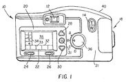
- a user interface including on screen graphics and user controls, is shown in relation to a digital electronic camera.
- the digital camera 10 is seen from a rear view, and includes an optical viewfinder 12, a zoom lens control switch 14, a handgrip area 18, and a screen operation control unit 20, all mounted on a camera housing 21.
- the screen operation control unit 20 includes a liquid crystal display (LCD) 22, first user interface controls comprising respective forward and backward image scroll buttons 24, 26 and second user interface controls comprising respective previous and next menu select buttons 28, 30, and an enter button 31.
- LCD liquid crystal display
- the forward, backward image scroll buttons 24, 26 are positioned such that the direction of user engagement is oriented parallel to a first set of graphical elements 32, which in the preferred embodiment include a strip of captured images retrieved from a list of images stored in the camera's memory.
- the previous and next menu select buttons 28, 30 are positioned such that the direction of user engagement is oriented parallel to a second set of graphical elements 34, which in the preferred embodiment is a menu bar including a number of operations or functions 1...4 that may be performed on a selected one of the images displayed in the image strip.
- the direction of user engagement of the forward, backward buttons 24, 26 and the previous, next buttons 28, 30 are oriented substantially orthogonal to each other so as to intuitively integrate user interaction with the visual presentation of the first and second sets of graphical elements 32, 34.
- Relatively lower resolution images are displayed in the frame areas of the first set of graphical elements 32, and a single relatively higher resolution image is displayed in the display area 35 that is not obscured by the graphical elements 32, 34. It is preferable to have the higher resolution image in the display area 35 to be as large as possible, and at least as large as fifty per cent of the whole area of the display 22.
- a lower resolution image corresponding to the higher resolution image is shown in a preferred position 33 in the first set of graphical elements 32.
- a known camera of the type described in Serial No. 08/928,146 further includes a dial 36 for selecting one of a plurality of operational modes, which are identified in Figure 1 as modes "A", “B", “C”, and “D". Such modes may include the functions of capturing an image, reviewing captured images, connecting to a computer, and so on.
- a color display unit is provided on the back of the camera housing, and an edit switch and a directional switch unit is provided adjacent to the display unit.
- the directional switch unit is a four directional thumbpad segmented into four different individual directional switches. The user can then manually scroll through digital film images in forward and reverse directions by utilizing the right and left directional segments of the thumbpad. In this mode, each image is shown individually as the user scrolls through the stored images.
- the edit switch is activated and a functional icon group is displayed. Then the user can utilize the up and down directional segments of the thumbpad to advance through the displayed function icons until the desired icon is highlighted.
- an electronic camera stores captured images and allows a user to relatively rapidly review any desired stored image, and to do so without repetitive actions.
- the camera displays a large image on its display device and a strip of low resolution images, including one in a preset strip position corresponding to the large image.
- the user can then navigate backwards and forward through the strip of images in the camera's storage device by pressing a forward button or a reverse button arrayed adjacent to the display device. If the user simply presses and releases the forward or reverse buttons, the low resolution images in the strip advance or reverse by one image, and the next corresponding large image is displayed.
- an electronic camera for capturing, viewing and manipulating electronic image data includes a processor for operating the camera in a plurality of modes, a display device for generating image components including one or more captured images derived from the electronic image data and a set of graphical elements, and a single controller that intuitively allows the user to cycle through the available displayed choices and options with a minimum of hassle.
- the controller includes a control element separated into four directional components arranged around a central axis and operative with the display device for navigating among the image components and a mode dial coaxial with the control element for selecting one of the modes.
- the invention provides the advantage of optimizing one-hand (e.g., right-hand) one-finger (e.g., thumb) access to each of the directional and mode controls without compromising access to any one of them. It reduces crowding, visual clutter, and perceived complexity, as well as maximizing the 'clear' area on the camera back to minimize risk of the other (e.g., left) hand interfering with a control while gripping the camera.
- This interface can be applied to both electronic cameras with an electronic display, as well as any device that can be used for image viewing and editing.
- the invention further provides the advantage of a user interface that includes a minimal set of controls which are integrated with on-back callouts and on-screen graphics in a manner as to reduce the apparent complexity and to increase the ease of using the device employing the interface.
- the interface provides strong spatial cues that line up the on-screen graphics with the user controls. This association of graphics and callouts with user controls provides an intuitive method of interacting with an image viewing and editing device.
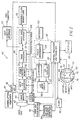
- a digital camera 40 includes a zoom lens section 42 for directing image light toward an image sensor 44, a processing section 46, and a removable output memory 48, such as a flash memory card.
- the image sensor 44 is typically a color sensor, and includes a color filter array, such as the well-known Bayer pattern (see U.S. Patent No. 3,971,065).
- the processing section 46 includes an analog signal processing and A/D converter 50, a DRAM buffer memory 52, an image processing section 54 (which may be a programmable DSP capable processor, such as a Hitachi SH-DSP processor), and an output interface 56 to the removable memory 48.
- the camera includes a host computer interface 57 for directly connecting the camera 40 to a host computer, for example, to download images.
- the DRAM buffer memory 52 has sufficient memory space for at least one full resolution image captured by the image sensor 44.
- the camera 40 also includes a zooming optical viewfinder 58, an image liquid crystal display (LCD) 60, a control section 62 including a control processor and timing generator 64, a flash unit 66, a status LCD 68, and a user interface comprising a group of user controls including a combination control 70.
- LCD liquid crystal display
- the control processor and timing generator 64 operates the camera in a variety of modes, e.g., to capture images, to review captured images, to connect to an external computer, and so on, and provides a set of graphical elements for the user interface (e.g., the elements 32 and 34 described in connection with Figure 1), which may change depending on the mode selected.
- the combination control 70 includes a disk-shaped select button 78 surrounded by a mode dial 72, which further includes a knob 74 and a pointer 76.
- a mode dial 72 which further includes a knob 74 and a pointer 76.
- the mode dial 72 comprises an outer ring surrounding the inner select button 78, which includes markers 80 for selection of four separate directions. As shown in cross section in Figure 4, the mode dial 72 is captured between a rear cover 82 of the camera and a socket 84 such that switch contacts 86 engage a switching pattern (not shown) on a printed circuit board (PCB) 88 in order to enable a selected mode.
- the select button 78 is mounted atop a multi-function tactile switch 90 so as to be tilted in different directions and provide a different output signal to the PCB 88 for each direction of movement.
- a ready light 92 that is connected to the control processor and timing generator 64.
- a set of autofocus and autoexposure detectors 94 provide data to the control processor and timing generator 64 for driving zoom and focus motors 96 connected to the zoom lens 42, and for initiatng an exposure by enabling clock drivers 98 in order to activate the image sensor 44.
- the control section 62 further includes a power management controller 100, which is connected to the control processor and timing generator 64 for conserving power demands by the various components of the camera 40. Power supplied by batteries 102 is applied on demand to the clock drivers 98, the processing section 46, and the image LCD 60. More specifically, a capture power enable line 104 supplies power to the clock drivers 98 and the analog signal processing and A/D converter 50 and a separate process power enable line 106 supplies power to the DRAM buffer memory 52, the image processing section 54, and the memory card interface 56.
- the power management controller 100 also enables LCD drivers 108 to input data from the DRAM buffer memory 52 to the image LCD 60, and further enables an LCD backlight 110 to provide a variable amount of backlight to the image on the image LCD 60.
- the image LCD 60 is a color LCD for displaying color images.
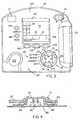
- Figure 3 shows a view of a back surface 40' of the digital camera 40 showing the combination four way directional and mode control interface according to the invection (features common to Figures 1, 2 and 3 retain the same reference characters).
- the back of the camera 40 includes a right-hand grip 120 and a left thumbgrip 122.
- the combination control 70 is positioned relative to the right-hand grip 120 so as to optimize right-hand thumb access to the mode dial 72 and to the select button 78.
- the combination control 70 is also positioned in a rightward location to maximize a clear area 124 on the camera back 40 to minimize the risk of the left hand interfering with one of the controls while gripping the camera 40.
- the mode dial 72 constitutes an outer ring mounted on the circumferential exterior of the combination control 70.
- This outer ring may be plastic or metal with, e.g., a bright, metallic finish.
- the ring may be narrow or wide, but would preferably feature two protrusions: the knob 74 to serve as a 'lever' to facilitate turning the mode dial, particularly by use of the right thumb; and the pointer 76 to indicate the mode selection from a group of mode callouts 126.
- the mode callouts 126 would preferably be printed on the camera back 40', and possibly color-coded as well.
- the select button 78 includes four raised actuation points: left/right actuation points 128/130 and up/down actuation points 132/134.
- actuation points 128/130 and 132/134 are used to navigate among the image components displayed on the display 60, that is, among the captured images or the graphical elements.
- the button area may be plastic (hard) or elastomeric (soft) material.
- the actuation points 128/130 and 132/134 would be biased toward the outer perimeter of the circular inner area to ensure adequate tactile separation between contact points.
- Color and finish of the select button(s) 78 might be anything desirable, but would be designed so as not to supersede the visual dominance of the mode dial.
- the camera back 40' also includes a display button 136, which is pressed in order to turn on the display 60, and a menu button 138, which is pressed to cycle among various menus for a given mode selected by the mode dial 72.
- Three soft keys 140, 142 and 144 are provided on the camera back 40', and access changeable functions dependent upon the menu selection. Text describing the functions is written in a bar 146 along the bottom of the display 60. For instance, Figure 3 shows the left key 140 active as a delete function in the info mode (i.e., all keys are not used in each menu selection).
- the left/right actuation points 128/130 are positioned such that the direction of user engagement is oriented parallel to the first set of graphical elements 32, which may include a strip of captured images retrieved from a list of images stored in the camera's memory.
- the up/down actuation points 132/134 are positioned such that the direction of user engagement is oriented parallel to the second set of graphical elements 34, which may be a menu bar including a number of operations or functions 1...4 that may be performed on a selected one of the images displayed in the image strip.
- the direction of user engagement of the left/right actuation points 128/130 and the up/down actuation points 132/134 are oriented substantially orthogonal to each other so as to intuitively integrate user interaction with the visual presentation of the first and second sets of graphical elements 32, 34.
- Relatively lower resolution images are displayed in the flame areas of the first set of graphical elements 32, and a single relatively higher resolution image is displayed in the display area 35 that is not obscured by the graphical elements 32, 34.
- a lower resolution image corresponding to the higher resolution image is shown in a preferred position 33 in the first set of graphical elements 22.
- a camera wherein the directional components are user engageable buttons arranged in a circular pattern around the central axis; a camera wherein the directional components are elements of a tactile switch that is covered with a button that can be tilted in different directions to engage the separate components; a camera wherein the set of graphical elements vary depending on the selected mode; a camera wherein the first user control comprises two directional controls that are oriented parallel to the first set of graphical elements for initiating one or more operations represented by the first set of graphical elements; a camera wherein the second user control comprises two directional controls that are oriented parallel to the second set of graphical elements for initiating one or more operations represented by the second set of graphical elements; a camera wherein the directional controls are user engageable buttons arranged in a circular pattern around the central axis; a camera wherein the directional controls are elements of a tactile switch that is covered with a button that can be tilted in different directions to engage the separate controls; a camera wherein the first set of
Abstract
Description
- Reference is made to commonly assigned copending applications Serial No. 08/769,573 , entitled "Electronic Camera with Image Review" and filed December 19, 1996 in the names of Michael E. Miller and Richard E. Lourette; and Serial No. 08/928,146, entitled "User Interface for Electronic Image Viewing Apparatus" and filed September 12, 1997 in the names of Michael E. Miller, Richard W. Lourette, Peter C. Fellegara, Carolyn A. Bussi, Michael J. Telek, Matthew E. Hunter, and Duncan R. Kerr; and Serial Number 08/803,338, entitled "Electronic Camera with Internal Fixed Album Memory" and filed February 20, 1997 in the names of Richard W. Lourette, Peter Fellegara, Michael E. Miller, and Linda M. Antos, each of which are assigned to the assignee of this application.
- The invention relates generally to the field of electronic photography, and in particular to a user interface for an electronic camera that is connectable to a computer and capable of image viewing and editing.
- When designing an electronic camera, the human interface with the camera must support the operational functions of the camera, as well as the selection and viewing of captured images. As used herein, the human (or user) interface refers to the totality of the human interaction with the system, and the means for enabling such interaction, e.g., including the information presented by the system to the user, and by the user to the system, as well as the devices that enable such presentations. The system must also provide the ability to select among operational functions, as well as apply actions against these images, such as magnifying the images, deleting the images, or sharing the images via a display device. Such a system will often employ a very small display and limited area for user controls; therefore, it is important for the user interface to have as few buttons and switches as possible, to present images that are visible on the small display, and to encourage interaction that is as intuitive as possible so as to tie usage of the buttons and switches on the camera to the graphics on the display.
- In copending Serial No. 08/928,146, a user interface, including on screen graphics and user controls, is shown in relation to a digital electronic camera. Referring to Figure 1, the
digital camera 10 is seen from a rear view, and includes anoptical viewfinder 12, a zoomlens control switch 14, ahandgrip area 18, and a screenoperation control unit 20, all mounted on acamera housing 21. More specifically, the screenoperation control unit 20 includes a liquid crystal display (LCD) 22, first user interface controls comprising respective forward and backwardimage scroll buttons buttons enter button 31. - The forward, backward
image scroll buttons graphical elements 32, which in the preferred embodiment include a strip of captured images retrieved from a list of images stored in the camera's memory. The previous and next menu selectbuttons graphical elements 34, which in the preferred embodiment is a menu bar including a number of operations or functions 1...4 that may be performed on a selected one of the images displayed in the image strip. Consequently, the direction of user engagement of the forward, backwardbuttons next buttons graphical elements graphical elements 32, and a single relatively higher resolution image is displayed in thedisplay area 35 that is not obscured by thegraphical elements display area 35 to be as large as possible, and at least as large as fifty per cent of the whole area of thedisplay 22. Furthermore, a lower resolution image corresponding to the higher resolution image is shown in apreferred position 33 in the first set ofgraphical elements 32. A known camera of the type described in Serial No. 08/928,146 further includes adial 36 for selecting one of a plurality of operational modes, which are identified in Figure 1 as modes "A", "B", "C", and "D". Such modes may include the functions of capturing an image, reviewing captured images, connecting to a computer, and so on. - In copending Serial Number 08/803,338, a color display unit is provided on the back of the camera housing, and an edit switch and a directional switch unit is provided adjacent to the display unit. The directional switch unit is a four directional thumbpad segmented into four different individual directional switches. The user can then manually scroll through digital film images in forward and reverse directions by utilizing the right and left directional segments of the thumbpad. In this mode, each image is shown individually as the user scrolls through the stored images. In a separate edit level, the edit switch is activated and a functional icon group is displayed. Then the user can utilize the up and down directional segments of the thumbpad to advance through the displayed function icons until the desired icon is highlighted.
- In copending Serial Number 08/769,575, an electronic camera stores captured images and allows a user to relatively rapidly review any desired stored image, and to do so without repetitive actions. The camera displays a large image on its display device and a strip of low resolution images, including one in a preset strip position corresponding to the large image. The user can then navigate backwards and forward through the strip of images in the camera's storage device by pressing a forward button or a reverse button arrayed adjacent to the display device. If the user simply presses and releases the forward or reverse buttons, the low resolution images in the strip advance or reverse by one image, and the next corresponding large image is displayed.
- None of the foregoing systems integrate mode selection, such as capture, connect (to a host computer), and review (of captured images), with directional navigation, such as up/down and left/right, into a single control presentation that intuitively allows the user to cycle through the available choices and options with a minimum of hassle.
- The present invention is directed to overcoming one or more of the problems set forth above. Briefly summarized, according to one aspect of the present invention, an electronic camera for capturing, viewing and manipulating electronic image data includes a processor for operating the camera in a plurality of modes, a display device for generating image components including one or more captured images derived from the electronic image data and a set of graphical elements, and a single controller that intuitively allows the user to cycle through the available displayed choices and options with a minimum of hassle. The controller includes a control element separated into four directional components arranged around a central axis and operative with the display device for navigating among the image components and a mode dial coaxial with the control element for selecting one of the modes.
- Despite the simplicity of the interface, the invention provides the advantage of optimizing one-hand (e.g., right-hand) one-finger (e.g., thumb) access to each of the directional and mode controls without compromising access to any one of them. It reduces crowding, visual clutter, and perceived complexity, as well as maximizing the 'clear' area on the camera back to minimize risk of the other (e.g., left) hand interfering with a control while gripping the camera. This interface can be applied to both electronic cameras with an electronic display, as well as any device that can be used for image viewing and editing.
- The invention further provides the advantage of a user interface that includes a minimal set of controls which are integrated with on-back callouts and on-screen graphics in a manner as to reduce the apparent complexity and to increase the ease of using the device employing the interface. The interface provides strong spatial cues that line up the on-screen graphics with the user controls. This association of graphics and callouts with user controls provides an intuitive method of interacting with an image viewing and editing device.
- These and other aspects, objects, features and advantages of the present invention will be more clearly understood and appreciated from a review of the following detailed description of the preferred embodiments and appended claims, and by reference to the accompanying drawings.
-
- FIG. 1 is a view of a back of an electronic camera employing a user interface according to the prior art.
- FIG. 2 is a block diagram of a digital camera including a combination four-way directional and mode control according to the invention.
- FIG. 3 is a view of an electronic camera using the four-way control shown in FIG. 2 according to the invention.
- FIG. 4 is a cross section of the combination four-way directional and mode control as shown in FIGS. 2 and 3.
-
- Because digital cameras employing electronic sensors, as well as electronic processing and storage, are well known, the present description will be directed in particular to elements forming part of, or cooperating more directly with, apparatus in accordance with the present invention. Elements not specifically shown or described herein may be selected from those known in the art. Certain aspects of the embodiments to be described may be provided in software. Given the system as described in the following materials, all such software implementation needed to practice the invention is conventional and within the ordinary skill in such arts.
- Referring now to Figure 2, a
digital camera 40 includes azoom lens section 42 for directing image light toward animage sensor 44, aprocessing section 46, and aremovable output memory 48, such as a flash memory card. Theimage sensor 44 is typically a color sensor, and includes a color filter array, such as the well-known Bayer pattern (see U.S. Patent No. 3,971,065). Theprocessing section 46 includes an analog signal processing and A/D converter 50, aDRAM buffer memory 52, an image processing section 54 (which may be a programmable DSP capable processor, such as a Hitachi SH-DSP processor), and anoutput interface 56 to theremovable memory 48. In addition, the camera includes ahost computer interface 57 for directly connecting thecamera 40 to a host computer, for example, to download images. - The
DRAM buffer memory 52 has sufficient memory space for at least one full resolution image captured by theimage sensor 44. Thecamera 40 also includes a zoomingoptical viewfinder 58, an image liquid crystal display (LCD) 60, acontrol section 62 including a control processor andtiming generator 64, aflash unit 66, astatus LCD 68, and a user interface comprising a group of user controls including acombination control 70. The control processor andtiming generator 64, either by itself or in combination with theprocessing section 46, operates the camera in a variety of modes, e.g., to capture images, to review captured images, to connect to an external computer, and so on, and provides a set of graphical elements for the user interface (e.g., theelements - In the preferred embodiment, the
combination control 70 includes a disk-shapedselect button 78 surrounded by amode dial 72, which further includes aknob 74 and apointer 76. One of the aforementioned modes, including "capture", "review" (of captured images), "connect" (to a host computer), is selected by positioning thepointer 76 opposite the selected mode. Themode dial 72 comprises an outer ring surrounding the innerselect button 78, which includesmarkers 80 for selection of four separate directions. As shown in cross section in Figure 4, themode dial 72 is captured between arear cover 82 of the camera and asocket 84 such thatswitch contacts 86 engage a switching pattern (not shown) on a printed circuit board (PCB) 88 in order to enable a selected mode. Theselect button 78 is mounted atop a multi-functiontactile switch 90 so as to be tilted in different directions and provide a different output signal to thePCB 88 for each direction of movement. - Nearby, or within, the optical viewfinder is a
ready light 92 that is connected to the control processor andtiming generator 64. A set of autofocus andautoexposure detectors 94 provide data to the control processor andtiming generator 64 for driving zoom and focusmotors 96 connected to thezoom lens 42, and for initiatng an exposure by enabling clock drivers 98 in order to activate theimage sensor 44. - The
control section 62 further includes apower management controller 100, which is connected to the control processor andtiming generator 64 for conserving power demands by the various components of thecamera 40. Power supplied bybatteries 102 is applied on demand to the clock drivers 98, theprocessing section 46, and theimage LCD 60. More specifically, a capture power enable line 104 supplies power to the clock drivers 98 and the analog signal processing and A/D converter 50 and a separate process power enableline 106 supplies power to theDRAM buffer memory 52, theimage processing section 54, and thememory card interface 56. Thepower management controller 100 also enablesLCD drivers 108 to input data from theDRAM buffer memory 52 to theimage LCD 60, and further enables anLCD backlight 110 to provide a variable amount of backlight to the image on theimage LCD 60. In the preferred embodiment, theimage LCD 60 is a color LCD for displaying color images. - Figure 3 shows a view of a back surface 40' of the
digital camera 40 showing the combination four way directional and mode control interface according to the invection (features common to Figures 1, 2 and 3 retain the same reference characters). The back of thecamera 40 includes a right-hand grip 120 and aleft thumbgrip 122. Thecombination control 70 is positioned relative to the right-hand grip 120 so as to optimize right-hand thumb access to themode dial 72 and to theselect button 78. Thecombination control 70 is also positioned in a rightward location to maximize aclear area 124 on the camera back 40 to minimize the risk of the left hand interfering with one of the controls while gripping thecamera 40. - The
mode dial 72 constitutes an outer ring mounted on the circumferential exterior of thecombination control 70. This outer ring may be plastic or metal with, e.g., a bright, metallic finish. The ring may be narrow or wide, but would preferably feature two protrusions: theknob 74 to serve as a 'lever' to facilitate turning the mode dial, particularly by use of the right thumb; and thepointer 76 to indicate the mode selection from a group ofmode callouts 126. Themode callouts 126 would preferably be printed on the camera back 40', and possibly color-coded as well. Theselect button 78 includes four raised actuation points: left/right actuation points 128/130 and up/down actuation points 132/134. These points may be formed on a single select button, such as shown in Figure 4, or may constitute separate button segments; in either case, the actuation points 128/130 and 132/134 are used to navigate among the image components displayed on thedisplay 60, that is, among the captured images or the graphical elements. The button area may be plastic (hard) or elastomeric (soft) material. The actuation points 128/130 and 132/134 would be biased toward the outer perimeter of the circular inner area to ensure adequate tactile separation between contact points. Color and finish of the select button(s) 78 might be anything desirable, but would be designed so as not to supersede the visual dominance of the mode dial. - The camera back 40' also includes a
display button 136, which is pressed in order to turn on thedisplay 60, and amenu button 138, which is pressed to cycle among various menus for a given mode selected by themode dial 72. Threesoft keys bar 146 along the bottom of thedisplay 60. For instance, Figure 3 shows theleft key 140 active as a delete function in the info mode (i.e., all keys are not used in each menu selection). - The left/right actuation points 128/130 are positioned such that the direction of user engagement is oriented parallel to the first set of
graphical elements 32, which may include a strip of captured images retrieved from a list of images stored in the camera's memory. The up/down actuation points 132/134 are positioned such that the direction of user engagement is oriented parallel to the second set ofgraphical elements 34, which may be a menu bar including a number of operations or functions 1...4 that may be performed on a selected one of the images displayed in the image strip. Consequently, the direction of user engagement of the left/right actuation points 128/130 and the up/down actuation points 132/134 are oriented substantially orthogonal to each other so as to intuitively integrate user interaction with the visual presentation of the first and second sets ofgraphical elements graphical elements 32, and a single relatively higher resolution image is displayed in thedisplay area 35 that is not obscured by thegraphical elements preferred position 33 in the first set ofgraphical elements 22. - Other aspects of the invention include: a camera wherein the directional components are user engageable buttons arranged in a circular pattern around the central axis; a camera wherein the directional components are elements of a tactile switch that is covered with a button that can be tilted in different directions to engage the separate components; a camera wherein the set of graphical elements vary depending on the selected mode; a camera wherein the first user control comprises two directional controls that are oriented parallel to the first set of graphical elements for initiating one or more operations represented by the first set of graphical elements; a camera wherein the second user control comprises two directional controls that are oriented parallel to the second set of graphical elements for initiating one or more operations represented by the second set of graphical elements; a camera wherein the directional controls are user engageable buttons arranged in a circular pattern around the central axis; a camera wherein the directional controls are elements of a tactile switch that is covered with a button that can be tilted in different directions to engage the separate controls; a camera wherein the first set of graphical elements includes a plurality of pictorial elements presented in the form of a filmstrip; an apparatus wherein said display device generates a larger rendition of an image and the pictorial elements included in the first set of graphical elements provide a plurality of smaller images in the form of a filmstrip including one smaller image that corresponds to the larger image; an apparatus wherein the second set of graphical elements is a plurality of operations presented in the form of a menu bar.
- The invention has been described with reference to a preferred embodiment. However, it will be appreciated that variations and modifications can be effected by a person of ordinary skill in the art without departing from the scope of the invention.
-
- 10
- camera
- 12
- optical viewfinder
- 14
- zoom lens control switch
- 18
- handgrip area
- 20
- screen operation control unit
- 21
- camera housing
- 22
- LCD
- 24
- forward image scroll button
- 26
- backward image scroll button
- 28
- up menu select button
- 30
- down menu select button
- 31
- enter button
- 32
- first set of graphical elements
- 33
- preferred position
- 34
- second set of graphical elements
- 35
- display area
- 36
- dial
- 40
- digital camera
- 42
- zoom lens section
- 44
- image sensor
- 46
- processing section
- 48
- removable output memory
- 50
- analog signal processor and A/D converter
- 52
- DRAM buffer memory
- 54
- image processing section
- 56
- card interface
- 57
- host computer interface
- 58
- zooming optical viewfinder
- 60
- image LCD
- 62
- control section
- 64
- control processor and timing generator
- 66
- flash unit
- 68
- status LCD
- 70
- combination control
- 72
- mode dial
- 74
- knob
- 76
- pointer
- 78
- select button
- 80
- markers
- 82
- rear cover
- 84
- socket
- 86
- switch contacts
- 88
- printed circuit board
- 90
- multi-function tactile switch
- 92
- ready light
- 94
- autofocus and autoexposure detectors
- 96
- zoom and focus motors
- 98
- clock drivers
- 100
- power management controller
- 102
- batteries
- 104
- capture power enable line
- 106
- process power enable line
- 108
- LCD drivers
- 110
- LCD backlight
- 120
- right-hand grip
- 122
- left-thumb grip
- 124
- clear area
- 126
- mode callouts
- 128
- left actuation point
- 130
- right actuation point
- 132
- up actuation point
- 134
- down actuation point
- 136
- display button
- 138
- menu button
- 140
- soft key
- 142
- soft key
- 144
- soft key
- 146
- bar
Claims (10)
- An electronic camera for capturing, viewing and manipulating electronic image data, said apparatus comprising:a processor for operating the camera in a plurality of modes;a display device for generating image components including one or more captured images derived from the electronic image data and a set of graphical elements;a control element separated into four directional components arranged around a central axis and operative with the display device for navigating among the image components; anda mode dial coaxial with the control element for selecting one of the modes.
- A camera as claimed in claim 1 wherein the control element is an inner disk including the four directional components and the mode dial is an outer ring positioned around the inner disk.
- A camera as claimed in claim 1 wherein the directional components include up/down controls for navigating up/down among the image components and left/right controls for navigating left/right among the image components.
- A camera as claimed in claim 1 wherein the camera includes a housing having a handgrip and the control element and the mode dial are positioned on the housing so that they are accessible to a thumb when the handgrip is grasped.
- A camera as claimed in claim 4 wherein the mode dial includes a knob that is accessible to the thumb.
- A camera as claimed in claim 1 wherein the processor is operable in a capture mode, and the mode dial allows selection of a capture mode.
- A camera as claimed in claim 1 wherein the camera is connectible to a host computer, the processor is further operable in a mode connecting the camera to the host computer, and the mode dial allows selection of a connect mode that connects the camera to the host computer.
- A camera as claimed in claim 1 wherein the processor is further operable in a review mode for reviewing captured images, and the mode dial allows selection of a review mode for reviewing captured images.
- An electronic camera for capturing, viewing and manipulating electronic image data corresponding to one or more images, said apparatus comprising:a processor for operating the camera in a plurality of operational modes;a display device for generating a displayed image from the electronic image data, and for further displaying first and second sets of graphical elements, said first set oriented in a direction substantially orthogonal to the second set of graphical elements;a circular control element arranged around a central axis, said control element including a first user control in which the direction of user engagement is oriented parallel to the first set of graphical elements for initiating one or more operations represented by the first set of graphical elements; and a second user control in which the direction of user engagement is oriented parallel to the second set of graphical elements for initiating one or more operations represented by the second set of graphical elements, wherein the directions of user engagement for the first and second user controls are oriented substantially orthogonal to each other so as to intuitively integrate user interaction with the visual presentation of the first and second sets of graphical elements; anda mode dial coaxial with the control element for selecting one of the modes.
- A graphical user interface operable with an image capture device for selecting and viewing electronic image data corresponding to one or more images, and for controlling the presentation and editing of the images, said interface comprising:a display device for generating at least one displayed image from the electronic image data, said display device usable with the capture device in a plurality of operational modes, including a capture mode, a review mode, and a mode for connecting to an external computer;means for producing on the display device first and second sets of graphical elements arranged orthogonal to each other, said first set including pictorial elements representing low resolution versions of a plurality of electronic images including the displayed image and said second set including graphical symbols identifying a plurality of operations that can be carried out on the displayed image;a first set of two directional controls that are arranged on a first axis parallel to the first set of graphical elements in order to scroll through the low resolution versions of the electronic images;a second set of two directional controls that are arranged on a second axis parallel to the second set of graphical elements in order to select an operation;a user input element grouping the first and second set of directional controls together relative to a single central axis, so as to provide actuable sections arranged around the central axis in a circle, thereby intuitively integrating user interaction with the visual presentation of the first and second sets of graphical elements; anda mode dial coaxial with the user input element for selecting one of the operational modes.
Applications Claiming Priority (2)
| Application Number | Priority Date | Filing Date | Title |
|---|---|---|---|
| US48416 | 1998-03-26 | ||
| US09/048,416 US6519003B1 (en) | 1998-03-26 | 1998-03-26 | Camera with combination four-way directional and mode control interface |
Publications (2)
| Publication Number | Publication Date |
|---|---|
| EP0946045A2 true EP0946045A2 (en) | 1999-09-29 |
| EP0946045A3 EP0946045A3 (en) | 2001-01-24 |
Family
ID=21954453
Family Applications (1)
| Application Number | Title | Priority Date | Filing Date |
|---|---|---|---|
| EP99200766A Withdrawn EP0946045A3 (en) | 1998-03-26 | 1999-03-15 | Camera with combination four-way directional and mode control interface |
Country Status (3)
| Country | Link |
|---|---|
| US (1) | US6519003B1 (en) |
| EP (1) | EP0946045A3 (en) |
| JP (1) | JP2000066281A (en) |
Cited By (6)
| Publication number | Priority date | Publication date | Assignee | Title |
|---|---|---|---|---|
| US6636264B1 (en) * | 1998-05-20 | 2003-10-21 | Fuji Photo Film Co., Ltd. | Portable electronic apparatus |
| US6683644B1 (en) * | 1998-05-20 | 2004-01-27 | Fuji Photo Film Co., Ltd. | Portable electronic apparatus with flat display |
| US6683653B1 (en) * | 1998-02-02 | 2004-01-27 | Fuji Photo Film Co., Ltd. | Electronic camera and dial control device of electronic equipment |
| GB2397206A (en) * | 2002-11-21 | 2004-07-14 | Hewlett Packard Development Co | Heuristically determined menu arrangement |
| EP1575257A1 (en) * | 2004-03-10 | 2005-09-14 | Samsung Electronics Co., Ltd. | A selection switch and display |
| US7209174B2 (en) | 2002-02-27 | 2007-04-24 | Hewlett-Packard Development Company, L.P. | Movable status display within a camera-back display of an image capturing device |
Families Citing this family (40)
| Publication number | Priority date | Publication date | Assignee | Title |
|---|---|---|---|---|
| JP3761999B2 (en) * | 1996-11-20 | 2006-03-29 | キヤノン株式会社 | Information input device for optical equipment |
| US20020067426A1 (en) * | 1997-04-10 | 2002-06-06 | Hideki Nagata | Electronic camera having a phoelectric sensor device |
| US7602424B2 (en) * | 1998-07-23 | 2009-10-13 | Scenera Technologies, Llc | Method and apparatus for automatically categorizing images in a digital camera |
| JP2000050141A (en) * | 1998-07-30 | 2000-02-18 | Minolta Co Ltd | Digital camera |
| JP4186293B2 (en) * | 1999-02-10 | 2008-11-26 | 株式会社ニコン | Electronic camera |
| US6952229B1 (en) | 1999-04-13 | 2005-10-04 | Seiko Epson Corporation | Digital camera having input devices and a display capable of displaying a plurality of set information items |
| JP4456206B2 (en) * | 1999-05-25 | 2010-04-28 | 富士フイルム株式会社 | Digital camera and image display method |
| GB9920327D0 (en) * | 1999-08-28 | 1999-11-03 | Koninkl Philips Electronics Nv | Menu display for a graphical user interface |
| JP2001075712A (en) * | 1999-08-31 | 2001-03-23 | Sony Corp | Information processor, its method and program storage medium |
| JP4101421B2 (en) * | 1999-12-27 | 2008-06-18 | 富士フイルム株式会社 | INPUT UNIT, INFORMATION RECORDING DEVICE USING INPUT UNIT, AND DIGITAL CAMERA |
| US7319490B2 (en) * | 2000-01-21 | 2008-01-15 | Fujifilm Corporation | Input switch with display and image capturing apparatus using the same |
| US6710805B1 (en) * | 2000-01-26 | 2004-03-23 | Hewlett-Packard Development Company, L.P. | Simplified user interface for digital camera |
| DE10113084A1 (en) * | 2001-03-17 | 2002-09-19 | Leica Microsystems | Autofocus microscope system |
| US20020146250A1 (en) * | 2001-03-21 | 2002-10-10 | Stockton Kenneth R. | Information switch and method for a digital camera |
| US7079110B2 (en) * | 2001-04-30 | 2006-07-18 | Microsoft Corporation | Input device including a wheel assembly for scrolling an image in multiple directions |
| US20030035052A1 (en) * | 2001-08-20 | 2003-02-20 | Baron John M. | User selection device for camera navigation |
| JP4518716B2 (en) * | 2001-09-25 | 2010-08-04 | 三洋電機株式会社 | Digital camera |
| US6987505B1 (en) * | 2002-06-03 | 2006-01-17 | Microsoft Corporation | Modular scroll wheel with integral detent-engaging spring tab |
| US7042441B2 (en) * | 2002-06-28 | 2006-05-09 | Microsoft Corporation | Input device including a scroll wheel assembly for manipulating an image in multiple directions |
| US7075516B2 (en) | 2003-03-07 | 2006-07-11 | Microsoft Corporation | Scroll wheel assembly for scrolling an image in multiple directions |
| JP3700031B2 (en) * | 2003-03-10 | 2005-09-28 | コニカミノルタフォトイメージング株式会社 | Digital camera |
| JP2004294685A (en) * | 2003-03-26 | 2004-10-21 | Canon Inc | Television lens |
| KR20050075895A (en) * | 2004-01-16 | 2005-07-25 | 삼성전자주식회사 | Digital camcorder |
| KR20050112567A (en) * | 2004-05-27 | 2005-12-01 | 삼성테크윈 주식회사 | Method of controlling digital photographing apparatus for convenient replay |
| US7443382B2 (en) * | 2004-08-27 | 2008-10-28 | Microsoft Corporation | Scroll wheel carriage |
| JP2006221036A (en) * | 2005-02-14 | 2006-08-24 | Fuji Photo Film Co Ltd | Camera |
| JP4727285B2 (en) * | 2005-04-22 | 2011-07-20 | 三星電子株式会社 | Digital camera |
| KR101176943B1 (en) * | 2006-05-09 | 2012-08-30 | 삼성전자주식회사 | A function key assembly for fortable device |
| US8359248B2 (en) * | 2006-08-24 | 2013-01-22 | Blue Pillar, Inc. | Systems, methods, and devices for managing emergency power supply systems |
| US7548826B2 (en) * | 2006-08-24 | 2009-06-16 | Blue Pillar, Inc. | Power monitoring and testing |
| JP5075436B2 (en) * | 2007-03-14 | 2012-11-21 | 株式会社三共 | Game machine |
| USD609714S1 (en) | 2007-03-22 | 2010-02-09 | Fujifilm Corporation | Electronic camera |
| US20090081973A1 (en) * | 2007-09-26 | 2009-03-26 | Analog Devices, Inc. | Multi-slot power control for wireless transmission |
| US8189101B2 (en) * | 2007-10-26 | 2012-05-29 | Cisco Technology, Inc. | Data connector for an electronics device |
| USD751091S1 (en) | 2008-10-29 | 2016-03-08 | Fujifilm Corporation | Display screen for electronic camera with computer generated icon |
| USD803854S1 (en) * | 2009-04-29 | 2017-11-28 | Fujifilm Corporation | Combined electronic camera display screen with icon and electronic camera |
| US8863042B2 (en) * | 2012-01-24 | 2014-10-14 | Charles J. Kulas | Handheld device with touch controls that reconfigure in response to the way a user operates the device |
| EP2819393A1 (en) * | 2012-02-24 | 2014-12-31 | Sony Corporation | Parameter adjusting device, parameter adjusting method and storage medium |
| USD731543S1 (en) * | 2012-07-03 | 2015-06-09 | Fujifilm Corporation | Digital camera display screen with graphical user interface |
| JP6464626B2 (en) * | 2013-09-27 | 2019-02-06 | リコーイメージング株式会社 | Operation key |
Citations (4)
| Publication number | Priority date | Publication date | Assignee | Title |
|---|---|---|---|---|
| US5223888A (en) * | 1990-02-05 | 1993-06-29 | Canon Kabushiki Kaisha | Camera |
| JPH09189933A (en) * | 1996-01-09 | 1997-07-22 | Canon Inc | Remote control device for camera and camera system using the same |
| WO1998012868A1 (en) * | 1996-09-19 | 1998-03-26 | Flashpoint Technology, Inc. | A method and system for displaying images in the interface of a digital camera |
| JPH10161222A (en) * | 1996-12-05 | 1998-06-19 | Nikon Corp | Operating member and display device for camera |
Family Cites Families (7)
| Publication number | Priority date | Publication date | Assignee | Title |
|---|---|---|---|---|
| JPH0427280A (en) * | 1990-05-22 | 1992-01-30 | Canon Inc | Camera integrated video recorder device |
| US5747654A (en) | 1993-06-14 | 1998-05-05 | The United States Of America As Represented By The Department Of Health And Human Services | Recombinant disulfide-stabilized polypeptide fragments having binding specificity |
| US5430511A (en) | 1993-12-21 | 1995-07-04 | Sensormatic Electronics Corporation | Controller for a surveillance assembly |
| JP3562055B2 (en) | 1994-09-07 | 2004-09-08 | 株式会社ニコン | Camera setting display device |
| US5815201A (en) * | 1995-02-21 | 1998-09-29 | Ricoh Company, Ltd. | Method and system for reading and assembling audio and image information for transfer out of a digital camera |
| US5978016A (en) | 1997-02-20 | 1999-11-02 | Eastman Kodak Company | Electronic camera with internal fixed album memory |
| US6310703B1 (en) | 1998-08-28 | 2001-10-30 | Jds Uniphase Corporation | Method and apparatus for optical performance monitoring in wavelength division multiplexed fiber optical systems |
-
1998
- 1998-03-26 US US09/048,416 patent/US6519003B1/en not_active Expired - Lifetime
-
1999
- 1999-03-15 EP EP99200766A patent/EP0946045A3/en not_active Withdrawn
- 1999-03-17 JP JP11071771A patent/JP2000066281A/en active Pending
Patent Citations (4)
| Publication number | Priority date | Publication date | Assignee | Title |
|---|---|---|---|---|
| US5223888A (en) * | 1990-02-05 | 1993-06-29 | Canon Kabushiki Kaisha | Camera |
| JPH09189933A (en) * | 1996-01-09 | 1997-07-22 | Canon Inc | Remote control device for camera and camera system using the same |
| WO1998012868A1 (en) * | 1996-09-19 | 1998-03-26 | Flashpoint Technology, Inc. | A method and system for displaying images in the interface of a digital camera |
| JPH10161222A (en) * | 1996-12-05 | 1998-06-19 | Nikon Corp | Operating member and display device for camera |
Non-Patent Citations (2)
| Title |
|---|
| PATENT ABSTRACTS OF JAPAN vol. 1997, no. 11, 28 November 1997 (1997-11-28) & JP 09 189933 A (CANON INC), 22 July 1997 (1997-07-22) * |
| PATENT ABSTRACTS OF JAPAN vol. 1998, no. 11, 30 September 1998 (1998-09-30) & JP 10 161222 A (NIKON CORP), 19 June 1998 (1998-06-19) * |
Cited By (7)
| Publication number | Priority date | Publication date | Assignee | Title |
|---|---|---|---|---|
| US6683653B1 (en) * | 1998-02-02 | 2004-01-27 | Fuji Photo Film Co., Ltd. | Electronic camera and dial control device of electronic equipment |
| US6636264B1 (en) * | 1998-05-20 | 2003-10-21 | Fuji Photo Film Co., Ltd. | Portable electronic apparatus |
| US6683644B1 (en) * | 1998-05-20 | 2004-01-27 | Fuji Photo Film Co., Ltd. | Portable electronic apparatus with flat display |
| US7209174B2 (en) | 2002-02-27 | 2007-04-24 | Hewlett-Packard Development Company, L.P. | Movable status display within a camera-back display of an image capturing device |
| GB2397206A (en) * | 2002-11-21 | 2004-07-14 | Hewlett Packard Development Co | Heuristically determined menu arrangement |
| EP1575257A1 (en) * | 2004-03-10 | 2005-09-14 | Samsung Electronics Co., Ltd. | A selection switch and display |
| CN100417194C (en) * | 2004-03-10 | 2008-09-03 | 三星电子株式会社 | Mode selection switch of photographing device |
Also Published As
| Publication number | Publication date |
|---|---|
| EP0946045A3 (en) | 2001-01-24 |
| US6519003B1 (en) | 2003-02-11 |
| JP2000066281A (en) | 2000-03-03 |
Similar Documents
| Publication | Publication Date | Title |
|---|---|---|
| US6519003B1 (en) | Camera with combination four-way directional and mode control interface | |
| US6310648B1 (en) | User interface for electronic image viewing apparatus | |
| US6122003A (en) | Method and apparatus for changing operating modes of an image capture device | |
| US7106375B2 (en) | Mutual display support for a digital information/imaging system | |
| US7827508B2 (en) | Hotkey function in digital camera user interface | |
| EP0981898B1 (en) | A digital camera with multiple operating modes | |
| US6370282B1 (en) | Method and system for advanced text editing in a portable digital electronic device using a button interface | |
| US6700612B1 (en) | Reviewing and navigating among images on an image capture unit using a thumbnail position memory bar | |
| US6233015B1 (en) | Camera with user compliant browse and display modes | |
| EP2139227B1 (en) | Image-capturing device | |
| KR101425929B1 (en) | Mobile equipment with display function | |
| US6437811B1 (en) | User interface for sorting photographs on a digital camera | |
| US20050184972A1 (en) | Image display apparatus and image display method | |
| US20060055805A1 (en) | Information switch and method for a digital camera | |
| US20040061788A1 (en) | Multiple mode capture button for a digital camera | |
| US20070097088A1 (en) | Imaging device scrolling touch pad with tap points | |
| WO2009145335A1 (en) | Image display apparatus and control method thereof, and computer program | |
| US20020093492A1 (en) | System for a navigable display | |
| US20050094014A1 (en) | Slider bar interface for digital camera | |
| JP2004153832A (en) | Digital camera with image browsing function | |
| US7027094B2 (en) | Modeless digital still camera using touch-sensitive shutter button | |
| JP2003008964A (en) | Electronic camera | |
| US20040264952A1 (en) | Digital camera | |
| JP3275266B2 (en) | Mode selection device for video equipment | |
| JPH11261852A (en) | Electronic camera having menu function and machine-readable recording medium recorded with program having menu function |
Legal Events
| Date | Code | Title | Description |
|---|---|---|---|
| PUAI | Public reference made under article 153(3) epc to a published international application that has entered the european phase |
Free format text: ORIGINAL CODE: 0009012 |
|
| AK | Designated contracting states |
Kind code of ref document: A2 Designated state(s): AT BE CH CY DE DK ES FI FR GB GR IE IT LI LU MC NL PT SE Kind code of ref document: A2 Designated state(s): DE FR GB |
|
| AX | Request for extension of the european patent |
Free format text: AL;LT;LV;MK;RO;SI |
|
| PUAL | Search report despatched |
Free format text: ORIGINAL CODE: 0009013 |
|
| AK | Designated contracting states |
Kind code of ref document: A3 Designated state(s): AT BE CH CY DE DK ES FI FR GB GR IE IT LI LU MC NL PT SE |
|
| AX | Request for extension of the european patent |
Free format text: AL;LT;LV;MK;RO;SI |
|
| 17P | Request for examination filed |
Effective date: 20010622 |
|
| AKX | Designation fees paid |
Free format text: DE FR GB |
|
| 17Q | First examination report despatched |
Effective date: 20060524 |
|
| GRAC | Information related to communication of intention to grant a patent modified |
Free format text: ORIGINAL CODE: EPIDOSCIGR1 |
|
| GRAP | Despatch of communication of intention to grant a patent |
Free format text: ORIGINAL CODE: EPIDOSNIGR1 |
|
| STAA | Information on the status of an ep patent application or granted ep patent |
Free format text: STATUS: THE APPLICATION IS DEEMED TO BE WITHDRAWN |
|
| 18D | Application deemed to be withdrawn |
Effective date: 20091203 |