EP0947441A2 - Plugging member and container - Google Patents
Plugging member and container Download PDFInfo
- Publication number
- EP0947441A2 EP0947441A2 EP99105145A EP99105145A EP0947441A2 EP 0947441 A2 EP0947441 A2 EP 0947441A2 EP 99105145 A EP99105145 A EP 99105145A EP 99105145 A EP99105145 A EP 99105145A EP 0947441 A2 EP0947441 A2 EP 0947441A2
- Authority
- EP
- European Patent Office
- Prior art keywords
- portions
- plate body
- plugging
- thin
- plugging plate
- Prior art date
- Legal status (The legal status is an assumption and is not a legal conclusion. Google has not performed a legal analysis and makes no representation as to the accuracy of the status listed.)
- Granted
Links
Images


Classifications
-
- B—PERFORMING OPERATIONS; TRANSPORTING
- B65—CONVEYING; PACKING; STORING; HANDLING THIN OR FILAMENTARY MATERIAL
- B65D—CONTAINERS FOR STORAGE OR TRANSPORT OF ARTICLES OR MATERIALS, e.g. BAGS, BARRELS, BOTTLES, BOXES, CANS, CARTONS, CRATES, DRUMS, JARS, TANKS, HOPPERS, FORWARDING CONTAINERS; ACCESSORIES, CLOSURES, OR FITTINGS THEREFOR; PACKAGING ELEMENTS; PACKAGES
- B65D47/00—Closures with filling and discharging, or with discharging, devices
- B65D47/36—Closures with frangible parts adapted to be pierced, torn, or removed, to provide discharge openings
-
- Y—GENERAL TAGGING OF NEW TECHNOLOGICAL DEVELOPMENTS; GENERAL TAGGING OF CROSS-SECTIONAL TECHNOLOGIES SPANNING OVER SEVERAL SECTIONS OF THE IPC; TECHNICAL SUBJECTS COVERED BY FORMER USPC CROSS-REFERENCE ART COLLECTIONS [XRACs] AND DIGESTS
- Y10—TECHNICAL SUBJECTS COVERED BY FORMER USPC
- Y10S—TECHNICAL SUBJECTS COVERED BY FORMER USPC CROSS-REFERENCE ART COLLECTIONS [XRACs] AND DIGESTS
- Y10S220/00—Receptacles
- Y10S220/19—Rubber plugs and caps
Definitions
- the present invention relates to a plugging member and a container, and more particularly to a plugging member which plugs a draining port for draining a material which is contained in a container, and the container.
- the plugging member is used to plug a draining port of a photographic processing chemicals container which contains therein photographic processing chemicals.
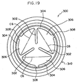
- a plugging sheet 300 as a plugging element which plugs a bottle is shown in Fig. 19 (see Japanese Patent Application Laid-Open (JP-A) No. 8-53147).
- three fan portions 306 are formed from three radial portions 302 which comprise thin portions and three circumferential portions 304 which comprise thin portions. Each of the fan portions 306 is attached to a plugging element 310 by attaching portions 308.
- this plugging sheet 300 is pressed and perforated by a protruding portion of a perforating means which is not shown, since splits are formed from the center of the plugging sheet 300 along the radial portions 302 and then, the splits extend along the circumferential portions 304, respectively, the plugging sheet 300 is opened over the entire cross section of the opening of the bottle.
- This plugging sheet 300 is formed from a high polymer material or a mixture of high polymer materials.
- Three fan portions 306 are formed by three radial portions 302 which have a thickness of between 0.1 and 0.3 mm and by three circumferential portions 304 which have a thickness of between 0.1 and 0.3 mm, similarly to the thickness of the three radial portions 302.
- the fan portions 306 are each attached to a plugging element 310 by the attaching portions 308.
- the thicknesses of the plugging sheet 300 in the areas adjacent to the radial portions 302 and the curcumferential portions 304, each of which has a thickness of between 0.1 mm and 0.3 mm, is close to the thicknesses of the radial portions 302 and the curcumferential portions 304 (if, for example, the thickness of the radial portions 302 and the circumferential portions 304 of 0.3 mm and the thickness of the fan portions 306 is 0.4 mm)
- a portion of the tensional force which is supposed to act upon the radial portion 302 or the circumferential portions 304 due to the pressing force from the perforating means is dispersed and acts upon the fan portions 306. Accordingly, the fan portions 306 are thereby stretched out together with the radial portions 302 or the circumferential portions 304.
- a large amount of pressing force is needed.
- the first aspect of the present invention is a plugging member which plugs a draining port for draining a material which is contained in a container, comprising: a plugging plate body which is mounted in the draining port and is able to plug the draining port; and a thin portion which is formed by decreasing the thickness of the plugging plate body in portions in the thickness direction thereof, using a concave portion which is formed linearly on one end surface of the plugging plate body in the thickness direction thereof and which is formed with a predetermined width or with a width which decreases from the one end surface to the other end surface of the plugging plate body in the thickness direction thereof, wherein the thinnest portion of the thin portion has the thickness T2 which ranges from not less than 0.05 mm to not more than 0.7 mm, the surfaces which face each other and form the concave portion are in parallel with each other, or the angle ⁇ which is formed by the facing surfaces is more than 0° and equal to or less than 120°, and the ratio (L/T2) of the thickness L of the plug
- the draining port In the state in which the plugging member is attached to the draining port, the draining port is plugged by the plugging plate body.
- the substantially central portion of the plugging plate body is pressed by the pressing means such as a bar or the like, the tensional force acts upon portions of the plugging plate body at both sides of each of the thin portions in the direction in which the portions of the plugging plate body are made to separate from each other.
- the ratio (L/T2) of the thickness L of the plugging plate body to the thickness T2 which is the thinnest portion of the thin portion is equal to or more than 2.
- the portion of the plugging plate body on which a concave portion is not formed has a thickness which is equal to or more than a predetermined value.
- the opposite surfaces forming a concave portion are made to be in parallel with each other, or approach to each other so that the angle ⁇ which is formed by the opposite surfaces is more than 0° and is equal to or less than 120°.
- the plugging plate body has a predetermined thickness at both side portions of the thin portion (on which the sloping surfaces are formed).
- the tensional force generated from both side portions of the thin portion is concentrated at the thin portion. Since the thickness T2 of the thinnest portion of the thin portion is equal to or less than 0.7 mm, the plugging plate body is broken along the thin portion by the tensional force which has concentrated at the thin portion.
- the thickness T2 of the thinnest portion of the thin portion is equal to or more than 0.05 mm, and a predetermined strength is secured. Therefore, in the state in which the draining port is plugged by the plugging member, when the pressing force acts upon the plugging member due to an increase in the internal pressure of the container, the plugging plate body does not unexpectedly break.
- Examples of the cross sectional configuration of the concave portion which is formed by decreasing the thickness of the plugging plate body in portions may include: a rectangular shape in which the surfaces facing each other and forming the concave portion are in parallel with each other; a substantially trapezoidal shape in which the opposite surfaces gradually approach to each other toward the other end surface of the plugging plate body; and a substantially V-shape in which the end portions of the opposite surfaces contact with each other.
- the second aspect of the present invention is a plugging member according to the first aspect of the present invention, wherein a low strength portion is formed at the thin portion by decreasing the strength of the thin portion within a predetermined range from the center of the plugging plate body.
- the plugging plate body When the plugging plate body is pressed by the pressing means, firstly, the low strength portion is broken, and then, the broken portion extends to the portion of the plugging plate body other than the low strength portion (outside the predetermined range from the center of the plugging plate body). For this reason, over the entire body of the plugging plate body, the plugging plate body can be broken with an even smaller amount of pressing force as compared to the plugging plate body on which the low strength portion is not formed.
- the plugging plate body is not broken unexpectedly due to the increase of the internal pressure of the container.
- the third aspect of the present invention is a plugging member according to the first aspect of the present invention, wherein three or more of the thin portions are formed, and portions of these thin portions are low strength portions whose strength is made lower than the other thin portions.
- the plugging plate body When the plugging plate body is pressed by the pressing means, the low strength portions are broken, and then, the broken portion extends to the portions of the plugging plate body other than the low strength portions. For this reason, over the entire body of the plugging plate body, the plugging plate body can be broken with a much more smaller amount of pressing force as compared to the plugging plate body on which the low strength portions are not formed.
- the plugging plate body is not broken unexpectedly due to an increase of the internal pressure of the container or the like.
- low strength portion or a plurality of low strength portions can be provided. Further, low strength portions may be formed by applying different strengths to three or more of thin portions.
- the fourth aspect of the present invention is a plugging member according to the third aspect of the present invention, wherein a high strength portion is formed on the thin portions by increasing the strength of the thin portions outside a predetermined range from the center of the plugging plate body.
- the low strength thin portions are broken by the pressing force of the pressing means.
- the breaking is obstructed by the high strength portions which are formed in the low strength thin portions.
- the tensional force acting upon the thin portions by the pressing force of the pressing means extends to the thin portions other than the aforementioned portions (the portions other than the low strength thin portions). Namely, the tensional force due to the pressing force of the pressing means is dispersed to and acts upon a plurality of thin portions (including the low strength thin portion) at different times so that all of the thin portions can be broken.
- the fifth aspect of the present invention is a plugging member according to the first to fourth aspects of the present invention, wherein the plugging plate body is formed in a disc plate shape whose outer diameter R is not less than 0.5 cm and not more than 5 cm.
- the plugging plate body has a predetermined strength, and the thin portion can be broken with a small amount of the pressing force.
- the sixth aspect of the present invention is a plugging member which plugs a draining port for draining a material which is contained in a container, comprising: a plugging plate body which is mounted in the draining port and is able to plug the draining port; and a low strength portion which is formed on the plugging plate body where the strength of the plugging plate body is decreased by a plurality of radial portions which are formed radiating out from substantially the central portion of the plugging plate body toward the external edge thereof, a plurality of curved portions which are formed so as to be curved in an arcuate shape and continue from the tip end of each of the radial portions, and a plurality of circumferential portions which are formed so as to extend from the tip end of each of the curved portions in the direction along the edge of the opening of the draining port.
- the plugging plate body plugs the draining port.
- the pressing means such as a bar or the like
- tensional force acts upon portions of the plugging plate body on both sides of each of the radial portions in the longitudinal direction thereof in the direction in which the portions of the plugging plate body are made to separate from each other, and substantially the central portion of the plugging plate body splits along the radial portions. This split extends to the outer edge of the plugging plate body along the radial portions, and further extends to the circumferential portions by way of the curved portions.
- the plugging plate body Since the circumferential portions are formed in the same direction as the edge of the opening of the draining port, the plugging plate body is broken along the edge of the opening of the draining port at portions where these circumferential portions are formed. For this reason, the plugging plate body is opened wide along the edge of the opening of the draining port.
- the radial portions and the circumferential portions are connected to each other, through the curved portions each of which is curved in an arcuate shape. Accordingly, the radial portions and the circumferential portions are not structured such that they deviate so as to connect to each other. For this reason, even if the pressing force by the pressing means is low, the tensional force, which has acted upon the respective radial portions, also acts upon the respective circumferential portions and the plugging plate body can thereby be broken along the circumferential portions.
- the radial portions are not necessarily formed radiating from the center of the plugging plate body, and instead may be formed radiating from the substantially central portion (at a position slightly displaced from the center) of the plugging plate body provided that the plugging plate body is split along the radial portions by the pressing force from the pressing means.
- the seventh aspect of the present invention is a plugging member according to the sixth aspect of the present invention, wherein the low strength portion is a groove which is formed by decreasing the thickness of the plugging plate body in portions.
- the low strength portion can be formed by a simple structure in which the groove is formed by decreasing the thickness of the plugging plate body in portions.
- the groove of the present invention may be formed by a structure in which the thin portion is formed intermittently at a predetermined distance so as to form as a whole a series of perforation.
- the eighth aspect of the present invention is a container in which a draining port for draining a material contained therein is formed, and the draining port is plugged by the plugging member according to the first to seventh aspects of the present invention.
- the draining port of the container is plugged by the plugging member, the material contained in the container does not leak from the container. Since air or the like does not flow into the container, changes in the characteristics or properties of the material contained therein can be prevented.
- the substantially central portion of the plugging plate body is pressed by the pressing means such as a bar or the like.
- the plugging plate body is opened wide along the edge of the opening of the draining port, and the material contained in the container can be emptied out.
- the ninth aspect of the present invention is a container according to the eighth aspect of the present invention, wherein the container is used for the purpose of containing therein photographic processing chemicals.
- the photographic processing chemicals do not leak from the container, and change in the characteristics or properties of the material contained in the container can be prevented.
- the substantially central portion of the plugging plate body is pressed by a pressing means such as a bar or the like.
- the plugging plate body is opened wide along the edge of the opening of the draining port, and the photographic processing chemicals can be emptied out.
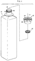
- a packing 10, a cap 12 in which the packing 10 is mounted, and a photographic processing chemicals container 14 (a container for containing a photographic processing chemicals) to which this cap 12 is attached, according to a first embodiment of the present invention are shown in Fig. 1. Further, the cross section of the cap 12 to which the packing 10 is mounted, and the packing 10 are shown in Figs. 2 and 3, respectively.
- the photographic processing chemicals container 14 which is shown in Fig. 1 contains therein photographic processing chemicals, and is an example of a container whose draining port 18 is plugged by the cap 12, in which the packing 10 is mounted, being attached thereto.
- the entire body of this photographic processing chemicals container 14 is formed in a substantially rectangular cylindrical shape, and a cylindrically-shaped portion 16 is formed at one end of the container 14 in the axial direction thereof (at the upper end in Fig. 1).
- One end of the cylindrical portion 16 is used as a draining port 18, and it is possible to drain the photographic processing chemicals which are contained in the photographic processing chemicals container 14 from this draining port 18.
- the cap 12 in which the packing 10 is mounted comprises an attachment cylindrical portion 20 which is formed in a substantially cylindrical shape, and an anchoring cylindrical portion 22 which is formed integrally with one axial end of the attachment cylindrical portion 20 (at the upper end in Fig. 2) and whose diameter is smaller than the attachment cylindrical portion 20.
- a female thread 24 is formed on the internal circumferential surface of the attachment cylindrical portion 20.
- the female thread 24 is screwed onto a male thread 26 (see Fig. 1) which is formed on the external circumferential surface of the cylindrical portion 16 of the photographic processing chemicals container 14. Accordingly, the cap 12 is screwed onto the cylindrical portion 16 and can be attached to the draining port 18.
- An annular ring 28 is formed integrally with the anchoring cylindrical portion 22 at one end in the axial direction thereof (the upper end in Fig. 2) so as to extend toward the inside of the anchoring cylindrical portion 22 in the radial direction.
- a packing mounting portion 32 in which the packing 10 is mounted is formed by the internal surface 22B of the anchoring cylindrical portion 22 and the bottom surface 28B of the ring 28.
- a clearance of a predetermined distance is formed between the external circumferential surface of an insertion cylindrical portion 36 and the internal circumferential surface of the attachment cylindrical portion 20.
- a protruding wall 30 is formed so as to protrude from the top surface 28A of the ring 28 over the entire circumference of the ring 28.
- the cross section of the protruding wall 30 is formed in a substantially triangular shape having a guiding surface 30A and a sloping surface 30C. As seen from the cross section, the guiding surface 30A is parallel with axis J1.
- the sloping surface 30C extends from a protruding tip 30B towards the radial external side of the ring 28 as it approaches the top surface 28A of the ring 28.
- the sloping surface 30C rises toward the radial external side. Accordingly, when a liquid material is contained in the photographic processing chemicals container 14, then even if the draining port 18 faces downward and the material contained in the photographic processing chemicals container 14 flows out due to gravity, the material rises the sloping surface 30C due to surface tension or the like as it empties out and, as a result, the material does not drain in the radial external direction of the photographic processing chemicals container 14.
- the packing 10 is formed from unfoamed resin.
- the resin contains 50% or more of low density polyethylene (LDPE) whose density range is determined to be between 0.910 and 0.929 (g/cm 3 ) in JIS K 6748-1982, or similarly, 50% or more of high density polyethylene (HDPE) whose density range is determined to be equal to or more than 0.942 (g/cm 3 ) in JIS K 6748-10.982.
- LDPE low density polyethylene
- HDPE high density polyethylene
- the packing 10 is formed by the sealing disc portion 34 and the insertion cylindrical portion 36 which are formed integrally with each other.
- the sealing disc portion 34 is formed in a substantially disc shape having a constant thickness L.
- the insertion cylindrical portion 36 is formed in a flattened cylindrical shape and extends perpendicularly to the sealing disc portion 34 from a portion adjacent to the external circumference of the rear surface 34B of the sealing disc portion 34.
- the radial external side portion of the insertion cylindrical portion 36 functions as a flange 38.
- the flange 38 has a constant thickness L, and imparts a predetermined strength to the sealing disc portion 34.
- the outer diameter R of the sealing disc portion 34 ranges from not less than 0.5 cm to not more than 5 cm, and the sealing disc portion 34 has a predetermined strength.
- a plurality of arcuate thin portions 46 are formed on the surface 34A of the sealing disc portion 34 at a predetermined distance from each other in the circumferential direction.
- Circular arc portions 46A of the arcuate thin portions 46 correspond to the internal circumference of the flange 38.
- grooves 50 are formed on the surface 34A of the sealing disc portion 34.
- the grooves 50 are formed by a plurality of radial grooves 52, curved grooves 54, and circumferential grooves 56.
- the plurality of radial grooves 52 (four in the present embodiment) extend linearly from the center of the surface 34A of the sealing disc portion 34 toward the external circumference of the sealing disc portion 34 (toward the center of each of the arcuate thin portions 46).
- Each of the curved grooves 54 continues on from the extending end 52A of each of the radial grooves 52 and curves in a smooth circular arc without deviation in the same direction and at a constant angle of curvature with the same central angle.
- Each of the circumferential grooves 56 extends without deviation from the tip end of each of the curved grooves 54 along the external circumference of the sealing disc portion 34 so as to form a smooth circular arc shape.
- a portion between the grooves 50 adjacent to each other is a fan portion 58 which is formed in a substantially fan shape having a thickness L which is the same as the flange 38.
- each of the grooves 50 is cut diagonally from the surface 34A to the rear surface 34B of the sealing disc portion 34 so as to form a substantially V-shaped cross section having a pair of sloping surfaces 60.
- the angle ⁇ formed by the sloping surfaces 60 has a predetermined angle which is more than 0° and equal to or less than 120°.
- the distance between the sloping surfaces 60 gradually decreases from the surface 34A to the rear surface 34B, of the sealing disc portion 34.
- each of the radial grooves 52 has a predetermined length such that the tip end 52A of the radial groove 52 does not extend to the arcuate thin portion 46 (i.e., the length of the radial groove portion 52 is smaller than the radius of the sealing disc portion 34). More specifically if the internal circumference of the flange 38 (a circle which is formed by the circular arc portions 46A of the arcuate thin portions 46) is R1, then preferably, 0 ⁇ L1 ⁇ (4/5) ⁇ R1 from a standpoint of perforation performance (splittability of the groove 50) which will be described later, and more preferably, (1/5) ⁇ R1 ⁇ L1 ⁇ (2/3) ⁇ R1.
- a low strength portion 64 is formed on each of the radial grooves 52 within a predetermined range from the center of the sealing disc portion 34 (within the range indicated by a double-dashed line C1 in Fig. 4A), by not changing the width W of the upper end of the radial groove 52 (see Figs. 7A and 7B), but by deeply cutting the radial groove 52 (accordingly, the inclination angle ⁇ formed by the sloping surfaces 60 is made smaller) thus further decreasing the thickness of the thin portion 62 (thickness T2).
- the thickness T2 of the low strength portion 64 is set to range from not less than 0.05 mm to not more than 0.7 mm. Further, the thickness T2 is set such that the ratio of the plate thickness L of the sealing disc portion 34 to the thickness T2 of the low strength portion 64 (L/T2) is 2 or more.
- the curved grooves 54 are curved in a circular arc shape, continuing on from the tip ends 52A of the radial grooves 52 in the same direction (in the clockwise direction in Fig. 4A in the present embodiment), at a predetermined radius of curvature R2, and at a predetermined central angle.
- Each of the curved grooves 54 contacts with a chord portion 46B (a straight line portion) of each of the arcuate thin portions 46, and gradually extends toward the external circumference of the sealing disc portions 34.
- the curved groove 54 is thought of as being divided into micro portions, in these micro portions, it is not necessary to maintain the radius of curvature R2 constant.
- the respective micro portions may have different radii of curvature R2 or a portion thereof may be formed by a straight line connecting internal portions of the arc provided that the smoothness of the curved groove 54 as a whole is not lost.
- the strength of the thin portion 62 of each of the curved grooves 54 is made to be much lower at a portion of the sealing disc portion 34 outside a predetermined range from the center of the sealing disc portion 34 (outside the range indicated by the double-dashed line C2 in Fig. 4A) without changing the width W of the upper end of the curved groove 54, by deeply cutting the curved groove 54 and thereby decreasing the thickness of the thin portion 62 (thickness T2).
- Either one of the pair of sloping surfaces 60 which are shown in Figs. 7A and 7B is not formed at a portion at which the curved groove 54 is formed along the chord portion 46B of the arcuate thin portion 46. However, in this portion also, the thickness of the arcuate thin portion 46 is T2 so that, essentially, the curved groove 54 is formed.
- the circumferential grooves 56 extend from the respective tip ends of the curved grooves 54 along the external circumference of the sealing disc portion 34.
- the circumferential grooves 56 are different from the radial grooves 52 and the curved grooves 54 in that each of the circumferential grooves 56 is formed by a single sloping surface 60 extending from the surface 34A to the rear surface 34B of the sealing disc portion 34, and by a vertical surface portion 46C which forms the circular arcuate portion 46A of the arcuate thin portion 46.
- the thin portions 62 having the same thickness T2 as the arcuate thin portions 46 are formed by the circumferential grooves 56. Accordingly, as can be seen from an overall view of the grooves 50 in Figs.
- the low strength portion 64 in which the thickness of the thin portion 62 is decreases even further is formed within the range from the center of the sealing disc portion 34 to the double-dashed line C1.
- the thickness of the thin portion 62 is not decreased any more (thickness T3) so that a constant strength can be maintained.
- the thickness of the thin portion 62 is decreased once more (thickness T2).
- a photographic processing chemicals supplying device 70 in the automatic developer is schematically shown in Fig. 8.
- the photographic processing chemicals container 14 is set in the photographic processing chemicals supplying device 70, the photographic processing chemicals are supplied from the container 14.
- the photographic processing chemicals container 14 is inserted into a holding hole 74 of a holding plate 72 and set upside down.
- the photographic processing chemicals container 14 is held above a replenishing tank (not shown) in a state where the draining port 18 (see Fig. 1) faces downward.
- the draining port 18 of the photographic processing chemicals container 14 is plugged by the packing 10, the photographic processing chemicals does not flow out inadvertently from the photographic processing chemicals container 14.
- the upper end of a perforating pipe 76 which is provided in the photographic processing chemicals supplying device 70 is positioned beneath the packing 10 plugging the draining port 18.
- an unillustrated controller rotates a pinion inside a driving portion 78 and raises an elevating portion 80.
- the perforating pipe 76 extending from the elevating portion 80 is thereby raised, and the tip end of the perforating pipe 76 pushes up the central portion of the packing 10 which plugs the draining port 18.
- the maximum amount of pressing force (perforation force) is needed at the initial stage of the pressing, i.e., immediately before and after perforation starts.
- the sealing disc portion 34 can be broken along the radial grooves 52. Namely, the thin portions 62 in the vicinity of the central portion of the sealing disc portion 34 can be split with a small amount of pressing force. Accordingly, the sealing disc portion 34 can be broken along the thin portions 62.
- the splits when the perforating pipe 76 is further raised, the splits extend to the external side of the sealing disc portion 34 in the radial direction thereof, and further extend to the thin portions 62 which are formed by the curved grooves 54 (see Fig. 4A). During this splitting process, the splits extend from the low strength portion 64 to a portion of the thin portion 62 at which the low strength portion 64 is not formed (within the range between the double-dashed line C1 and the double-dashed line C2 in Fig. 4A). However, at this time, since splits have already been formed on the sealing disc portion 34, these splits can be expanded with a small amount of pressing force.
- the thickness of a portion of each of the thin portions 62 outside the range indicated by the double-dashed line C2 in Fig. 4A is decreased again (thickness T2), and the strength thereof is made low.
- the sealing disc portion 34 is broken with a smaller amount of pressing force.
- the splits extend to the chord portions 46B of the arcuate thin portions 46, only the fan portion 58 on one side of each of the thin portions 62 is pulled away from the arcuate thin portion 46.
- the splits expand along the low strength portions of the thin portions 62 which are formed by the curved grooves 54, and extend to the thin portions 62 which are formed by the circumferential grooves 56.
- each of the fan portions 58 is thereby bent at the chord portion 46B of the arcuate thin portion 46.
- the sealing disc portion 34 is opened and the area of the opening is made wider (in contrast to this, for example, when the circumferential groove 56 is not formed on the sealing disc portion 34, since the fan portion 58 is bent along the line indicated by the double-dashed line C3 which is shown in Fig. 4A, the area of the opening of the sealing disc portion 34 is made narrower).
- curved grooves 54 which continue on smoothly without deviation from the radial grooves 52, and circumferential grooves 56, which continue on smoothly without deviation from the curved grooves 54 along the external circumference of the sealing disc portion 34, are formed on the sealing disc portion 34 for plugging the draining port 18 of the photographic processing chemicals container 14.
- the sealing disc portion 34 can be opened wide with a small amount of pressing force.
- the low strength portions 64 are formed at portions within a predetermined range from the center thereof (within the range indicated by the double-dashed line C1 which is shown in Fig. 4A) of the thin portions 62 which are formed on the sealing disc portion 34 as compared to the packing in which the strength of these portions is not reduced, the sealing disc plate 34 is broken with a smaller amount of pressing force, and the draining port 18 of the photographic processing chemicals container 14 can thereby be opened.
- the sealing disc portion 34 maintains a constant strength. Accordingly, due to, for example, a change or the like of the internal pressure of the photographic processing chemicals container 14, even if the sealing disc portion 34 is pressed outwardly or inwardly of the photographic processing chemicals container 14, the sealing disc portion 34 is not broken unexpectedly. Especially when the photographic processing chemicals container 14 is dropped, the internal pressure of the container 14 may increase temporarily, however, even in this case, the sealing disc portion 34 is not broken.
- the sealing disc portion 34 since the outer diameter of the sealing disc portion 34 is between not less than 0.5 cm and not more than 5 cm, the sealing disc portion 34 stretches appropriately due to pressing force from the pressing means (however, it does not stretch excessively), the sealing disc portion 34 can be broken with a small amount of pressing force.
- opposing properties can be realized, namely, that a predetermined amount of strength is maintained in the sealing disc portion 34, and the pressing force which is needed by the pressing means to perforate this sealing disc portion 34 (i.e., the perforating force of the perforating pipe 76) can be minimized.
- a packing 110 according to the second embodiment of the present invention is shown in Fig. 14.
- this packing 110 only the configuration of grooves in the second embodiment of the present invention is different as compared to the packing 10 according to the first embodiment of the present invention.
- Structural parts and members identical to those of the packing 10 according to the first embodiment are denoted by the same reference numerals, and a description thereof will be omitted.
- the thickness of each of the two thin portions 114A and 114B is smaller than that of each of the other two thin portions 114C and 114D.
- the thin portions 114A and 114B are low strength thin portions having a strength which is lower than the other thin portions 114C and 114D.
- Fig. 15A the relationship which is shown in Fig. 15A exists between the length of a split which is formed by the sealing disc portion 116 being pressed by the pressing means (the perforating pipe 76), and the pressing force which is generated by the pressing means and is needed to expand the split.
- the relationship between the distance moved (on the basis of the distance moved from the tip end of the perforating pipe 76 at the point the tip end contacts with the sealing disc portion) and the pressing force of the perforating pipe 76 is shown in the graph in Fig. 15A.
- the pressing force amounts to its maximum value F1 (which is referred to as maximum pressing force, hereinafter).
- F1 which is referred to as maximum pressing force, hereinafter.
- splits are formed at the thin portions. Once splits are formed on the sealing disc portion 34, only a small amount of pressing force is needed in order to expand the splits. Accordingly, after the pressing force has exceeded the maximum pressing force F1, the pressing force decreases invariably.
- Fig. 15B the relationship between the distance moved and the pressing force of the perforating pipe 76 when a sealing disc portion 116 of the packing 110 is pressed and broken by the perforating pipe 76 is shown in Fig. 15B.
- the maximum pressing force F2 which is needed to form splits at the thin portions 114A and 114B, is less than the maximum pressing force F1 which is shown in Fig. 15A.
- the pressing force acts upon and is dispersed at the four thin portions 114A, 114B, 114C and 114D at different times.
- the tensional force which acts upon the fan portions 58 adjacent to each other by the pressing force of the pressing means can be dispersed at different times. Accordingly, the sealing disc portion 116 can be broken with a small amount of pressing force. Further, splits can be first induced at the thin portions 114A and 114B by making the thin portions 114A and 114B low strength portions.
- the thickness of the other thin portions 114C and 114D can be made relatively larger, it is possible to make the thickness of all four thin portions 114A, 114B, 114C and 114D larger. For this reason, the strength of the sealing disc portion 116 can be kept constant and even when the sealing disc portion 116 is pressed inwardly or outwardly of the photographic processing chemicals container 14, the sealing disc portion 116 does not unexpectedly break.
- the strength of one thin portion or three or more of the thin portions may be made to be lower than the other thin portions.
- the above-described effect which is obtained by forming low strength thin portions can be accomplished.
- high strength portions 118 where the thickness of the thin portions 114A, 114B, 114C, and 114D has been increased can be formed outside a predetermined range from the center of the sealing disc portion 116 (outside the range indicated by the double-dashed line C4 in Fig. 14A) by increasing the angle ⁇ (refer to Figs. 7A and 7B) which is formed by the sloping surfaces 60.
- ⁇ the angle which are formed at the thin portions 114A and 114B are prevented from extending any more, and thereafter, the thin portions 114C and 114D which are not formed as low strength portions begin to split.
- the four thin portions 114A, 114B, 114C, and 114D are caused to split at the same time, and the sealing disc portion 116 is thereby broken.
- the thickness of the thin portions 114A and 114B is made larger (thickness T4) by increasing the angle ⁇ which is formed by the sloping surfaces 60 (see Figs. 7A and 7B).
- the strength of each of the thin portions 114A, 114B, 114C, and 114D is increased so that high strength portions 120 can be formed.
- the splits can extend with a small amount of pressing force, and the sealing disc portion 116 can be broken.
- a packing 130 as an another example is shown in Figs. 17A and 17B.
- this packing 130 within a predetermined range from the center of a sealing disc portion 132 (within the range indicated by the double-dashed line C5), the thickness of each of thin portions 136 which are formed by grooves 134 is made larger in portions by increasing the angle ⁇ which is formed by the sloping surfaces 60 (see Figs. 7A and 7B), and the strength thereof thereby increases. For this reason; as compared, for example, to the packing 10 according to the first embodiment of the present invention, at the initial stage of perforating the sealing disc portion 132, it is necessary to press the sealing disc portion 132 with a larger amount of pressing force.
- the tip ends of the splits extend to the range of the sealing disc portion 132 outside the range indicated by the double-dashed line C5
- the splits extend to the outside of the sealing disc portion 132 in the radial direction thereof with an extremely small amount of pressing force, and the sealing disc portion 132 can be opened.
- Fig. 18A an example in which the sloping surfaces 60 which form the grooves 50, 112, and 134 contact with each other at their bottom ends, and the cross sectional view of each of the grooves 50, 112, and 134 is formed in a substantially V-shape has been described.
- the configurations of the grooves 50, 112, and 134 are not limited to this.
- they can be formed in a substantially trapezoidal configuration in which the bottom ends 60A of the sloping surfaces 60 do not contact with each other and are separated from each other.
- a flat portion 66 which is parallel with the rear surface 34B of the sealing disc portion 34 is formed between the bottom ends 60A of the sloping surfaces 60.
- a curved portion may be formed which is curved so as to form a concave shape protruding towards the rear surface 34B, between the bottom ends 60A of the sloping surfaces 60.
- the sloping surfaces 60 may be formed perpendicular to the top surface 34A and the rear surface 34B, of the sealing disc portion 34 (therefore, in actual fact, the sloping surfaces 60 do not slope) in a rectangular shape having a flat portion 66 between the bottom ends of the sloping surfaces 60.
- the structure in which the thin portions 62, 114, and 136 have low strength or high strength partially or locally an example of the structure in which the thicknesses of the thin portions 62, 114, and 136 are increased or decreased by changing the angle ⁇ which is formed by the sloping surfaces 60 has been explained.
- the structure in which each of the thin portions 62, 114, and 136 has low strength or high strength partially or locally is not limited to this.
- each of the thin portions 62, 114 and 136 has the flat portion 66 having a predetermined width
- the width of the flat portion 66 of each of the thin portions 62, 114 and 136 is made narrower (including the sloping surfaces 60 without a flat portion 66 therebetween, as is shown in Fig. 18A), the tensional force is concentrated within this narrow range.
- the elongation of the thin portions 62 as a whole in the tensional direction decreases, and the thin portions 62 split easily.
- the width of the flat portion 66 is made wider, since the tensional force is dispersed within this wider range, the elongation of the thin portions 62 as a whole in the tensional direction increases, and the thin portions 62 do not split easily.
- the thin portions 62, 114, and 136 do not necessarily have low strength or high strength partially or locally and instead may have constant strength (thickness T2 or T4) from the center of the sealing disc portion 34 to the outer circumference thereof. Namely, even in this case, provided that the curved grooves 54 which continue in a smooth without deviation from the extending ends 52A of the radial grooves 52 are formed and, provided that the circumferential grooves 56 which continue in a smooth arcuate shape without deviation from the curved grooves 54 along the outer circumference of the sealing disc portion 34 are formed, the sealing disc portion 34 can be opened wide with a small amount of pressing force.
- the thin portions 62, 114 and 136 may have a constant strength (constant thickness T4). Namely, even in this case, in the same manner that the ratio (L/T2) of the thickness L of the sealing disc portion 34 to the thickness T2 of the low strength portion 64 is set to be equal to or more than 2, (L/T4) is set to be equal to or more than 2, and the sealing disc portion 34 can thereby be opened wide with a small amount of pressing force.
- each of the grooves 50, 112 and 134 is not limited to the above-described number of four. However, even if the pressing force is weak, in order to open the sealing disc portion 34, 116 and 132 widely, the number of grooves is preferably three to five, and more preferably four. Conversely, if the number of the grooves 50, 112, and 134 is six or more, after the opening, the fan portions 58 (see Fig. 4A) of each of the sealing disc portions 34, 116 and 132 contact closely with the pressing means (the perforating pipe 76), and a clearance which is formed between each of the fan portions 58 and the pressing means decreases.
- the grooves 50, 112, and 134 are two or less, it becomes difficult to substantially open the sealing disc portions 34, 116, and 132.
- the grooves can be structured as if the number of the grooves 50, 112 and 134, respectively, were three to five, by curving the grooves so as to be formed in a suitable configuration. If three to five grooves are formed, they don't need to be formed radiating from the center of each of the sealing disc portions 34, 116, and 132 at a fixed central angle.
- the grooves 50, 112, and 134 do not need to be formed in a continuous linear shape and, for example, may be formed intermittently at predetermined distances in the longitudinal direction thereof so as to form, as a whole, a series of perforations.
- the low strength portions according to the present invention are not limited to the grooves 50, 112 and 134 or grooves which are formed in a perforated shape.
- a portion which may be split by the pressing force of the pressing means, can be formed by changing the physical properties of the sealing portions 34, 116 and 132.
- An example of this is the weld line.
- a weId line is formed during injection molding of a resin molded product when resin which has flowed out of the gate and diffused around the gate rebonds inside the die. Namely, at portions where a weld line is formed, in many cases, the strength of the resin is deteriorated. Accordingly, molding conditions, the position of the gate, or the like should be set appropriately so that weld lines are formed in the same shape as the thin portions when seen in a plan view.
- the sealing disc portion can be broken along a weld line simply by forming the weld line, however, by further forming the grooves 50, 112 and 134 at the portions where weld lines are formed, it is possible to form a packing which can open with a smaller amount of pressing force.
- each of the packings 10, 110 and 130 is formed separately from the cap 12
- the respective packings 10, 110 and 130 may be integrated with and the cap 12. In this way, when each of the packings 10, 110 and 130 are integrated with the cap 12 and, each of the packings 10, 110 and 130 does not fall from the cap 12.
- photographic processing chemicals contained in the photographic processing chemicals container 14 for example, a color developing solution, a black & white developing solution, a bleaching solution, a fixing solution, or the like can be listed. These photographic processing chemicals are used to treat a halogen silver photosensitive material, are commercially available, and are known.
- unfoamed resin which contains 50% or more of low density polyethylene (LDPE) or 50% or more of high density polyethylene (HDPE) has been listed.
- LDPE low density polyethylene
- HDPE high density polyethylene
- the present invention is not limited to this and instead, materials are appropriately determined by taking chemical resistance, physical strength, or the like of the materials to be contained in the container into consideration.
- polyethylene is listed as one of the preferable materials.
- the packing is formed from a resin material which contains a large amount of low density polyethylene (LDPE), as compared to when the packing is formed from a resin material which contains high density polyethylene (HDPE), because the resin itself is soft, the packing is apt to elongate. Accordingly, the central portion of each of the sealing disc portions 34, 116, and 132 can be broken with a low pressing force. Further, due to the softness of the resin itself, when the distance moved by the perforating pipe 76 is short, it is possible that the central portions of the sealing disc portions 34, 116 and 132 are in an elongated state but are not broken.
- LDPE low density polyethylene
- HDPE high density polyethylene
- the packings 10, 110 and 130 are formed from a resin material which contains a large amount of high density polyethylene (HDPE), as compared to when the packings 10, 110, and 130 are formed from a resin material which contains a large amount of low density polyethylene (LDPE), the resin itself is hard. Accordingly, at the initial stage of breaking the sealing disc portions 34, 116 and 132, a larger amount of pressing force is needed. However, once splits are formed on the sealing disc portions 34, 116, and 132 (the sealing disc portions 34, 116, and 132 are broken), the entire body of each of the sealing disc portions 34, 116, and 132 deforms, and perforating force (tensional force) acts upon the thin portions 62 which are structured by the grooves 50.
- HDPE high density polyethylene
- LDPE low density polyethylene
- the above-described conditions may be realized by using a resin which contains a large amount of middle density polyethylene (MDPE) having a density range of between 0.930 and 0.941 (g/cm 3 ) in JIS K 6748-1982.
- MDPE middle density polyethylene
- a method of opening the packing 10, 110, and 130 is not limited to the case in which the photographic processing chemicals container 14 is set in the photographic processing chemicals supplying device 70 (see Fig. 8) in an automatic developer, and the packing 10 is pressed by the perforating pipe 76.
- the packings 10, 110 and 130 can be pressed by a bar or the like and thereby opened.
Abstract
Description
- The present invention relates to a plugging member and a container, and more particularly to a plugging member which plugs a draining port for draining a material which is contained in a container, and the container. For example, the plugging member is used to plug a draining port of a photographic processing chemicals container which contains therein photographic processing chemicals.
- As an example of a conventional plugging member, a
plugging sheet 300 as a plugging element which plugs a bottle is shown in Fig. 19 (see Japanese Patent Application Laid-Open (JP-A) No. 8-53147). - In this
plugging sheet 300, threefan portions 306 are formed from threeradial portions 302 which comprise thin portions and threecircumferential portions 304 which comprise thin portions. Each of thefan portions 306 is attached to aplugging element 310 by attachingportions 308. - When this
plugging sheet 300 is pressed and perforated by a protruding portion of a perforating means which is not shown, since splits are formed from the center of theplugging sheet 300 along theradial portions 302 and then, the splits extend along thecircumferential portions 304, respectively, theplugging sheet 300 is opened over the entire cross section of the opening of the bottle. - However, in this
plugging sheet 300, since the thin portions are curved at a small radius of curvature from theradial portions 302 to thecircumferential portions 304, there may be cases in which the force which has acted upon theradial portions 302 does not extend to thecircumferential portions 304. For this reason, when the amount of pressing force excited by the perforating means is small, the splits do not extend from the tip ends of theradial portions 302 to thecircumferential portions 304, and thefan portions 306 are bent at positions indicated by a dashed line C6 in Fig. 19. Accordingly, it is impossible to open theplugging sheet 300 over the entire cross section of the opening of the bottle. As a result, the surface area of the opening is made narrower. - This
plugging sheet 300 is formed from a high polymer material or a mixture of high polymer materials. Threefan portions 306 are formed by threeradial portions 302 which have a thickness of between 0.1 and 0.3 mm and by threecircumferential portions 304 which have a thickness of between 0.1 and 0.3 mm, similarly to the thickness of the threeradial portions 302. Thefan portions 306 are each attached to aplugging element 310 by the attachingportions 308. - When this
plugging sheet 300 is pressed and perforated by the protruding portion of a perforating means which is not shown, since splits extend from the center of theplugging sheet 300 along theradial portions 302, and then extend along thecircumferential portions 304, theplugging sheet 300 is opened over the entire cross section of the opening of the bottle. - However, in this
plugging sheet 300, if the thicknesses of theplugging sheet 300 in the areas adjacent to theradial portions 302 and thecurcumferential portions 304, each of which has a thickness of between 0.1 mm and 0.3 mm, is close to the thicknesses of theradial portions 302 and the curcumferential portions 304 (if, for example, the thickness of theradial portions 302 and thecircumferential portions 304 of 0.3 mm and the thickness of thefan portions 306 is 0.4 mm), a portion of the tensional force which is supposed to act upon theradial portion 302 or thecircumferential portions 304 due to the pressing force from the perforating means is dispersed and acts upon thefan portions 306. Accordingly, thefan portions 306 are thereby stretched out together with theradial portions 302 or thecircumferential portions 304. As a result, in order to perforate theplugging sheet 300, a large amount of pressing force is needed. - In view of the aforementioned facts, it is an object of the present invention to obtain a plugging member which can open a draining port wide with a low pressing force, and a container whose draining port is plugged by this plugging member.
- The first aspect of the present invention is a plugging member which plugs a draining port for draining a material which is contained in a container, comprising: a plugging plate body which is mounted in the draining port and is able to plug the draining port; and a thin portion which is formed by decreasing the thickness of the plugging plate body in portions in the thickness direction thereof, using a concave portion which is formed linearly on one end surface of the plugging plate body in the thickness direction thereof and which is formed with a predetermined width or with a width which decreases from the one end surface to the other end surface of the plugging plate body in the thickness direction thereof, wherein the thinnest portion of the thin portion has the thickness T2 which ranges from not less than 0.05 mm to not more than 0.7 mm, the surfaces which face each other and form the concave portion are in parallel with each other, or the angle which is formed by the facing surfaces is more than 0° and equal to or less than 120°, and the ratio (L/T2) of the thickness L of the plugging plate body to the thickness T2 is equal to or more than 2.
- In the state in which the plugging member is attached to the draining port, the draining port is plugged by the plugging plate body. In this state, when the substantially central portion of the plugging plate body is pressed by the pressing means such as a bar or the like, the tensional force acts upon portions of the plugging plate body at both sides of each of the thin portions in the direction in which the portions of the plugging plate body are made to separate from each other.
- The ratio (L/T2) of the thickness L of the plugging plate body to the thickness T2 which is the thinnest portion of the thin portion is equal to or more than 2. As compared to the thin portion, the portion of the plugging plate body on which a concave portion is not formed has a thickness which is equal to or more than a predetermined value. The opposite surfaces forming a concave portion are made to be in parallel with each other, or approach to each other so that the angle Θ which is formed by the opposite surfaces is more than 0° and is equal to or less than 120°. The plugging plate body has a predetermined thickness at both side portions of the thin portion (on which the sloping surfaces are formed). For this reason, the tensional force generated from both side portions of the thin portion is concentrated at the thin portion. Since the thickness T2 of the thinnest portion of the thin portion is equal to or less than 0.7 mm, the plugging plate body is broken along the thin portion by the tensional force which has concentrated at the thin portion.
- The thickness T2 of the thinnest portion of the thin portion is equal to or more than 0.05 mm, and a predetermined strength is secured. Therefore, in the state in which the draining port is plugged by the plugging member, when the pressing force acts upon the plugging member due to an increase in the internal pressure of the container, the plugging plate body does not unexpectedly break.
- Examples of the cross sectional configuration of the concave portion which is formed by decreasing the thickness of the plugging plate body in portions may include: a rectangular shape in which the surfaces facing each other and forming the concave portion are in parallel with each other; a substantially trapezoidal shape in which the opposite surfaces gradually approach to each other toward the other end surface of the plugging plate body; and a substantially V-shape in which the end portions of the opposite surfaces contact with each other.
- The second aspect of the present invention is a plugging member according to the first aspect of the present invention, wherein a low strength portion is formed at the thin portion by decreasing the strength of the thin portion within a predetermined range from the center of the plugging plate body.
- When the plugging plate body is pressed by the pressing means, firstly, the low strength portion is broken, and then, the broken portion extends to the portion of the plugging plate body other than the low strength portion (outside the predetermined range from the center of the plugging plate body). For this reason, over the entire body of the plugging plate body, the plugging plate body can be broken with an even smaller amount of pressing force as compared to the plugging plate body on which the low strength portion is not formed.
- In the thin portion other than the low strength portion, since the thin portion has a strength which is higher than the low strength portion, for example, the plugging plate body is not broken unexpectedly due to the increase of the internal pressure of the container.
- The third aspect of the present invention is a plugging member according to the first aspect of the present invention, wherein three or more of the thin portions are formed, and portions of these thin portions are low strength portions whose strength is made lower than the other thin portions.
- When the plugging plate body is pressed by the pressing means, the low strength portions are broken, and then, the broken portion extends to the portions of the plugging plate body other than the low strength portions. For this reason, over the entire body of the plugging plate body, the plugging plate body can be broken with a much more smaller amount of pressing force as compared to the plugging plate body on which the low strength portions are not formed.
- Since the thin portions other than the low strength portions have a strength which is higher than the low strength portions, for example, the plugging plate body is not broken unexpectedly due to an increase of the internal pressure of the container or the like.
- One low strength portion or a plurality of low strength portions can be provided. Further, low strength portions may be formed by applying different strengths to three or more of thin portions.
- The fourth aspect of the present invention is a plugging member according to the third aspect of the present invention, wherein a high strength portion is formed on the thin portions by increasing the strength of the thin portions outside a predetermined range from the center of the plugging plate body.
- Firstly, the low strength thin portions are broken by the pressing force of the pressing means. However, the breaking is obstructed by the high strength portions which are formed in the low strength thin portions. The tensional force acting upon the thin portions by the pressing force of the pressing means extends to the thin portions other than the aforementioned portions (the portions other than the low strength thin portions). Namely, the tensional force due to the pressing force of the pressing means is dispersed to and acts upon a plurality of thin portions (including the low strength thin portion) at different times so that all of the thin portions can be broken.
- The fifth aspect of the present invention is a plugging member according to the first to fourth aspects of the present invention, wherein the plugging plate body is formed in a disc plate shape whose outer diameter R is not less than 0.5 cm and not more than 5 cm.
- Accordingly, the plugging plate body has a predetermined strength, and the thin portion can be broken with a small amount of the pressing force.
- The sixth aspect of the present invention is a plugging member which plugs a draining port for draining a material which is contained in a container, comprising: a plugging plate body which is mounted in the draining port and is able to plug the draining port; and a low strength portion which is formed on the plugging plate body where the strength of the plugging plate body is decreased by a plurality of radial portions which are formed radiating out from substantially the central portion of the plugging plate body toward the external edge thereof, a plurality of curved portions which are formed so as to be curved in an arcuate shape and continue from the tip end of each of the radial portions, and a plurality of circumferential portions which are formed so as to extend from the tip end of each of the curved portions in the direction along the edge of the opening of the draining port.
- In the state in which the plugging member is mounted in the draining port, the plugging plate body plugs the draining port. In this state, when substantially the central portion of the plugging plate body is pressed by the pressing means such as a bar or the like, then at substantially the central portion of the plugging plate body, tensional force acts upon portions of the plugging plate body on both sides of each of the radial portions in the longitudinal direction thereof in the direction in which the portions of the plugging plate body are made to separate from each other, and substantially the central portion of the plugging plate body splits along the radial portions. This split extends to the outer edge of the plugging plate body along the radial portions, and further extends to the circumferential portions by way of the curved portions.
- Since the circumferential portions are formed in the same direction as the edge of the opening of the draining port, the plugging plate body is broken along the edge of the opening of the draining port at portions where these circumferential portions are formed. For this reason, the plugging plate body is opened wide along the edge of the opening of the draining port.
- Further, the radial portions and the circumferential portions are connected to each other, through the curved portions each of which is curved in an arcuate shape. Accordingly, the radial portions and the circumferential portions are not structured such that they deviate so as to connect to each other. For this reason, even if the pressing force by the pressing means is low, the tensional force, which has acted upon the respective radial portions, also acts upon the respective circumferential portions and the plugging plate body can thereby be broken along the circumferential portions.
- The radial portions are not necessarily formed radiating from the center of the plugging plate body, and instead may be formed radiating from the substantially central portion (at a position slightly displaced from the center) of the plugging plate body provided that the plugging plate body is split along the radial portions by the pressing force from the pressing means.
- The seventh aspect of the present invention is a plugging member according to the sixth aspect of the present invention, wherein the low strength portion is a groove which is formed by decreasing the thickness of the plugging plate body in portions.
- By forming a groove on the plugging plate body, the cross sectional area of the plugging plate body in the groove portion decreases. Accordingly, the tensional force is concentrated in the groove portion, and the plugging plate body is broken along the groove. In this way, the low strength portion can be formed by a simple structure in which the groove is formed by decreasing the thickness of the plugging plate body in portions.
- Other than the structure in which the thin portion is formed so as to be in continuous, the groove of the present invention may be formed by a structure in which the thin portion is formed intermittently at a predetermined distance so as to form as a whole a series of perforation.
- The eighth aspect of the present invention is a container in which a draining port for draining a material contained therein is formed, and the draining port is plugged by the plugging member according to the first to seventh aspects of the present invention.
- Because the draining port of the container is plugged by the plugging member, the material contained in the container does not leak from the container. Since air or the like does not flow into the container, changes in the characteristics or properties of the material contained therein can be prevented.
- In the state in which the plugging member is attached to the draining port, namely, without detaching the plugging member from the draining port, the substantially central portion of the plugging plate body is pressed by the pressing means such as a bar or the like. The plugging plate body is opened wide along the edge of the opening of the draining port, and the material contained in the container can be emptied out.
- The ninth aspect of the present invention is a container according to the eighth aspect of the present invention, wherein the container is used for the purpose of containing therein photographic processing chemicals.
- The photographic processing chemicals do not leak from the container, and change in the characteristics or properties of the material contained in the container can be prevented.
- In the state in which the plugging member is attached to the draining port, the substantially central portion of the plugging plate body is pressed by a pressing means such as a bar or the like. The plugging plate body is opened wide along the edge of the opening of the draining port, and the photographic processing chemicals can be emptied out.
-
- Fig. 1 is an exploded perspective view illustrating a packing according to a first embodiment of the present invention, a cap in which this packing is mounted, and a container to which the cap is attached.
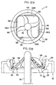
- Fig. 2 is a cross sectional view illustrating a state in which the packing according to the first embodiment of the present invention is mounted in the cap.
- Fig. 3 is a perspective view illustrating the packing according to the first embodiment of the present invention.
- Fig. 4A is a plan view illustrating the packing according to the first embodiment of the present invention.
- Fig. 4B is a cross sectional view taken along the line IV-IV in Fig. 4A and illustrates the packing according to the first embodiment of the present invention.
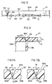
- Fig. 5 is a cross sectional view taken along the line V-V in Fig. 4A and illustrates the packing according to the first embodiment of the present invention.
- Fig. 6 is a cross sectional view taken along the line VI-VI in Fig. 4A and illustrates the packing according to the first embodiment of the present invention.
- Fig. 7A is a cross sectional view taken along the line VII-VII in Fig. 4A and illustrates the packing according to the first embodiment of the present invention.
- Fig. 7B is a cross sectional view taken along the line VIII-VIII in Fig. 4A and illustrates the packing according to the first embodiment of the present invention.
- Fig. 8 is a perspective view illustrating a schematic structure of photographic processing chemicals supplying device which supplies photographic processing chemicals from the container whose draining port is plugged by the packing according to the first embodiment of the present invention.
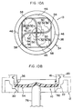
- Fig. 9A is a plan view of the packing and illustrates the vicinity thereof in the state in which the container is set in the photographic processing chemicals supplying device which is shown in Fig. 8.
- Fig. 9B is a cross sectional view of the packing and illustrates the vicinity thereof in the state in which the container is set in the photographic processing chemicals supplying device which is shown in Fig. 8.
- Fig. 10A is a plan view of the packing and illustrates a state during the breaking of the packing by the photographic processing chemicals supplying device which is shown in Fig. 8.
- Fig. 10B is a cross sectional view of the packing and illustrates a state during the breaking of the packing by the photographic processing chemicals supplying device which is shown in Fig. 8.
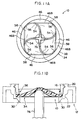
- Fig. 11A is a plan view of the packing and illustrates a state during the breaking of the packing by the photographic processing chemicals supplying device which is shown in Fig. 8.
- Fig. 11B is a cross sectional view of the packing and illustrates a state during the breaking of the packing by the photographic processing chemicals supplying device which is shown in Fig.8.
- Fig. 12A is a plan view of the packing and illustrates a state in which the packing is broken by the photographic processing chemicals supplying device which is shown in Fig. 8.
- Fig. 12B is a cross sectional view of the packing and illustrates a state in which the packing is broken by the photographic processing chemicals supplying device which is shown in Fig. 8.
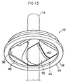
- Fig. 13 is a perspective view illustrating a state in which the packing is broken by the photographic processing chemicals supplying device which is shown in Fig. 8.
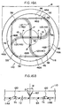
- Fig. 14A is a plan view which illustrates a packing according to a second embodiment of the present invention.
- Fig. 14B is a cross sectional view taken along the line XIV-XIV in Fig. 14A and illustrates the packing according to the second embodiment of the present invention.
- Fig. 15A is a graph illustrating the relationship between the moving distance and the pressing force of a perforating pipe in the case in which a plurality of thin portions of the packing have the same thickness.
- Fig. 15B is a graph illustrating the relationship between the moving distance and the pressing force of a perforating pipe in the case of the packing according to the second embodiment of the present invention.
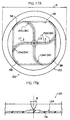
- Fig. 16A is a plan view illustrating a packing according to a variant example of the second embodiment of the present invention.
- Fig. 16B is a cross sectional view taken along the line XVI-XVI in Fig. 16A and illustrates the packing according to the variant example of the second embodiment of the present invention.
- Fig. 17A is a plan view illustrating yet another packing according to the present invention.
- Fig. 17B is a cross sectional view taken along the line XVII-XVII in Fig. 17A and illustrates yet another packing according to the present invention.
- Fig. 18A is an enlarged cross sectional view illustrating grooves of the packing according to the present invention.
- Fig. 18B is an enlarged cross sectional view illustrating grooves which are different from those shown in Fig. 18A.
- Fig. 18C is an enlarged cross sectional view illustrating grooves which are different from those shown in Figs. 18A and 18B.
- Fig. 19 is a plan view illustrating a conventional plugging sheet.
-
- A packing 10, a
cap 12 in which the packing 10 is mounted, and a photographic processing chemicals container 14 (a container for containing a photographic processing chemicals) to which thiscap 12 is attached, according to a first embodiment of the present invention are shown in Fig. 1. Further, the cross section of thecap 12 to which the packing 10 is mounted, and the packing 10 are shown in Figs. 2 and 3, respectively. The photographicprocessing chemicals container 14 which is shown in Fig. 1 contains therein photographic processing chemicals, and is an example of a container whose drainingport 18 is plugged by thecap 12, in which the packing 10 is mounted, being attached thereto. - The entire body of this photographic
processing chemicals container 14 is formed in a substantially rectangular cylindrical shape, and a cylindrically-shapedportion 16 is formed at one end of thecontainer 14 in the axial direction thereof (at the upper end in Fig. 1). One end of thecylindrical portion 16 is used as a drainingport 18, and it is possible to drain the photographic processing chemicals which are contained in the photographicprocessing chemicals container 14 from this drainingport 18. - As shown in Figs. 1 and 2, the
cap 12 in which the packing 10 is mounted, comprises an attachmentcylindrical portion 20 which is formed in a substantially cylindrical shape, and an anchoringcylindrical portion 22 which is formed integrally with one axial end of the attachment cylindrical portion 20 (at the upper end in Fig. 2) and whose diameter is smaller than the attachmentcylindrical portion 20. - As shown in Fig. 2, a
female thread 24 is formed on the internal circumferential surface of the attachmentcylindrical portion 20. Thefemale thread 24 is screwed onto a male thread 26 (see Fig. 1) which is formed on the external circumferential surface of thecylindrical portion 16 of the photographicprocessing chemicals container 14. Accordingly, thecap 12 is screwed onto thecylindrical portion 16 and can be attached to the drainingport 18. - An
annular ring 28 is formed integrally with the anchoringcylindrical portion 22 at one end in the axial direction thereof (the upper end in Fig. 2) so as to extend toward the inside of the anchoringcylindrical portion 22 in the radial direction. Apacking mounting portion 32 in which the packing 10 is mounted is formed by theinternal surface 22B of the anchoringcylindrical portion 22 and thebottom surface 28B of thering 28. - In the state in which the packing 10 is mounted in the
packing mounting portion 32, a clearance of a predetermined distance is formed between the external circumferential surface of an insertioncylindrical portion 36 and the internal circumferential surface of the attachmentcylindrical portion 20. When thecap 12 is screwed onto thecylindrical portion 16 of the photographicprocessing chemicals container 14, and is attached to the drainingport 18, the upper portion of thecylindrical portion 16 enters into the aforementioned clearance. As a result, the insertioncylindrical portion 36 is inserted into the draining port 18 (at the inside of the cylindrical portion 16) with no clearance. Accordingly, the external circumferential surface of the insertioncylindrical portion 36 and the internal circumferential surface of thecylindrical portion 16 contact with each other, and the position of the packing 10 in the radial direction of the photographicprocessing chemicals container 14 is fixed. Further, since the outer edge of asealing disc portion 34 is nipped between thebottom surface 28B of thering 28 and the upper surface of thecylindrical portion 16, the position of the packing 10 in the axial direction of the photographicprocessing chemicals container 14 is fixed. Moreover, in this state, when thecap 12 in which the packing 10 is mounted is attached to the drainingport 18, the drainingport 18 is plugged by the packing 10. - A protruding
wall 30 is formed so as to protrude from thetop surface 28A of thering 28 over the entire circumference of thering 28. - The cross section of the protruding
wall 30 is formed in a substantially triangular shape having a guidingsurface 30A and asloping surface 30C. As seen from the cross section, the guidingsurface 30A is parallel with axis J1. Thesloping surface 30C extends from a protrudingtip 30B towards the radial external side of thering 28 as it approaches thetop surface 28A of thering 28. By forming the protrudingwall 30 having the configuration described above so as to protrude from thetop surface 28A, then in a state where the drainingport 18 faces downward, and the photographicprocessing chemicals container 14 is held such that the axis J1 corresponds to the vertical direction of the photographic processing chemicals container 14 (see Figs. 8 and 9B), thesloping surface 30C rises toward the radial external side. Accordingly, when a liquid material is contained in the photographicprocessing chemicals container 14, then even if the drainingport 18 faces downward and the material contained in the photographicprocessing chemicals container 14 flows out due to gravity, the material rises thesloping surface 30C due to surface tension or the like as it empties out and, as a result, the material does not drain in the radial external direction of the photographicprocessing chemicals container 14. - The packing 10 is formed from unfoamed resin. The resin contains 50% or more of low density polyethylene (LDPE) whose density range is determined to be between 0.910 and 0.929 (g/cm3) in JIS K 6748-1982, or similarly, 50% or more of high density polyethylene (HDPE) whose density range is determined to be equal to or more than 0.942 (g/cm3) in JIS K 6748-10.982. As shown in Figs. 3, 4A and 4B in more detail, the packing 10 is formed by the
sealing disc portion 34 and the insertioncylindrical portion 36 which are formed integrally with each other. Thesealing disc portion 34 is formed in a substantially disc shape having a constant thickness L. The insertioncylindrical portion 36 is formed in a flattened cylindrical shape and extends perpendicularly to thesealing disc portion 34 from a portion adjacent to the external circumference of therear surface 34B of thesealing disc portion 34. The radial external side portion of the insertioncylindrical portion 36 functions as aflange 38. Theflange 38 has a constant thickness L, and imparts a predetermined strength to thesealing disc portion 34. Further, the outer diameter R of the sealing disc portion 34 (see Fig. 4A) ranges from not less than 0.5 cm to not more than 5 cm, and thesealing disc portion 34 has a predetermined strength. - As shown in Figs. 4A and 4B, by decreasing the thickness of the
sealing disc portion 34 in portions (to a thickness T2, see Fig. 6), a plurality of arcuate thin portions 46 (four in the present embodiment), each of which is formed in a substantially arcuate shape as seen from a plan view, are formed on thesurface 34A of thesealing disc portion 34 at a predetermined distance from each other in the circumferential direction.Circular arc portions 46A of the arcuatethin portions 46 correspond to the internal circumference of theflange 38. - As shown in Figs. 4A and 4B,
grooves 50 are formed on thesurface 34A of thesealing disc portion 34. Thegrooves 50 are formed by a plurality ofradial grooves 52,curved grooves 54, andcircumferential grooves 56. The plurality of radial grooves 52 (four in the present embodiment) extend linearly from the center of thesurface 34A of thesealing disc portion 34 toward the external circumference of the sealing disc portion 34 (toward the center of each of the arcuate thin portions 46). Each of thecurved grooves 54 continues on from the extendingend 52A of each of theradial grooves 52 and curves in a smooth circular arc without deviation in the same direction and at a constant angle of curvature with the same central angle. Each of thecircumferential grooves 56 extends without deviation from the tip end of each of thecurved grooves 54 along the external circumference of thesealing disc portion 34 so as to form a smooth circular arc shape. A portion between thegrooves 50 adjacent to each other is afan portion 58 which is formed in a substantially fan shape having a thickness L which is the same as theflange 38. - As shown in Figs. 4B, 7A, 7B, and 18A in more detail, each of the
grooves 50 is cut diagonally from thesurface 34A to therear surface 34B of thesealing disc portion 34 so as to form a substantially V-shaped cross section having a pair of sloping surfaces 60. The angle Θ formed by the slopingsurfaces 60 has a predetermined angle which is more than 0° and equal to or less than 120°. The distance between the slopingsurfaces 60 gradually decreases from thesurface 34A to therear surface 34B, of thesealing disc portion 34. By forming thisgroove 50, athin portion 62 having a predetermined thickness T3 is formed between abottom end 50A of thegroove 50 and therear surface 34B of thesealing disc portion 34. - The length L1 of each of the
radial grooves 52 has a predetermined length such that thetip end 52A of theradial groove 52 does not extend to the arcuate thin portion 46 (i.e., the length of theradial groove portion 52 is smaller than the radius of the sealing disc portion 34). More specifically if the internal circumference of the flange 38 (a circle which is formed by thecircular arc portions 46A of the arcuate thin portions 46) is R1, then preferably,
and more preferably,radial grooves 52, and thecurved grooves 54 are formed so as to extend directly from the center of thesealing disc portion 34. Accordingly, thesecurved grooves 54 equate to both the radial portions and the curved portions of the present invention. In the packing 10 according to the present embodiment, R1=13 mm, and L1=5mm. - As shown in Figs. 4A, 4B, and 5, a
low strength portion 64 is formed on each of theradial grooves 52 within a predetermined range from the center of the sealing disc portion 34 (within the range indicated by a double-dashed line C1 in Fig. 4A), by not changing the width W of the upper end of the radial groove 52 (see Figs. 7A and 7B), but by deeply cutting the radial groove 52 (accordingly, the inclination angle Θ formed by the slopingsurfaces 60 is made smaller) thus further decreasing the thickness of the thin portion 62 (thickness T2). - The thickness T2 of the
low strength portion 64 is set to range from not less than 0.05 mm to not more than 0.7 mm. Further, the thickness T2 is set such that the ratio of the plate thickness L of thesealing disc portion 34 to the thickness T2 of the low strength portion 64 (L/T2) is 2 or more. - As shown in Fig. 4A, the
curved grooves 54 are curved in a circular arc shape, continuing on from the tip ends 52A of theradial grooves 52 in the same direction (in the clockwise direction in Fig. 4A in the present embodiment), at a predetermined radius of curvature R2, and at a predetermined central angle. Each of thecurved grooves 54 contacts with achord portion 46B (a straight line portion) of each of the arcuatethin portions 46, and gradually extends toward the external circumference of thesealing disc portions 34. - The radius of curvature R2 of the
curved groove 54 is appropriately determined from a standpoint of perforation performance or the like which will be described later. However, preferably, - If the
curved groove 54 is thought of as being divided into micro portions, in these micro portions, it is not necessary to maintain the radius of curvature R2 constant. The respective micro portions may have different radii of curvature R2 or a portion thereof may be formed by a straight line connecting internal portions of the arc provided that the smoothness of thecurved groove 54 as a whole is not lost. - As shown in Figs. 5, 6 and 7B, the strength of the
thin portion 62 of each of thecurved grooves 54 is made to be much lower at a portion of thesealing disc portion 34 outside a predetermined range from the center of the sealing disc portion 34 (outside the range indicated by the double-dashed line C2 in Fig. 4A) without changing the width W of the upper end of thecurved groove 54, by deeply cutting thecurved groove 54 and thereby decreasing the thickness of the thin portion 62 (thickness T2). - Either one of the pair of sloping
surfaces 60 which are shown in Figs. 7A and 7B is not formed at a portion at which thecurved groove 54 is formed along thechord portion 46B of the arcuatethin portion 46. However, in this portion also, the thickness of the arcuatethin portion 46 is T2 so that, essentially, thecurved groove 54 is formed. - As shown in Fig. 6, the
circumferential grooves 56 extend from the respective tip ends of thecurved grooves 54 along the external circumference of thesealing disc portion 34. Thecircumferential grooves 56 are different from theradial grooves 52 and thecurved grooves 54 in that each of thecircumferential grooves 56 is formed by a single slopingsurface 60 extending from thesurface 34A to therear surface 34B of thesealing disc portion 34, and by avertical surface portion 46C which forms the circulararcuate portion 46A of the arcuatethin portion 46. Thethin portions 62 having the same thickness T2 as the arcuatethin portions 46 are formed by thecircumferential grooves 56. Accordingly, as can be seen from an overall view of thegrooves 50 in Figs. 4A, 4B, and 5, thelow strength portion 64 in which the thickness of thethin portion 62 is decreases even further (thickness T2) is formed within the range from the center of thesealing disc portion 34 to the double-dashed line C1. Within the range between the double-dashed line C1 and the double-dashed line C2, the thickness of thethin portion 62 is not decreased any more (thickness T3) so that a constant strength can be maintained. Outside the range indicated by the double-dashed line C2, the thickness of thethin portion 62 is decreased once more (thickness T2). - Next, a description of a direction in which photographic processing chemicals are drained from the photographic
processing chemicals container 14 whose drainingport 18 is plugged by the packing 10 according to the present embodiment, and an operation of the packing 10 will be given. - A photographic processing
chemicals supplying device 70 in the automatic developer is schematically shown in Fig. 8. When the photographicprocessing chemicals container 14 is set in the photographic processingchemicals supplying device 70, the photographic processing chemicals are supplied from thecontainer 14. - In order to supply the photographic processing chemicals from the photographic
processing chemicals container 14 into the automatic developer, as shown in Fig. 8, firstly, the photographicprocessing chemicals container 14 is inserted into a holding hole 74 of a holdingplate 72 and set upside down. The photographicprocessing chemicals container 14 is held above a replenishing tank (not shown) in a state where the draining port 18 (see Fig. 1) faces downward. At this time, because the drainingport 18 of the photographicprocessing chemicals container 14 is plugged by the packing 10, the photographic processing chemicals does not flow out inadvertently from the photographicprocessing chemicals container 14. Further, as shown in Fig. 9B, the upper end of a perforatingpipe 76 which is provided in the photographic processingchemicals supplying device 70 is positioned beneath the packing 10 plugging the drainingport 18. - Next, an unillustrated controller rotates a pinion inside a driving
portion 78 and raises an elevatingportion 80. The perforatingpipe 76 extending from the elevatingportion 80 is thereby raised, and the tip end of the perforatingpipe 76 pushes up the central portion of the packing 10 which plugs the drainingport 18. - As shown in Figs. 10A and 10B, when the center of the packing 10 is pressed up by the tip end of the perforating
pipe 76, in the vicinity of the center of thesealing disc portion 34, the tensional force acts upon thefan portions 58, which are provided on both side portions of each of the radial grooves 52 (see Fig. 4) which form thegrooves 50, in the direction in which thefan portions 58 are separated from each other. - Generally, when a member with a fixed thickness is pressed in the direction of that thickness and is broken, the maximum amount of pressing force (perforation force) is needed at the initial stage of the pressing, i.e., immediately before and after perforation starts. In the packing 10 according to the present embodiment, among the
thin portions 62,low strength portions 64 are formed at portions of thethin portions 62 within the range indicated by the double-dashed line C1 in Fig. 4, and the strength thereof is weakened. Accordingly, even if the force for elevating the perforatingpipe 76 is small, in other words, even if the rotational torque of the pinion of the drivingportion 78 is small, thesealing disc portion 34 can be broken along theradial grooves 52. Namely, thethin portions 62 in the vicinity of the central portion of thesealing disc portion 34 can be split with a small amount of pressing force. Accordingly, thesealing disc portion 34 can be broken along thethin portions 62. - As shown in Figs. 11A and 11B, when the perforating
pipe 76 is further raised, the splits extend to the external side of thesealing disc portion 34 in the radial direction thereof, and further extend to thethin portions 62 which are formed by the curved grooves 54 (see Fig. 4A). During this splitting process, the splits extend from thelow strength portion 64 to a portion of thethin portion 62 at which thelow strength portion 64 is not formed (within the range between the double-dashed line C1 and the double-dashed line C2 in Fig. 4A). However, at this time, since splits have already been formed on thesealing disc portion 34, these splits can be expanded with a small amount of pressing force. - As can be seen from Fig. 4A, since the
curved grooves 54 continue on from the radialcurved grooves 52 without deviation, and are curved at a constant radius of the curvature, the tensional force acts upon thefan portions 58 which are provided on both sides of each of thecurved grooves 54 in the direction where thefan portions 58 are forced to separate from each other. As a result, the splits extend smoothly toward the external side portion of thesealing disc portion 34 in the radial direction thereof along thecurved grooves 54. - Among the
thin portions 62 which are formed by thecurved grooves 54, the thickness of a portion of each of thethin portions 62 outside the range indicated by the double-dashed line C2 in Fig. 4A is decreased again (thickness T2), and the strength thereof is made low. For this reason, when the splits extend to these low strength portions, thesealing disc portion 34 is broken with a smaller amount of pressing force. Especially when the splits extend to thechord portions 46B of the arcuatethin portions 46, only thefan portion 58 on one side of each of thethin portions 62 is pulled away from the arcuatethin portion 46. However, even in this case, the splits expand along the low strength portions of thethin portions 62 which are formed by thecurved grooves 54, and extend to thethin portions 62 which are formed by thecircumferential grooves 56. - When splits further expand along the
thin portions 62, and thesealing disc portion 34 is broken, because the thin portions 62 (the circumferential grooves 56) are formed along the external circumference of thesealing disc portion 34, as shown in Figs. 12A and 12B, each of thefan portions 58 is thereby bent at thechord portion 46B of the arcuatethin portion 46. Namely, as is also shown in Fig. 13, thesealing disc portion 34 is opened and the area of the opening is made wider (in contrast to this, for example, when thecircumferential groove 56 is not formed on thesealing disc portion 34, since thefan portion 58 is bent along the line indicated by the double-dashed line C3 which is shown in Fig. 4A, the area of the opening of thesealing disc portion 34 is made narrower). - In this way, in the packing 10 according to the present embodiment,
curved grooves 54, which continue on smoothly without deviation from theradial grooves 52, andcircumferential grooves 56, which continue on smoothly without deviation from thecurved grooves 54 along the external circumference of thesealing disc portion 34, are formed on thesealing disc portion 34 for plugging the drainingport 18 of the photographicprocessing chemicals container 14. As a result, thesealing disc portion 34 can be opened wide with a small amount of pressing force. - In the packing 10 according to the present embodiment, since the
low strength portions 64 are formed at portions within a predetermined range from the center thereof (within the range indicated by the double-dashed line C1 which is shown in Fig. 4A) of thethin portions 62 which are formed on thesealing disc portion 34 as compared to the packing in which the strength of these portions is not reduced, the sealingdisc plate 34 is broken with a smaller amount of pressing force, and the drainingport 18 of the photographicprocessing chemicals container 14 can thereby be opened. - Further, because the strength at portions of the
thin portions 62 within the range between the double-dashed line C1 and the double-dashed line C2 is not reduced, thesealing disc portion 34 maintains a constant strength. Accordingly, due to, for example, a change or the like of the internal pressure of the photographicprocessing chemicals container 14, even if thesealing disc portion 34 is pressed outwardly or inwardly of the photographicprocessing chemicals container 14, thesealing disc portion 34 is not broken unexpectedly. Especially when the photographicprocessing chemicals container 14 is dropped, the internal pressure of thecontainer 14 may increase temporarily, however, even in this case, thesealing disc portion 34 is not broken. - In the packing 10 according to the present embodiment, since the outer diameter of the
sealing disc portion 34 is between not less than 0.5 cm and not more than 5 cm, thesealing disc portion 34 stretches appropriately due to pressing force from the pressing means (however, it does not stretch excessively), thesealing disc portion 34 can be broken with a small amount of pressing force. - As described above, in the packing 10 according to the present embodiment, opposing properties can be realized, namely, that a predetermined amount of strength is maintained in the
sealing disc portion 34, and the pressing force which is needed by the pressing means to perforate this sealing disc portion 34 (i.e., the perforating force of the perforating pipe 76) can be minimized. - A packing 110 according to the second embodiment of the present invention is shown in Fig. 14. In this packing 110, only the configuration of grooves in the second embodiment of the present invention is different as compared to the packing 10 according to the first embodiment of the present invention. Structural parts and members identical to those of the packing 10 according to the first embodiment are denoted by the same reference numerals, and a description thereof will be omitted.
- In this packing 110, as shown in Fig. 14A, among four
thin portions grooves 112, as a whole, the thickness of each of the twothin portions thin portions thin portions thin portions - Generally, the relationship which is shown in Fig. 15A exists between the length of a split which is formed by the
sealing disc portion 116 being pressed by the pressing means (the perforating pipe 76), and the pressing force which is generated by the pressing means and is needed to expand the split. The relationship between the distance moved (on the basis of the distance moved from the tip end of the perforatingpipe 76 at the point the tip end contacts with the sealing disc portion) and the pressing force of the perforatingpipe 76 is shown in the graph in Fig. 15A. As can be seen from this graph, if the four thin portions have the same thickness, at a stage in which the distance moved by the perforatingpipe 76 is small, the pressing force amounts to its maximum value F1 (which is referred to as maximum pressing force, hereinafter). At this point, splits are formed at the thin portions. Once splits are formed on thesealing disc portion 34, only a small amount of pressing force is needed in order to expand the splits. Accordingly, after the pressing force has exceeded the maximum pressing force F1, the pressing force decreases invariably. - Conversely, the relationship between the distance moved and the pressing force of the perforating
pipe 76 when asealing disc portion 116 of the packing 110 is pressed and broken by the perforatingpipe 76 is shown in Fig. 15B. In the packing 110, since the strength at thethin portions thin portions thin portions thin portions - Accordingly, when the center of the
sealing disc portion 116 of the packing 110 is pressed by the perforatingpipe 76, splits are formed at thethin portions sealing disc portion 116 is thereby broken. When the splits extend to the portions near the external circumference of thesealing disc portion 116, since the amount of pressing force which is needed to form splits at thethin portions thin portions sealing disc portion 116 is thus entirely broken, and the draining port 18 (see Fig. 1) is opened. - Among the four
thin portions thin portions thin portions fan portions 58 adjacent to each other by the pressing force of the pressing means can be dispersed at different times. Accordingly, thesealing disc portion 116 can be broken with a small amount of pressing force. Further, splits can be first induced at thethin portions thin portions thin portions thin portions sealing disc portion 116 can be kept constant and even when thesealing disc portion 116 is pressed inwardly or outwardly of the photographicprocessing chemicals container 14, thesealing disc portion 116 does not unexpectedly break. - In order to disperse the tensional force acting upon the
fan portions 58 adjacent to each other, it is not necessary to reduce the strength of two of the plurality of thin portions and instead, the strength of one thin portion or three or more of the thin portions may be made to be lower than the other thin portions. Further, when the number of thin portions is equal to or more than three (accordingly, the number of thefan portions 58 is equal to or more than three), the above-described effect which is obtained by forming low strength thin portions (the tensional force acting upon thefan portions 58 is dispersed at different times) can be accomplished. - As shown in Fig. 14B,
high strength portions 118 where the thickness of thethin portions high strength portions 118, splits which are formed at thethin portions thin portions thin portions high strength portions 118, the fourthin portions sealing disc portion 116 is thereby broken. - By forming the
high strength portions 118 at the fourthin portions thin portions thin portions sealing disc portion 116 can be broken. - Instead of the
high strength portions 118 which are shown in Fig. 14B, as shown in Figs. 16A and 16B, within the local areas P, each of which is spaced apart from the center of thesealing disc portion 116, the thickness of thethin portions thin portions high strength portions 120 can be formed. In this way, by forming thehigh strength portions 120 locally, as compared to the packing 110 having the cross section which is shown in Fig. 14B, after the tip ends of splits have exceeded thehigh strength portions 120, the splits can extend with a small amount of pressing force, and thesealing disc portion 116 can be broken. - A packing 130 as an another example is shown in Figs. 17A and 17B. In this packing 130, within a predetermined range from the center of a sealing disc portion 132 (within the range indicated by the double-dashed line C5), the thickness of each of
thin portions 136 which are formed bygrooves 134 is made larger in portions by increasing the angle Θ which is formed by the sloping surfaces 60 (see Figs. 7A and 7B), and the strength thereof thereby increases. For this reason; as compared, for example, to the packing 10 according to the first embodiment of the present invention, at the initial stage of perforating thesealing disc portion 132, it is necessary to press thesealing disc portion 132 with a larger amount of pressing force. However, once splits are formed at each of thethin portions 136, and the tip ends of the splits extend to the range of thesealing disc portion 132 outside the range indicated by the double-dashed line C5, the splits extend to the outside of thesealing disc portion 132 in the radial direction thereof with an extremely small amount of pressing force, and thesealing disc portion 132 can be opened. - In the above description, as is also shown in Fig. 18A, an example in which the sloping
surfaces 60 which form thegrooves grooves grooves surfaces 60 do not contact with each other and are separated from each other. Aflat portion 66 which is parallel with therear surface 34B of thesealing disc portion 34 is formed between the bottom ends 60A of the sloping surfaces 60. Further, a curved portion may be formed which is curved so as to form a concave shape protruding towards therear surface 34B, between the bottom ends 60A of the sloping surfaces 60. Moreover, as shown in Fig. 18C, the slopingsurfaces 60 may be formed perpendicular to thetop surface 34A and therear surface 34B, of the sealing disc portion 34 (therefore, in actual fact, the slopingsurfaces 60 do not slope) in a rectangular shape having aflat portion 66 between the bottom ends of the sloping surfaces 60. - As to the structure in which the
thin portions thin portions surfaces 60 has been explained. However, the structure in which each of thethin portions surfaces 60 are separated from each other by a predetermined distance and each of thethin portions flat portion 66 having a predetermined width, it is possible for each of thethin portions flat portion 66. Namely, if the width of theflat portion 66 of each of thethin portions surfaces 60 without aflat portion 66 therebetween, as is shown in Fig. 18A), the tensional force is concentrated within this narrow range. Accordingly, the elongation of thethin portions 62 as a whole in the tensional direction decreases, and thethin portions 62 split easily. However, if the width of theflat portion 66 is made wider, since the tensional force is dispersed within this wider range, the elongation of thethin portions 62 as a whole in the tensional direction increases, and thethin portions 62 do not split easily. - The
thin portions sealing disc portion 34 to the outer circumference thereof. Namely, even in this case, provided that thecurved grooves 54 which continue in a smooth without deviation from the extending ends 52A of theradial grooves 52 are formed and, provided that thecircumferential grooves 56 which continue in a smooth arcuate shape without deviation from thecurved grooves 54 along the outer circumference of thesealing disc portion 34 are formed, thesealing disc portion 34 can be opened wide with a small amount of pressing force. - The
thin portions sealing disc portion 34 to the thickness T2 of thelow strength portion 64 is set to be equal to or more than 2, (L/T4) is set to be equal to or more than 2, and thesealing disc portion 34 can thereby be opened wide with a small amount of pressing force. - The number of each of the
grooves sealing disc portion grooves sealing disc portions fan portions 58 and the pressing means decreases. On the other hand, if the number of thegrooves sealing disc portions grooves sealing disc portions - The
grooves - The low strength portions according to the present invention are not limited to the
grooves portions - As described above, the sealing disc portion can be broken along a weld line simply by forming the weld line, however, by further forming the
grooves - In the above description, an example in which each of the
packings cap 12 has been explained. However, therespective packings cap 12. In this way, when each of thepackings cap 12 and, each of thepackings cap 12. - In the above description, an example of the photographic
processing chemicals container 14 in which the photographic chemicals are contained has been explained. However, the present invention is not limited to this and instead, any type of container can be used. - As photographic processing chemicals contained in the photographic
processing chemicals container 14, for example, a color developing solution, a black & white developing solution, a bleaching solution, a fixing solution, or the like can be listed. These photographic processing chemicals are used to treat a halogen silver photosensitive material, are commercially available, and are known. - In the above description, as a material which forms the
packings processing chemicals container 14 in which the photographic processing chemicals are contained is used, from a standpoint of chemical resistance or physical strength, polyethylene is listed as one of the preferable materials. - Especially, in the case in which the packing is formed from a resin material which contains a large amount of low density polyethylene (LDPE), as compared to when the packing is formed from a resin material which contains high density polyethylene (HDPE), because the resin itself is soft, the packing is apt to elongate. Accordingly, the central portion of each of the
sealing disc portions pipe 76 is short, it is possible that the central portions of thesealing disc portions pipe 76, splits which have been formed on thesealing disc portions sealing disc portions sealing disc portions sealing disc portions processing chemicals container 14 is dropped, even if the internal pressure of thecontainer 14 changes, this change of the internal pressure can be absorbed by thesealing disc portions - On the other hand, if the
packings packings sealing disc portions sealing disc portions sealing disc portions sealing disc portions thin portions 62 which are structured by thegrooves 50. Accordingly, even if the distance moved by the perforatingpipe 76 is small, it is possible to open thesealing disc portions sealing disc portions fan portions 58 to return to the original position they were in before the sealing disc portions were opened so that each of thesealing disc portions fan portions 58 and the perforatingpipe 76 due to liquid pressure or the like, when the material contained in the container (photographic processing chemicals or the like) is drained does not decrease, and the draining of the contents can be ensured. - The above-described conditions may be realized by using a resin which contains a large amount of middle density polyethylene (MDPE) having a density range of between 0.930 and 0.941 (g/cm3) in JIS K 6748-1982.
- As described above, a method of opening the packing 10, 110, and 130 is not limited to the case in which the photographic
processing chemicals container 14 is set in the photographic processing chemicals supplying device 70 (see Fig. 8) in an automatic developer, and the packing 10 is pressed by the perforatingpipe 76. For example, thepackings
Claims (9)
- A plugging member which plugs a draining port for draining a material which is contained in a container, comprising:a plugging plate body which is mounted in said draining port and is able to plug said draining port; anda thin portion which is formed by decreasing the thickness of said plugging plate body in portions in the thickness direction thereof, using a concave portion which is formed linearly on one end surface of said plugging plate body in the thickness direction thereof and which is formed with a predetermined width or with a width which decreases from said one end surface to the other end surface of said plugging plate body in the thickness direction thereof,
wherein the thinnest portion of said thin portion has the thickness T2 which ranges from not less than 0.05 mm to not more than 0.7 mm,the surfaces which face each other and form said concave portion are in parallel with each other, or the angle Θ which is formed by said facing surfaces is more than 0° and equal to or less than 120°, andthe ratio (L/T2) of the thickness L of said plugging plate body to said thickness T2 is equal to or more than 2. - A plugging member according to claim 1, wherein a low strength portion is formed at said thin portion by decreasing the strength of said thin portion within a predetermined range from the center of said plugging plate body.
- A plugging member according to claim 1, wherein three or more of said thin portions are formed, and a portion of these thin portions are low strength portions whose strength is made lower than the other thin portions.
- A plugging member according to claim 3, wherein a high strength portion is formed at said thin portions by increasing the strength of the thin portions outside of a predetermined range from the center of said plugging plate body.
- A plugging member according to claims 1 to 4, wherein said plugging plate body is formed in a disc plate shape whose outer diameter R is not less than 0.5 cm and not more than 5 cm.
- A plugging member which plugs a draining port for draining a material which is contained in a container, comprising:a plugging plate body which is mounted in said draining port and is able to plug the draining port; anda low strength portion which is formed on said plugging plate body where the strength of said plugging plate body is decreased by a plurality of radial portions which are formed radiating out from substantially the central portion of said plugging plate body toward the external edge thereof, a plurality of curved portions which are formed so as to be curved in an arcuate shape and continue from the tip end of each of said radial portions, and a plurality of circumferential portions which are formed so as to extend from the tip end of each of said curved portions in the direction along the edge of the opening of said draining port.
- A plugging member according to claim 6, wherein said low strength portion is a groove which is formed by decreasing the thickness of said plugging plate body in portions.
- A plugging member according to claim 1 to 7, wherein a container in which a draining port for draining a material contained therein is formed, and said draining port is plugged by said plugging member.
- A container according to claim 8, wherein said material is photographic processing chemicals.
Priority Applications (1)
| Application Number | Priority Date | Filing Date | Title |
|---|---|---|---|
| EP04009104A EP1481910B1 (en) | 1998-03-31 | 1999-03-26 | Plugging member and container |
Applications Claiming Priority (4)
| Application Number | Priority Date | Filing Date | Title |
|---|---|---|---|
| JP10578798 | 1998-03-31 | ||
| JP10578898 | 1998-03-31 | ||
| JP10105788A JPH11292124A (en) | 1998-03-31 | 1998-03-31 | Closure member and container |
| JP10105787A JPH11292123A (en) | 1998-03-31 | 1998-03-31 | Closure member and container |
Related Child Applications (1)
| Application Number | Title | Priority Date | Filing Date |
|---|---|---|---|
| EP04009104A Division EP1481910B1 (en) | 1998-03-31 | 1999-03-26 | Plugging member and container |
Publications (3)
| Publication Number | Publication Date |
|---|---|
| EP0947441A2 true EP0947441A2 (en) | 1999-10-06 |
| EP0947441A3 EP0947441A3 (en) | 2000-05-03 |
| EP0947441B1 EP0947441B1 (en) | 2007-03-07 |
Family
ID=26446021
Family Applications (2)
| Application Number | Title | Priority Date | Filing Date |
|---|---|---|---|
| EP04009104A Expired - Lifetime EP1481910B1 (en) | 1998-03-31 | 1999-03-26 | Plugging member and container |
| EP99105145A Expired - Lifetime EP0947441B1 (en) | 1998-03-31 | 1999-03-26 | Plugging member and container |
Family Applications Before (1)
| Application Number | Title | Priority Date | Filing Date |
|---|---|---|---|
| EP04009104A Expired - Lifetime EP1481910B1 (en) | 1998-03-31 | 1999-03-26 | Plugging member and container |
Country Status (5)
| Country | Link |
|---|---|
| US (2) | US20030042257A1 (en) |
| EP (2) | EP1481910B1 (en) |
| CN (1) | CN100421029C (en) |
| AT (2) | ATE357380T1 (en) |
| DE (3) | DE69935363T2 (en) |
Cited By (4)
| Publication number | Priority date | Publication date | Assignee | Title |
|---|---|---|---|---|
| US6902076B2 (en) | 2002-02-21 | 2005-06-07 | Eastman Kodak Company | Bottle and bottle closure assembly |
| WO2009031601A1 (en) | 2007-09-06 | 2009-03-12 | Lube Co., Ltd. | Cartridge tank for lubrication agent |
| DE102007055436A1 (en) * | 2007-11-21 | 2009-05-28 | Bayerische Motoren Werke Aktiengesellschaft | Pot sealing for bore in assembly flange for connecting fluid supplying components, particularly for bore in thermostat housing of internal combustion engine, has flange for support on assembly flange radially around bore |
| EP2655073A4 (en) * | 2010-12-20 | 2018-06-13 | FUJIFILM Corporation | Printing liquid container, printing liquid filled container, image forming apparatus and printing liquid filled container manufacturing method |
Families Citing this family (17)
| Publication number | Priority date | Publication date | Assignee | Title |
|---|---|---|---|---|
| CN100510955C (en) * | 2003-06-27 | 2009-07-08 | 富士胶片株式会社 | Photographic processing agent cartridge and container usable therein |
| US7234592B2 (en) * | 2003-06-27 | 2007-06-26 | Fujifilm Corporation | Photographic processing agent cartridge and container usable therein |
| CA2508161C (en) | 2005-05-24 | 2010-03-30 | Lawrence Wayne Vereschagin | Automatic banding device and method |
| JP4673134B2 (en) * | 2005-06-02 | 2011-04-20 | 株式会社ブリヂストン | Sealant storage and injection container |
| US7591388B2 (en) * | 2005-07-12 | 2009-09-22 | Philip Salvatore Amormino | Spill-resistant container |
| WO2008039248A1 (en) * | 2006-09-26 | 2008-04-03 | Cadbury Adams Usa Llc | Rupturable blister package |
| US9216850B2 (en) | 2006-09-26 | 2015-12-22 | Intercontinental Great Brands Llc | Rupturable substrate |
| PL2650229T3 (en) | 2008-12-22 | 2017-05-31 | Intercontinental Great Brands Llc | Severable film package enclosing stacked confectionery product pieces |
| EP2675420B1 (en) * | 2011-02-14 | 2016-04-20 | Becton, Dickinson and Company | Pierceable cap having single frangible seal |
| RU2660059C2 (en) * | 2013-12-21 | 2018-07-04 | ФАЗЕКАШ, Габор | Valvular closure element, closure cap comprising valvular closure element and method and apparatus for manufacturing valvular closure element |
| US20170297786A1 (en) * | 2016-04-14 | 2017-10-19 | Steven Michael Gillette | Puncturable safety seal |
| USD838588S1 (en) * | 2016-08-12 | 2019-01-22 | Edgewell Personal Care Brands, Llc. | Container diaphragm |
| CN111566021B (en) * | 2017-10-23 | 2022-04-12 | 万通集团公司 | Valve with a valve body |
| GB201820292D0 (en) * | 2018-12-13 | 2019-01-30 | Obrist Closures Switzerland | Flow control insert |
| US11547253B2 (en) * | 2020-01-21 | 2023-01-10 | The Clorox Company | Dispensing container |
| CN113830426B (en) * | 2020-06-23 | 2023-06-20 | 上海久连环保材料有限公司 | Wet towel cover with convenient paper extraction opening |
| CN113363785B (en) * | 2021-05-22 | 2023-09-05 | 中州恒宇建设有限公司 | Cable butt joint process |
Citations (1)
| Publication number | Priority date | Publication date | Assignee | Title |
|---|---|---|---|---|
| JPH0853147A (en) | 1994-04-28 | 1996-02-27 | Eastman Kodak Co | Method to discharge content from bottle,and plug element to implement said method |
Family Cites Families (39)
| Publication number | Priority date | Publication date | Assignee | Title |
|---|---|---|---|---|
| US571708A (en) | 1896-11-17 | Dust-guard for air-brake hose-couplings | ||
| US1989145A (en) * | 1933-10-06 | 1935-01-29 | Neal D Newby | Cap for collapsible tubes |
| FR1049694A (en) | 1952-01-21 | 1953-12-31 | Guarantee and ornamental cap for bottles and other cork-stoppered containers | |
| GB1090862A (en) | 1964-03-02 | 1967-11-15 | English Electric Co Ltd | Electrical protective relays |
| US3257026A (en) | 1964-07-17 | 1966-06-21 | Taylor Glenn | High pressure quick opening valve |
| US3380610A (en) | 1966-10-13 | 1968-04-30 | Container Corp | Snap-on lid for plastic container |
| DE2216615A1 (en) | 1972-04-06 | 1973-10-18 | Siemens Ag | SAFETY FITTINGS |
| CA1020892A (en) | 1972-09-08 | 1977-11-15 | Robert G. Clawson | Container wall with rupturable weakening line |
| US4105133A (en) | 1974-10-23 | 1978-08-08 | Aluminum Company Of America | Container wall with rupturable weakening line |
| US3921556A (en) | 1975-01-02 | 1975-11-25 | Black Sivalls & Bryson Inc | Scored reverse buckling rupture disk manufacturing method |
| US4053084A (en) * | 1976-03-01 | 1977-10-11 | Illinois Tool Works Inc. | Filler plug |
| DE2715992A1 (en) | 1977-04-09 | 1978-10-12 | Werner Puhlmann | RECEIVED GLASS COLLECTORS |
| DE2949469C2 (en) | 1979-12-05 | 1982-02-11 | Gebrüder Sulzer AG, 8401 Winterthur | Security element |
| US4426019A (en) * | 1981-10-15 | 1984-01-17 | The Coca-Cola Company | Membrane seal and knife combination for a post-mix beverage dispensing system |
| US4416388A (en) | 1982-09-20 | 1983-11-22 | Sexton Can Company, Inc. | Pressure relief device |
| US4463865A (en) | 1983-09-23 | 1984-08-07 | Bs&B Safety Systems, Inc. | Knife blade apparatus for severing rupture disks |
| US4655070A (en) | 1984-09-26 | 1987-04-07 | Clift Miner E | Scored concave-convex rupture disk and method of manufacture |
| US4902043A (en) | 1985-09-17 | 1990-02-20 | John T. Hoskins | Fluid coupling and seal assembly |
| GB8720683D0 (en) * | 1987-09-03 | 1987-10-07 | Metal Closures Ltd | Closures for containers |
| NL8801133A (en) | 1988-04-29 | 1989-11-16 | Elisabeth Josephine Borgerding | COVER FOR WASTE BARREL. |
| US4874102A (en) | 1988-05-09 | 1989-10-17 | Multi-Technology Inc. | Medical fail safe releasible locks and/or seals for capped disposable centrifuge containers, cryogenic vials and the like |
| JPH0694266B2 (en) | 1989-02-20 | 1994-11-24 | タカタ株式会社 | Airbag storage cover |
| US4884717A (en) * | 1989-03-20 | 1989-12-05 | Bussard Janice W | Non-spilling snack container |
| CA1307715C (en) | 1989-09-28 | 1992-09-22 | Gavin Mcgregor | Rupture disc pressure relief device |
| US5111946A (en) | 1990-11-30 | 1992-05-12 | Elliot Glanz | Safety bottle |
| GB2254836B (en) * | 1991-04-15 | 1995-01-04 | Suk Kyu Han | Container with a sealed tubular passage |
| US5455662A (en) | 1992-12-30 | 1995-10-03 | Ricoh Company, Ltd. | Developer replenishing device and developer container for use therewith |
| DE4318311C2 (en) * | 1993-06-02 | 2002-07-18 | Berlinger & Co Ag Ganterschwil | Safety screw cap for a container |
| JP3588142B2 (en) | 1993-06-30 | 2004-11-10 | 三洋電機株式会社 | Pressure vessel safety device |
| US5397023A (en) * | 1993-12-06 | 1995-03-14 | James River Corporation Of Virginia | Disposable cup lid having a tear-resistant straw through-slit |
| GB9402763D0 (en) * | 1994-02-14 | 1994-04-06 | Kodak Ltd | Photographic processing chemicals |
| FR2729920B1 (en) | 1995-02-01 | 1997-06-06 | Kerplas Snc | BOTTLE BODY AND BOTTLE FOR DISPENSING A PRODUCT |
| GB9503068D0 (en) | 1995-02-16 | 1995-04-05 | Kodak Ltd | Photographic processing chemicals |
| JPH08268451A (en) * | 1995-03-28 | 1996-10-15 | Piolax Inc | Seal plug |
| US5597019A (en) | 1995-03-30 | 1997-01-28 | Ecolab Inc. | Dilution system for filling spray bottles |
| DE69627510T2 (en) | 1995-09-01 | 2004-01-29 | Climes Conseil Claude Liardet | VALVE |
| US6000579A (en) * | 1997-01-21 | 1999-12-14 | Asahipen Corporation | Cap for a spray can, a spray can with the cap and a method for discharging residual liquid and gas in a spray can |
| US5871890A (en) | 1997-11-14 | 1999-02-16 | Eastman Kodak Company | Method for processing roomlight handleable radiographic films using two-stage development |
| US5984538A (en) | 1997-11-14 | 1999-11-16 | Eastman Kodak Company | Hand-held film developing device and kit for roomlight processing of black-and-white photographic elements |
-
1999
- 1999-03-23 US US09/274,319 patent/US20030042257A1/en not_active Abandoned
- 1999-03-26 AT AT04009104T patent/ATE357380T1/en not_active IP Right Cessation
- 1999-03-26 EP EP04009104A patent/EP1481910B1/en not_active Expired - Lifetime
- 1999-03-26 DE DE69935363T patent/DE69935363T2/en not_active Expired - Lifetime
- 1999-03-26 EP EP99105145A patent/EP0947441B1/en not_active Expired - Lifetime
- 1999-03-26 AT AT99105145T patent/ATE356044T1/en not_active IP Right Cessation
- 1999-03-26 DE DE69935621T patent/DE69935621T2/en not_active Expired - Lifetime
- 1999-03-26 DE DE04009104T patent/DE04009104T1/en active Pending
- 1999-03-31 CN CNB991047419A patent/CN100421029C/en not_active Expired - Lifetime
-
2003
- 2003-05-23 US US10/443,769 patent/US7011226B2/en not_active Expired - Lifetime
Patent Citations (1)
| Publication number | Priority date | Publication date | Assignee | Title |
|---|---|---|---|---|
| JPH0853147A (en) | 1994-04-28 | 1996-02-27 | Eastman Kodak Co | Method to discharge content from bottle,and plug element to implement said method |
Cited By (6)
| Publication number | Priority date | Publication date | Assignee | Title |
|---|---|---|---|---|
| US6902076B2 (en) | 2002-02-21 | 2005-06-07 | Eastman Kodak Company | Bottle and bottle closure assembly |
| WO2009031601A1 (en) | 2007-09-06 | 2009-03-12 | Lube Co., Ltd. | Cartridge tank for lubrication agent |
| EP2186745A1 (en) * | 2007-09-06 | 2010-05-19 | Lube Co., Ltd. | Cartridge tank for lubrication agent |
| EP2186745A4 (en) * | 2007-09-06 | 2010-09-01 | Lube Co Ltd | Cartridge tank for lubrication agent |
| DE102007055436A1 (en) * | 2007-11-21 | 2009-05-28 | Bayerische Motoren Werke Aktiengesellschaft | Pot sealing for bore in assembly flange for connecting fluid supplying components, particularly for bore in thermostat housing of internal combustion engine, has flange for support on assembly flange radially around bore |
| EP2655073A4 (en) * | 2010-12-20 | 2018-06-13 | FUJIFILM Corporation | Printing liquid container, printing liquid filled container, image forming apparatus and printing liquid filled container manufacturing method |
Also Published As
| Publication number | Publication date |
|---|---|
| US20030196984A1 (en) | 2003-10-23 |
| EP0947441B1 (en) | 2007-03-07 |
| CN100421029C (en) | 2008-09-24 |
| ATE357380T1 (en) | 2007-04-15 |
| ATE356044T1 (en) | 2007-03-15 |
| US7011226B2 (en) | 2006-03-14 |
| US20030042257A1 (en) | 2003-03-06 |
| EP1481910B1 (en) | 2007-03-21 |
| DE69935621D1 (en) | 2007-05-03 |
| CN1233781A (en) | 1999-11-03 |
| EP0947441A3 (en) | 2000-05-03 |
| DE69935363T2 (en) | 2007-12-20 |
| DE04009104T1 (en) | 2005-07-14 |
| DE69935363D1 (en) | 2007-04-19 |
| DE69935621T2 (en) | 2007-12-06 |
| EP1481910A1 (en) | 2004-12-01 |
Similar Documents
| Publication | Publication Date | Title |
|---|---|---|
| EP1481910B1 (en) | Plugging member and container | |
| US6209737B1 (en) | Cup assembly for bottle with attachment mechanism | |
| US6375067B1 (en) | Packaging container | |
| US6227410B1 (en) | Package, method for the manufacture thereof and coupling therefor | |
| CS274267B2 (en) | Dosing package | |
| AU632214B2 (en) | Carrier stock with tear-open tabs | |
| ATE483441T1 (en) | INSTILLATION TANK WITH HEIGHT DIFFERENCE PART | |
| US6158622A (en) | Closure to be attached to a container | |
| JPS60110650A (en) | Vessel with partial pouring stopper | |
| JPH0977137A (en) | Laminated plastic bottle | |
| US6021927A (en) | Degassing device for aerosol container and lid provided with degassing construction | |
| US6408904B1 (en) | Hygienic bottle cap | |
| TWI780286B (en) | Laminated peel container | |
| JPH11292123A (en) | Closure member and container | |
| JP2930581B1 (en) | Opening cap | |
| EP1470056B1 (en) | Drinking container with sealing device for a drinking straw and method for making it | |
| JP2005118536A (en) | Dripping nozzle of ophthalmic preparation container | |
| JPH092494A (en) | Flow rate adjusting housing member | |
| KR200379463Y1 (en) | Pouch for liquid filling | |
| JPH11292124A (en) | Closure member and container | |
| JP2000051117A (en) | Wet tissue case | |
| JPH0817820B2 (en) | Blood circuit branch device | |
| JP4698322B2 (en) | Pouring tool | |
| EP1565385B1 (en) | Connecting device | |
| KR102616620B1 (en) | Pouch |
Legal Events
| Date | Code | Title | Description |
|---|---|---|---|
| PUAI | Public reference made under article 153(3) epc to a published international application that has entered the european phase |
Free format text: ORIGINAL CODE: 0009012 |
|
| AK | Designated contracting states |
Kind code of ref document: A2 Designated state(s): AT BE CH CY DE DK ES FI FR GB GR IE IT LI LU MC NL PT SE |
|
| AX | Request for extension of the european patent |
Free format text: AL;LT;LV;MK;RO;SI |
|
| PUAL | Search report despatched |
Free format text: ORIGINAL CODE: 0009013 |
|
| 17P | Request for examination filed |
Effective date: 20000202 |
|
| AK | Designated contracting states |
Kind code of ref document: A3 Designated state(s): AT BE CH CY DE DK ES FI FR GB GR IE IT LI LU MC NL PT SE |
|
| AX | Request for extension of the european patent |
Free format text: AL;LT;LV;MK;RO;SI |
|
| AKX | Designation fees paid |
Free format text: DE |
|
| RBV | Designated contracting states (corrected) |
Designated state(s): AT BE CH CY DE DK ES FI FR GB GR IE IT LI LU MC NL PT SE |
|
| 17Q | First examination report despatched |
Effective date: 20030801 |
|
| GRAP | Despatch of communication of intention to grant a patent |
Free format text: ORIGINAL CODE: EPIDOSNIGR1 |
|
| GRAS | Grant fee paid |
Free format text: ORIGINAL CODE: EPIDOSNIGR3 |
|
| GRAA | (expected) grant |
Free format text: ORIGINAL CODE: 0009210 |
|
| STAA | Information on the status of an ep patent application or granted ep patent |
Free format text: STATUS: THE PATENT HAS BEEN GRANTED |
|
| AK | Designated contracting states |
Kind code of ref document: B1 Designated state(s): AT BE CH CY DE DK ES FI FR GB GR IE IT LI LU MC NL PT SE |
|
| PG25 | Lapsed in a contracting state [announced via postgrant information from national office to epo] |
Ref country code: NL Free format text: LAPSE BECAUSE OF FAILURE TO SUBMIT A TRANSLATION OF THE DESCRIPTION OR TO PAY THE FEE WITHIN THE PRESCRIBED TIME-LIMIT Effective date: 20070307 Ref country code: LI Free format text: LAPSE BECAUSE OF FAILURE TO SUBMIT A TRANSLATION OF THE DESCRIPTION OR TO PAY THE FEE WITHIN THE PRESCRIBED TIME-LIMIT Effective date: 20070307 Ref country code: FI Free format text: LAPSE BECAUSE OF FAILURE TO SUBMIT A TRANSLATION OF THE DESCRIPTION OR TO PAY THE FEE WITHIN THE PRESCRIBED TIME-LIMIT Effective date: 20070307 Ref country code: CH Free format text: LAPSE BECAUSE OF FAILURE TO SUBMIT A TRANSLATION OF THE DESCRIPTION OR TO PAY THE FEE WITHIN THE PRESCRIBED TIME-LIMIT Effective date: 20070307 Ref country code: BE Free format text: LAPSE BECAUSE OF FAILURE TO SUBMIT A TRANSLATION OF THE DESCRIPTION OR TO PAY THE FEE WITHIN THE PRESCRIBED TIME-LIMIT Effective date: 20070307 Ref country code: AT Free format text: LAPSE BECAUSE OF FAILURE TO SUBMIT A TRANSLATION OF THE DESCRIPTION OR TO PAY THE FEE WITHIN THE PRESCRIBED TIME-LIMIT Effective date: 20070307 |
|
| REG | Reference to a national code |
Ref country code: GB Ref legal event code: FG4D |
|
| REG | Reference to a national code |
Ref country code: CH Ref legal event code: EP |
|
| REF | Corresponds to: |
Ref document number: 69935363 Country of ref document: DE Date of ref document: 20070419 Kind code of ref document: P |
|
| RAP2 | Party data changed (patent owner data changed or rights of a patent transferred) |
Owner name: FUJIFILM CORPORATION |
|
| REG | Reference to a national code |
Ref country code: IE Ref legal event code: FG4D |
|
| PG25 | Lapsed in a contracting state [announced via postgrant information from national office to epo] |
Ref country code: SE Free format text: LAPSE BECAUSE OF FAILURE TO SUBMIT A TRANSLATION OF THE DESCRIPTION OR TO PAY THE FEE WITHIN THE PRESCRIBED TIME-LIMIT Effective date: 20070607 |
|
| PG25 | Lapsed in a contracting state [announced via postgrant information from national office to epo] |
Ref country code: ES Free format text: LAPSE BECAUSE OF FAILURE TO SUBMIT A TRANSLATION OF THE DESCRIPTION OR TO PAY THE FEE WITHIN THE PRESCRIBED TIME-LIMIT Effective date: 20070618 |
|
| NLT2 | Nl: modifications (of names), taken from the european patent patent bulletin |
Owner name: FUJIFILM CORPORATION Effective date: 20070502 |
|
| PG25 | Lapsed in a contracting state [announced via postgrant information from national office to epo] |
Ref country code: PT Free format text: LAPSE BECAUSE OF FAILURE TO SUBMIT A TRANSLATION OF THE DESCRIPTION OR TO PAY THE FEE WITHIN THE PRESCRIBED TIME-LIMIT Effective date: 20070807 |
|
| NLV1 | Nl: lapsed or annulled due to failure to fulfill the requirements of art. 29p and 29m of the patents act | ||
| REG | Reference to a national code |
Ref country code: CH Ref legal event code: PL |
|
| EN | Fr: translation not filed | ||
| PLBE | No opposition filed within time limit |
Free format text: ORIGINAL CODE: 0009261 |
|
| PG25 | Lapsed in a contracting state [announced via postgrant information from national office to epo] |
Ref country code: MC Free format text: LAPSE BECAUSE OF NON-PAYMENT OF DUE FEES Effective date: 20070331 Ref country code: IE Free format text: LAPSE BECAUSE OF NON-PAYMENT OF DUE FEES Effective date: 20070326 |
|
| 26N | No opposition filed |
Effective date: 20071210 |
|
| GBPC | Gb: european patent ceased through non-payment of renewal fee |
Effective date: 20070607 |
|
| PG25 | Lapsed in a contracting state [announced via postgrant information from national office to epo] |
Ref country code: IT Free format text: LAPSE BECAUSE OF FAILURE TO SUBMIT A TRANSLATION OF THE DESCRIPTION OR TO PAY THE FEE WITHIN THE PRESCRIBED TIME-LIMIT Effective date: 20070307 Ref country code: GR Free format text: LAPSE BECAUSE OF FAILURE TO SUBMIT A TRANSLATION OF THE DESCRIPTION OR TO PAY THE FEE WITHIN THE PRESCRIBED TIME-LIMIT Effective date: 20070608 Ref country code: FR Free format text: LAPSE BECAUSE OF FAILURE TO SUBMIT A TRANSLATION OF THE DESCRIPTION OR TO PAY THE FEE WITHIN THE PRESCRIBED TIME-LIMIT Effective date: 20071026 |
|
| PG25 | Lapsed in a contracting state [announced via postgrant information from national office to epo] |
Ref country code: GB Free format text: LAPSE BECAUSE OF NON-PAYMENT OF DUE FEES Effective date: 20070607 |
|
| PG25 | Lapsed in a contracting state [announced via postgrant information from national office to epo] |
Ref country code: FR Free format text: LAPSE BECAUSE OF FAILURE TO SUBMIT A TRANSLATION OF THE DESCRIPTION OR TO PAY THE FEE WITHIN THE PRESCRIBED TIME-LIMIT Effective date: 20070307 |
|
| PG25 | Lapsed in a contracting state [announced via postgrant information from national office to epo] |
Ref country code: CY Free format text: LAPSE BECAUSE OF FAILURE TO SUBMIT A TRANSLATION OF THE DESCRIPTION OR TO PAY THE FEE WITHIN THE PRESCRIBED TIME-LIMIT Effective date: 20070307 |
|
| PG25 | Lapsed in a contracting state [announced via postgrant information from national office to epo] |
Ref country code: LU Free format text: LAPSE BECAUSE OF NON-PAYMENT OF DUE FEES Effective date: 20070326 Ref country code: DK Free format text: LAPSE BECAUSE OF FAILURE TO SUBMIT A TRANSLATION OF THE DESCRIPTION OR TO PAY THE FEE WITHIN THE PRESCRIBED TIME-LIMIT Effective date: 20070607 |
|
| PGFP | Annual fee paid to national office [announced via postgrant information from national office to epo] |
Ref country code: DE Payment date: 20180313 Year of fee payment: 20 |
|
| REG | Reference to a national code |
Ref country code: DE Ref legal event code: R071 Ref document number: 69935363 Country of ref document: DE |