EP0948372B1 - Single operator exchange biliary catheter - Google Patents
Single operator exchange biliary catheter Download PDFInfo
- Publication number
- EP0948372B1 EP0948372B1 EP97940999A EP97940999A EP0948372B1 EP 0948372 B1 EP0948372 B1 EP 0948372B1 EP 97940999 A EP97940999 A EP 97940999A EP 97940999 A EP97940999 A EP 97940999A EP 0948372 B1 EP0948372 B1 EP 0948372B1
- Authority
- EP
- European Patent Office
- Prior art keywords
- guide wire
- catheter
- channel
- shaft
- sheath
- Prior art date
- Legal status (The legal status is an assumption and is not a legal conclusion. Google has not performed a legal analysis and makes no representation as to the accuracy of the status listed.)
- Expired - Lifetime
Links
Images


Classifications
-
- A—HUMAN NECESSITIES
- A61—MEDICAL OR VETERINARY SCIENCE; HYGIENE
- A61M—DEVICES FOR INTRODUCING MEDIA INTO, OR ONTO, THE BODY; DEVICES FOR TRANSDUCING BODY MEDIA OR FOR TAKING MEDIA FROM THE BODY; DEVICES FOR PRODUCING OR ENDING SLEEP OR STUPOR
- A61M25/00—Catheters; Hollow probes
- A61M25/01—Introducing, guiding, advancing, emplacing or holding catheters
- A61M25/0169—Exchanging a catheter while keeping the guidewire in place
-
- A—HUMAN NECESSITIES
- A61—MEDICAL OR VETERINARY SCIENCE; HYGIENE
- A61M—DEVICES FOR INTRODUCING MEDIA INTO, OR ONTO, THE BODY; DEVICES FOR TRANSDUCING BODY MEDIA OR FOR TAKING MEDIA FROM THE BODY; DEVICES FOR PRODUCING OR ENDING SLEEP OR STUPOR
- A61M25/00—Catheters; Hollow probes
- A61M25/0097—Catheters; Hollow probes characterised by the hub
-
- A—HUMAN NECESSITIES
- A61—MEDICAL OR VETERINARY SCIENCE; HYGIENE
- A61M—DEVICES FOR INTRODUCING MEDIA INTO, OR ONTO, THE BODY; DEVICES FOR TRANSDUCING BODY MEDIA OR FOR TAKING MEDIA FROM THE BODY; DEVICES FOR PRODUCING OR ENDING SLEEP OR STUPOR
- A61M25/00—Catheters; Hollow probes
- A61M25/01—Introducing, guiding, advancing, emplacing or holding catheters
- A61M2025/0183—Rapid exchange or monorail catheters
-
- A—HUMAN NECESSITIES
- A61—MEDICAL OR VETERINARY SCIENCE; HYGIENE
- A61M—DEVICES FOR INTRODUCING MEDIA INTO, OR ONTO, THE BODY; DEVICES FOR TRANSDUCING BODY MEDIA OR FOR TAKING MEDIA FROM THE BODY; DEVICES FOR PRODUCING OR ENDING SLEEP OR STUPOR
- A61M25/00—Catheters; Hollow probes
- A61M25/01—Introducing, guiding, advancing, emplacing or holding catheters
- A61M25/09—Guide wires
- A61M2025/09125—Device for locking a guide wire in a fixed position with respect to the catheter or the human body
Definitions
- the present invention relates to a catheter for use in catheter procedures accessed through the alimentary canal within the human anatomy and methods of using such a catheter.
- the catheter is used in conjunction with an endoscope for accessing the biliary tree.
- the present invention includes a catheter having a single operator exchange or rapid exchange feature which permits the use of a shorter guide wire, allows less time consuming procedures, and allows for larger diameter ancillary lumens within the catheter.
- Endoscopic procedures for treating abnormal pathologies within the alimentary canal system and biliary tree are increasing in number.
- the endoscope provides access to the general area of a desired duct using direct visualization.
- the duct itself must be navigated using a catheter in conjunction with fluoroscopy and guide wires.
- Catheters are known for treatment of targeted anatomical regions.
- Known methods and devices for using biliary catheters for accessing the biliary tree for performing catheter procedures are disclosed in US-A-5,397,302 US-A-5,320,602.
- an endoscope for treatment of an abnormal pathology within a patient's biliary tree, is first introduced into the mouth of the patient.
- the endoscope includes a proximal end and a distal end, and has a lumen extending longitudinally between the proximal and distal ends.
- the endoscope is guided through the patient's alimentary tract or canal until an opening at the distal end of the endoscope is proximate the area to receive treatment.
- the endoscope allows other components, such as a catheter, to access the targeted area.
- the distal end of the endoscope is positioned proximate the papilla of vater leading to the common bile duct and the pancreatic duct.
- a catheter is guided through the lumen of the endoscope until a distal tip of the catheter emerges from the opening at the distal end of the endoscope.
- the catheter may be used for accessing the biliary tree.
- the distal end of the catheter is guided through the orifice to the papilla of vater (located between the sphincter of oddi) leading to the common bile duct and the pancreatic duct.
- a guide wire may be used in conjunction with the catheter to facilitate accessing a desired location within the biliary tree.
- the guide wire is inserted in an opening at a proximal end of the catheter and guided through the catheter until it emerges from the distal end of the catheter.
- the guide wire is guided into the common bile duct.
- the catheter is advanced over the guide wire, as previously described, until the distal end of the catheter is positioned in the common bile duct at the desired location.
- the catheter is now in position for delivery of contrast media for fluoroscopic visualization of anatomical detail within the common bile duct.
- Present biliary endoscopic procedures include the use of multi-lumen catheters for endoscopic retrograde cholangiopancreatography, endoscopic retrograde sphincterotomy, the use of balloon catheters having retrieval balloons, and other therapeutic and diagnostic procedures.
- these present biliary endoscopic procedures are performed using guide wire techniques.
- the present devices utilized in these procedures are at least 180 cm long since they pass through the endoscope, which is commonly at least 150 cm long. Therefore, when using a standard catheter having a guide wire lumen extending the full length of the catheter, guide wires used during these procedures must be at least 400 cm in length to accommodate the exchanging of different devices while maintaining access and position within the biliary tree.
- the exchange of devices over a 400 cm guide wire is both time consuming and cumbersome.
- an exchange catheter suitable for use within the alimentary canal for accessing targeted anatomical regions, such as the biliary tree, having features which facilitate rapid exchange and allow an exchange procedure to be performed by a single operator. It is desirable to have a biliary exchange catheter which may be used in connection with a shorter guide wire, and requires less personnel for performing biliary procedures. It is desirable to have a biliary exchange catheter which limits the amount of guide wire over which the catheter must travel.
- a biliary rapid exchange catheter which may be convertible for use between conventional guide wire techniques and rapid exchange guide wire techniques. It is desirable to have a biliary rapid exchange catheter which is easily removable from the guide wire, and adaptable for use with most catheter systems used within the alimentary canal.
- the US-A-5540236 shows a vascular catheter having a guide wire volume which terminates in a channel which is directed latterly out from the central axes and through the catheter body between the proximal and distal end of the catheter.
- the channel is defined by a pair of opposite walls and a surface there between which is inclined radiantly outwards from the central axes to orient a guide wire in a direction and generally allied with the central axes of the catheter as it leaves the catheter body.
- the channel has a length in the range from about 3 mm to 25 mm.
- the EP 0 388 122 shows a catheter for facilitating the exchange of guide wires during the course of a transluminal angioplasty or related procedure which comprises an elongated, flexible, tubular member having at least one lumen running the full length thereof from its proximal end to its distal end and with at least three apertures or ports extending through the wall thereof at longitudinally spaced locations near the distal end of the tubular member. These ports communicate with the lumen of the tubular member and a longitudinal slit is also provided through the wall of the tubular member connecting the most proximal port to the next proximal port.
- the present invention relates to a biliary catheter for use in biliary endoscopic procedures which incorporates rapid exchange catheter features and avoids pinching of the guide wire. Furthermore, desired movements of both guide wire and catheter shaft should not be restricted.
- the present invention is an improved catheter for use in biliary procedures which includes a shaft having a proximal end and a distal end.
- the improvement includes a guide wire lumen carried by the shaft extending from a location proximal of the distal end of the shaft to a location proximate the distal end of the shaft.
- Means are provided for accessing the guide wire lumen from a location exterior to the catheter shaft, located a substantial distance distal of the proximal end of the shaft.
- the guide wire lumen may be formed integral with the shaft.
- the means for accessing the guide wire lumen may include an open channel extending through a wall of the catheter shaft.
- the preferred means or channel for accessing the guide wire lumen includes a channel distal end through the wall of the catheter shaft into the guide wire lumen located proximal of the distal end of the shaft and a channel proximal end into the guide wire lumen located proximal of the intermediate opening.
- the channel is further defined by a longitudinal opening to the exterior of the catheter shaft extending between the channel distal end and the channel proximal end in communication with the guide wire lumen.
- the longitudinal opening preferably is equal to or greater than the diameter of a guide wire used therewith.
- the open channel has a "U" shape.
- the open channel is in communication with the guide wire lumen, allowing the guide wire to run within the guide wire lumen and U-channel over the length of the catheter.
- the preferred embodiment includes an endoscope sheath selectively positioned about at least a portion of the channel so as to provide an inside diameter sufficiently small to constrain the guide wire substantially within the channel.
- the endoscope sheath may be used in conjunction with an endoscope working channel large enough to otherwise allow the guide wire to move radially out of the open channel and become pinched between the catheter exterior and the endoscope working channel wall interior.
- the sheath allows the guide wire to be externally radially accessible, yet not loose within the endoscope working channel, with the sheathed catheter and guide wire presenting a generally circular profile to the endoscope working channel.
- the endoscope sheath includes a longitudinal slit, allowing for selective guide wire radial removal through the slit. This configuration facilitates expedient sheath removal and exchange, while maintaining guide wire and/or catheter position within the patient.
- the endoscope sheath has a circumferential overlap along its length, providing an alternate opening for radially removing a guide wire.
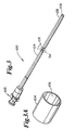
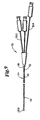
- Fig. 1 shows a perspective view of a catheter assembly 30 in accordance with the present invention.
- Catheter assembly 30 is used in catheter procedures for accessing targeted anatomical regions through the alimentary canal.
- the present invention incorporates features which allow rapid exchange of catheter by a single operator.
- the catheter of the present invention allows shorter length guide wires to be used, resulting in procedures which require less medical personnel, are less time consuming, and less costly. Additionally, the present invention is adaptable to most catheter devices used for catheter procedures within the alimentary canal.
- Catheter assembly 30 includes a catheter hub assembly 32 and a catheter 34, having a guide wire 36 passing through a portion thereof.
- Catheter 34 includes a shaft 38, which in general terms has a proximal end 40, a U-channel 42, a distal tip region 44, a distal end 46 and various lumens described in greater detail below.
- Catheter hub assembly 32 is operably connected to proximal end 40 of shaft 38.
- Catheter hub assembly 32 is preferably configured to couple to ancillary devices allowing access to a lumen within shaft 38.
- Shaft 38 is a generally tubular shaped member having a generally uniform outer shape at proximal end 40. Shaft 38 may be sized for slidable passage through the lumen of an endoscope (not shown). Shaft 38 is preferably formed in an extrusion process. Shaft 38 may be formed of an extruded polymeric material. In one embodiment, the preferred polymeric material is polytetrafluoroethylene, polyether block amide, nylon or a combination or blend of these. Catheters which are contemplated include, but are not limited to, cannulas, sphincterotomes, cytology devices, and devices for stone retrieval and stent placement.
- shaft 38 further includes a distal taper 48 which tapers to distal tip region 44.
- tip region 44 may include high contrast, color coded distal markers 50.
- distal end 46 may be radiopaque for fluoroscopic visualization of distal tip region 44 during a catheter procedure. It should be understood, however, that these additional features are in no way required elements.
- U-channel 42 of shaft 38 extends between a first, proximal channel end 52 and a second, distal channel end 54.
- U-channel 42 serves to contain, but not necessarily constrain, guide wire 36, between channel proximal end 52 and channel distal end 54.
- the term "U-channel” refers to a channel shape that allows radial removal of guide wire 36 from the channel 42, and need not be strictly in the shape of the letter U.
- Channel 42 in the preferred embodiment is sufficiently large to allow unhindered radial guide wire 36 movement out of channel 42.
- the channel walls and radial opening are substantially equal to or slightly larger than the diameter of a guide wire lumen, described in greater detail below.
- proximal channel end 52 may be located at any location distal of proximal end 40 of shaft 38
- channel distal end 54 is preferably located between 10 and 40 cm from distal end 46 of catheter shaft 38.
- Fig. 1A which is a cross-sectional view of shaft 38 taken along line 1A-1A at a location proximal of channel proximal end 52, shaft 38 includes ancillary lumen 56, ancillary lumen 58 and guide wire lumen 60.
- Ancillary lumen 56 and ancillary lumen 58 extend longitudinally between proximal end 40 and distal end 46 of shaft 38.
- Ancillary lumen 56 and ancillary lumen 58 may be injection lumens, allowing for high contrast media flow capability for bubble-free opacification and for excellent visualization of a desired anatomical region. Additionally or alternatively, ancillary lumen 56 and/or ancillary lumen 58 may be used for or as part of other ancillary devices, such as a cutting wire lumen or a retrieval balloon lumen.
- Guide wire lumen 60 extends longitudinally between proximal end 40 and distal end 46 of shaft 38 in the preferred embodiment. Further, guide wire lumen 60 is sized to receive guide wire 36. Guide wire lumen 60 may be a tubular member which is extruded integral catheter shaft 38, or alternatively, guide wire lumen 60 may be a separate tubular member which is coupled to catheter shaft 38. Although in one preferred embodiment the guide wire lumen 60 is a tubular member which is located proximate distal end 46 of catheter shaft 38, it is recognized that guide wire lumen 60 may be formed anywhere along shaft 38, may be an extension of shaft 38 coupled to distal end 46, or guide wire lumen 60 may run the entire length of shaft 38.
- Guide wire 36 may access guide wire lumen 60 at a point proximal channel distal end 54.
- Guide wire 36 extends within channel 42 to channel distal end 54, continuing within guide wire lumen 60 through distal tip region 44, and exiting through an opening in distal end 46.
- a section of catheter shaft 38 having U-channel 42 is shown.
- the embodiment shown also includes ancillary lumens 56 and 58.
- Sections of shaft 38 proximate the channel proximal end 52 and distal channel distal end 54 contain guide wire lumen 60 in communication with U-channel 42.
- U-channel 42 has an interior, closed-side geometry, substantially the same as the geometry of guide wire lumen 60. Further, U-channel 42 walls are spaced further than a diameter of guide wire 36 such that guide wire 36 moves freely into and out of U-channel 42.
- Catheter shaft 38 can be configured such that U-channel 42 is defined separately from guide wire lumen 60.
- guide wire lumen 60 is divided into two sections; a first section extending between proximal end 40 of shaft 38 and channel proximal end 52; and a second portion extending between channel distal end 54 and distal end 46 of shaft 38.
- the shaft can be configured to define guide wire lumen 60 as extending longitudinally between proximal end 40 and distal end 46 of shaft 38.
- guide wire lumen 60 is integral with U-channel 42.
- guide wire lumen 60 defines a portion of U-channel 42 such that spacing between outer walls of U-channel 42 is equal to a diameter of guide wire lumen 60. Regardless of how guide wire lumen 60 and U-channel 42 are defined, U-channel 42 provides for access to guide wire lumen 60 at channel distal end 54. In this regard, channel distal end 54 can be enlarged to more easily direct guide wire 36 into guide wire lumen 60.
- Guide wire lumen 60 and U-channel 42 allow rapid exchange of catheter assembly 30 when an alternative catheter is necessary during a certain medical procedure. Shorter length guide wires may be used since guide wire 36 does not pass through shaft proximal end 40 and hub assembly 32, but rather exits the catheter shaft 38 at U-channel 42 located substantially distal from proximal end 40.
- the unique catheter construction in accordance with the present invention will reduce catheter therapeutic and diagnostic procedure time since catheter device exchanges may be performed relatively more easily and quickly by a single operator. Additional personnel and time associated with maintaining the placement of a conventional (approximately 400 cm) guide wire within the targeted anatomical region is eliminated, reducing the overall costs of the procedure.
- FIG. 2A illustrates catheter shaft 38 having ancillary lumens 54 and 56, U-channel 42, and guide wire 36 within U-channel 42. Further, shaft 38 is shown within a first size endoscope working channel 70.
- guide wire 36 is effectively radially constrained by small sized working channel 70 that closely surrounds U-channel 42.
- Fig. 2B illustrates catheter containment within a second size working channel 72, slightly larger than the working channel 70 of Fig. 2A.
- guide wire 36 is able to move out of U-channel 42 to a position denoted with dashed lines at 80.
- Fig. 2C shows shaft 38 contained within a third, even larger sized working channel 74.
- Guide wire 36 is able to move completely out of U-channel 42 to position 82 shown with dashed lines.
- Fig. 2D demonstrates catheter shaft 38 within a fourth size working channel 76. In this even larger working channel, guide wire 36 lies within an even larger cross-sectional area, and is able to move to a position shown in FIG. 2D with dashed lines at 84.
- an exchange sheath having a sufficiently small inner diameter so as to constrain guide wire movement to within the catheter U-channel 42 is employed with the preferred embodiment.
- an endoscope exchange sheath in accordance with the preferred embodiment allows for use of a radially accessible guide wire, which is longitudinally aligned with the catheter, while presenting a circular profile to an endoscope and mitigating guide wire pinching problems between the catheter and the endoscope working channel wall.
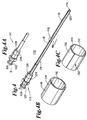
- an endoscope exchange sheath assembly 100 having sheath hub assembly 102 and a sheath 104 is shown.
- the sheath 104 includes a lumen 106 and a distal end 108.
- Fig. 3A shows a section of sheath 104, having lumen 106 for receiving a catheter.
- catheter 34 is fed through lumen 106 of sheath 104 such that sheath 104 encompasses guide wire 36 within U-channel 42.
- Sheath 104 is adapted to be disposed within an endoscope working channel, thereby providing a smaller diameter channel than that of the surrounding endoscope working channel constraining the guide wire 34 (Fig. 1) to the U-channel 50 (Fig. 1), and mitigating the potential problems shown in Figs. 2C and 2D.
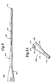
- Sheath assembly 110 includes a two-piece hub assembly 112 and a sheath 114 defining lumen 116 and having slit 118 extending longitudinally over its length, terminating at distal end 120. Slit 118 in sheath 114 is shown in more detail in Fig. 4B.
- two-piece hub assembly 112 has a proximal hub portion 122 and a distal hub portion 124, having a proximal slit 126 and a distal slit 128, respectively.
- Sheath slit 118 is in communication with hub slits 126 and 128, allowing a guide wire (not shown) to be radially slid into or out of sheath assembly 110.
- Proximal hub portion 122 is shown unlocked (position "A") in Fig. 4, aligning hub proximal slit 126 with hub distal slit 128 and sheath alit 118, providing a continuous slit for guide wire radial movement into and out of the sheath assembly 110.
- Proximal hub portion 122 is shown locked, in position "B", in Fig. 4A, whereby proximal hub slit 126 is rotated with respect to distal hub slit 128, preventing a guide wire (not shown) within hub assembly 112 from being moved radially out of hub assembly 112.
- Proximal hub portion 122 is set to position B (Fig. 4A) when radial guide wire movement is not desired.
- Fig. 4C illustrates a portion of an alternate embodiment sheath 130 having a lumen 132, a sheath wall opening 134 and sheath wall overlap 136.
- a guide wire (not shown) is able to be slid out of lumen 132 of sheath 130 by maneuvering the guide wire into sheath wall opening 134 and through overlap 136.
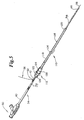
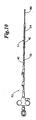
- catheter assembly 30 depicted in Fig. 1 is shown inserted within endoscope exchange sheath assembly 110 depicted in Fig. 4. More particularly, catheter 34 is inserted through slitted sheath assembly 110, extending distally out sheath distal end 120.
- Guide wire 36 (shown partially in Fig. 5) is positioned within U-channel 42 of catheter 34, along guide wire lumen 60 (Fig. 1B), and extends from shaft distal end 46. Further, guide wire 36 is engaged by hub assembly 112. More particularly, guide wire 36 passes within and is engaged by proximal slit 126 and distal slit 128 of hub assembly 112.
- Sheath proximal hub portion 122 having proximal slit 126, is shown in locked position relative to sheath distal hub portion 124, having distal slit 128.
- hub assembly 112 of sheath assembly 110 prevents radial withdrawal of guide wire 36, otherwise inserted in U-channel 42 of catheter 34, from distal the channel proximal end 52.
- Fig. 6 a section of Fig. 5 is shown in detail, having endoscope sheath 114 containing catheter shaft 38, which further maintains guide wire 36 within U-channel 42.
- sheath 114 is able to constrain movement of guide wire 36 from U-channel 42 when sheath 114 is within a larger endoscope working channel, for example as illustrated in Figs. 2C and 2D.
- the sheath 114 embodiment illustrated in Fig. 6 includes longitudinal slit 118, allowing guide wire 36 to be peeled from catheter shaft 38 and endoscope sheath 114.
- U-channel 42 is sized larger than guide wire 36 such that guide wire 36 can displace radially from U-channel 42.
- Sheath 114 prevents undesired displacement of guide wire 36 from U-channel 42 under normal operating conditions. However; if adequate radial force is placed on guide wire 36 by an operator, guide wire 36 will separate sheath 114 along slit 118 such that guide wire 36 is displaced from sheath 114 and U-channel 42.
- guide wire 36 is shown inserted within catheter assembly 30 of Fig. 1, which is inserted through endoscope sheath assembly 110 of Fig. 4, which is in turn within an endoscope 150.
- Sheath assembly 110 includes sheath 114 that has slit 118 and two-piece hub assembly 112, shown at a locked position "B" (also in Fig. 4A). Having hub assembly 112 locked prevents guide wire 36 from moving radially out of sheath 114 through slit 118.
- Guide wire 36 can be restrained from longitudinal movement by applying finger pressure on the guide wire 36 against hub assembly 112.
- endoscope 150 and sheath assembly 110 of Fig. 7 are shown without the catheter assembly 30 inserted, as after catheter withdrawal.
- Sheath hub assembly 112 is shown in unlocked position at "A" (also in Fig. 4). Having hub assembly 112 unlocked allows radial movement of guide wire 36 out of sheath 114 through slit 118, but such movement may be restrained by trapping guide wire 36 against the outside of sheath 114 using one finger, providing ease of guide wire 36 control during catheter exchanges.
- an endoscope 150 is first introduced into the mouth of a patient and is guided through the patient's alimentary canal. Specifically, endoscope 150 is guided down the esophagus, through the stomach, past the pyloric sphincter of the stomach and into the duodenum. Endoscope 150 has a lumen extending longitudinally between its proximal end and the distal end.
- Endoscope 150 is guided through the alimentary canal until a distal end (not shown) of endoscope 150 is proximate the target area within the anatomy to receive treatment.
- endoscope 150 is guided into the duodenum until the opening at the distal end of the endoscope 150 is proximate the papilla of vater.
- the papilla of vater is located between the sphincter of oddi, which leads to the common bile duct, hepatic, and pancreatic ducts.
- the proximal end (shown in Figs. 7 and 7A) of endoscope 150 extends and remains outside the mouth of the patient.
- catheter assembly 30 is prepared for insertion into the endoscope.
- guide wire 36 is fed into the guide wire lumen 60 (Figs. 1A-1C) of shaft 38. More particularly, a distal end of guide wire 36 is placed within U-channel 42, distal the channel proximal end 52. The guide wire 36 is then fed to channel distal end 54 (Fig. 1) into guide wire lumen 60. Finally, guide wire 36 is fed through shaft 38 to distal tip region 40 (Fig. 1).
- catheter 32 is then inserted directly into endoscope 150 working channel. This method may be practiced with an endoscope having a sufficiently small working channel inside diameter, as illustrated in Fig. 2A, to constrain guide wire 36 movement without a sheath.
- catheter assembly 30, threaded with guide wire 36 is inserted into sheath assembly 110, thereby constraining guide wire 36 from slipping radially out of U-channel 42. More particularly, catheter 34 is inserted into endoscope 150 working channel, but leaving channel proximal end 52 proximate sheath hub assembly 112, and leaving a portion of guide wire 36 extending from the channel proximal end 52 as well.
- sheath hub assembly 112 includes hub slits 126 and 128 which receive a portion of guide wire 36.
- hub assembly 112 is locked, preventing unwanted radial guide wire 36 movement.
- the loading of guide wire 34 into catheter shaft 38 and catheter shaft 38 into sheath assembly 110 is done prior to inserting endoscope 150 into a patient (not shown).
- Endoscope sheath 114 containing catheter shaft 38, is inserted into endoscope 150 working channel. Endoscope sheath 114 serves to constrain radial guide wire 36 movement over the approximate length of U-channel 42. Catheter shaft 38 and sheath 114 are inserted together into endoscope 150 until both are near a distal end (not shown) of endoscope 150. Catheter shaft 38 and sheath 114 may be, either or both, advanced until exiting the distal end of endoscope 150.
- guide wire 36 is advanced until guide wire 36 distal tip is positioned within the target area in the biliary tree (including the common bile, hepatic or pancreatic ducts).
- the distal tip of guide wire 36 may be guided through the orifice leading to the papilla of vater for access to the biliary tree.
- Catheter shaft 38 may then be advanced over guide wire 36, tracking catheter assembly 30, until catheter distal tip region 44 (Fig. 1) exits distal end of endoscope 150 and is positioned within the desired duct.
- guide wire 36 and catheter assembly 30 are advanced together until catheter distal end 42 (Fig. 1) is positioned at the target area. It is also recognized that the catheter could be first advanced to near the target area, followed by inserting the guide wire when needed to advance the catheter further.
- catheter procedures including injecting contrast media, such as radiopaque dye, through ancillary lumens 56 or 58 (Fig. 1A-1C) into the common bile duct for visualization of the duct, can be performed.
- catheter assembly 30 can be exchanged or removed from endoscope 150, leaving guide wire 36 in position for other catheter procedures.
- Catheter assembly 30 and sheath assembly 110 may also be removed together.
- One method of withdrawing catheter 34 from endoscope 150 is possible using either a slitted/overlapped endoscope sheath 114 as depicted in Figs. 4 through 5C, or a sheath 104 without a slit as depicted in Figs. 3 through 3A.
- guide wire 36 is held to prevent longitudinal movement while catheter 34 is retracted within endoscope sheath 114 (or 104).
- Catheter 34 retraction leaving the guide wire 36 in position within the patient is enabled by U-channel 42 being radially open to guide wire 36 removal in catheter shaft 38. Once catheter retraction has brought channel distal end 54 (Fig.
- the distal end of the endoscope can include an elevator which could be utilized to lock the distal end of the guide wire in position while the catheter is removed.
- Exchange of endoscope assembly 110 may be desired, as when a stent (not shown) is to be advanced over guide wire 36, and the stent has a larger outside diameter than can be accommodated by the sheath 114.
- One method of exchanging an endoscope sheath assembly 110 may be used where sheath 114 is slitted as in Fig. 4B, or overlapped, as in sheath 130 in Fig. 4C. Referring to Fig. 7A, two-piece hub assembly 112 is turned to the unlocked position "A" (also shown in Fig. 4). Guide wire 36 is pulled radially away from sheath hub assembly 112 and through slit 118 in sheath 114.
- Guide wire 36 is then held, preferably against some portion of endoscope 150, to prevent guide wire 36 from being dislodged from position within the patient.
- Sheath 114 is retracted from endoscope 150, guide wire 36 being “peeled” away from sheath 114. Sheath retraction is continued until sheath 114 is completely outside of endoscope 150 and over guide wire 36.
- guide wire 36 is within endoscope 150 working channel, and stents, catheters, and endoscope sheaths may be advanced over guide wire 36.
- FIG. 7 and 7A Another method of exchanging both endoscope sheath assembly 110 and catheter assembly 30 may be used where the sheath 114 is slitted as in Fig. 4B, or overlapped, as in sheath 130 in Fig. 4C.
- two-piece hub assembly 112 is turned to the unlocked position "A" (Fig. 7A).
- Guide wire 36 is pulled radially away from U-channel 42 of catheter 34, from hub assembly 112 and through slit 118 in sheath 114.
- Guide wire 36 is then held, preferably against some portion of endoscope 150, to prevent guide wire 36 from being dislodged from position within the patient.
- Sheath 114 and catheter 34 are retracted from endoscope 150, with guide wire 36 being “peeled” away from sheath 114. Sheath assembly 110 and catheter assembly 30 retraction are continued until sheath 114 and catheter 34 are completely outside of endoscope 150 and over guide wire 36. At this point, guide wire 36 remains in a position within endoscope 150 and patient. A single operator can access a small portion of guide wire 36 between distal end 46 (Fig. 1) of catheter 34 to hold guide wire 36 in place while catheter assembly 30 is completely removed or disengaged from guide wire 36.
- sheath assembly 110 has been described as including a two-piece hub assembly 112 in conjunction with sheath 114, other assemblies may be used.
- sheath assembly 160 includes an introducer 162, an attachment means 164 and a sheath 166.
- sheath 166 defines a lumen (not shown) and includes a slit 168 extending longitudinally over its length, terminating at a distal end 170.
- Sheath 166 is generally identical to sheath 104 and sheath 114 previously described.
- Introducer 162 is attached to sheath 166 by attachment means 164 such that lumen (not shown) of sheath 166 is in fluid communication with an interior portion of introducer 162.
- attachment means 164 is a flexible membrane which seals sheath 166 to introducer 162.
- other forms of attachment such as an adhesive or frictional engagement between introducer 162 and sheath 166 may also be useful.
- Introducer 162 is shown in greater detail.
- Introducer 162 is a funnel-shaped device including a horn 172 and a neck 174.
- horn 172 and neck 174 are integrally formed as a singular body.
- Born 172 is preferably a conically-ahaped body having an outer wall 176.
- Outer wall 176 defines an interior space and includes a guide wire-receiving notch 180 formed near proximal end 182 of horn 172.
- Guide wire-receiving notch 180 is preferably J-shaped and includes an entry end 184 and a locking end 186. As shown in Fig. 8A, entry end 184 is open at proximal end 182 of horn 172. Conversely, locking end 186 is closed. communication with interior space of horn 172.
- horn 172 and neck 174 are formed of a plastic material. Alternatively, any other semi-rigid or rigid, surgically-safe material may be used.
- catheter assembly 34 (Fig. 1) is inserted within sheath assembly 160. More particularly, distal end 46 (Fig. 1) of catheter shaft 38 (Fig. 1), including guide wire 36 (Fig. 1) is placed within horn 172 of introducer 162. The conical shape of horn 172 assists in directing distal end 46 of catheter shaft 38, including guide wire 36, into passage 188 of neck 174.
- Catheter shaft 38 continues forward within lumen (not shown) of sheath 166 until distal end 46 of catheter shaft 38 extends from distal end 170 of sheath 166.
- a proximal end of guide wire 36 (Fig. 1) is maintained within guide wire-receiving notch 180. More particularly, a portion of guide wire 36 is forced by an operator through entry end 184 of guide wire-receiving notch 180 and forced within locking end 186 thereof.
- locking end 186 preferably has a diameter slightly smaller than that of guide wire 36.
- guide wire 36 can easily be released from guide wire-receiving notch 180 by sliding guide wire 36 from locking end 186 and out of entry end 184.
- sheath assembly 160 functions in a manner highly similar to sheath assembly 100 and sheath assembly 110 previously described.
- catheter assembly 30 is used as a rapid exchange retrieval balloon system used for stone retrieval or isolated visualization techniques.
- Ancillary lumens 56 and 58 form a portion of retrieval balloon catheter 300 having a balloon 302 located at its distal end, and for passage of dye injection apparatus 304.
- the guide wire lumen 60 (Figs. 1A-1C) may be accessed using conventional guide wire techniques through the proximal end 48 of catheter 34 or using rapid exchange techniques, via U-channel 42.
- the rapid exchange catheter assembly 30 design of the present invention may be used for other alimentary canal catheter applications, such as a rapid exchange sphincterotome used for endoscopic retrograde sphincterotomy, shown using a cutting wire apparatus 310.
- the guide wire lumen 60 may be accessed by conventional guide wire techniques at the proximal end 48 of catheter 34, or alternatively, using the rapid exchange technology of the present invention, including U-channel 42.
- the rapid exchange catheter of the present invention is preferably a multi-lumen catheter.
- the guide wire lumen is isolated from the ancillary lumens allowing for exceptional contrast flow for high quality opacification without the need for guide wire removal.
- Treatment and therapeutic devices such as retrieval balloon catheters or catheters having cutting apparatus may be included, without interference of a guide wire located within the guide wire lumen. Additionally, isolation of the guide wire lumen from the contrast lumen minimizes the risk of bubble formation during contrast flow and produces a contrast-free guide wire surface for efficient device exchanges.
- the rapid exchange catheter of the present invention has been preferably described as being a biliary catheter, other applications are also envisioned.
- the catheter of the present invention can be used with biopsy, metal stent placement, plastic stent placement, snares, baskets, etc.
- the catheter of the present invention may have vascular applications, where a guide catheter is substituted for the endoscope to constrain the guide wire.
Description
Claims (10)
- A rapid exchange catheter for use in a biliary procedure endoscope (150), the catheter including a shaft (38) having a proximal end (40) and a distal end (46),
a guide wire lumen (60) carried by the shaft (38) extending longitudinally between the proximal end (40) and the distal end (46) of the shaft (38);
a channel (42) for accessing the guide wire lumen (60) from a location exterior to the shaft (38), wherein the channel (42) extends longitudinally along the shaft (38) from a first end (54) to a second end (52), the first end (54) being located between 10 and 40 cm from the distal end (46) of the shaft (38) and the second end (52) of the channel (42) being located proximal of the first end (54);
characterized in that the channel (42) length from the first end (54) to the second end (52) is such that when the shaft (38) is inserted through an endoscope being at least 150 cm long, during a biliary treatment of a patient performed by access via the alimentary canal, the channel (42) extends out of the patient, while the distal end (46) of the shaft (38) extends out of a distal opening of the endoscope. - The catheter of claim 1 wherein the guide wire lumen (60) is formed integral with the shaft (38).
- The catheter of claim 1, further including an ancillary lumen (58) .extending between the catheter proximal end and the catheter distal end.
- The catheter of claim 1, wherein the guide wire lumen (60) is sized to receive a guide wire (38) having a diameter; at least a portion of the channel (42) having.a width greater than the diameter of the guide wire (38) to allow radial guide wire movement within the channel (42).
- The catheter of claim 4, wherein the channel (42) is formed integral with the guide wire lumen (60), such that the channel (42) has a width approximately equal to a diameter of the guide wire lumen (60).
- The catheter of claim 1 wherein the channel (42) for accessing the guide wire lumen (60) includes a first and a second opening located respectively, to the first end (54) of the channel (42) and the second end (52) of the channel, wherein the first opening and the second opening are enlarged.
- A rapid exchange biliary catheter system for use in a biliary procedure endoscope (150), the catheter system comprising:a) a rapid exchange biliary catheter (34) for use in a biliary procedure endoscope (150), the catheter having:wherein the channel (42) length from the first end (54) to the second end (52) is such that when the shaft is inserted through an endoscope being at least 150 cm long during a biliary treatment of a patient performed by access via the alimentary canal, the channel (42) extends out of the patient, while the distal end (46) of the shaft (38) extends out of a distal opening of the endoscope; anda shaft (38) having a proximal end (40) and a distal end (46);a guide wire lumen (60) carried by the shaft (38) extending longitudinally between the proximal end (40) and the distal end (46) of the shaft (38); anda channel (42) for accessing the guide wire lumen (60) from a location exterior to the shaft (38), wherein the channel (42) extends longitudinally along the shaft (38) from a first end (54) to a second end (52), the first end (54) being located between 10 and 40 cm from the distal end (46) of the shaft (38) and the second end (52) of the channel (42) being located proximal of the first end (54);b) an endoscope sheath assembly (102) having a proximal end and a distal end, which endoscope sheath assembly (102) includes a sheath (104) at the distal end adapted to receive the catheter (34), the endoscope sheath assembly (102) further including a hub (112) at the proximal end.
- The system of claim 7, wherein the sheath (114) includes a lumen therethrough defining a sheath (114) wall, the sheath (114) wall having a means for allowing radial removal of a guide wire (38) contained therein.
- The system of claim 8, wherein the means for allowing radial removal of a guide wire (38) includes a longitudinal slit in the sheath (114) wall.
- The system of claim 8, wherein the means for allowing radial removal of a guide wire (38) includes a circumferentially overlapping sheath (114) wall.
Applications Claiming Priority (5)
| Application Number | Priority Date | Filing Date | Title |
|---|---|---|---|
| US926200 | 1986-11-03 | ||
| US2523596P | 1996-09-13 | 1996-09-13 | |
| US25235P | 1996-09-13 | ||
| US08/926,200 US6007522A (en) | 1996-09-13 | 1997-09-09 | Single operator exchange biliary catheter |
| PCT/US1997/016020 WO1998010821A1 (en) | 1996-09-13 | 1997-09-10 | Single operator exchange biliary catheter |
Publications (2)
| Publication Number | Publication Date |
|---|---|
| EP0948372A1 EP0948372A1 (en) | 1999-10-13 |
| EP0948372B1 true EP0948372B1 (en) | 2005-11-16 |
Family
ID=26699480
Family Applications (1)
| Application Number | Title | Priority Date | Filing Date |
|---|---|---|---|
| EP97940999A Expired - Lifetime EP0948372B1 (en) | 1996-09-13 | 1997-09-10 | Single operator exchange biliary catheter |
Country Status (9)
| Country | Link |
|---|---|
| US (1) | US6007522A (en) |
| EP (1) | EP0948372B1 (en) |
| JP (1) | JP4443631B2 (en) |
| AU (1) | AU732412B2 (en) |
| CA (1) | CA2265491C (en) |
| DE (1) | DE69734672T2 (en) |
| ES (1) | ES2252793T3 (en) |
| HK (1) | HK1025058A1 (en) |
| WO (1) | WO1998010821A1 (en) |
Cited By (3)
| Publication number | Priority date | Publication date | Assignee | Title |
|---|---|---|---|---|
| US8211087B2 (en) | 2003-07-31 | 2012-07-03 | Cook Medical Technologies Llc | Distal wire stop |
| US8292872B2 (en) | 2007-06-29 | 2012-10-23 | Cook Medical Technologies Llc | Distal wire stop having adjustable handle |
| US8512389B2 (en) | 2003-07-31 | 2013-08-20 | Cook Medical Technologies, LLC | System and method for introducing multiple medical devices |
Families Citing this family (111)
| Publication number | Priority date | Publication date | Assignee | Title |
|---|---|---|---|---|
| US6096009A (en) * | 1996-09-13 | 2000-08-01 | Boston Scientific Corporation | Guidewire and catheter locking device and method |
| US6520951B1 (en) | 1996-09-13 | 2003-02-18 | Scimed Life Systems, Inc. | Rapid exchange catheter with detachable hood |
| US6346093B1 (en) | 1996-09-13 | 2002-02-12 | Scimed Life Systems, Inc. | Single operator exchange biliary catheter with common distal lumen |
| US6582401B1 (en) | 1996-09-13 | 2003-06-24 | Scimed Life Sytems, Inc. | Multi-size convertible catheter |
| US6606515B1 (en) | 1996-09-13 | 2003-08-12 | Scimed Life Systems, Inc. | Guide wire insertion and re-insertion tools and methods of use |
| US5921971A (en) | 1996-09-13 | 1999-07-13 | Boston Scientific Corporation | Single operator exchange biliary catheter |
| US7008412B2 (en) | 1998-01-06 | 2006-03-07 | Cathlogic, Inc. | Subcutaneous port catheter system and associated method |
| US20020091362A1 (en) * | 1998-01-06 | 2002-07-11 | Maginot Thomas J. | Medical procedure using catheter system having removability feature |
| US6796976B1 (en) * | 1998-03-06 | 2004-09-28 | Scimed Life Systems, Inc. | Establishing access to the body |
| KR19990081473A (en) * | 1998-04-30 | 1999-11-15 | 안정오 | Bile drainage tube |
| US6743218B2 (en) | 1999-01-15 | 2004-06-01 | Cathlogic, Inc. | Retractable catheter systems and associated methods |
| US6475207B1 (en) | 1999-01-15 | 2002-11-05 | Maginot Catheter Technologies, Inc. | Retractable catheter systems and associated methods |
| US6585705B1 (en) * | 1999-01-15 | 2003-07-01 | Maginot Catheter Technologies, Inc. | Retractable catheter systems |
| US20050059925A1 (en) * | 1999-01-15 | 2005-03-17 | Maginot Thomas J. | Catheter systems and associated methods |
| US20050096609A1 (en) * | 1999-01-15 | 2005-05-05 | Maginot Thomas J. | Methods of performing medical procedures with catheter systems having movable member |
| US6287329B1 (en) * | 1999-06-28 | 2001-09-11 | Nitinol Development Corporation | Stent keeper for a self-expanding stent delivery system |
| US6605075B1 (en) * | 1999-12-21 | 2003-08-12 | Ethicon, Inc. | Flushable hub |
| US7811250B1 (en) | 2000-02-04 | 2010-10-12 | Boston Scientific Scimed, Inc. | Fluid injectable single operator exchange catheters and methods of use |
| AU2001233526A1 (en) * | 2000-02-11 | 2001-08-20 | Novo Rps Ulc | Stent delivery system and method of use |
| US20040098085A1 (en) * | 2000-02-11 | 2004-05-20 | Ricci Donald R. | Stent delivery system and method of use |
| JP4731089B2 (en) | 2000-05-18 | 2011-07-20 | ウィルソン−クック メディカル インコーポレイテッド | Medical device with improved guidewire access |
| US6475184B1 (en) * | 2000-06-14 | 2002-11-05 | Scimed Life Systems, Inc. | Catheter shaft |
| US6592549B2 (en) * | 2001-03-14 | 2003-07-15 | Scimed Life Systems, Inc. | Rapid exchange stent delivery system and associated components |
| US6764484B2 (en) * | 2001-03-30 | 2004-07-20 | Scimed Life Systems, Inc. | C-channel to o-channel converter for a single operator exchange biliary catheter |
| US6827718B2 (en) | 2001-08-14 | 2004-12-07 | Scimed Life Systems, Inc. | Method of and apparatus for positioning and maintaining the position of endoscopic instruments |
| US20030060842A1 (en) * | 2001-09-27 | 2003-03-27 | Yem Chin | Method and apparatus for measuring and controlling blade depth of a tissue cutting apparatus in an endoscopic catheter |
| WO2003039626A2 (en) | 2001-11-08 | 2003-05-15 | Houser Russell A | Rapid exchange catheter with stent deployment, therapeutic infusion, and lesion sampling features |
| AU2003223749A1 (en) * | 2002-04-25 | 2003-11-10 | The Board Of Trustees Of The Leland Stanford Junior University | Expandable guide sheath and apparatus and methods using such sheaths |
| US7534223B2 (en) * | 2002-10-08 | 2009-05-19 | Boston Scientific Scimed, Inc. | Catheter with formed guide wire ramp |
| US7037293B2 (en) * | 2002-11-15 | 2006-05-02 | Boston Scientific Scimed, Inc. | Rapid exchange catheter with depressable channel |
| US6893393B2 (en) | 2003-02-19 | 2005-05-17 | Boston Scientific Scimed., Inc. | Guidewire locking device and method |
| US20050043669A1 (en) * | 2003-08-18 | 2005-02-24 | Codman & Shurtleff, Inc. | Trimmable sensing catheter |
| DE602004028382D1 (en) * | 2003-10-03 | 2010-09-09 | Medtronic Inc | ADVANCED GUIDE SLIDE AND DEVICE |
| US7867271B2 (en) * | 2003-11-20 | 2011-01-11 | Advanced Cardiovascular Systems, Inc. | Rapid-exchange delivery systems for self-expanding stents |
| US7162030B2 (en) * | 2003-12-23 | 2007-01-09 | Nokia Corporation | Communication device with rotating housing |
| US7887574B2 (en) * | 2003-12-23 | 2011-02-15 | Scimed Life Systems, Inc. | Stent delivery catheter |
| US7468070B2 (en) * | 2004-01-23 | 2008-12-23 | Boston Scientific Scimed, Inc. | Stent delivery catheter |
| EP1737335B1 (en) | 2004-03-23 | 2013-05-15 | Boston Scientific Limited | In-vivo visualization system |
| US7922654B2 (en) | 2004-08-09 | 2011-04-12 | Boston Scientific Scimed, Inc. | Fiber optic imaging catheter |
| US11819192B2 (en) | 2004-03-23 | 2023-11-21 | Boston Scientific Scimed, Inc. | In-vivo visualization system |
| US8425539B2 (en) | 2004-04-12 | 2013-04-23 | Xlumena, Inc. | Luminal structure anchoring devices and methods |
| US7217246B1 (en) | 2004-06-17 | 2007-05-15 | Biomet Sports Medicine, Inc. | Method and apparatus for retaining a fixation pin to a cannula |
| US7828751B2 (en) * | 2004-06-17 | 2010-11-09 | Biomet Sports Medicine, Llc | Method and apparatus for retaining a fixation pin to a cannula |
| EP1771221B1 (en) | 2004-07-29 | 2010-09-22 | Wilson-Cook Medical Inc. | Catheter with splittable wall shaft |
| ATE481999T1 (en) * | 2004-07-29 | 2010-10-15 | Wilson Cook Medical Inc | CATHETER SHAFT WITH SEPARABLE WALL |
| US7993350B2 (en) | 2004-10-04 | 2011-08-09 | Medtronic, Inc. | Shapeable or steerable guide sheaths and methods for making and using them |
| WO2006062996A2 (en) | 2004-12-08 | 2006-06-15 | Kenneth Binmoeller | Method and apparatus for performing needle guided interventions |
| US8480629B2 (en) | 2005-01-28 | 2013-07-09 | Boston Scientific Scimed, Inc. | Universal utility board for use with medical devices and methods of use |
| US8562566B2 (en) * | 2005-02-28 | 2013-10-22 | Boston Scientific Scimed, Inc. | Stent delivery and guidewire guidance system |
| US20060235269A1 (en) * | 2005-04-15 | 2006-10-19 | The University Of Chicago | Method, apparatus and kit for bile or pancreatic duct endoscopy |
| US8784437B2 (en) | 2005-06-09 | 2014-07-22 | Xlumena, Inc. | Methods and devices for endosonography-guided fundoplexy |
| US8777967B2 (en) | 2005-06-09 | 2014-07-15 | Xlumena, Inc. | Methods and devices for anchoring to tissue |
| US7765014B2 (en) * | 2005-08-16 | 2010-07-27 | Medtronic, Inc. | Apparatus and methods for delivering transvenous leads |
| WO2007055032A1 (en) * | 2005-11-14 | 2007-05-18 | Olympus Medical Systems Corp. | Method of endoscopical diagnosis or treatment and medical device |
| JP4954571B2 (en) * | 2006-02-20 | 2012-06-20 | 株式会社カネカ | Long medical device holding system and method |
| US20070244356A1 (en) * | 2006-04-17 | 2007-10-18 | Boston Scientific Scimed, Inc. | Elongate medical devices having an improved distal profile for use with an endoscope |
| US8926499B2 (en) * | 2006-04-17 | 2015-01-06 | Boston Scientific Scimed, Inc. | Catheter for use with an endoscope |
| US9149173B2 (en) * | 2006-06-20 | 2015-10-06 | Boston Scientific Scimed, Inc. | Medical device for use in endoscopic procedure |
| US9889275B2 (en) | 2006-06-28 | 2018-02-13 | Abbott Laboratories | Expandable introducer sheath to preserve guidewire access |
| US20180140801A1 (en) * | 2006-06-28 | 2018-05-24 | Abbott Laboratories | Expandable introducer sheath to preserve guidewire access |
| US8372000B2 (en) | 2007-01-03 | 2013-02-12 | Boston Scientific Scimed, Inc. | Method and apparatus for biliary access and stone retrieval |
| EP2117633B1 (en) * | 2007-02-05 | 2016-01-06 | Boston Scientific Limited | System with catheter system and an adaptor comprising a friction reducing sleeve |
| US7815601B2 (en) * | 2007-02-05 | 2010-10-19 | Boston Scientific Scimed, Inc. | Rapid exchange enteral stent delivery system |
| US8480570B2 (en) * | 2007-02-12 | 2013-07-09 | Boston Scientific Scimed, Inc. | Endoscope cap |
| US8758421B2 (en) * | 2008-01-30 | 2014-06-24 | Boston Scientific Scimed, Inc. | Medical systems and related methods |
| US8388521B2 (en) | 2008-05-19 | 2013-03-05 | Boston Scientific Scimed, Inc. | Integrated locking device with active sealing |
| US8343041B2 (en) | 2008-05-19 | 2013-01-01 | Boston Scientific Scimed, Inc. | Integrated locking device with passive sealing |
| US20090287052A1 (en) * | 2008-05-19 | 2009-11-19 | Boston Scientific Scimed, Inc. | Biopsy Cap Attachment and Integrated Locking Device |
| US20110105984A1 (en) * | 2008-04-02 | 2011-05-05 | Patel Aalpen A | Dual lumen dialysis catheter with internally bored or externally-grooved small bore |
| US9421065B2 (en) | 2008-04-02 | 2016-08-23 | The Spectranetics Corporation | Liquid light-guide catheter with optically diverging tip |
| US8979828B2 (en) | 2008-07-21 | 2015-03-17 | The Spectranetics Corporation | Tapered liquid light guide |
| US8454632B2 (en) | 2008-05-12 | 2013-06-04 | Xlumena, Inc. | Tissue anchor for securing tissue layers |
| US20090281379A1 (en) | 2008-05-12 | 2009-11-12 | Xlumena, Inc. | System and method for transluminal access |
| US20090287111A1 (en) * | 2008-05-16 | 2009-11-19 | Us Endoscopy Group, Inc. | Endoscope collection vessel |
| JP5391663B2 (en) * | 2008-11-21 | 2014-01-15 | 株式会社カネカ | Catheter support with irregular cross section |
| US20120109277A1 (en) | 2010-10-25 | 2012-05-03 | Keke Lepulu | Apparatus and method for penetrating and enlarging adjacent tissue layers |
| US8357193B2 (en) | 2009-05-29 | 2013-01-22 | Xlumena, Inc. | Apparatus and method for deploying stent across adjacent tissue layers |
| US9364259B2 (en) | 2009-04-21 | 2016-06-14 | Xlumena, Inc. | System and method for delivering expanding trocar through a sheath |
| US8771335B2 (en) * | 2009-09-21 | 2014-07-08 | Boston Scientific Scimed, Inc. | Rapid exchange stent delivery system |
| US9162038B2 (en) | 2011-04-11 | 2015-10-20 | The Spectranetics Corporation | Needle and guidewire holder |
| DE202011101535U1 (en) | 2011-06-07 | 2012-09-12 | Medi-Globe Gmbh | A medical catheter device of which a guidewire is receivable in a guidewire lumen |
| WO2013003450A1 (en) | 2011-06-27 | 2013-01-03 | Boston Scientific Scimed, Inc. | Stent delivery systems and methods for making and using stent delivery systems |
| US20140228874A1 (en) * | 2011-09-09 | 2014-08-14 | Spine Wave, Inc. | Apparatus for dilating bodily tissue and for monitoring neural activity in the dilated bodily tissue |
| FR2981575B1 (en) * | 2011-10-19 | 2014-01-03 | Braun Medical Sas | CATHETER WITH REMOVABLE CANNULA FOR THE PUNCHING OF BODY CAVITIES AND A CANNULA OF THIS TYPE |
| US9278198B2 (en) | 2011-12-28 | 2016-03-08 | Boston Scientific Scimed, Inc. | Biliary access catheter system and methods for accessing the biliary tree |
| US8747428B2 (en) | 2012-01-12 | 2014-06-10 | Fischell Innovations, Llc | Carotid sheath with entry and tracking rapid exchange dilators and method of use |
| US9126013B2 (en) * | 2012-04-27 | 2015-09-08 | Teleflex Medical Incorporated | Catheter with adjustable guidewire exit position |
| JP6360042B2 (en) | 2012-05-17 | 2018-07-18 | ボストン サイエンティフィック サイムド,インコーポレイテッドBoston Scientific Scimed,Inc. | Method and device for access across adjacent tissue layers |
| JP2015526172A (en) * | 2012-08-09 | 2015-09-10 | メドロボティクス コーポレイション | Surgical tool positioning system |
| US9486611B2 (en) * | 2012-08-17 | 2016-11-08 | Boston Scientific Scimed, Inc. | Guide extension catheter |
| WO2014130850A1 (en) | 2013-02-21 | 2014-08-28 | Xlumena, Inc. | Devices and methods for forming an anastomosis |
| US9308351B2 (en) | 2013-05-28 | 2016-04-12 | Smh Device Corp. | Tunneled catheter with hemostasis mechanism |
| US9067043B2 (en) * | 2013-05-28 | 2015-06-30 | Smh Device Corp. | Tunneled catheter with hemostasis mechanism |
| WO2015015887A1 (en) | 2013-07-31 | 2015-02-05 | オリンパスメディカルシステムズ株式会社 | Catheter |
| US10471241B2 (en) | 2013-08-26 | 2019-11-12 | Merit Medical Systems, Inc. | Sheathless guide, rapid exchange dilator and associated methods |
| CN105979897B (en) | 2014-03-04 | 2019-02-12 | 奥林巴斯株式会社 | Endoscope treatment tool and incision system |
| WO2015133429A1 (en) | 2014-03-04 | 2015-09-11 | オリンパス株式会社 | Endoscope treatment system and endoscopic treatment tool |
| USD776259S1 (en) * | 2014-04-11 | 2017-01-10 | Dolor Technologies, Llc | Intranasal catheter |
| USD776260S1 (en) * | 2014-04-11 | 2017-01-10 | Dolor Technologies, Llc | Intranasal catheter |
| JP5873226B1 (en) | 2014-04-23 | 2016-03-01 | オリンパス株式会社 | HOLDING MECHANISM FOR ENDOSCOPE GUIDE MEMBER, ENDOSCOPE GUIDE MEMBER AND ENDOSCOPE |
| JP6727757B2 (en) * | 2015-03-30 | 2020-07-22 | 株式会社グッドマン | catheter |
| JP6329101B2 (en) * | 2015-04-15 | 2018-05-23 | オリンパス株式会社 | Endoscope treatment tool and method for manufacturing endoscope treatment tool |
| WO2018075700A1 (en) | 2016-10-18 | 2018-04-26 | Boston Scientific Scimed, Inc. | Guide extension catheter |
| JP6745442B2 (en) | 2016-10-28 | 2020-08-26 | パナソニックIpマネジメント株式会社 | Manufacturing method of wiring integrated resin pipe |
| JP2020512883A (en) * | 2017-04-06 | 2020-04-30 | リフロー メディカル インコーポレイテッド | Delivery system for stents with protruding features |
| US10674894B2 (en) | 2017-05-03 | 2020-06-09 | Hoya Corporation | Systems and methods for device exchange in an endoscopic procedure |
| CN110730676B (en) * | 2017-06-15 | 2022-07-29 | 奥林巴斯株式会社 | Guiding tube |
| US10898681B2 (en) * | 2017-07-19 | 2021-01-26 | Hoya Corporation | Endoscopic cannulating devices and methods of use |
| US10881831B2 (en) * | 2017-07-19 | 2021-01-05 | Hoya Corporation | Endoscopic basket delivery catheter |
| CN110996753B (en) | 2017-08-11 | 2022-11-22 | 波士顿科学国际有限公司 | Biopsy cap for endoscope |
| CA3213400A1 (en) * | 2021-03-22 | 2022-09-29 | Bard Access Systems, Inc. | Multi-purpose delivery needle |
Family Cites Families (35)
| Publication number | Priority date | Publication date | Assignee | Title |
|---|---|---|---|---|
| US5232445A (en) * | 1984-11-23 | 1993-08-03 | Tassilo Bonzel | Dilatation catheter |
| US4696668A (en) * | 1985-07-17 | 1987-09-29 | Wilcox Gilbert M | Double balloon nasobiliary occlusion catheter for treating gallstones and method of using the same |
| US4781677A (en) * | 1985-07-17 | 1988-11-01 | Wilcox Gilbert M | Method of treatment utilizing a double balloon nasobiliary occlusion catheter |
| US4917103A (en) * | 1985-09-18 | 1990-04-17 | C. R. Bard, Inc. | Guide wire extension |
| US5040548A (en) * | 1989-06-01 | 1991-08-20 | Yock Paul G | Angioplasty mehtod |
| US5350395A (en) * | 1986-04-15 | 1994-09-27 | Yock Paul G | Angioplasty apparatus facilitating rapid exchanges |
| US5061273A (en) * | 1989-06-01 | 1991-10-29 | Yock Paul G | Angioplasty apparatus facilitating rapid exchanges |
| US4748982A (en) * | 1987-01-06 | 1988-06-07 | Advanced Cardiovascular Systems, Inc. | Reinforced balloon dilatation catheter with slitted exchange sleeve and method |
| US4988356A (en) * | 1987-02-27 | 1991-01-29 | C. R. Bard, Inc. | Catheter and guidewire exchange system |
| DE3715699A1 (en) * | 1987-05-12 | 1988-12-01 | Foerster Ernst | CATHETER AND ENDOSCOPE FOR THE TRANSPAPILLARY DISPLAY OF THE GALLEN BLADDER |
| US5147377A (en) * | 1988-11-23 | 1992-09-15 | Harvinder Sahota | Balloon catheters |
| US4927418A (en) * | 1989-01-09 | 1990-05-22 | Advanced Cardiovascular Systems, Inc. | Catheter for uniform distribution of therapeutic fluids |
| US4928693A (en) * | 1989-03-13 | 1990-05-29 | Schneider (Usa), Inc. | Pressure monitor catheter |
| US4932413A (en) * | 1989-03-13 | 1990-06-12 | Schneider (Usa), Inc. | Guidewire exchange catheter |
| EP0592720B1 (en) * | 1991-06-10 | 1998-07-29 | Cordis Corporation | Replaceable dilatation catheter |
| US5205822A (en) * | 1991-06-10 | 1993-04-27 | Cordis Corporation | Replaceable dilatation catheter |
| US5135535A (en) * | 1991-06-11 | 1992-08-04 | Advanced Cardiovascular Systems, Inc. | Catheter system with catheter and guidewire exchange |
| JPH09507391A (en) * | 1991-07-24 | 1997-07-29 | アドヴァンスト・カーディオヴァスキュラー・システムズ・インコーポレイテッド | Low profile perfusion dilatation catheter |
| US5167634A (en) * | 1991-08-22 | 1992-12-01 | Datascope Investment Corp. | Peelable sheath with hub connector |
| US5324269A (en) * | 1991-09-19 | 1994-06-28 | Baxter International Inc. | Fully exchangeable dual lumen over-the-wire dilatation catheter with rip seam |
| US5195978A (en) * | 1991-12-11 | 1993-03-23 | Baxter International Inc. | Rapid exchange over-the-wire catheter with breakaway feature |
| DE59104636D1 (en) * | 1991-12-11 | 1995-03-23 | Schneider Europ Ag | Balloon catheter. |
| US5334143A (en) * | 1992-04-17 | 1994-08-02 | Carroll Brendon J | Method to remove common bile duct stones |
| US5536248A (en) * | 1992-05-11 | 1996-07-16 | Arrow Precision Products, Inc. | Method and apparatus for electrosurgically obtaining access to the biliary tree and placing a stent therein |
| US5599300A (en) * | 1992-05-11 | 1997-02-04 | Arrow Precision Products, Inc. | Method for electrosurgically obtaining access to the biliary tree with an adjustably positionable needle-knife |
| US5843028A (en) * | 1992-05-11 | 1998-12-01 | Medical Innovations Corporation | Multi-lumen endoscopic catheter |
| WO1993023106A1 (en) * | 1992-05-11 | 1993-11-25 | Arrow Precision Products, Inc. | Improved biliary catheter |
| US5282479A (en) * | 1992-10-13 | 1994-02-01 | Boc Health Care, Inc. | Guidewire introducer with guidewire grasp and release means |
| US5290241A (en) * | 1992-10-16 | 1994-03-01 | Danforth Biomedical, Incorporated | Rapid removal over-the-wire catheter |
| US5308318A (en) * | 1993-05-07 | 1994-05-03 | Plassche Jr Walter M | Easy-exchange drainage catheter system with integral obturator channel |
| US5320602A (en) | 1993-05-14 | 1994-06-14 | Wilson-Cook Medical, Inc. | Peel-away endoscopic retrograde cholangio pancreatography catheter and a method for using the same |
| US5334187A (en) * | 1993-05-21 | 1994-08-02 | Cathco, Inc. | Balloon catheter system with slit opening handle |
| US5540236A (en) * | 1994-08-05 | 1996-07-30 | Cardiovascular Imaging Systems, Incorporated | Guide wire exit port |
| US5706827A (en) * | 1994-09-21 | 1998-01-13 | Scimed Life Systems, Inc. | Magnetic lumen catheter |
| US5849016A (en) * | 1996-12-03 | 1998-12-15 | Suhr; William S. | Catheter exchange method and apparatus |
-
1997
- 1997-09-09 US US08/926,200 patent/US6007522A/en not_active Expired - Lifetime
- 1997-09-10 AU AU42653/97A patent/AU732412B2/en not_active Ceased
- 1997-09-10 WO PCT/US1997/016020 patent/WO1998010821A1/en active IP Right Grant
- 1997-09-10 CA CA002265491A patent/CA2265491C/en not_active Expired - Lifetime
- 1997-09-10 DE DE69734672T patent/DE69734672T2/en not_active Expired - Lifetime
- 1997-09-10 ES ES97940999T patent/ES2252793T3/en not_active Expired - Lifetime
- 1997-09-10 JP JP51382498A patent/JP4443631B2/en not_active Expired - Lifetime
- 1997-09-10 EP EP97940999A patent/EP0948372B1/en not_active Expired - Lifetime
-
2000
- 2000-04-13 HK HK00102259A patent/HK1025058A1/en not_active IP Right Cessation
Cited By (3)
| Publication number | Priority date | Publication date | Assignee | Title |
|---|---|---|---|---|
| US8211087B2 (en) | 2003-07-31 | 2012-07-03 | Cook Medical Technologies Llc | Distal wire stop |
| US8512389B2 (en) | 2003-07-31 | 2013-08-20 | Cook Medical Technologies, LLC | System and method for introducing multiple medical devices |
| US8292872B2 (en) | 2007-06-29 | 2012-10-23 | Cook Medical Technologies Llc | Distal wire stop having adjustable handle |
Also Published As
| Publication number | Publication date |
|---|---|
| JP4443631B2 (en) | 2010-03-31 |
| CA2265491A1 (en) | 1998-03-19 |
| DE69734672D1 (en) | 2005-12-22 |
| WO1998010821A1 (en) | 1998-03-19 |
| AU732412B2 (en) | 2001-04-26 |
| JP2001511023A (en) | 2001-08-07 |
| AU4265397A (en) | 1998-04-02 |
| DE69734672T2 (en) | 2006-08-10 |
| US6007522A (en) | 1999-12-28 |
| CA2265491C (en) | 2008-08-26 |
| ES2252793T3 (en) | 2006-05-16 |
| EP0948372A1 (en) | 1999-10-13 |
| HK1025058A1 (en) | 2000-11-03 |
Similar Documents
| Publication | Publication Date | Title |
|---|---|---|
| EP0948372B1 (en) | Single operator exchange biliary catheter | |
| US8343105B2 (en) | Multi-size convertible catheter | |
| US6663597B1 (en) | Guidewire and catheter locking device and method | |
| US6879854B2 (en) | Guide wire insertion and re-insertion tools and methods of use | |
| US6312404B1 (en) | Single operator exchange billiary catheter | |
| US20030088153A1 (en) | Rapid exchange catheter with detachable hood |
Legal Events
| Date | Code | Title | Description |
|---|---|---|---|
| PUAI | Public reference made under article 153(3) epc to a published international application that has entered the european phase |
Free format text: ORIGINAL CODE: 0009012 |
|
| 17P | Request for examination filed |
Effective date: 19990312 |
|
| AK | Designated contracting states |
Kind code of ref document: A1 Designated state(s): DE ES FR GB IE IT NL |
|
| 17Q | First examination report despatched |
Effective date: 20010305 |
|
| APBT | Appeal procedure closed |
Free format text: ORIGINAL CODE: EPIDOSNNOA9E |
|
| GRAP | Despatch of communication of intention to grant a patent |
Free format text: ORIGINAL CODE: EPIDOSNIGR1 |
|
| GRAS | Grant fee paid |
Free format text: ORIGINAL CODE: EPIDOSNIGR3 |
|
| APAA | Appeal reference recorded |
Free format text: ORIGINAL CODE: EPIDOS REFN |
|
| GRAA | (expected) grant |
Free format text: ORIGINAL CODE: 0009210 |
|
| APAH | Appeal reference modified |
Free format text: ORIGINAL CODE: EPIDOSCREFNO |
|
| AK | Designated contracting states |
Kind code of ref document: B1 Designated state(s): DE ES FR GB IE IT NL |
|
| REG | Reference to a national code |
Ref country code: GB Ref legal event code: FG4D |
|
| REG | Reference to a national code |
Ref country code: IE Ref legal event code: FG4D |
|
| REF | Corresponds to: |
Ref document number: 69734672 Country of ref document: DE Date of ref document: 20051222 Kind code of ref document: P |
|
| REG | Reference to a national code |
Ref country code: HK Ref legal event code: GR Ref document number: 1025058 Country of ref document: HK |
|
| REG | Reference to a national code |
Ref country code: ES Ref legal event code: FG2A Ref document number: 2252793 Country of ref document: ES Kind code of ref document: T3 |
|
| ET | Fr: translation filed | ||
| PLBE | No opposition filed within time limit |
Free format text: ORIGINAL CODE: 0009261 |
|
| STAA | Information on the status of an ep patent application or granted ep patent |
Free format text: STATUS: NO OPPOSITION FILED WITHIN TIME LIMIT |
|
| 26N | No opposition filed |
Effective date: 20060817 |
|
| PGFP | Annual fee paid to national office [announced via postgrant information from national office to epo] |
Ref country code: ES Payment date: 20080908 Year of fee payment: 12 |
|
| PGFP | Annual fee paid to national office [announced via postgrant information from national office to epo] |
Ref country code: NL Payment date: 20080813 Year of fee payment: 12 Ref country code: IT Payment date: 20080915 Year of fee payment: 12 |
|
| REG | Reference to a national code |
Ref country code: NL Ref legal event code: V1 Effective date: 20100401 |
|
| PG25 | Lapsed in a contracting state [announced via postgrant information from national office to epo] |
Ref country code: NL Free format text: LAPSE BECAUSE OF NON-PAYMENT OF DUE FEES Effective date: 20100401 |
|
| PG25 | Lapsed in a contracting state [announced via postgrant information from national office to epo] |
Ref country code: IT Free format text: LAPSE BECAUSE OF NON-PAYMENT OF DUE FEES Effective date: 20090910 |
|
| REG | Reference to a national code |
Ref country code: ES Ref legal event code: FD2A Effective date: 20110718 |
|
| PG25 | Lapsed in a contracting state [announced via postgrant information from national office to epo] |
Ref country code: ES Free format text: LAPSE BECAUSE OF NON-PAYMENT OF DUE FEES Effective date: 20110706 |
|
| PG25 | Lapsed in a contracting state [announced via postgrant information from national office to epo] |
Ref country code: ES Free format text: LAPSE BECAUSE OF NON-PAYMENT OF DUE FEES Effective date: 20090911 |
|
| REG | Reference to a national code |
Ref country code: DE Ref legal event code: R082 Ref document number: 69734672 Country of ref document: DE Representative=s name: VOSSIUS & PARTNER PATENTANWAELTE RECHTSANWAELT, DE |
|
| REG | Reference to a national code |
Ref country code: FR Ref legal event code: PLFP Year of fee payment: 20 |
|
| PGFP | Annual fee paid to national office [announced via postgrant information from national office to epo] |
Ref country code: IE Payment date: 20160909 Year of fee payment: 20 Ref country code: GB Payment date: 20160907 Year of fee payment: 20 Ref country code: DE Payment date: 20160907 Year of fee payment: 20 |
|
| PGFP | Annual fee paid to national office [announced via postgrant information from national office to epo] |
Ref country code: FR Payment date: 20160816 Year of fee payment: 20 |
|
| REG | Reference to a national code |
Ref country code: DE Ref legal event code: R071 Ref document number: 69734672 Country of ref document: DE |
|
| REG | Reference to a national code |
Ref country code: GB Ref legal event code: PE20 Expiry date: 20170909 |
|
| REG | Reference to a national code |
Ref country code: IE Ref legal event code: MK9A |
|
| PG25 | Lapsed in a contracting state [announced via postgrant information from national office to epo] |
Ref country code: GB Free format text: LAPSE BECAUSE OF EXPIRATION OF PROTECTION Effective date: 20170909 |
|
| PG25 | Lapsed in a contracting state [announced via postgrant information from national office to epo] |
Ref country code: IE Free format text: LAPSE BECAUSE OF EXPIRATION OF PROTECTION Effective date: 20170910 |