EP0949199B1 - Composition including nanotubes and an organic compound - Google Patents
Composition including nanotubes and an organic compound Download PDFInfo
- Publication number
- EP0949199B1 EP0949199B1 EP99650033A EP99650033A EP0949199B1 EP 0949199 B1 EP0949199 B1 EP 0949199B1 EP 99650033 A EP99650033 A EP 99650033A EP 99650033 A EP99650033 A EP 99650033A EP 0949199 B1 EP0949199 B1 EP 0949199B1
- Authority
- EP
- European Patent Office
- Prior art keywords
- nanotube
- polymer
- nanotubes
- solution
- organic
- Prior art date
- Legal status (The legal status is an assumption and is not a legal conclusion. Google has not performed a legal analysis and makes no representation as to the accuracy of the status listed.)
- Expired - Lifetime
Links
Images


Classifications
-
- C—CHEMISTRY; METALLURGY
- C08—ORGANIC MACROMOLECULAR COMPOUNDS; THEIR PREPARATION OR CHEMICAL WORKING-UP; COMPOSITIONS BASED THEREON
- C08K—Use of inorganic or non-macromolecular organic substances as compounding ingredients
- C08K9/00—Use of pretreated ingredients
- C08K9/04—Ingredients treated with organic substances
-
- B—PERFORMING OPERATIONS; TRANSPORTING
- B82—NANOTECHNOLOGY
- B82Y—SPECIFIC USES OR APPLICATIONS OF NANOSTRUCTURES; MEASUREMENT OR ANALYSIS OF NANOSTRUCTURES; MANUFACTURE OR TREATMENT OF NANOSTRUCTURES
- B82Y30/00—Nanotechnology for materials or surface science, e.g. nanocomposites
-
- B—PERFORMING OPERATIONS; TRANSPORTING
- B82—NANOTECHNOLOGY
- B82Y—SPECIFIC USES OR APPLICATIONS OF NANOSTRUCTURES; MEASUREMENT OR ANALYSIS OF NANOSTRUCTURES; MANUFACTURE OR TREATMENT OF NANOSTRUCTURES
- B82Y40/00—Manufacture or treatment of nanostructures
-
- C—CHEMISTRY; METALLURGY
- C01—INORGANIC CHEMISTRY
- C01B—NON-METALLIC ELEMENTS; COMPOUNDS THEREOF; METALLOIDS OR COMPOUNDS THEREOF NOT COVERED BY SUBCLASS C01C
- C01B32/00—Carbon; Compounds thereof
- C01B32/15—Nano-sized carbon materials
- C01B32/158—Carbon nanotubes
- C01B32/168—After-treatment
- C01B32/17—Purification
-
- Y—GENERAL TAGGING OF NEW TECHNOLOGICAL DEVELOPMENTS; GENERAL TAGGING OF CROSS-SECTIONAL TECHNOLOGIES SPANNING OVER SEVERAL SECTIONS OF THE IPC; TECHNICAL SUBJECTS COVERED BY FORMER USPC CROSS-REFERENCE ART COLLECTIONS [XRACs] AND DIGESTS
- Y10—TECHNICAL SUBJECTS COVERED BY FORMER USPC
- Y10S—TECHNICAL SUBJECTS COVERED BY FORMER USPC CROSS-REFERENCE ART COLLECTIONS [XRACs] AND DIGESTS
- Y10S977/00—Nanotechnology
- Y10S977/70—Nanostructure
- Y10S977/734—Fullerenes, i.e. graphene-based structures, such as nanohorns, nanococoons, nanoscrolls or fullerene-like structures, e.g. WS2 or MoS2 chalcogenide nanotubes, planar C3N4, etc.
- Y10S977/742—Carbon nanotubes, CNTs
-
- Y—GENERAL TAGGING OF NEW TECHNOLOGICAL DEVELOPMENTS; GENERAL TAGGING OF CROSS-SECTIONAL TECHNOLOGIES SPANNING OVER SEVERAL SECTIONS OF THE IPC; TECHNICAL SUBJECTS COVERED BY FORMER USPC CROSS-REFERENCE ART COLLECTIONS [XRACs] AND DIGESTS
- Y10—TECHNICAL SUBJECTS COVERED BY FORMER USPC
- Y10S—TECHNICAL SUBJECTS COVERED BY FORMER USPC CROSS-REFERENCE ART COLLECTIONS [XRACs] AND DIGESTS
- Y10S977/00—Nanotechnology
- Y10S977/84—Manufacture, treatment, or detection of nanostructure
- Y10S977/842—Manufacture, treatment, or detection of nanostructure for carbon nanotubes or fullerenes
- Y10S977/845—Purification or separation of fullerenes or nanotubes
-
- Y—GENERAL TAGGING OF NEW TECHNOLOGICAL DEVELOPMENTS; GENERAL TAGGING OF CROSS-SECTIONAL TECHNOLOGIES SPANNING OVER SEVERAL SECTIONS OF THE IPC; TECHNICAL SUBJECTS COVERED BY FORMER USPC CROSS-REFERENCE ART COLLECTIONS [XRACs] AND DIGESTS
- Y10—TECHNICAL SUBJECTS COVERED BY FORMER USPC
- Y10T—TECHNICAL SUBJECTS COVERED BY FORMER US CLASSIFICATION
- Y10T428/00—Stock material or miscellaneous articles
- Y10T428/29—Coated or structually defined flake, particle, cell, strand, strand portion, rod, filament, macroscopic fiber or mass thereof
- Y10T428/2913—Rod, strand, filament or fiber
- Y10T428/2918—Rod, strand, filament or fiber including free carbon or carbide or therewith [not as steel]
-
- Y—GENERAL TAGGING OF NEW TECHNOLOGICAL DEVELOPMENTS; GENERAL TAGGING OF CROSS-SECTIONAL TECHNOLOGIES SPANNING OVER SEVERAL SECTIONS OF THE IPC; TECHNICAL SUBJECTS COVERED BY FORMER USPC CROSS-REFERENCE ART COLLECTIONS [XRACs] AND DIGESTS
- Y10—TECHNICAL SUBJECTS COVERED BY FORMER USPC
- Y10T—TECHNICAL SUBJECTS COVERED BY FORMER US CLASSIFICATION
- Y10T428/00—Stock material or miscellaneous articles
- Y10T428/29—Coated or structually defined flake, particle, cell, strand, strand portion, rod, filament, macroscopic fiber or mass thereof
- Y10T428/2913—Rod, strand, filament or fiber
- Y10T428/2933—Coated or with bond, impregnation or core
- Y10T428/2935—Discontinuous or tubular or cellular core
-
- Y—GENERAL TAGGING OF NEW TECHNOLOGICAL DEVELOPMENTS; GENERAL TAGGING OF CROSS-SECTIONAL TECHNOLOGIES SPANNING OVER SEVERAL SECTIONS OF THE IPC; TECHNICAL SUBJECTS COVERED BY FORMER USPC CROSS-REFERENCE ART COLLECTIONS [XRACs] AND DIGESTS
- Y10—TECHNICAL SUBJECTS COVERED BY FORMER USPC
- Y10T—TECHNICAL SUBJECTS COVERED BY FORMER US CLASSIFICATION
- Y10T428/00—Stock material or miscellaneous articles
- Y10T428/29—Coated or structually defined flake, particle, cell, strand, strand portion, rod, filament, macroscopic fiber or mass thereof
- Y10T428/2913—Rod, strand, filament or fiber
- Y10T428/2933—Coated or with bond, impregnation or core
- Y10T428/2936—Wound or wrapped core or coating [i.e., spiral or helical]
-
- Y—GENERAL TAGGING OF NEW TECHNOLOGICAL DEVELOPMENTS; GENERAL TAGGING OF CROSS-SECTIONAL TECHNOLOGIES SPANNING OVER SEVERAL SECTIONS OF THE IPC; TECHNICAL SUBJECTS COVERED BY FORMER USPC CROSS-REFERENCE ART COLLECTIONS [XRACs] AND DIGESTS
- Y10—TECHNICAL SUBJECTS COVERED BY FORMER USPC
- Y10T—TECHNICAL SUBJECTS COVERED BY FORMER US CLASSIFICATION
- Y10T428/00—Stock material or miscellaneous articles
- Y10T428/29—Coated or structually defined flake, particle, cell, strand, strand portion, rod, filament, macroscopic fiber or mass thereof
- Y10T428/2913—Rod, strand, filament or fiber
- Y10T428/2933—Coated or with bond, impregnation or core
- Y10T428/2938—Coating on discrete and individual rods, strands or filaments
-
- Y—GENERAL TAGGING OF NEW TECHNOLOGICAL DEVELOPMENTS; GENERAL TAGGING OF CROSS-SECTIONAL TECHNOLOGIES SPANNING OVER SEVERAL SECTIONS OF THE IPC; TECHNICAL SUBJECTS COVERED BY FORMER USPC CROSS-REFERENCE ART COLLECTIONS [XRACs] AND DIGESTS
- Y10—TECHNICAL SUBJECTS COVERED BY FORMER USPC
- Y10T—TECHNICAL SUBJECTS COVERED BY FORMER US CLASSIFICATION
- Y10T428/00—Stock material or miscellaneous articles
- Y10T428/31504—Composite [nonstructural laminate]
- Y10T428/31678—Of metal
- Y10T428/31692—Next to addition polymer from unsaturated monomers
- Y10T428/31696—Including polyene monomers [e.g., butadiene, etc.]
Definitions
- Carbon nanotubes are a relatively new class of materials which, in their pure form are of great technological interest as mechanical reinforcing, electrically and thermally conducting additives for static protection.
- the present invention relates to a method of purification of the carbon nanotubes by a non-destructive and efficient method using a new type of polymer to extract them from the accompanying material without damage to their structure.
- Static charges of up to 30,000 Volts (V) are not uncommon and can be generated by the simple act of walking across a floor; yet a discharge of only 10 V can destroy a class 1 electrostatic discharge (ESD) sensitive device.
- Static electricity is in essence invisible although we often see its effects and can feel and measure its presence or electrostatic field. Since it is created from an imbalance of electrons it is not in a natural or stable state. Material with an imbalance of electrons will, when possible, return to a balanced state. When this is done rapidly a zap or spark associated with rapid ESD occurs. We may feel the zap if the discharge that occurs is over 3000 V. Electrostatic discharges below that level are below the threshold of human sensation but are still lethal to electronic and associated semi-conductor devices.
- antistatic material can be conductive, dissipative or even insulative. Only conductive or dissipative antistatic material should be used in ESD safe areas. Insulative materials are more commonly understood to generate and hold a static charge. Since they are insulators they do not allow the charge to move or distribute throughout the object. Grounding is not an effective method of neutralising insulators. Static fields on insulators are not necessarily permanent either; they will eventually be neutralised by gradual recombination with free ions. Free ions are charged particles that occur naturally in air. They may be in the form of atoms, molecules, or groups of molecules such as water droplets.
- a charged object is surrounded by an electrostatic field. This field can also affect nearby objects by charge induction. Charge induction lets an electrostatically charged object charge other nearby objects without actually touching them; typically as far away as several feet.
- ESD damage may lead to premature or intermittent failure.
- Estimates of the cost of ESD damage to electronic based equipment run as high as five billion dollars annually.
- the cost of ESD damage is not simply the cost of the components, but includes the cost of labour and may include all of the expenses associated with field repair. Another cost is that of lost business due to customer dissatisfaction.
- Charge prevention is accomplished by reducing the exposure to charge generating materials. Charge generation can be prevented through the elimination of unnecessary activities that create static charges, the removal of unnecessary materials that are known charge generators and the use of antistatic materials.
- Antistatic materials are those materials that are shown to create minimal static charges generally less than 200 V, when exposed to friction and separation. Antistatic materials may be naturally low in charge generation properties or have been made or treated with an antistatic agent.
- Carbon nanotubes are graphite sheets that are rolled up and closed at either end producing a closed tube of carbon atoms. Carbon nanotubes have an electronic character that ranges from semi-conducting to metallic. It is these unique electronic characteristics that confers on the carbon nanotubes their potential for use as antistatic agents.
- Carbon nanotube production can be carried out using the Krätschmer generator where sublimation and recombination occur to form carbon nanotube soot from graphite rods in a plasma.
- Methods that have previously been disclosed for purifying carbon nanotubes include purification by treatment with strong chemical oxidants, purification by burning of unpurified samples and purification using surfactants.
- One such method is described in patent specification No. US5560898. All of the previously disclosed methods have disadvantages.
- Chemical oxidants do remove the nanotubes from the impure soot but tend to break chemical bonds in the nanotubes, especially at the tips.
- a composition comprising which includes nanotubes and an organic material.
- the organic material has a coiling structure.
- coiling structure means a structure which facilitates the organic material wrapping about the nanotubes, that is capable of forming structures which wrap, coil, curve or bend around the nanotubes.
- the material may form strands and/or ropes for this purpose.
- nanotube as used in this patent specification is taken to mean any nanostructure and related materials.
- the organic material may comprise one or more polymer (conjugated and non-conjugated), oligomer (conjugated and non-conjugated) and monomer (conjugated and non-conjugated) or combinations thereof.
- the nanotubes which are mixed with these can be in the form of carbon nanotubes, nanotubes of other materials such as vanadium pentoxide for example, nanostructures (regular and undefined), as well as derivatives of these which can be based on or contain, as an example, Silicon, Boron, Tin, nitrogen, compounds of vanadium and oxygen such as vanadium pentoxide, etc.
- the nanostructures can have dimensions from nanometers in length to millimetres in length, as well as nanometers in width to micrometers in width.
- the organic material is a polymer.
- the polymer is poly(m-phenylene-co-2,5-dioctoxy-p-phenylenevinylene).
- coiling polymers such as poly(dioctyl fluorene) or poly(sulphonic acid).
- Other polymers such as polyacetylene which can form strands and/or ropes could also be used.
- DNA and all related coiling biological systems could be used.
- the nanotube extracting material keeps the nanotubes in suspension while allowing the undesirable solid materials such as amorphous carbon to settle out.
- the nanotube extracting material is one or more polymer, oligomer or monomer or combinations thereof.
- the nanotube extracting material is poly(m-phenylene-co-2,5-dioctoxy-p-phenylenevinylene).
- the nanotube soot, nanotube extracting material and solvent are mixed in an optimized ratio dependent on the starting materials used.
- the solvent could be a liquid or gel. Any suitable solvent which can solubilise the nanotube extracting material can be used.
- the solvent used is an organic solvent.
- the organic solvent is an arene aromatic hydrocarbon.
- the solution is mixed by sonication.
- any other suitable mixing method may be used.
- the solution is mixed in a low power ultrasonic bath for at least 20 minutes.
- a process for making a nanotube and organic polymer suspension comprising the steps of mixing a solvent with an organic polymer to form a solution having a desired viscosity, said viscosity being sufficient to suspend nanotube containing material to the solution, and mixing the nanotube containing material through the solution to form a nanotube and organic polymer suspension.
- the invention provides a nanotube extracting polymer poly(m-phenylene-co-2,5-dioctoxy-p-phenylenevinylene, of the formula:
- the side groups can be changed if desired to change the helical structure. In some cases only one side group may be provided.
- the invention provides a method for preparing poly(m-phenylene-co-2,5-dioctoxy-p-phenylenevinylene)polymer comprising:
- the phosphonate salt, aldehyde and ionizing solvent are mixed in an optimised concentration ratio.
- the phosphonate salt used is 1,4-bis(2,5-dioctoxy)benzyldiethyl-phosphonate.
- the aldehyde used is terphthalaldehyde.
- the ionising solvent is a formamide.
- the polymer is prepared in an inert atmosphere.
- the inert atmosphere is an argon atmosphere.
- the mixture is heated to between 70 and 90°C.
- the mixture is heated to about 80°C.
- the potassium salt is potassium tert-butoxide.
- the mixture is allowed to react for at least 3 hours.
- the solvent used is water.
- the polymer is separated from the liquid by centrifugation.
- the polymer is dried under vacuum.
- the polymer is purified by continuous extraction using an alcohol.
- the polymer is purified by continuous extraction using a primary alcohol.
- the alcohol is selected from the group including methanol, ethanol, propan-1-ol and phenylmethanol.
- Carbon nanotubes are prepared according to the Krätschmer technique in a steel generator, where sublimation and recombination occur to form nanotubes from graphite rods in a plasma.
- An 8 mm graphite rod is used as the positive electrode and a plug of graphite is used as the negative electrode.
- the generator is flushed with Helium three times before evacuating to 450 Torr.
- a DC potential of 27 V is applied between the two graphite rods of 99.99% purity.
- a grey/black cylinder is found on the negative electrode.
- This cylinder consists of a grey metallic outer layer and a black inner core. Analysis of the outer region has shown that it is rich in polyhedra with small amounts of nanotubes and amorphous carbon.
- the inner black region is very rich in nanotubes of all sizes and thickness with some deposits of amorphous carbon and polyhedra. The above conditions can alter from generator to generator, while yields of nanotubes have also varied considerably.
- a number of other methods are available to produce carbon nanotubes such as for example: electric arc discharge; laser ablation; solar energy; catalytic decomposition of hydrocarbons; production of aligned nanotube bundles; carbon nanotubes grown in situ by a catalytic method and fabrication of nanotubes by plasma torch disassociation.
- the methods of production generally fall into two categories, those that rely on sublimation of carbon vapour, or those that use purely chemical methods. The sublimation methods are more common due to the greater quantities produced.
- nanotube soot prepared in a Krätschmer generator was added to 5 cm 3 of a 20 g dm -3 toluene solution of the nanotube extracting polymer.
- the suspension was sonicated for 30 minutes in a 60 W low power ulstrasonic bath then allowed to settle. Solid material such as polyhedra and amorphous carbon settle to the bottom of the container.
- the suspension was decanted from the settled solid and the material obtained analysed by transmission electron microscopy. Repeated trials have found that the mass yield is typically 20% from this procedure.
- Up to about 100 mg of nanotube soot can be added to 5 cm 3 of 20 g dm -3 toluene solution of the polymer.
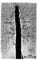
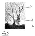
- Fig. 5 is a photograph of the extracted nanotube polymer composite 7 with carbon nanotubes 3 and polymer 5 also indicated.
- Figs. 1 to 5 show the interaction of the polymer with the nanotubes.
- a nanotube 3 is shown having a generally cylindrical wall 6 with an internal cavity 7.
- the polymer 5 initially wraps or coils about the nanotube 3 (see Figs. 1 and 2).
- branches 8 of polymer extend outwardly from the nanotube 3 (see Figs. 3 and 4).
- Branches 8 of polymer on adjacent nanotubes 3 then interengage to form a web which strongly binds the nanotubes together. This web can be seen indicated at 5 on Fig. 5.
- nanotubes are therefore a useful additive for forming anti-static sheets and films as well as for producing organic semiconductor devices with enhanced charge carrier mobility.
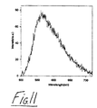
- a light emitting diode 10 in which the active layer comprises a 0.1 mass fraction of nanotube composite 20.
- the diode 10 consists of a 1 ⁇ m thick layer of nanotube polymer composite 20 on top of an indium tin oxide contact 30 on a glass substrate 40.
- the top contact 15 is an evaporated aluminium layer forming an aluminium electrode.
- the diode 10 exhibits a current of 0.1 A for a switch on bias of 14 V.
- the spectrum of light emitted is shown in Fig. 11.
- the diode represents a prototype semiconductor device where the charge carrier mobility and electrical conductivity are enhanced by the presence of nanotubes.
- the same device performance using the pure polymer requires a film thickness of less than 0.1 ⁇ m which leads to severe fabrication problems and much poorer device efficiency.
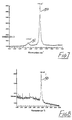
- Figs. 7 and 8 show Raman spectrum of unpurified nanotube soot (Fig. 7) and the purified nanotube polymer composite (Fig. 8).
- Fig. 7 there is a nanotube peak 50 and an amorphous material peak 51.
- Fig. 8 the amorphous material peak has disappeared in the spectrum of the purified composite.
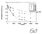
- Fig. 9 is a graph showing reduced degradation of plastic with the incorporation of the nanotube polymer composite. Several graph lines are shown illustrating 0%, 10%, 20% and 25% mass fraction of nanotube content in the polymer.
- nanotubes in conjunction with the polymer has many benefits. We have observed that the polymer and nanotube bind well together. This gives mechanical reinforcement to the polymer.
- the introduction of thermally conductive nanotubes should dramatically reduce the polymers susceptibility to thermal degradation. Thermal degradation is one of the major reasons for the limited lifetime of luminescent polymers. Other notable benefits are a huge increase in conductivity of the order of 10 6 due to the introduction of nanotubes.
- the introduction of nanotubes also reduces aggregation affects and helps to suppress inter-chain non-radiative decay.
- the present invention provides a nanotube polymer composite with technological applications comprising antistatic coatings and packaging as well as semi-conductor devices including light emitting diodes.
- the nanotube polymer composite has electrical conductivity of up to 10 -3 Sm -1 and has application for use in static protection.
- the nanotube polymer composite also has application for use in superconductivity; mechanical reinforcement: domestic, automotive and aerospace; optoelectronic technologies, telecommunications, signal processing (large non-linear optical effects).
- the carbon nanotubes can be purified in a non-destructive method. Good yields of material (in the order of 20%) are provided compared to other methods.
- the method of the present invention is highly reproducible from batch to batch.
- the present invention avoids the use of hazardous explosive or corrosive materials.
- the method provides a useful polymer nanotube composite material with relatively high electrical conduction which can be blended with other plastics or used as is.
- Nanotubes can be used for static protection in a matrix with polymers and oligomers, conjugated and non-conjugated which can also be used in: -
- the nanotubes can induce an increase in conductivity to provide this protection.
- elastic-plastic fibre-reinforced composite materials fibre-reinforced composite materials for strength which can prevent failure seen in other matrix composites since the onset of plastic yielding starts very early in the loading process as compared to the composite's ultimate strength.
- Elastic-plastic behaviour of nanotube-plastic composites consisting of aligned and non-aligned, continuous elastic filaments can be described in terms of the constituent properties, their volume fractions, and mutual constraints between phases indicated by the geometry of the microstructure.
- the nanotube composite prevents degradation of plastics in light, heat and air, and reinforces the plastic for strength and durability.
- the nanotube composite can be used in part for space suit manufacture and fabrication, EMF shielding for the suit. It may also be used to form a radiowave "shield” for applications such as stealth plane, military vehicles and vessels, rockets and space vehicles of all types.
- the composite can be used to provide a protective coating in part or full for vehicles including space vehicles, aeroplanes, ships, tanks, etc.
- the nanotube extracting polymer has a natural fluorescence which is greatly enhanced by combination with nanotubes. This has widespread applications in display technology.
Abstract
Description

Claims (13)
- A process for purifying nanotube soot comprising the steps of:-adding nanotube soot to a solvent which includes an organic nanotube extracting material having a coiling structure to form a solution;mixing the solution to form a nanotube composite suspension and separate solid material;allowing the separate solid material to settle; andremoving the nanotube composite suspension.
- A process as claimed in claim 1 wherein the nanotube extracting material is one or more polymer, oligomer or monomer or combinations thereof.
- A process as claimed in any preceding claim wherein the nanotube extracting material is poly(m-phenylene-co-2,5-dioctoxy-p-phenylenevinylene).
- A process as claimed in any preceding claim wherein the solvent used is an organic solvent.
- A process as claimed in claim 4 wherein the organic solvent is an arene aromatic hydrocarbon.
- A process as claimed in any preceding claim wherein the solution is mixed by sonication.
- A process as claimed in any preceding claim wherein the solution is mixed in a low power ultrasonic bath.
- A process as claimed in claim 7 wherein the solution is mixed in the bath for at least 20 minutes.
- A nanotube composite suspension comprising an organic nanotube extracting material having a coiling structure whenever produced by the process as claimed in any preceding claim.
- A composition which includes nanotubes and an organic material having a coiling structure.
- A composition as claimed in claim 10 wherein the organic material comprises one or more polymer, oligomer or monomer or combinations thereof.
- A composition as claimed in claim 11 wherein the organic material is a polymer.
- A composition as claimed in claim 12 wherein the polymer is poly(m-phenylene-co-2,5-dioctoxy-p-phenylenevinylene).
Applications Claiming Priority (2)
| Application Number | Priority Date | Filing Date | Title |
|---|---|---|---|
| IE980272 | 1998-04-09 | ||
| IE980272 | 1998-04-09 |
Publications (2)
| Publication Number | Publication Date |
|---|---|
| EP0949199A1 EP0949199A1 (en) | 1999-10-13 |
| EP0949199B1 true EP0949199B1 (en) | 2003-05-21 |
Family
ID=11041762
Family Applications (1)
| Application Number | Title | Priority Date | Filing Date |
|---|---|---|---|
| EP99650033A Expired - Lifetime EP0949199B1 (en) | 1998-04-09 | 1999-04-09 | Composition including nanotubes and an organic compound |
Country Status (6)
| Country | Link |
|---|---|
| US (1) | US6576341B1 (en) |
| EP (1) | EP0949199B1 (en) |
| JP (1) | JP4696229B2 (en) |
| AT (1) | ATE240906T1 (en) |
| DE (1) | DE69908016T2 (en) |
| ES (1) | ES2205746T3 (en) |
Cited By (6)
| Publication number | Priority date | Publication date | Assignee | Title |
|---|---|---|---|---|
| US7411019B1 (en) | 2003-08-25 | 2008-08-12 | Eltron Research, Inc. | Polymer composites containing nanotubes |
| US7750071B2 (en) | 2001-03-22 | 2010-07-06 | Clemson University | Halogen containing-polymer nanocomposite compositions, methods, and products employing such compositions |
| CN101485962B (en) * | 2008-11-06 | 2011-05-04 | 青岛大学 | Simple method for dispersing carbon nano-tube |
| US8558105B2 (en) | 2006-05-01 | 2013-10-15 | Wake Forest University | Organic optoelectronic devices and applications thereof |
| US8772629B2 (en) | 2006-05-01 | 2014-07-08 | Wake Forest University | Fiber photovoltaic devices and applications thereof |
| US9105848B2 (en) | 2006-08-07 | 2015-08-11 | Wake Forest University | Composite organic materials and applications thereof |
Families Citing this family (71)
| Publication number | Priority date | Publication date | Assignee | Title |
|---|---|---|---|---|
| KR100404187B1 (en) * | 2000-07-08 | 2003-11-01 | 엘지전자 주식회사 | inductor using carbon nano tube or carbon nano fiber |
| US7008563B2 (en) | 2000-08-24 | 2006-03-07 | William Marsh Rice University | Polymer-wrapped single wall carbon nanotubes |
| JP2002105314A (en) * | 2000-09-29 | 2002-04-10 | Shimadzu Corp | Lubricating composition |
| US20020145791A1 (en) * | 2001-01-23 | 2002-10-10 | Lee Cheng | Optical component having a reduced thermal sensitivity |
| JP3578098B2 (en) | 2001-03-16 | 2004-10-20 | 富士ゼロックス株式会社 | Manufacturing method of electrical connector, electrical connector, and electrical wiring method |
| EP1385481A4 (en) | 2001-03-26 | 2006-06-07 | Eikos Inc | Carbon nanotubes in structures and repair compositions |
| AU2002254367B2 (en) | 2001-03-26 | 2007-12-06 | Eikos, Inc. | Coatings containing carbon nanotubes |
| US6723299B1 (en) | 2001-05-17 | 2004-04-20 | Zyvex Corporation | System and method for manipulating nanotubes |
| CA2450014A1 (en) * | 2001-06-08 | 2002-12-19 | Eikos, Inc. | Nanocomposite dielectrics |
| US6878361B2 (en) | 2001-07-10 | 2005-04-12 | Battelle Memorial Institute | Production of stable aqueous dispersions of carbon nanotubes |
| US6896864B2 (en) | 2001-07-10 | 2005-05-24 | Battelle Memorial Institute | Spatial localization of dispersed single walled carbon nanotubes into useful structures |
| WO2003024798A1 (en) * | 2001-09-18 | 2003-03-27 | Eikos, Inc. | Esd coatings for use with spacecraft |
| JP5061414B2 (en) * | 2001-09-27 | 2012-10-31 | 東レ株式会社 | Thin film transistor element |
| JP2005508067A (en) * | 2001-10-29 | 2005-03-24 | ハイピリオン カタリシス インターナショナル インコーポレイテッド | Polymers containing functionalized carbon nanotubes |
| AU2002357065B2 (en) * | 2001-12-12 | 2008-09-04 | Ashland Inc. | Preparation of stable carbon nanotube dispersions in liquids |
| US20040038251A1 (en) * | 2002-03-04 | 2004-02-26 | Smalley Richard E. | Single-wall carbon nanotubes of precisely defined type and use thereof |
| US7223811B2 (en) | 2002-03-20 | 2007-05-29 | Facultes Universitaires Notre-Dame De La Paix | Nanocomposite: products, process for obtaining them and uses thereof |
| AU2003218335A1 (en) * | 2002-03-20 | 2003-10-08 | The Trustees Of The University Of Pennsylvania | Nanostructure composites |
| EP1398300A1 (en) * | 2002-09-04 | 2004-03-17 | A.S.B.L. Facultes Universitaires Notre-Dame De La Paix | Nanocomposites: Process for obtaining them, products, and uses thereof |
| US20040034177A1 (en) | 2002-05-02 | 2004-02-19 | Jian Chen | Polymer and method for using the polymer for solubilizing nanotubes |
| US6905667B1 (en) * | 2002-05-02 | 2005-06-14 | Zyvex Corporation | Polymer and method for using the polymer for noncovalently functionalizing nanotubes |
| US7029645B2 (en) * | 2002-06-18 | 2006-04-18 | Motorola, Inc. | Method for non-reactive separation of nanomorphic carbon species |
| JP4547852B2 (en) * | 2002-09-04 | 2010-09-22 | 富士ゼロックス株式会社 | Manufacturing method of electrical parts |
| AU2003251307A1 (en) * | 2002-09-10 | 2004-04-30 | The Trustees Of The University Pennsylvania | Carbon nanotubes: high solids dispersions and nematic gels thereof |
| US7108773B2 (en) * | 2002-09-11 | 2006-09-19 | The Board Of Trustees Of The University Of Illinois | Solids supporting mass transfer for fuel cells and other applications and solutions and methods for forming |
| US7844347B2 (en) * | 2002-12-06 | 2010-11-30 | Medtronic, Inc. | Medical devices incorporating carbon nanotube material and methods of fabricating same |
| AU2003300816A1 (en) * | 2002-12-06 | 2004-06-30 | The Penn State Research Foundation | Synthesis of coiled carbon nanotubes by microwave chemical vapor deposition |
| US7244499B2 (en) * | 2003-01-10 | 2007-07-17 | Sanyo Electric Co., Ltd. | Bonded structure including a carbon nanotube |
| US6762073B1 (en) * | 2003-02-24 | 2004-07-13 | Donald P. Cullen | Method of fabricating electronic interconnect devices using direct imaging of dielectric composite material |
| US7285591B2 (en) * | 2003-03-20 | 2007-10-23 | The Trustees Of The University Of Pennsylvania | Polymer-nanotube composites, fibers, and processes |
| US20040211942A1 (en) * | 2003-04-28 | 2004-10-28 | Clark Darren Cameron | Electrically conductive compositions and method of manufacture thereof |
| US20040232389A1 (en) * | 2003-05-22 | 2004-11-25 | Elkovitch Mark D. | Electrically conductive compositions and method of manufacture thereof |
| GB2421506B (en) | 2003-05-22 | 2008-07-09 | Zyvex Corp | Nanocomposites and methods thereto |
| US7956108B2 (en) | 2003-05-30 | 2011-06-07 | The Provost, Fellows And Scholars Of The College Of The Holy And Undivided Trinity Of Queen Elizabeth, Near Dublin | Product |
| US20040262581A1 (en) * | 2003-06-27 | 2004-12-30 | Rodrigues David E. | Electrically conductive compositions and method of manufacture thereof |
| KR20060060682A (en) * | 2003-08-08 | 2006-06-05 | 제너럴 일렉트릭 캄파니 | Electrically conductive compositions comprising carbon nanotubes and method of manufacture thereof |
| US7354988B2 (en) * | 2003-08-12 | 2008-04-08 | General Electric Company | Electrically conductive compositions and method of manufacture thereof |
| US7026432B2 (en) * | 2003-08-12 | 2006-04-11 | General Electric Company | Electrically conductive compositions and method of manufacture thereof |
| FR2859988A1 (en) * | 2003-09-18 | 2005-03-25 | Nanoledge | Dispersions of carbon nanotubes in organic solvents, useful in production of composites with e.g. electroconductive properties, prepared using stabilizing combination of surfactant and polymer |
| US7309727B2 (en) * | 2003-09-29 | 2007-12-18 | General Electric Company | Conductive thermoplastic compositions, methods of manufacture and articles derived from such compositions |
| US20050070658A1 (en) * | 2003-09-30 | 2005-03-31 | Soumyadeb Ghosh | Electrically conductive compositions, methods of manufacture thereof and articles derived from such compositions |
| US7959783B2 (en) | 2003-09-30 | 2011-06-14 | The Boeing Company | Electrochemical deposition process for composite structures |
| JP4868490B2 (en) * | 2004-01-06 | 2012-02-01 | 国立大学法人京都大学 | Carbon nanotube purification method |
| US20050238565A1 (en) * | 2004-04-27 | 2005-10-27 | Steven Sullivan | Systems and methods of manufacturing nanotube structures |
| US7358291B2 (en) * | 2004-06-24 | 2008-04-15 | Arrowhead Center, Inc. | Nanocomposite for enhanced rectification |
| US20060293434A1 (en) * | 2004-07-07 | 2006-12-28 | The Trustees Of The University Of Pennsylvania | Single wall nanotube composites |
| US7296576B2 (en) | 2004-08-18 | 2007-11-20 | Zyvex Performance Materials, Llc | Polymers for enhanced solubility of nanomaterials, compositions and methods therefor |
| US7462656B2 (en) * | 2005-02-15 | 2008-12-09 | Sabic Innovative Plastics Ip B.V. | Electrically conductive compositions and method of manufacture thereof |
| CA2575479C (en) * | 2005-03-25 | 2012-05-22 | Institut National De La Recherche Scientifique | Methods and apparatuses for purifying carbon filamentary structures |
| JP4742650B2 (en) * | 2005-04-08 | 2011-08-10 | 東レ株式会社 | Carbon nanotube composition, biosensor, and production method thereof |
| JP2007118112A (en) * | 2005-10-26 | 2007-05-17 | National Institute For Materials Science | Method for preparing nano-tree/nano-particle composite structure, and nano-tree/nano-particle composite structure |
| FR2895393B1 (en) * | 2005-12-23 | 2008-03-07 | Arkema Sa | PROCESS FOR THE SYNTHESIS OF CARBON NANOTUBES |
| JP4670100B2 (en) * | 2006-03-01 | 2011-04-13 | 独立行政法人物質・材料研究機構 | Method for purifying boron nitride nanotubes |
| US20080149178A1 (en) * | 2006-06-27 | 2008-06-26 | Marisol Reyes-Reyes | Composite organic materials and applications thereof |
| US20100247419A1 (en) * | 2006-11-01 | 2010-09-30 | Nguyen Khe C | Solid phase synthesized carbon nano fiber and tube |
| EP2151415A4 (en) | 2007-05-09 | 2014-01-22 | Univ Kyushu Nat Univ Corp | Carbon nanotube solubilizer |
| US20100307580A1 (en) * | 2007-11-01 | 2010-12-09 | David Loren Carroll | Lateral Organic Optoelectronic Devices And Applications Thereof |
| FR2924133B1 (en) * | 2007-11-26 | 2012-12-14 | Porcher Ind | LONGITUDINAL REINFORCING ELEMENT BASED ON MINERAL OR ORGANIC FIBERS AND METHOD OF OBTAINING THE SAME |
| WO2009128449A1 (en) * | 2008-04-15 | 2009-10-22 | 国立大学法人九州大学 | Carbon nanotube solubilizer consisting of aroylbiphenyl-type hyperbranch polymer |
| JP2009274900A (en) * | 2008-05-14 | 2009-11-26 | Tatsuhiro Takahashi | Carbon nanotube having low molecular weight polyaniline grafted thereto and its dispersion liquid |
| JP2009179808A (en) * | 2009-05-18 | 2009-08-13 | Bridgestone Corp | Side-reinforced run flat tire |
| JP5716670B2 (en) | 2009-11-25 | 2015-05-13 | 日産化学工業株式会社 | Carbon nanotube dispersant |
| EP2693444B1 (en) | 2011-03-28 | 2019-03-13 | FUJIFILM Corporation | An electrically conductive composition, an electrically conductive film using the composition and a method of producing the same |
| JP5939250B2 (en) | 2011-05-25 | 2016-06-22 | 日産化学工業株式会社 | Conductive composition and conductive composite |
| KR101889094B1 (en) | 2011-05-25 | 2018-08-16 | 닛산 가가쿠 가부시키가이샤 | Highly branched polymer and dispersant for carbon nanotubes |
| US9156698B2 (en) | 2012-02-29 | 2015-10-13 | Yazaki Corporation | Method of purifying carbon nanotubes and applications thereof |
| WO2015016316A1 (en) | 2013-07-31 | 2015-02-05 | 日産化学工業株式会社 | Carbon material dispersed film formation composition |
| WO2015029949A1 (en) | 2013-08-27 | 2015-03-05 | 日産化学工業株式会社 | Agent for dispersing electrically conductive carbon material, and dispersion of electrically conductive carbon material |
| US10578094B2 (en) | 2016-05-04 | 2020-03-03 | Curium Us Llc | Pump for operation in radioactive environment |
| CN110902670B (en) | 2018-09-14 | 2021-07-20 | 中国科学院苏州纳米技术与纳米仿生研究所 | Carbon nanotube oriented film, preparation method and application thereof |
| WO2021172306A1 (en) | 2020-02-27 | 2021-09-02 | 日産化学株式会社 | Carbon nanotube dispersion |
Family Cites Families (5)
| Publication number | Priority date | Publication date | Assignee | Title |
|---|---|---|---|---|
| US5281653A (en) * | 1991-11-25 | 1994-01-25 | Exxon Research And Engineering Company | Fullerene-polymer compositions |
| JPH0822733B2 (en) | 1993-08-04 | 1996-03-06 | 工業技術院長 | Separation and purification method of carbon nanotube |
| JP2654918B2 (en) * | 1994-01-09 | 1997-09-17 | 科学技術振興事業団 | Fullerene purification method |
| CA2185443C (en) * | 1994-03-16 | 2007-10-23 | Jerry L. Atwood | Method for the separation and purification of fullerenes |
| US5866434A (en) * | 1994-12-08 | 1999-02-02 | Meso Scale Technology | Graphitic nanotubes in luminescence assays |
-
1999
- 1999-04-09 AT AT99650033T patent/ATE240906T1/en active
- 1999-04-09 ES ES99650033T patent/ES2205746T3/en not_active Expired - Lifetime
- 1999-04-09 US US09/288,671 patent/US6576341B1/en not_active Expired - Lifetime
- 1999-04-09 DE DE69908016T patent/DE69908016T2/en not_active Expired - Lifetime
- 1999-04-09 EP EP99650033A patent/EP0949199B1/en not_active Expired - Lifetime
- 1999-04-09 JP JP10335499A patent/JP4696229B2/en not_active Expired - Fee Related
Cited By (6)
| Publication number | Priority date | Publication date | Assignee | Title |
|---|---|---|---|---|
| US7750071B2 (en) | 2001-03-22 | 2010-07-06 | Clemson University | Halogen containing-polymer nanocomposite compositions, methods, and products employing such compositions |
| US7411019B1 (en) | 2003-08-25 | 2008-08-12 | Eltron Research, Inc. | Polymer composites containing nanotubes |
| US8558105B2 (en) | 2006-05-01 | 2013-10-15 | Wake Forest University | Organic optoelectronic devices and applications thereof |
| US8772629B2 (en) | 2006-05-01 | 2014-07-08 | Wake Forest University | Fiber photovoltaic devices and applications thereof |
| US9105848B2 (en) | 2006-08-07 | 2015-08-11 | Wake Forest University | Composite organic materials and applications thereof |
| CN101485962B (en) * | 2008-11-06 | 2011-05-04 | 青岛大学 | Simple method for dispersing carbon nano-tube |
Also Published As
| Publication number | Publication date |
|---|---|
| DE69908016D1 (en) | 2003-06-26 |
| ES2205746T3 (en) | 2004-05-01 |
| DE69908016T2 (en) | 2004-08-19 |
| JP4696229B2 (en) | 2011-06-08 |
| JP2000044216A (en) | 2000-02-15 |
| ATE240906T1 (en) | 2003-06-15 |
| US6576341B1 (en) | 2003-06-10 |
| EP0949199A1 (en) | 1999-10-13 |
Similar Documents
| Publication | Publication Date | Title |
|---|---|---|
| EP0949199B1 (en) | Composition including nanotubes and an organic compound | |
| RU2389739C2 (en) | Polymer compositions containing nanotubes | |
| US6908572B1 (en) | Mixing and dispersion of nanotubes by gas or vapor expansion | |
| Li et al. | Polydopamine coating layer on graphene for suppressing loss tangent and enhancing dielectric constant of poly (vinylidene fluoride)/graphene composites | |
| Tanaka et al. | Generic PD resistance characteristics of polymer nanocomposites | |
| KR100724235B1 (en) | Thin film producing method, base material having thin film, electron emission material, method of producing electron emission material, and electron emitter | |
| EP2268102A1 (en) | Planar heating element obtained using dispersion of fine carbon fibers in water and process for producing the planar heating element | |
| US7956108B2 (en) | Product | |
| KR101307303B1 (en) | Transparent electroconductive thin film and process for producing the transparent electroconductive thin film | |
| WO2017065340A1 (en) | Method for manufacturing two-dimensional hybrid composite | |
| WO2009032062A2 (en) | Conductive composite compositions with fillers | |
| US20120095143A1 (en) | Dispersion and retrieval of de-bundled nanotubes | |
| US20100038595A1 (en) | System and methods of dispersion of nanostructures in composite materials | |
| US20090311436A1 (en) | Conductive composite materials with graphite coated particles | |
| WO2009051561A1 (en) | Composite films comprising carbon nanotubes and polymer | |
| Kareem et al. | Electrical and thermal characteristics of MWCNTs modified carbon fiber/epoxy composite films | |
| CN108137837B (en) | Method for producing a composite conductive material and composite material obtained with this method | |
| Liu et al. | High dielectric constant epoxy nanocomposites containing ZnO quantum dots decorated carbon nanotube | |
| JP2002519830A (en) | Brightly colored conductive coated particles and compositions made therefrom | |
| IE990298A1 (en) | A composition | |
| CN113845119A (en) | Silane-treated forsterite fine particles, organic solvent dispersion thereof, and method for producing same | |
| JP6002077B2 (en) | Transparent conductive film and method for producing the same | |
| Shen et al. | Sub‐micron calcium carbonate isolated carbon nanotubes/polyethylene composites with controllable electrical conductivity | |
| WO2016175552A1 (en) | Method for preparing conductive resin composite, and conductive resin composite prepared thereby | |
| EP2882801B1 (en) | Conductive polymeric materials, preparation and use thereof |
Legal Events
| Date | Code | Title | Description |
|---|---|---|---|
| PUAI | Public reference made under article 153(3) epc to a published international application that has entered the european phase |
Free format text: ORIGINAL CODE: 0009012 |
|
| AK | Designated contracting states |
Kind code of ref document: A1 Designated state(s): AT BE CH CY DE DK ES FI FR GB GR IE IT LI LU MC NL PT SE |
|
| AX | Request for extension of the european patent |
Free format text: AL;LT;LV;MK;RO;SI |
|
| 17P | Request for examination filed |
Effective date: 20000316 |
|
| AKX | Designation fees paid |
Free format text: AT BE CH CY DE DK ES FI FR GB GR IE IT LI LU MC NL PT SE |
|
| 17Q | First examination report despatched |
Effective date: 20010713 |
|
| GRAH | Despatch of communication of intention to grant a patent |
Free format text: ORIGINAL CODE: EPIDOS IGRA |
|
| GRAH | Despatch of communication of intention to grant a patent |
Free format text: ORIGINAL CODE: EPIDOS IGRA |
|
| GRAA | (expected) grant |
Free format text: ORIGINAL CODE: 0009210 |
|
| AK | Designated contracting states |
Designated state(s): AT BE CH CY DE DK ES FI FR GB GR IE IT LI LU MC NL PT SE |
|
| PG25 | Lapsed in a contracting state [announced via postgrant information from national office to epo] |
Ref country code: FI Free format text: LAPSE BECAUSE OF FAILURE TO SUBMIT A TRANSLATION OF THE DESCRIPTION OR TO PAY THE FEE WITHIN THE PRESCRIBED TIME-LIMIT Effective date: 20030521 |
|
| REG | Reference to a national code |
Ref country code: GB Ref legal event code: FG4D |
|
| REG | Reference to a national code |
Ref country code: CH Ref legal event code: EP |
|
| REG | Reference to a national code |
Ref country code: IE Ref legal event code: FG4D |
|
| REF | Corresponds to: |
Ref document number: 69908016 Country of ref document: DE Date of ref document: 20030626 Kind code of ref document: P |
|
| PG25 | Lapsed in a contracting state [announced via postgrant information from national office to epo] |
Ref country code: SE Free format text: LAPSE BECAUSE OF FAILURE TO SUBMIT A TRANSLATION OF THE DESCRIPTION OR TO PAY THE FEE WITHIN THE PRESCRIBED TIME-LIMIT Effective date: 20030821 Ref country code: PT Free format text: LAPSE BECAUSE OF FAILURE TO SUBMIT A TRANSLATION OF THE DESCRIPTION OR TO PAY THE FEE WITHIN THE PRESCRIBED TIME-LIMIT Effective date: 20030821 Ref country code: GR Free format text: LAPSE BECAUSE OF FAILURE TO SUBMIT A TRANSLATION OF THE DESCRIPTION OR TO PAY THE FEE WITHIN THE PRESCRIBED TIME-LIMIT Effective date: 20030821 Ref country code: DK Free format text: LAPSE BECAUSE OF FAILURE TO SUBMIT A TRANSLATION OF THE DESCRIPTION OR TO PAY THE FEE WITHIN THE PRESCRIBED TIME-LIMIT Effective date: 20030821 |
|
| PLBE | No opposition filed within time limit |
Free format text: ORIGINAL CODE: 0009261 |
|
| STAA | Information on the status of an ep patent application or granted ep patent |
Free format text: STATUS: NO OPPOSITION FILED WITHIN TIME LIMIT |
|
| ET | Fr: translation filed | ||
| PG25 | Lapsed in a contracting state [announced via postgrant information from national office to epo] |
Ref country code: LU Free format text: LAPSE BECAUSE OF NON-PAYMENT OF DUE FEES Effective date: 20040409 |
|
| PG25 | Lapsed in a contracting state [announced via postgrant information from national office to epo] |
Ref country code: MC Free format text: LAPSE BECAUSE OF NON-PAYMENT OF DUE FEES Effective date: 20040430 |
|
| REG | Reference to a national code |
Ref country code: ES Ref legal event code: FG2A Ref document number: 2205746 Country of ref document: ES Kind code of ref document: T3 |
|
| 26N | No opposition filed |
Effective date: 20040224 |
|
| PGFP | Annual fee paid to national office [announced via postgrant information from national office to epo] |
Ref country code: CY Payment date: 20070419 Year of fee payment: 9 |
|
| PG25 | Lapsed in a contracting state [announced via postgrant information from national office to epo] |
Ref country code: CY Free format text: LAPSE BECAUSE OF NON-PAYMENT OF DUE FEES Effective date: 20080409 |
|
| PGFP | Annual fee paid to national office [announced via postgrant information from national office to epo] |
Ref country code: DE Payment date: 20120628 Year of fee payment: 14 Ref country code: IE Payment date: 20120427 Year of fee payment: 14 Ref country code: NL Payment date: 20120508 Year of fee payment: 14 Ref country code: CH Payment date: 20120427 Year of fee payment: 14 |
|
| PGFP | Annual fee paid to national office [announced via postgrant information from national office to epo] |
Ref country code: FR Payment date: 20120531 Year of fee payment: 14 Ref country code: GB Payment date: 20120427 Year of fee payment: 14 |
|
| PGFP | Annual fee paid to national office [announced via postgrant information from national office to epo] |
Ref country code: IT Payment date: 20120430 Year of fee payment: 14 |
|
| PGFP | Annual fee paid to national office [announced via postgrant information from national office to epo] |
Ref country code: BE Payment date: 20120618 Year of fee payment: 14 |
|
| PGFP | Annual fee paid to national office [announced via postgrant information from national office to epo] |
Ref country code: ES Payment date: 20120516 Year of fee payment: 14 |
|
| PGFP | Annual fee paid to national office [announced via postgrant information from national office to epo] |
Ref country code: AT Payment date: 20120502 Year of fee payment: 14 |
|
| BERE | Be: lapsed |
Owner name: *HORCOM LTD Effective date: 20130430 Owner name: *ENTERPRISE IRELAND (TRADING AS MATERIALS IRELAND) Effective date: 20130430 Owner name: THE *PROVOST FELLOWS AND SCHOLARS OF THE COLLEGE O Effective date: 20130430 |
|
| REG | Reference to a national code |
Ref country code: NL Ref legal event code: V1 Effective date: 20131101 |
|
| REG | Reference to a national code |
Ref country code: CH Ref legal event code: PL |
|
| REG | Reference to a national code |
Ref country code: AT Ref legal event code: MM01 Ref document number: 240906 Country of ref document: AT Kind code of ref document: T Effective date: 20130430 |
|
| GBPC | Gb: european patent ceased through non-payment of renewal fee |
Effective date: 20130409 |
|
| REG | Reference to a national code |
Ref country code: IE Ref legal event code: MM4A |
|
| PG25 | Lapsed in a contracting state [announced via postgrant information from national office to epo] |
Ref country code: CH Free format text: LAPSE BECAUSE OF NON-PAYMENT OF DUE FEES Effective date: 20130430 Ref country code: LI Free format text: LAPSE BECAUSE OF NON-PAYMENT OF DUE FEES Effective date: 20130430 Ref country code: GB Free format text: LAPSE BECAUSE OF NON-PAYMENT OF DUE FEES Effective date: 20130409 Ref country code: AT Free format text: LAPSE BECAUSE OF NON-PAYMENT OF DUE FEES Effective date: 20130430 Ref country code: BE Free format text: LAPSE BECAUSE OF NON-PAYMENT OF DUE FEES Effective date: 20130430 Ref country code: DE Free format text: LAPSE BECAUSE OF NON-PAYMENT OF DUE FEES Effective date: 20131101 |
|
| REG | Reference to a national code |
Ref country code: FR Ref legal event code: ST Effective date: 20131231 |
|
| REG | Reference to a national code |
Ref country code: DE Ref legal event code: R119 Ref document number: 69908016 Country of ref document: DE Effective date: 20131101 |
|
| PG25 | Lapsed in a contracting state [announced via postgrant information from national office to epo] |
Ref country code: FR Free format text: LAPSE BECAUSE OF NON-PAYMENT OF DUE FEES Effective date: 20130430 Ref country code: NL Free format text: LAPSE BECAUSE OF NON-PAYMENT OF DUE FEES Effective date: 20131101 Ref country code: IT Free format text: LAPSE BECAUSE OF NON-PAYMENT OF DUE FEES Effective date: 20130409 |
|
| PG25 | Lapsed in a contracting state [announced via postgrant information from national office to epo] |
Ref country code: IE Free format text: LAPSE BECAUSE OF NON-PAYMENT OF DUE FEES Effective date: 20130409 |
|
| REG | Reference to a national code |
Ref country code: ES Ref legal event code: FD2A Effective date: 20140606 |
|
| PG25 | Lapsed in a contracting state [announced via postgrant information from national office to epo] |
Ref country code: ES Free format text: LAPSE BECAUSE OF NON-PAYMENT OF DUE FEES Effective date: 20130410 |