EP0949993B1 - Apparatus for fabricating a three-dimensional object and method of assembling an apparatus for fabricating a three-dimensional object - Google Patents
Apparatus for fabricating a three-dimensional object and method of assembling an apparatus for fabricating a three-dimensional object Download PDFInfo
- Publication number
- EP0949993B1 EP0949993B1 EP97953459A EP97953459A EP0949993B1 EP 0949993 B1 EP0949993 B1 EP 0949993B1 EP 97953459 A EP97953459 A EP 97953459A EP 97953459 A EP97953459 A EP 97953459A EP 0949993 B1 EP0949993 B1 EP 0949993B1
- Authority
- EP
- European Patent Office
- Prior art keywords
- binder
- build
- build material
- jets
- overflow cavity
- Prior art date
- Legal status (The legal status is an assumption and is not a legal conclusion. Google has not performed a legal analysis and makes no representation as to the accuracy of the status listed.)
- Expired - Lifetime
Links
Images


Classifications
-
- B—PERFORMING OPERATIONS; TRANSPORTING
- B29—WORKING OF PLASTICS; WORKING OF SUBSTANCES IN A PLASTIC STATE IN GENERAL
- B29C—SHAPING OR JOINING OF PLASTICS; SHAPING OF MATERIAL IN A PLASTIC STATE, NOT OTHERWISE PROVIDED FOR; AFTER-TREATMENT OF THE SHAPED PRODUCTS, e.g. REPAIRING
- B29C41/00—Shaping by coating a mould, core or other substrate, i.e. by depositing material and stripping-off the shaped article; Apparatus therefor
- B29C41/34—Component parts, details or accessories; Auxiliary operations
- B29C41/36—Feeding the material on to the mould, core or other substrate
-
- B—PERFORMING OPERATIONS; TRANSPORTING
- B29—WORKING OF PLASTICS; WORKING OF SUBSTANCES IN A PLASTIC STATE IN GENERAL
- B29C—SHAPING OR JOINING OF PLASTICS; SHAPING OF MATERIAL IN A PLASTIC STATE, NOT OTHERWISE PROVIDED FOR; AFTER-TREATMENT OF THE SHAPED PRODUCTS, e.g. REPAIRING
- B29C41/00—Shaping by coating a mould, core or other substrate, i.e. by depositing material and stripping-off the shaped article; Apparatus therefor
- B29C41/02—Shaping by coating a mould, core or other substrate, i.e. by depositing material and stripping-off the shaped article; Apparatus therefor for making articles of definite length, i.e. discrete articles
- B29C41/12—Spreading-out the material on a substrate, e.g. on the surface of a liquid
-
- B—PERFORMING OPERATIONS; TRANSPORTING
- B29—WORKING OF PLASTICS; WORKING OF SUBSTANCES IN A PLASTIC STATE IN GENERAL
- B29C—SHAPING OR JOINING OF PLASTICS; SHAPING OF MATERIAL IN A PLASTIC STATE, NOT OTHERWISE PROVIDED FOR; AFTER-TREATMENT OF THE SHAPED PRODUCTS, e.g. REPAIRING
- B29C64/00—Additive manufacturing, i.e. manufacturing of three-dimensional [3D] objects by additive deposition, additive agglomeration or additive layering, e.g. by 3D printing, stereolithography or selective laser sintering
- B29C64/10—Processes of additive manufacturing
- B29C64/165—Processes of additive manufacturing using a combination of solid and fluid materials, e.g. a powder selectively bound by a liquid binder, catalyst, inhibitor or energy absorber
-
- B—PERFORMING OPERATIONS; TRANSPORTING
- B33—ADDITIVE MANUFACTURING TECHNOLOGY
- B33Y—ADDITIVE MANUFACTURING, i.e. MANUFACTURING OF THREE-DIMENSIONAL [3-D] OBJECTS BY ADDITIVE DEPOSITION, ADDITIVE AGGLOMERATION OR ADDITIVE LAYERING, e.g. BY 3-D PRINTING, STEREOLITHOGRAPHY OR SELECTIVE LASER SINTERING
- B33Y30/00—Apparatus for additive manufacturing; Details thereof or accessories therefor
-
- B—PERFORMING OPERATIONS; TRANSPORTING
- B33—ADDITIVE MANUFACTURING TECHNOLOGY
- B33Y—ADDITIVE MANUFACTURING, i.e. MANUFACTURING OF THREE-DIMENSIONAL [3-D] OBJECTS BY ADDITIVE DEPOSITION, ADDITIVE AGGLOMERATION OR ADDITIVE LAYERING, e.g. BY 3-D PRINTING, STEREOLITHOGRAPHY OR SELECTIVE LASER SINTERING
- B33Y40/00—Auxiliary operations or equipment, e.g. for material handling
- B33Y40/20—Post-treatment, e.g. curing, coating or polishing
-
- B—PERFORMING OPERATIONS; TRANSPORTING
- B41—PRINTING; LINING MACHINES; TYPEWRITERS; STAMPS
- B41J—TYPEWRITERS; SELECTIVE PRINTING MECHANISMS, i.e. MECHANISMS PRINTING OTHERWISE THAN FROM A FORME; CORRECTION OF TYPOGRAPHICAL ERRORS
- B41J2/00—Typewriters or selective printing mechanisms characterised by the printing or marking process for which they are designed
- B41J2/005—Typewriters or selective printing mechanisms characterised by the printing or marking process for which they are designed characterised by bringing liquid or particles selectively into contact with a printing material
- B41J2/01—Ink jet
- B41J2/135—Nozzles
- B41J2/145—Arrangement thereof
- B41J2/155—Arrangement thereof for line printing
-
- B—PERFORMING OPERATIONS; TRANSPORTING
- B41—PRINTING; LINING MACHINES; TYPEWRITERS; STAMPS
- B41J—TYPEWRITERS; SELECTIVE PRINTING MECHANISMS, i.e. MECHANISMS PRINTING OTHERWISE THAN FROM A FORME; CORRECTION OF TYPOGRAPHICAL ERRORS
- B41J2/00—Typewriters or selective printing mechanisms characterised by the printing or marking process for which they are designed
- B41J2/005—Typewriters or selective printing mechanisms characterised by the printing or marking process for which they are designed characterised by bringing liquid or particles selectively into contact with a printing material
- B41J2/01—Ink jet
- B41J2/135—Nozzles
- B41J2/165—Preventing or detecting of nozzle clogging, e.g. cleaning, capping or moistening for nozzles
- B41J2/16517—Cleaning of print head nozzles
- B41J2/16552—Cleaning of print head nozzles using cleaning fluids
-
- B—PERFORMING OPERATIONS; TRANSPORTING
- B41—PRINTING; LINING MACHINES; TYPEWRITERS; STAMPS
- B41J—TYPEWRITERS; SELECTIVE PRINTING MECHANISMS, i.e. MECHANISMS PRINTING OTHERWISE THAN FROM A FORME; CORRECTION OF TYPOGRAPHICAL ERRORS
- B41J2/00—Typewriters or selective printing mechanisms characterised by the printing or marking process for which they are designed
- B41J2/005—Typewriters or selective printing mechanisms characterised by the printing or marking process for which they are designed characterised by bringing liquid or particles selectively into contact with a printing material
- B41J2/01—Ink jet
- B41J2/17—Ink jet characterised by ink handling
- B41J2/175—Ink supply systems ; Circuit parts therefor
- B41J2/17503—Ink cartridges
- B41J2/17513—Inner structure
-
- B—PERFORMING OPERATIONS; TRANSPORTING
- B41—PRINTING; LINING MACHINES; TYPEWRITERS; STAMPS
- B41J—TYPEWRITERS; SELECTIVE PRINTING MECHANISMS, i.e. MECHANISMS PRINTING OTHERWISE THAN FROM A FORME; CORRECTION OF TYPOGRAPHICAL ERRORS
- B41J2/00—Typewriters or selective printing mechanisms characterised by the printing or marking process for which they are designed
- B41J2/005—Typewriters or selective printing mechanisms characterised by the printing or marking process for which they are designed characterised by bringing liquid or particles selectively into contact with a printing material
- B41J2/01—Ink jet
- B41J2/17—Ink jet characterised by ink handling
- B41J2/175—Ink supply systems ; Circuit parts therefor
- B41J2/17503—Ink cartridges
- B41J2/17556—Means for regulating the pressure in the cartridge
-
- B—PERFORMING OPERATIONS; TRANSPORTING
- B41—PRINTING; LINING MACHINES; TYPEWRITERS; STAMPS
- B41J—TYPEWRITERS; SELECTIVE PRINTING MECHANISMS, i.e. MECHANISMS PRINTING OTHERWISE THAN FROM A FORME; CORRECTION OF TYPOGRAPHICAL ERRORS
- B41J2/00—Typewriters or selective printing mechanisms characterised by the printing or marking process for which they are designed
- B41J2/005—Typewriters or selective printing mechanisms characterised by the printing or marking process for which they are designed characterised by bringing liquid or particles selectively into contact with a printing material
- B41J2/01—Ink jet
- B41J2/17—Ink jet characterised by ink handling
- B41J2/175—Ink supply systems ; Circuit parts therefor
- B41J2/17596—Ink pumps, ink valves
-
- B—PERFORMING OPERATIONS; TRANSPORTING
- B22—CASTING; POWDER METALLURGY
- B22F—WORKING METALLIC POWDER; MANUFACTURE OF ARTICLES FROM METALLIC POWDER; MAKING METALLIC POWDER; APPARATUS OR DEVICES SPECIALLY ADAPTED FOR METALLIC POWDER
- B22F10/00—Additive manufacturing of workpieces or articles from metallic powder
- B22F10/10—Formation of a green body
- B22F10/14—Formation of a green body by jetting of binder onto a bed of metal powder
-
- B—PERFORMING OPERATIONS; TRANSPORTING
- B22—CASTING; POWDER METALLURGY
- B22F—WORKING METALLIC POWDER; MANUFACTURE OF ARTICLES FROM METALLIC POWDER; MAKING METALLIC POWDER; APPARATUS OR DEVICES SPECIALLY ADAPTED FOR METALLIC POWDER
- B22F10/00—Additive manufacturing of workpieces or articles from metallic powder
- B22F10/70—Recycling
- B22F10/73—Recycling of powder
-
- B—PERFORMING OPERATIONS; TRANSPORTING
- B22—CASTING; POWDER METALLURGY
- B22F—WORKING METALLIC POWDER; MANUFACTURE OF ARTICLES FROM METALLIC POWDER; MAKING METALLIC POWDER; APPARATUS OR DEVICES SPECIALLY ADAPTED FOR METALLIC POWDER
- B22F12/00—Apparatus or devices specially adapted for additive manufacturing; Auxiliary means for additive manufacturing; Combinations of additive manufacturing apparatus or devices with other processing apparatus or devices
- B22F12/30—Platforms or substrates
- B22F12/33—Platforms or substrates translatory in the deposition plane
-
- B—PERFORMING OPERATIONS; TRANSPORTING
- B22—CASTING; POWDER METALLURGY
- B22F—WORKING METALLIC POWDER; MANUFACTURE OF ARTICLES FROM METALLIC POWDER; MAKING METALLIC POWDER; APPARATUS OR DEVICES SPECIALLY ADAPTED FOR METALLIC POWDER
- B22F12/00—Apparatus or devices specially adapted for additive manufacturing; Auxiliary means for additive manufacturing; Combinations of additive manufacturing apparatus or devices with other processing apparatus or devices
- B22F12/50—Means for feeding of material, e.g. heads
- B22F12/57—Metering means
-
- B—PERFORMING OPERATIONS; TRANSPORTING
- B22—CASTING; POWDER METALLURGY
- B22F—WORKING METALLIC POWDER; MANUFACTURE OF ARTICLES FROM METALLIC POWDER; MAKING METALLIC POWDER; APPARATUS OR DEVICES SPECIALLY ADAPTED FOR METALLIC POWDER
- B22F12/00—Apparatus or devices specially adapted for additive manufacturing; Auxiliary means for additive manufacturing; Combinations of additive manufacturing apparatus or devices with other processing apparatus or devices
- B22F12/60—Planarisation devices; Compression devices
-
- B—PERFORMING OPERATIONS; TRANSPORTING
- B29—WORKING OF PLASTICS; WORKING OF SUBSTANCES IN A PLASTIC STATE IN GENERAL
- B29K—INDEXING SCHEME ASSOCIATED WITH SUBCLASSES B29B, B29C OR B29D, RELATING TO MOULDING MATERIALS OR TO MATERIALS FOR MOULDS, REINFORCEMENTS, FILLERS OR PREFORMED PARTS, e.g. INSERTS
- B29K2995/00—Properties of moulding materials, reinforcements, fillers, preformed parts or moulds
- B29K2995/0018—Properties of moulding materials, reinforcements, fillers, preformed parts or moulds having particular optical properties, e.g. fluorescent or phosphorescent
- B29K2995/002—Coloured
- B29K2995/0021—Multi-coloured
-
- B—PERFORMING OPERATIONS; TRANSPORTING
- B33—ADDITIVE MANUFACTURING TECHNOLOGY
- B33Y—ADDITIVE MANUFACTURING, i.e. MANUFACTURING OF THREE-DIMENSIONAL [3-D] OBJECTS BY ADDITIVE DEPOSITION, ADDITIVE AGGLOMERATION OR ADDITIVE LAYERING, e.g. BY 3-D PRINTING, STEREOLITHOGRAPHY OR SELECTIVE LASER SINTERING
- B33Y10/00—Processes of additive manufacturing
-
- B—PERFORMING OPERATIONS; TRANSPORTING
- B41—PRINTING; LINING MACHINES; TYPEWRITERS; STAMPS
- B41J—TYPEWRITERS; SELECTIVE PRINTING MECHANISMS, i.e. MECHANISMS PRINTING OTHERWISE THAN FROM A FORME; CORRECTION OF TYPOGRAPHICAL ERRORS
- B41J2/00—Typewriters or selective printing mechanisms characterised by the printing or marking process for which they are designed
- B41J2/005—Typewriters or selective printing mechanisms characterised by the printing or marking process for which they are designed characterised by bringing liquid or particles selectively into contact with a printing material
- B41J2/01—Ink jet
- B41J2/135—Nozzles
- B41J2/165—Preventing or detecting of nozzle clogging, e.g. cleaning, capping or moistening for nozzles
- B41J2/16517—Cleaning of print head nozzles
- B41J2/16535—Cleaning of print head nozzles using wiping constructions
- B41J2/16541—Means to remove deposits from wipers or scrapers
-
- B—PERFORMING OPERATIONS; TRANSPORTING
- B41—PRINTING; LINING MACHINES; TYPEWRITERS; STAMPS
- B41J—TYPEWRITERS; SELECTIVE PRINTING MECHANISMS, i.e. MECHANISMS PRINTING OTHERWISE THAN FROM A FORME; CORRECTION OF TYPOGRAPHICAL ERRORS
- B41J2/00—Typewriters or selective printing mechanisms characterised by the printing or marking process for which they are designed
- B41J2/005—Typewriters or selective printing mechanisms characterised by the printing or marking process for which they are designed characterised by bringing liquid or particles selectively into contact with a printing material
- B41J2/01—Ink jet
- B41J2/135—Nozzles
- B41J2/14—Structure thereof only for on-demand ink jet heads
- B41J2002/14475—Structure thereof only for on-demand ink jet heads characterised by nozzle shapes or number of orifices per chamber
-
- B—PERFORMING OPERATIONS; TRANSPORTING
- B41—PRINTING; LINING MACHINES; TYPEWRITERS; STAMPS
- B41J—TYPEWRITERS; SELECTIVE PRINTING MECHANISMS, i.e. MECHANISMS PRINTING OTHERWISE THAN FROM A FORME; CORRECTION OF TYPOGRAPHICAL ERRORS
- B41J2202/00—Embodiments of or processes related to ink-jet or thermal heads
- B41J2202/01—Embodiments of or processes related to ink-jet heads
- B41J2202/20—Modules
-
- Y—GENERAL TAGGING OF NEW TECHNOLOGICAL DEVELOPMENTS; GENERAL TAGGING OF CROSS-SECTIONAL TECHNOLOGIES SPANNING OVER SEVERAL SECTIONS OF THE IPC; TECHNICAL SUBJECTS COVERED BY FORMER USPC CROSS-REFERENCE ART COLLECTIONS [XRACs] AND DIGESTS
- Y02—TECHNOLOGIES OR APPLICATIONS FOR MITIGATION OR ADAPTATION AGAINST CLIMATE CHANGE
- Y02P—CLIMATE CHANGE MITIGATION TECHNOLOGIES IN THE PRODUCTION OR PROCESSING OF GOODS
- Y02P10/00—Technologies related to metal processing
- Y02P10/25—Process efficiency
Definitions
- the invention relates to an apparatus for fabricating a three-dimensional object according to the pre-characterising part of claim 1 and to a method of assembling an apparatus for fabricating a three-dimensional object.
- Rapid prototyping describes various techniques for fabricating a three-dimensional prototype of an object from a computer model of the object.
- One technique is three-dimensional printing whereby a special printer is used to fabricate the prototype from a plurality of two-dimensional layers.
- a digital representation of a 3-D object is stored in a computer memory.
- Computer software sections the representation of the object into a plurality of distinct 2-D layers.
- a 3-D printer then fabricates a layer of material for each layer sectioned by the software. Together, the various fabricated layers form the desired prototype.
- layers of a powder material are deposited in a confined area.
- a binder solution is selectively deposited on each layer to produce regions of bound powder.
- the unbound powder is then removed to yield a three-dimensional part.
- WO95/34468 describes an apparatus used for powder handling in a layerwise additive fabrication process such as three-dimensional printing (3DP) or selective laser sintering (SLS), comprising apparatus for dispensing bulk powder so that it can readily be spread into a series of thin layers, for conveying bulk powder so as to fill the dispensing apparatus and further for collecting excess dispensed powder not incorporated into these layers.
- the dispenser functions by applying a high-frequency vibration to an enclosure filled with powder, whose bottom face is perforated. It is filled by a hopper above which is itself filled from a powder supply container by the use of a vacuum. Finally excess powder falls into a gutter and removed from it by a vacuum cleaner after a seal on the gutter has closed.
- EP 0 431 924 A describes a process for making a component by (A) depositing a first layer of a powder material in a confined region and then (B) depositing a binder material to selected regions of the layer of powder material to produce a layer of bonded powder material at the selected regions. Such steps are repeated a selected number of times to produce successive layers of selected regions of bonded powder material (C) so as to form the desired component (D). The unbonded powder material is then removed (E). In some cases the component may be further processed as, for example, by heating it to further strengthen the bonding thereof.
- WO94/26446 describes a method to create three-dimensional bodies, for example models, formers, finished products, semi-finished products, among others, from a medium consisting of particles, by producing a number of cross-sectional layers, each and every one representing a cross section of an object that has to be manufactured, whereby by means of an energy producing device, which moves over the medium, the particles, in the just then topmost layer, in chosen areas, are connected at least with each other or with each other and with a preceding layer, in accordance with signals from a control unit. Particles that are not connected in respective layer are removed.
- the energy producing device which comprises at least one electrode, forms one of the poles in a circuit, where the other pole is constituted of said medium, which is electrically conducting or semiconducting when these poles are connected to at least a voltage source, whereby energy waves are formed between said electrode and said medium, for example in form of at least an electric arc or heat, that connect the material particles of said medium by changing the physical characteristics of said particles in said chosen area.
- WO94/19112 describes a system for producing three dimensional components by bonding together successive layers of a porous material with droplets of a binder material.
- a binder printhead has an array of nozzles which controllably supply jets of binder material droplets to the layers of porous material.
- the printhead is scanned in a raster scan fashion over each layer of porous material along a first scan axis in one direction to provide first fast scanning paths of droplets.
- the printhead is then moved laterally of such one direction and is then moved along the fast scan axis in the opposite direction to provide second fast scanning paths of droplets which are interlaced with the first scanning paths.
- the supply of the droplets to the porous material can be controlled so as to control the overlapping thereof to produce various desired surface and interior characteristics of the opponents.
- Overflowing fluid is extracted through a pipe with a pipe pump.
- the drawn-off fluid is returned to the polymer surface or to the part which is to be formed by a dispenser, which functions as an applicator on the one hand and as a smoothing element on the other. While this is happening, the dispenser moves plane-parallel with the surface of the polymer. Excess fluid flows back to the overflow container and so the cycle is completed.
- the thickness of coating applied is determined by the amount delivered by the pump or alternatively by the speed of the dispenser.
- WO92/08592 describes an apparatus for fabricating parts by selective laser sintering, which includes a baffle for directing gas at the target surface.
- the gas is preferably controlled in temperature to cool, by convection, a layer of heat-fusible powder after it has been selectively laser sintered, to the temperature of the part formed in prior layers. The cooling preferably occurs prior to the application of the next layer of powder.
- the baffle directs gas flow towards the center of the target surface and exhaust ports are provided on multiple sides of the target surface so that the gas flow is substantially symmetric at the target surface.
- a ring exhaust hood may be suspended over the target surface, so that uniform gas flow may result and so that powder may be disposed over the target surface by way of a counterrotating roller.
- the baffle may direct the gas directly at the target surface, or may be constructed so that the gas spirals toward the target surface in a cyclonic fashion; further alternative baffles can be used to direct the gas at the target surface in a nonuniform fashion, including turbulent or arbitrary flow patterns.
- WO-A-95/34468 discloses an apparatus for fabricating a three-dimensional object according to the preamble of claim 1.
- the present invention in a first aspect, is characterized by the features of the characterizing portion of claim 1.
- the present invention in a second aspect is a method of assembling such an apparatus as claimed in claim 16.
- Build material is stored in the feed reservoir in a powdered form and is extracted as required to build the three-dimensional object.
- the build table receives an incremental deposit of build powder transferred from the feed reservoir.
- the build powder preferably reacts with an applicable binder to form a solid region. Excess build powder which is not deposited on the build table is received at an overflow cavity. During fabrication, airborne build material is also created in the work area.
- a filtration system including a vacuum pump and a filter is preferably coupled to the overflow cavity and removes the excess build powder from the overflow cavity.
- the filtration system may also includes a dehumidifying element to remove excess moisture from the air.
- the filtration system may draw air from the overflow cavity during operation of the printer. The user can select to divert the suction to an inlet to act as a moveable, miniature vacuum cleaner.
- the filtration system preferably recirculates the filtered, dehumidified air from the work area to a clean area of the printer.
- the clean area can include electronics and other equipment damageable by the airborne build material.
- a partial seal may separate the work area from the clean area and a mechanical coupling may extend through the partial seal to operate the fabrication assembly.
- a positive pressure differential helps to keep airborne powder out of the clean area.
- Binder liquid is preferably applied by a moveable gantry suspended over the feed reservoir, the build table and the overflow cavity.
- the gantry can also include a spreader for transferring build material from the feed reservoir to the build table to create incremental layers.
- the gantry may include binder jets in at least one binder cartridge, each binder jet being coupled to a supply of binder to selectively deposit binder on the layers of build material.
- Varied volumes of binder may be applied to selected positions in the layers of build material. By applying these varying quantities of binder, the strength of the part can be controlled. In particular, a greater volume of binder is deposited at the perimeter of the cross-section to create a hard outer shell. Varying volumes can be deposited by varying the flow rate of the binder from the jets or by depositing binder at a variable number of times at a selected position.
- the binder can include color dyes. Drops of binder and dyes are selectively deposited on a layer of build material to create a multi-colored object. In particular, the dyes are selectively deposited to color the outside surface of the object.
- the binder itself can be uncolored or combined with the dyes.
- a cleaning assembly on the gantry may include a wiper membrane to remove build material and other debris from the binder jets.
- a wiper element may be provided in a path from the binder jets. The binder jets are periodically directed to travel across the wiper element so the wiper element can dislodge residue from the jets. The wiper element can be cleaned by flowing binder material from the jets over the wiper element to clean the wiper element. The resulting waste liquid can be collected for disposal in a waste container.
- a particular binder jet in a print cartridge may be faulty.
- the faulty jet can create an undesired line of delamination in each layer of build material.
- the binder jets may be offset by a fixed distance between successive layers. This offsetting creates a discontinuity between the lines of delamination. This shingling effect is created by laterally offsetting the binder jets relative to the direction of a print scan.
- the feed reservoir and the build chamber may be piston boxes fabricated from a unitary material.
- the piston boxes include sides which join each adjacent side at a curved interior corner.
- a piston is chosen to have a shape which compliments the interior shape of the box.
- a seal is provided between the outside edges of the piston and the interior surface of the box to retain the build material over the pistons.
- the box is formed by shaping a flexible metal belt to form a smooth interior surface.
- the curved interior corners are formed by wrapping the belt around a plurality of rods to define the corners. The belt is then fixed in place by a volume of cured urethane and the rods are removed to yield a piston box having a smooth interior surface.
- FIG. 1 is a schematic diagram of an apparatus for rapid prototyping in accordance with the invention. As illustrated, there is a computer 1, a three-dimensional printer 3, a formed 3-D printer object 5, a postprocessing system 7 and a post-processed 3-D prototype object 9.
- the computer 1 is preferably a personal computer, either a desktop computer or a portable computer.
- the computer 1 can be a stand-alone computer or a part of a Local Area Network (LAN) or a Wide Area Network (WAN).
- the computer 1 includes a software application 12, such as a Computer Aided Design (CAD)/Computer Aided Manufacturing (CAM) program.
- CAD Computer Aided Design
- CAM Computer Aided Manufacturing
- the CAD/CAM program 12 manipulates digital representations of three-dimensional objects 17 stored in a data storage area 15.
- the CAD/CAM program 12 can create, modify and retrieve the stored representations 17.
- a user desires to fabricate a prototype object 9 of the stored object representation 17
- the user exports the stored representation to a high-level software program 18.
- the program 18 sections the digital representation 17 into a plurality of discrete two-dimensional layers, each of a predetermined thickness.
- the program 18 prints each layer by sending high-level instructions to control electronics 52 in the printer 3, which operates the three-dimensional printer 3.
- the digital representation of the object 17 can be directly read from a computer-readable medium (e.g., magnetic or optical disk) by printer hardware.
- the three-dimensional printer 3 includes a dirty area 20 where the printing is performed and a clean area 50 where control electronics 52 are housed.
- the three-dimensional printer 3 uses an ink jet type print cartridge to deposit binder solution from the ink jets onto successive layers of a powdered build material, such as disclosed in U.S. Patent Application Serial No. 08/707,693, filed on September 4, 1996, the teachings of which are incorporated herein by reference in their entirety.
- the binder combines with the build powder, the powder reacts and cures into a solid structure.
- the three-dimensional printer 3 fabricates a physical layer for each sectioned layer provided by the program 18. When the file has been completely printed, an unfinished three-dimensional part 5 is formed.
- the post-processing system 7 is typically required to finish the prototype object 9 from the printed part 5.
- Various finishing options are available depending on the result to be achieved. Preferred options will be described in more detail below.
- air can be circulated throughout the machine to maintain a humidity controlled environment and to solve a variety of problems.
- One of the major problems addressed by the invention is that of airborne powder which can cause reliability problems. Airborne powder can get into the binder jets and thereby cause them to clog and hinder printing. Also, the powder can cause damage to the printer electronics and other sensitive hardware. Finally, loose powder can be released into the environment when a top enclosure covering the printer is open, thereby causing an annoyance to the user.
- FIG. 2 is a perspective view of the preferred airflow system for the three-dimensional printer 3.
- the three-dimensional printer 3 includes a top deck 22 having a plurality of depressed cavities. Illustrated along the x-axis are a rectangular feed reservoir 24 having a bottom feed piston 25, a rectangular build chamber 26 having a bottom build piston defining a build table 27, and a funnel-shaped overflow cavity 28. Although omitted from the drawing for clarity, a seal is fixed to the pistons 25,27 and is slidable against the interior walls of the piston boxes 24,26. Although also not illustrated, a top cover isolates the printing area from the outside environment.
- the overflow cavity 28 is connected to an air filtration and conditioning system 30.
- a vacuum pump 34 draws air from the overflow cavity 28 through an inflow conduit 31 into a filter chamber 32. Foreign matter is extracted from the air by the filter chamber 32, such as through a collection bag and filter arrangement.
- the filtered air from the vacuum pump 34 is provided by a filter conduit 35 to a desiccant cartridge 36 to control the humidity of the filtered air.
- the dehumidified filtered air is provided by an outflow conduit 37 to a port leading to the clean area 50.
- the airflow through the overflow cavity 28 reduces the amount of airborne powder to facilitate machine reliability and user satisfaction.
- the airflow through the overflow cavity 28 can be shutoff by the user pressing a button or operating a switch (not shown) which closes a valve 39.
- Suction is diverted to an alternative inflow tube 31' which terminates at an inlet 38 which can be extended and manipulated by the user as a miniature vacuum cleaner to vacuum excess, unbound powder from in and around the build chamber 26 once the building of the part 5 is complete.
- the alternative inflow tube 31' is of a smaller diameter than the inflow conduit 31 so the airflow automatically jumps to a much higher velocity when this miniature vacuum 38 is being used.
- the airflow returns to its lower level when the user switches the valve 39 back to generate flow from the overflow cavity 38.
- the valve 39 automatically switches to the overflow cavity 28 when building recommences.
- FIG. 3 is a top view of the three-dimensional, printer 3 of FIG. 1. Shown in more detail are the dirty area 20 and the rear clean area 50, with both tops removed.
- a print gantry 40 is suspended over the top deck 22 by an arm assembly 55 connected to a track 57 and a support rod 23. During operation, the arm moves along the x-axis on the track 57 and the support rod 23 to move the gantry 40.
- the dirty area 20 is separated from the clean area 50 by a sliding seal 90 through which the arm assembly 55 extends.
- the sliding seal may be a slit formed in a plastic sheet.
- the operational electronics 52 are located in the clean area 50. Because of a pressure differential between the dirty area 20 and the clean area 50, airflows from the clean area 50 through the sliding seal 90 into the dirty area 20. This positive pressure differential is maintained to keep powder particles and dust out of the clean area 50. This airflow into the clean area 50 from the airflow system 30 also helps to cool the electronics 52.
- the gantry 40 includes a print slot 42 which defines a printable area, and a binder cartridge 45.
- the binder cartridge 45 reciprocates in the y-axis along a print track 46.
- the y-axis is a faster print axis than the x-axis of the gantry movement.
- the gantry 40 preferably includes at least one ink jet print cartridge 45, each having a plurality of binder jets for depositing a binder liquid.
- the binder jets receive binder solution from a binder reservoir 75 (FIG. 2) through at least one binder conduit 77.
- a spreader roller 48 for dispersing build powder from the feed reservoir 24 to the build chamber 26.
- FIG. 4 is an enlarged schematic diagram of the print gantry 40 of FIG. 3. Illustrated are a row of binder jets 47 in the cartridge 45. Included is a jet wiper 43, for example, a flexible rubber blade, which removes residue from the binder jets 47 during each reciprocation cycle. Also shown is an enclosure 44 over the scan area of the printer cartridge 45. The roller 48 is flanked by two plow members 49 which cooperate to prevent an accumulation of excess print medium from the edges of the feed curl 24 and the build cavity 26, as described in more detail below.
- Air also flows from the clean area 50 to the cartridge enclosure 44 through an air tube 58.
- a positive airflow can be matched by the pressure differential between the clean area 50 and the dirty area 20, although a fan 59 placed on the clean area 50 can be used to assist the airflow out of the cartridge enclosure 44 to provide a positive pressure and thereby hinder powder from entering the enclosure 44. This hinders airborne powder, resulting from the impact of the liquid binder hitting the powder, from traveling onto the binder jets and thereby clogging them.
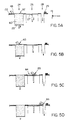
- FIGs. 5A-5D are schematic diagrams illustrating a preferred process for handling the build powder. Illustrated are the feed reservoir 24, the build chamber 26 and the overflow cavity 28 depressed in the top deck 22. A supply of build powder 60 is supported in the feed reservoir 24 by the movable feed piston 25 and the build table 27 is shown within the build chamber 26. As known in the art, the feed piston 25 moves incrementally upward in the z-axis during operation, while the build table 27 moves incrementally downward in the z-axis. A constant airflow down the overflow cavity 28 is created by the vacuum pump 34 (FIG. 2).
- the floor 25 of the feed reservoir 24 has been positioned such that a sufficient quantity 62 of build material 60 for one layer protrudes above the feed reservoir 24.
- the build table 27 has been positioned to a specific depth to receive a first layer of build material. Preferably, the build table 27 is incrementally lowered to create a plurality of successive build layers, each about 5-9 mils thick or less.
- the roller is rotated counter to its forward motion to push the quantity of build material 62 forward toward the build chamber 26.
- the roller 48 continues across the build chamber 26 to deposit a finite layer of build material 64 onto the build table 27.
- an excess amount of build material 60 is provided by and removed from the feed reservoir 24.
- This excess build material 66 is dumped by the roller 48 into the overflow cavity 28 where the airflow carries the particles to the filtration system 30 (FIG. 2).
- At least a portion of the gantry 40 also passes over the overflow cavity 28 to clean debris from the bottom of the gantry 40.
- a crusted layer is typically generated on the front bottom of the gantry as a result of airborne powder mixing with the binder material. This layer tends to become thick over time and drags on the powder bed causing indentations on the top layer of the powder bed and leading to flaws in the final part.
- Small brushes, loop material (e.g., Velcro® fastener material) or other abrasive 29 are placed on top of the top deck 22 to scrape excess debris from the bottom of the gantry. This debris is then sucked down the overflow cavity 28 when the leading edge of the gantry 40 passes over it.
- the 2-D cross-section of that layer is printed.
- the printing occurs during successive passes of the print cartridge in the y-direction during the reverse pass of the gantry in the negative x-direction.
- Other printing methods can be used instead, as described in detail below.
- the spreader roller 48 attached to the gantry, picks up powder 62 from the top of the feed piston 25 and spreads it onto the top of the build table 27 in the build chamber 26. By moving the powder 62 over such distances, this process is potentially the one to cause the most airborne powder.
- the plows 49 (FIG. 4) tend to contain the wave of powder 65. This prevents build material from spilling over onto the top deck 22 and forming a pile, which is undesirable from the standpoint of machine reliability and user satisfaction.
- the plows 49 form a seal against the ends of rotating and translating spreader roller 48 and against the top of the top deck 22. Springs are preferably utilized to generate an inward force on the plows 49 toward each other, causing the plows 49 to form a tight seal with the spreader roller 48. The springs also generate a downward force on the plows 49 to form a seal with the top of the top deck 22.
- the plows 49 are preferably fabricated from an oil-filled plastic material to reduce the friction between the bottom of the plows 49 and the top of the top deck 22 during powder spreading.
- the oil-filled material also forms a barrier which prevents powder from sticking to the bottom of the plows 49.
- the oil-filled material may also provide a self-replenishing release layer.
- the overflow cavity 28 is preferably wider than the feed reservoir 24 and build chamber 26 openings to capture this powder.
- a thin membrane 43 such as a squeegee, is located on the gantry outside the print slot 42 and the piston boxes 24,26.
- the cartridge passes over the squeegee to cause any powder and binder to be scraped off the jet outlets. The problem then remains as to how to clean the squeegee 43 and remove the powder and binder from this area.
- One preferred method of cleaning the squeegee area is to squirt a cleaning solution from a proximally located cleaning nozzle onto the squeegee 43. This solution then drains, with debris, down a waste tube and into a waste container. Another preferred method is to fire the jets so the binder material acts as a cleaning solution to rinse the debris off the squeegee 43 and down the waste tube into the waste container.
- the build time has two primary components: the spreading of the powder and the depositing of the binder liquid.
- the rate of spreading powder is limited by several factors, including the need to maintain a smooth top layer and to minimize airborne powder. Therefore, the preferred method of increasing the build rate is to increase the rate of binder deposition.
- a preferred method to increase the speed of depositing binder is to use multiple binder cartridges.
- FIG. 6 is a schematic diagram of a preferred apparatus employing multiple binder cartridges.
- the cartridges are placed at 90° relative to the single cartridge embodiment described above. That is, printing now occurs along the x-axis as the gantry 40 is moved. Because each cartridge 45'a,...,45'n is wider than the area occupied by the binder jets 47'a,...,47'n, the cartridges 45'a,...,45'n must be arranged in a special manner to be able to deposit the binder liquid over the entire surface area of the top powder layer in the build chamber 26. If the cartridges 45'a,...,45'n are simply placed side-by-side, there are areas in which the cartridges 45'a,...,45'n cannot deposit binder.
- one method of arranging the cartridges 45'a,...,45'n to provide a binding capability over a full print area 72 is to arrange the cartridges 45'a,...,45'n in several rows in the x-axis so the cartridges 45'a,...,45'n overlap to form a continuous sequence of binder jets 47'a,...,47'n along the y-axis. There is, therefore, no movement or reciprocation of any cartridge in y-axis direction during binding deposition in contrast to the single cartridge system.
- Binder is preferably supplied to each of the jets in each cartridge through a manifold 70 from a common reservoir 75.
- FIG. 7 is a schematic diagram of another preferred apparatus employing multiple binder cartridges.
- a plurality of binder cartridges 45''a,...,45''g are arranged side-by-side and then binder is deposited in two directions. That is, portions of the build area 74a,...,74g can be covered with binder as the cartridges 45''a,...,45''g move in the negative x direction, thereby binding a row of stripes.
- the cartridges 45''a,...,45''g are then indexed in the y direction by the length of the jet array 47"a,...,47"g.
- Another portion of the printable area 76 can be covered with binder upon the return of the cartridges 45"a,...,45”g in the positive x direction. This can be repeated as many times as necessary to cover the entire print area. If the last stroke is in the positive x direction, then printing occurs just ahead of spreading.
- An advantage of this technique is that there are no extra strokes and therefore there is no penalty in binding speed in using this method.
- a possible disadvantage of this method is that the powder that becomes airborne as a result of spreading can get into the jets and cause reliability problems with deposit of the binder.
- the gantry 40 returns to the feed reservoir 24 prior to spreading powder.
- Another method to deposit binder in two directions is for the gantry to bind in two strokes, return to the feed reservoir 24 and then spread powder. This has a possible disadvantage of requiring an additional number of strokes.
- This method offers an advantage in that powder which becomes airborne as a result of spreading does not interfere with the depositing of binder.
- printing can be done in one direction only for all or just for last two printing strokes.
- FIG. 8 is a schematic diagram of yet another preferred apparatus employing multiple binder cartridges.
- binder cartridges 45"'a,...,45”'m are arranged side-by-side at angles of, for example 45° relative to the x-axis.
- the binder jets 47"'a,...,47"'m are arranged in a continuous line along the y-axis to print a continuous print area 78.
- An advantage of this method is that printing can be done in one stroke or a minimal number of strokes, depending on the head geometry.
- the heads could be at an angle and print in two directions, one stripe in each direction.
- FIG. 9 is a schematic diagram of a binder cartridge having a faulty binder jet.
- the cartridge 45 is one of a plurality of cartridges which print along the x-axis as the gantry 40 (FIG. 3) moves. If a particular jet 47-6 of a cartridge 45 does not fire, then a stripe 96 may appear in the x direction on the particular layer of binder that is being printed 64. This creates an undesired discontinuity in the printed area 95. The problem is that this vertical strip of unbound powder 96 is at the same y location y f on each layer, thereby causing a plane of delamination once the part is complete.
- FIG. 10 is a schematic diagram of a preferred method of printing two layers with a faulty binder jet.
- a shingling technique is used to cause the unbound vertical stripes 96-1,96-2 to be placed in different y locations on each layer 64-1,64-2, thereby distributing the areas of weakness throughout the entire part, instead of concentrating them into one plane. Therefore, the faulty jet 47-6 is located at a different y location on each pass relative to every adjacent layer.
- Shingling with a multiple cartridge system can be accomplished by a slight offset y o of the cartridge 45 along the y-axis prior to laying each new layer of binder.
- part strength can be improved at the expense of decreasing the build rate.
- high binder volume inside a large volume results in part distortion.
- a preferred method to improve the part strength without a large increase in build rate is to increase the volume of binder as it is applied on the perimeter of each layer, thereby forming a hard shell around the part. This can be achieved by increasing the flow rate when the binder is being applied to the perimeter, or by applying the binder twice to the perimeter of the part. This method has the added advantage that it controls part distortion of the interior of the parts.
- color ink jet print heads are incorporated in the binder cartridge, thereby providing the capability of printing a wide range of colors or ink. Because a preferred system uses these heads to deposit liquid binder, they can be used to deposit a color binder as the material which causes the porous material to bind.
- the powder material is white or colorless and can absorb the ink to color the powder.
- a preferred embodiment of the invention can build three-dimensional parts which are in color, the color varying throughout the part.
- a product designer can produce models of products with various color schemes and decorations already applied to the surface. Such coloring is currently done painstakingly by hand.
- a surgeon can prepare for an operation by dissecting a 3-D color-printed model of a patient's body part to become familiar with the three-dimensional arrangement of organs, tumors, blood vessels, etc. Data for the model can be obtained from a Computed Tomography (CT) or Magnetic Resonator Imaging (MRI) scan.
- CT Computed Tomography
- MRI Magnetic Resonator Imaging
- software adjusts the color ink to use only on the outer edges of each layer, which is the only part ultimately visible to the user after the build is complete.
- a mono-colored binder e.g., black
- mono-colored binder may have superior properties and thus make for a stronger core in the parts.
- a certain quantity of liquid binder is deposited into a given volume of powder to produce a well-formed part. Too much binder results in the binder migrating beyond the intended area of the part. This effect is customarily called "bleeding.” Quantities of binder below this certain amount, however, produce progressively weaker parts. It is desirable to use an optimal quantity of binder independent of amount of color.
- One method for producing parts with controlled variations in color is as follows.
- the printer prints onto white powder and has two sets of nozzles.
- One set of nozzles deposits a black binder
- the other set of nozzles deposits white binder, which should be understood to be colorless or clear binder.
- the two types of binder are deposited in a ratio to produce the shade of gray, white, or black desired in that region of part. All regions of the part thus receive the optimal total amount of binder needed to produce a strong part.
- Such a technique requires binder jet heads which can produce controlled size droplets.
- an ink jet print head could be chosen to produce droplets of a controlled range of sizes, most heads work best if they are used to produce droplets of one size only.
- each location of the parts cross section is hit by either a black droplet or a clear droplet.
- These droplets can be distributed in such a manner that when viewed from a sufficient distance a gray is perceived, but when magnified, it is seen as a pattern of dots.
- Schemes for doing this are known as dithering and halftoning.
- Traditional methods of dithering and halftoning can be used on each layer to determine where to place the droplets of each binder. Algorithms also exist for dithering and halftoning techniques to determine the optimal placement of droplets that fall on what will be the surface of the finished part.
- inks of three primary additive colors there are inks of three primary additive colors: cyan, magenta and yellow. Mixing the three primary colors in equal quantities makes black. Mixing any two of equal quantities make the three secondary colors of purple, green and orange. By mixing different ratios of these inks and thinning to white, all possible colors can be made. Real inks, however, are slightly off in hue and vary in brightness. They, therefore, typically cannot be combined to obtain a pure black.
- Color printing with real-world inks is done by placing color dots next to each other so that they don't actually mix.
- the reflected light from the adjacent dots mixes in the eye and creates the illusion of an intermediate color, when seen from sufficient distance. If those same inks were mixed together, they would yield a muddy color.
- Schemes for arranging colored dots are called color halftoning or color dithering.
- the pigments not migrate from an area in which they are placed or mixed with adjacent droplets of a different color. This can be achieved by having the pigments set, coagulate, or come out of solution or suspension by the heating of the build powder.
- the ink liquids can be made immiscible with the binder and with the other colors of ink. Thus, pigments from the given droplet can only diffuse into another droplet of the same color.
- Post-processing techniques 7 are preferably employed to finish the 3-D object prototype 9.
- the parts can be dipped or painted with a solution which, through capillary action, infiltrates into the pores of the part.
- the solution preferably includes a supplemental material, such as an epoxy, a solvent-based material, wax, plastic, urethane, or monomers.
- a supplemental material such as an epoxy, a solvent-based material, wax, plastic, urethane, or monomers.
- the dipping process described above can take place in a bath. Parts can be put in a basket with a screen on the bottom and then the basket can be dipped into the bath. When the basket is removed, it is hung over the bath so that the excess solution drips out of the basket and back into the bath. This dipping can occur in a batch or a continuous process.
- a preferred solution for part infiltration can be an epoxy or solvent-based system.
- the epoxy can either be a two-part epoxy or a UV curable epoxy.
- the solution can be a melted material which melts at a lower temperature than that at which the parts soften. Examples of such melted material include: wax, plastic, rubber or metal.
- a part For dipping into a melted material, a part can be placed in a bath which is inside an enclosure where the air temperature is controlled. Parts are put in a basket, heated up in the air and then dipped. They can then be removed and stay warm in the warm air.
- the part can be preheated in the warm air. Preheating the part before dipping into a melted material accomplishes three goals. First, it removes moisture from the part and thereby hardens the part which can reduce the amount of sagging after treatment. Second, it removes moisture from the part which frees up additional volume which can then be infiltrated with the material. This has the result of increasing the final infiltration density in the part and thereby improving part strength. Third, preheating of the entire part prevents the infiltration material from fusing on the outer shell of the part when the part is dipped. When the part is heated, the material can infiltrate much deeper into the part which improves final part strength.
- the part can be freeze dried to remove moisture without altering the structure of the part.
- Infrared lights above the build chamber can also be used to increase the drawing rate of the binder. This can also improve the overall build rate.
- a heated airflow through the build chamber can be used to accelerate binder drawing and possibly control moisture.
- Post-heating of the part can also be used and accomplishes two goals. First, it allows draining of trapped volumes as the material inside the trap melts down and out through the bottom of the trap. Second, it improves the service finish by remelting and distributing any excess material that is frozen on the surface of the part.
- Double dipping can be accomplished by preheating the part, dipping it, post-heating it and then allowing it to cool. The part is then preheated again, dipped again and post-heated again. This provides a harder outer shell to the part which improves its appearance and handling characteristics.
- the second dip can be of the same temperature, higher temperature or lower temperature than the original dip.
- Another method to improve part strength and harden the outer shell is to utilize a multipart hardener.
- one reactive component of a binary or other multipart system can be mixed with the powder and thereby be spread with the powder in each layer.
- the second component (and any subsequent components) can be later added through post-process infiltration as described above to harden the shell.
- one reactive component of a multipart system can be mixed with the binder and thereby laid wherever the binder is deposited.
- the part is immersed in a solution in a vacuum chamber.
- the vacuum is released, the solution gets sucked into the part.
- a caddie can also be used to remove the parts. For example, a box can be placed on top of the build chamber 26, the powder is raised into the box, and then a sheet of metal is slid between the powder and the build table 27. The whole assembly can then be transferred elsewhere for powder removal.
- the walls of the build chamber 26 can be belts moving in the vertical directions to reduce shear force against the powder when lifting the powder out of the build chamber and into the caddie.
- the feed reservoir 24 and the build chamber 26 both usually contain powdered build material. It is desirable to prevent this powder from falling through the bottom of these piston boxes 24,26, because this could cause problems with the piston mechanism below and could also result in powder accumulation under the boxes. In addition, as mentioned above, any airborne powder can cause a variety of other problems.
- the feed piston 25 and build piston 27 are preferably rectangular to maximize the feed and build volumes within the constraints of the overall machine dimensions. While it is desirable for design purposes to have rectangular instead of cylindrical pistons 25,27, the feed reservoir 24 and the build chamber 26 preferably have rounded inside corners to make it easier to form a seal around the pistons 25,27, thereby preventing any powder from falling through the bottom of the piston boxes 24,26. This seal is preferably fabricated from a plastic material and is fixed to the pistons 25,27.
- FIG. 11 is a schematic diagram of a preferred technique to fabricate the feed reservoir 24 and the build chamber 26.
- the rounded interior corners are preferably cut from a section of a thin (e.g., 3-5 mils) unibody sheet metal belt 102 having a circumference equal to the desired circumference of the box interior.
- a length of the belt 102 is cut to equal the final height of the desired box 24,26.
- This section of belt 102 is then put around four rods 104 defining the corners of the boxes 24,26.
- the belt 102 is placed inside of a containing box 106 having sides whose lengths are slightly greater than the distance between the respective rods.
- Urethane 108 is then poured between the outside of the belt 102 and the inside of the containing box 106.
- the urethane 108 is left to harden. After the urethane has cured the rods 104 are removed, thus forming a box with a metal interior, rounded corners and thin walls (about .125-.25
Abstract
Description
- The invention relates to an apparatus for fabricating a three-dimensional object according to the pre-characterising part of claim 1 and to a method of assembling an apparatus for fabricating a three-dimensional object.
- Rapid prototyping describes various techniques for fabricating a three-dimensional prototype of an object from a computer model of the object. One technique is three-dimensional printing whereby a special printer is used to fabricate the prototype from a plurality of two-dimensional layers. In particular, a digital representation of a 3-D object is stored in a computer memory. Computer software sections the representation of the object into a plurality of distinct 2-D layers. A 3-D printer then fabricates a layer of material for each layer sectioned by the software. Together, the various fabricated layers form the desired prototype.
- In one method of three-dimensional printing, layers of a powder material are deposited in a confined area. A binder solution is selectively deposited on each layer to produce regions of bound powder. The unbound powder is then removed to yield a three-dimensional part.
- Various mechanisms have been used to form and print on the layers of build material.
- WO95/34468 describes an apparatus used for powder handling in a layerwise additive fabrication process such as three-dimensional printing (3DP) or selective laser sintering (SLS), comprising apparatus for dispensing bulk powder so that it can readily be spread into a series of thin layers, for conveying bulk powder so as to fill the dispensing apparatus and further for collecting excess dispensed powder not incorporated into these layers. The dispenser functions by applying a high-frequency vibration to an enclosure filled with powder, whose bottom face is perforated. It is filled by a hopper above which is itself filled from a powder supply container by the use of a vacuum. Finally excess powder falls into a gutter and removed from it by a vacuum cleaner after a seal on the gutter has closed.
- EP 0 431 924 A describes a process for making a component by (A) depositing a first layer of a powder material in a confined region and then (B) depositing a binder material to selected regions of the layer of powder material to produce a layer of bonded powder material at the selected regions. Such steps are repeated a selected number of times to produce successive layers of selected regions of bonded powder material (C) so as to form the desired component (D). The unbonded powder material is then removed (E). In some cases the component may be further processed as, for example, by heating it to further strengthen the bonding thereof.
- WO94/26446 describes a method to create three-dimensional bodies, for example models, formers, finished products, semi-finished products, among others, from a medium consisting of particles, by producing a number of cross-sectional layers, each and every one representing a cross section of an object that has to be manufactured, whereby by means of an energy producing device, which moves over the medium, the particles, in the just then topmost layer, in chosen areas, are connected at least with each other or with each other and with a preceding layer, in accordance with signals from a control unit. Particles that are not connected in respective layer are removed. The energy producing device, which comprises at least one electrode, forms one of the poles in a circuit, where the other pole is constituted of said medium, which is electrically conducting or semiconducting when these poles are connected to at least a voltage source, whereby energy waves are formed between said electrode and said medium, for example in form of at least an electric arc or heat, that connect the material particles of said medium by changing the physical characteristics of said particles in said chosen area.
- WO94/19112 describes a system for producing three dimensional components by bonding together successive layers of a porous material with droplets of a binder material. A binder printhead has an array of nozzles which controllably supply jets of binder material droplets to the layers of porous material. The printhead is scanned in a raster scan fashion over each layer of porous material along a first scan axis in one direction to provide first fast scanning paths of droplets. The printhead is then moved laterally of such one direction and is then moved along the fast scan axis in the opposite direction to provide second fast scanning paths of droplets which are interlaced with the first scanning paths. The supply of the droplets to the porous material can be controlled so as to control the overlapping thereof to produce various desired surface and interior characteristics of the opponents.
- DE 44 17 083 describes a coating device for a stereographic means of forming a three-dimensional object comprises a main container for an overflow container. Both containers are separated by an overflow edge. This edge sets the level of the fluid polymer in the main container. Overflowing fluid is extracted through a pipe with a pipe pump. The drawn-off fluid is returned to the polymer surface or to the part which is to be formed by a dispenser, which functions as an applicator on the one hand and as a smoothing element on the other. While this is happening, the dispenser moves plane-parallel with the surface of the polymer. Excess fluid flows back to the overflow container and so the cycle is completed. The thickness of coating applied is determined by the amount delivered by the pump or alternatively by the speed of the dispenser.
- WO92/08592 describes an apparatus for fabricating parts by selective laser sintering is disclosed, which includes a baffle for directing gas at the target surface. The gas is preferably controlled in temperature to cool, by convection, a layer of heat-fusible powder after it has been selectively laser sintered, to the temperature of the part formed in prior layers. The cooling preferably occurs prior to the application of the next layer of powder. The baffle directs gas flow towards the center of the target surface and exhaust ports are provided on multiple sides of the target surface so that the gas flow is substantially symmetric at the target surface. A ring exhaust hood may be suspended over the target surface, so that uniform gas flow may result and so that powder may be disposed over the target surface by way of a counterrotating roller. The baffle may direct the gas directly at the target surface, or may be constructed so that the gas spirals toward the target surface in a cyclonic fashion; further alternative baffles can be used to direct the gas at the target surface in a nonuniform fashion, including turbulent or arbitrary flow patterns.
- WO-A-95/34468 discloses an apparatus for fabricating a three-dimensional object according to the preamble of claim 1. The present invention, in a first aspect, is characterized by the features of the characterizing portion of claim 1. The present invention, in a second aspect is a method of assembling such an apparatus as claimed in claim 16.
- Particular embodiments of the invention are the subject of the dependent claims.
- Build material is stored in the feed reservoir in a powdered form and is extracted as required to build the three-dimensional object. The build table receives an incremental deposit of build powder transferred from the feed reservoir. The build powder preferably reacts with an applicable binder to form a solid region. Excess build powder which is not deposited on the build table is received at an overflow cavity. During fabrication, airborne build material is also created in the work area.
- A filtration system including a vacuum pump and a filter is preferably coupled to the overflow cavity and removes the excess build powder from the overflow cavity. The filtration system may also includes a dehumidifying element to remove excess moisture from the air. The filtration system may draw air from the overflow cavity during operation of the printer. The user can select to divert the suction to an inlet to act as a moveable, miniature vacuum cleaner.
- The filtration system preferably recirculates the filtered, dehumidified air from the work area to a clean area of the printer. The clean area can include electronics and other equipment damageable by the airborne build material. A partial seal may separate the work area from the clean area and a mechanical coupling may extend through the partial seal to operate the fabrication assembly. A positive pressure differential helps to keep airborne powder out of the clean area.
- Binder liquid is preferably applied by a moveable gantry suspended over the feed reservoir, the build table and the overflow cavity. The gantry can also include a spreader for transferring build material from the feed reservoir to the build table to create incremental layers. The gantry may include binder jets in at least one binder cartridge, each binder jet being coupled to a supply of binder to selectively deposit binder on the layers of build material.
- Varied volumes of binder may be applied to selected positions in the layers of build material. By applying these varying quantities of binder, the strength of the part can be controlled. In particular, a greater volume of binder is deposited at the perimeter of the cross-section to create a hard outer shell. Varying volumes can be deposited by varying the flow rate of the binder from the jets or by depositing binder at a variable number of times at a selected position.
- The binder can include color dyes. Drops of binder and dyes are selectively deposited on a layer of build material to create a multi-colored object. In particular, the dyes are selectively deposited to color the outside surface of the object. The binder itself can be uncolored or combined with the dyes.
- During operation, the binder jets can be clogged by debris, including a mixture of the binder and the build material. A cleaning assembly on the gantry may include a wiper membrane to remove build material and other debris from the binder jets. In particular, a wiper element may be provided in a path from the binder jets. The binder jets are periodically directed to travel across the wiper element so the wiper element can dislodge residue from the jets. The wiper element can be cleaned by flowing binder material from the jets over the wiper element to clean the wiper element. The resulting waste liquid can be collected for disposal in a waste container.
- For a number of reasons, including clogging and misalignment, a particular binder jet in a print cartridge may be faulty. The faulty jet can create an undesired line of delamination in each layer of build material. The binder jets may be offset by a fixed distance between successive layers. This offsetting creates a discontinuity between the lines of delamination. This shingling effect is created by laterally offsetting the binder jets relative to the direction of a print scan.
- The feed reservoir and the build chamber may be piston boxes fabricated from a unitary material. The piston boxes include sides which join each adjacent side at a curved interior corner. A piston is chosen to have a shape which compliments the interior shape of the box. A seal is provided between the outside edges of the piston and the interior surface of the box to retain the build material over the pistons. Preferably, the box is formed by shaping a flexible metal belt to form a smooth interior surface. The curved interior corners are formed by wrapping the belt around a plurality of rods to define the corners. The belt is then fixed in place by a volume of cured urethane and the rods are removed to yield a piston box having a smooth interior surface.
- The above and other features of embodiments of the invention, including various novel details of construction and combination of parts, will be more particularly described with reference to the accompanying drawings and pointed out in the claims. It will be understood that the particular method and apparatus for prototyping a three-dimensional object embodying the invention is shown by illustration only and not as a limitation of the invention. The principal and features of this invention may be embodied in varied and numerous embodiments without departing from the scope of the invention.
-
- FIG. 1 is a schematic diagram of an apparatus for rapid prototyping in accordance with the invention.
- FIG. 2 is a perspective view of the basic elements for regulating airflow through the three-dimensional printer.
- FIG. 3 is a top side view of the three-dimensional printer in accordance with the invention.
- FIG. 4 is a detailed top side view of a print gantry useful with the present invention.
- FIGs. 5A-5D are schematic diagram of a process for controlling print medium useful with the present invention.
- FIG. 6 is a schematic diagram of a preferred apparatus employing multiple binder cartridges.
- FIG. 7 is a schematic diagram of another preferred apparatus employing multiple binder cartridges.
- FIG. 8 is a schematic diagram of yet another preferred apparatus employing multiple binder cartridges.
- FIG. 9 is a schematic diagram of a binder cartridge having a faulty binder jet.
- FIG. 10 is a schematic diagram of a preferred method of printing two layers with a faulty binder jet.
- FIG. 11 is a schematic diagram of a preferred
technique to fabricate the
feed reservoir 24 and thebuild chamber 26. -
- FIG. 1 is a schematic diagram of an apparatus for rapid prototyping in accordance with the invention. As illustrated, there is a computer 1, a three-
dimensional printer 3, a formed 3-D printer object 5, apostprocessing system 7 and a post-processed 3-D prototype object 9. - The computer 1 is preferably a personal computer, either a desktop computer or a portable computer. The computer 1 can be a stand-alone computer or a part of a Local Area Network (LAN) or a Wide Area Network (WAN). In accordance with the invention, the computer 1 includes a
software application 12, such as a Computer Aided Design (CAD)/Computer Aided Manufacturing (CAM) program. The CAD/CAM program 12 manipulates digital representations of three-dimensional objects 17 stored in adata storage area 15. The CAD/CAM program 12 can create, modify and retrieve the storedrepresentations 17. When a user desires to fabricate aprototype object 9 of the storedobject representation 17, the user exports the stored representation to a high-level software program 18. From the high-level program 18, the user then instructs theprogram 18 to print. Theprogram 18 sections thedigital representation 17 into a plurality of discrete two-dimensional layers, each of a predetermined thickness. - The
program 18 prints each layer by sending high-level instructions to controlelectronics 52 in theprinter 3, which operates the three-dimensional printer 3. Alternatively, the digital representation of theobject 17 can be directly read from a computer-readable medium (e.g., magnetic or optical disk) by printer hardware. The three-dimensional printer 3 includes adirty area 20 where the printing is performed and aclean area 50 wherecontrol electronics 52 are housed. - The three-
dimensional printer 3 uses an ink jet type print cartridge to deposit binder solution from the ink jets onto successive layers of a powdered build material, such as disclosed in U.S. Patent Application Serial No. 08/707,693, filed on September 4, 1996, the teachings of which are incorporated herein by reference in their entirety. Where the binder combines with the build powder, the powder reacts and cures into a solid structure. By controlling the placement of binder droplets from these binder jets, the solid structure of the 2-D cross section can be physically reproduced. The three-dimensional printer 3 fabricates a physical layer for each sectioned layer provided by theprogram 18. When the file has been completely printed, an unfinished three-dimensional part 5 is formed. Further details of binding a powder to form an object are disclosed in U.S. Patent Nos. 5,340,656 to Sachs et al. and 5,387,380 to Cima et al., the teachings of which are incorporated herein by reference in their entirety. - The
post-processing system 7 is typically required to finish theprototype object 9 from the printedpart 5. Various finishing options are available depending on the result to be achieved. Preferred options will be described in more detail below. - In accordance with a preferred embodiment of the invention, air can be circulated throughout the machine to maintain a humidity controlled environment and to solve a variety of problems. One of the major problems addressed by the invention is that of airborne powder which can cause reliability problems. Airborne powder can get into the binder jets and thereby cause them to clog and hinder printing. Also, the powder can cause damage to the printer electronics and other sensitive hardware. Finally, loose powder can be released into the environment when a top enclosure covering the printer is open, thereby causing an annoyance to the user.
- FIG. 2 is a perspective view of the preferred airflow system for the three-
dimensional printer 3. As illustrated, the three-dimensional printer 3 includes atop deck 22 having a plurality of depressed cavities. Illustrated along the x-axis are arectangular feed reservoir 24 having abottom feed piston 25, arectangular build chamber 26 having a bottom build piston defining a build table 27, and a funnel-shapedoverflow cavity 28. Although omitted from the drawing for clarity, a seal is fixed to thepistons piston boxes - The
overflow cavity 28 is connected to an air filtration andconditioning system 30. Avacuum pump 34 draws air from theoverflow cavity 28 through aninflow conduit 31 into afilter chamber 32. Foreign matter is extracted from the air by thefilter chamber 32, such as through a collection bag and filter arrangement. The filtered air from thevacuum pump 34 is provided by afilter conduit 35 to adesiccant cartridge 36 to control the humidity of the filtered air. The dehumidified filtered air is provided by anoutflow conduit 37 to a port leading to theclean area 50. - In addition to capturing excess powder, the airflow through the
overflow cavity 28 reduces the amount of airborne powder to facilitate machine reliability and user satisfaction. - The airflow through the
overflow cavity 28 can be shutoff by the user pressing a button or operating a switch (not shown) which closes avalve 39. Suction is diverted to an alternative inflow tube 31' which terminates at aninlet 38 which can be extended and manipulated by the user as a miniature vacuum cleaner to vacuum excess, unbound powder from in and around thebuild chamber 26 once the building of thepart 5 is complete. To facilitate this cleaning process, the alternative inflow tube 31' is of a smaller diameter than theinflow conduit 31 so the airflow automatically jumps to a much higher velocity when thisminiature vacuum 38 is being used. The airflow returns to its lower level when the user switches thevalve 39 back to generate flow from theoverflow cavity 38. Preferably, thevalve 39 automatically switches to theoverflow cavity 28 when building recommences. - FIG. 3 is a top view of the three-dimensional,
printer 3 of FIG. 1. Shown in more detail are thedirty area 20 and the rearclean area 50, with both tops removed. Thetop deck 22, in addition to the threeboxes abrasive section 29 discussed below. Aprint gantry 40 is suspended over thetop deck 22 by anarm assembly 55 connected to atrack 57 and asupport rod 23. During operation, the arm moves along the x-axis on thetrack 57 and thesupport rod 23 to move thegantry 40. - The
dirty area 20 is separated from theclean area 50 by a slidingseal 90 through which thearm assembly 55 extends. The sliding seal may be a slit formed in a plastic sheet. Theoperational electronics 52 are located in theclean area 50. Because of a pressure differential between thedirty area 20 and theclean area 50, airflows from theclean area 50 through the slidingseal 90 into thedirty area 20. This positive pressure differential is maintained to keep powder particles and dust out of theclean area 50. This airflow into theclean area 50 from theairflow system 30 also helps to cool theelectronics 52. - As illustrated, the
gantry 40 includes aprint slot 42 which defines a printable area, and abinder cartridge 45. Thebinder cartridge 45 reciprocates in the y-axis along aprint track 46. During printing, the y-axis is a faster print axis than the x-axis of the gantry movement. Thegantry 40 preferably includes at least one inkjet print cartridge 45, each having a plurality of binder jets for depositing a binder liquid. The binder jets receive binder solution from a binder reservoir 75 (FIG. 2) through at least onebinder conduit 77. Also illustrated is aspreader roller 48 for dispersing build powder from thefeed reservoir 24 to thebuild chamber 26. - FIG. 4 is an enlarged schematic diagram of the
print gantry 40 of FIG. 3. Illustrated are a row ofbinder jets 47 in thecartridge 45. Included is ajet wiper 43, for example, a flexible rubber blade, which removes residue from thebinder jets 47 during each reciprocation cycle. Also shown is anenclosure 44 over the scan area of theprinter cartridge 45. Theroller 48 is flanked by twoplow members 49 which cooperate to prevent an accumulation of excess print medium from the edges of thefeed curl 24 and thebuild cavity 26, as described in more detail below. - Air also flows from the
clean area 50 to thecartridge enclosure 44 through anair tube 58. A positive airflow can be matched by the pressure differential between theclean area 50 and thedirty area 20, although afan 59 placed on theclean area 50 can be used to assist the airflow out of thecartridge enclosure 44 to provide a positive pressure and thereby hinder powder from entering theenclosure 44. This hinders airborne powder, resulting from the impact of the liquid binder hitting the powder, from traveling onto the binder jets and thereby clogging them. - FIGs. 5A-5D are schematic diagrams illustrating a preferred process for handling the build powder. Illustrated are the
feed reservoir 24, thebuild chamber 26 and theoverflow cavity 28 depressed in thetop deck 22. A supply ofbuild powder 60 is supported in thefeed reservoir 24 by themovable feed piston 25 and the build table 27 is shown within thebuild chamber 26. As known in the art, thefeed piston 25 moves incrementally upward in the z-axis during operation, while the build table 27 moves incrementally downward in the z-axis. A constant airflow down theoverflow cavity 28 is created by the vacuum pump 34 (FIG. 2). - Referring to FIG. 5A, the
floor 25 of thefeed reservoir 24 has been positioned such that asufficient quantity 62 ofbuild material 60 for one layer protrudes above thefeed reservoir 24. The build table 27 has been positioned to a specific depth to receive a first layer of build material. Preferably, the build table 27 is incrementally lowered to create a plurality of successive build layers, each about 5-9 mils thick or less. - Referring to FIG. 5B, the roller is rotated counter to its forward motion to push the quantity of
build material 62 forward toward thebuild chamber 26. As illustrated in FIG. 5C, theroller 48 continues across thebuild chamber 26 to deposit a finite layer ofbuild material 64 onto the build table 27. To assure that a full build layer is deposited on the build table 27, an excess amount ofbuild material 60 is provided by and removed from thefeed reservoir 24. Thisexcess build material 66 is dumped by theroller 48 into theoverflow cavity 28 where the airflow carries the particles to the filtration system 30 (FIG. 2). - At least a portion of the
gantry 40 also passes over theoverflow cavity 28 to clean debris from the bottom of thegantry 40. A crusted layer is typically generated on the front bottom of the gantry as a result of airborne powder mixing with the binder material. This layer tends to become thick over time and drags on the powder bed causing indentations on the top layer of the powder bed and leading to flaws in the final part. Small brushes, loop material (e.g., Velcro® fastener material) or other abrasive 29 are placed on top of thetop deck 22 to scrape excess debris from the bottom of the gantry. This debris is then sucked down theoverflow cavity 28 when the leading edge of thegantry 40 passes over it. - Having layed a current layer with movement of the gantry in the x-direction, the 2-D cross-section of that layer is printed. In particular, the printing occurs during successive passes of the print cartridge in the y-direction during the reverse pass of the gantry in the negative x-direction. Other printing methods can be used instead, as described in detail below.
- As noted, the
spreader roller 48, attached to the gantry, picks uppowder 62 from the top of thefeed piston 25 and spreads it onto the top of the build table 27 in thebuild chamber 26. By moving thepowder 62 over such distances, this process is potentially the one to cause the most airborne powder. - As the build material is being spread, a wave of
powder 65 results and tends to move laterally relative to the roller's direction of motion. The plows 49 (FIG. 4) tend to contain the wave ofpowder 65. This prevents build material from spilling over onto thetop deck 22 and forming a pile, which is undesirable from the standpoint of machine reliability and user satisfaction. Theplows 49 form a seal against the ends of rotating and translatingspreader roller 48 and against the top of thetop deck 22. Springs are preferably utilized to generate an inward force on theplows 49 toward each other, causing theplows 49 to form a tight seal with thespreader roller 48. The springs also generate a downward force on theplows 49 to form a seal with the top of thetop deck 22. - The
plows 49 are preferably fabricated from an oil-filled plastic material to reduce the friction between the bottom of theplows 49 and the top of thetop deck 22 during powder spreading. The oil-filled material also forms a barrier which prevents powder from sticking to the bottom of theplows 49. In addition, the oil-filled material may also provide a self-replenishing release layer. - As the
spread roller 48 pushes the wave ofpowder 65, there is an accumulation of powder on the leading edge which gets pushed sideways onto the area in front of theplows 49. This powder is pushed along by theplows 49 until it is finally sucked through theoverflow cavity 28 or piled out of the way. Theoverflow cavity 28 is preferably wider than thefeed reservoir 24 and buildchamber 26 openings to capture this powder. - The impact of the binder hitting the powder layer during binding causes powder to fly up and hit the bottom of the binder cartridge. Because the cartridge is wet with binder, the powder can then harden and form a crust on the bottom of the cartridge or it could possibly eventually get inside the jets, thereby clogging the outlet of the jets. In addition, excess binder occasionally forms a droplet which rests on the bottom of the cartridge and remains there as a result of surface tension. This can also cause clogging of the outlet of the jets or deflection of the jets. When jets are clogged, the binder is not deposited where desired, thereby causing faults in the final part. Therefore, a method is desired to clean the powder or binder from the bottom of the cartridge after the laying of each layer of powder to keep the jet outlets open.
- Returning to FIG. 4, a
thin membrane 43, such as a squeegee, is located on the gantry outside theprint slot 42 and thepiston boxes squeegee 43 and remove the powder and binder from this area. - One preferred method of cleaning the squeegee area is to squirt a cleaning solution from a proximally located cleaning nozzle onto the
squeegee 43. This solution then drains, with debris, down a waste tube and into a waste container. Another preferred method is to fire the jets so the binder material acts as a cleaning solution to rinse the debris off thesqueegee 43 and down the waste tube into the waste container. - Maximizing build speed is of great interest to the user. The build time has two primary components: the spreading of the powder and the depositing of the binder liquid. The rate of spreading powder is limited by several factors, including the need to maintain a smooth top layer and to minimize airborne powder. Therefore, the preferred method of increasing the build rate is to increase the rate of binder deposition. A preferred method to increase the speed of depositing binder is to use multiple binder cartridges.
- FIG. 6 is a schematic diagram of a preferred apparatus employing multiple binder cartridges. When employing multiple cartridges, the cartridges are placed at 90° relative to the single cartridge embodiment described above. That is, printing now occurs along the x-axis as the
gantry 40 is moved. Because each cartridge 45'a,...,45'n is wider than the area occupied by the binder jets 47'a,...,47'n, the cartridges 45'a,...,45'n must be arranged in a special manner to be able to deposit the binder liquid over the entire surface area of the top powder layer in thebuild chamber 26. If the cartridges 45'a,...,45'n are simply placed side-by-side, there are areas in which the cartridges 45'a,...,45'n cannot deposit binder. - As illustrated, one method of arranging the cartridges 45'a,...,45'n to provide a binding capability over a
full print area 72 is to arrange the cartridges 45'a,...,45'n in several rows in the x-axis so the cartridges 45'a,...,45'n overlap to form a continuous sequence of binder jets 47'a,...,47'n along the y-axis. There is, therefore, no movement or reciprocation of any cartridge in y-axis direction during binding deposition in contrast to the single cartridge system. Binder is preferably supplied to each of the jets in each cartridge through a manifold 70 from acommon reservoir 75. - FIG. 7 is a schematic diagram of another preferred apparatus employing multiple binder cartridges. As illustrated, a plurality of binder cartridges 45''a,...,45''g are arranged side-by-side and then binder is deposited in two directions. That is, portions of the build area 74a,...,74g can be covered with binder as the cartridges 45''a,...,45''g move in the negative x direction, thereby binding a row of stripes. The cartridges 45''a,...,45''g are then indexed in the y direction by the length of the
jet array 47"a,...,47"g. Another portion of theprintable area 76 can be covered with binder upon the return of thecartridges 45"a,...,45"g in the positive x direction. This can be repeated as many times as necessary to cover the entire print area. If the last stroke is in the positive x direction, then printing occurs just ahead of spreading. - An advantage of this technique is that there are no extra strokes and therefore there is no penalty in binding speed in using this method. A possible disadvantage of this method is that the powder that becomes airborne as a result of spreading can get into the jets and cause reliability problems with deposit of the binder.
- If the last stroke is in the positive x direction, then the
gantry 40 returns to thefeed reservoir 24 prior to spreading powder. Another method to deposit binder in two directions is for the gantry to bind in two strokes, return to thefeed reservoir 24 and then spread powder. This has a possible disadvantage of requiring an additional number of strokes. This method, however, offers an advantage in that powder which becomes airborne as a result of spreading does not interfere with the depositing of binder. Alternatively, printing can be done in one direction only for all or just for last two printing strokes. - FIG. 8 is a schematic diagram of yet another preferred apparatus employing multiple binder cartridges. As illustrated,
binder cartridges 45"'a,...,45"'m are arranged side-by-side at angles of, for example 45° relative to the x-axis. As such, thebinder jets 47"'a,...,47"'m are arranged in a continuous line along the y-axis to print acontinuous print area 78. An advantage of this method is that printing can be done in one stroke or a minimal number of strokes, depending on the head geometry. - One of ordinary skill in the art would recognize many variations to the methods described above to optimize various parameters. For example, the heads could be at an angle and print in two directions, one stripe in each direction.
- It is desired to achieve consistently high part strength despite various problems with the printing of particular jets. For example, occasionally certain jets in the binder cartridge may not be firing or the firing may be flickered as a result of a head that is manufactured poorly or one that has become contaminated by powder.
- FIG. 9 is a schematic diagram of a binder cartridge having a faulty binder jet. As illustrated, the
cartridge 45 is one of a plurality of cartridges which print along the x-axis as the gantry 40 (FIG. 3) moves. If a particular jet 47-6 of acartridge 45 does not fire, then astripe 96 may appear in the x direction on the particular layer of binder that is being printed 64. This creates an undesired discontinuity in the printedarea 95. The problem is that this vertical strip of unboundpowder 96 is at the same y location yf on each layer, thereby causing a plane of delamination once the part is complete. - FIG. 10 is a schematic diagram of a preferred method of printing two layers with a faulty binder jet. In accordance with the invention, a shingling technique is used to cause the unbound vertical stripes 96-1,96-2 to be placed in different y locations on each layer 64-1,64-2, thereby distributing the areas of weakness throughout the entire part, instead of concentrating them into one plane. Therefore, the faulty jet 47-6 is located at a different y location on each pass relative to every adjacent layer. Shingling with a multiple cartridge system can be accomplished by a slight offset yo of the
cartridge 45 along the y-axis prior to laying each new layer of binder. - It is also desirable to optimize the part strength while maintaining a high build rate. By depositing more binder per unit area, part strength can be improved at the expense of decreasing the build rate. In addition, high binder volume inside a large volume results in part distortion. A preferred method to improve the part strength without a large increase in build rate is to increase the volume of binder as it is applied on the perimeter of each layer, thereby forming a hard shell around the part. This can be achieved by increasing the flow rate when the binder is being applied to the perimeter, or by applying the binder twice to the perimeter of the part. This method has the added advantage that it controls part distortion of the interior of the parts.
- In this embodiment of the invention, color ink jet print heads are incorporated in the binder cartridge, thereby providing the capability of printing a wide range of colors or ink. Because a preferred system uses these heads to deposit liquid binder, they can be used to deposit a color binder as the material which causes the porous material to bind. Preferably, the powder material is white or colorless and can absorb the ink to color the powder. As a result, a preferred embodiment of the invention can build three-dimensional parts which are in color, the color varying throughout the part.
- A product designer can produce models of products with various color schemes and decorations already applied to the surface. Such coloring is currently done painstakingly by hand. In addition, a surgeon can prepare for an operation by dissecting a 3-D color-printed model of a patient's body part to become familiar with the three-dimensional arrangement of organs, tumors, blood vessels, etc. Data for the model can be obtained from a Computed Tomography (CT) or Magnetic Resonator Imaging (MRI) scan.
- In accordance with a preferred embodiment of the invention, software adjusts the color ink to use only on the outer edges of each layer, which is the only part ultimately visible to the user after the build is complete. In such a case, a mono-colored binder (e.g., black) is used on the inside of part which is not visible to the user. This conserves color binder which can be more expensive and more cumbersome for the user to obtain for refill. In addition, mono-colored binder may have superior properties and thus make for a stronger core in the parts.
- In accordance with the preferred embodiment of the invention, a certain quantity of liquid binder is deposited into a given volume of powder to produce a well-formed part. Too much binder results in the binder migrating beyond the intended area of the part. This effect is customarily called "bleeding." Quantities of binder below this certain amount, however, produce progressively weaker parts. It is desirable to use an optimal quantity of binder independent of amount of color. One method for producing parts with controlled variations in color is as follows.
- The printer prints onto white powder and has two sets of nozzles. One set of nozzles deposits a black binder, the other set of nozzles deposits white binder, which should be understood to be colorless or clear binder. At each location in the part being built, the two types of binder are deposited in a ratio to produce the shade of gray, white, or black desired in that region of part. All regions of the part thus receive the optimal total amount of binder needed to produce a strong part. Such a technique, however, requires binder jet heads which can produce controlled size droplets.
- Although an ink jet print head could be chosen to produce droplets of a controlled range of sizes, most heads work best if they are used to produce droplets of one size only. Thus, if the droplets are distributed uniformly across the layer, each location of the parts cross section is hit by either a black droplet or a clear droplet. These droplets can be distributed in such a manner that when viewed from a sufficient distance a gray is perceived, but when magnified, it is seen as a pattern of dots. Schemes for doing this are known as dithering and halftoning. Traditional methods of dithering and halftoning can be used on each layer to determine where to place the droplets of each binder. Algorithms also exist for dithering and halftoning techniques to determine the optimal placement of droplets that fall on what will be the surface of the finished part.
- By adding additional nozzles that deposit other colors of binder, the above schemes can be extended to produce full-color parts.
- A problem arises when the quantity of colored binder needed to produce a well-colored part is greater than that needed to produce a well-formed part. In that case a compromise must be made, either in the coloring or among bleeding. If the pigmented liquids do not function as a binder, it is possible to deposit much larger quantities without affecting mechanical properties of the part.
- In an ideal world, there are inks of three primary additive colors: cyan, magenta and yellow. Mixing the three primary colors in equal quantities makes black. Mixing any two of equal quantities make the three secondary colors of purple, green and orange. By mixing different ratios of these inks and thinning to white, all possible colors can be made. Real inks, however, are slightly off in hue and vary in brightness. They, therefore, typically cannot be combined to obtain a pure black.
- Color printing with real-world inks is done by placing color dots next to each other so that they don't actually mix. The reflected light from the adjacent dots mixes in the eye and creates the illusion of an intermediate color, when seen from sufficient distance. If those same inks were mixed together, they would yield a muddy color. Schemes for arranging colored dots are called color halftoning or color dithering.
- It is desirable that the pigments not migrate from an area in which they are placed or mixed with adjacent droplets of a different color. This can be achieved by having the pigments set, coagulate, or come out of solution or suspension by the heating of the build powder. Alternatively, the ink liquids can be made immiscible with the binder and with the other colors of ink. Thus, pigments from the given droplet can only diffuse into another droplet of the same color.
- It is desirable to have strong parts which do not flake when handled and which have the potential to be finished (e.g., sanded, painted or drilled) for a good final appearance. The output from the
build chamber 26, however, may have porous parts which can be weak. In addition, the part surface can be rough and flaky. Post-processing techniques 7 (FIG. 1) are preferably employed to finish the 3-D object prototype 9. - The parts can be dipped or painted with a solution which, through capillary action, infiltrates into the pores of the part. The solution preferably includes a supplemental material, such as an epoxy, a solvent-based material, wax, plastic, urethane, or monomers. Once the solution forms bonds between the powder particles, dries and hardens, the resulting part has improved strength. In addition, this process hardens the outer shell, which allows the part to be sanded, painted and drilled. This also allows the part to be handled without powder rubbing off the part, which can be a nuisance to the user and can result in gradual decay of the part.
- The dipping process described above can take place in a bath. Parts can be put in a basket with a screen on the bottom and then the basket can be dipped into the bath. When the basket is removed, it is hung over the bath so that the excess solution drips out of the basket and back into the bath. This dipping can occur in a batch or a continuous process.
- A preferred solution for part infiltration can be an epoxy or solvent-based system. The epoxy can either be a two-part epoxy or a UV curable epoxy. Alternatively, the solution can be a melted material which melts at a lower temperature than that at which the parts soften. Examples of such melted material include: wax, plastic, rubber or metal. For dipping into a melted material, a part can be placed in a bath which is inside an enclosure where the air temperature is controlled. Parts are put in a basket, heated up in the air and then dipped. They can then be removed and stay warm in the warm air.
- In accordance with a preferred embodiment of the invention, the part can be preheated in the warm air. Preheating the part before dipping into a melted material accomplishes three goals. First, it removes moisture from the part and thereby hardens the part which can reduce the amount of sagging after treatment. Second, it removes moisture from the part which frees up additional volume which can then be infiltrated with the material. This has the result of increasing the final infiltration density in the part and thereby improving part strength. Third, preheating of the entire part prevents the infiltration material from fusing on the outer shell of the part when the part is dipped. When the part is heated, the material can infiltrate much deeper into the part which improves final part strength.
- In accordance with an alternative embodiment of the invention, the part can be freeze dried to remove moisture without altering the structure of the part. Infrared lights above the build chamber can also be used to increase the drawing rate of the binder. This can also improve the overall build rate. In addition, a heated airflow through the build chamber can be used to accelerate binder drawing and possibly control moisture.
- Post-heating of the part can also be used and accomplishes two goals. First, it allows draining of trapped volumes as the material inside the trap melts down and out through the bottom of the trap. Second, it improves the service finish by remelting and distributing any excess material that is frozen on the surface of the part.
- Double dipping can be accomplished by preheating the part, dipping it, post-heating it and then allowing it to cool. The part is then preheated again, dipped again and post-heated again. This provides a harder outer shell to the part which improves its appearance and handling characteristics. The second dip can be of the same temperature, higher temperature or lower temperature than the original dip. Each of these alternatives is expected to have different results on the final part characteristics.
- Another method to improve part strength and harden the outer shell is to utilize a multipart hardener. For example, one reactive component of a binary or other multipart system can be mixed with the powder and thereby be spread with the powder in each layer. The second component (and any subsequent components) can be later added through post-process infiltration as described above to harden the shell. Alternatively, one reactive component of a multipart system can be mixed with the binder and thereby laid wherever the binder is deposited.
- In accordance with an alternative embodiment of the invention, the part is immersed in a solution in a vacuum chamber. When the vacuum is released, the solution gets sucked into the part.
- There are several methods for removing completed parts from the build chamber. One method is to vacuum the unbound particles from around the part and then pick out the part. A caddie can also be used to remove the parts. For example, a box can be placed on top of the
build chamber 26, the powder is raised into the box, and then a sheet of metal is slid between the powder and the build table 27. The whole assembly can then be transferred elsewhere for powder removal. - In accordance with a preferred embodiment of the invention, the walls of the
build chamber 26 can be belts moving in the vertical directions to reduce shear force against the powder when lifting the powder out of the build chamber and into the caddie. - The
feed reservoir 24 and thebuild chamber 26 both usually contain powdered build material. It is desirable to prevent this powder from falling through the bottom of thesepiston boxes - The
feed piston 25 and buildpiston 27 are preferably rectangular to maximize the feed and build volumes within the constraints of the overall machine dimensions. While it is desirable for design purposes to have rectangular instead ofcylindrical pistons feed reservoir 24 and thebuild chamber 26 preferably have rounded inside corners to make it easier to form a seal around thepistons piston boxes pistons - FIG. 11 is a schematic diagram of a preferred technique to fabricate the
feed reservoir 24 and thebuild chamber 26. The rounded interior corners are preferably cut from a section of a thin (e.g., 3-5 mils) unibodysheet metal belt 102 having a circumference equal to the desired circumference of the box interior. A length of thebelt 102 is cut to equal the final height of the desiredbox belt 102 is then put around fourrods 104 defining the corners of theboxes belt 102 is placed inside of a containingbox 106 having sides whose lengths are slightly greater than the distance between the respective rods.Urethane 108 is then poured between the outside of thebelt 102 and the inside of the containingbox 106. Theurethane 108 is left to harden. After the urethane has cured therods 104 are removed, thus forming a box with a metal interior, rounded corners and thin walls (about .125-.25 inch). - While this invention has been particularly shown and described with references to preferred embodiments thereof, it will be understood by those skilled in the art that various changes in form and details may be made without departing from the scope of the invention as defined by the appended claims. These and all other equivalents are intended to be encompassed by the following claims.
Claims (30)
- An apparatus for fabricating a three-dimensional object from a representation of the object stored in memory and including a feed reservoir, a build table and an overlow cavity, the apparatus being characterized by:a work surface (22) having a first, second and third aperture therethrough;the feed reservoir (24) being registered to the first aperture of the work surface (22) and having stored therein a supply of build material (60) for forming the object;a build chamber (26) registered to the second aperture of the work surface (22);the build table (27) being in the build chamber (26) for receiving incremental layers of the build material from the feed reservoir (24) ; andthe overflow cavity (28) being registered to the third aperture of the work surface (22) for receiving an excess quantity of build material transferred from the feed reservoir (24) but not received by the build table (27).
- The apparatus of Claim 1 further comprising a vacuum pump (34) coupled to the overflow cavity (28) to create an air flow path from the overflow cavity.
- The apparatus of Claim 2 further comprising a filter (32) to remove the excess quantity of build material from the air flow.
- The apparatus of Claim 3 further comprising a dehumidifying element (36) to remove moisture from the filtered air flow.
- The apparatus of Claim 2 wherein the vacuum pump (34) recirculates air from the air flow.
- The apparatus of Claim 2 wherein the vacuum pump (34) is decoupleable from the overflow cavity and coupleable to a manually moveable inlet (38).
- The apparatus of Claim 1 further comprising a plow member (49) interfacing with the work surface (22) to prevent an accumulation of loose build material around the build chamber (26).
- The apparatus of Claim 1 further comprising:a plurality of binder cartridges (45"'a to 45"'m), each cartridge having a plurality of binder jets (47"'a to 47"'m), each binder jet coupled to a supply of binder solution; anda control unit for controlling each binder jet to deposit a controlled quantity of the binder solution at controlled locations on each incremental layer of build material.
- The apparatus of Claim 1 further comprising:a work area (20) at a first air pressure housing the work surface, the work area having airborne build material therein;a clean area (50) at a second air pressure housing equipment damageable by the airborne build material; anda partial seal (90) separating the work area from the clean area so there is an air flow from the clean area (50) to the work area (20), there being a mechanical coupling through the partial seal (90).
- The apparatus of Claim 1 wherein the feed reservoir (24) and the build chamber (26) each have a wall formed from a respective unitary band of material.
- The apparatus of Claim 1 further comprising:a plurality of binder jets (47) coupled to color additives; anda control unit (52) controlling the deposit of a controlled quantity of the color additives at controlled locations on a layer of build material.
- The apparatus of Claim 1 further comprising a movable gantry (40) mounted relative to the feed reservoir, the build chamber and the overflow cavity, the gantry comprising:a plurality of binder jets (47) coupled to a supply of binder (75) for depositing binder at selected locations on the build material on the build table; anda cleaning assembly (43) for removing build material from the binder jets (47).
- The apparatus of Claim 12 wherein the cleaning assembly (43) comprises a wiper element cleanable by a flow of a solution cleaning.
- The apparatus of Claim 13 wherein the cleaning solution is binder and the binder flows from at least one of the binder jets (47).
- The apparatus of Claim 12 further comprising an abrasive element (29) mounted to the work surface (22) and adjacent to the overflow cavity (28), the abrasive element (29) interfacing with the gantry (40) to remove debris from the gantry (40).
- A method of assembling an apparatus for fabricating a three-dimensional object from a representation of the object stored in memory, comprising the steps of:forming a first, second and third aperture through a work surface (22);registering a feed reservoir (24) to the first aperture, a build chamber (26) to the second aperture, and an overflow cavity (28) to the third aperture of the work surface (22);in the feed reservoir (24), storing a supply of build material (60) for forming the object;on a build table (27) in the build chamber (26), receiving incremental layers of the build material from the feed reservoir (24); andat the overflow cavity (28), receiving an excess quantity of build material transferred from the feed reservoir (24) but not received by the build table (27).
- The method of Claim 16 further comprising the step of coupling a vacuum pump (34) to the overflow cavity (28) to create an air flow path from the overflow cavity (28).
- The method of Claim 17 further comprising the step of disposing a filter (32)in the air flow path for filtering the excess quantity of build material from the air flow.
- The method of Claim 18 further comprising the step of disposing a dehumidifier (36) in the air flow path for removing moisture from the filtered air flow.
- The method of Claim 17 wherein the vacuum pump (34) recirculates air along the air flow.
- The method of Claim 17 further comprising the steps of:disposing a valve (39) between the vacuum pump (34) and the overflow cavity (28); andthrough the valve (39), coupling the vacuum pump (34) to a manually moveable inlet (38).
- The method of Claim 16 further comprising the step of interfacing a plow member (49) with the work surface (22) to prevent accumulation of loose build material around the build chamber (26).
- The method of Claim 16 further comprising the steps of:providing a plurality of binder jets (47"'a to 47"'m);arranging the binder jets in a plurality of binder cartridges (45"'a to 45"'m);coupling each binder jet to a supply of binder solution; andcontrolling each binder jet to deposit a controlled quantity of the binder solution at controlled locations on each incremental layer of build material.
- The method of Claim 16 further comprising the steps of:housing the work surface (22) in a work area (20) at a first air pressure having airborne build material therein;housing equipment damageable by the airborne build material in a clean area (50) at a second air pressure; andforming an air flow from the clean area (50) to the work area (20) through a partial seal (90) which separates the work area (20) from the clean area (50), there being a mechanical coupling through the partial seal.
- The method of Claim 16 further comprising the step of forming a wall of the feed reservoir (24) and the build chamber (26) from a respective unitary band of material.
- The method of Claim 16 further comprising the step of:coupling a plurality of binder jets (47) to color additives; anddepositing a controlled quantity of the color additives at controlled locations on a layer of build material.
- The method of Claim 16 further comprising the step of mounting a movable gantry (40) relative to the feed reservoir (24), the build chamber (29) and the overflow cavity (28), the gantry (40) comprising:a plurality of binder jets (47) coupled to a supply of binder (75) for depositing binder at selected locations on the build material on the build table; anda cleaning assembly (43) for removing build material from the binder jets (47).
- The method of Claim 27 wherein the cleaning assembly (43) comprises a wiper element and further comprising a cleaning solution to clean build material from the wiper element.
- The method of Claim 28 wherein the cleaning solution is binder flowing from at least one of the binder jets (47).
- The method of Claim 26 further comprising the step of disposing, on the work surface, an abrasive element (29) adjacent to the overflow cavity (28) for removing debris from the gantry (40).
Priority Applications (3)
| Application Number | Priority Date | Filing Date | Title |
|---|---|---|---|
| EP02015693A EP1264679B8 (en) | 1996-12-20 | 1997-12-19 | Method and apparatus for prototyping a three-dimensional object |
| EP05077318A EP1621311B1 (en) | 1996-12-20 | 1997-12-19 | Method and apparatus for prototyping a three-dimensional object |
| EP07075583A EP1847370A3 (en) | 1996-12-20 | 1997-12-19 | Method and apparatus for prototyping a three dimensional object |
Applications Claiming Priority (3)
| Application Number | Priority Date | Filing Date | Title |
|---|---|---|---|
| US08/771,009 US6007318A (en) | 1996-12-20 | 1996-12-20 | Method and apparatus for prototyping a three-dimensional object |
| US771009 | 1996-12-20 | ||
| PCT/US1997/023922 WO1998028124A2 (en) | 1996-12-20 | 1997-12-19 | Method and apparatus for prototyping a three-dimensional object |
Related Child Applications (1)
| Application Number | Title | Priority Date | Filing Date |
|---|---|---|---|
| EP02015693A Division EP1264679B8 (en) | 1996-12-20 | 1997-12-19 | Method and apparatus for prototyping a three-dimensional object |
Publications (3)
| Publication Number | Publication Date |
|---|---|
| EP0949993A2 EP0949993A2 (en) | 1999-10-20 |
| EP0949993B1 true EP0949993B1 (en) | 2002-11-06 |
| EP0949993B2 EP0949993B2 (en) | 2006-01-25 |
Family
ID=25090409
Family Applications (4)
| Application Number | Title | Priority Date | Filing Date |
|---|---|---|---|
| EP02015693A Expired - Lifetime EP1264679B8 (en) | 1996-12-20 | 1997-12-19 | Method and apparatus for prototyping a three-dimensional object |
| EP97953459A Expired - Lifetime EP0949993B2 (en) | 1996-12-20 | 1997-12-19 | Apparatus for fabricating a three-dimensional object and method of assembling an apparatus for fabricating a three-dimensional object |
| EP07075583A Withdrawn EP1847370A3 (en) | 1996-12-20 | 1997-12-19 | Method and apparatus for prototyping a three dimensional object |
| EP05077318A Expired - Lifetime EP1621311B1 (en) | 1996-12-20 | 1997-12-19 | Method and apparatus for prototyping a three-dimensional object |
Family Applications Before (1)
| Application Number | Title | Priority Date | Filing Date |
|---|---|---|---|
| EP02015693A Expired - Lifetime EP1264679B8 (en) | 1996-12-20 | 1997-12-19 | Method and apparatus for prototyping a three-dimensional object |
Family Applications After (2)
| Application Number | Title | Priority Date | Filing Date |
|---|---|---|---|
| EP07075583A Withdrawn EP1847370A3 (en) | 1996-12-20 | 1997-12-19 | Method and apparatus for prototyping a three dimensional object |
| EP05077318A Expired - Lifetime EP1621311B1 (en) | 1996-12-20 | 1997-12-19 | Method and apparatus for prototyping a three-dimensional object |
Country Status (9)
| Country | Link |
|---|---|
| US (4) | US6007318A (en) |
| EP (4) | EP1264679B8 (en) |
| JP (2) | JP2001507295A (en) |
| AT (3) | ATE307020T1 (en) |
| CA (1) | CA2275565A1 (en) |
| DE (3) | DE69739417D1 (en) |
| ES (2) | ES2248457T3 (en) |
| HK (1) | HK1088863A1 (en) |
| WO (1) | WO1998028124A2 (en) |
Cited By (10)
| Publication number | Priority date | Publication date | Assignee | Title |
|---|---|---|---|---|
| US6989115B2 (en) | 1996-12-20 | 2006-01-24 | Z Corporation | Method and apparatus for prototyping a three-dimensional object |
| US7387359B2 (en) | 2004-09-21 | 2008-06-17 | Z Corporation | Apparatus and methods for servicing 3D printers |
| DE102008019330A1 (en) * | 2008-04-16 | 2009-10-22 | Voxeljet Technology Gmbh | Method for building models in layers, involves applying material in layers on constructional platform and after that another material is applied in layers on constructional platform selectively |
| US7824001B2 (en) | 2004-09-21 | 2010-11-02 | Z Corporation | Apparatus and methods for servicing 3D printers |
| EP2946909A1 (en) | 2014-05-22 | 2015-11-25 | 3d-figo GmbH | Device for constructing three-dimensional objects |
| WO2017196327A1 (en) * | 2016-05-12 | 2017-11-16 | Hewlett-Packard Development Company, L.P. | Build material spreading apparatuses for additive manufacturing |
| WO2017196337A1 (en) * | 2016-05-12 | 2017-11-16 | Hewlett-Packard Development Company, L.P. | Build material spreading apparatuses for additive manufacturing |
| WO2017196324A1 (en) * | 2016-05-12 | 2017-11-16 | Hewlett-Packard Development Company, L.P. | Contaminant barrier |
| WO2017196322A1 (en) * | 2016-05-12 | 2017-11-16 | Hewlett Packard Development Company, L.P. | Additive manufacturing system leak control |
| EP3345765A1 (en) * | 2017-01-05 | 2018-07-11 | XYZprinting, Inc. | Method for deleting internal color information of 3d object |
Families Citing this family (392)
| Publication number | Priority date | Publication date | Assignee | Title |
|---|---|---|---|---|
| US5902441A (en) | 1996-09-04 | 1999-05-11 | Z Corporation | Method of three dimensional printing |
| US6357855B1 (en) * | 1996-09-27 | 2002-03-19 | 3D Systems, Inc. | Non-linear printhead assembly |
| US6007318A (en) | 1996-12-20 | 1999-12-28 | Z Corporation | Method and apparatus for prototyping a three-dimensional object |
| US7037382B2 (en) * | 1996-12-20 | 2006-05-02 | Z Corporation | Three-dimensional printer |
| US20050023710A1 (en) * | 1998-07-10 | 2005-02-03 | Dmitri Brodkin | Solid free-form fabrication methods for the production of dental restorations |
| US6506477B1 (en) | 1998-12-17 | 2003-01-14 | Minolta Co., Ltd. | Apparatus and method for forming three-dimensional object |
| US6612824B2 (en) | 1999-03-29 | 2003-09-02 | Minolta Co., Ltd. | Three-dimensional object molding apparatus |
| JP2001047518A (en) * | 1999-06-02 | 2001-02-20 | Leben Co Ltd | Manufacture of three-dimensional object and device for manufacturing three-dimensional object |
| DE19937260B4 (en) * | 1999-08-06 | 2006-07-27 | Eos Gmbh Electro Optical Systems | Method and device for producing a three-dimensional object |
| JP2001150556A (en) * | 1999-09-14 | 2001-06-05 | Minolta Co Ltd | Three-dimensional shaping device and three-dimensional shaping method |
| US6519500B1 (en) | 1999-09-16 | 2003-02-11 | Solidica, Inc. | Ultrasonic object consolidation |
| US6814823B1 (en) | 1999-09-16 | 2004-11-09 | Solidica, Inc. | Object consolidation through sequential material deposition |
| WO2001034371A2 (en) * | 1999-11-05 | 2001-05-17 | Z Corporation | Material systems and methods of three-dimensional printing |
| EP1415792B1 (en) | 1999-11-05 | 2014-04-30 | 3D Systems Incorporated | Methods and compositions for three-dimensional printing |
| GB9927127D0 (en) * | 1999-11-16 | 2000-01-12 | Univ Warwick | A method of manufacturing an item and apparatus for manufacturing an item |
| ES2230086T3 (en) * | 2000-03-24 | 2005-05-01 | Voxeljet Technology Gmbh | METHOD AND APPLIANCE FOR MANUFACTURING A STRUCTURAL PART BY MULTI-LAYER DEPOSITION TECHNIQUE AND MALE MOLDING MANUFACTURED WITH THE METHOD. |
| US20010050031A1 (en) * | 2000-04-14 | 2001-12-13 | Z Corporation | Compositions for three-dimensional printing of solid objects |
| US7143528B2 (en) * | 2000-09-24 | 2006-12-05 | 3M Innovative Properties Company | Dry converting process and apparatus |
| US20030230003A1 (en) * | 2000-09-24 | 2003-12-18 | 3M Innovative Properties Company | Vapor collection method and apparatus |
| US7032324B2 (en) * | 2000-09-24 | 2006-04-25 | 3M Innovative Properties Company | Coating process and apparatus |
| DE10085198D2 (en) | 2000-09-25 | 2003-08-21 | Generis Gmbh | Process for producing a component using deposition technology |
| DE10047614C2 (en) * | 2000-09-26 | 2003-03-27 | Generis Gmbh | Device for building up models in layers |
| DE10047615A1 (en) * | 2000-09-26 | 2002-04-25 | Generis Gmbh | Swap bodies |
| DE10049043A1 (en) * | 2000-10-04 | 2002-05-02 | Generis Gmbh | Process for unpacking molded articles embedded in unbound particulate material |
| US6746814B2 (en) | 2000-10-09 | 2004-06-08 | Dorsey D. Coe | Method and system for colorizing a stereolithographically generated model |
| US6652256B2 (en) | 2000-10-27 | 2003-11-25 | Dorsey D. Coe | Three-dimensional model colorization during model construction from computer aided design data |
| US6376148B1 (en) | 2001-01-17 | 2002-04-23 | Nanotek Instruments, Inc. | Layer manufacturing using electrostatic imaging and lamination |
| US6896839B2 (en) * | 2001-02-07 | 2005-05-24 | Minolta Co., Ltd. | Three-dimensional molding apparatus and three-dimensional molding method |
| US6764619B2 (en) * | 2001-02-13 | 2004-07-20 | Corning Incorporated | Solid freeform fabrication of lightweight lithography stage |
| GB0103754D0 (en) * | 2001-02-15 | 2001-04-04 | Vantico Ltd | Three-dimensional structured printing |
| GB0103752D0 (en) * | 2001-02-15 | 2001-04-04 | Vantico Ltd | Three-Dimensional printing |
| DE10117875C1 (en) | 2001-04-10 | 2003-01-30 | Generis Gmbh | Method, device for applying fluids and use of such a device |
| US6780368B2 (en) | 2001-04-10 | 2004-08-24 | Nanotek Instruments, Inc. | Layer manufacturing of a multi-material or multi-color 3-D object using electrostatic imaging and lamination |
| GB0112675D0 (en) * | 2001-05-24 | 2001-07-18 | Vantico Ltd | Three-dimensional structured printing |
| WO2003026876A2 (en) * | 2001-09-27 | 2003-04-03 | Z Corporation | Three-dimensional printer |
| US6680579B2 (en) * | 2001-12-14 | 2004-01-20 | Hewlett-Packard Development Company, L.P. | Method and apparatus for image and video display |
| US6936212B1 (en) | 2002-02-07 | 2005-08-30 | 3D Systems, Inc. | Selective deposition modeling build style providing enhanced dimensional accuracy |
| US6713125B1 (en) | 2002-03-13 | 2004-03-30 | 3D Systems, Inc. | Infiltration of three-dimensional objects formed by solid freeform fabrication |
| US8681352B2 (en) * | 2002-04-18 | 2014-03-25 | Hewlett-Packard Development Company, L.P. | Pull based computer output devices |
| US20030199402A1 (en) * | 2002-04-22 | 2003-10-23 | Carl Triplett | Composition for reducing malodors and method for using the same |
| JP3613568B2 (en) * | 2002-05-10 | 2005-01-26 | 敏男 福田 | 3D model |
| DE10222167A1 (en) | 2002-05-20 | 2003-12-04 | Generis Gmbh | Device for supplying fluids |
| EP1369230A1 (en) * | 2002-06-05 | 2003-12-10 | Kba-Giori S.A. | Method of manufacturing an engraved plate |
| DE10224981B4 (en) | 2002-06-05 | 2004-08-19 | Generis Gmbh | Process for building models in layers |
| JP3896588B2 (en) * | 2002-06-28 | 2007-03-22 | 株式会社デンソー | Eva Pollyk Check System |
| US7073442B2 (en) * | 2002-07-03 | 2006-07-11 | Afbs, Inc. | Apparatus, systems and methods for use in three-dimensional printing |
| US20040038009A1 (en) * | 2002-08-21 | 2004-02-26 | Leyden Richard Noel | Water-based material systems and methods for 3D printing |
| US7087109B2 (en) * | 2002-09-25 | 2006-08-08 | Z Corporation | Three dimensional printing material system and method |
| US7029279B2 (en) * | 2002-10-07 | 2006-04-18 | Mark Schomann | Prosthodontia system |
| US20040080078A1 (en) * | 2002-10-25 | 2004-04-29 | Collins David C. | Methods and systems for producing a desired apparent coloring in an object produced through rapid prototyping |
| US20040084814A1 (en) * | 2002-10-31 | 2004-05-06 | Boyd Melissa D. | Powder removal system for three-dimensional object fabricator |
| US6742456B1 (en) * | 2002-11-14 | 2004-06-01 | Hewlett-Packard Development Company, L.P. | Rapid prototyping material systems |
| US7296822B2 (en) * | 2002-11-22 | 2007-11-20 | Trw Vehicle Safety Systems Inc. | Inflatable windshield curtain |
| US7589868B2 (en) * | 2002-12-11 | 2009-09-15 | Agfa Graphics Nv | Method and apparatus for creating 3D-prints and a 3-D printing system |
| US7700020B2 (en) * | 2003-01-09 | 2010-04-20 | Hewlett-Packard Development Company, L.P. | Methods for producing an object through solid freeform fabrication |
| AU2003900180A0 (en) * | 2003-01-16 | 2003-01-30 | Silverbrook Research Pty Ltd | Method and apparatus (dam001) |
| US7384667B2 (en) * | 2003-01-30 | 2008-06-10 | Alberto Blanco | System and method for producing simulated oil paintings |
| US20040169699A1 (en) * | 2003-02-28 | 2004-09-02 | Hunter Shawn D. | Methods and systems for producing an object through solid freeform fabrication using immiscible fluids |
| US20060290032A1 (en) * | 2003-03-10 | 2006-12-28 | Shojiro Sano | Process for producing three-dimensional shaped article |
| US7048367B2 (en) * | 2003-04-04 | 2006-05-23 | Hewlett-Packard Development Company, L.P. | Preconditioning media for embossing |
| EP1475221A3 (en) * | 2003-05-09 | 2008-12-03 | FUJIFILM Corporation | Process for producing three-dimensional model |
| EP1475220A3 (en) * | 2003-05-09 | 2009-07-08 | FUJIFILM Corporation | Process for producing three-dimensional model, and three-dimensional model |
| JP2007503342A (en) | 2003-05-23 | 2007-02-22 | ズィー コーポレイション | Three-dimensional printing apparatus and method |
| US7794636B2 (en) * | 2003-06-13 | 2010-09-14 | Hewlett-Packard Development Company, L.P. | Methods to produce an object through solid freeform fabrication |
| US7807077B2 (en) | 2003-06-16 | 2010-10-05 | Voxeljet Technology Gmbh | Methods and systems for the manufacture of layered three-dimensional forms |
| DE10327272A1 (en) * | 2003-06-17 | 2005-03-03 | Generis Gmbh | Method for the layered construction of models |
| US20050014005A1 (en) * | 2003-07-18 | 2005-01-20 | Laura Kramer | Ink-jettable reactive polymer systems for free-form fabrication of solid three-dimensional objects |
| WO2005011536A1 (en) * | 2003-07-31 | 2005-02-10 | Riken | Artificial bone forming method by powder lamination method |
| WO2005021248A1 (en) * | 2003-08-27 | 2005-03-10 | Fuji Photo Film Co., Ltd. | Method of producing three-dimensional model |
| US20050059757A1 (en) * | 2003-08-29 | 2005-03-17 | Z Corporation | Absorbent fillers for three-dimensional printing |
| DE10342882A1 (en) * | 2003-09-15 | 2005-05-19 | Trumpf Werkzeugmaschinen Gmbh + Co. Kg | Apparatus and method for producing a three-dimensional shaped body |
| US7365129B2 (en) * | 2003-10-14 | 2008-04-29 | Hewlett-Packard Development Company, L.P. | Polymer systems with reactive and fusible properties for solid freeform fabrication |
| US7608672B2 (en) * | 2004-02-12 | 2009-10-27 | Illinois Tool Works Inc. | Infiltrant system for rapid prototyping process |
| DE102004008168B4 (en) | 2004-02-19 | 2015-12-10 | Voxeljet Ag | Method and device for applying fluids and use of the device |
| WO2005097476A2 (en) * | 2004-04-02 | 2005-10-20 | Z Corporation | Methods and apparatus for 3d printing |
| TWI253379B (en) * | 2004-04-08 | 2006-04-21 | Wei-Hsiang Lai | Method and apparatus for rapid prototyping using computer-printer aided to object realization |
| DE102004025374A1 (en) * | 2004-05-24 | 2006-02-09 | Technische Universität Berlin | Method and device for producing a three-dimensional article |
| DE102004041633A1 (en) * | 2004-08-27 | 2006-03-02 | Fockele, Matthias, Dr. | Device for the production of moldings |
| SE527645C2 (en) * | 2004-09-20 | 2006-05-02 | Jerry Edvinsson | Process and apparatus for the manufacture of wood powder-based products |
| KR100606457B1 (en) * | 2004-11-11 | 2006-11-23 | 한국기계연구원 | Three-dimensional printing prototyping system |
| US7867302B2 (en) * | 2005-02-22 | 2011-01-11 | Saint-Gobain Abrasives, Inc. | Rapid tooling system and methods for manufacturing abrasive articles |
| US7524345B2 (en) * | 2005-02-22 | 2009-04-28 | Saint-Gobain Abrasives, Inc. | Rapid tooling system and methods for manufacturing abrasive articles |
| US7875091B2 (en) * | 2005-02-22 | 2011-01-25 | Saint-Gobain Abrasives, Inc. | Rapid tooling system and methods for manufacturing abrasive articles |
| US20060214335A1 (en) * | 2005-03-09 | 2006-09-28 | 3D Systems, Inc. | Laser sintering powder recycle system |
| JP3980610B2 (en) * | 2005-07-26 | 2007-09-26 | 株式会社アスペクト | Powder sintering additive manufacturing equipment |
| US20070026102A1 (en) * | 2005-07-28 | 2007-02-01 | Devos John A | Systems and methods of solid freeform fabrication with improved powder supply bins |
| US20070126157A1 (en) * | 2005-12-02 | 2007-06-07 | Z Corporation | Apparatus and methods for removing printed articles from a 3-D printer |
| DE102005058760A1 (en) * | 2005-12-05 | 2007-06-06 | Aesculap Ag & Co. Kg | Method and device for preparing an implant from an implant material |
| CN101426748A (en) * | 2006-04-21 | 2009-05-06 | 21世纪国际新技术株式会社 | Figure-forming composition, process for production of figures in three dimensions by using the composition and process for production of three-dimensional structures |
| EP2019905A2 (en) * | 2006-04-28 | 2009-02-04 | Halliburton Energy Services, Inc. | Molds and methods of forming molds associated with manufacture of rotary drill bits and other downhole tools |
| KR101537494B1 (en) | 2006-05-26 | 2015-07-16 | 3디 시스템즈 인코오퍼레이티드 | Apparatus and methods for handling materials in a 3-d printer |
| DE102006030350A1 (en) | 2006-06-30 | 2008-01-03 | Voxeljet Technology Gmbh | Method for constructing a layer body |
| JP4917381B2 (en) * | 2006-08-09 | 2012-04-18 | 株式会社アスペクト | Powder sintering additive manufacturing apparatus and powder sintering additive manufacturing method |
| DE102006038858A1 (en) | 2006-08-20 | 2008-02-21 | Voxeljet Technology Gmbh | Self-hardening material and method for layering models |
| CN101528158B (en) * | 2006-08-21 | 2011-10-05 | 21世纪国际新技术株式会社 | Bone model, bone filler and process for producing bone filler |
| DE102006050396A1 (en) * | 2006-10-20 | 2008-04-24 | Cfs Germany Gmbh | Food processing and packing machine, has component i.e. heating or cooling unit, directly produced from construction data without cutting process, where component has cooling channel made without blind hole and bore holes |
| JP5405119B2 (en) | 2006-11-11 | 2014-02-05 | 株式会社ネクスト21 | Bone filler, controlled release carrier, and production method thereof |
| DE102006055326A1 (en) * | 2006-11-23 | 2008-05-29 | Voxeljet Technology Gmbh | Apparatus and method for conveying excess particulate matter in the construction of models |
| EP2089215B1 (en) | 2006-12-08 | 2015-02-18 | 3D Systems Incorporated | Three dimensional printing material system |
| DE102006061893B3 (en) * | 2006-12-28 | 2008-07-10 | Ditzel Werkzeug- Und Maschinenfabrik Gmbh | Device for applying paint or lacquer to an object controls the movements of a holder for the object and an application unit using a control unit depending on the geometry of the object |
| JP5129267B2 (en) | 2007-01-10 | 2013-01-30 | スリーディー システムズ インコーポレーテッド | 3D printing material system with improved color, article performance and ease of use |
| WO2008103450A2 (en) | 2007-02-22 | 2008-08-28 | Z Corporation | Three dimensional printing material system and method using plasticizer-assisted sintering |
| DE112008000475T5 (en) * | 2007-02-23 | 2010-07-08 | The Ex One Company | Replaceable manufacturing container for three-dimensional printer |
| FR2913909A1 (en) * | 2007-03-19 | 2008-09-26 | Axiatec | 3D PRINTING METHOD |
| US8475946B1 (en) | 2007-03-20 | 2013-07-02 | Bowling Green State University | Ceramic article and method of manufacture |
| US8568649B1 (en) * | 2007-03-20 | 2013-10-29 | Bowling Green State University | Three-dimensional printer, ceramic article and method of manufacture |
| US8784723B2 (en) * | 2007-04-01 | 2014-07-22 | Stratasys Ltd. | Method and system for three-dimensional fabrication |
| US7744364B2 (en) | 2007-06-21 | 2010-06-29 | Stratasys, Inc. | Extrusion tip cleaning assembly |
| DE102007033434A1 (en) | 2007-07-18 | 2009-01-22 | Voxeljet Technology Gmbh | Method for producing three-dimensional components |
| US10226919B2 (en) | 2007-07-18 | 2019-03-12 | Voxeljet Ag | Articles and structures prepared by three-dimensional printing method |
| US7625200B2 (en) * | 2007-07-31 | 2009-12-01 | Stratasys, Inc. | Extrusion head for use in extrusion-based layered deposition modeling |
| US20100279007A1 (en) * | 2007-08-14 | 2010-11-04 | The Penn State Research Foundation | 3-D Printing of near net shape products |
| US20090091591A1 (en) * | 2007-10-07 | 2009-04-09 | Yohanan Sivan | Printing Systems And Methods For Generating Relief Images |
| DE102007049058A1 (en) * | 2007-10-11 | 2009-04-16 | Voxeljet Technology Gmbh | Material system and method for modifying properties of a plastic component |
| DE102007050679A1 (en) | 2007-10-21 | 2009-04-23 | Voxeljet Technology Gmbh | Method and device for conveying particulate material in the layered construction of models |
| DE102007050953A1 (en) | 2007-10-23 | 2009-04-30 | Voxeljet Technology Gmbh | Device for the layered construction of models |
| EP2234813B1 (en) * | 2008-01-31 | 2012-12-19 | Hewlett-Packard Development Company, L.P. | Apparatus and methods for purging air from a fluid conveying tube |
| US20090283109A1 (en) * | 2008-05-16 | 2009-11-19 | Khalil Moussa | Methods for Cleaning and Curing Solid Freeform Fabrication Parts |
| US20090283119A1 (en) * | 2008-05-16 | 2009-11-19 | Khalil Moussa | Post-Processing System For Solid Freeform Fabrication Parts |
| JP5400042B2 (en) * | 2008-05-26 | 2014-01-29 | ソニー株式会社 | Modeling equipment |
| DE102008045188A1 (en) * | 2008-08-30 | 2010-03-04 | Fachhochschule Kiel | Work-piece for learning handling of tools, has colored embedding material and object embedded in embedded material, where embedded material has layer, which has color gradients processed by surface of layer in direction of embedded object |
| GB0818493D0 (en) * | 2008-10-09 | 2008-11-19 | Reedhycalog Uk Ltd | Drilling tool |
| DE102008058378A1 (en) | 2008-11-20 | 2010-05-27 | Voxeljet Technology Gmbh | Process for the layered construction of plastic models |
| DE102008058177A1 (en) | 2008-11-20 | 2010-06-24 | Eos Gmbh Electro Optical Systems | Method for identifying laser sintering powders |
| US20100140852A1 (en) | 2008-12-04 | 2010-06-10 | Objet Geometries Ltd. | Preparation of building material for solid freeform fabrication |
| US20100140850A1 (en) * | 2008-12-04 | 2010-06-10 | Objet Geometries Ltd. | Compositions for 3D printing |
| US7991498B2 (en) | 2009-02-03 | 2011-08-02 | Objet Geometries Ltd. | Method and system for building painted three-dimensional objects |
| CN101850616B (en) * | 2009-03-31 | 2012-10-03 | 研能科技股份有限公司 | Heating and air-returning device |
| DE102009030113A1 (en) | 2009-06-22 | 2010-12-23 | Voxeljet Technology Gmbh | Method and device for supplying fluids during the layering of models |
| DE102009053190A1 (en) | 2009-11-08 | 2011-07-28 | FIT Fruth Innovative Technologien GmbH, 92331 | Apparatus and method for producing a three-dimensional body |
| DE102009055966B4 (en) * | 2009-11-27 | 2014-05-15 | Voxeljet Ag | Method and device for producing three-dimensional models |
| US20110129640A1 (en) * | 2009-11-30 | 2011-06-02 | George Halsey Beall | Method and binder for porous articles |
| DE202009018948U1 (en) * | 2009-12-02 | 2014-10-10 | Exone Gmbh | Plant for the layered construction of a molding with a coater cleaning device |
| DE102009056694B4 (en) * | 2009-12-02 | 2011-11-17 | Prometal Rct Gmbh | Printing device for a rapid prototyping system and rapid prototyping system |
| DE102010006939A1 (en) | 2010-02-04 | 2011-08-04 | Voxeljet Technology GmbH, 86167 | Device for producing three-dimensional models |
| US8222908B2 (en) * | 2010-02-16 | 2012-07-17 | Stratasys, Inc. | Capacitive detector for use in extrusion-based digital manufacturing systems |
| DE102010013732A1 (en) | 2010-03-31 | 2011-10-06 | Voxeljet Technology Gmbh | Device for producing three-dimensional models |
| DE102010013733A1 (en) | 2010-03-31 | 2011-10-06 | Voxeljet Technology Gmbh | Device for producing three-dimensional models |
| DE102010014969A1 (en) | 2010-04-14 | 2011-10-20 | Voxeljet Technology Gmbh | Device for producing three-dimensional models |
| DE102010015451A1 (en) | 2010-04-17 | 2011-10-20 | Voxeljet Technology Gmbh | Method and device for producing three-dimensional objects |
| DE102010020416A1 (en) * | 2010-05-12 | 2011-11-17 | Eos Gmbh Electro Optical Systems | Construction space changing device and a device for producing a three-dimensional object with a construction space changing device |
| TWI382916B (en) * | 2010-05-18 | 2013-01-21 | Univ Nat Cheng Kung | Rapid prototyping apparatus for object realization using printing and rapid prototyping method |
| CN201685457U (en) * | 2010-06-02 | 2010-12-29 | 研能科技股份有限公司 | Stereoscopic forming mechanism |
| GB201009512D0 (en) * | 2010-06-07 | 2010-07-21 | Univ The West Of England | Product and process |
| DE102010027071A1 (en) | 2010-07-13 | 2012-01-19 | Voxeljet Technology Gmbh | Device for producing three-dimensional models by means of layer application technology |
| JP2012131094A (en) * | 2010-12-21 | 2012-07-12 | Sony Corp | Three-dimensional molding device, three-dimensional molding method, and mold |
| DE102010056346A1 (en) | 2010-12-29 | 2012-07-05 | Technische Universität München | Method for the layered construction of models |
| DE102011007957A1 (en) | 2011-01-05 | 2012-07-05 | Voxeljet Technology Gmbh | Device and method for constructing a layer body with at least one body limiting the construction field and adjustable in terms of its position |
| GB2487055B (en) * | 2011-01-05 | 2017-08-02 | The Manchester Metropolitan Univ | Artificial eyes and manufacture thereof |
| DE202011003443U1 (en) * | 2011-03-02 | 2011-12-23 | Bego Medical Gmbh | Device for the generative production of three-dimensional components |
| DE102011111498A1 (en) | 2011-08-31 | 2013-02-28 | Voxeljet Technology Gmbh | Device for the layered construction of models |
| WO2013043908A1 (en) | 2011-09-20 | 2013-03-28 | The Regents Of The University Of California | 3d printing powder compositions and methods of use |
| TWI478777B (en) * | 2012-01-19 | 2015-04-01 | Microjet Technology Co Ltd | Automatic powder recycling system |
| DE102012004213A1 (en) | 2012-03-06 | 2013-09-12 | Voxeljet Technology Gmbh | Method and device for producing three-dimensional models |
| DE102012010272A1 (en) | 2012-05-25 | 2013-11-28 | Voxeljet Technology Gmbh | Method for producing three-dimensional models with special construction platforms and drive systems |
| EP2671706A1 (en) | 2012-06-04 | 2013-12-11 | Ivoclar Vivadent AG | Method for creating an object |
| US8696089B2 (en) | 2012-06-11 | 2014-04-15 | Xerox Corporation | Portable printer for direct imaging on surfaces |
| DE102012012363A1 (en) | 2012-06-22 | 2013-12-24 | Voxeljet Technology Gmbh | Apparatus for building up a layer body with a storage or filling container movable along the discharge container |
| EP2892708B1 (en) * | 2012-09-05 | 2018-10-10 | Aprecia Pharmaceuticals LLC | Three-dimensional printing system and equipment assembly |
| US8888480B2 (en) | 2012-09-05 | 2014-11-18 | Aprecia Pharmaceuticals Company | Three-dimensional printing system and equipment assembly |
| DE102012020000A1 (en) | 2012-10-12 | 2014-04-17 | Voxeljet Ag | 3D multi-stage process |
| DE102013004940A1 (en) | 2012-10-15 | 2014-04-17 | Voxeljet Ag | Method and device for producing three-dimensional models with tempered printhead |
| DE102012022859A1 (en) | 2012-11-25 | 2014-05-28 | Voxeljet Ag | Construction of a 3D printing device for the production of components |
| DE102012024266A1 (en) | 2012-12-12 | 2014-06-12 | Voxeljet Ag | Cleaning device for removing powder attached to components or models |
| US9050820B2 (en) | 2012-12-29 | 2015-06-09 | Atasheh Soleimani-Gorgani | Three-dimensional ink-jet printing by home and office ink-jet printer |
| US9336629B2 (en) | 2013-01-30 | 2016-05-10 | F3 & Associates, Inc. | Coordinate geometry augmented reality process |
| DE102013003303A1 (en) * | 2013-02-28 | 2014-08-28 | FluidSolids AG | Process for producing a molded part with a water-soluble casting mold and material system for its production |
| US20140252685A1 (en) * | 2013-03-06 | 2014-09-11 | University Of Louisville Research Foundation, Inc. | Powder Bed Fusion Systems, Apparatus, and Processes for Multi-Material Part Production |
| USD754763S1 (en) * | 2013-03-15 | 2016-04-26 | Arburg Gmbh + Co. Kg | Device for producing three-dimensional articles |
| US9931785B2 (en) * | 2013-03-15 | 2018-04-03 | 3D Systems, Inc. | Chute for laser sintering systems |
| ES2688880T3 (en) | 2013-03-15 | 2018-11-07 | Aprecia Pharmaceuticals LLC | Rapid dispersion dosage form containing levetiracetam |
| RU2535704C1 (en) * | 2013-04-18 | 2014-12-20 | Общество С Ограниченной Ответственностью "Группа "Магнезит" | Method of 3d printing on refractory articles |
| US9114625B2 (en) | 2013-06-26 | 2015-08-25 | Nike, Inc. | Additive color printing |
| WO2015023612A2 (en) | 2013-08-15 | 2015-02-19 | Oxane Materials, Inc. | Additive fabrication of proppants |
| TWI551471B (en) | 2013-09-13 | 2016-10-01 | 研能科技股份有限公司 | Three dimensional prototyping apparatus with page-width array printing module |
| US11077607B2 (en) | 2013-10-21 | 2021-08-03 | Made In Space, Inc. | Manufacturing in microgravity and varying external force environments |
| US10105901B2 (en) | 2013-09-13 | 2018-10-23 | Microjet Technology Co., Ltd. | Rapid prototyping apparatus with page-width array printing module |
| US10725451B2 (en) | 2013-10-21 | 2020-07-28 | Made In Space, Inc. | Terrestrial and space-based manufacturing systems |
| DE102013018182A1 (en) | 2013-10-30 | 2015-04-30 | Voxeljet Ag | Method and device for producing three-dimensional models with binder system |
| CN104647754A (en) | 2013-11-18 | 2015-05-27 | 精工爱普生株式会社 | Three-dimensional shaped object, three-dimensional shaped object manufacturing method and apparatus, method of controlling three-dimensional shaped object manufacturing apparatus, and program for controlling three-dimensional shaped object manufacturing apparatus |
| WO2015080888A2 (en) * | 2013-11-26 | 2015-06-04 | Eipi Systems, Inc. | Rapid 3d continuous printing of casting molds for metals and other materials |
| DE102013018031A1 (en) | 2013-12-02 | 2015-06-03 | Voxeljet Ag | Swap body with movable side wall |
| JP6264006B2 (en) | 2013-12-10 | 2018-01-24 | セイコーエプソン株式会社 | Modeling method and modeling apparatus |
| DE102013020491A1 (en) | 2013-12-11 | 2015-06-11 | Voxeljet Ag | 3D infiltration process |
| DE102013021091A1 (en) * | 2013-12-18 | 2015-06-18 | Voxeljet Ag | 3D printing process with rapid drying step |
| EP2886307A1 (en) | 2013-12-20 | 2015-06-24 | Voxeljet AG | Device, special paper and method for the production of moulded components |
| USD736838S1 (en) * | 2013-12-20 | 2015-08-18 | Maurizio Ettore Costabeber | Stereolithography machine |
| US9272552B2 (en) | 2013-12-28 | 2016-03-01 | Rohit Priyadarshi | Arbitrary surface printing device for untethered multi-pass printing |
| USD737870S1 (en) * | 2014-01-21 | 2015-09-01 | Robert Kevin Houston | Three dimensional motion platform |
| US9415546B2 (en) * | 2014-01-29 | 2016-08-16 | Xerox Corporation | System and method for controlling material drop volume in three dimensional object printing |
| JP2015139977A (en) | 2014-01-30 | 2015-08-03 | セイコーエプソン株式会社 | Manufacturing method of three-dimensional shaped article, and three-dimensional shaped article |
| US10307970B2 (en) | 2014-02-20 | 2019-06-04 | Made In Space, Inc. | In-situ resource preparation and utilization methods |
| US9527272B2 (en) | 2014-03-07 | 2016-12-27 | Polar 3D Llc | Method for printing a three-dimensional object |
| US9487443B2 (en) | 2014-03-14 | 2016-11-08 | Ricoh Company, Ltd. | Layer stack formation powder material, powder layer stack formation hardening liquid, layer stack formation material set, and layer stack object formation method |
| TWI601627B (en) * | 2014-03-17 | 2017-10-11 | 三緯國際立體列印科技股份有限公司 | Method and apparatus of three dimensional printing and electronic apparatus |
| US9802362B2 (en) | 2014-03-27 | 2017-10-31 | Seiko Epson Corporation | Three-dimensional formation apparatus, three-dimensional formation method, and computer program |
| US9827715B2 (en) | 2014-03-27 | 2017-11-28 | Seiko Epson Corporation | Three-dimensional formation apparatus, three-dimensional formation method, and computer program |
| US9199499B2 (en) | 2014-03-31 | 2015-12-01 | Xerox Corporation | System for detecting inoperative inkjets in three-dimensional object printing using a camera and substrate roll |
| US9079440B1 (en) | 2014-03-31 | 2015-07-14 | Xerox Corporation | System for detecting inoperative inkjets in printheads ejecting clear ink using a light transmitting substrate |
| DE102014004692A1 (en) * | 2014-03-31 | 2015-10-15 | Voxeljet Ag | Method and apparatus for 3D printing with conditioned process control |
| US9162509B1 (en) | 2014-03-31 | 2015-10-20 | Xerox Corporation | System for detecting inoperative inkjets in printheads ejecting clear ink using thermal substrates |
| US9073374B1 (en) | 2014-03-31 | 2015-07-07 | Xerox Corporation | System for detecting inoperative inkjets in three-dimensional object printing using a test pattern and electrical continuity probes |
| US9067446B1 (en) | 2014-03-31 | 2015-06-30 | Xerox Corporation | System for detecting inoperative inkjets in three-dimensional object printing using a test pattern and an ultrasonic sensor |
| US9415600B2 (en) | 2014-03-31 | 2016-08-16 | Xerox Corporation | System for detecting inoperative inkjets in three-dimensional object printing using a digital camera and strobe light |
| US9114652B1 (en) | 2014-03-31 | 2015-08-25 | Xerox Corporation | System for detecting inoperative inkjets in printheads ejecting clear ink using heated thermal substrates |
| US9126446B1 (en) | 2014-03-31 | 2015-09-08 | Xerox Corporation | System for detecting inoperative inkjets in printheads ejecting clear ink using a rotating member having a light transmitting surface |
| US9168772B2 (en) | 2014-03-31 | 2015-10-27 | Xerox Corporation | System for detecting inoperative inkjets in printheads ejecting clear ink using three dimensional imaging |
| US9302518B2 (en) | 2014-03-31 | 2016-04-05 | Xerox Corporation | System for detecting inoperative inkjets in three-dimensional object printing using an optical sensor and reversible thermal substrates |
| US9079441B1 (en) | 2014-03-31 | 2015-07-14 | Xerox Corporation | System for detecting inoperative inkjets in three-dimensional object printing using an optical sensor having an adjustable focus |
| US9090113B1 (en) | 2014-03-31 | 2015-07-28 | Xerox Corporation | System for detecting inoperative ejectors in three-dimensional object printing using a pneumatic sensor |
| US10005303B2 (en) | 2014-03-31 | 2018-06-26 | Xerox Corporation | System for detecting inoperative inkjets in three-dimensional object printing using a profilometer and predetermined test pattern printing |
| US9352572B2 (en) | 2014-03-31 | 2016-05-31 | Xerox Corporation | System for detecting inoperative inkjets in three-dimensional object printing using an optical sensor and movable test substrates |
| JP6499399B2 (en) * | 2014-04-03 | 2019-04-10 | 株式会社三城ホールディングス | Manufacturing method of burial glasses |
| US9108358B1 (en) | 2014-04-10 | 2015-08-18 | Xerox Corporation | System for real time monitoring for defects in an object during three-dimensional printing using a terahertz sensor |
| DE102014206994B4 (en) * | 2014-04-11 | 2022-06-09 | Koenig & Bauer Ag | Printing unit with at least one print head and at least one cleaning device and a method for cleaning at least one nozzle surface of at least one print head |
| TWI510279B (en) * | 2014-04-22 | 2015-12-01 | 研能科技股份有限公司 | Powder recycling system |
| US10994333B2 (en) | 2014-05-08 | 2021-05-04 | Stratasys Ltd. | Method and apparatus for 3D printing by selective sintering |
| EP3140123B1 (en) * | 2014-05-08 | 2018-09-19 | The Exone Company | Three-dimensional printing excess deposited particulate handling |
| DE102014007584A1 (en) | 2014-05-26 | 2015-11-26 | Voxeljet Ag | 3D reverse printing method and apparatus |
| TWD172647S (en) * | 2014-05-30 | 2015-12-21 | 三緯國際立體列印科技股份 | Portion of 3d printer |
| USD770545S1 (en) * | 2014-06-02 | 2016-11-01 | Natural Machines, Inc. | Three-dimensional printer |
| US9327537B2 (en) | 2014-06-06 | 2016-05-03 | Xerox Corporation | System for adjusting operation of a printer during three-dimensional object printing using an optical sensor |
| US9738032B2 (en) | 2014-06-06 | 2017-08-22 | Xerox Corporation | System for controlling operation of a printer during three-dimensional object printing with reference to a distance from the surface of object |
| US9446556B2 (en) | 2014-06-06 | 2016-09-20 | Xerox Corporation | System for compensating for drop volume variation during three-dimensional printing of an object |
| KR101795994B1 (en) | 2014-06-20 | 2017-12-01 | 벨로3디, 인크. | Apparatuses, systems and methods for three-dimensional printing |
| TW201609934A (en) | 2014-07-01 | 2016-03-16 | 精工愛普生股份有限公司 | Three-dimension formation composition, method of manufacturing three-dimensional structure, and three-dimensional structure |
| US10946556B2 (en) | 2014-08-02 | 2021-03-16 | Voxeljet Ag | Method and casting mold, in particular for use in cold casting methods |
| EP3194146A4 (en) * | 2014-08-05 | 2018-05-09 | Laing O'Rourke Australia Pty Limited | Apparatus for fabricating an object |
| JP6606861B2 (en) | 2014-08-11 | 2019-11-20 | 株式会社リコー | Method for manufacturing additive manufacturing powder and additive manufacturing |
| EP2992986B1 (en) * | 2014-09-03 | 2023-06-07 | SLM Solutions Group AG | Apparatus for producing three-dimensional work pieces by additive layer manufacturing method which comprises a drying device |
| US9993973B1 (en) | 2014-09-04 | 2018-06-12 | Kenneth J. Barnhart | Method using a mobilized 3D printer |
| USD738410S1 (en) * | 2014-09-24 | 2015-09-08 | Xyzprinting, Inc. | Chassis of 3D printer |
| EP3200978A4 (en) | 2014-09-29 | 2018-05-23 | Hewlett-Packard Development Company, L.P. | Generating three-dimensional objects and generating images on substrates |
| US9833950B2 (en) | 2014-10-01 | 2017-12-05 | Xerox Corporation | System and method for inoperative inkjet detection in a printer of three-dimensional objects |
| CN107077760B (en) * | 2014-10-08 | 2020-09-08 | 惠普发展公司有限责任合伙企业 | Generating halftone data for three-dimensional objects |
| JP1523475S (en) * | 2014-10-21 | 2015-05-18 | ||
| JP1523962S (en) | 2014-10-21 | 2015-05-18 | ||
| USD732586S1 (en) * | 2014-11-13 | 2015-06-23 | Xyzprinting, Inc. | 3D printer |
| USD732587S1 (en) * | 2014-11-13 | 2015-06-23 | Xyzprinting, Inc. | 3D printer |
| GB201420601D0 (en) * | 2014-11-19 | 2015-01-07 | Digital Metal Ab | Method and apparatus for manufacturing a series of objects |
| US9205691B1 (en) | 2014-12-04 | 2015-12-08 | Xerox Corporation | System for compensating for drop volume variation between inkjets in a three-dimensional object printer |
| US10449692B2 (en) | 2014-12-08 | 2019-10-22 | Tethon Corporation | Three-dimensional (3D) printing |
| CN105690760B (en) * | 2014-12-10 | 2019-08-02 | 精工爱普生株式会社 | Three-dimensional moulding device |
| CN104494151B (en) * | 2014-12-12 | 2018-04-06 | 上海大学 | A kind of hydraulic pressure for biological 3D printing extrudes feeding system and method |
| US10766246B2 (en) | 2014-12-15 | 2020-09-08 | Hewlett-Packard Development Company, L.P. | Additive manufacturing |
| US9302519B1 (en) | 2014-12-16 | 2016-04-05 | Xerox Corporation | System for detecting malfunctioning ejectors in three-dimensional object printing using specular reflectance |
| US10245786B2 (en) | 2014-12-17 | 2019-04-02 | Xerox Corporation | System for planarizing objects in three-dimensional object printing systems with reduced debris |
| CN105751494A (en) * | 2014-12-19 | 2016-07-13 | 研能科技股份有限公司 | Rapid prototyping apparatus for page width jet printing |
| CN105751498A (en) * | 2014-12-19 | 2016-07-13 | 研能科技股份有限公司 | Rapid prototyping apparatus for page width jet printing |
| CN105751497A (en) * | 2014-12-19 | 2016-07-13 | 研能科技股份有限公司 | Rapid prototyping apparatus for page width jet printing |
| CN105751496A (en) * | 2014-12-19 | 2016-07-13 | 研能科技股份有限公司 | Rapid prototyping apparatus for page width jet printing |
| DE102015006533A1 (en) | 2014-12-22 | 2016-06-23 | Voxeljet Ag | Method and device for producing 3D molded parts with layer construction technique |
| FR3031062B1 (en) * | 2014-12-24 | 2017-09-15 | Airbus Group Sas | ULTRASONIC INJECTION RESIN FLOW / INJECTION RESIN FLOW QUANTIFICATION DEVICE AND METHOD USING SUCH A DEVICE |
| US11020925B2 (en) * | 2014-12-30 | 2021-06-01 | Schlumberger Technology Corporation | Variable density, variable composition or complex geometry components for high pressure presses made by additive manufacturing methods |
| USD757132S1 (en) * | 2015-01-04 | 2016-05-24 | Xyzprinting, Inc. | 3D printer |
| USD732588S1 (en) * | 2015-01-05 | 2015-06-23 | Xyzprinting, Inc. | 3D printer |
| CN105818372B (en) * | 2015-01-08 | 2018-04-03 | 研能科技股份有限公司 | Three-dimensional printer |
| GB201500607D0 (en) * | 2015-01-14 | 2015-02-25 | Digital Metal Ab | Additive manufacturing method, method of processing object data, data carrier, object data processor and manufactured object |
| CN105992687B (en) * | 2015-01-15 | 2018-01-02 | 武藤工业株式会社 | Three-dimensional arthroplasty devices and its control method and its forming object |
| JP5909309B1 (en) * | 2015-01-15 | 2016-04-26 | 武藤工業株式会社 | Three-dimensional modeling apparatus and modeled object |
| CN105835359A (en) * | 2015-01-16 | 2016-08-10 | 研能科技股份有限公司 | Printing module of rapid prototyping device |
| WO2016122647A1 (en) * | 2015-01-30 | 2016-08-04 | Hewlett-Packard Development Company, L.P. | Adjustment of a halftoning threshold |
| CN105984147B (en) | 2015-02-04 | 2018-11-30 | 三纬国际立体列印科技股份有限公司 | Three-dimensional printing device |
| JP6455221B2 (en) | 2015-02-25 | 2019-01-23 | セイコーエプソン株式会社 | Three-dimensional modeling apparatus, manufacturing method, and computer program |
| JP6077715B2 (en) * | 2015-02-27 | 2017-02-08 | 技術研究組合次世代3D積層造形技術総合開発機構 | Powder recoater |
| JP6618688B2 (en) | 2015-03-03 | 2019-12-11 | セイコーエプソン株式会社 | Three-dimensional modeling apparatus, manufacturing method, and computer program |
| US10066119B2 (en) | 2015-03-03 | 2018-09-04 | Ricoh Co., Ltd. | Method for solid freeform fabrication |
| US9695280B2 (en) | 2015-03-03 | 2017-07-04 | Ricoh Co., Ltd. | Methods for solid freeform fabrication |
| JP6554837B2 (en) | 2015-03-13 | 2019-08-07 | セイコーエプソン株式会社 | Three-dimensional modeling apparatus, manufacturing method, and computer program |
| CN106032062B (en) * | 2015-03-16 | 2018-07-27 | 研能科技股份有限公司 | Automate the molding operating systems of 3D |
| DE102015003372A1 (en) | 2015-03-17 | 2016-09-22 | Voxeljet Ag | Method and device for producing 3D molded parts with double recoater |
| JP2016175300A (en) * | 2015-03-20 | 2016-10-06 | セイコーエプソン株式会社 | Three-dimensional molding apparatus, object molding method, and computer program |
| US9286554B1 (en) | 2015-04-01 | 2016-03-15 | Xerox Corporation | System and method for halftone printing in a three-dimensional object printer |
| US10338568B2 (en) * | 2015-04-24 | 2019-07-02 | Hewlett-Packard Development Company, L.P. | Determining halftone schemes |
| US10315408B2 (en) | 2015-04-28 | 2019-06-11 | General Electric Company | Additive manufacturing apparatus and method |
| DE102015006363A1 (en) | 2015-05-20 | 2016-12-15 | Voxeljet Ag | Phenolic resin method |
| USD763332S1 (en) * | 2015-05-31 | 2016-08-09 | Huai Wu | 3D printhead |
| US9840763B2 (en) | 2015-06-10 | 2017-12-12 | General Electric Company | Method for altering metal surfaces |
| EP3310561A4 (en) * | 2015-06-19 | 2019-02-20 | Applied Materials, Inc. | Material dispensing and compaction in additive manufacturing |
| EP3271149B1 (en) * | 2015-07-02 | 2021-05-05 | Hewlett-Packard Development Company, L.P. | 3d printer comprising a detector for airborne particles, carriage for 3d printer and method |
| CN107530970B (en) * | 2015-07-07 | 2020-07-28 | 惠普发展公司有限责任合伙企业 | Supply of construction material |
| RU2018109736A (en) | 2015-08-21 | 2019-09-23 | АПРЕЦИЯ ФАРМАСЬЮТИКАЛЗ ЭлЭлСи | SYSTEM AND HARDWARE UNIT OF 3D PRINTING |
| WO2017035007A1 (en) | 2015-08-21 | 2017-03-02 | Voxel8, Inc. | Calibration and alignment of additive manufacturing deposition heads |
| DE102015011503A1 (en) | 2015-09-09 | 2017-03-09 | Voxeljet Ag | Method for applying fluids |
| WO2017048861A1 (en) | 2015-09-16 | 2017-03-23 | Applied Materials, Inc. | Printhead module for additive manufacturing system |
| CN108025499B (en) * | 2015-09-16 | 2021-10-08 | 应用材料公司 | Array of printhead modules for an additive manufacturing system |
| DE102015011790A1 (en) | 2015-09-16 | 2017-03-16 | Voxeljet Ag | Device and method for producing three-dimensional molded parts |
| US9718086B2 (en) | 2015-10-27 | 2017-08-01 | Hamilton Sundstrand Corporation | Rake systems for additive manufacturing systems |
| US10225438B2 (en) | 2015-10-30 | 2019-03-05 | Hewlett-Packard Development Company, L.P. | Halftoning of object data for a three-dimensional object |
| EP3368235A4 (en) | 2015-10-30 | 2019-07-03 | Seurat Technologies, Inc. | Chamber systems for additive manufacturing |
| EP3370948A4 (en) | 2015-11-06 | 2019-07-24 | Velo3d Inc. | Adept three-dimensional printing |
| DE102015222758A1 (en) * | 2015-11-18 | 2017-05-18 | BSH Hausgeräte GmbH | Pressure unit for printing food |
| CN107848200B (en) * | 2015-11-23 | 2020-07-28 | 惠普发展公司有限责任合伙企业 | Supplying construction material |
| US10195667B2 (en) | 2015-11-23 | 2019-02-05 | Delavan Inc. | Powder removal systems |
| DE102015015353A1 (en) | 2015-12-01 | 2017-06-01 | Voxeljet Ag | Method and device for producing three-dimensional components by means of an excess quantity sensor |
| US11007718B2 (en) | 2015-12-03 | 2021-05-18 | Hewlett-Packard Development Company, L.P. | Supplying build material |
| US10071422B2 (en) | 2015-12-10 | 2018-09-11 | Velo3D, Inc. | Skillful three-dimensional printing |
| CN106985384B (en) * | 2016-01-19 | 2019-10-25 | 三纬国际立体列印科技股份有限公司 | The dispersion column printing method of powder type 3D printer |
| CN105500720B (en) * | 2016-01-29 | 2017-12-01 | 吉林大学 | It is a kind of to be applied to more material Alternative 3D printing methods and printing equipment used |
| US10252335B2 (en) | 2016-02-18 | 2019-04-09 | Vel03D, Inc. | Accurate three-dimensional printing |
| WO2017147434A1 (en) * | 2016-02-26 | 2017-08-31 | Trio Labs, Inc. | Method and apparatus for solid freeform fabrication of objects utilizing in situ in fusion |
| US10370530B2 (en) | 2016-02-26 | 2019-08-06 | Ricoh Company, Ltd. | Methods for solid freeform fabrication |
| US10696036B2 (en) * | 2016-03-01 | 2020-06-30 | Ricoh Company, Ltd. | Apparatus and method of fabricating three-dimensional object |
| JP6862823B2 (en) * | 2016-03-01 | 2021-04-21 | 株式会社リコー | Three-dimensional modeling device, three-dimensional modeling method |
| EP3542926B1 (en) | 2016-04-11 | 2021-04-07 | Stratasys Ltd. | Method and apparatus for additive manufacturing with powder material |
| CN107310148B (en) * | 2016-04-14 | 2019-07-09 | 三纬国际立体列印科技股份有限公司 | Three-dimensional printing device |
| CN109153180A (en) * | 2016-05-12 | 2019-01-04 | 惠普发展公司,有限责任合伙企业 | Post-processing in 3D printing system |
| WO2017196347A1 (en) | 2016-05-12 | 2017-11-16 | Hewlett-Packard Development Company, L.P. | 3d build platform refill opening and cap |
| CN108602245B (en) | 2016-05-12 | 2021-01-01 | 惠普发展公司,有限责任合伙企业 | Airflow assembly |
| US11014296B2 (en) * | 2016-05-12 | 2021-05-25 | Hewlett-Packard Development Company, L.P. | Additive manufacturing transport devices |
| US11226058B2 (en) | 2016-05-12 | 2022-01-18 | Hewlett-Packard Development Company, L.P. | Outlet structure |
| GB2550336A (en) * | 2016-05-12 | 2017-11-22 | Hewlett Packard Development Co Lp | Build material management station |
| US10427353B2 (en) | 2016-05-13 | 2019-10-01 | Ricoh Company, Ltd. | Additive manufacturing using stimuli-responsive high-performance polymers |
| JP6132962B1 (en) * | 2016-06-01 | 2017-05-24 | 株式会社ソディック | Laminate modeling apparatus and method of reusing material powder of additive modeling apparatus |
| US10765658B2 (en) | 2016-06-22 | 2020-09-08 | Mastix LLC | Oral compositions delivering therapeutically effective amounts of cannabinoids |
| US10286452B2 (en) | 2016-06-29 | 2019-05-14 | Velo3D, Inc. | Three-dimensional printing and three-dimensional printers |
| US11691343B2 (en) | 2016-06-29 | 2023-07-04 | Velo3D, Inc. | Three-dimensional printing and three-dimensional printers |
| BR112018072256A2 (en) * | 2016-07-22 | 2019-02-19 | Hewlett-Packard Development Company, L.P. | handling of building material powder |
| US11260585B2 (en) | 2016-07-22 | 2022-03-01 | Hewlett-Packard Development Company, L.P. | Indexing in 3D printing |
| US11465204B2 (en) | 2016-07-26 | 2022-10-11 | Hewlett-Packard Development Company, L.P. | Cooling of build material in 3D printing system |
| US9987682B2 (en) | 2016-08-03 | 2018-06-05 | 3Deo, Inc. | Devices and methods for three-dimensional printing |
| CN109153179B (en) | 2016-08-31 | 2021-08-10 | 惠普发展公司,有限责任合伙企业 | Three-dimensional printing |
| US10737325B2 (en) | 2016-09-06 | 2020-08-11 | David Money | Additive printing method |
| BR112019001809B1 (en) | 2016-09-21 | 2022-12-27 | Sergey Singov | 3D PRINTER |
| US9821543B1 (en) * | 2016-10-07 | 2017-11-21 | General Electric Company | Additive manufacturing powder handling system |
| DE202016006355U1 (en) * | 2016-10-12 | 2018-01-15 | Realizer Gmbh | Plant for the production of objects from powdered material with provision of the powder in line form |
| US10150282B2 (en) | 2016-10-14 | 2018-12-11 | Xerox Corporation | System and method for additive manufacture of chemical delivery devices using halftone screening |
| US20200298482A1 (en) * | 2016-10-17 | 2020-09-24 | Hewlett-Packard Development Company, L.P. | Detection of build material in a 3d printing system |
| WO2018075741A1 (en) * | 2016-10-21 | 2018-04-26 | Velo3D, Inc. | Operation of three-dimensional printer components |
| US11453161B2 (en) | 2016-10-27 | 2022-09-27 | Bridgestone Americas Tire Operations, Llc | Processes for producing cured polymeric products by additive manufacturing |
| WO2018128695A2 (en) | 2016-11-07 | 2018-07-12 | Velo3D, Inc. | Gas flow in three-dimensional printing |
| DE102016013610A1 (en) | 2016-11-15 | 2018-05-17 | Voxeljet Ag | Intra-head printhead maintenance station for powder bed-based 3D printing |
| US10800108B2 (en) | 2016-12-02 | 2020-10-13 | Markforged, Inc. | Sinterable separation material in additive manufacturing |
| US10000011B1 (en) | 2016-12-02 | 2018-06-19 | Markforged, Inc. | Supports for sintering additively manufactured parts |
| EP3551365B1 (en) | 2016-12-06 | 2022-03-16 | Markforged, Inc. | Additive manufacturing method with heat-flexed material feeding |
| CN106583714A (en) * | 2016-12-22 | 2017-04-26 | 中山市新泰兴粉末冶金有限公司 | 3d printer |
| FR3061449B1 (en) * | 2016-12-30 | 2021-03-19 | Viaccess Sa | CARTRIDGE AND PRINTING SYSTEM FOR THREE-DIMENSIONAL PARTS |
| US11148358B2 (en) | 2017-01-03 | 2021-10-19 | General Electric Company | Methods and systems for vacuum powder placement in additive manufacturing systems |
| US20180186081A1 (en) | 2017-01-05 | 2018-07-05 | Velo3D, Inc. | Optics in three-dimensional printing |
| US10919286B2 (en) * | 2017-01-13 | 2021-02-16 | GM Global Technology Operations LLC | Powder bed fusion system with point and area scanning laser beams |
| WO2018136069A1 (en) | 2017-01-19 | 2018-07-26 | Hewlett-Packard Development Company, L.P. | Build unit control |
| US10343214B2 (en) | 2017-02-17 | 2019-07-09 | General Electric Company | Method for channel formation in binder jet printing |
| US10442003B2 (en) | 2017-03-02 | 2019-10-15 | Velo3D, Inc. | Three-dimensional printing of three-dimensional objects |
| IL269485B2 (en) | 2017-03-20 | 2024-03-01 | Stratasys Ltd | Method and system for additive manufacturing with powder material |
| JP7092793B2 (en) * | 2017-03-20 | 2022-06-28 | ストラタシス リミテッド | Methods and systems for additive manufacturing using powdered materials |
| US20180281283A1 (en) | 2017-03-28 | 2018-10-04 | Velo3D, Inc. | Material manipulation in three-dimensional printing |
| US10369557B2 (en) * | 2017-04-12 | 2019-08-06 | International Business Machines Corporation | Three-dimensional printed objects for chemical reaction control |
| WO2018194655A1 (en) * | 2017-04-21 | 2018-10-25 | Hewlett-Packard Development Company, L.P. | Service module of a three-dimensional (3d) printer |
| WO2018199879A1 (en) * | 2017-04-24 | 2018-11-01 | Hewlett-Packard Development Company, L.P. | Detecting flying liquid drops |
| US10821519B2 (en) | 2017-06-23 | 2020-11-03 | General Electric Company | Laser shock peening within an additive manufacturing process |
| US11851763B2 (en) | 2017-06-23 | 2023-12-26 | General Electric Company | Chemical vapor deposition during additive manufacturing |
| US10821718B2 (en) | 2017-06-23 | 2020-11-03 | General Electric Company | Selective powder processing during powder bed additive manufacturing |
| TWI711545B (en) * | 2017-07-04 | 2020-12-01 | 三緯國際立體列印科技股份有限公司 | Three-dimensional printing method |
| US10967578B2 (en) | 2017-07-11 | 2021-04-06 | Daniel S. Clark | 5D part growing machine with volumetric display technology |
| US11919246B2 (en) | 2017-07-11 | 2024-03-05 | Daniel S. Clark | 5D part growing machine with volumetric display technology |
| DE102017006860A1 (en) | 2017-07-21 | 2019-01-24 | Voxeljet Ag | Method and device for producing 3D molded parts with spectrum converter |
| EP3437838B1 (en) * | 2017-08-04 | 2022-02-23 | CL Schutzrechtsverwaltungs GmbH | Apparatus for additively manufacturing of three-dimensional objects |
| JP2019059102A (en) * | 2017-09-26 | 2019-04-18 | 富士ゼロックス株式会社 | Powder for laminate molding, three-dimensional molding material set, three-dimensional molding device and three-dimensional molding |
| US11404180B2 (en) * | 2017-10-09 | 2022-08-02 | Ut-Battelle, Llc | Method for producing collimators and other components from neutron absorbing materials using additive manufacturing |
| CN111315511B (en) * | 2017-11-10 | 2022-08-12 | 通用电气公司 | Airflow system of additive manufacturing machine |
| DE102017126665A1 (en) | 2017-11-13 | 2019-05-16 | Eos Gmbh Electro Optical Systems | 3D printing apparatus and method |
| US11833749B2 (en) | 2017-12-19 | 2023-12-05 | Stratasys, Inc. | Method for producing a treated, 3D printed object |
| EP3501695A1 (en) * | 2017-12-22 | 2019-06-26 | Evonik Degussa GmbH | Device for the layered production of three-dimensional objects and process |
| US10272525B1 (en) | 2017-12-27 | 2019-04-30 | Velo3D, Inc. | Three-dimensional printing systems and methods of their use |
| US10144176B1 (en) | 2018-01-15 | 2018-12-04 | Velo3D, Inc. | Three-dimensional printing systems and methods of their use |
| US11383449B2 (en) * | 2018-03-29 | 2022-07-12 | Hewlett-Packard Development Company, L.P. | Determining excess build material |
| EP3713742A4 (en) | 2018-04-06 | 2021-06-23 | Hewlett-Packard Development Company, L.P. | Three-dimensional (3d) object printing based on a build material moisture content level |
| WO2019209310A1 (en) | 2018-04-27 | 2019-10-31 | Hewlett-Packard Development Company, L.P. | Removing build material |
| US11472111B2 (en) | 2018-05-15 | 2022-10-18 | Hewlett-Packard Development Company, L.P. | Resource consumption control |
| US10821485B2 (en) | 2018-06-08 | 2020-11-03 | General Electric Company | System and method of powder removal |
| US11298716B2 (en) * | 2018-08-21 | 2022-04-12 | General Electric Company | Flow directing system and method for additive manufacturing system |
| US11084208B2 (en) | 2018-10-17 | 2021-08-10 | General Electric Company | Additive manufacturing systems and methods including louvered particulate containment wall |
| WO2020096951A1 (en) * | 2018-11-05 | 2020-05-14 | Teng Yi Hsien Harry | Three-dimensional additive casting |
| WO2020159474A1 (en) | 2019-01-29 | 2020-08-06 | Hewlett-Packard Development Company, L.P. | Sealing assemblies |
| DE102019000796A1 (en) | 2019-02-05 | 2020-08-06 | Voxeljet Ag | Exchangeable process unit |
| US11498283B2 (en) | 2019-02-20 | 2022-11-15 | General Electric Company | Method and apparatus for build thickness control in additive manufacturing |
| US11745289B2 (en) | 2019-02-21 | 2023-09-05 | General Electric Company | Additive manufacturing systems and methods including rotating build platform |
| EP3840937B1 (en) | 2019-03-15 | 2023-07-26 | Hewlett-Packard Development Company, L.P. | Coloured object generation |
| US11945168B2 (en) | 2019-04-30 | 2024-04-02 | Hewlett-Packard Development Company, L.P. | Colored object generation |
| US20220143703A1 (en) * | 2019-04-30 | 2022-05-12 | Hewlett-Packard Development Company, L.P. | Material removal system |
| DE102019122286A1 (en) * | 2019-08-20 | 2021-02-25 | Kumovis GmbH | Floor element for an additive manufacturing system and additive manufacturing system |
| US11553987B2 (en) | 2019-08-23 | 2023-01-17 | 3D Systems, Inc. | Method of optimizing manufacture of a three-dimensional article having an interface surface |
| US20220281171A1 (en) | 2019-09-25 | 2022-09-08 | Hewlett-Packard Development Company, L.P. | Removing build material particles |
| DE102019007595A1 (en) | 2019-11-01 | 2021-05-06 | Voxeljet Ag | 3D PRINTING PROCESS AND MOLDED PART MANUFACTURED WITH LIGNINE SULPHATE |
| US11420259B2 (en) | 2019-11-06 | 2022-08-23 | General Electric Company | Mated components and method and system therefore |
| US20230067017A1 (en) * | 2020-02-27 | 2023-03-02 | Hewlett-Packard Development Company, L.P. | 3d printed object cleaning |
| EP4135968A1 (en) * | 2020-04-15 | 2023-02-22 | PostProcess Technologies Inc. | Methods and system for removal of powder from an additively manufactured part |
| US11504879B2 (en) | 2020-04-17 | 2022-11-22 | Beehive Industries, LLC | Powder spreading apparatus and system |
| US20230398744A1 (en) * | 2020-10-29 | 2023-12-14 | General Electric Company | Additive manufacturing apparatuses including environmental systems and methods of using the same |
| WO2022232248A1 (en) * | 2021-04-27 | 2022-11-03 | Essentium, Inc. | Three-dimensional printer |
| EP4151337A3 (en) | 2021-08-27 | 2023-05-31 | General Electric Company | Method of edge printing for use in additive manufacturing processes |
| JP2024046007A (en) * | 2022-09-22 | 2024-04-03 | 群栄化学工業株式会社 | Method for manufacturing three-dimensional additive manufacturing object, and kit for three-dimensional additive manufacturing |
Citations (4)
| Publication number | Priority date | Publication date | Assignee | Title |
|---|---|---|---|---|
| EP0289116A1 (en) * | 1987-03-04 | 1988-11-02 | Westinghouse Electric Corporation | Method and device for casting powdered materials |
| DE3713794A1 (en) * | 1987-04-24 | 1988-11-10 | Siemens Ag | DEVICE FOR CLEANING AND SEALING THE NOZZLE SURFACE OF AN INK HEAD |
| WO1990003893A1 (en) * | 1988-10-05 | 1990-04-19 | Michael Feygin | An improved apparatus and method for forming an integral object from laminations |
| WO1993008928A1 (en) * | 1991-11-08 | 1993-05-13 | Dtm Corporation | Multiple powder delivery for selective laser sintering |
Family Cites Families (242)
| Publication number | Priority date | Publication date | Assignee | Title |
|---|---|---|---|---|
| US2775758A (en) * | 1951-05-25 | 1956-12-25 | Munz Otto John | Photo-glyph recording |
| US3428503A (en) * | 1964-10-26 | 1969-02-18 | Lloyd D Beckerle | Three-dimensional reproduction method |
| US3741155A (en) * | 1970-08-21 | 1973-06-26 | Minnesota Mining & Mfg | Apparatus for particulate coating of an elongate article |
| US4618276A (en) | 1979-05-14 | 1986-10-21 | Blomquist James E | Dot matrix print head |
| US4250513A (en) * | 1979-09-19 | 1981-02-10 | General Electric Company | Linear vertical adjustment mechanism |
| US4247508B1 (en) * | 1979-12-03 | 1996-10-01 | Dtm Corp | Molding process |
| US4929402A (en) * | 1984-08-08 | 1990-05-29 | 3D Systems, Inc. | Method for production of three-dimensional objects by stereolithography |
| US4575330A (en) * | 1984-08-08 | 1986-03-11 | Uvp, Inc. | Apparatus for production of three-dimensional objects by stereolithography |
| US5344298A (en) | 1984-08-08 | 1994-09-06 | 3D Systems, Inc. | Apparatus for making three-dimensional objects by stereolithography |
| US5174943A (en) | 1984-08-08 | 1992-12-29 | 3D Systems, Inc. | Method for production of three-dimensional objects by stereolithography |
| US5554336A (en) | 1984-08-08 | 1996-09-10 | 3D Systems, Inc. | Method and apparatus for production of three-dimensional objects by stereolithography |
| US5263130A (en) | 1986-06-03 | 1993-11-16 | Cubital Ltd. | Three dimensional modelling apparatus |
| US4752352A (en) * | 1986-06-06 | 1988-06-21 | Michael Feygin | Apparatus and method for forming an integral object from laminations |
| US4944817A (en) * | 1986-10-17 | 1990-07-31 | Board Of Regents, The University Of Texas System | Multiple material systems for selective beam sintering |
| US5147587A (en) | 1986-10-17 | 1992-09-15 | Board Of Regents, The University Of Texas System | Method of producing parts and molds using composite ceramic powders |
| US5076869A (en) * | 1986-10-17 | 1991-12-31 | Board Of Regents, The University Of Texas System | Multiple material systems for selective beam sintering |
| US5017753A (en) * | 1986-10-17 | 1991-05-21 | Board Of Regents, The University Of Texas System | Method and apparatus for producing parts by selective sintering |
| DE3750931T3 (en) * | 1986-10-17 | 1999-12-02 | Univ Texas | METHOD AND DEVICE FOR PRODUCING MOLDED BODIES BY PARTIAL INTERSTERING. |
| US4863538A (en) * | 1986-10-17 | 1989-09-05 | Board Of Regents, The University Of Texas System | Method and apparatus for producing parts by selective sintering |
| US5155324A (en) * | 1986-10-17 | 1992-10-13 | Deckard Carl R | Method for selective laser sintering with layerwise cross-scanning |
| US5296062A (en) * | 1986-10-17 | 1994-03-22 | The Board Of Regents, The University Of Texas System | Multiple material systems for selective beam sintering |
| US4872026A (en) | 1987-03-11 | 1989-10-03 | Hewlett-Packard Company | Ink-jet printer with printhead carriage alignment mechanism |
| US4765376A (en) | 1987-04-28 | 1988-08-23 | Northern Telecom Limited | Lead straightening for leaded packaged electronic components |
| US5015312A (en) * | 1987-09-29 | 1991-05-14 | Kinzie Norman F | Method and apparatus for constructing a three-dimensional surface of predetermined shape and color |
| US4853717A (en) | 1987-10-23 | 1989-08-01 | Hewlett-Packard Company | Service station for ink-jet printer |
| US5137662A (en) | 1988-11-08 | 1992-08-11 | 3-D Systems, Inc. | Method and apparatus for production of three-dimensional objects by stereolithography |
| US5776409A (en) | 1988-04-18 | 1998-07-07 | 3D Systems, Inc. | Thermal stereolithograp using slice techniques |
| US5184307A (en) * | 1988-04-18 | 1993-02-02 | 3D Systems, Inc. | Method and apparatus for production of high resolution three-dimensional objects by stereolithography |
| ATE202517T1 (en) | 1988-04-18 | 2001-07-15 | 3D Systems Inc | REDUCING STEREOLITHOGRAPHIC BENDING |
| EP0354637B1 (en) | 1988-04-18 | 1997-06-25 | 3D Systems, Inc. | CAD/CAM stereolithographic data conversion |
| US4996010A (en) * | 1988-04-18 | 1991-02-26 | 3D Systems, Inc. | Methods and apparatus for production of three-dimensional objects by stereolithography |
| US5141680A (en) * | 1988-04-18 | 1992-08-25 | 3D Systems, Inc. | Thermal stereolighography |
| US5637175A (en) * | 1988-10-05 | 1997-06-10 | Helisys Corporation | Apparatus for forming an integral object from laminations |
| US5876550A (en) * | 1988-10-05 | 1999-03-02 | Helisys, Inc. | Laminated object manufacturing apparatus and method |
| US5014074A (en) * | 1988-10-11 | 1991-05-07 | Hewlett-Packard Company | Light emitting diode print head assembly |
| DE3905057A1 (en) | 1989-02-18 | 1990-08-23 | Esb Voehringer | POWDER SPRAYING CABIN WITH A GUIDE DEVICE FOR RAW GAS IN A SEPARATOR SUCTION FLOW |
| GB2233928B (en) * | 1989-05-23 | 1992-12-23 | Brother Ind Ltd | Apparatus and method for forming three-dimensional article |
| US5134569A (en) | 1989-06-26 | 1992-07-28 | Masters William E | System and method for computer automated manufacturing using fluent material |
| US5027134A (en) * | 1989-09-01 | 1991-06-25 | Hewlett-Packard Company | Non-clogging cap and service station for ink-jet printheads |
| US5053090A (en) * | 1989-09-05 | 1991-10-01 | Board Of Regents, The University Of Texas System | Selective laser sintering with assisted powder handling |
| US5088047A (en) * | 1989-10-16 | 1992-02-11 | Bynum David K | Automated manufacturing system using thin sections |
| US5121329A (en) * | 1989-10-30 | 1992-06-09 | Stratasys, Inc. | Apparatus and method for creating three-dimensional objects |
| US5387380A (en) * | 1989-12-08 | 1995-02-07 | Massachusetts Institute Of Technology | Three-dimensional printing techniques |
| US5204055A (en) * | 1989-12-08 | 1993-04-20 | Massachusetts Institute Of Technology | Three-dimensional printing techniques |
| US5115250A (en) * | 1990-01-12 | 1992-05-19 | Hewlett-Packard Company | Wiper for ink-jet printhead |
| US5283173A (en) * | 1990-01-24 | 1994-02-01 | The Research Foundation Of State University Of New York | System to detect protein-protein interactions |
| US5260099A (en) | 1990-04-30 | 1993-11-09 | General Electric Company | Method of making a gas turbine blade having a duplex coating |
| US5103244A (en) * | 1990-07-05 | 1992-04-07 | Hewlett-Packard Company | Method and apparatus for cleaning ink-jet printheads |
| US5127037A (en) * | 1990-08-15 | 1992-06-30 | Bynum David K | Apparatus for forming a three-dimensional reproduction of an object from laminations |
| US5155321A (en) * | 1990-11-09 | 1992-10-13 | Dtm Corporation | Radiant heating apparatus for providing uniform surface temperature useful in selective laser sintering |
| WO1992008592A1 (en) * | 1990-11-09 | 1992-05-29 | Dtm Corporation | Controlled gas flow for selective laser sintering |
| US5460758A (en) | 1990-12-21 | 1995-10-24 | Eos Gmbh Electro Optical Systems | Method and apparatus for production of a three-dimensional object |
| ATE131111T1 (en) * | 1991-01-31 | 1995-12-15 | Texas Instruments Inc | METHOD AND DEVICE FOR THE COMPUTER-CONTROLLED PRODUCTION OF THREE-DIMENSIONAL OBJECTS FROM COMPUTER DATA. |
| DK0583263T3 (en) | 1991-04-30 | 1996-01-29 | Jacobs Suchard Ag | Milk chocolate and process for making the same |
| US5238614A (en) | 1991-05-28 | 1993-08-24 | Matsushita Electric Words, Ltd., Japan | Process of fabricating three-dimensional objects from a light curable resin liquid |
| US5216449A (en) * | 1991-07-29 | 1993-06-01 | Hewlett-Packard Company | Rounded capillary vent system for ink-jet printers |
| US5146243A (en) | 1991-07-29 | 1992-09-08 | Hewlett-Packard Company | Diaphragm cap system for ink-jet printers |
| US5289208A (en) * | 1991-10-31 | 1994-02-22 | Hewlett-Packard Company | Automatic print cartridge alignment sensor system |
| US5314003A (en) * | 1991-12-24 | 1994-05-24 | Microelectronics And Computer Technology Corporation | Three-dimensional metal fabrication using a laser |
| EP0584960B1 (en) | 1992-08-26 | 1997-01-02 | Hewlett-Packard Company | Ink-jet printhead cap having suspended lip |
| US5301863A (en) * | 1992-11-04 | 1994-04-12 | Prinz Fritz B | Automated system for forming objects by incremental buildup of layers |
| US5434731A (en) * | 1992-11-12 | 1995-07-18 | Seagate Technology, Inc. | Process for making a one-piece flexure for small magnetic heads |
| US5527877A (en) * | 1992-11-23 | 1996-06-18 | Dtm Corporation | Sinterable semi-crystalline powder and near-fully dense article formed therewith |
| US5342919A (en) * | 1992-11-23 | 1994-08-30 | Dtm Corporation | Sinterable semi-crystalline powder and near-fully dense article formed therewith |
| US5648450A (en) | 1992-11-23 | 1997-07-15 | Dtm Corporation | Sinterable semi-crystalline powder and near-fully dense article formed therein |
| US5490882A (en) * | 1992-11-30 | 1996-02-13 | Massachusetts Institute Of Technology | Process for removing loose powder particles from interior passages of a body |
| US5352405A (en) * | 1992-12-18 | 1994-10-04 | Dtm Corporation | Thermal control of selective laser sintering via control of the laser scan |
| US5430666A (en) | 1992-12-18 | 1995-07-04 | Dtm Corporation | Automated method and apparatus for calibration of laser scanning in a selective laser sintering apparatus |
| WO1994019112A2 (en) * | 1993-02-18 | 1994-09-01 | Massachusetts Institute Of Technology | High speed, high quality three dimensional printing |
| US6146567A (en) | 1993-02-18 | 2000-11-14 | Massachusetts Institute Of Technology | Three dimensional printing methods |
| US5451990A (en) | 1993-04-30 | 1995-09-19 | Hewlett-Packard Company | Reference pattern for use in aligning multiple inkjet cartridges |
| EP0622230A3 (en) | 1993-04-30 | 1995-07-05 | Hewlett Packard Co | Method for bidirectional printing. |
| EP0622239B1 (en) | 1993-04-30 | 1998-08-26 | Hewlett-Packard Company | Multiple ink jet print cartridge alignment system |
| US5450105A (en) | 1993-04-30 | 1995-09-12 | Hewlett-Packard Company | Manual pen selection for clearing nozzles without removal from pen carriage |
| US5587729A (en) | 1993-05-11 | 1996-12-24 | Hewlett-Packard Company | Rotatable service station for ink-jet printer |
| SE504560C2 (en) * | 1993-05-12 | 1997-03-03 | Ralf Larson | Method and apparatus for the layered preparation of bodies from powder |
| US5534896A (en) | 1993-07-19 | 1996-07-09 | Hewlett-Packard Company | Tubeless ink-jet printer priming cap system and method |
| JP2927153B2 (en) | 1993-09-10 | 1999-07-28 | トヨタ自動車株式会社 | Control device for vehicle lock-up clutch |
| AU684546B2 (en) | 1993-09-10 | 1997-12-18 | University Of Queensland, The | Stereolithographic anatomical modelling process |
| US5537669A (en) | 1993-09-30 | 1996-07-16 | Kla Instruments Corporation | Inspection method and apparatus for the inspection of either random or repeating patterns |
| US5976339A (en) | 1993-10-01 | 1999-11-02 | Andre, Sr.; Larry Edward | Method of incremental layered object fabrication |
| US5490962A (en) * | 1993-10-18 | 1996-02-13 | Massachusetts Institute Of Technology | Preparation of medical devices by solid free-form fabrication methods |
| US5518680A (en) * | 1993-10-18 | 1996-05-21 | Massachusetts Institute Of Technology | Tissue regeneration matrices by solid free form fabrication techniques |
| US5555481A (en) | 1993-11-15 | 1996-09-10 | Rensselaer Polytechnic Institute | Method of producing solid parts using two distinct classes of materials |
| DE4400523C2 (en) * | 1994-01-11 | 1996-07-11 | Eos Electro Optical Syst | Method and device for producing a three-dimensional object |
| US5682186A (en) | 1994-03-10 | 1997-10-28 | Hewlett-Packard Company | Protective capping apparatus for an ink-jet pen |
| US5433280A (en) | 1994-03-16 | 1995-07-18 | Baker Hughes Incorporated | Fabrication method for rotary bits and bit components and bits and components produced thereby |
| US5712668A (en) * | 1994-03-25 | 1998-01-27 | Hewlett-Packard Company | Rotary Multi-ridge capping system for inkjet printheads |
| EP0758952B1 (en) * | 1994-05-13 | 1998-04-08 | EOS GmbH ELECTRO OPTICAL SYSTEMS | Process and device for manufacturing three-dimensional objects |
| DE4417083A1 (en) * | 1994-05-16 | 1995-11-23 | Eos Electro Optical Syst | Coating device, in particular for a device for stereolithographically forming a three-dimensional object |
| US5773225A (en) * | 1994-05-24 | 1998-06-30 | The Trustees Of Columbia University In The City Of New York | Screening method for the identification of compounds capable of abrogation HIV-1 gag-cyclophilin complex formation |
| WO1995034468A1 (en) * | 1994-06-14 | 1995-12-21 | Soligen, Inc. | Powder handling apparatus for additive fabrication equipment |
| US5640183A (en) * | 1994-07-20 | 1997-06-17 | Hewlett-Packard Company | Redundant nozzle dot matrix printheads and method of use |
| JP3308717B2 (en) * | 1994-07-21 | 2002-07-29 | キヤノン株式会社 | Recording device and recording method |
| EP0696506B1 (en) * | 1994-08-12 | 2002-03-13 | Hewlett-Packard Company, A Delaware Corporation | Positioning of service station sled using motor driven CAm |
| EP0696505B1 (en) | 1994-08-12 | 2001-12-05 | Hewlett-Packard Company, A Delaware Corporation | Cap alignment and wiper positioning for ink jet printer service |
| US5559538A (en) | 1994-08-12 | 1996-09-24 | Hewlett-Packard Company | Positioning of service station and paper pick pressure plate using single motor |
| US5549697A (en) | 1994-09-22 | 1996-08-27 | Johnson & Johnson Professional, Inc. | Hip joint prostheses and methods for manufacturing the same |
| US5813328A (en) | 1994-09-30 | 1998-09-29 | Kaino J. Hamu | Registration system for screen printing |
| US5859775A (en) * | 1994-10-19 | 1999-01-12 | Bpm Technology, Inc. | Apparatus and method including deviation sensing and recovery features for making three-dimensional articles |
| JPH08135787A (en) * | 1994-11-14 | 1996-05-31 | Nissan Motor Co Ltd | Lock-up control device for torque converter |
| US5663751A (en) | 1994-12-22 | 1997-09-02 | Pitney Bowes Inc. | Automatic service station for the printhead of an inkjet printer and method for cleaning the printhead |
| JP3384157B2 (en) * | 1994-12-27 | 2003-03-10 | 日産自動車株式会社 | Lockup control device for torque converter |
| JP3452676B2 (en) | 1995-02-15 | 2003-09-29 | 宮崎沖電気株式会社 | Device for removing particles on semiconductor wafer surface and method for removing particles on semiconductor wafer surface using the same |
| US6193353B1 (en) * | 1995-03-06 | 2001-02-27 | Hewlett-Packard Company | Translational inkjet servicing module with multiple functions |
| JP3449018B2 (en) | 1995-03-16 | 2003-09-22 | 日産自動車株式会社 | Engine fuel supply control device |
| DE19511772C2 (en) * | 1995-03-30 | 1997-09-04 | Eos Electro Optical Syst | Device and method for producing a three-dimensional object |
| US5733497A (en) * | 1995-03-31 | 1998-03-31 | Dtm Corporation | Selective laser sintering with composite plastic material |
| US5552593A (en) | 1995-05-17 | 1996-09-03 | Psc Inc. | Template or reticule for quality control of a hexagonal code having an acquisition target and an alignment target |
| US5766356A (en) * | 1995-07-06 | 1998-06-16 | Toray Engineering Co., Ltd. | Coating apparatus |
| US5837960A (en) | 1995-08-14 | 1998-11-17 | The Regents Of The University Of California | Laser production of articles from powders |
| US5622577A (en) * | 1995-08-28 | 1997-04-22 | Delco Electronics Corp. | Rapid prototyping process and cooling chamber therefor |
| US5757395A (en) * | 1995-09-25 | 1998-05-26 | Hewlett-Packard Company | Color capable single-cartridge inkjet service station |
| US5653925A (en) | 1995-09-26 | 1997-08-05 | Stratasys, Inc. | Method for controlled porosity three-dimensional modeling |
| US6136252A (en) | 1995-09-27 | 2000-10-24 | 3D Systems, Inc. | Apparatus for electro-chemical deposition with thermal anneal chamber |
| US5749041A (en) * | 1995-10-13 | 1998-05-05 | Dtm Corporation | Method of forming three-dimensional articles using thermosetting materials |
| US5745133A (en) * | 1995-10-31 | 1998-04-28 | Hewlett-Packard Company | Dual pivoting wiper system for inkjet printheads |
| US5847722A (en) | 1995-11-21 | 1998-12-08 | Hewlett-Packard Company | Inkjet printhead alignment via measurement and entry |
| US5640667A (en) * | 1995-11-27 | 1997-06-17 | Board Of Regents, The University Of Texas System | Laser-directed fabrication of full-density metal articles using hot isostatic processing |
| US5867184A (en) * | 1995-11-30 | 1999-02-02 | Hewlett-Packard Company | Universal cap for different style inkjet printheads |
| US5738817A (en) * | 1996-02-08 | 1998-04-14 | Rutgers, The State University | Solid freeform fabrication methods |
| GB9602809D0 (en) * | 1996-02-12 | 1996-04-10 | Northern Telecom Ltd | A bidirectional communications network |
| US5796414A (en) | 1996-03-25 | 1998-08-18 | Hewlett-Packard Company | Systems and method for establishing positional accuracy in two dimensions based on a sensor scan in one dimension |
| US5902441A (en) | 1996-09-04 | 1999-05-11 | Z Corporation | Method of three dimensional printing |
| US5956053A (en) * | 1996-10-31 | 1999-09-21 | Hewlett-Packard Company | Dual seal capping system for inkjet printheads |
| US5936647A (en) * | 1996-10-31 | 1999-08-10 | Hewlett-Packard Company | Flexible frame onsert capping of inkjet printheads |
| US6007318A (en) * | 1996-12-20 | 1999-12-28 | Z Corporation | Method and apparatus for prototyping a three-dimensional object |
| US7037382B2 (en) | 1996-12-20 | 2006-05-02 | Z Corporation | Three-dimensional printer |
| US6989115B2 (en) * | 1996-12-20 | 2006-01-24 | Z Corporation | Method and apparatus for prototyping a three-dimensional object |
| US5923347A (en) | 1997-01-24 | 1999-07-13 | Xerox Corporation | Method and system for cleaning an ink jet printhead |
| US6154230A (en) | 1997-02-06 | 2000-11-28 | Hewlett-Packard Company | Fractional dot column correction for better pen-to-pen alignment during printing |
| US6367903B1 (en) * | 1997-02-06 | 2002-04-09 | Hewlett-Packard Company | Alignment of ink dots in an inkjet printer |
| US6106109A (en) | 1997-03-03 | 2000-08-22 | Hewlett-Packard Company | Printer apparatus for periodic automated connection of ink supply valves with multiple inkjet printheads |
| US6189995B1 (en) | 1997-03-04 | 2001-02-20 | Hewlett-Packard Company | Manually replaceable printhead servicing module for each different inkjet printhead |
| JP3167956B2 (en) | 1997-04-25 | 2001-05-21 | 日産自動車株式会社 | Lockup control device for torque converter |
| US6084980A (en) | 1997-05-13 | 2000-07-04 | 3D Systems, Inc. | Method of and apparatus for deriving data intermediate to cross-sectional data descriptive of a three-dimensional object |
| NL1006059C2 (en) | 1997-05-14 | 1998-11-17 | Geest Adrianus F Van Der | Method and device for manufacturing a shaped body. |
| US6325505B1 (en) | 1997-06-30 | 2001-12-04 | Hewlett-Packard Company | Media type detection system for inkjet printing |
| CH692479A5 (en) * | 1997-07-08 | 2002-07-15 | Bucher Guyer Ag | Cross-flow filtration system and method for operating such a plant. |
| US7551201B2 (en) | 1997-07-15 | 2009-06-23 | Silverbrook Research Pty Ltd | Image capture and processing device for a print on demand digital camera system |
| US7360872B2 (en) | 1997-07-15 | 2008-04-22 | Silverbrook Research Pty Ltd | Inkjet printhead chip with nozzle assemblies incorporating fluidic seals |
| US6000779A (en) | 1997-08-29 | 1999-12-14 | Hewlett-Packard Company | Triple-cartridge inkjet service station |
| US6467867B1 (en) | 1997-09-03 | 2002-10-22 | Macdermid Acumen, Inc. | Method and apparatus for registration and color fidelity control in a multihead digital color print engine |
| US6199973B1 (en) * | 1997-09-03 | 2001-03-13 | Hewlett Packard Company | Storage container for inkjet cartridges having removable capping means and a method for storing inkjet cartridges |
| US6027209A (en) * | 1997-09-03 | 2000-02-22 | Hewlett-Packard Company | Ordered storage and/or removal of inkjet cartridges and capping means from a storage container |
| US6231676B1 (en) | 1998-01-27 | 2001-05-15 | Seagate Technology Llc | Cleaning process for disc drive components |
| US6164753A (en) | 1998-02-26 | 2000-12-26 | Hewlett-Packard Company | Optical sensor system to calibrate a printhead servicing location in an inkjet printer |
| US6196652B1 (en) * | 1998-03-04 | 2001-03-06 | Hewlett-Packard Company | Scanning an inkjet test pattern for different calibration adjustments |
| US6270204B1 (en) | 1998-03-13 | 2001-08-07 | Iris Graphics, Inc. | Ink pen assembly |
| US6309044B1 (en) | 1998-04-10 | 2001-10-30 | Hewlett-Packard Company | Two stage print cartridge capping technique |
| JPH11309917A (en) * | 1998-04-28 | 1999-11-09 | Canon Inc | Print system and print control method, data processor, data processing method, recording medium |
| US6220689B1 (en) * | 1998-06-24 | 2001-04-24 | Hewlett-Packard Company | Unitary capping system for multiple inkjet printheads |
| US5943122A (en) | 1998-07-10 | 1999-08-24 | Nanometrics Incorporated | Integrated optical measurement instruments |
| US6270183B1 (en) | 1998-07-14 | 2001-08-07 | Hewlett-Packard Company | Printhead servicing technique |
| JP3745168B2 (en) * | 1998-07-21 | 2006-02-15 | キヤノン株式会社 | Recording apparatus and registration deviation detection method |
| JP2000037936A (en) | 1998-07-21 | 2000-02-08 | Canon Inc | Method for aligning printing position, and printing apparatus |
| US6325480B1 (en) | 1998-07-28 | 2001-12-04 | Eastman Kodak Company | Ink jet printer and method capable of forming a plurality of registration marks on a receiver and sensing the marks formed thereby |
| US6076915A (en) | 1998-08-03 | 2000-06-20 | Hewlett-Packard Company | Inkjet printhead calibration |
| JP4155532B2 (en) | 1998-09-22 | 2008-09-24 | キヤノン株式会社 | Ink jet recording apparatus and cleaning control method |
| US6350007B1 (en) * | 1998-10-19 | 2002-02-26 | Eastman Kodak Company | Self-cleaning ink jet printer using ultrasonics and method of assembling same |
| JP2000127370A (en) * | 1998-10-27 | 2000-05-09 | Canon Inc | Arranging method of optical sensor, print alignment method and printer employing it |
| US6832824B1 (en) | 1998-10-30 | 2004-12-21 | Hewlett-Packard Development Company, L.P. | Color-calibration sensor system for incremental printing |
| US6347858B1 (en) * | 1998-11-18 | 2002-02-19 | Eastman Kodak Company | Ink jet printer with cleaning mechanism and method of assembling same |
| US6241337B1 (en) * | 1998-12-28 | 2001-06-05 | Eastman Kodak Company | Ink jet printer with cleaning mechanism having a wiper blade and transducer and method of assembling the printer |
| US6312090B1 (en) | 1998-12-28 | 2001-11-06 | Eastman Kodak Company | Ink jet printer with wiper blade cleaning mechanism and method of assembling the printer |
| US6286929B1 (en) | 1998-12-29 | 2001-09-11 | Eastman Kodak Company | Self-cleaning ink jet printer with oscillating septum and ultrasonics and method of assembling the printer |
| US6135585A (en) | 1999-01-08 | 2000-10-24 | Hewlett-Packard Company | Replaceable capping system for inkjet printheads |
| GB9902058D0 (en) * | 1999-01-29 | 1999-03-24 | Neopost Ltd | Alignment of imprints |
| US6347856B1 (en) | 1999-03-05 | 2002-02-19 | Hewlett-Packard Company | Test pattern implementation for ink-jet printhead alignment |
| US6234602B1 (en) * | 1999-03-05 | 2001-05-22 | Hewlett-Packard Company | Automated ink-jet printhead alignment system |
| US6612824B2 (en) | 1999-03-29 | 2003-09-02 | Minolta Co., Ltd. | Three-dimensional object molding apparatus |
| US6281908B1 (en) | 1999-04-15 | 2001-08-28 | Lexmark International, Inc. | Alignment system and method of compensating for skewed printing in an ink jet printer |
| DE29907262U1 (en) | 1999-04-23 | 1999-07-15 | Eos Electro Optical Syst | Device for producing a three-dimensional object using rapid prototyping |
| US6401001B1 (en) * | 1999-07-22 | 2002-06-04 | Nanotek Instruments, Inc. | Layer manufacturing using deposition of fused droplets |
| US6556315B1 (en) * | 1999-07-30 | 2003-04-29 | Hewlett-Packard Company | Digital image scanner with compensation for misalignment of photosensor array segments |
| US6250736B1 (en) * | 1999-08-04 | 2001-06-26 | Eastman Kodak Company | Continuous ink jet print head with fixed position ink gutter compatible with hydrodynamic and wipe cleaning |
| DE19937260B4 (en) | 1999-08-06 | 2006-07-27 | Eos Gmbh Electro Optical Systems | Method and device for producing a three-dimensional object |
| JP4433524B2 (en) | 1999-09-16 | 2010-03-17 | ブラザー工業株式会社 | Inkjet recording device |
| US6193357B1 (en) * | 1999-09-24 | 2001-02-27 | Hewlett-Packard Company | Contoured cross-sectional wiper for cleaning inkjet printheads |
| US6771837B1 (en) | 1999-09-27 | 2004-08-03 | Genesis Microchip Inc. | Method and apparatus for digital image rescaling with adaptive contrast enhancement |
| US6290323B1 (en) | 1999-09-28 | 2001-09-18 | Eastman Kodak Company | Self-cleaning ink jet printer system with reverse fluid flow and rotating roller and method of assembling the printer system |
| US6345223B1 (en) * | 1999-09-30 | 2002-02-05 | Nissan Motor Co., Ltd. | Lock-up control device for vehicle |
| US6658314B1 (en) | 1999-10-06 | 2003-12-02 | Objet Geometries Ltd. | System and method for three dimensional model printing |
| DE19948591A1 (en) * | 1999-10-08 | 2001-04-19 | Generis Gmbh | Rapid prototyping method and device |
| US6694064B1 (en) * | 1999-11-19 | 2004-02-17 | Positive Systems, Inc. | Digital aerial image mosaic method and apparatus |
| US6280014B1 (en) | 1999-12-14 | 2001-08-28 | Eastman Kodak Company | Cleaning mechanism for inkjet print head with fixed gutter |
| US6336701B1 (en) | 1999-12-22 | 2002-01-08 | Hewlett-Packard Company | Ink-jet print pass microstepping |
| DE19963948A1 (en) * | 1999-12-31 | 2001-07-26 | Zsolt Herbak | Model making process |
| US6331038B1 (en) | 2000-01-27 | 2001-12-18 | Hewlett-Packard Company | Techniques for robust dot placement error measurement and correction |
| US6238035B1 (en) | 2000-01-31 | 2001-05-29 | Hewlett-Packard Company | Indexing scraper cleaning method and system for inkjet printheads and printing mechanism including the system |
| US20010050031A1 (en) | 2000-04-14 | 2001-12-13 | Z Corporation | Compositions for three-dimensional printing of solid objects |
| JP2001334583A (en) | 2000-05-25 | 2001-12-04 | Minolta Co Ltd | Three-dimensional molding apparatus |
| US6460968B1 (en) | 2000-06-14 | 2002-10-08 | Hewlett-Packard Company | Wiper for inkjet printers |
| DE50111378D1 (en) | 2000-06-27 | 2006-12-14 | Brooks Pri Automation Switzerl | DEVICE AND METHOD FOR CLEANING OBJECTS USED IN THE PRODUCTION OF SEMICONDUCTOR ELEMENTS |
| US6626101B2 (en) | 2000-09-13 | 2003-09-30 | Matsushita Electric Industrial Co., Ltd | Color-image forming apparatus |
| DE10049043A1 (en) | 2000-10-04 | 2002-05-02 | Generis Gmbh | Process for unpacking molded articles embedded in unbound particulate material |
| JP2002127261A (en) * | 2000-10-19 | 2002-05-08 | Shinko Electric Ind Co Ltd | Photo-forming method and photo-forming apparatus |
| US20020089561A1 (en) | 2000-11-09 | 2002-07-11 | Therics, Inc. | Method and apparatus for obtaining information about a dispensed fluid, such as using optical fiber to obtain diagnostic information about a fluid at a printhead during printing |
| US6550891B1 (en) * | 2000-11-28 | 2003-04-22 | Xerox Corporation | Rotating wiper and blotter for ink jet print head |
| US6604811B2 (en) * | 2000-12-15 | 2003-08-12 | Xerox Corporation | Ink jet printer having a fast acting maintenance assembly |
| US6554410B2 (en) | 2000-12-28 | 2003-04-29 | Eastman Kodak Company | Printhead having gas flow ink droplet separation and method of diverging ink droplets |
| US6497472B2 (en) | 2000-12-29 | 2002-12-24 | Eastman Kodak Company | Self-cleaning ink jet printer and print head with cleaning fluid flow system |
| US20020090410A1 (en) | 2001-01-11 | 2002-07-11 | Shigeaki Tochimoto | Powder material removing apparatus and three dimensional modeling system |
| US6547362B2 (en) | 2001-01-19 | 2003-04-15 | Hewlett-Packard Company | Test-based advance optimization in incremental printing: median, sensitivity-weighted mean, normal random variation |
| GB0103752D0 (en) | 2001-02-15 | 2001-04-04 | Vantico Ltd | Three-Dimensional printing |
| US6533388B2 (en) * | 2001-03-09 | 2003-03-18 | Hewlett-Packard Company | Service station for an inkjet printer |
| US20020135629A1 (en) | 2001-03-26 | 2002-09-26 | Sam Sarmast | Pen alignment using a color sensor |
| US6666542B2 (en) | 2001-03-30 | 2003-12-23 | Brother Kogyo Kabushiki Kaisha | Ink cartridge for printer or the like and ink cartridge positioning and locking mechanism |
| EP1245399B1 (en) | 2001-03-30 | 2010-03-03 | Hewlett-Packard Company, A Delaware Corporation | Enhanced printer device alignment method and apparatus |
| US6604812B2 (en) | 2001-04-30 | 2003-08-12 | Hewlett-Packard Development Company, Lp | Print direction dependent firing frequency for improved edge quality |
| US6913338B2 (en) | 2001-05-17 | 2005-07-05 | Hewlett-Packard Development Company, L.P. | Servicing system for an inkjet printhead |
| US6841166B1 (en) * | 2001-08-21 | 2005-01-11 | The Regents Of The University Of Michigan | Nitric oxide-releasing polymers incorporating diazeniumdiolated silane derivatives |
| JP2003175617A (en) * | 2001-08-28 | 2003-06-24 | Ricoh Co Ltd | Ink-jet recording apparatus and copying apparatus |
| US6682165B2 (en) * | 2001-10-30 | 2004-01-27 | Hewlett-Packard Development Company, L.P. | Wiping fluid spray system for inkjet printhead |
| US6609779B2 (en) | 2001-10-31 | 2003-08-26 | Hewlett-Packard Development Company, L.P. | Bellows capping system for inkjet printheads |
| US6623098B2 (en) | 2001-10-31 | 2003-09-23 | Hewlett-Packard Company, L.P. | Positive stop capping system for inkjet printheads |
| JP2003136764A (en) | 2001-11-06 | 2003-05-14 | Canon Inc | Image compensating method in ink-jet recording apparatus |
| EP1310369A1 (en) | 2001-11-08 | 2003-05-14 | Agfa-Gevaert | Method for cleaning an inkjet print head using a slanted wiper. |
| US6540323B1 (en) * | 2002-01-31 | 2003-04-01 | Hewlett-Packard Development Company, L.P. | Snout-encompassing capping system for inkjet printheads |
| JP4089277B2 (en) | 2002-04-23 | 2008-05-28 | ブラザー工業株式会社 | Printhead interference detection device for ink jet printer |
| US6829456B2 (en) | 2002-05-10 | 2004-12-07 | Hewlett-Packard Development Company, L.P. | Printer calibration system and method |
| JP2004069955A (en) * | 2002-08-06 | 2004-03-04 | Fuji Xerox Co Ltd | Method for manufacturing macromolecular optical waveguide |
| US20040032452A1 (en) * | 2002-08-15 | 2004-02-19 | Josep-Maria Serra | Nozzle array for achieving nozzle redundancy in a printer |
| US7087109B2 (en) * | 2002-09-25 | 2006-08-08 | Z Corporation | Three dimensional printing material system and method |
| US20040080078A1 (en) | 2002-10-25 | 2004-04-29 | Collins David C. | Methods and systems for producing a desired apparent coloring in an object produced through rapid prototyping |
| US20040084814A1 (en) * | 2002-10-31 | 2004-05-06 | Boyd Melissa D. | Powder removal system for three-dimensional object fabricator |
| US20040164461A1 (en) | 2002-11-11 | 2004-08-26 | Ahmad Syed Sajid | Programmed material consolidation systems including multiple fabrication sites and associated methods |
| US7153454B2 (en) | 2003-01-21 | 2006-12-26 | University Of Southern California | Multi-nozzle assembly for extrusion of wall |
| DE10306886A1 (en) | 2003-02-18 | 2004-09-02 | Daimlerchrysler Ag | Three dimensional object manufacture comprises forming adhesive coated particle layers on top of one another, subjecting each layer to ionizing particles before activating adhesive and smoothing with a blade |
| US8062020B2 (en) | 2003-02-25 | 2011-11-22 | Panasonic Electric Works Co., Ltd. | Three dimensional structure producing device and producing method |
| EP1459871B1 (en) | 2003-03-15 | 2011-04-06 | Evonik Degussa GmbH | Method and apparatus for manufacturing three dimensional objects using microwave radiation and shaped body produced according to this method |
| US6834930B2 (en) | 2003-04-02 | 2004-12-28 | Hewlett-Packard Development Company, L.P. | Imaging device including an optical sensor |
| US6966960B2 (en) | 2003-05-07 | 2005-11-22 | Hewlett-Packard Development Company, L.P. | Fusible water-soluble films for fabricating three-dimensional objects |
| US7435072B2 (en) | 2003-06-02 | 2008-10-14 | Hewlett-Packard Development Company, L.P. | Methods and systems for producing an object through solid freeform fabrication |
| US7794636B2 (en) | 2003-06-13 | 2010-09-14 | Hewlett-Packard Development Company, L.P. | Methods to produce an object through solid freeform fabrication |
| US7807077B2 (en) * | 2003-06-16 | 2010-10-05 | Voxeljet Technology Gmbh | Methods and systems for the manufacture of layered three-dimensional forms |
| US7645403B2 (en) | 2003-06-24 | 2010-01-12 | Hewlett-Packard Development Company, L.P. | Method of improving color quality in an object produced by solid freeform fabrication |
| US6918648B2 (en) | 2003-07-11 | 2005-07-19 | Hewlett-Packard Development Company, L.P. | Inkjet capping elevator |
| US6898477B2 (en) * | 2003-08-14 | 2005-05-24 | Hewlett-Packard Development Company, L.P. | System and method for performing adaptive modification of rapid prototyping build files |
| US20050072113A1 (en) * | 2003-10-03 | 2005-04-07 | Collins David C. | Uses of support material in solid freeform fabrication systems |
| US7253218B2 (en) | 2004-03-01 | 2007-08-07 | H.B. Fuller Company | Sound damping compositions and methods for applying and baking same onto substrates |
| DE102004025374A1 (en) | 2004-05-24 | 2006-02-09 | Technische Universität Berlin | Method and device for producing a three-dimensional article |
-
1996
- 1996-12-20 US US08/771,009 patent/US6007318A/en not_active Expired - Lifetime
-
1997
- 1997-12-19 AT AT02015693T patent/ATE307020T1/en not_active IP Right Cessation
- 1997-12-19 EP EP02015693A patent/EP1264679B8/en not_active Expired - Lifetime
- 1997-12-19 JP JP52907398A patent/JP2001507295A/en active Pending
- 1997-12-19 CA CA002275565A patent/CA2275565A1/en not_active Abandoned
- 1997-12-19 WO PCT/US1997/023922 patent/WO1998028124A2/en active IP Right Grant
- 1997-12-19 EP EP97953459A patent/EP0949993B2/en not_active Expired - Lifetime
- 1997-12-19 DE DE69739417T patent/DE69739417D1/en not_active Expired - Lifetime
- 1997-12-19 DE DE69716946T patent/DE69716946T3/en not_active Expired - Lifetime
- 1997-12-19 EP EP07075583A patent/EP1847370A3/en not_active Withdrawn
- 1997-12-19 DE DE69734408T patent/DE69734408T2/en not_active Expired - Lifetime
- 1997-12-19 AT AT05077318T patent/ATE431774T1/en not_active IP Right Cessation
- 1997-12-19 ES ES02015693T patent/ES2248457T3/en not_active Expired - Lifetime
- 1997-12-19 EP EP05077318A patent/EP1621311B1/en not_active Expired - Lifetime
- 1997-12-19 AT AT97953459T patent/ATE227208T1/en not_active IP Right Cessation
- 1997-12-19 ES ES05077318T patent/ES2327424T3/en not_active Expired - Lifetime
-
1999
- 1999-10-13 US US09/416,787 patent/US6375874B1/en not_active Expired - Lifetime
-
2006
- 2006-08-01 HK HK06108570.5A patent/HK1088863A1/en not_active IP Right Cessation
-
2008
- 2008-08-15 US US12/192,412 patent/US7686995B2/en not_active Expired - Fee Related
-
2009
- 2009-11-09 JP JP2009256211A patent/JP5059832B2/en not_active Expired - Lifetime
-
2010
- 2010-02-23 US US12/710,594 patent/US8017055B2/en not_active Expired - Fee Related
Patent Citations (5)
| Publication number | Priority date | Publication date | Assignee | Title |
|---|---|---|---|---|
| EP0289116A1 (en) * | 1987-03-04 | 1988-11-02 | Westinghouse Electric Corporation | Method and device for casting powdered materials |
| DE3713794A1 (en) * | 1987-04-24 | 1988-11-10 | Siemens Ag | DEVICE FOR CLEANING AND SEALING THE NOZZLE SURFACE OF AN INK HEAD |
| WO1990003893A1 (en) * | 1988-10-05 | 1990-04-19 | Michael Feygin | An improved apparatus and method for forming an integral object from laminations |
| WO1993008928A1 (en) * | 1991-11-08 | 1993-05-13 | Dtm Corporation | Multiple powder delivery for selective laser sintering |
| US5252264A (en) * | 1991-11-08 | 1993-10-12 | Dtm Corporation | Apparatus and method for producing parts with multi-directional powder delivery |
Non-Patent Citations (5)
| Title |
|---|
| Dubbel, Taschenbuch für den Maschinenbau, 17. Auflage, Berlin 1990, S.M55 * |
| Paul Forderhase et al: 'Reducing or Eliminating Curl on Wax Parts Produced in the Sinterstation TM 2000 System', Solid Free Form Fabrication Proceedings, Sept. 1993, S. 94-101 * |
| The Sinterstation TM 2000 Sysem Selective Laser Sintefing User's Guide, November 1993, Inhaltsverzeichnis und S. D-6, 1-1, 1-2, 1-14, 1-15 * |
| William T. Carter et al: 'Direct Laser Sintering of Metals', Solid Free Form Fabrication Proceedings, September 1993, S. 51-58 * |
| Wu; Borland; Giordano et al: 'Solid free-form fabrication of drug delivery devices', Journal of Controlled Release 40 (1996) 77-87 * |
Cited By (14)
| Publication number | Priority date | Publication date | Assignee | Title |
|---|---|---|---|---|
| US6989115B2 (en) | 1996-12-20 | 2006-01-24 | Z Corporation | Method and apparatus for prototyping a three-dimensional object |
| US7387359B2 (en) | 2004-09-21 | 2008-06-17 | Z Corporation | Apparatus and methods for servicing 3D printers |
| US7824001B2 (en) | 2004-09-21 | 2010-11-02 | Z Corporation | Apparatus and methods for servicing 3D printers |
| DE102008019330A1 (en) * | 2008-04-16 | 2009-10-22 | Voxeljet Technology Gmbh | Method for building models in layers, involves applying material in layers on constructional platform and after that another material is applied in layers on constructional platform selectively |
| DE102008019330B4 (en) | 2008-04-16 | 2023-01-26 | Voxeljet Ag | Process and device for the layered construction of models |
| EP2946909A1 (en) | 2014-05-22 | 2015-11-25 | 3d-figo GmbH | Device for constructing three-dimensional objects |
| WO2017196337A1 (en) * | 2016-05-12 | 2017-11-16 | Hewlett-Packard Development Company, L.P. | Build material spreading apparatuses for additive manufacturing |
| WO2017196324A1 (en) * | 2016-05-12 | 2017-11-16 | Hewlett-Packard Development Company, L.P. | Contaminant barrier |
| WO2017196322A1 (en) * | 2016-05-12 | 2017-11-16 | Hewlett Packard Development Company, L.P. | Additive manufacturing system leak control |
| CN108602276A (en) * | 2016-05-12 | 2018-09-28 | 惠普发展公司有限责任合伙企业 | Increasing material manufacturing system leak controls |
| EP3390010A4 (en) * | 2016-05-12 | 2019-09-04 | Hewlett-Packard Development Company, L.P. | Contaminant barrier |
| CN108602276B (en) * | 2016-05-12 | 2021-08-20 | 惠普发展公司有限责任合伙企业 | Additive manufacturing system leak control |
| WO2017196327A1 (en) * | 2016-05-12 | 2017-11-16 | Hewlett-Packard Development Company, L.P. | Build material spreading apparatuses for additive manufacturing |
| EP3345765A1 (en) * | 2017-01-05 | 2018-07-11 | XYZprinting, Inc. | Method for deleting internal color information of 3d object |
Also Published As
Similar Documents
| Publication | Publication Date | Title |
|---|---|---|
| EP0949993B1 (en) | Apparatus for fabricating a three-dimensional object and method of assembling an apparatus for fabricating a three-dimensional object | |
| WO1998028124A9 (en) | Method and apparatus for prototyping a three-dimensional object | |
| EP2261009B1 (en) | Method and apparatus for prototyping a three-dimensional object | |
| JP6946319B2 (en) | Manufacturing method and manufacturing equipment | |
| JP6807375B2 (en) | Leveling device for 3D printers | |
| EP1915246B1 (en) | Method for fabricating three dimensional models | |
| US7497977B2 (en) | Methods and systems for producing an object through solid freeform fabrication by varying a concentration of ejected material applied to an object layer | |
| US20100021638A1 (en) | Method for fabricating three dimensional models | |
| EP1491322A2 (en) | Methods and systems for producing improved coloring in an object produced through solid freeform fabrication | |
| EP1759791A1 (en) | Apparatus and method for building a three-dimensional article | |
| US20050074596A1 (en) | Method and system for using porous structures in solid freeform fabrication | |
| CN107530963A (en) | 3D printer with coating unit and coating unit cleaner | |
| JP7254169B2 (en) | Methods and systems for additive manufacturing with sacrificial structures for easy removal |
Legal Events
| Date | Code | Title | Description |
|---|---|---|---|
| PUAI | Public reference made under article 153(3) epc to a published international application that has entered the european phase |
Free format text: ORIGINAL CODE: 0009012 |
|
| 17P | Request for examination filed |
Effective date: 19990626 |
|
| AK | Designated contracting states |
Kind code of ref document: A2 Designated state(s): AT BE CH DE DK ES FI FR GB GR IE IT LI LU MC NL PT SE |
|
| 17Q | First examination report despatched |
Effective date: 20000928 |
|
| RTI1 | Title (correction) |
Free format text: APPARATUS FOR FABRICATING A THREE-DIMENSIONAL OBJECT AND METHOD OF ASSEMBLING AN APPARATUS FOR FABRICATING A THREE-DIMENSIONAL OBJECT |
|
| GRAG | Despatch of communication of intention to grant |
Free format text: ORIGINAL CODE: EPIDOS AGRA |
|
| RTI1 | Title (correction) |
Free format text: APPARATUS FOR FABRICATING A THREE-DIMENSIONAL OBJECT AND METHOD OF ASSEMBLING AN APPARATUS FOR FABRICATING A THREE-DIMENSIONAL OBJECT |
|
| GRAG | Despatch of communication of intention to grant |
Free format text: ORIGINAL CODE: EPIDOS AGRA |
|
| GRAG | Despatch of communication of intention to grant |
Free format text: ORIGINAL CODE: EPIDOS AGRA |
|
| GRAH | Despatch of communication of intention to grant a patent |
Free format text: ORIGINAL CODE: EPIDOS IGRA |
|
| GRAH | Despatch of communication of intention to grant a patent |
Free format text: ORIGINAL CODE: EPIDOS IGRA |
|
| GRAA | (expected) grant |
Free format text: ORIGINAL CODE: 0009210 |
|
| AK | Designated contracting states |
Kind code of ref document: B1 Designated state(s): AT BE CH DE DK ES FI FR GB GR IE IT LI LU MC NL PT SE |
|
| PG25 | Lapsed in a contracting state [announced via postgrant information from national office to epo] |
Ref country code: NL Free format text: LAPSE BECAUSE OF FAILURE TO SUBMIT A TRANSLATION OF THE DESCRIPTION OR TO PAY THE FEE WITHIN THE PRESCRIBED TIME-LIMIT Effective date: 20021106 Ref country code: LI Free format text: LAPSE BECAUSE OF FAILURE TO SUBMIT A TRANSLATION OF THE DESCRIPTION OR TO PAY THE FEE WITHIN THE PRESCRIBED TIME-LIMIT Effective date: 20021106 Ref country code: GR Free format text: LAPSE BECAUSE OF FAILURE TO SUBMIT A TRANSLATION OF THE DESCRIPTION OR TO PAY THE FEE WITHIN THE PRESCRIBED TIME-LIMIT Effective date: 20021106 Ref country code: FI Free format text: LAPSE BECAUSE OF FAILURE TO SUBMIT A TRANSLATION OF THE DESCRIPTION OR TO PAY THE FEE WITHIN THE PRESCRIBED TIME-LIMIT Effective date: 20021106 Ref country code: CH Free format text: LAPSE BECAUSE OF FAILURE TO SUBMIT A TRANSLATION OF THE DESCRIPTION OR TO PAY THE FEE WITHIN THE PRESCRIBED TIME-LIMIT Effective date: 20021106 Ref country code: BE Free format text: LAPSE BECAUSE OF FAILURE TO SUBMIT A TRANSLATION OF THE DESCRIPTION OR TO PAY THE FEE WITHIN THE PRESCRIBED TIME-LIMIT Effective date: 20021106 Ref country code: AT Free format text: LAPSE BECAUSE OF FAILURE TO SUBMIT A TRANSLATION OF THE DESCRIPTION OR TO PAY THE FEE WITHIN THE PRESCRIBED TIME-LIMIT Effective date: 20021106 |
|
| REF | Corresponds to: |
Ref document number: 227208 Country of ref document: AT Date of ref document: 20021115 Kind code of ref document: T |
|
| REG | Reference to a national code |
Ref country code: GB Ref legal event code: FG4D |
|
| REG | Reference to a national code |
Ref country code: CH Ref legal event code: EP |
|
| REG | Reference to a national code |
Ref country code: IE Ref legal event code: FG4D |
|
| REF | Corresponds to: |
Ref document number: 69716946 Country of ref document: DE Date of ref document: 20021212 |
|
| PG25 | Lapsed in a contracting state [announced via postgrant information from national office to epo] |
Ref country code: LU Free format text: LAPSE BECAUSE OF NON-PAYMENT OF DUE FEES Effective date: 20021219 Ref country code: IE Free format text: LAPSE BECAUSE OF NON-PAYMENT OF DUE FEES Effective date: 20021219 |
|
| PG25 | Lapsed in a contracting state [announced via postgrant information from national office to epo] |
Ref country code: SE Free format text: LAPSE BECAUSE OF FAILURE TO SUBMIT A TRANSLATION OF THE DESCRIPTION OR TO PAY THE FEE WITHIN THE PRESCRIBED TIME-LIMIT Effective date: 20030206 Ref country code: PT Free format text: LAPSE BECAUSE OF FAILURE TO SUBMIT A TRANSLATION OF THE DESCRIPTION OR TO PAY THE FEE WITHIN THE PRESCRIBED TIME-LIMIT Effective date: 20030206 Ref country code: DK Free format text: LAPSE BECAUSE OF FAILURE TO SUBMIT A TRANSLATION OF THE DESCRIPTION OR TO PAY THE FEE WITHIN THE PRESCRIBED TIME-LIMIT Effective date: 20030206 |
|
| NLV1 | Nl: lapsed or annulled due to failure to fulfill the requirements of art. 29p and 29m of the patents act | ||
| REG | Reference to a national code |
Ref country code: CH Ref legal event code: PL |
|
| PG25 | Lapsed in a contracting state [announced via postgrant information from national office to epo] |
Ref country code: ES Free format text: LAPSE BECAUSE OF FAILURE TO SUBMIT A TRANSLATION OF THE DESCRIPTION OR TO PAY THE FEE WITHIN THE PRESCRIBED TIME-LIMIT Effective date: 20030529 |
|
| ET | Fr: translation filed | ||
| PG25 | Lapsed in a contracting state [announced via postgrant information from national office to epo] |
Ref country code: MC Free format text: LAPSE BECAUSE OF NON-PAYMENT OF DUE FEES Effective date: 20030701 |
|
| PLBQ | Unpublished change to opponent data |
Free format text: ORIGINAL CODE: EPIDOS OPPO |
|
| PLBI | Opposition filed |
Free format text: ORIGINAL CODE: 0009260 |
|
| PLBQ | Unpublished change to opponent data |
Free format text: ORIGINAL CODE: EPIDOS OPPO |
|
| PLBI | Opposition filed |
Free format text: ORIGINAL CODE: 0009260 |
|
| PLAX | Notice of opposition and request to file observation + time limit sent |
Free format text: ORIGINAL CODE: EPIDOSNOBS2 |
|
| 26 | Opposition filed |
Opponent name: EOS GMBH ELECTRO OPTICAL SYSTEMS Effective date: 20030731 |
|
| REG | Reference to a national code |
Ref country code: IE Ref legal event code: MM4A |
|
| 26 | Opposition filed |
Opponent name: GENERIS GENERATIVE SYSTEMS GMBH Effective date: 20030805 Opponent name: EOS GMBH ELECTRO OPTICAL SYSTEMS Effective date: 20030731 |
|
| PLAX | Notice of opposition and request to file observation + time limit sent |
Free format text: ORIGINAL CODE: EPIDOSNOBS2 |
|
| PLAX | Notice of opposition and request to file observation + time limit sent |
Free format text: ORIGINAL CODE: EPIDOSNOBS2 |
|
| PLBB | Reply of patent proprietor to notice(s) of opposition received |
Free format text: ORIGINAL CODE: EPIDOSNOBS3 |
|
| PLBP | Opposition withdrawn |
Free format text: ORIGINAL CODE: 0009264 |
|
| RTI2 | Title (correction) |
Free format text: APPARATUS FOR FABRICATING A THREE-DIMENSIONAL OBJECT AND METHOD OF ASSEMBLING AN APPARATUS FOR FABRICATING A THREE-DIMENS |
|
| RTI2 | Title (correction) |
Free format text: APPARATUS FOR FABRICATING A THREE-DIMENSIONAL OBJECT AND METHOD OF ASSEMBLING AN APPARATUS FOR FABRICATING A THREE-DIMENS |
|
| PUAH | Patent maintained in amended form |
Free format text: ORIGINAL CODE: 0009272 |
|
| STAA | Information on the status of an ep patent application or granted ep patent |
Free format text: STATUS: PATENT MAINTAINED AS AMENDED |
|
| 27A | Patent maintained in amended form |
Effective date: 20060125 |
|
| AK | Designated contracting states |
Kind code of ref document: B2 Designated state(s): AT BE CH DE DK ES FI FR GB GR IE IT LI LU MC NL PT SE |
|
| REG | Reference to a national code |
Ref country code: ES Ref legal event code: FD2A Effective date: 20021220 |
|
| ET3 | Fr: translation filed ** decision concerning opposition | ||
| PGFP | Annual fee paid to national office [announced via postgrant information from national office to epo] |
Ref country code: IT Payment date: 20081223 Year of fee payment: 12 |
|
| PGFP | Annual fee paid to national office [announced via postgrant information from national office to epo] |
Ref country code: FR Payment date: 20081217 Year of fee payment: 12 |
|
| PLAB | Opposition data, opponent's data or that of the opponent's representative modified |
Free format text: ORIGINAL CODE: 0009299OPPO |
|
| REG | Reference to a national code |
Ref country code: FR Ref legal event code: ST Effective date: 20100831 |
|
| PG25 | Lapsed in a contracting state [announced via postgrant information from national office to epo] |
Ref country code: FR Free format text: LAPSE BECAUSE OF NON-PAYMENT OF DUE FEES Effective date: 20091231 |
|
| PG25 | Lapsed in a contracting state [announced via postgrant information from national office to epo] |
Ref country code: IT Free format text: LAPSE BECAUSE OF NON-PAYMENT OF DUE FEES Effective date: 20091219 |
|
| REG | Reference to a national code |
Ref country code: DE Ref legal event code: R079 Ref document number: 69716946 Country of ref document: DE Free format text: PREVIOUS MAIN CLASS: B29C0067000000 Ipc: B29C0064106000 |
|
| PGFP | Annual fee paid to national office [announced via postgrant information from national office to epo] |
Ref country code: GB Payment date: 20161228 Year of fee payment: 20 |
|
| PGFP | Annual fee paid to national office [announced via postgrant information from national office to epo] |
Ref country code: DE Payment date: 20161229 Year of fee payment: 20 |
|
| REG | Reference to a national code |
Ref country code: DE Ref legal event code: R071 Ref document number: 69716946 Country of ref document: DE |
|
| REG | Reference to a national code |
Ref country code: GB Ref legal event code: PE20 Expiry date: 20171218 |
|
| PG25 | Lapsed in a contracting state [announced via postgrant information from national office to epo] |
Ref country code: GB Free format text: LAPSE BECAUSE OF EXPIRATION OF PROTECTION Effective date: 20171218 |