EP0951306B1 - Prefillable syringes and injectors for use therewith - Google Patents
Prefillable syringes and injectors for use therewith Download PDFInfo
- Publication number
- EP0951306B1 EP0951306B1 EP97949362A EP97949362A EP0951306B1 EP 0951306 B1 EP0951306 B1 EP 0951306B1 EP 97949362 A EP97949362 A EP 97949362A EP 97949362 A EP97949362 A EP 97949362A EP 0951306 B1 EP0951306 B1 EP 0951306B1
- Authority
- EP
- European Patent Office
- Prior art keywords
- syringe
- pair
- mounting flanges
- flanges
- injector
- Prior art date
- Legal status (The legal status is an assumption and is not a legal conclusion. Google has not performed a legal analysis and makes no representation as to the accuracy of the status listed.)
- Expired - Lifetime
Links
- 238000002347 injection Methods 0.000 claims abstract description 32
- 239000007924 injection Substances 0.000 claims abstract description 32
- 230000007246 mechanism Effects 0.000 claims description 22
- 238000000034 method Methods 0.000 claims description 9
- 239000007788 liquid Substances 0.000 abstract description 9
- 238000007789 sealing Methods 0.000 abstract 1
- 239000000463 material Substances 0.000 description 25
- 239000012530 fluid Substances 0.000 description 23
- 238000004519 manufacturing process Methods 0.000 description 11
- 230000007704 transition Effects 0.000 description 6
- 230000008901 benefit Effects 0.000 description 4
- 238000004891 communication Methods 0.000 description 4
- 239000004033 plastic Substances 0.000 description 4
- 229920003023 plastic Polymers 0.000 description 4
- 239000000126 substance Substances 0.000 description 4
- 230000000007 visual effect Effects 0.000 description 4
- 239000004035 construction material Substances 0.000 description 3
- -1 polyethylene terephthalate Polymers 0.000 description 3
- 229940071643 prefilled syringe Drugs 0.000 description 3
- 230000001954 sterilising effect Effects 0.000 description 3
- 238000004659 sterilization and disinfection Methods 0.000 description 3
- 241001465754 Metazoa Species 0.000 description 2
- 238000002583 angiography Methods 0.000 description 2
- 238000005452 bending Methods 0.000 description 2
- 238000007373 indentation Methods 0.000 description 2
- 229920000139 polyethylene terephthalate Polymers 0.000 description 2
- 239000005020 polyethylene terephthalate Substances 0.000 description 2
- 230000003014 reinforcing effect Effects 0.000 description 2
- 230000000717 retained effect Effects 0.000 description 2
- RRHGJUQNOFWUDK-UHFFFAOYSA-N Isoprene Natural products CC(=C)C=C RRHGJUQNOFWUDK-UHFFFAOYSA-N 0.000 description 1
- 238000005481 NMR spectroscopy Methods 0.000 description 1
- 229930182556 Polyacetal Natural products 0.000 description 1
- 239000004743 Polypropylene Substances 0.000 description 1
- 230000009471 action Effects 0.000 description 1
- 239000000853 adhesive Substances 0.000 description 1
- 230000001070 adhesive effect Effects 0.000 description 1
- XAGFODPZIPBFFR-UHFFFAOYSA-N aluminium Chemical compound [Al] XAGFODPZIPBFFR-UHFFFAOYSA-N 0.000 description 1
- 229910052782 aluminium Inorganic materials 0.000 description 1
- 230000004888 barrier function Effects 0.000 description 1
- 230000009286 beneficial effect Effects 0.000 description 1
- 230000005540 biological transmission Effects 0.000 description 1
- 230000001010 compromised effect Effects 0.000 description 1
- 238000002591 computed tomography Methods 0.000 description 1
- 238000011109 contamination Methods 0.000 description 1
- 239000002872 contrast media Substances 0.000 description 1
- 230000003247 decreasing effect Effects 0.000 description 1
- 238000011161 development Methods 0.000 description 1
- 238000009826 distribution Methods 0.000 description 1
- 230000000694 effects Effects 0.000 description 1
- 239000013536 elastomeric material Substances 0.000 description 1
- 229920005555 halobutyl Polymers 0.000 description 1
- 238000001746 injection moulding Methods 0.000 description 1
- 230000007774 longterm Effects 0.000 description 1
- 230000036961 partial effect Effects 0.000 description 1
- 239000004417 polycarbonate Substances 0.000 description 1
- 229920000515 polycarbonate Polymers 0.000 description 1
- 229920006324 polyoxymethylene Polymers 0.000 description 1
- 229920001155 polypropylene Polymers 0.000 description 1
- 230000008569 process Effects 0.000 description 1
- 230000002829 reductive effect Effects 0.000 description 1
- 230000002787 reinforcement Effects 0.000 description 1
- 239000012858 resilient material Substances 0.000 description 1
- 238000004513 sizing Methods 0.000 description 1
- 238000012360 testing method Methods 0.000 description 1
- 229920002725 thermoplastic elastomer Polymers 0.000 description 1
- 230000032258 transport Effects 0.000 description 1
- 230000002792 vascular Effects 0.000 description 1
- XLYOFNOQVPJJNP-UHFFFAOYSA-N water Chemical compound O XLYOFNOQVPJJNP-UHFFFAOYSA-N 0.000 description 1
Images


Classifications
-
- A—HUMAN NECESSITIES
- A61—MEDICAL OR VETERINARY SCIENCE; HYGIENE
- A61M—DEVICES FOR INTRODUCING MEDIA INTO, OR ONTO, THE BODY; DEVICES FOR TRANSDUCING BODY MEDIA OR FOR TAKING MEDIA FROM THE BODY; DEVICES FOR PRODUCING OR ENDING SLEEP OR STUPOR
- A61M5/00—Devices for bringing media into the body in a subcutaneous, intra-vascular or intramuscular way; Accessories therefor, e.g. filling or cleaning devices, arm-rests
- A61M5/14—Infusion devices, e.g. infusing by gravity; Blood infusion; Accessories therefor
- A61M5/142—Pressure infusion, e.g. using pumps
- A61M5/145—Pressure infusion, e.g. using pumps using pressurised reservoirs, e.g. pressurised by means of pistons
- A61M5/1452—Pressure infusion, e.g. using pumps using pressurised reservoirs, e.g. pressurised by means of pistons pressurised by means of pistons
- A61M5/14546—Front-loading type injectors
-
- A—HUMAN NECESSITIES
- A61—MEDICAL OR VETERINARY SCIENCE; HYGIENE
- A61M—DEVICES FOR INTRODUCING MEDIA INTO, OR ONTO, THE BODY; DEVICES FOR TRANSDUCING BODY MEDIA OR FOR TAKING MEDIA FROM THE BODY; DEVICES FOR PRODUCING OR ENDING SLEEP OR STUPOR
- A61M5/00—Devices for bringing media into the body in a subcutaneous, intra-vascular or intramuscular way; Accessories therefor, e.g. filling or cleaning devices, arm-rests
- A61M5/14—Infusion devices, e.g. infusing by gravity; Blood infusion; Accessories therefor
- A61M5/142—Pressure infusion, e.g. using pumps
- A61M5/145—Pressure infusion, e.g. using pumps using pressurised reservoirs, e.g. pressurised by means of pistons
- A61M5/1452—Pressure infusion, e.g. using pumps using pressurised reservoirs, e.g. pressurised by means of pistons pressurised by means of pistons
- A61M5/14566—Pressure infusion, e.g. using pumps using pressurised reservoirs, e.g. pressurised by means of pistons pressurised by means of pistons with a replaceable reservoir for receiving a piston rod of the pump
-
- A—HUMAN NECESSITIES
- A61—MEDICAL OR VETERINARY SCIENCE; HYGIENE
- A61M—DEVICES FOR INTRODUCING MEDIA INTO, OR ONTO, THE BODY; DEVICES FOR TRANSDUCING BODY MEDIA OR FOR TAKING MEDIA FROM THE BODY; DEVICES FOR PRODUCING OR ENDING SLEEP OR STUPOR
- A61M5/00—Devices for bringing media into the body in a subcutaneous, intra-vascular or intramuscular way; Accessories therefor, e.g. filling or cleaning devices, arm-rests
- A61M5/14—Infusion devices, e.g. infusing by gravity; Blood infusion; Accessories therefor
- A61M5/142—Pressure infusion, e.g. using pumps
- A61M5/145—Pressure infusion, e.g. using pumps using pressurised reservoirs, e.g. pressurised by means of pistons
- A61M5/1452—Pressure infusion, e.g. using pumps using pressurised reservoirs, e.g. pressurised by means of pistons pressurised by means of pistons
- A61M5/1458—Means for capture of the plunger flange
Definitions
- the present invention relates to medical syringes and plunger systems, and more particularly to prefillable syringes, plunger systems and injectors for use therewith.
- U.S. Patent No. 4,006,736 discloses an apparatus for injecting fluid into the vascular system of a human being or an animal.
- U.S. Patent No. 4,677,980 discloses an angiographic injector and syringe wherein the drive member of the injector can be connected to, or disconnected from, the syringe plunger at any point along the travel path of the plunger via a releasable mechanism requiring rotation of the syringe plunger relative to the piston.
- Front loading syringes with readily releasable mounting mechanisms are described in U.S. Patent No. 5,383,858.
- a syringe according to claim 1 an injector according to claim 7, an injection system according to claim 11, and a method according to claim 12 are provided.
- the present invention provides injector-actuated syringes and injectors for use therewith that enable and/or facilitate a variety of medical procedures involving the injection of a liquid medium.
- the present syringes and injectors enable the use of current syringe fabrication materials at higher pressures than previously attainable or the use of other fabrication materials not previously usable with high pressure-syringe and injector designs.
- the syringes and injectors of the present invention are particularly useful in the development of prefillable syringes suitable to contain the injection fluid for extended periods of time.
- the syringe may be prefilled with the liquid medium to be injected.
- use of a prefilled syringe saves the user time, minimizes the potential for mislabeling of the liquid medium, minimizes the potential of contamination of the liquid medium and also minimizes the possibility of injecting air into the patient.
- Current prefilled systems such as disclosed in U.S. Patent No. 4,628,969, require use of a pressure jacket. Such current prefilled systems are "breach-loading" and are much less convenient for the user than a front-loading system and/or ajacketless system.
- the material from which such a syringe is fabricated must be compatible with the injection fluid (such as an angiography contrast medium) for extended periods of time. In other words, neither the injection fluid nor the fabrication material should detrimentally effect the performance of the other.
- the fabrication material must be "chemically compatible" with the injection fluid.
- the material for the syringe must maintain its structural integrity when in contact with the injection fluid for extended periods and must not leach any substance into the injection fluid which will impair the functionality of the injection fluid.
- the fabrication material must also be "biochemically compatible” with the injection fluid. For example, the fabrication material must not leach any substance into the injection fluid which will endanger the patient (animal or human) into which the injection fluid is to be injected.
- biochemically compatible thus refers generally to a material that will not result in unacceptable harm to living tissue or organisms as used in connection with the present invention.
- prefilled syringes should be chemically and biochemically compatible with the injection medium over extended periods of time.
- prefilled syringes preferably have a shelf life of at least approximately six (6) months. More preferably, the prefilled syringes have a shelf life of at least approximately three (3) years.
- the construction material(s) for the syringe also preferably exhibit good barrier properties, for example, low water vapor transmission rate, because changes in moisture content can detrimentally affect the ionic character of certain injection fluids.
- barrier properties for example, low water vapor transmission rate
- prefilled syringes containing injection fluid must be sterilized. Therefore, in addition to being chemically and biochemically compatible with the injection fluid as describe above, the construction material for the syringe must exhibit physical characteristics suitable to withstand the pressures, temperatures and other forces experienced during sterilization, such as autoclave sterilization.
- PET polyethylene terephthalate
- novel structural changes in the syringe and injectors of the present invention enable syringes of a variety of fabrication materials to withstand the forces experienced in typical motorized injector applications.
- An example of a syringe fabrication material suitable for use with a variety of liquid media under the present invention is polypropylene.
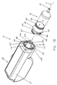
- FIGS. 1A and 1B Two embodiments of front-loading injector systems 5 and 5' of the present invention are illustrated in Figures 1A and 1B, respectively.
- a front-loading syringe and injector system is also disclosed in U.S. Patent No. 5,383,858.
- Injector systems 5 and 5' generally differ substantially only in the manner in which the syringes are mounted upon the corresponding injector. Like entities in each of systems 5 and 5' are numbered the same.
- Injector system 5 includes an injector 20 and a syringe 10.
- Injector housing 21 of injector 20 includes a reciprocating piston 22 therein which cooperates with a syringe plunger 15 to inject an injection fluid or liquid medium from the interior of syringe 10 into a patient.
- Piston 22 is extendible and retractable via a powered means contained within injection housing 21 and comprising, for example, a motor or hydraulic system, including appropriate gearing (not shown).
- injector housing 21 also preferably includes a motor controller for controlling operation of a motor and thereby controlling operation of piston 22.
- axial refers generally to an axis A around which systems 5 and 5' (including, for example, piston 22 and syringes 10 and 10') are preferably formed (although not necessarily symmetrically therearound).
- proximal refer generally to an axial direction toward the end of injector housing 21 opposite the end to which syringe 10 is mounted.
- distal refer generally to an axial direction toward a syringe tip 24 of syringe 10.
- radial refers generally to a direction normal to axis A.
- piston 22 moves axially forwardly and rearwardly through a retainer 25 comprising an opening 26 formed in a front wall 28 of injector housing 21.
- Opening 26 and syringe 10 comprise cooperating means for securely affixing syringe 10 to front wall 28.
- securing means comprise a cooperating mounting mechanism formed upon the rearward portion of syringe 10 and a cooperating retainer 25 formed upon injector front wall 28.
- opening 26 comprises a pair of opposed, axially extending slots 30 and 32.
- Slots 30 and 32 separate and define a first pair of radially inwardly projecting syringe retaining flanges 34 and 36 formed around the circumference of the opening 26.
- To the rear of first retaining flanges 34 and 36 is a first circumferential groove or channel 38, which is in communication with the axial slots 30 and 32.
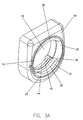
- Retaining flange 42 is shown in Figure 2A, and is substantially identical to retaining flange 40.
- Retaining flanges 34 and 40 are generally symmetrically aligned with retaining flanges 36 and 42, respectively, about axis A.
- a second circumferential channel 44 (see Figure 2A), also in communication with slots 30 and 32, is preferably formed between the rear radial sidewalls of mounting flanges 40 and 42 and a rear abutment member 46.
- Retainer 25 (including first retaining flanges 34 and 36 and second retaining flanges 40 and 42) is formed as a portion of injector front wall 28.
- Front wall 28 and retainer 25 may, for example, be machined out of aluminum or other suitable material such as plastic. Certain plastics may be preferable because of their "low friction" characteristics. In that regard, the relatively large surface of the mounting flanges and the drip flange of the present syringes may result in significant friction when installing the syringe in the injector. Any material suitable to lower frictional forces would be beneficial. Plastics such as polyacetal may offer such a benefit.
- syringe 10 comprises an elongated, generally cylindrical body 50 including a rear portion 52 which includes a first set of radially extending mounting flanges 54 and 56 and a second set of radially extending mounting flanges 58 and 60.
- a radially extending drip flange 62 is formed forwardly from first mounting flanges 54 and 56 on body 50. Drip flange 62 assists in proper axial positioning of syringe 10 with respect to front wall 28 by abutting the face of front wall 28 when syringe 10 is properly positioned.
- Drip flange 62 further substantially prevents liquid from leaking into injector housing 21. Such leakage into injector housing 21 may cause damage to injector 20. Drip flange 62 also provides structural reinforcement for syringe body 50. As illustrated, syringe 10 is formed around axis A such that its components are generally symmetrical with respect to axis A.
- first mounting flanges 54 and 56 and second mounting flanges 58 and 60 preferably includes a plurality of ribs 63.
- ribs 63 provide improved strength at reduced material cost and minimize the potential for material shrinkage that can occur during injection molding.
- first mounting flanges 54 and 56 of the syringe 10 are rotatably and closely received in first circumferential channel 38 to be retained by first retaining flanges 34 and respectively 36.
- Second mounting flanges 58 and 60 are similarly received in second channel 44 to be retained by second retaining flanges 40 and 42, respectively.
- First channel 38 is dimensioned differently from (for example, deeper and/or narrower than) second channel 44. Accordingly, first mounting flanges 54 and 56 are correspondingly narrower and/or more radially extensive than second mounting flanges 58 and 60. The dimensional differences in the mounting flanges and their respective channels substantially prevent mis-mounting or partial mounting of syringe 10 in retainer 25. For example, if the user mistakenly aligns second retaining flanges 58 and 60 with first channel 38 and attempts to rotate second mounting flanges 58 and 60 behind first retaining flanges 34 and 36, the dimensions of channel 3 8 will prevent such rotation.
- the mounting flanges and corresponding retaining flanges must provide enough area of contact to adequately retain syringe 10 without mechanical failure during injection procedures.
- One or more mounting flanges are provided around the circumference of the rear portion of syringe 10 such that the one or more flanges encompass cumulatively an arcuate length equal to at least approximately one-half of the circumference of the rear portion of syringe 10 (that is, approximately 180°). This result may be accomplished using multiple flanges as described above or using a single helical or screw-like flange (not shown). It is understood that the one or more mounting flanges may encompass cumulatively an arcuate length greater than 360° of the circumference of the rear portion of syringe 10.
- the one or more mounting flanges are positioned symmetrically around the body of syringe 10, however, to prevent unequal flange loading or torque when piston 22 engages plunger 15 to push plunger 15 forward.
- first pair of mounting flanges 54 and 56 are in general alignment with second pair of mounting flanges 58 and 60.
- the centers of the first pair of mounting flanges 54 and 56 are positioned or rotated approximately 90° from the centers of second pair of mounting flanges 58 and 60.
- the center of channel 38 is positioned or rotated approximately 90° from the center of channel 44
- the center of retaining flange 34 is positioned or rotated approximately 90° from the center of retaining flange 40, so as to accommodate the offset syringe mounting flanges 54 and 56, and 58 and 60.
- the benefits of offsetting the centers of the syringe mounting flanges are discussed below in connection with the embodiment shown in Figures 1B, 2B and 3B.
- opening 26' comprises two pairs of opposed, axially extending slots 112 and 112' and 118 and 118'.
- the centers of first pair of slots 112 and 112' are positioned or rotated approximately 90° from the centers of second pair of slots 118 and 118'.
- Slots 112 and 112' preferably separate and define at least a first pair of radially inwardly projecting syringe retaining flanges 120 and 120' formed around the circumference of the opening 26'.
- To the rear of first retaining flanges 120 and 120' is a first circumferential groove or channel 124, which is in communication with the axial slots 112 and 112'.
- retaining flanges 128 and 128' To the rear of channel 124, are a pair of second, radially inwardly projecting retaining flanges 128 and 128'. Retaining flanges 128 and 128' are generally aligned with retaining flanges 120 and 120'. Retaining flange 128 is not shown in Figure 3B, but is identical to retaining flange 128'.
- a second circumferential channel 130 (also in communication with slots 112 and 112') is formed between the rear of mounting flanges 128 and 128' and a rearward ledge 132 (see Figure 3B).
- Slots 118 and 118' are preferably formed as radially inward projecting slots in retaining flanges 120 and 120' and 128 and 128'. The depth of slots 118 and 118' is somewhat less that the radial width of retaining flanges 120 and 120'. As shown in Figure 4, slots 118 and 118' separate and frame at least third pair of radially inwardly projecting syringe retaining flanges 140 and 140' formed around the circumference of the opening 26' and 128 and 128'.
- Syringe 10' comprises a body 50' comprising a rear portion 52' which includes a first pair of radially extending mounting flanges 164 and 164' and a second pair of radially extending mounting flanges 166 and 166'.
- a radially extending drip flange 62' is formed forwardly from first mounting flanges 164 and 164' on body 50'.
- First mounting flanges 164 and 164' and second mounting flanges 166 and 166' are in general alignment.
- the structure of second mounting flanges 166 and 166' is similar to the structure of first mounting flanges 164 and 164'.
- syringe body 50' also comprises a third pair of radially extending mounting flanges 170 and 170'.
- the centers of third mounting flanges 170 and 170' are offset or rotated approximately 90° (around axis A) from the centers of first mounting flanges 164 and 164'.
- offsetting of mounting flanges as illustrated in Figure 1B, assists in evenly distributing forces over the circumference of syringe 10'.
- opening 26' receives and firmly secures syringe 10' to injector front wall 28'.
- third pair of mounting flanges 170 and 170' pass through second pair of slots 118 and 118', respectively.
- First pair of mounting flanges 164 and 164' and second pair of mounting flanges 166 and 166' pass through first pair of slots 112' and 112, respectively.
- syringe 10' is rotated clockwise relative to retainer 25' approximately 90° to firmly and releasably mount syringe 10' on injector housing 21' of injector 20'.
- the process of mounting is simple reversed.
- Second channel 44 terminates in a transverse stop 46 to abut an edge of one of second mounting flanges 58 and 60 upon full rotation of syringe 10.
- retainer 25' includes a transverse stop 146 to abut an edge of one of third mounting flanges 170 and 170' upon full rotation of syringe 10'.
- Another means of ensuring proper engagement of the syringe mounting flanges behind their corresponding retaining flanges is to provide means for providing feedback to a user once proper engagement has been effected.
- Such feedback may be audio, visual and/or tactile.
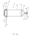
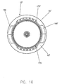
- indentations 150 and 152 may be provided on retainer 25' of injector front wall 28' to receive corresponding projections 156 and 158 formed on the rear surface of drip flange 62' (see Figure 6A). Projections 156 and 158 fall into place within indentations 150 and 152 to create an audible "click" sound when syringe 10' is properly secured.
- Visual indications that syringe 10' is properly secured may also be provided.
- a pair of indicator arrows 180 and 182 are formed on a forward surface 184 of drip flange 62'.
- indicator arrows 180 and 182 are in alignment with suitable visual indicators 186 and 188 (see Figure 4) formed on the front face of injector front wall 28.
- Projection 156 is formed at the same angular location as indicator arrow 180, while projection 158 is formed at the same angular location as indicator arrow 182. In this manner indicator arrows 180 and 182 provide a visual indication of the position of projections 156 and 158 as syringe 10' is rotated into place.
- Syringe 10' and injector 20' are further provided with cooperating data exchange mechanisms for exchanging information between syringe 10' and injector 20'.
- third mounting flanges 170 and 170' may be provided with recesses or depressions 190 and 192, respectively, formed therein to convey information concerning syringe 10' or its contents to the injector 20'. Varying the presence, type and/or location of such depressions may be used to encode information.
- a spring-actuated sensor switch 194 may be appropriately positioned to be activated by one of depressions 190 or 192 to indicate, for example, the type of syringe which has been installed, the identity of the fluid contained therein and/or the amount of fluid contained therein.
- depressions may be selectively formed in substantially any area of any mounting flange, as long as the structural integrity of the mounting flanges is not compromised.
- Similar cooperating sensor elements can also be used to ensure full engagement of syringe 10'. For example appropriate logic may be provided in a manner clear to one of skill in the art such that without full engagement, injector piston 22 will not be actuated by the injector motor and no injection will take place.
- Cooperating depressions and sensor switches may also function in a timed mode, such that the sensor switches read information from a series of depressions as they are moved past the sensor switches by the action of rotating syringe i 0' into place.
- the forward end of the syringe 10' includes a conical transition region 210 that provides a transition between main cylindrical body 50' and syringe tip 24'.
- a corner or intersection 212 is formed between cylindrical main body 50' and conical portion 210 on the syringe 10'.
- Intersection 212 is a critical zone which is likely to fail under pressure more quickly than either of the sections it joins. For this reason, intersection 212 is preferably provided with means for reinforcing structural integrity in that area.
- the wall thickness in the vicinity of intersection 212 is greater than the general wall thickness of cylindrical main body 50'.
- the wall thickness of the entire conical transition region 210 is likewise increased. Reinforcing the structural integrity of intersection 212 and conical transition region 210 enables the use of a number of materials (for example, which are chemically and biochemically compatible with the injection fluid) which would otherwise be unsuitable because of mechanical failure at high pressure.
- the wall thickness of syringe 10' may be uniformly increased throughout syringe 10' such that bending, meridianal, and circumferential (hoop) stresses are below the tensile yield stress of the syringe material used (or within the elastic region of the stress-strain curve).
- Figure 6B illustrates an embodiment of a syringe 220 in which the likelihood of failure under high internal pressure is decreased by providing a transition region 230 of a generally hemispherical shape to connect cylindrical main body 250 with syringe tip or injection region 260.
- syringe 10' is attached to a connecting tube which transports the injection fluid as known in the art to a hollow needle or the like inserted into the patient.
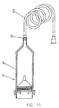
- a prefilled syringe 10' may be provided as a unit with a connecting tube 510.
- connecting tube 510 and syringe 10' are permanently affixed (for example, via an adhesive) to each other at syringe tip 24'. This joined nature allows both syringe 10' and tube 510 to be filled as a unit with an injection fluid, filling the entire volume of connecting tube 510 and a predetermined portion of elongated cylindrical main body 50'.
- Syringe tip 24' may be terminated in any one of several manners.
- syringe tip 24' terminates in a standard male luer connection 520.
- Luer connection 520 comprises an inner tubular member 522 designed to mate with a standard female luer connector (not shown) on the flexible connector tube 510 as illustrated in Figure 11.
- Syringe tip 24' also comprises a threaded outer wall 524 having an interior diameter that grips the luer connector of connector tube 510.
- Outer wall 524 comprises a double-start, right-hand threaded luer lock fitting.
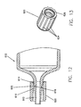
- a syringe 610 is terminated in a long, relatively thin tube section 612 which has a standard luer taper.
- Tube 612 includes an annular channel 614 extending radially inwardly from the generally cylindrical exterior surface of tube section 612.
- a generally cylindrical swivel nut 620 comprises a radially inwardly projecting engaging flange 622.
- the width of retaining flange 622 is slightly smaller than the width of channel 614.
- Swivel nut 620 is manufactured from a relatively tough and resilient material such as polycarbonate and includes a series of exterior ribs 624 to aid the user in gripping and rotating swivel nut 620. Ribs 624 extend in a direction parallel to the axis around which the syringe 610 is formed.
- swivel nut 620 is placed over tube 612 and moved rearwardly, applying sufficient force to swivel nut 620, to cause retaining flange 622 to snap over retaining flange 616 to seat in channel 614. Further rearward movement of swivel nut 620 is prevented by a second retaining flange 618. Once swivel nut 620 has been snapped into place with respect to channel 614, it may rotate freely with respect to the syringe tube 612.
- swivel nut 620 comprises a plurality of interior threads 626 for engagement of the outside flange of a female luer fitting positioned at the end of an elastomeric connector tube. Threads 626 are double start right-handed threads (for example, according to MD-70 standards). In use, swivel nut 620 is simply rotated to screw onto a connector tube which occupies the space between the exterior sidewall of tube 612 and threads 626.
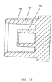
- Figure 14 is a cross-sectional illustration of a syringe tip seal 720 which is fluid-tight with respect to the injection fluid within a syringe.
- the embodiment of tip seal 720 illustrated in Figure 14 is designed for use, for example, with a syringe tip terminating in a standard luer fitting as illustrated in Figures 6A, 7A, 7B and 14.
- Tip seal 720 is fabricated from an elastomeric material that is chemically and biochemically compatible with the injection fluid.
- tip seal 720 may be fabricated from a thermoplastic elastomer or synthetic halobutyl isoprene.
- Tip seal 720 comprises an outer, generally cylindrical, seal member 722.
- Seal member 722 has a tapered inner surface which forms a seal with the outer diameter of outer wall 524 of luer connection 520.
- Tip seal 720 also comprises an inner, generally cylindrical, seal member 724.
- Inner seal member 724 comprises a tapered inner surface which forms a seal with the outer diameter of inner tubular member 522 of luer connection 520.
Abstract
Description
Claims (12)
- A syringe (10) for use with an injector (5), the syringe comprising:an elongated cylindrical main body (50); anda releasable mounting mechanism disposed on a rear portion (52) of the main body (50), whereby the syringe (10) is releasably mountable in a desired position relative to a front wall (28) of an injector housing (21), said releasable mounting mechanism comprising a first pair of mounting flanges (54, 56), the first pair of mounting flanges (54, 56) being positioned at a first axial location on the main body (50);
characterized in that the releasable mounting mechanism comprises a second pair of mounting flanges (58, 60), the second pair of the mounting flanges (58, 60) being positioned at a second axial location on the main body (50), the first pair of the mounting flanges (54,56) and the second pair of the mounting flanges (58,60) being offset from one another. - The syringe of claim 1,
wherein the mounting flanges of the first pair of mounting flanges (54, 56) are positioned symmetrically about an axis of the main body (50) and the mounting flanges of the second pair of mounting flanges (58, 60) are positioned symmetrically about the axis of the main body. - The syringe of claim 1,
wherein the mounting flanges of the first pair of mounting flanges (54, 56) are dimensioned differently from the mounting flanges of the second pair of mounting flanges (58, 60). - The syringe of claim 1,
wherein the first pair of mounting flanges (54, 56) is offset from the second pair of mounting flanges (58, 60) by 90°. - The syringe of claim 1,
comprising a third pair of mounting flanges (170, 170') connected to the rear portion of the main body, preferably offset from the first and second pairs of mounting flanges (54, 56, 58, 60). - The syringe of claim 1,
comprising an indicator (190, 192) containing information disposed on the main body, the indicator operable to be read by a sensor (194) disposed on the injector (5) when the syringe is releasably mounted on the injector. - An injector (5) for releasably supporting a syringe (10) according to claims 1 to 6 thereon, the injector comprising:characterized in that the retaining mechanism comprises:a housing (21) having a front wall (28), a powered drive member being disposed in the housing (21), adapted to engage and control a movement of a plunger (15) of the syringe (10); anda retaining mechanism (25) on the front wall of the housing (21) for cooperating with a mounting mechanism disposed on the syringe (10) to releasably mount the syringe (10) in a desired position relative to the front wall of the housing (21), the retaining mechanism operable to releasably engage the syringe (10) when the syringe (10) is inserted into and rotated within the retaining mechanism;at least two slots (30, 32) for receiving therethrough at least a first pair (54, 56) and an second pair of mounting flanges (58, 60) on the syringe when the syringe is inserted into the retaining mechanism (25); anda first pair of retaining flanges (34, 36) to releasably engage the respective first pair of mounting flanges (54, 56) on the syringe (10), when the syringe (10) is rotated within the retaining mechanism;the first pair of retaining flanges (34, 36) being positioned at a first axial location on the retaining mechanism to engage the first pair of mounting flanges (54, 56) on the syringe (10)a second pair of retaining flanges (40, 42) to releasably engage the second pair of mounting flanges (58, 60) on the syringe (10) when the syringe (10) is rotated within the retaining mechanism;
the second pair of retaining flanges (40,42) being positioned at a second axial location on the retaining mechanism to engage the second pair of mounting flanges (58, 60) on the syringe (10). - The injector of claim 7,
wherein the first pair of retaining flanges (34, 36) is in general alignment with the second pair of retaining flanges (40, 42) or the retaining mechanism (25) comprises four slots (112, 112', 118, 118') for receiving therethrough the at least first and second pairs of mounting flanges (54, 56, 58, 60) on the syringe when the syringe is inserted into the retaining mechanism, and the first pair of retaining flanges (34, 36) is radially offset from the second pair of retaining flanges (40, 42). - The injector of claim 7,
comprising a third pair of retaining flanges (140, 140') positioned at a third axial location on the retaining mechanism (25) for engaging a third pair of mounting flanges (170, 170') on the syringe. - The injector of claim 7,
comprising a sensor (194) operable to read information from an indicator (190, 192) disposed on the syringe when the syringe (10) is releasably mounted on the injector (5). - An injection system comprising:a syringe as claimed in any of claims 1 to 6 andan injector as claimed in any of claims 7 to 10.
- A method of mounting a syringe as claimed in any of claims 1 to 6 to an injector as claimed in any of claims 7 to 10,
comprising the steps of:providing a syringe (10) as claimed in any of claims 1 to 6 and an injector as claimed in any of claims 7 to 11,inserting the syringe (10) into the retaining mechanism (25) and rotating the syringe within the retaining mechanism (25).
Applications Claiming Priority (6)
| Application Number | Priority Date | Filing Date | Title |
|---|---|---|---|
| US748230 | 1996-11-12 | ||
| US08/748,230 US5944694A (en) | 1996-11-12 | 1996-11-12 | Prefillable syringes and injectors for use therewith |
| US748258 | 1996-11-12 | ||
| US08/748,258 US5873861A (en) | 1996-11-12 | 1996-11-12 | Plunger systems |
| PCT/US1997/020122 WO1998020920A2 (en) | 1996-11-12 | 1997-11-04 | Prefillable syringes, plungers and injectors for use therewith |
| US09/239,164 US6017330A (en) | 1996-11-12 | 1999-01-28 | Plunger systems |
Publications (2)
| Publication Number | Publication Date |
|---|---|
| EP0951306A2 EP0951306A2 (en) | 1999-10-27 |
| EP0951306B1 true EP0951306B1 (en) | 2005-07-20 |
Family
ID=37836969
Family Applications (1)
| Application Number | Title | Priority Date | Filing Date |
|---|---|---|---|
| EP97949362A Expired - Lifetime EP0951306B1 (en) | 1996-11-12 | 1997-11-04 | Prefillable syringes and injectors for use therewith |
Country Status (6)
| Country | Link |
|---|---|
| US (1) | US6984222B1 (en) |
| EP (1) | EP0951306B1 (en) |
| JP (2) | JP3648254B2 (en) |
| AT (1) | ATE299723T1 (en) |
| DE (1) | DE69733769T2 (en) |
| WO (1) | WO1998020920A2 (en) |
Cited By (4)
| Publication number | Priority date | Publication date | Assignee | Title |
|---|---|---|---|---|
| EP2574402A1 (en) | 2011-09-30 | 2013-04-03 | Eppendorf Ag | Nozzle having cylinder with coding and control elements |
| US9480797B1 (en) | 2015-10-28 | 2016-11-01 | Bayer Healthcare Llc | System and method for syringe plunger engagement with an injector |
| DE202017101007U1 (en) * | 2017-02-23 | 2018-05-24 | Brand Gmbh + Co Kg | Replaceable piston-cylinder unit for a dispenser, dispenser and system for receiving and dispensing fluid volumes |
| USD871606S1 (en) | 2017-11-22 | 2019-12-31 | Brand Gmbh + Co Kg | Hand operated laboratory instrument |
Families Citing this family (77)
| Publication number | Priority date | Publication date | Assignee | Title |
|---|---|---|---|---|
| US6620134B1 (en) | 1998-11-23 | 2003-09-16 | Medrad, Inc. | Syringes and injector systems with collapsible cartridges |
| JP4593714B2 (en) | 2000-02-10 | 2010-12-08 | 株式会社根本杏林堂 | Syringe outer cylinder, syringe holder, syringe piston and piston holder |
| US6652489B2 (en) | 2000-02-07 | 2003-11-25 | Medrad, Inc. | Front-loading medical injector and syringes, syringe interfaces, syringe adapters and syringe plungers for use therewith |
| US6432089B1 (en) | 2000-06-21 | 2002-08-13 | Medrad, Inc. | Medical syringe |
| AUPQ867900A0 (en) | 2000-07-10 | 2000-08-03 | Medrad, Inc. | Medical injector system |
| US8909325B2 (en) * | 2000-08-21 | 2014-12-09 | Biosensors International Group, Ltd. | Radioactive emission detector equipped with a position tracking system and utilization thereof with medical systems and in medical procedures |
| US8565860B2 (en) * | 2000-08-21 | 2013-10-22 | Biosensors International Group, Ltd. | Radioactive emission detector equipped with a position tracking system |
| US8489176B1 (en) | 2000-08-21 | 2013-07-16 | Spectrum Dynamics Llc | Radioactive emission detector equipped with a position tracking system and utilization thereof with medical systems and in medical procedures |
| FR2853837B1 (en) * | 2003-04-16 | 2006-01-13 | Crossject | DEVICE FOR CONNECTING AN ACTIVE PRINCIPLE RESERVOIR TO AN INJECTION NOZZLE IN A DEVICE FOR INJECTING SAID ACTIVE PRINCIPLE |
| US7666169B2 (en) | 2003-11-25 | 2010-02-23 | Medrad, Inc. | Syringe and syringe plungers for use with medical injectors |
| JP4460278B2 (en) * | 2003-12-17 | 2010-05-12 | 株式会社大協精工 | Seal plug for syringe and prefilled syringe |
| US8586932B2 (en) | 2004-11-09 | 2013-11-19 | Spectrum Dynamics Llc | System and method for radioactive emission measurement |
| US7968851B2 (en) | 2004-01-13 | 2011-06-28 | Spectrum Dynamics Llc | Dynamic spect camera |
| US8571881B2 (en) * | 2004-11-09 | 2013-10-29 | Spectrum Dynamics, Llc | Radiopharmaceutical dispensing, administration, and imaging |
| WO2007010534A2 (en) * | 2005-07-19 | 2007-01-25 | Spectrum Dynamics Llc | Imaging protocols |
| US9040016B2 (en) * | 2004-01-13 | 2015-05-26 | Biosensors International Group, Ltd. | Diagnostic kit and methods for radioimaging myocardial perfusion |
| US9470801B2 (en) * | 2004-01-13 | 2016-10-18 | Spectrum Dynamics Llc | Gating with anatomically varying durations |
| US7176466B2 (en) * | 2004-01-13 | 2007-02-13 | Spectrum Dynamics Llc | Multi-dimensional image reconstruction |
| US7497843B1 (en) | 2004-03-12 | 2009-03-03 | Medrad, Inc. | Syringe interfaces, syringe adapters and injector systems |
| EP1778957A4 (en) | 2004-06-01 | 2015-12-23 | Biosensors Int Group Ltd | Radioactive-emission-measurement optimization to specific body structures |
| US9316743B2 (en) | 2004-11-09 | 2016-04-19 | Biosensors International Group, Ltd. | System and method for radioactive emission measurement |
| EP1827505A4 (en) | 2004-11-09 | 2017-07-12 | Biosensors International Group, Ltd. | Radioimaging |
| US8000773B2 (en) | 2004-11-09 | 2011-08-16 | Spectrum Dynamics Llc | Radioimaging |
| US9943274B2 (en) | 2004-11-09 | 2018-04-17 | Spectrum Dynamics Medical Limited | Radioimaging using low dose isotope |
| US8615405B2 (en) | 2004-11-09 | 2013-12-24 | Biosensors International Group, Ltd. | Imaging system customization using data from radiopharmaceutical-associated data carrier |
| WO2008059489A2 (en) | 2006-11-13 | 2008-05-22 | Spectrum Dynamics Llc | Radioimaging applications of and novel formulations of teboroxime |
| US8837793B2 (en) | 2005-07-19 | 2014-09-16 | Biosensors International Group, Ltd. | Reconstruction stabilizer and active vision |
| US8926569B2 (en) | 2006-03-15 | 2015-01-06 | Bayer Medical Care Inc. | Plunger covers and plungers for use in syringes and methods of fabricating plunger covers and plungers for use in syringes |
| JPWO2007129445A1 (en) * | 2006-04-19 | 2009-09-17 | 株式会社根本杏林堂 | Syringe, chemical injection device |
| US8894974B2 (en) | 2006-05-11 | 2014-11-25 | Spectrum Dynamics Llc | Radiopharmaceuticals for diagnosis and therapy |
| CN101466614B (en) * | 2006-06-13 | 2013-05-01 | 诺信公司 | Liquid dispensing syringe |
| US7740792B2 (en) * | 2006-08-03 | 2010-06-22 | Medrad, Inc. | Methods of molding a syringe |
| US9275451B2 (en) | 2006-12-20 | 2016-03-01 | Biosensors International Group, Ltd. | Method, a system, and an apparatus for using and processing multidimensional data |
| USD1002840S1 (en) | 2007-03-14 | 2023-10-24 | Bayer Healthcare Llc | Syringe plunger |
| USD942005S1 (en) | 2007-03-14 | 2022-01-25 | Bayer Healthcare Llc | Orange syringe plunger cover |
| USD847985S1 (en) | 2007-03-14 | 2019-05-07 | Bayer Healthcare Llc | Syringe plunger cover |
| EP2155293A1 (en) * | 2007-04-11 | 2010-02-24 | Mallinckrodt Inc. | Universal syringe |
| USD588693S1 (en) | 2007-06-12 | 2009-03-17 | Nordson Corporation | Liquid dispensing syringe |
| USD738495S1 (en) | 2013-08-23 | 2015-09-08 | Nordson Corporation | Piston for a liquid dispensing syringe |
| IL194941A0 (en) * | 2007-10-29 | 2009-08-03 | Animas Corp | Drug delivery system with cartridge interlock |
| US8521253B2 (en) * | 2007-10-29 | 2013-08-27 | Spectrum Dynamics Llc | Prostate imaging |
| EP2243505B1 (en) * | 2009-04-23 | 2018-02-14 | Bayer Healthcare LLC | Syringe assemblies, methods of forming syringe assemblies |
| TWI393578B (en) * | 2009-07-07 | 2013-04-21 | Shl Group Ab | Injection device |
| DE102009034897A1 (en) * | 2009-07-27 | 2011-02-03 | Eppendorf Ag | Syringe for use with dosing device that is utilized for e.g. receiving liquid, has cylindrical piston running portion connected with outlet, and coupling piece arranged at upper end of syringe piston for insertion into piston receiver |
| US8338788B2 (en) | 2009-07-29 | 2012-12-25 | Spectrum Dynamics Llc | Method and system of optimized volumetric imaging |
| EP2482893A1 (en) * | 2009-09-30 | 2012-08-08 | Sanofi-Aventis Deutschland GmbH | Drug delivery device |
| JP5172866B2 (en) * | 2010-01-05 | 2013-03-27 | 株式会社根本杏林堂 | Syringe, cylinder holder, and chemical injection system |
| CA2799775C (en) | 2010-06-04 | 2020-03-24 | Medrad, Inc. | System and method for planning and monitoring multi-dose radiopharmaceutical usage on radiopharmaceutical injectors |
| JP5714268B2 (en) * | 2010-08-26 | 2015-05-07 | テルモ株式会社 | Prefilled syringe |
| JP5824200B2 (en) * | 2010-08-27 | 2015-11-25 | テルモ株式会社 | Prefilled syringe |
| DE102010035891A1 (en) | 2010-08-30 | 2012-03-01 | Eppendorf Ag | Syringe for use with a dosing device |
| US9498570B2 (en) | 2010-10-25 | 2016-11-22 | Bayer Healthcare Llc | Bladder syringe fluid delivery system |
| US10046106B2 (en) | 2010-10-25 | 2018-08-14 | Bayer Healthcare Llc | Bladder syringe fluid delivery system |
| WO2013043889A1 (en) * | 2011-09-21 | 2013-03-28 | Medrad, Inc. | System and assembly method for a fluid pump device for a continuous multi-fluid delivery system |
| US9291529B2 (en) | 2011-09-30 | 2016-03-22 | Eppendorf Ag | Syringe for use with a metering device |
| US9180252B2 (en) | 2012-04-20 | 2015-11-10 | Bayer Medical Care Inc. | Bellows syringe fluid delivery system |
| US9174003B2 (en) | 2012-09-28 | 2015-11-03 | Bayer Medical Care Inc. | Quick release plunger |
| US9889252B2 (en) * | 2013-06-14 | 2018-02-13 | Medtronic, Inc. | Infusion device assembly |
| JP5755700B2 (en) * | 2013-09-27 | 2015-07-29 | 株式会社根本杏林堂 | Syringe |
| JP5755703B2 (en) * | 2013-10-18 | 2015-07-29 | 株式会社根本杏林堂 | Syringe |
| SG10202002098XA (en) | 2013-10-28 | 2020-04-29 | Becton Dickinson Co | Leak-free stopper for a syringe assembly having low breakloose and sustaining forces |
| JP2017501046A (en) | 2013-11-01 | 2017-01-12 | バイエル・ヘルスケア・エルエルシーBayer HealthCare LLC | Blow molded syringe for use with injectors |
| CN106102806B (en) | 2014-03-19 | 2019-12-17 | 拜耳医药保健有限公司 | System for coupling a syringe to an injector |
| CN106104267B (en) | 2014-03-31 | 2020-11-03 | 安捷伦科技有限公司 | Seal moving with piston in high pressure pump |
| RU2709546C2 (en) * | 2014-10-28 | 2019-12-18 | БАЙЕР ХелсКер ЛЛСи | Self-oriented high-pressure casing and mechanism for high pressure casing and injector connection |
| EP3242649A4 (en) | 2015-01-09 | 2019-01-09 | Bayer Healthcare LLC | Multiple fluid delivery system with multi-use disposable set and features thereof |
| AU2016344178B2 (en) * | 2015-10-28 | 2021-08-19 | Bayer Healthcare Llc | System and method for fluid injector engagement with a pressure jacket and syringe cap |
| CN109311044A (en) * | 2016-06-30 | 2019-02-05 | 可乐丽则武齿科株式会社 | Distributor |
| US20180169326A1 (en) * | 2016-12-20 | 2018-06-21 | Liebel-Flarsheim Company Llc | Tapered front-load power injector syringe |
| ES2960350T3 (en) * | 2017-01-06 | 2024-03-04 | Bayer Healthcare Llc | Syringe plunger with dynamic seal |
| KR102281041B1 (en) | 2017-01-24 | 2021-07-26 | 바이엘 헬쓰케어 엘엘씨 | Injector systems and syringe adapters for use with them |
| DK3675935T3 (en) | 2017-08-30 | 2021-11-08 | Pirouette Medical Inc | COMPACT AUTO INJECTOR |
| WO2019071129A1 (en) | 2017-10-05 | 2019-04-11 | Pirouette Medical LLC | Protective case for an auto-injector |
| DK3758777T3 (en) | 2018-02-27 | 2023-02-27 | Bayer Healthcare Llc | INJECTION PISTON ENGAGEMENT MECHANISM |
| AU2021224642A1 (en) | 2020-02-21 | 2022-09-15 | Bayer Healthcare Llc | Fluid path connectors for medical fluid delivery |
| BR112022023295A2 (en) | 2020-06-18 | 2023-01-17 | Bayer Healthcare Llc | IN-LINE AIR BUBBLE SUSPENSION APPARATUS FOR INJECTOR FLUID PATHWAY ANGIOGRAPHY |
| JP2023538204A (en) * | 2020-06-25 | 2023-09-07 | バード・ペリフェラル・バスキュラー・インコーポレーテッド | Vial geometry for optimal mixing |
Family Cites Families (29)
| Publication number | Priority date | Publication date | Assignee | Title |
|---|---|---|---|---|
| BE756550A (en) | 1969-09-23 | 1971-03-01 | Sherwood Medical Ind Inc | REAR LOADING SYRINGE AND PROCEDURE FOR ITS FILLING |
| FR2227020B1 (en) * | 1973-04-27 | 1975-08-22 | Radiologie Cie Gle | |
| US4006736A (en) | 1974-11-27 | 1977-02-08 | Medrad, Inc. | Angiographic injector |
| GB1583157A (en) * | 1976-05-07 | 1981-01-21 | Kenova Ab | Syringes |
| US4180069A (en) * | 1976-06-01 | 1979-12-25 | The West Company | Plunger rod and piston for a syringe |
| US4490256A (en) * | 1982-11-26 | 1984-12-25 | Sartorius Gmbh | Apparatus for static membrane filtration |
| US4500310A (en) * | 1982-12-20 | 1985-02-19 | Becton, Dickinson And Company | Variable sealing pressure plunger rod assembly |
| DE3587540T3 (en) | 1984-06-06 | 1998-01-22 | Medrad Inc | Angiography syringe for use with an angiography injector. |
| US4636198A (en) | 1985-11-18 | 1987-01-13 | Mallinckrodt, Inc. | Power syringe with volume reducing adapter |
| US4628969A (en) | 1985-12-20 | 1986-12-16 | Mallinckrodt, Inc. | Method of producing prefilled sterile plastic syringes |
| US4718463A (en) | 1985-12-20 | 1988-01-12 | Mallinckrodt, Inc. | Method of producing prefilled sterile plastic syringes |
| IT1217047B (en) * | 1987-03-19 | 1990-03-14 | Cocchi Pietro | INJECTION SYRINGE, INTRAVENOUS SPECIES, MADE TO BE USED ONLY ONCE, WITHOUT POSSIBILITY OF RE-INSPIRATION. |
| US4869720A (en) | 1988-05-05 | 1989-09-26 | E-Z-Em, Inc. | Hypodermic syringe assembly |
| IT1217595B (en) | 1988-05-13 | 1990-03-30 | Molteni & C | ANTI-CONTACT DEVICE FOR INJECTION OF DENTAL ANESTHETIC SOLUTIONS CONTAINED IN CARTRIDGE |
| US4911695A (en) * | 1989-04-03 | 1990-03-27 | Coeur Laboratories, Inc. | Plunger for power-driven angiographic syringe, and syringe and power injector system utilizing same |
| US5024663A (en) | 1990-02-21 | 1991-06-18 | Alza Corporation | Self-contained suction pump |
| IT219694Z2 (en) | 1990-05-25 | 1993-04-26 | Habley Medical Technology Corp | DISPOSABLE SYRINGE, DISPOSABLE |
| US5300031A (en) * | 1991-06-07 | 1994-04-05 | Liebel-Flarsheim Company | Apparatus for injecting fluid into animals and disposable front loadable syringe therefor |
| US5246423A (en) * | 1991-11-01 | 1993-09-21 | Farkas Paul J | Remote cannula removal hypodermic syringe |
| US5256154A (en) | 1992-01-31 | 1993-10-26 | Sterling Winthrop, Inc. | Pre-filled plastic syringes and containers and method of terminal sterilization thereof |
| US5383858B1 (en) * | 1992-08-17 | 1996-10-29 | Medrad Inc | Front-loading medical injector and syringe for use therewith |
| US5373684A (en) | 1992-12-14 | 1994-12-20 | Mallinckrodt Medical, Inc. | Process and apparatus used in producing prefilled, sterile delivery devices |
| US5314415A (en) | 1993-07-21 | 1994-05-24 | Sterling Winthrop Inc. | Aspirating plunger for power injector cartridges |
| US5535746A (en) * | 1994-03-29 | 1996-07-16 | Sterling Winthrop Inc. | Prefilled syringe for use with power injector |
| US5695477A (en) | 1994-10-28 | 1997-12-09 | Sfikas; John | Needle ejector safety system |
| US5484413A (en) | 1994-11-23 | 1996-01-16 | Alexis M. Gevorgian | Disposable medical syringe with safety protection |
| US5531710A (en) | 1995-02-24 | 1996-07-02 | Courtaulds Aerospace, Inc. | Combination closure and syringe |
| US5520653A (en) * | 1995-09-01 | 1996-05-28 | Medrad, Inc. | Syringe adapter for front-loading medical injector |
| US5873861A (en) * | 1996-11-12 | 1999-02-23 | Medrad, Inc. | Plunger systems |
-
1997
- 1997-11-04 EP EP97949362A patent/EP0951306B1/en not_active Expired - Lifetime
- 1997-11-04 DE DE69733769T patent/DE69733769T2/en not_active Expired - Fee Related
- 1997-11-04 WO PCT/US1997/020122 patent/WO1998020920A2/en active IP Right Grant
- 1997-11-04 AT AT97949362T patent/ATE299723T1/en not_active IP Right Cessation
- 1997-11-04 JP JP52263898A patent/JP3648254B2/en not_active Expired - Fee Related
-
1999
- 1999-11-09 US US09/436,612 patent/US6984222B1/en not_active Expired - Fee Related
-
2000
- 2000-10-18 JP JP2000317353A patent/JP2001145697A/en active Pending
Cited By (5)
| Publication number | Priority date | Publication date | Assignee | Title |
|---|---|---|---|---|
| EP2574402A1 (en) | 2011-09-30 | 2013-04-03 | Eppendorf Ag | Nozzle having cylinder with coding and control elements |
| WO2013045013A1 (en) | 2011-09-30 | 2013-04-04 | Eppendorf Ag | Syringe with syringe cylinder with code and test elements |
| US9480797B1 (en) | 2015-10-28 | 2016-11-01 | Bayer Healthcare Llc | System and method for syringe plunger engagement with an injector |
| DE202017101007U1 (en) * | 2017-02-23 | 2018-05-24 | Brand Gmbh + Co Kg | Replaceable piston-cylinder unit for a dispenser, dispenser and system for receiving and dispensing fluid volumes |
| USD871606S1 (en) | 2017-11-22 | 2019-12-31 | Brand Gmbh + Co Kg | Hand operated laboratory instrument |
Also Published As
| Publication number | Publication date |
|---|---|
| JP3648254B2 (en) | 2005-05-18 |
| JP2001145697A (en) | 2001-05-29 |
| WO1998020920A2 (en) | 1998-05-22 |
| ATE299723T1 (en) | 2005-08-15 |
| DE69733769T2 (en) | 2006-01-12 |
| WO1998020920A3 (en) | 1998-08-27 |
| US6984222B1 (en) | 2006-01-10 |
| EP0951306A2 (en) | 1999-10-27 |
| JP2001503663A (en) | 2001-03-21 |
| DE69733769D1 (en) | 2005-08-25 |
Similar Documents
| Publication | Publication Date | Title |
|---|---|---|
| EP0951306B1 (en) | Prefillable syringes and injectors for use therewith | |
| US6017330A (en) | Plunger systems | |
| US5944694A (en) | Prefillable syringes and injectors for use therewith | |
| US6716195B2 (en) | Syringe adapters for use with an injector | |
| CN101420997B (en) | A fluid infusion system, a method of assembling such system and drug reservoir for use in the system | |
| US7497843B1 (en) | Syringe interfaces, syringe adapters and injector systems | |
| EP0847770B1 (en) | Prefilled syringe | |
| US8632521B2 (en) | Syringe assembly | |
| EP2094338B1 (en) | Syringe plunger and syringe incorporating the plunger. | |
| US8118781B2 (en) | Fluid infusion system, a method of assembling such system and drug reservoir for use in the system | |
| EP1064038B1 (en) | Syringes and plungers for use therein | |
| US6042565A (en) | Syringe, injector and injector system | |
| JP4721314B2 (en) | Plunger for syringe | |
| EP0584714A1 (en) | Medical solution delivery system |
Legal Events
| Date | Code | Title | Description |
|---|---|---|---|
| PUAI | Public reference made under article 153(3) epc to a published international application that has entered the european phase |
Free format text: ORIGINAL CODE: 0009012 |
|
| 17P | Request for examination filed |
Effective date: 19990604 |
|
| AK | Designated contracting states |
Kind code of ref document: A2 Designated state(s): AT BE CH DE FR GB IT LI LU NL SE |
|
| 17Q | First examination report despatched |
Effective date: 20011116 |
|
| GRAP | Despatch of communication of intention to grant a patent |
Free format text: ORIGINAL CODE: EPIDOSNIGR1 |
|
| RTI1 | Title (correction) |
Free format text: PREFILLABLE SYRINGES AND INJECTORS FOR USE THEREWITH |
|
| GRAS | Grant fee paid |
Free format text: ORIGINAL CODE: EPIDOSNIGR3 |
|
| GRAA | (expected) grant |
Free format text: ORIGINAL CODE: 0009210 |
|
| AK | Designated contracting states |
Kind code of ref document: B1 Designated state(s): AT BE CH DE FR GB IT LI LU NL SE |
|
| PG25 | Lapsed in a contracting state [announced via postgrant information from national office to epo] |
Ref country code: LI Free format text: LAPSE BECAUSE OF FAILURE TO SUBMIT A TRANSLATION OF THE DESCRIPTION OR TO PAY THE FEE WITHIN THE PRESCRIBED TIME-LIMIT Effective date: 20050720 Ref country code: CH Free format text: LAPSE BECAUSE OF FAILURE TO SUBMIT A TRANSLATION OF THE DESCRIPTION OR TO PAY THE FEE WITHIN THE PRESCRIBED TIME-LIMIT Effective date: 20050720 Ref country code: BE Free format text: LAPSE BECAUSE OF FAILURE TO SUBMIT A TRANSLATION OF THE DESCRIPTION OR TO PAY THE FEE WITHIN THE PRESCRIBED TIME-LIMIT Effective date: 20050720 Ref country code: AT Free format text: LAPSE BECAUSE OF FAILURE TO SUBMIT A TRANSLATION OF THE DESCRIPTION OR TO PAY THE FEE WITHIN THE PRESCRIBED TIME-LIMIT Effective date: 20050720 |
|
| REG | Reference to a national code |
Ref country code: GB Ref legal event code: FG4D |
|
| REG | Reference to a national code |
Ref country code: CH Ref legal event code: EP |
|
| REF | Corresponds to: |
Ref document number: 69733769 Country of ref document: DE Date of ref document: 20050825 Kind code of ref document: P |
|
| PG25 | Lapsed in a contracting state [announced via postgrant information from national office to epo] |
Ref country code: SE Free format text: LAPSE BECAUSE OF FAILURE TO SUBMIT A TRANSLATION OF THE DESCRIPTION OR TO PAY THE FEE WITHIN THE PRESCRIBED TIME-LIMIT Effective date: 20051020 |
|
| PG25 | Lapsed in a contracting state [announced via postgrant information from national office to epo] |
Ref country code: GB Free format text: LAPSE BECAUSE OF NON-PAYMENT OF DUE FEES Effective date: 20051104 |
|
| PG25 | Lapsed in a contracting state [announced via postgrant information from national office to epo] |
Ref country code: LU Free format text: LAPSE BECAUSE OF NON-PAYMENT OF DUE FEES Effective date: 20051130 |
|
| REG | Reference to a national code |
Ref country code: CH Ref legal event code: PL |
|
| ET | Fr: translation filed | ||
| PLBE | No opposition filed within time limit |
Free format text: ORIGINAL CODE: 0009261 |
|
| STAA | Information on the status of an ep patent application or granted ep patent |
Free format text: STATUS: NO OPPOSITION FILED WITHIN TIME LIMIT |
|
| 26N | No opposition filed |
Effective date: 20060421 |
|
| GBPC | Gb: european patent ceased through non-payment of renewal fee |
Effective date: 20051104 |
|
| PGFP | Annual fee paid to national office [announced via postgrant information from national office to epo] |
Ref country code: NL Payment date: 20071124 Year of fee payment: 11 |
|
| PGFP | Annual fee paid to national office [announced via postgrant information from national office to epo] |
Ref country code: IT Payment date: 20071128 Year of fee payment: 11 |
|
| PGFP | Annual fee paid to national office [announced via postgrant information from national office to epo] |
Ref country code: FR Payment date: 20071119 Year of fee payment: 11 |
|
| PGFP | Annual fee paid to national office [announced via postgrant information from national office to epo] |
Ref country code: DE Payment date: 20071221 Year of fee payment: 11 |
|
| PG25 | Lapsed in a contracting state [announced via postgrant information from national office to epo] |
Ref country code: NL Free format text: LAPSE BECAUSE OF NON-PAYMENT OF DUE FEES Effective date: 20090601 |
|
| NLV4 | Nl: lapsed or anulled due to non-payment of the annual fee |
Effective date: 20090601 |
|
| PG25 | Lapsed in a contracting state [announced via postgrant information from national office to epo] |
Ref country code: IT Free format text: LAPSE BECAUSE OF NON-PAYMENT OF DUE FEES Effective date: 20081104 |
|
| REG | Reference to a national code |
Ref country code: FR Ref legal event code: ST Effective date: 20090731 |
|
| PG25 | Lapsed in a contracting state [announced via postgrant information from national office to epo] |
Ref country code: DE Free format text: LAPSE BECAUSE OF NON-PAYMENT OF DUE FEES Effective date: 20090603 |
|
| PG25 | Lapsed in a contracting state [announced via postgrant information from national office to epo] |
Ref country code: FR Free format text: LAPSE BECAUSE OF NON-PAYMENT OF DUE FEES Effective date: 20081130 |