EP0951920A2 - Electrode cable for attachement to a vessel wall - Google Patents
Electrode cable for attachement to a vessel wall Download PDFInfo
- Publication number
- EP0951920A2 EP0951920A2 EP99250128A EP99250128A EP0951920A2 EP 0951920 A2 EP0951920 A2 EP 0951920A2 EP 99250128 A EP99250128 A EP 99250128A EP 99250128 A EP99250128 A EP 99250128A EP 0951920 A2 EP0951920 A2 EP 0951920A2
- Authority
- EP
- European Patent Office
- Prior art keywords
- electrode
- vessel
- base body
- line according
- electrode line
- Prior art date
- Legal status (The legal status is an assumption and is not a legal conclusion. Google has not performed a legal analysis and makes no representation as to the accuracy of the status listed.)
- Granted
Links
Images


Classifications
-
- A—HUMAN NECESSITIES
- A61—MEDICAL OR VETERINARY SCIENCE; HYGIENE
- A61N—ELECTROTHERAPY; MAGNETOTHERAPY; RADIATION THERAPY; ULTRASOUND THERAPY
- A61N1/00—Electrotherapy; Circuits therefor
- A61N1/02—Details
- A61N1/04—Electrodes
- A61N1/05—Electrodes for implantation or insertion into the body, e.g. heart electrode
- A61N1/056—Transvascular endocardial electrode systems
- A61N1/057—Anchoring means; Means for fixing the head inside the heart
-
- A—HUMAN NECESSITIES
- A61—MEDICAL OR VETERINARY SCIENCE; HYGIENE
- A61N—ELECTROTHERAPY; MAGNETOTHERAPY; RADIATION THERAPY; ULTRASOUND THERAPY
- A61N1/00—Electrotherapy; Circuits therefor
- A61N1/02—Details
- A61N1/04—Electrodes
- A61N1/05—Electrodes for implantation or insertion into the body, e.g. heart electrode
- A61N1/056—Transvascular endocardial electrode systems
- A61N2001/0585—Coronary sinus electrodes
Landscapes
- Health & Medical Sciences (AREA)
- Cardiology (AREA)
- Heart & Thoracic Surgery (AREA)
- Vascular Medicine (AREA)
- Engineering & Computer Science (AREA)
- Biomedical Technology (AREA)
- Nuclear Medicine, Radiotherapy & Molecular Imaging (AREA)
- Radiology & Medical Imaging (AREA)
- Life Sciences & Earth Sciences (AREA)
- Animal Behavior & Ethology (AREA)
- General Health & Medical Sciences (AREA)
- Public Health (AREA)
- Veterinary Medicine (AREA)
- Electrotherapy Devices (AREA)
Abstract
Description
Die Erfindung betrifft eine Gefäßelektrodenleitung für einen Herzschrittmacher.The invention relates to a vascular electrode line for a pacemaker.
Bei der Therapie verschiedener chronischer Herzrhythmusstörungen sind seit langem implantierte Herzschrittmacher in Verbindung mit auf einem intrakardialen Elektrodenkatheter angeordneten und an der Herzinnenwand positionierten Stimulationselektroden in Gebrauch, über die das reizbare Herzgewebe erregt und dadurch ein Defekt des körpereigenen kardialen Reizbildungs- und -leitungssystems ausgeglichen wird.In the treatment of various chronic cardiac arrhythmias have long been implanted pacemakers in conjunction with on an intracardiac Electrode catheters arranged and positioned on the inner wall of the heart Stimulation electrodes in use, which excite the irritable heart tissue and thereby a defect in the body's own cardiac stimulus generation and conduction system is balanced.
Die Ausführung der Elektrodenleitungen ist immer weiter vervollkommnet worden. Mit dem Ziel einer langfristigen Gewährleistung eines guten Kontaktes zwischen der oder den Stimulationselektrode(n) und dem Herzgewebe im Interesse einer zugleich energiesparenden und sicheren Stimulation sind zahlreiche technische Lösungen zur Verankerung der Elektrodenleitungen an der Herzwand - sowohl in der Herzkammer (Ventrikel) als auch im Vorhof (Atrium) - gefunden worden und tatsächlich wesentliche praktische Verbesserungen gelungen. The execution of the electrode lines has been continually improved. With the aim of ensuring long-term good contact between the or the stimulation electrode (s) and the heart tissue in the interest of one at the same time Energy-saving and safe stimulation are numerous technical solutions for Anchoring the electrode leads to the heart wall - both in the heart chamber (Ventricle) as well as in the atrium (atrium) - have been found and actually substantial practical improvements succeeded.
Es sind auch Elektrodenleitungen - speziell für implantierbare Defibrillatoren - vorgeschlagen worden, die in große herznahe Gefäße eingeführt werden und die Defibrillationsenergie an die Gefäßwand abgeben.There are also electrode leads - especially for implantable defibrillators - have been proposed which are inserted into large vessels near the heart and which Deliver defibrillation energy to the vessel wall.
Die EP 0 601 338 A1 beschreibt ein solches Elektrodensystem für einen implantierten Defibrillator, das mindestens zwei - ohne besondere Verankerung allein aufgrund ihrer Größe ortsfest gehaltene - intravaskular plazierte Spulenelektroden (spiralförmige Elektroden) umfaßt. Eine dieser großflächigen Defibrillationselektroden kann speziell in der Vena cava superior angeordnet sein, eine weitere im Koronarsinus.EP 0 601 338 A1 describes such an electrode system for an implanted Defibrillator that has at least two - without special anchoring alone Due to their size, they are held in place - intravascularly placed coil electrodes (spiral electrodes). One of these large-area defibrillation electrodes can be located specifically in the superior vena cava, another in the coronary sinus.
Die US 5,571,159 beschreibt einen temporär einsetzbaren Katheter zur atrialen Defibrillation, der neben einem ersten, im Atrium positionierten spiraligen Elektrodenabschnitt einen zweiten, in der Pulmonararterie plazierten Elektrodenabschnitt und am distalen Ende einen aufblasbaren Ballon zur Positionierung der Elektroden aufweist.US 5,571,159 describes a temporary catheter for atrial use Defibrillation, the next to a first spiral positioned in the atrium Electrode section a second electrode section placed in the pulmonary artery and an inflatable balloon at the distal end for positioning the Electrodes.
Die EP 0 566 652 B2 beschreibt eine in Art eines Stents geformte und mittels eines Dilatations-Ballons aufweitbare Elektrodenkonfiguration zum Einsatz als Defibrillationselektrode in einem Blutgefäß, speziell im Koronarsinus.EP 0 566 652 B2 describes a shaped like a stent and by means of a Dilatation balloons expandable electrode configuration for use as a defibrillation electrode in a blood vessel, especially in the coronary sinus.
Für bestimmte Anwendungen - etwa die sogenannte biatriale oder Multisite- Stimulation - kann auch eine Plazierung von Schrittmacher-Stimulations- oder Abfühlelektroden in einem herznahen Gefäß, speziell im Koronarsinus, zweckmäßig sein, weil eine Elektrodenimplantation speziell im linken Atrium problematisch ist. Hierfür eignen sich die bekannten großflächigen Defibrillationselektroden grundsätzlich nicht.For certain applications - such as the so-called biatrial or multisite Pacing - can also be a pacemaker or pacemaker Sensing electrodes in a vessel close to the heart, especially in the coronary sinus, are useful because electrode implantation is particularly problematic in the left atrium. The known large-area defibrillation electrodes are basically suitable for this Not.
Der Erfindung liegt daher die Aufgabe zugrunde, eine für die Schrittmacher-stimulation bzw. das Abfühlen von Herzaktionen geeignete Gefäßelektrodenleitung der eingangs genannten Gattung anzugeben.The invention is therefore based on the object of pacemaker stimulation or sensing cardiac electrode conduction to specify the genus mentioned at the beginning.
Diese Aufgabe wird durch eine Gefäßelektrodenleitung mit den Merkmalen des Anspruchs 1 gelöst.This task is accomplished by a vascular electrode line with the characteristics of Claim 1 solved.
Die Erfindung schließt den Gedanken ein, eine Gefäßelektrodenleitung mit mindestens einer kleinflächigen Elektrode und an die Gefäßkonfiguration angepaßten Fixierungsmitteln zu realisieren, mit der in effizienter Weise und mit exakter The invention includes the idea of including a vascular electrode line at least one small-area electrode and adapted to the vessel configuration Realize fixation means with which in an efficient manner and with more exact
Positionierung Stimulationsimpulse auf die Gefäßwandung übertragen bzw. Herzaktionspotentiale abgegriffen werden können.Positioning transmit stimulation impulses to the vessel wall or Heart action potentials can be tapped.
Zur Ausführung dieses Gedankens umfaßt die vorgeschlagene Elektrodenleitung eine Elektrode bzw. Elektroden, deren effektive Durchmesser (wie von intrakardialen Elektrdoenanordnungen bekannt) annähernd gleich dem Durchmesser des Grundkörpers ist und nicht als Elektrode wirkende (insbesondere eine isolierende Oberfläche aufweisende) Fixierungsmittel zur ortsfesten Positionierung der Elektrode bzw. Elektroden bezüglich der Gefäßwandung.To implement this idea, the proposed electrode line includes an electrode or electrodes whose effective diameter (as from intracardiac Electrode arrangements known) approximately equal to the diameter of the Base body is and not acting as an electrode (in particular an insulating Fixing means with surface for the fixed positioning of the electrode or electrodes with respect to the vessel wall.
Die Fixierungsmittel der vorgeschlagenen Gefäßelektrodenleitung unterscheiden sich von denen intrakardial zu verankernder Elektrodenleitungen in der Gestalt, zumindest aber den Abmessungen, da sie nicht einer Fixierung durch Verankerung in relativ dickem Muskelgewebe oder dem Trabekelwerk des Ventrikels dienen. Vielmehr beruht die Fixierung entweder auf einer elastischen Verspannung gegen die Gefäßwand oder alternativ auf dem Eingriff in die Wandung bzw. Verzweigungen eines Nebengefäßes.The fixation means of the proposed vascular electrode line differ of which electrode leads to be anchored intracardially in the form but at least the dimensions, as they are not fixed by anchoring serve in relatively thick muscle tissue or the trabecular structure of the ventricle. Rather, the fixation is based either on elastic tension the vessel wall or alternatively on the engagement in the wall or branches a secondary vessel.
Entsprechend der ersten Alternative umfassen die Fixierungsmittel einen im wesentlichen koplanar sinusförmig oder auf der Mantelfläche eines Zylinders mit elliptischer Grundfläche wendelförmig elastisch vorgeprägten Abschnitt des Grundkörpers. Dieser hat (im entspannten Zustand) bevorzugt eine laterale Erstreckung vom Zwei- bis Fünffachen des Durchmesssers des Grundkörpers und eine auf die Elastizität der Gefäßwand abgestimmte Elastitizät. Er hat eine Längserstreckung, die im Interesse einer sicheren Positionierung bei Vermeidung hoher lokaler Belastung der Gefäßwand zweckmäßigerweise mehr als eine Sinusperiode oder mehr als einen vollständigen Zylindermantel-Umlauf umfaßt.According to the first alternative, the fixing means comprise an im essentially coplanar sinusoidal or on the lateral surface of a cylinder with elliptical base area helically elastic pre-embossed section of the Basic body. In the relaxed state, this preferably has a lateral one Extension of two to five times the diameter of the base body and an elasticity tailored to the elasticity of the vessel wall. He has one Longitudinal extension in the interest of safe positioning with avoidance high local stress on the vessel wall expediently more than one Sine period or more than one complete cylinder jacket revolution.
In der Ausführung der zweiten Alternative sind am distalen Ende des Grundkörpers flexible Fixierungsmittel zur Fixierung im besagten Seitengefäß (speziell des Koronarsinus) mit auf dessen Durchmesser abgestimmter lateraler Erstreckung angebracht, und der Grundkörper ist in diesem Bereich hochgradig biegsam ausgeführt, um ein leichtes Abwinkeln in das Seitengefäß hinein zu ermöglichen.In the execution of the second alternative are at the distal end of the body flexible fixation means for fixation in said side vessel (especially the Coronary sinus) with a lateral extension matched to its diameter attached, and the body is highly flexible in this area designed to allow easy angling into the side vessel.
Als derartiges Fixierungsmittel ist bevorzugt ein das distale Ende des Grundkörpers umgebender Kunststoff-Schneckengewindeabschnitt mit einer oder mehreren Windungen, insbesondere aus dem Material des Grundkörpers, vorgesehen, mit dem die Elektrodenleitung in einem kleineren venösen Seitengefäß des Koronarsinus aktiv fixiert werden kann. Dieses wird durch das " Einschrauben " der Elektrodenleitung zwar weitgehend verschlossen, die damit bewirkte Stauung ist bei einem Seitengefäß aber tolerierbar.The distal end of the base body is preferably a fixing means of this type surrounding plastic screw thread section with one or more Windings, in particular made of the material of the base body, provided with the the electrode lead in a smaller venous side vessel of the coronary sinus can be actively fixed. This is done by "screwing in" the electrode lead Although largely closed, the congestion caused by one Side vessel but tolerable.
Alternativ zur letztgenannten Ausführung kann der Grundkörper eine Mehrzahl von gegenüber seiner Längsachse zum proximalen Ende hin federnd geneigten Kunststoff-Finnen tragen, mit denen die Gefäßelektrodenleitung in Verzweigungen des herznahen Gefäßsystems passiv verankert werden kann. Die Abmessungen der Finnen bzw. "Flossen" sind in Abstimmung auf die andere Körperumgebung größer als bei ähnlichen Anordnungen, die im Trabekelwerk des Ventrikels verankert werden.As an alternative to the latter embodiment, the base body can have a plurality of with respect to its longitudinal axis towards the proximal end resiliently inclined Wear plastic fins with which the vascular electrode lead is branched of the cardiac system close to the heart can be passively anchored. The dimensions of the Fins or "fins" are larger in coordination with the other body environment than with similar arrangements anchored in the trabecular meshwork of the ventricle become.
Weiterhin stellen eine während der Einführung streckbare elastische Wendel oder ein in Art eines Stents nach der Einführung aufweitbarer rohr- oder ringförmiger Hohlkörper mit an den Gefäßdurchmesser angepaßten Endabmessungen geeignete Fixierungsmittel dar.Furthermore, an elastic coil or stretchable during insertion a tubular or ring-shaped expandable in the manner of a stent after insertion Suitable hollow bodies with end dimensions adapted to the vessel diameter Fixative.
Hierbei ist es von Vorteil, wenn die elektrisch aktive Oberfläche relativ klein bleibt. Das kann entweder durch mindestens teilweise Isolierung der Oberfläche oder mindestens teilweise Ausführung aus einem nichtleitenden Material oder auch durch minimale Dimensionierung des gesamten Fixierungselementes erreicht werden. Die Elektroden können so auf der Leitung plaziert werden, daß (bei einer unipolaren Leitung) die Elektrode oder (bei einer bi- oder multipolaren Leitung) die distalste von mehreren Elektroden einen Abstand zwischen 30 und 80 mm vom distalen Ende des Grundkörpers hat, so daß in Verbindung mit einem auf diesen Abstand abgestimmten Krümmungsverlauf des Grundkörpers im implantierten Zustand eine stabile Ausrichtung der Elektrode(n) relativ zur Gefäßwand gewährleistet ist. Entsprechend beträgt bei einer bipolaren Leitung der Abstand der Elektroden zwischen 30 und 80 mm. Auch der Einsatz einer Spitzenelektrode ist - allein oder in Kombination mit einer Ringelektrode - möglich.It is advantageous here if the electrically active surface remains relatively small. This can be done either by at least partially isolating the surface or at least partially made of a non-conductive material or by minimal dimensioning of the entire fixation element can be achieved. The electrodes can be placed on the line in such a way that (with a unipolar Lead) the electrode or (for a bi- or multipolar lead) the most distal of several electrodes a distance between 30 and 80 mm from the distal end of the Has basic body, so that in connection with a tuned to this distance Curvature of the base body in the implanted state is stable Alignment of the electrode (s) relative to the vessel wall is ensured. Corresponding For a bipolar lead, the distance between the electrodes is between 30 and 80 mm. The use of a tip electrode is also - alone or in combination with a ring electrode - possible.
Die erste und/oder zweite Stimulationselektrode weist bevorzugt eine geometrische Oberfläche im Bereich zwischen 10 und ca. 25 mm2 und insbesondere eine fraktale Oberflächen-Mikrostruktur zur Vergrößerung der elektrisch wirksamen Oberfläche um einen Faktor von mindestens 102 auf.The first and / or second stimulation electrode preferably has a geometric surface in the range between 10 and approximately 25 mm 2 and in particular a fractal surface microstructure for enlarging the electrically active surface by a factor of at least 10 2 .
Weiterhin ist bevorzugt eine das Einwachsen positiv beeinflussende Wirkstoffbeschichtung vorgesehen, etwa eine Kollagen- oder Fibronectin-Beschichtung. Also preferred is an active ingredient coating which has a positive influence on ingrowth provided, such as a collagen or fibronectin coating.
Besonders vorteilhafte Ausführungen ergeben sich aus der Erkenntnis, daß in der Praxis der für eine Fixierung der Leitung am besten geeignete Ort nicht in fester Positionsbeziehung zu dem für die Stimulation am besten geeigneten Ort des Gefäßes steht. Daraus resultiert die Überlegung, den elektrisch aktiven Teil der Anordnung gegenüber dem zur mechanischen Fixierung vorgesehenen Teil in gewissen Grenzen frei positionierbar zu machen. Dies ist in zweckmäßiger Weise durch das Vorsehen separater Träger für die Elektroden einerseits und das oder die Fixierungsmittel andererseits zu realisieren, die während der Plazierung der Elektrodenleitung relativ zueinander bewegbar sind und deren Stellung nach Ermittlung der optimalen Position für das Fixierungsmittel und die Elektroden festgelegt wird.Particularly advantageous designs result from the knowledge that in the Practice the most suitable place for a fixation of the line not in fixed Positional relationship to the most suitable location for the stimulation Vessel stands. This results in the consideration of the electrically active part of the Arrangement in relation to the part intended for mechanical fixation in make certain positions freely positionable. This is convenient by providing separate supports for the electrodes on the one hand and that or the On the other hand to realize fixation means, which during the placement of the Electrode line are movable relative to each other and their position Determination of the optimal position for the fixative and the electrodes is set.
Das Festlegen kann beispielsweise durch Crimpen oder durch eine spannzangenähnliche Einrichtung im Bereich des Steckers geschehen.The setting can, for example, by crimping or by a collet-like Set up in the area of the connector.
Vorteilhafte Weiterbildungen der Erfindung sind im übrigen in den Unteransprüchen gekennzeichnet bzw. werden nachstehend zusammen mit der Beschreibung der bevorzugten Ausführung der Erfindung anhand der Figuren näher dargestellt. Es zeigen:
- Figuren 1, 1a, 1b schematische Darstellungen einer Gefäßelektrodenleitung gemäß einer ersten Ausführungsform der Erfindung in Seitenansicht bzw. Vorderansichten des distalen Endes in zwei Abwandlungen,
- Figur 2 eine schematische Darstellung einer Gefäßelektrodenleitung gemäß einer zweiten Ausführungsform in Seitenansicht,
- Figur 3 eine schematische Darstellung einer Gefäßelektrodenleitung gemäß einer dritten Ausführungsform,
- Figur 4 eine schematische Darstellung einer Gefäßelektrodenleitung gemäß einer vierten Ausführungsform,
- Figuren 5, 5a eine schematische Darstellung einer Gefäßelektrodenleitung gemäß einer fünften Ausführungsform,
- Figuren 6, 6a eine schematische Darstellung einer Gefäßelektrodenleitung gemäß einer sechsten Ausführungsform,
- Figur 7 eine schematische Darstellung einer Gefäßelektrodenleitung gemäß einer siebenten Ausführungsform und
- Figuren 8a bis 8d schematische Darstellungen verschiedener Ausführungen eines Details bei den Gefäßelektrodenleitungen der in Fig. 5 bis 7 gezeigten Art.
- 1, 1a, 1b schematic representations of a vascular electrode line according to a first embodiment of the invention in side view or front views of the distal end in two modifications,
- FIG. 2 shows a schematic illustration of a vascular electrode line according to a second embodiment in side view,
- FIG. 3 shows a schematic illustration of a vascular electrode line according to a third embodiment,
- FIG. 4 shows a schematic illustration of a vascular electrode line according to a fourth embodiment,
- 5, 5a show a schematic representation of a vascular electrode line according to a fifth embodiment,
- 6, 6a a schematic illustration of a vascular electrode line according to a sixth embodiment,
- Figure 7 is a schematic representation of a vascular electrode line according to a seventh embodiment and
- FIGS. 8a to 8d are schematic representations of various designs of a detail in the vascular electrode lines of the type shown in FIGS. 5 to 7.
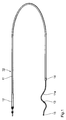
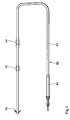
Fig. 1, 1a und 1b zeigen eine Gefäßelektrodenleitung 10 mit einem die (nicht
gezeigten) Elektrodenzuleitungen aufnehmenden Grundkörper 11, einem Stecker 12
und zwei Ringelektroden 13, 14. Die vordere (distalere) Ringelektrode 13 hat einen
Abstand von ca. 25 mm vom distalen Ende der Leitung, an dem ein Ptlr-Röntgenmarkerabschnitt
15 vorgesehen ist, einen Durchmesser von 2 mm und eine Länge
von 2 mm. Die hintere (proximalere) Elektrode 14 hat von der vorderen Elektrode
einen Abstand zwischen 60 und 80 mm, einen Durchmesser von 2,4 mm und eine
Länge von 3 mm.1, 1a and 1b show a
Der distale Abschnitt 11a des Grundkörpers 1 1 weist eine mittels einer Seele aus
getempertem Stahl MP35N elastisch vorgeprägte, annähernd sinus- oder S-förmige
Krümmung und zugleich eine ellipsenförmige Wendelung auf, die in Fig 1a bzw. 1b
(in zwei Varianten des Verlaufes) zu erkennen ist. Die maximale laterale Erstreckung
der Elektrodenleitung ist in diesem Bereich in Abstimmung auf den Durchmesser des
als Einsatzort vorgesehenen Gefäßes vorbestimmt und beträgt für eine Koronarsinus-Elektrodenleitung
etwa 8 mm. Die Elastizität der Leitung ist durch geeignete
Wahl der Stärke und der Materialbehandlungsbedingungen der Stahlseele derart
vorbestimmt, daß sie durch den bei der Implantation eingesetzten Führungsdraht
ohne weiteres gestreckt werden kann und nach Entfernen des Führungsdrahtes in
der dargestellten Konfiguration einen zur Positionsfixierung hinreichenden Druck auf
die Gefäßwand ausübt, ohne diese wesentlich aufzuweiten.The
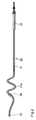
Fig. 2 zeigt eine weitere Gefäßelektrodenleitung 20 mit einem Grundkörper 21,
einem Stecker 22 und einer Spitzenelektrode 23 sowie einer Ringelektrode 24, die
einen Abstand von ca. 30 mm voneinander haben. Auch hier ist dem distalen
Bereich 21a der Leitung 20, der sich über eine Länge von etwa 60 mm erstreckt,
eine sinusartige Krümmung und Wendelung eingeprägt, die nahe der Spitzenelektrode
einen sanften Verlauf zeigt und erst nahe der Position der Ringelektrode
höhere Gradienten annimmt. Der gekrümmte Abschnitt umfaßt hier annähernd zwei
Sinus-Perioden und Umläufe auf dem Mantel des die Wendelung beschreibenden
elliptischen Zylinders.2 shows a further
Eine im distalen Endabschnitt gestreckte Gefäßelektrodenleitung 30 mit einem
Grundkörpers 31 und einem Stecker 32 ist in Fig. 3 dargestellt. Die Leitung 30
weist zwei Ringelektroden 33 und 34 mit Durchmessern von 2 bzw. 2,4 mm und
Längen von 2 bzw. 3 mm auf. Die näher zum distalen Leitungsende gelegene
Elektrode 43 hat zum Ende einen Abstand von 75 mm, und der Abstand zwischen
beiden Elektroden beträgt 25 mm.A
Am distalen Ende ist an den Grundkörper 31 eine aus einem Silikonpolymeren
gebildete Schneckenwendel 35 von ca. 5 mm Länge mit zwei Windungen angefügt,
die den Gesamtdurchmesser der Leitung in diesem Bereich auf ca. 3 mm vergrößert.
Die Leitung wird bei der Implantation so geführt, daß das "Gewinde" an der Spitze
in die Einmündung eines Seitengefäßes gelangt, und anschließend wird sie dort
vermittels entsprechender Drehung des Führungsdrahtes eingeschraubt. Aufgrund
der ausgeprägten Biegungselastizität der Leitung verspannt sich deren Endbereich
nach der Fixierung bogenförmig von der Gefäßmündung des Seitengefäßes aus zur
gegenüberliegenden Wandung des Hauptgefäßes (z.B. Koronarsinus), so daß die
Elektroden mit dessen Wandung in Kontakt stehen, ohne daß ein zu großer lokaler
Druck auf die Gefäßwand ausgeübt wird.At the distal end of the
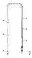
Eine weitere Gefäßelektrodenleitung 40 mit vom Stecker 42 bis zum distalen Ende
durchgehend gestrecktem Verlauf des Grundkörpers 41 ist in Fig. 4 dargestellt. Die
Leitung 30 weist zwei Ringelektroden 43 und 44 mit Durchmessern von 2 bzw. 2,4
mm und einer Länge von jeweils 3 mm auf. Die näher zum distalen Leitungsende
gelegene Elektrode 43 hat zum Ende einen Abstand von 50 bis 60 mm, und der
Abstand zwischen beiden Elektroden beträgt 30 bis 40 mm.Another
Am distalen Ende sind an den Grundkörper Kunststoff-Finnen bzw. -Widerhaken 45
(die bevorzugt aus dem Material des Grundkörpers, d.h. in der Regel einem
Silikonpolymeren, gebildet sind) angeformt. Die Finnen 45 sind ausgeprägt
spitzwinklig und länger als ähnliche Verankerungselemente von intrakardialen
Elektrodenleitungen, jedoch biegsam ausgeführt. Die Leitung wird mittels des
Führungsdrahtes so geführt, daß die Finnen sich in einer Gefäßverzweigung oder
der Einmündung eines Seitengefäßes verhaken und so die Elektroden in geeigneter
Lage relativ zur Wandung des für die Anbringung vorgesehenen Gefäßes, speziell
des Koronarsinus, fixieren. Plastic fins or
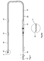
Fig. 5a und 5a zeigen schematisch eine weitere Gefäßelektrodenleitung 50.5a and 5a schematically show a further
Hinsichtlich der Anordnung des Grundkörpers 51, des Steckers 52 und der
Elektroden 53, 54 gleicht diese den Anordnungen nach Fig. 3 oder 4, so daß
insoweit die Beschreibung nicht wiederholt wird. Jedoch ist hier der Grundkörper
51 so ausgeführt, daß er in axialverschieblicher Weise einen gegenüber dem
Grundkörper um einige Zentimeter längeren Fixierungselement-Trägerkörper 56
aufnimmt. An dessen distalem Ende ist eine hochelastische Wendel 55 aus
biokompatiblem Metall (etwa einer NiTi-Legierung) oder Kunststoff befestigt. Auch
der Trägerkörper 56 ist hohl, so daß in ihn ein Führungsdraht 58 einführbar ist, an
dessen proximalem Ende ein zweiteiliger Handgriff 57 angebracht ist.With regard to the arrangement of the
Der Führungsdraht 58 greift in ein entsprechend ausgebildetes Ende der elastischen
Wendel 55 ein, so daß diese durch Vorschieben des Führungsdrahtes 58 gegenüber
dem Fixierungselement-Trägerkörper 56 gestreckt werden kann, wie in der
Darstellung des Ausschnitts A aus Fig. 5 in Fig 5a zu erkennen ist.The
Dies erlaubt ein leichtes Einführen der Leitung 50 mit gestreckter Wendel 55. Nach
Erreichen des gewünschten Plazierungsortes wird beim Zurückziehen des
Führungsdrahtes die Wendel entlastet und nimmt ihre vorgeprägte Form an, in der
sie einen derart an die Innenabmwessungen des Gefäßes angepaßten Durchmesserhat,
daß sie an dessen Wandung unter leichtem Druck anliegt.This allows easy insertion of the
Durch Axialverschiebung des Grundkörpers 51 auf dem somit fixierten Fixierungselement-Trägerkörper
56 mittels des zweiten Teils des Handgriffs 57 kann
anschließend die optimale Positionierung der Elektroden 53, 54 im einem relativ
großen Einstellbereich vorgenommen werden. Nach erfolgter Positionierung wird
schließlich (auf weiter unten genauer beschriebene Weise) die Stellung des
Grundkörpers relativ zum Fixierungselement-Trägerkörper festgelegt und das über
den Steckerstift 52 ggfs. noch überstehende proximale Ende des Trägerkörpers 56
abgetrennt, womit die Implantation der Leitung 50 beendet ist.By axially displacing the
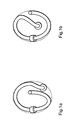
Fig. 6 und 6a zeigen eine in Aufbau und Funktion der oben beschriebenen Leitung
nach Fig. 5 ähnliche Gefäßelektrodenleitung 60, bei der aber anstelle einer
elastischen Wendel ein nach der Einführung in Art eines Stents aufweitbares
rohrförmiges Fixierungselement 65 aus einer Ti-Legierung vorgesehen ist. Der
Handgriff 67 dient hier nur zur Verschiebung des Fixierungselement-Trägerkörpers
66 relativ zum Grundkörper 61. Er weist zusätzlich einen Luer-Lock-Anschluß 67a
zur Verbindung mit einer (nicht gezeigten) Fluidquelle auf, die zur Aufweitung des
Fixierungselementes 65 durch Ballon-Dilatation in an sich bekannter Weise benötigt
wird. Den aufgeweiteten Zustand zeigt die Darstellung des Ausschnitts A in Fig. 6a.6 and 6a show a structure and function of the line described above
5 similar
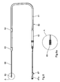
Fig. 7 zeigt eine der Ausführung nach Fig. 3 ähnliche Gefäßelektrodenleitung 70,
bei der aber - wie bei den Anordnungen gemäß Fig. 5 und 6 - für die schneckenartige
Einschraubwendel 75 ein im Leitungs-Grundkörper 71 aufgenommener und
diesem gegenüber axial verschieblicher Trägerkörper 76 vorgesehen ist, an dessen
proximalem Ende ein Handgriff 77 zur Verschiebung des Trägerkörpers 76 und zum
Einschrauben der Schneckenwendel 76 angebracht ist.FIG. 7 shows a
Fig. 8a bis 8d zeigen in Prinzipskizzen verschiedene Ausführungen eines wesentlichen
Details bei Gefäßelektrodenleitungen der in Fig. 5 bis 7 gezeigten Art, nämlich
der Mittel zum Festlegen der Stellung des Fixierungsmittel-Trägerkörpers relativ zum
Grundkörper. In Fig. 8a ist zu diesem Zweck im Stecker 52' eine auf den
Fixierungsmittel-Trägerkörper 56 angreifende Madenschraube 52a vorgesehen, in
Fig. 8b ist der innere Steckerstift 52.1" eines modifizierten Steckers 52" aus zwei
in Art einer Spannzange zusammenwirkenden Teilen 52.1a" und 52.1b" gebildet,
wie am besten in der Querschnittsdarstellung des Ausschnitts A aus Fig. 8b in Fig.
8c zu erkennen ist.8a to 8d show in principle sketches different versions of an essential
Details for vascular electrode lines of the type shown in FIGS. 5 to 7, namely
the means for determining the position of the fixative carrier body relative to
Basic body. In Fig. 8a is for this purpose in the connector 52 'on
Fixing means
Bei der Ausführung nach Fig. 8d schließlich ist der Fixierungselement-Trägerkörper
52"' distal vom Stecker 52"' mit einem - von verzweigten Elektrodenleitungen an
sich bekannten - Abzweigelement 59"' versehen, in dem der Fixierungsmittel-Trägerkörper
56"' (und mit diesem der Führungsdraht 58) seitlich in den Grundkörper
51"' eingefädelt ist. Das Festlegen nach erfolgter Positionierung erfolgt hier
mittels einer Ligatur.Finally, in the embodiment according to FIG. 8d, the fixing
Die Erfindung beschränkt sich in ihrer Ausführung nicht auf die vorstehend angegebenen bevorzugten Ausführungsbeispiele. Vielmehr ist eine Anzahl von Varianten möglich, welche von der dargestellten Lösung auch in anders gearteter Ausführung Gebrauch machen.The embodiment of the invention is not limited to the above specified preferred embodiments. Rather is a number of Variants possible, which of the solution shown also in a different kind Use execution.
So können die in Fig. 1 und 2 gezeigten Ausführungen dahingehend modifiziert sein, daß das distale Ende keine Wendelung, sondern eine im wesentlichen koplanare oder in zwei zueinander orthogonalen Ebenen aufgespannte sinus- oder mäanderförmige Vorformung aufweist. Auch die Gestalt einer Schraubspitze oder von Widerhaken in Art der Ausführungen nach Fig. 3 oder 4 kann - unter Beachtung der Spezifik des Applikationsortes - vielfältig abgewandelt sein.The designs shown in FIGS. 1 and 2 can thus be modified be that the distal end is not a spiral, but essentially one coplanar or spanned in two orthogonal planes has meandering preforming. Even the shape of a screw tip or of barbs in the manner of the embodiments according to FIG. 3 or 4 can - with consideration the specifics of the application site - be modified in many ways.
Claims (16)
Applications Claiming Priority (4)
| Application Number | Priority Date | Filing Date | Title |
|---|---|---|---|
| DE19818908 | 1998-04-22 | ||
| DE19818908 | 1998-04-22 | ||
| DE19838360A DE19838360A1 (en) | 1998-04-22 | 1998-08-18 | Vascular electrode line |
| DE19838360 | 1998-08-18 |
Publications (3)
| Publication Number | Publication Date |
|---|---|
| EP0951920A2 true EP0951920A2 (en) | 1999-10-27 |
| EP0951920A3 EP0951920A3 (en) | 2000-08-02 |
| EP0951920B1 EP0951920B1 (en) | 2004-10-20 |
Family
ID=26045809
Family Applications (1)
| Application Number | Title | Priority Date | Filing Date |
|---|---|---|---|
| EP99250128A Expired - Lifetime EP0951920B1 (en) | 1998-04-22 | 1999-04-21 | Electrode cable for attachement to a vessel wall |
Country Status (2)
| Country | Link |
|---|---|
| US (1) | US6882886B1 (en) |
| EP (1) | EP0951920B1 (en) |
Cited By (6)
| Publication number | Priority date | Publication date | Assignee | Title |
|---|---|---|---|---|
| WO2002018006A2 (en) * | 2000-08-30 | 2002-03-07 | Cardiac Pacemakers, Inc. | Coronary veins lead for pacing or sensing |
| WO2003047688A1 (en) * | 2001-12-04 | 2003-06-12 | Cardiac Pacemakers, Inc. | Apparatus and method for stabilizing an implantable lead |
| WO2003092798A2 (en) * | 2002-04-30 | 2003-11-13 | Medtronic, Inc. | Apparatus and method for implanting an electrical lead |
| EP2497526A1 (en) | 2011-03-08 | 2012-09-12 | BIOTRONIK SE & Co. KG | Implantable electrode lead |
| EP1334745B1 (en) * | 2002-02-12 | 2017-05-17 | BIOTRONIK SE & Co. KG | Guide wire and implantable lead |
| US10456581B2 (en) | 2015-11-20 | 2019-10-29 | Cardiac Pacemakers, Inc | Single pass coronary venous lead for multiple chamber sense and pace |
Families Citing this family (46)
| Publication number | Priority date | Publication date | Assignee | Title |
|---|---|---|---|---|
| US6702811B2 (en) | 1999-04-05 | 2004-03-09 | Medtronic, Inc. | Ablation catheter assembly with radially decreasing helix and method of use |
| US6493586B1 (en) * | 2000-08-30 | 2002-12-10 | Cardiac Pacemakers, Inc. | Site reversion in cardiac rhythm management |
| US6480740B2 (en) | 2000-12-26 | 2002-11-12 | Cardiac Pacemakers, Inc. | Safety pacing in multi-site CRM devices |
| US7653438B2 (en) | 2002-04-08 | 2010-01-26 | Ardian, Inc. | Methods and apparatus for renal neuromodulation |
| US20140018880A1 (en) | 2002-04-08 | 2014-01-16 | Medtronic Ardian Luxembourg S.A.R.L. | Methods for monopolar renal neuromodulation |
| US8774913B2 (en) | 2002-04-08 | 2014-07-08 | Medtronic Ardian Luxembourg S.A.R.L. | Methods and apparatus for intravasculary-induced neuromodulation |
| US7890188B2 (en) * | 2002-12-19 | 2011-02-15 | Cardiac Pacemakers, Inc. | Implantable lead for septal placement of electrode with fixation mechanism in the pulmonary artery |
| US7392094B2 (en) * | 2002-12-19 | 2008-06-24 | Cardiac Pacemakers, Inc. | Implantable lead for septal placement of pacing electrodes |
| US20040122498A1 (en) * | 2002-12-19 | 2004-06-24 | Yongxing Zhang | Pulmonary artery lead for atrial therapy |
| US7555351B2 (en) * | 2002-12-19 | 2009-06-30 | Cardiac Pacemakers, Inc. | Pulmonary artery lead for atrial therapy and atrial pacing and sensing |
| US7657312B2 (en) | 2003-11-03 | 2010-02-02 | Cardiac Pacemakers, Inc. | Multi-site ventricular pacing therapy with parasympathetic stimulation |
| US8024050B2 (en) | 2003-12-24 | 2011-09-20 | Cardiac Pacemakers, Inc. | Lead for stimulating the baroreceptors in the pulmonary artery |
| US8126560B2 (en) * | 2003-12-24 | 2012-02-28 | Cardiac Pacemakers, Inc. | Stimulation lead for stimulating the baroreceptors in the pulmonary artery |
| US20060089694A1 (en) * | 2004-10-21 | 2006-04-27 | Cardiac Pacemakers, Inc. | Delivery system and method for pulmonary artery leads |
| US7308319B2 (en) * | 2004-10-21 | 2007-12-11 | Cardiac Pacemakers, Inc. | Delivery system and method using pulmonary artery for placement of RV leads |
| US20060105152A1 (en) * | 2004-11-12 | 2006-05-18 | Eastman Kodak Company | Flexible sheet for resistive touch screen |
| US7587238B2 (en) * | 2005-03-11 | 2009-09-08 | Cardiac Pacemakers, Inc. | Combined neural stimulation and cardiac resynchronization therapy |
| US7765000B2 (en) * | 2005-05-10 | 2010-07-27 | Cardiac Pacemakers, Inc. | Neural stimulation system with pulmonary artery lead |
| US7734348B2 (en) * | 2005-05-10 | 2010-06-08 | Cardiac Pacemakers, Inc. | System with left/right pulmonary artery electrodes |
| US7546165B2 (en) * | 2005-12-19 | 2009-06-09 | Cardiac Pacemakers, Inc. | Interconnections of implantable lead conductors and electrodes and reinforcement therefor |
| US20070156215A1 (en) * | 2005-12-29 | 2007-07-05 | Marc Jensen | Dilating lead tip |
| US20080027526A1 (en) * | 2006-07-27 | 2008-01-31 | Cardic Pacemakers, Inc. | Lead comprising a drug region shared by more than one electrode |
| US20080046059A1 (en) * | 2006-08-04 | 2008-02-21 | Zarembo Paul E | Lead including a heat fused or formed lead body |
| US7917229B2 (en) | 2006-08-31 | 2011-03-29 | Cardiac Pacemakers, Inc. | Lead assembly including a polymer interconnect and methods related thereto |
| US8068920B2 (en) * | 2006-10-03 | 2011-11-29 | Vincent A Gaudiani | Transcoronary sinus pacing system, LV summit pacing, early mitral closure pacing, and methods therefor |
| EP2094352A4 (en) * | 2006-12-06 | 2010-05-19 | Cleveland Clinic Foundation | Method and system for treating acute heart failure by neuromodulation |
| DE102007009716B4 (en) * | 2007-02-28 | 2010-01-14 | Osypka, Peter, Dr. Ing. | Device for defibrillation of the heart |
| US20090088827A1 (en) * | 2007-10-02 | 2009-04-02 | Cardiac Pacemakers, Inc | Lead assembly providing sensing or stimulation of spaced-apart myocardial contact areas |
| JP5189654B2 (en) | 2007-12-12 | 2013-04-24 | カーディアック ペースメイカーズ, インコーポレイテッド | A stimulation system that transmits neural stimulation from the pulmonary artery |
| US8219209B2 (en) | 2008-08-15 | 2012-07-10 | Cardiac Pacemakers, Inc. | Implantable medical lead having reduced dimension tubing transition |
| US8961420B2 (en) | 2010-04-01 | 2015-02-24 | Siemens Medical Solutions Usa, Inc. | System for cardiac condition detection and characterization |
| CN202665687U (en) | 2010-10-25 | 2013-01-16 | 美敦力Af卢森堡有限责任公司 | Catheter device used for treatment of human patient via renal denervation |
| EP2772280A3 (en) | 2012-02-28 | 2014-09-10 | BIOTRONIK SE & Co. KG | Electrode catheter, in particular for cardiac therapy |
| CN107157575B (en) | 2012-05-11 | 2020-03-06 | 美敦力Af卢森堡有限责任公司 | Catheter apparatus |
| US9095321B2 (en) | 2012-11-21 | 2015-08-04 | Medtronic Ardian Luxembourg S.A.R.L. | Cryotherapeutic devices having integral multi-helical balloons and methods of making the same |
| US9179974B2 (en) | 2013-03-15 | 2015-11-10 | Medtronic Ardian Luxembourg S.A.R.L. | Helical push wire electrode |
| US20150073515A1 (en) | 2013-09-09 | 2015-03-12 | Medtronic Ardian Luxembourg S.a.r.I. | Neuromodulation Catheter Devices and Systems Having Energy Delivering Thermocouple Assemblies and Associated Methods |
| JP2017513600A (en) | 2014-04-24 | 2017-06-01 | メドトロニック アーディアン ルクセンブルク ソシエテ ア レスポンサビリテ リミテ | Nerve adjustment catheter with braided shaft and related systems and methods |
| AU2017229496B2 (en) | 2016-03-09 | 2022-03-31 | CARDIONOMIC, Inc. | Cardiac contractility neurostimulation systems and methods |
| WO2019055434A1 (en) | 2017-09-13 | 2019-03-21 | CARDIONOMIC, Inc. | Neurostimulation systems and methods for affecting cardiac contractility |
| US10835741B2 (en) * | 2018-03-27 | 2020-11-17 | Pacesetter, Inc. | Screw-in pericardial leads and systems for delivering screw-in pericardial leads |
| JP2021535776A (en) | 2018-08-13 | 2021-12-23 | カーディオノミック,インク. | Systems and methods that act on systole and / or relaxation |
| US11648397B1 (en) | 2018-10-12 | 2023-05-16 | Vincent Gaudiani | Transcoronary sinus pacing of posteroseptal left ventricular base |
| US11577075B1 (en) | 2018-10-12 | 2023-02-14 | Vincent A. Gaudiani | Transcoronary sinus pacing of his bundle |
| SG11202111619WA (en) | 2019-05-06 | 2021-11-29 | Cardionomic Inc | Systems and methods for denoising physiological signals during electrical neuromodulation |
| US20230255516A1 (en) * | 2020-06-25 | 2023-08-17 | The Regents Of The University Of California | System and Method for Detection of Biomolecules in Tissues, Organs, and Extracellular Fluid |
Citations (3)
| Publication number | Priority date | Publication date | Assignee | Title |
|---|---|---|---|---|
| EP0566652A1 (en) | 1991-01-07 | 1993-10-27 | Medtronic Inc | Implantable electrode for location within a blood vessel. |
| EP0601338A1 (en) | 1992-12-11 | 1994-06-15 | Pacesetter AB | Electrode system for a defibrillator |
| US5571159A (en) | 1994-04-04 | 1996-11-05 | Alt; Eckhard | Temporary atrial defibrillation catheter and method |
Family Cites Families (15)
| Publication number | Priority date | Publication date | Assignee | Title |
|---|---|---|---|---|
| DE1919246C3 (en) | 1968-07-27 | 1981-07-30 | Harmjanz, Dietrich, Prof. Dr.Med., 3101 Gross Hehlen | Electrode arrangement for electrical stimulation of the right ventricle |
| US4026303A (en) * | 1975-11-17 | 1977-05-31 | Vitatron Medical B.V. | Endocardial pacing electrode |
| US4332259A (en) * | 1979-09-19 | 1982-06-01 | Mccorkle Jr Charles E | Intravenous channel cardiac electrode and lead assembly and method |
| US4414986A (en) | 1982-01-29 | 1983-11-15 | Medtronic, Inc. | Biomedical stimulation lead |
| US4550737A (en) * | 1983-10-12 | 1985-11-05 | Peter Osypka | Intravenously implantable electrode lead for use with cardiac pacemakers |
| US5002067A (en) * | 1989-08-23 | 1991-03-26 | Medtronic, Inc. | Medical electrical lead employing improved penetrating electrode |
| JPH066170B2 (en) | 1991-08-28 | 1994-01-26 | 中島 博 | Pacemaker pacing leads |
| SE9202480D0 (en) * | 1992-08-28 | 1992-08-28 | Siemens Elema Ab | The electrode device |
| SE9203733D0 (en) | 1992-12-11 | 1992-12-11 | Siemens Elema Ab | defibrillation |
| SE9203735D0 (en) * | 1992-12-11 | 1992-12-11 | Siemens Elema Ab | ELECTRIC SYSTEM FOR DEFIBRILLATOR |
| US5387233A (en) * | 1993-01-11 | 1995-02-07 | Incontrol, Inc. | Intravenous cardiac lead with improved fixation and method |
| US5405374A (en) * | 1993-08-25 | 1995-04-11 | Medtronic, Inc. | Transvenous defibrillation lead and method of use |
| US5476498A (en) * | 1994-08-15 | 1995-12-19 | Incontrol, Inc. | Coronary sinus channel lead and method |
| US5772693A (en) | 1996-02-09 | 1998-06-30 | Cardiac Control Systems, Inc. | Single preformed catheter configuration for a dual-chamber pacemaker system |
| US5628779A (en) | 1996-04-03 | 1997-05-13 | Pacesetter, Inc. | Single-pass A-V pacing lead |
-
1999
- 1999-04-21 EP EP99250128A patent/EP0951920B1/en not_active Expired - Lifetime
- 1999-04-22 US US09/296,133 patent/US6882886B1/en not_active Expired - Lifetime
Patent Citations (3)
| Publication number | Priority date | Publication date | Assignee | Title |
|---|---|---|---|---|
| EP0566652A1 (en) | 1991-01-07 | 1993-10-27 | Medtronic Inc | Implantable electrode for location within a blood vessel. |
| EP0601338A1 (en) | 1992-12-11 | 1994-06-15 | Pacesetter AB | Electrode system for a defibrillator |
| US5571159A (en) | 1994-04-04 | 1996-11-05 | Alt; Eckhard | Temporary atrial defibrillation catheter and method |
Cited By (16)
| Publication number | Priority date | Publication date | Assignee | Title |
|---|---|---|---|---|
| EP2092955A3 (en) * | 2000-08-30 | 2010-04-14 | Cardiac Pacemakers, Inc. | Leads for pacing and/or sensing the heart from within the coronary veins |
| WO2002018006A3 (en) * | 2000-08-30 | 2002-06-13 | Cardiac Pacemakers Inc | Coronary veins lead for pacing or sensing |
| US6584362B1 (en) | 2000-08-30 | 2003-06-24 | Cardiac Pacemakers, Inc. | Leads for pacing and/or sensing the heart from within the coronary veins |
| WO2002018006A2 (en) * | 2000-08-30 | 2002-03-07 | Cardiac Pacemakers, Inc. | Coronary veins lead for pacing or sensing |
| US7139614B2 (en) * | 2000-08-30 | 2006-11-21 | Cardiac Pacemakers, Inc. | Leads for pacing and/or sensing the heart from within the coronary veins |
| EP2092955A2 (en) * | 2000-08-30 | 2009-08-26 | Cardiac Pacemakers, Inc. | Leads for pacing and/or sensing the heart from within the coronary veins |
| US7628801B2 (en) | 2000-08-30 | 2009-12-08 | Cardiac Pacemakers, Inc. | Coronary vein leads having an atraumatic tip and method therefor |
| WO2003047688A1 (en) * | 2001-12-04 | 2003-06-12 | Cardiac Pacemakers, Inc. | Apparatus and method for stabilizing an implantable lead |
| US6961621B2 (en) | 2001-12-04 | 2005-11-01 | Cardiac Pacemakers, Inc. | Apparatus and method for stabilizing an implantable lead |
| EP1741465A1 (en) * | 2001-12-04 | 2007-01-10 | Cardiac Pacemakers, Inc. | Apparatus and method for stabilizing an implantable lead |
| EP1334745B1 (en) * | 2002-02-12 | 2017-05-17 | BIOTRONIK SE & Co. KG | Guide wire and implantable lead |
| WO2003092798A2 (en) * | 2002-04-30 | 2003-11-13 | Medtronic, Inc. | Apparatus and method for implanting an electrical lead |
| WO2003092798A3 (en) * | 2002-04-30 | 2004-03-25 | Medtronic Inc | Apparatus and method for implanting an electrical lead |
| EP2497526A1 (en) | 2011-03-08 | 2012-09-12 | BIOTRONIK SE & Co. KG | Implantable electrode lead |
| US8611979B2 (en) | 2011-03-08 | 2013-12-17 | Biotronik Se & Co. Kg | Implantable electrode lead having preformation and stiffening structure |
| US10456581B2 (en) | 2015-11-20 | 2019-10-29 | Cardiac Pacemakers, Inc | Single pass coronary venous lead for multiple chamber sense and pace |
Also Published As
| Publication number | Publication date |
|---|---|
| EP0951920B1 (en) | 2004-10-20 |
| EP0951920A3 (en) | 2000-08-02 |
| US6882886B1 (en) | 2005-04-19 |
Similar Documents
| Publication | Publication Date | Title |
|---|---|---|
| EP0951920B1 (en) | Electrode cable for attachement to a vessel wall | |
| EP1477203B1 (en) | Epicardial electrode | |
| DE69321690T3 (en) | Electrode system for a defibrillation device | |
| DE69635402T2 (en) | Guide unit with internal guidewire made of a shape memory alloy | |
| DE2506694C2 (en) | Implantable, transvenous insertable electrode arrangement | |
| DE69633265T2 (en) | Guide wire unit | |
| DE69928498T2 (en) | INTRAVENOUS HEADLINE WITH REINFORCED FASTENING ELEMENT | |
| DE69632006T2 (en) | Guide wire unit | |
| DE4335098B4 (en) | Electrode feed line with holding element for a guide rod and its use | |
| DE60019908T2 (en) | coronary sinus | |
| US6129750A (en) | Fixation mechanism for a coronary venous pacing lead | |
| DE69836622T2 (en) | PACE MANAGEMENT FOR LATERAL INTRODUCTION | |
| DE69627290T2 (en) | Implantable electrode cable with at least one electrode contact | |
| EP2123323B1 (en) | Implantable electrode lead | |
| DE60311487T2 (en) | FEEDING SYSTEM FOR MEDICAL DEVICES | |
| DE8207842U1 (en) | IMPLANTABLE LINE | |
| EP1038547A2 (en) | Expandable cardiac lead for implantation in the coronary sinus | |
| DE10058105A1 (en) | Medical electrical cable with variable bending stiffness | |
| DE19654491A1 (en) | Stimulation electrode arrangement | |
| EP0813886B1 (en) | Defibrillation electrode device | |
| EP1243286B1 (en) | Intravascular electrode lead | |
| EP0779079B1 (en) | Single electrode lead for double-chamber cardiac stimulators, especially for DD cardiac stimulators | |
| EP2143464B1 (en) | Implantable electrode lead or electrode lead device | |
| EP1618917B1 (en) | Stimulation electrode lead | |
| EP1285678B1 (en) | Single electrode lead for pacemaker systems |
Legal Events
| Date | Code | Title | Description |
|---|---|---|---|
| PUAI | Public reference made under article 153(3) epc to a published international application that has entered the european phase |
Free format text: ORIGINAL CODE: 0009012 |
|
| AK | Designated contracting states |
Kind code of ref document: A2 Designated state(s): CH DE FR GB LI NL |
|
| AX | Request for extension of the european patent |
Free format text: AL;LT;LV;MK;RO;SI |
|
| PUAL | Search report despatched |
Free format text: ORIGINAL CODE: 0009013 |
|
| AK | Designated contracting states |
Kind code of ref document: A3 Designated state(s): AT BE CH CY DE DK ES FI FR GB GR IE IT LI LU MC NL PT SE |
|
| AX | Request for extension of the european patent |
Free format text: AL;LT;LV;MK;RO;SI |
|
| 17P | Request for examination filed |
Effective date: 20000914 |
|
| AKX | Designation fees paid |
Free format text: CH DE FR GB LI NL |
|
| 17Q | First examination report despatched |
Effective date: 20030828 |
|
| GRAP | Despatch of communication of intention to grant a patent |
Free format text: ORIGINAL CODE: EPIDOSNIGR1 |
|
| GRAS | Grant fee paid |
Free format text: ORIGINAL CODE: EPIDOSNIGR3 |
|
| GRAA | (expected) grant |
Free format text: ORIGINAL CODE: 0009210 |
|
| AK | Designated contracting states |
Kind code of ref document: B1 Designated state(s): CH DE FR GB LI NL |
|
| REG | Reference to a national code |
Ref country code: GB Ref legal event code: FG4D Free format text: NOT ENGLISH |
|
| RIN1 | Information on inventor provided before grant (corrected) |
Inventor name: REXHAUSEN, HERMANN Inventor name: FLACH, ERHARD Inventor name: WITTE, JOACHIM |
|
| REG | Reference to a national code |
Ref country code: CH Ref legal event code: NV Representative=s name: BRAUN & PARTNER PATENT-, MARKEN-, RECHTSANWAELTE Ref country code: CH Ref legal event code: EP |
|
| REF | Corresponds to: |
Ref document number: 59910877 Country of ref document: DE Date of ref document: 20041125 Kind code of ref document: P |
|
| GBT | Gb: translation of ep patent filed (gb section 77(6)(a)/1977) |
Effective date: 20050406 |
|
| PLBE | No opposition filed within time limit |
Free format text: ORIGINAL CODE: 0009261 |
|
| STAA | Information on the status of an ep patent application or granted ep patent |
Free format text: STATUS: NO OPPOSITION FILED WITHIN TIME LIMIT |
|
| ET | Fr: translation filed | ||
| 26N | No opposition filed |
Effective date: 20050721 |
|
| PGFP | Annual fee paid to national office [announced via postgrant information from national office to epo] |
Ref country code: NL Payment date: 20090427 Year of fee payment: 11 |
|
| REG | Reference to a national code |
Ref country code: NL Ref legal event code: V1 Effective date: 20101101 |
|
| PG25 | Lapsed in a contracting state [announced via postgrant information from national office to epo] |
Ref country code: NL Free format text: LAPSE BECAUSE OF NON-PAYMENT OF DUE FEES Effective date: 20101101 |
|
| REG | Reference to a national code |
Ref country code: DE Ref legal event code: R082 Ref document number: 59910877 Country of ref document: DE Representative=s name: RANDOLL, SOEREN, DIPL.-CHEM. UNIV. DR. RER. NA, DE Ref country code: DE Ref legal event code: R082 Ref document number: 59910877 Country of ref document: DE |
|
| REG | Reference to a national code |
Ref country code: DE Ref legal event code: R081 Ref document number: 59910877 Country of ref document: DE Owner name: BIOTRONIK SE & CO. KG, DE Free format text: FORMER OWNER: BIOTRONIK MESS- UND THERAPIEGERAETE GMBH & CO. INGENIEURBUERO BERLIN, 12359 BERLIN, DE Effective date: 20111219 |
|
| PGFP | Annual fee paid to national office [announced via postgrant information from national office to epo] |
Ref country code: FR Payment date: 20120511 Year of fee payment: 14 Ref country code: GB Payment date: 20120423 Year of fee payment: 14 |
|
| GBPC | Gb: european patent ceased through non-payment of renewal fee |
Effective date: 20130421 |
|
| PG25 | Lapsed in a contracting state [announced via postgrant information from national office to epo] |
Ref country code: GB Free format text: LAPSE BECAUSE OF NON-PAYMENT OF DUE FEES Effective date: 20130421 |
|
| REG | Reference to a national code |
Ref country code: FR Ref legal event code: ST Effective date: 20131231 |
|
| PG25 | Lapsed in a contracting state [announced via postgrant information from national office to epo] |
Ref country code: FR Free format text: LAPSE BECAUSE OF NON-PAYMENT OF DUE FEES Effective date: 20130430 |
|
| PGFP | Annual fee paid to national office [announced via postgrant information from national office to epo] |
Ref country code: CH Payment date: 20160422 Year of fee payment: 18 Ref country code: DE Payment date: 20160418 Year of fee payment: 18 |
|
| REG | Reference to a national code |
Ref country code: DE Ref legal event code: R119 Ref document number: 59910877 Country of ref document: DE |
|
| REG | Reference to a national code |
Ref country code: CH Ref legal event code: PL |
|
| PG25 | Lapsed in a contracting state [announced via postgrant information from national office to epo] |
Ref country code: DE Free format text: LAPSE BECAUSE OF NON-PAYMENT OF DUE FEES Effective date: 20171103 |
|
| PG25 | Lapsed in a contracting state [announced via postgrant information from national office to epo] |
Ref country code: LI Free format text: LAPSE BECAUSE OF NON-PAYMENT OF DUE FEES Effective date: 20170430 Ref country code: CH Free format text: LAPSE BECAUSE OF NON-PAYMENT OF DUE FEES Effective date: 20170430 |