EP0952319A2 - Verfahren und Vorrichtung zur Regelung der Temperatur einer Abgasbehandlungsanordnung - Google Patents
Verfahren und Vorrichtung zur Regelung der Temperatur einer Abgasbehandlungsanordnung Download PDFInfo
- Publication number
- EP0952319A2 EP0952319A2 EP99103238A EP99103238A EP0952319A2 EP 0952319 A2 EP0952319 A2 EP 0952319A2 EP 99103238 A EP99103238 A EP 99103238A EP 99103238 A EP99103238 A EP 99103238A EP 0952319 A2 EP0952319 A2 EP 0952319A2
- Authority
- EP
- European Patent Office
- Prior art keywords
- exhaust gas
- output signal
- energy input
- temperature
- gas treatment
- Prior art date
- Legal status (The legal status is an assumption and is not a legal conclusion. Google has not performed a legal analysis and makes no representation as to the accuracy of the status listed.)
- Granted
Links
Images

Classifications
-
- F—MECHANICAL ENGINEERING; LIGHTING; HEATING; WEAPONS; BLASTING
- F01—MACHINES OR ENGINES IN GENERAL; ENGINE PLANTS IN GENERAL; STEAM ENGINES
- F01N—GAS-FLOW SILENCERS OR EXHAUST APPARATUS FOR MACHINES OR ENGINES IN GENERAL; GAS-FLOW SILENCERS OR EXHAUST APPARATUS FOR INTERNAL COMBUSTION ENGINES
- F01N3/00—Exhaust or silencing apparatus having means for purifying, rendering innocuous, or otherwise treating exhaust
- F01N3/08—Exhaust or silencing apparatus having means for purifying, rendering innocuous, or otherwise treating exhaust for rendering innocuous
- F01N3/10—Exhaust or silencing apparatus having means for purifying, rendering innocuous, or otherwise treating exhaust for rendering innocuous by thermal or catalytic conversion of noxious components of exhaust
- F01N3/18—Exhaust or silencing apparatus having means for purifying, rendering innocuous, or otherwise treating exhaust for rendering innocuous by thermal or catalytic conversion of noxious components of exhaust characterised by methods of operation; Control
- F01N3/20—Exhaust or silencing apparatus having means for purifying, rendering innocuous, or otherwise treating exhaust for rendering innocuous by thermal or catalytic conversion of noxious components of exhaust characterised by methods of operation; Control specially adapted for catalytic conversion ; Methods of operation or control of catalytic converters
- F01N3/2006—Periodically heating or cooling catalytic reactors, e.g. at cold starting or overheating
- F01N3/2046—Periodically cooling catalytic reactors
-
- F—MECHANICAL ENGINEERING; LIGHTING; HEATING; WEAPONS; BLASTING
- F01—MACHINES OR ENGINES IN GENERAL; ENGINE PLANTS IN GENERAL; STEAM ENGINES
- F01N—GAS-FLOW SILENCERS OR EXHAUST APPARATUS FOR MACHINES OR ENGINES IN GENERAL; GAS-FLOW SILENCERS OR EXHAUST APPARATUS FOR INTERNAL COMBUSTION ENGINES
- F01N13/00—Exhaust or silencing apparatus characterised by constructional features ; Exhaust or silencing apparatus, or parts thereof, having pertinent characteristics not provided for in, or of interest apart from, groups F01N1/00 - F01N5/00, F01N9/00, F01N11/00
- F01N13/009—Exhaust or silencing apparatus characterised by constructional features ; Exhaust or silencing apparatus, or parts thereof, having pertinent characteristics not provided for in, or of interest apart from, groups F01N1/00 - F01N5/00, F01N9/00, F01N11/00 having two or more separate purifying devices arranged in series
- F01N13/0097—Exhaust or silencing apparatus characterised by constructional features ; Exhaust or silencing apparatus, or parts thereof, having pertinent characteristics not provided for in, or of interest apart from, groups F01N1/00 - F01N5/00, F01N9/00, F01N11/00 having two or more separate purifying devices arranged in series the purifying devices are arranged in a single housing
-
- F—MECHANICAL ENGINEERING; LIGHTING; HEATING; WEAPONS; BLASTING
- F01—MACHINES OR ENGINES IN GENERAL; ENGINE PLANTS IN GENERAL; STEAM ENGINES
- F01N—GAS-FLOW SILENCERS OR EXHAUST APPARATUS FOR MACHINES OR ENGINES IN GENERAL; GAS-FLOW SILENCERS OR EXHAUST APPARATUS FOR INTERNAL COMBUSTION ENGINES
- F01N3/00—Exhaust or silencing apparatus having means for purifying, rendering innocuous, or otherwise treating exhaust
- F01N3/02—Exhaust or silencing apparatus having means for purifying, rendering innocuous, or otherwise treating exhaust for cooling, or for removing solid constituents of, exhaust
- F01N3/0205—Exhaust or silencing apparatus having means for purifying, rendering innocuous, or otherwise treating exhaust for cooling, or for removing solid constituents of, exhaust using heat exchangers
-
- F—MECHANICAL ENGINEERING; LIGHTING; HEATING; WEAPONS; BLASTING
- F01—MACHINES OR ENGINES IN GENERAL; ENGINE PLANTS IN GENERAL; STEAM ENGINES
- F01N—GAS-FLOW SILENCERS OR EXHAUST APPARATUS FOR MACHINES OR ENGINES IN GENERAL; GAS-FLOW SILENCERS OR EXHAUST APPARATUS FOR INTERNAL COMBUSTION ENGINES
- F01N3/00—Exhaust or silencing apparatus having means for purifying, rendering innocuous, or otherwise treating exhaust
- F01N3/02—Exhaust or silencing apparatus having means for purifying, rendering innocuous, or otherwise treating exhaust for cooling, or for removing solid constituents of, exhaust
- F01N3/05—Exhaust or silencing apparatus having means for purifying, rendering innocuous, or otherwise treating exhaust for cooling, or for removing solid constituents of, exhaust by means of air, e.g. by mixing exhaust with air
-
- F—MECHANICAL ENGINEERING; LIGHTING; HEATING; WEAPONS; BLASTING
- F01—MACHINES OR ENGINES IN GENERAL; ENGINE PLANTS IN GENERAL; STEAM ENGINES
- F01N—GAS-FLOW SILENCERS OR EXHAUST APPARATUS FOR MACHINES OR ENGINES IN GENERAL; GAS-FLOW SILENCERS OR EXHAUST APPARATUS FOR INTERNAL COMBUSTION ENGINES
- F01N3/00—Exhaust or silencing apparatus having means for purifying, rendering innocuous, or otherwise treating exhaust
- F01N3/08—Exhaust or silencing apparatus having means for purifying, rendering innocuous, or otherwise treating exhaust for rendering innocuous
- F01N3/0807—Exhaust or silencing apparatus having means for purifying, rendering innocuous, or otherwise treating exhaust for rendering innocuous by using absorbents or adsorbents
- F01N3/0828—Exhaust or silencing apparatus having means for purifying, rendering innocuous, or otherwise treating exhaust for rendering innocuous by using absorbents or adsorbents characterised by the absorbed or adsorbed substances
- F01N3/0842—Nitrogen oxides
-
- F—MECHANICAL ENGINEERING; LIGHTING; HEATING; WEAPONS; BLASTING
- F01—MACHINES OR ENGINES IN GENERAL; ENGINE PLANTS IN GENERAL; STEAM ENGINES
- F01N—GAS-FLOW SILENCERS OR EXHAUST APPARATUS FOR MACHINES OR ENGINES IN GENERAL; GAS-FLOW SILENCERS OR EXHAUST APPARATUS FOR INTERNAL COMBUSTION ENGINES
- F01N3/00—Exhaust or silencing apparatus having means for purifying, rendering innocuous, or otherwise treating exhaust
- F01N3/08—Exhaust or silencing apparatus having means for purifying, rendering innocuous, or otherwise treating exhaust for rendering innocuous
- F01N3/0807—Exhaust or silencing apparatus having means for purifying, rendering innocuous, or otherwise treating exhaust for rendering innocuous by using absorbents or adsorbents
- F01N3/0871—Regulation of absorbents or adsorbents, e.g. purging
-
- F—MECHANICAL ENGINEERING; LIGHTING; HEATING; WEAPONS; BLASTING
- F01—MACHINES OR ENGINES IN GENERAL; ENGINE PLANTS IN GENERAL; STEAM ENGINES
- F01N—GAS-FLOW SILENCERS OR EXHAUST APPARATUS FOR MACHINES OR ENGINES IN GENERAL; GAS-FLOW SILENCERS OR EXHAUST APPARATUS FOR INTERNAL COMBUSTION ENGINES
- F01N3/00—Exhaust or silencing apparatus having means for purifying, rendering innocuous, or otherwise treating exhaust
- F01N3/08—Exhaust or silencing apparatus having means for purifying, rendering innocuous, or otherwise treating exhaust for rendering innocuous
- F01N3/10—Exhaust or silencing apparatus having means for purifying, rendering innocuous, or otherwise treating exhaust for rendering innocuous by thermal or catalytic conversion of noxious components of exhaust
- F01N3/18—Exhaust or silencing apparatus having means for purifying, rendering innocuous, or otherwise treating exhaust for rendering innocuous by thermal or catalytic conversion of noxious components of exhaust characterised by methods of operation; Control
- F01N3/20—Exhaust or silencing apparatus having means for purifying, rendering innocuous, or otherwise treating exhaust for rendering innocuous by thermal or catalytic conversion of noxious components of exhaust characterised by methods of operation; Control specially adapted for catalytic conversion ; Methods of operation or control of catalytic converters
- F01N3/2006—Periodically heating or cooling catalytic reactors, e.g. at cold starting or overheating
-
- F—MECHANICAL ENGINEERING; LIGHTING; HEATING; WEAPONS; BLASTING
- F01—MACHINES OR ENGINES IN GENERAL; ENGINE PLANTS IN GENERAL; STEAM ENGINES
- F01N—GAS-FLOW SILENCERS OR EXHAUST APPARATUS FOR MACHINES OR ENGINES IN GENERAL; GAS-FLOW SILENCERS OR EXHAUST APPARATUS FOR INTERNAL COMBUSTION ENGINES
- F01N9/00—Electrical control of exhaust gas treating apparatus
-
- F—MECHANICAL ENGINEERING; LIGHTING; HEATING; WEAPONS; BLASTING
- F01—MACHINES OR ENGINES IN GENERAL; ENGINE PLANTS IN GENERAL; STEAM ENGINES
- F01N—GAS-FLOW SILENCERS OR EXHAUST APPARATUS FOR MACHINES OR ENGINES IN GENERAL; GAS-FLOW SILENCERS OR EXHAUST APPARATUS FOR INTERNAL COMBUSTION ENGINES
- F01N2240/00—Combination or association of two or more different exhaust treating devices, or of at least one such device with an auxiliary device, not covered by indexing codes F01N2230/00 or F01N2250/00, one of the devices being
- F01N2240/02—Combination or association of two or more different exhaust treating devices, or of at least one such device with an auxiliary device, not covered by indexing codes F01N2230/00 or F01N2250/00, one of the devices being a heat exchanger
-
- F—MECHANICAL ENGINEERING; LIGHTING; HEATING; WEAPONS; BLASTING
- F01—MACHINES OR ENGINES IN GENERAL; ENGINE PLANTS IN GENERAL; STEAM ENGINES
- F01N—GAS-FLOW SILENCERS OR EXHAUST APPARATUS FOR MACHINES OR ENGINES IN GENERAL; GAS-FLOW SILENCERS OR EXHAUST APPARATUS FOR INTERNAL COMBUSTION ENGINES
- F01N2250/00—Combinations of different methods of purification
- F01N2250/12—Combinations of different methods of purification absorption or adsorption, and catalytic conversion
-
- Y—GENERAL TAGGING OF NEW TECHNOLOGICAL DEVELOPMENTS; GENERAL TAGGING OF CROSS-SECTIONAL TECHNOLOGIES SPANNING OVER SEVERAL SECTIONS OF THE IPC; TECHNICAL SUBJECTS COVERED BY FORMER USPC CROSS-REFERENCE ART COLLECTIONS [XRACs] AND DIGESTS
- Y02—TECHNOLOGIES OR APPLICATIONS FOR MITIGATION OR ADAPTATION AGAINST CLIMATE CHANGE
- Y02T—CLIMATE CHANGE MITIGATION TECHNOLOGIES RELATED TO TRANSPORTATION
- Y02T10/00—Road transport of goods or passengers
- Y02T10/10—Internal combustion engine [ICE] based vehicles
- Y02T10/12—Improving ICE efficiencies
-
- Y—GENERAL TAGGING OF NEW TECHNOLOGICAL DEVELOPMENTS; GENERAL TAGGING OF CROSS-SECTIONAL TECHNOLOGIES SPANNING OVER SEVERAL SECTIONS OF THE IPC; TECHNICAL SUBJECTS COVERED BY FORMER USPC CROSS-REFERENCE ART COLLECTIONS [XRACs] AND DIGESTS
- Y02—TECHNOLOGIES OR APPLICATIONS FOR MITIGATION OR ADAPTATION AGAINST CLIMATE CHANGE
- Y02T—CLIMATE CHANGE MITIGATION TECHNOLOGIES RELATED TO TRANSPORTATION
- Y02T10/00—Road transport of goods or passengers
- Y02T10/10—Internal combustion engine [ICE] based vehicles
- Y02T10/40—Engine management systems
Definitions
- the invention relates to a method for regulating the temperature of an exhaust gas treatment arrangement in the exhaust system of an internal combustion engine in the range of a predetermined target temperature with a changing device for changing the temperature of the exhaust gases flowing through the exhaust gas treatment arrangement, through which cooler or hotter exhaust gases are supplied to the exhaust gas treatment arrangement depending on a control signal of an engine control device are, as well as with a device for determining the actual temperature of the exhaust gas treatment arrangement and a device for determining a variable approximately representing a measure of the energy input into the exhaust gas treatment arrangement, and a device for carrying out the method.
- Such a temperature control is particularly necessary for nitrogen oxide traps (NO x traps), such as those used for exhaust gas purification in engines with lean burn engines (lean burn engines). While conventional three-way catalysts have achieved satisfactory conversion results over a relatively wide temperature range and the sensitivity to overheating has also been reduced in recent years, known nitrogen oxide traps only work satisfactorily in a relatively limited temperature range. At lower temperatures, the nitrogen oxide trap does not adsorb the pollutants sufficiently efficiently. If the temperatures are too high, some of the adsorbed pollutants are released, which impairs cleaning efficiency. At even higher ones Temperatures can cause the nitrogen oxide trap to age prematurely or even be permanently damaged. In view of the exhaust gas temperatures varying under changing engine conditions in a range between 200 to 1000 ° C., it is necessary to regulate the exhaust gases flowing through the exhaust gas treatment arrangement.
- the temperature sensor in the exhaust gas path should not be arranged in front of, but preferably behind at least one partial element of the nitrogen oxide trap.
- This arrangement has the particular advantage that an imminent overheating of the nitrogen oxide trap can be recognized and avoided in the event of a fault. If outside air enters the exhaust system through a leak in the exhaust gas path in front of the nitrogen oxide trap, exothermic reaction with unburned fuel components occurs during engine operation with an enriched mixture (e.g. full load), which can lead to overheating of the nitrogen oxide trap substrate. If the temperature sensor is arranged in front of the nitrogen oxide trap, such a risk of overheating cannot be recognized.
- the arrangement behind at least one partial element of the nitrogen oxide trap has the disadvantage that the control system has very long dead times due to the thermal inertia of this element.
- a change in the exhaust gas temperature only leads to a corresponding change in the actual temperature measured at the temperature sensor after a delay of a few 10 s.
- Such systems are difficult to control with conventional PI controllers because unacceptable control vibrations occur.
- So-called dead time regulations have been proposed for handling such systems with a large dead time. In the case of dead time controls, however, a mathematical model of the system to be controlled and a previous estimate of the dead time are required. These models can fail under unusual operating conditions or in the event of a fault, which can result in uncontrolled control behavior.
- the invention has for its object to provide a method of the type mentioned, in which a stable temperature control is made possible under all operating conditions regardless of the large dead times with simple means.
- the actual temperature is compared with the target temperature in a two-point control element which generates an output signal indicating exhaust gas cooling or exhaust gas heating, and that a modified output signal is generated from this output signal and fed to the changing device is such that in the case of an output signal indicating exhaust gas heating, as the energy input quantity increases, the output signal is modified in a direction causing exhaust gas cooling and / or that in the case of an output signal indicating exhaust gas cooling, this is modified in a direction causing exhaust gas heating as the energy input quantity decreases. Due to the fact that the output signal of the two-point control element is modified depending on the energy input quantity, a manipulated value limitation is achieved and thus an overshoot of the temperature of the exhaust gas treatment arrangement is avoided.
- a manipulated value limitation is preferably provided both in the case of an output signal which indicates exhaust gas heating and in the case of an output signal which indicates exhaust gas cooling. However, a manipulated value limitation can also be provided in only one of the cases mentioned.
- the modification is carried out by modulating the output signal with a square-wave signal, the pulse duty factor of which when an output signal indicates exhaust gas heating - starting from a pulse duty factor indicating constant heating - when a predetermined engine operating condition is exceeded with increasing energy input in the direction of an Increasing exhaust gas cooling is changed and / or its duty cycle is changed in the case of an output signal indicating exhaust gas cooling - starting from a duty cycle which indicates constant cooling - when the temperature falls below a predetermined engine operating condition with decreasing energy input in the direction of increasing exhaust gas heating.
- the square-wave signal preferably has a period which the control actuator can easily follow mechanically (for example 10 s). Due to the thermal inertia of the exhaust gas treatment arrangement, the oscillations of the exhaust gas temperature caused by the modulation are averaged away.
- the energy input quantity is determined at least on the basis of the air mass flow in the intake system of the internal combustion engine, which approximately represents the current exhaust gas mass flow.
- the exhaust gas mass flow is approximately a measure of the thermal energy per unit of time that is supplied to the catalytic converter. The greater this energy input, the faster the nitrogen oxide trap material adapts to the exhaust gas temperature and the stronger the manipulated variable limit must be.
- other engine operating parameters can also be taken into account when limiting the manipulated variable, e.g. the vehicle speed, which has a significant influence on the heat losses due to the wind at the nitrogen oxide trap.
- the pulse duty factor is determined on the basis of a functional relationship depending on the energy input variable, the output signal of the two-point control element and on the basis of the target temperature value.
- the functional relationship can be a table memory (map) or an analytical function with the index sizes or parameters mentioned.
- the setpoint temperature value is usually predefined during normal engine operation. However, the target temperature of the nitrogen oxide trap is increased in particular during a desulfurization cycle in the case of a nitrogen oxide trap. Since the flow and radiation temperature losses are not linear with the nitrogen oxide trap temperature, different duty cycle characteristics maps are provided for different target temperature values.
- the behavior of the control method according to the invention can further be significantly improved by providing the two-point control element with a leading behavior.
- the leading behavior can preferably be realized by time differentiation of the actual temperature signal and weighted addition of the derivation signal to the actual temperature signal and supply of the sum signal to the comparator of the two-point control element.
- the rate of change of the actual temperature signal is included in the control, so that overshoot can be counteracted at an early stage.
- the weighting factor of the derivation signal can preferably be determined as a function of the output signal of the two-point control element and as a function of a variable representing the energy input into the exhaust gas treatment arrangement. In this way, the controller can react more sensitively to changes in the actual temperature value when there is a large energy input.
- the modification device has an exhaust gas valve with two positions, in which the exhaust gas is conducted via two exhaust gas paths with different heat losses, and the device for determining the actual temperature of the exhaust gas treatment arrangement has a temperature sensor which is located in the exhaust gas path at least a partial element of the exhaust gas treatment arrangement is arranged.
- An advantage of the method according to the invention is that the control can be carried out on the basis of a simple and robust two-point control element.
- Another advantage of the method according to the invention is that a binary control signal is generated.
- an inexpensive two-position actuator can be used that does not require a sensor for the position feedback.
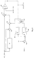
- an internal combustion engine designated 10 generates exhaust gases which are supplied to a three-way catalytic converter designated 12 via an exhaust pipe.
- the three-way catalytic converter 12 is arranged close to the engine 10 (so-called light-off catalyst), so that rapid heating after the start of the internal combustion engine 10 is ensured.
- An exhaust gas valve 13 is also provided in the exhaust gas path in close proximity to the engine 10, by means of which the exhaust gases can be selectively via two different exhaust gas paths 14, 16 with different exhaust gas heat losses can be performed.
- the exhaust gas path 14 has a cooling loop with larger exhaust gas heat losses than in the exhaust gas path 16, which is made as short as possible.
- the exhaust valve 13 is actuated by a two-position actuator 15 (for example a solenoid actuator).
- the exhaust gas valve is shown schematically in FIG. 1 as a changeover valve between the exhaust gas paths 14, 16.
- the exhaust gas paths 14, 16 are designed with significantly different flow resistances, the valve 13 only opening or closing the exhaust gas path with the lower flow resistances.
- the valve 13 when the valve 13 is open, the exhaust gas flows predominantly through the exhaust gas path with the lower flow resistance; when the valve is closed, however, it flows through the exhaust gas path with higher flow resistance.
- a nitrogen oxide trap arrangement 19 is arranged in the exhaust gas path, which has two carriers 18, 20 with a catalyst substrate in a common housing.
- a temperature sensor 24 is provided between the carriers 18, 20.
- the cleaned exhaust gases are discharged via an exhaust system 22.
- the valve actuator 15 and the temperature measurement value of the sensor 24 are connected to a control device which is designed as part of an electronic engine control.
- the engine controller works on a microprocessor basis and has the usual peripherals (ROM, RAM, non-volatile memory, timer and input / output ports), by means of which the engine controller receives a large number of measured engine values and a large number of control signals, e.g. to the ignition and injection system directs.
- the measured value of the temperature sensor 24 is fed to a two-point control element 30, which receives the predetermined target temperature LNT_TMV_T_DES as the target value.
- the signal from the sensor 24 is additionally differentiated at 26 and fed to the control element 30 Value added up at 28.
- the two-point controller 30 provides a binary output signal "heating” (h) or “cooling” (c). This output signal is subjected to a manipulated value limitation and then fed to the actuator 15. When limiting the manipulated value, the binary output signal of the two-point controller 30 is modulated with a square-wave signal.
- the duty cycle is stored in table memories 32, 34.
- two different maps h (heating) and c (cooling) are provided, which contain the duty cycle to be modulated depending on the current exhaust gas mass flow.
- the exhaust gas mass flow approximately corresponds to the air mass flow AM, which is determined by the engine control via an air mass flow sensor (not shown).
- Different maps 32, 34 are provided for different target temperature values LNT_TMV_T_DES.
- the determined duty cycles are converted by a rectangular generator 17 into control patterns for the actuator 15.
- a rectangular generator 17 As shown schematically at 32, in the presence of a "heating" output signal, the valve 13 is constantly held in the position "1" (heating) at low exhaust gas mass flows. The heating output is increasingly reduced at higher exhaust gas mass flows. If a "cooling" output signal is present, cooling is only carried out with reduced power at low exhaust gas mass flows. With higher exhaust gas mass flows, the cooling intensity increases until it reaches its maximum value from a certain exhaust gas mass flow.
- the maps 32, 34 are preferably determined empirically on the engine test bench.
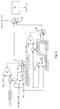
- the structure of the two-point control element is shown in more detail in FIG. 2.
- the digitized measured value of the temperature sensor LNT_T_REAL is compared in a hysteresis comparator 50 with the predetermined target temperature value LNT_TMV_T_DES.
- the target temperature value LNT_TMV_T_DES is specified by a higher-level control unit and can be varied, for example, to carry out a desulfurization cycle.
- the comparator supplies a binary output signal LNT_COOL_FLG.
- a differentiated temperature signal at 52 is added to the actual temperature value before the comparator 50. This is obtained by a low pass filter at 54 and subtraction at 56. The signal obtained in this way is multiplied at 58 by a weighting factor.
- the weighting factor is taken from maps 60 and 62 depending on the output signal LNT_T_COOL_FLG (selection via switch 64).
- the maps contain the weighting factor depending on a quantity LNT_ENERGY, which approximately represents the energy input into the nitrogen oxide trap. At 66, this is determined by dividing the air mass flow AM by the vehicle speed VSBAR (the greater the exhaust gas mass flow, the more thermal energy is supplied to the nitrogen oxide trap; the greater the vehicle speed, on the other hand, the greater the cooling caused by the airstream).
- the weighting factor tends to be increased with greater energy input, so that the control reacts faster to actual temperature trends.
- Fig. 3 the operation of the manipulated value limitation is shown in more detail.
- the key points are the characteristic diagrams FNLNT_COOLDC 70 and FNLNT_HEATDC 72, which contain the duty cycles depending on the exhaust gas mass flow represented by AM and the desired target temperature LNT_TMV_T_DES.
- another variable characterizing the energy input into the nitrogen oxide trap for example the variable LNT_ENERGY from FIG. 2, could also be used as parameters for the characteristic diagrams 70, 72.
- the output signal of the characteristic diagrams 70, 72 is fed through the switch 74 to a square-wave generator 76, which generates the signal for controlling the exhaust gas valve EXHST_DTY created.
- the manipulated value limit can also be deactivated using switches 78, 80. If cooling is provided in accordance with LNT_T_COOL_FLG, this happens when the actual temperature exceeds a predetermined value LNT_TMV_T_DES plus the constant LNT_COOLDCEN. Conversely, for heating, the manipulated value limitation is deactivated when the temperature falls below the target temperature minus the constant LNT_HEATDCEN.
Abstract
Description
- Die Erfindung betrifft ein verfahren zur Regelung der Temperatur einer Abgasbehandlungsanordnung im Abgassystem eines Verbrennungsmotors im Bereich einer vorgegebenen Soll-Temperatur mit einer Veränderungseinrichtung zur Veränderung der Temperatur der die Abgasbehandlungsanordnung durchströmenden Abgase, durch die der Abgasbehandlungsanordnung in Abhängigkeit eines Steuersignals einer Motorsteuerungseinrichtung kühlere oder heißere Abgase zugeführt werden, sowie mit einer Einrichtung zur Bestimmung der Ist-Temperatur der Abgasbehandlungsanordnung und einer Einrichtung zur Bestimmung einer näherungsweise ein Maß für den Energieeintrag in die Abgasbehandlungsanordnung darstellenden Größe sowie eine Vorrichtung zur Durchführung des Verfahrens.
- Eine derartige Temperaturregelung ist insbesondere bei Stickoxidfallen (NOx-Traps), wie sie zur Abgasreinigung bei Motoren mit Magergemischverbrennung (Lean Burn Engines) eingesetzt werden, erforderlich. Während herkömmliche Dreiwegekatalysatoren über einen relativ weiten Temperaturbereich zufriedenstellende Konvertierungsergebnisse erzielen und auch die Empfindlichkeit gegenüber Überhitzung in den letzten Jahren reduziert werden konnte, arbeiten bekannte Stickoxidfallen nur in einem relativ begrenzten Temperaturbereich in zufriedenstellender Weise. Bei niedrigeren Temperaturen adsorbiert die Stickoxidfalle die Schadstoffe nicht ausreichend effizient. Bei zu hohen Temperaturen werden die adsorbierten Schadstoffe teilweise wieder freigesetzt, was die Reinigungseffizienz beeinträchtigt. Bei noch höheren Temperaturen kann die Stickoxidfalle vorschnell altern oder gar dauerhaft beschädigt werden. Angesichts der unter wechselnden Motorbedingungen in einem Bereich zwischen 200 bis 1000°C variierenden Abgastemperaturen ist eine Regelung der die Abgasbehandlungsanordnung durchströmenden Abgase erforderlich.
- In der nicht vorveröffentlichten deutschen Patentanmeldung 197 03 295.8 wird ein Verfahren zur Regelung der Temperatur einer Katalysatoranordnung mit einer Stickoxidfalle vorgeschlagen, bei dem die Temperatur der Stickoxidfalle gemessen und die Stickoxidfalle im Magerbetriebsmodus über eine Einrichtung zur Veränderung der Abgastemperatur in einem dem optimalen Wirkungsgrad der Stickoxidfalle entsprechenden Temperaturbereich betrieben wird. Als Einrichtung zur Abgastemperaturveränderung kann eine Abgasleitung mit zwei, über ein von einem Stellglied angesteuerten Ventil auswählbaren Abgaswegen mit unterschiedlichen Abgaswärmeverlusten verwendet werden. Zur Durchführung der Regelung wird ein PI-Regelglied vorgeschlagen.
- Es hat sich herausgestellt, daß der Temperatursensor im Abgasweg nicht vor, sondern vorzugsweise hinter wenigstens einem Teilelement der Stickoxidfalle angeordnet werden sollte. Diese Anordnung hat den besonderen Vorteil, daß im Fehlerfalle eine drohende Überhitzung der Stickoxidfalle erkannt und vermieden werden kann. Wenn nämlich durch ein Leck im Abgasweg vor der Stickoxidfalle Außenluft in das Abgassystem eindringt, so treten bei Motorbetrieb mit angereichertem Gemisch (z.B. Vollast) exotherme Reaktion mit unverbrannten Kraftstoffbestandteilen auf, die zu einer Überhitzung des Stickoxidfallensubstrats führen können. Wird der Temperatursensor vor der Stickoxidfalle angeordnet, so kann eine derartige Überhitzungsgefahr nicht erkannt werden.
- Die Anordnung hinter wenigstens einem Teilelement der Stickoxidfalle (z.B. zwischen zwei Teilelementen [sog. Bricks] einer Stickoxidfalle) hat jedoch den Nachteil, daß die Regelung wegen der thermischen Trägheit dieses Elementes sehr hohe Totzeiten aufweist. So führt eine Abgastemperaturveränderung erst mit einer Verzögerung von einigen 10 s zu einer entsprechenden Änderung der am Temperatursensor gemessenen Ist-Temperatur. Derartige Systeme sind mit konventionellen PI-Reglern nur schwer zu beherrschen, da nicht akzeptable Regelschwingungen auftreten. Zur Handhabung derartiger Systeme mit großer Totzeit sind sog. Totzeitregelungen vorgeschlagen worden. Bei Totzeitregelungen ist jedoch ein mathematisches Modell des zu regelnden Systems sowie eine vorherige Abschätzung der Totzeit erforderlich. Unter ungewöhnlichen Betriebsbedingungen oder im Fehlerfalle können diese Modelle versagen, so daß es zu einem unkontrollierten Regelungsverhalten kommen kann.
- Der Erfindung liegt die Aufgabe zugrunde, ein Verfahren der eingangs genannten Art zu schaffen, bei dem mit einfachen Mitteln eine ungeachtet der großen Totzeiten unter allen Betriebsbedingungen stabile Temperaturregelung ermöglicht wird.
- Zur Lösung der vorstehend genannten Aufgabe ist vorgesehen, daß die Ist-Temperatur mit der Soll-Temperatur in einem Zweipunkt-Regelglied verglichen wird, welches ein eine Abgaskühlung oder Abgaserwärmung anzeigendes Ausgangssignal erzeugt, und daß aus diesem Ausgangssignal ein modifiziertes Ausgangssignal erzeugt und der Veränderungseinrichtung zugeführt wird, derart, daß bei einem eine Abgaserwärmung anzeigenden Ausgangssignal bei zunehmender Energieeintragsgröße dieses in einer eine Abgaskühlung bewirkenden Richtung modifiziert wird und/oder daß bei einem eine Abgaskühlung anzeigenden Ausgangssignal dieses bei abnehmender Energieeintragsgröße in einer eine Abgaserwärmung bewirkenden Richtung modifiziert wird. Dadurch, daß das Ausgangssignal des Zweipunkt-Regelglieds abgängig von der Energieeintragsgröße modifiziert wird, wird eine Stellwertbegrenzung erreicht und so ein Überschwingen der Temperatur der Abgasbehandlungsanordnung vermieden. Vorzugsweise ist eine Stellwertbegrenzung sowohl bei einem eine Abgaserwärmung als auch bei einem eine Abgaskühlung anzeigenden Ausgangssignal vorgesehen. Es kann jedoch auch eine Stellwertbegrenzung in nur einem der genannten Fälle vorgesehen sein.
- In vorteilhafter Ausgestaltung der Erfindung kann vorgesehen sein, daß die Modifikation durch Modulation des Ausgangssignals mit einem Rechtecksignal erfolgt, dessen Tastverhältnis bei einem eine Abgaserwärmung anzeigenden Ausgangssignal - ausgehend von einem ein ständiges Beheizen anzeigenden Tastverhältnis - bei Überschreiten einer vorgegebenen Motorbetriebsbedingung mit zunehmender Energieeintragsgröße in Richtung einer zunehmenden Abgaskühlung verändert wird und/oder dessen Tastverhältnis bei einem eine Abgaskühlung anzeigenden Ausgangssignal - ausgehend von einem eine ständige Kühlung anzeigenden Tastverhältnis - bei Unterschreiten einer vorgegebenen Motorbetriebsbedingung mit abnehmender Energieeintragsgröße in Richtung einer zunehmenden Abgaserwärmung verändert wird. Das Rechtecksignal weist vorzugsweise eine Periode auf, der der Regelaktuator mechanisch ohne weiteres folgen kann (z.B. 10 s). Durch die thermische Trägheit der Abgasbehandlungsanordnung werden die durch die Modulation bedingten Oszillationen der Abgastemperatur weggemittelt.
- Weiterhin kann vorgesehen sein, daß die Bestimmung der Energieeintragsgröße wenigstens anhand des näherungsweise den aktuellen Abgasmassenstrom repräsentierenden Luftmassenstroms im Einlaßsystem des Verbrennungsmotors erfolgt. Der Abgasmassenstrom ist näherungsweise ein Maß für die Wärmeenergie pro Zeiteinheit, die dem Katalysator zugeführt wird. Je größer dieser Energieeintrag ist, desto schneller paßt sich das Stickoxidfallenmaterial der Abgastemperatur an und desto stärker muß die Stellwertbegrenzung ausfallen. Es können jedoch auch weitere Motorbetriebsparameter bei der Stellwertbegrenzung berücksichtigt werden, wie z.B. die Fahrzeuggeschwindigkeit, die die Wärmeverluste durch den Fahrtwind an der Stickoxidfalle maßgeblich beeinflußt.
- In zweckmäßiger Weise kann außerdem vorgesehen sein, daß das Tastverhältnis anhand eines funktionalen Zusammenhangs abhängig von der Energieeintragsgröße, dem Ausgangssignal des Zweipunkt-Regelglieds sowie anhand des Soll-Temperaturwerts bestimmt wird. Bei dem funktionalen Zusammenhang kann es sich um einen Tabellenspeicher (Kennfeld) oder eine analytische Funktion mit den genannten Indexgrößen bzw. Parametern handeln. Der Soll-Temperaturwert wird üblicherweise während des normalen Motorbetriebes fest vorgegeben. Insbesondere während eines Entschwefelungszyklus bei einer Stickoxidfalle wird die Soll-Temperatur der Stickoxidfalle jedoch erhöht. Da die Strömungs- und Abstrahlungstemperaturverluste sich nicht linear zur Stickoxidfallentemperatur verhalten, sind für unterschiedliche Soll-Temperaturwerte unterschiedliche Tastverhältnis-Kennfelder vorgesehen.
- Das Verhalten des erfindungsgemäßen Regelungsverfahrens kann weiterhin wesentlich dadurch verbessert werden, daß das Zweipunkt-Regelglied mit einem voreilenden Verhalten versehen wird.
- Das voreilende Verhalten kann vorzugsweise durch zeitliche Differenzierung des Ist-Temperatursignals und gewichtete Addition des Ableitungssignals zu dem Ist-Temperatursignal und Zuführung des Summensignals zu dem Komparator des Zweipunkt-Regelglieds realisiert werden. Dadurch wird die Änderungsgeschwindigkeit des Ist-Temperatursignals mit in die Regelung einbezogen, so daß einem Überschwingen bereits frühzeitig entgegengewirkt werden kann.
- Der Gewichtungsfaktor des Ableitungssignals kann vorzugsweise abhängig vom Ausgangssignal des Zweipunkt-Regelglieds und abhängig von einer den Energieeintrag in die Abgasbehandlungsanordnung repräsentierenden Größe bestimmt werden. So kann die Regelung bei größerem Energieeintrag empfindlicher auf Änderungen des Ist-Temperaturwertes reagieren.
- Bei einer Vorrichtung zur Durchführung des Verfahrens weist die Veränderungseinrichtung ein Abgasventil mit zwei Stellungen auf, bei denen das Abgas über zwei Abgaswege mit unterschiedlichen Wärmeverlusten geführt wird, und die Einrichtung zur Bestimmung der Ist-Temperatur der Abgasbehandlungsanordnung weist einen Temperatursensor auf, der im Abgasweg hinter wenigstens einem Teilelement der Abgasbehandlungsanordnung angeordnet ist. Durch diese Anordnung wird die Temperatur der Abgasbehandlungsanordnung auch im Fehlerfalle, bei dem eine exotherme Reaktion in der Abgasbehandlungsanordnung stattfinden kann, sicher erkannt und bei der Regelung berücksichtigt.
- Ein Vorteil des erfindungsgemäßen Verfahrens besteht darin, daß die Regelung auf der Grundlage eines einfachen und robusten Zweipunkt-Regelglieds durchgeführt werden kann. Insbesondere sind keine Temperaturmodelle der Abgasbehandlungsanordnung oder Annahmen über die Totzeit des Regelkreises erforderlich. Trotz der vorhandenen großen Totzeiten wird ein gutes Regelverhalten erzielt.
- Ein weiterer Vorteil des erfindungsgemäßen Verfahrens besteht darin, daß ein binäres Stellsignal erzeugt wird. Somit kann ein kostengünstiger Zweistellungs-Aktuator verwendet werden, der ohne einen Sensor für die Lagerückmeldung auskommt.
- Die Erfindung wird nachfolgend anhand der Zeichnungen beispielhaft näher erläutert.
- Es zeigen:
- Fig. 1
- eine schematische Darstellung einer Abgasanlage eines Verbrennungsmotors sowie ein schematisches Blockdiagramm des erfindungsgemäßen Verfahrens,
- Fig. 2
- eine detaillierteres Blockdiagramm des erfindungsgemäßen Zweipunktregelalgorithmus, und
- Fig. 3
- ein detaillierteres Blockdiagramm des erfindungsgemäßen Stellwertbegrenzungbegrenzungsalgorithmus.
- Gemäß Fig. 1 erzeugt ein mit 10 bezeichneter Verbrennungsmotor Abgase, die über ein Abgasrohr einem mit 12 bezeichneten Dreiwegekatalysator zugeführt werden. Der Dreiwegekatalysator 12 ist nahe am Motor 10 angeordnet (sog. Light Off Catalyst), so daß eine schnelle Aufheizung nach dem Start des Verbrennungsmotors 10 gewährleistet ist. Im Abgasweg ist ebenfalls in räumlicher Nähe des Motors 10 ein Abgasventil 13 vorgesehen, mittels dessen die Abgase wahlweise über zwei verschiedene Abgaswege 14, 16 mit unterschiedlichen Abgaswärmeverlusten geführt werden können. Der Abgasweg 14 weist eine Kühlschleife mit größeren Abgaswärmeverlusten als beim Abgasweg 16 auf, der so kurz wie möglich ausgebildet ist. Das Abgasventil 13 wird von einem Zweistellungs-Aktuator 15 (z.B. einem Solenoid-Aktuator) betätigt. Das Abgasventil ist in Fig. 1 schematisch als Umschaltventil zwischen den Abgaswegen 14, 16 dargestellt. Es kann aber auch vorgesehen sein, daß die Abgaswege 14, 16 mit deutlich unterschiedlichen Strömungswiderständen ausgebildet sind, wobei das Ventil 13 lediglich den Abgasweg mit den geringeren Strömungwiderständen öffnet bzw. verschließt. Bei offenem Ventil 13 strömt in diesem Falle das Abgas überwiegend durch den Abgasweg mit dem niedrigeren Strömungswiderstand; bei geschlossenem Ventil strömt es dagegen durch den Abgasweg mit höherem Strömungswiderstand. In räumlicher Entfernung vom Verbrennungsmotor 10 ist im Abgasweg eine Stickoxidfallenanordnung 19 angeordnet, die in einem gemeinsamen Gehäuse zwei Träger 18, 20 mit Katalysatorsubstrat aufweist. Zwischen den Trägern 18, 20 ist ein Temperatursensor 24 vorgesehen. Die gereinigten Abgase werden über eine Auspuffanlage 22 abgeführt.
- Der Ventilaktuator 15 sowie der Temperaturmeßwert des Sensors 24 stehen mit einer Regelungseinrichtung in Verbindung, die als Teil einer elektronischen Motorsteuerung ausgebildet ist. Die Motorsteuerung arbeitet auf Mikroprozessor-Basis und weist die übliche Peripherie (ROM, RAM, nicht flüchtiger Speicher, Zeitgeber sowie Ein/Ausgabe-Ports) auf, mittels derer die Motorsteuerung eine Vielzahl von Motormeßwerten empfängt und eine Vielzahl von Steuersignalen z.B. an die Zünd- und Einspritzanlage leitet. Der Meßwert des Temperatursensors 24 wird einem Zweipunkt-Regelglied 30 zugeführt, der als Sollwert die vorgegebene Solltemperatur LNT_TMV_T_DES erhält. Das Signal des Sensors 24 wird bei 26 zusätzlich differenziert und auf den dem Regelglied 30 zugeführten Wert bei 28 aufaddiert. Der Zweipunkt-Regler 30 liefert ein binäres Ausgangssignal "Heizen" (h) oder "Kühlen" (c). Dieses Ausgangssignal wird einer Stellwertbegrenzung unterzogen und anschließend dem Aktuator 15 zugeführt. Bei der Stellwertbegrenzung wird das binäre Ausgangssignal des Zweipunkt-Reglers 30 mit einem Rechtecksignal moduliert. Das Tastverhältnis ist in Tabellenspeichern 32, 34 gespeichert. Abhängig vom Ausgangssignal sind jeweils zwei verschiedene Kennfelder h (Heizen) und c (Kühlen) vorgesehen, die die aufzumodulierenden Tastverhältnisse abhängig vom aktuellen Abgasmassenstrom enthalten. Der Abgasmassenstrom entspricht näherungsweise dem Luftmassenstrom AM, der von der Motorsteuerung über einen (nicht dargestellten) Luftmassenstromsensor bestimmt wird. Für unterschiedliche Soll-Temperaturwerte LNT_TMV_T_DES sind jeweils unterschiedliche Kennfelder 32, 34 vorgesehen. Die ermittelten Tastverhältnisse werden von einem Rechteckgenerator 17 in Ansteuerungsmuster für den Aktuator 15 umgesetzt. Wie bei 32 schematisch dargestellt, wird bei Vorliegen eines "Heizen"-Ausgangssignals das Ventil 13 bei niedrigen Abgasmassenströmen ständig in der Stellung "1" (Heizen) gehalten. Bei höheren Abgasmassenströmen wird die Heizleistung zunehmend reduziert. Bei Vorliegen eines "Kühlen"-Ausgangssignals wird bei niedrigen Abgasmassenströmen nur mit reduzierter Leistung gekühlt. Bei höheren Abgasmassenströmen steigt die Kühlintensität, bis diese ab einem bestimmten Abgasmassenstrom ihren Maximalwert erreicht. Die Kennfelder 32, 34 werden vorzugsweise empirisch am Motorprüfstand bestimmt.
- In Fig. 2 ist der Aufbau des Zweipunkt-Regelglieds detaillierter gezeigt. Der digitalisierte Meßwert des Temperatursensors LNT_T_REAL wird in einem hysteresebehafteten Komparator 50 mit dem vorgegebenen Soll-Temperaturwert LNT_TMV_T_DES verglichen. Der Soll-Temperaturwert LNT_TMV_T_DES wird von einer übergeordneten Steuereinheit vorgegeben und kann z.B. zur Durchführung eines Entschwefelungszyklus variiert werden. Der Komparator liefert ein binäres Ausgangssignal LNT_COOL_FLG. Auf den Ist-Temperaturwert wird vor dem Komparator 50 ein differenziertes Temperatursignal bei 52 aufaddiert. Dieses wird durch ein Tiefpaßfilter bei 54 und Subtraktion bei 56 gewonnen. Das so gewonnene Signal wird bei 58 mit einem Gewichtungsfaktor multipliziert. Der Gewichtungsfaktor wird abhängig vom Ausgangssignal LNT_T_COOL_FLG aus Kennfeldern 60 bzw. 62 (Auswahl über Schalter 64) entnommen. Die Kennfelder enthalten den Gewichtungsfaktor abhängig von einer Größe LNT_ENERGY, die näherungsweise den Energieeintrag in die Stickoxidfalle repräsentiert. Diese wird bei 66 durch Division des Luftmassenstroms AM durch die Fahrzeuggeschwindigkeit VSBAR bestimmt (je größer der Abgasmassenstrom ist, desto mehr Wärmeenergie wird der Stickoxidfalle zugeführt; je größer dagegen die Fahrzeuggeschwindigkeit ist, desto größer ist die Abkühlung durch den Fahrtwind). Der Gewichtungsfaktor wird tendenziell bei größerem Energieeintrag erhöht, so daß die Regelung schneller auf Ist-Temperaturtendenzen reagiert.
- In Fig. 3 ist die Funktionsweise der Stellwertbegrenzung detaillierter dargestellt. Kernpunkt sind die Kennfelder FNLNT_COOLDC 70 bzw. FNLNT_HEATDC 72, die die Tastverhältnisse abhängig vom Abgasmassenstrom repräsentiert durch AM und der gewünschten Soll-Temperatur LNT_TMV_T_DES enthalten. Alternativ könnte auch eine andere den Energieeintrag in die Stickoxidfalle charakterisierende Größe, z.B. die Größe LNT_ENERGY aus Fig. 2, als Parameter für die Kennfelder 70, 72 verwendet werden. Das Ausgangssignal der Kennfelder 70, 72 wird abhängig von dem gemäß Fig. 2 bestimmten Flag LNT_T_COOL_FLG durch den Schalter 74 einem Rechteckgenerator 76 zugeführt, der das Signal zur Ansteuerung des Abgasventils EXHST_DTY erzeugt. Die Stellwertbegrenzung kann zusätzlich durch Schalter 78, 80 deaktiviert werden. Falls gemäß LNT_T_COOL_FLG eine Kühlung vorgesehen ist, geschieht dies, wenn die Ist-Temperatur einen vorgegebenen Wert LNT_TMV_T_DES zuzüglich der Konstante LNT_COOLDCEN überschreitet. Umgekehrt wird bei Heizung die Stellwertbegrenzung bei Unterschreiten der Solltemperatur abzüglich der Konstante LNT_HEATDCEN deaktiviert.
Claims (8)
- Verfahren zur Regelung der Temperatur einer Abgasbehandlungsanordnung im Abgassystem eines Verbrennungsmotors im Bereich einer vorgegebenen Soll-Temperatur mit einer Veränderungseinrichtung zur Veränderung der Temperatur der die Abgasbehandlungsanordnung durchströmenden Abgase, durch die der Abgasbehandlungsanordnung in Abhängigkeit eines Steuersignals einer Motorsteuerungseinrichtung kühlere oder heißere Abgase zugeführt werden, sowie mit einer Einrichtung zur Bestimmung der Ist-Temperatur der Abgasbehandlungsanordnung und einer Einrichtung zur Bestimmung einer näherungsweise ein Maß für den Energieeintrag in die Abgasbehandlungsanordnung darstellenden Größe, dadurch gekennzeichnet, daß die Ist-Temperatur mit der Soll-Temperatur in einem Zweipunkt-Regelglied (30) verglichen wird, welches ein eine Abgaskühlung oder Abgaserwärmung anzeigendes Ausgangssignal erzeugt, und daß aus diesem Ausgangssignal ein modifiziertes Ausgangssignal erzeugt und der Veränderungseinrichtung zugeführt wird, derart, daß bei einem eine Abgaserwärmung anzeigenden Ausgangssignal bei zunehmender Energieeintragsgröße dieses in einer eine Abgaskühlung bewirkenden Richtung modifiziert wird und/oder daß bei einem eine Abgaskühlung anzeigenden Ausgangssignal dieses bei abnehmender Energieeintragsgröße in einer eine Abgaserwärmung bewirkenden Richtung modifiziert wird.
- Verfahren nach Anspruch 1, dadurch gekennzeichnet, daß die Modifikation durch Modulation des Ausgangssignals mit einem Rechtecksignal erfolgt, dessen Tastverhältnis bei einem eine Abgaserwärmung anzeigenden Ausgangssignal - ausgehend von einem ein ständiges Beheizen anzeigenden Tastverhältnis - bei Überschreiten einer vorgegebenen Motorbetriebsbedingung mit zunehmender Energieeintragsgröße in Richtung einer zunehmenden Abgaskühlung verändert wird und/oder dessen Tastverhältnis bei einem eine Abgaskühlung anzeigenden Ausgangssignal - ausgehend von einem eine ständige Kühlung anzeigenden Tastverhältnis - bei Unterschreiten einer vorgegebenen Motorbetriebsbedingung mit abnehmender Energieeintragsgröße in Richtung einer zunehmenden Abgaserwärmung verändert wird.
- Verfahren nach Anspruch 1 oder 2, dadurch gekennzeichnet, daß die Bestimmung der Energieeintragsgröße wenigstens anhand des näherungsweise den aktuellen Abgasmassenstrom repräsentierenden Luftmassenstroms (AM) im Einlaßsystem des Verbrennungsmotors erfolgt.
- Verfahren nach einem der Ansprüche 1 bis 3, dadurch gekennzeichnet, daß das Tastverhältnis anhand eines funktionalen Zusammenhangs abhängig von der Energieeintragsgröße, dem Ausgangssignal des Zweipunkt-Regelglieds (39) sowie anhand des Soll-Temperaturwerts bestimmt wird.
- Verfahren nach einem der Ansprüche 1 bis 4, dadurch gekennzeichnet, daß das Zweipunkt-Regelglied ein voreilendes Verhalten aufweist.
- Verfahren nach Anspruch 5, dadurch gekennzeichnet, daß das voreilende Verhalten durch zeitliche Differenzierung des Ist-Temperatursignals und gewichtete Addition des Ableitungssignals zu dem Ist-Temperatursignal und Zuführung des Summensignals zu dem Komparator des Zweipunkt-Regelglieds realisiert wird.
- Verfahren nach Anspruch 6, dadurch gekennzeichnet, daß der Gewichtungsfaktor des Ableitungssignals abhängig vom Ausgangssignal des Zweipunkt-Regelglieds und abhängig von einer den Energieeintrag in die Abgasbehandlungsanordnung repräsentierenden Größe bestimmt wird.
- Vorrichtung zur Durchführung des Verfahrens nach einem der Ansprüche 1 bis 7, dadurch gekennzeichnet, daß die Veränderungseinrichtung ein Abgasventil (13) mit zwei Stellungen, bei denen das Abgas über zwei Abgaswege (14, 16) mit unterschiedlichen Wärmeverlusten geführt wird, aufweist und daß die Einrichtung zur Bestimmung der Ist-Temperatur der Abgasbehandlungsanordnung einen Temperatursensor (24) aufweist, der im Abgasweg hinter wenigstens einem Teilelement (18) der Abgasbehandlungsanordnung (19) angeordnet ist.
Applications Claiming Priority (2)
| Application Number | Priority Date | Filing Date | Title |
|---|---|---|---|
| DE19817650A DE19817650C2 (de) | 1998-04-21 | 1998-04-21 | Verfahren und Vorrichtung zur Regelung der Temperatur einer Abgasbehandlungsanordnung |
| DE19817650 | 1998-04-21 |
Publications (3)
| Publication Number | Publication Date |
|---|---|
| EP0952319A2 true EP0952319A2 (de) | 1999-10-27 |
| EP0952319A3 EP0952319A3 (de) | 2003-01-29 |
| EP0952319B1 EP0952319B1 (de) | 2004-08-11 |
Family
ID=7865228
Family Applications (1)
| Application Number | Title | Priority Date | Filing Date |
|---|---|---|---|
| EP99103238A Expired - Lifetime EP0952319B1 (de) | 1998-04-21 | 1999-02-19 | Verfahren und Vorrichtung zur Regelung der Temperatur einer Abgasbehandlungsanordnung |
Country Status (4)
| Country | Link |
|---|---|
| US (1) | US6185935B1 (de) |
| EP (1) | EP0952319B1 (de) |
| JP (1) | JPH11324660A (de) |
| DE (2) | DE19817650C2 (de) |
Families Citing this family (13)
| Publication number | Priority date | Publication date | Assignee | Title |
|---|---|---|---|---|
| DE19959610A1 (de) * | 1999-12-10 | 2001-06-13 | Volkswagen Ag | Verfahren zum Aufheizen eines Katalysators insbesondere im Leerlaufbetrieb eines magerlauffähigen Verbrennungsmotors eines Fahrzeugs |
| DE19963925A1 (de) * | 1999-12-31 | 2001-07-12 | Bosch Gmbh Robert | Verfahren zum Betreiben eines Speicherkatalysators einer Brennkraftmaschine |
| US6460346B1 (en) * | 2000-08-30 | 2002-10-08 | General Electric Company | Method and system for identifying malfunctioning combustion chambers in a gas turbine |
| US6568179B2 (en) * | 2001-03-01 | 2003-05-27 | Engelhard Corporation | Apparatus and method for vehicle emissions control |
| DE10139424B4 (de) * | 2001-08-17 | 2004-08-05 | Benteler Automobiltechnik Gmbh | Abgasanlage eines Kraftfahrzeugs |
| DE10145916B4 (de) * | 2001-09-18 | 2014-01-02 | Volkswagen Ag | Verfahren und Vorrichtung zum Abkühlen einer Katalysatoreinrichtung |
| US7533518B2 (en) * | 2005-05-12 | 2009-05-19 | Ford Global Technologies, Llc | System and method for reducing NOx emissions in an apparatus having a diesel engine |
| US7707826B2 (en) | 2006-11-07 | 2010-05-04 | Cummins, Inc. | System for controlling triggering of adsorber regeneration |
| US7533523B2 (en) * | 2006-11-07 | 2009-05-19 | Cummins, Inc. | Optimized desulfation trigger control for an adsorber |
| US7594392B2 (en) * | 2006-11-07 | 2009-09-29 | Cummins, Inc. | System for controlling adsorber regeneration |
| US7654076B2 (en) * | 2006-11-07 | 2010-02-02 | Cummins, Inc. | System for controlling absorber regeneration |
| US7654079B2 (en) * | 2006-11-07 | 2010-02-02 | Cummins, Inc. | Diesel oxidation catalyst filter heating system |
| US8855894B2 (en) * | 2008-11-04 | 2014-10-07 | GM Global Technology Operations LLC | Exhaust temperature and pressure modeling systems and methods |
Citations (6)
| Publication number | Priority date | Publication date | Assignee | Title |
|---|---|---|---|---|
| DE4218834A1 (de) * | 1992-06-09 | 1993-12-16 | Opel Adam Ag | Abgasanlage für einen Verbrennungsmotor |
| US5588291A (en) * | 1992-12-09 | 1996-12-31 | Emitec Gesellschaft Fuer Emissionstechnologie Mbh | Method for controlling the heating of an electrically heatable catalytic converter |
| JPH0932540A (ja) * | 1995-07-13 | 1997-02-04 | Hino Motors Ltd | ディーゼルエンジンの排ガス浄化装置 |
| US5642705A (en) * | 1994-09-29 | 1997-07-01 | Fuji Jukogyo Kabushiki Kaisha | Control system and method for direct fuel injection engine |
| EP0867603A1 (de) * | 1997-03-28 | 1998-09-30 | Ford Global Technologies, Inc. | Temperaturregelungsverfahren und -system einer Abgasanlage |
| EP0905355A2 (de) * | 1997-09-27 | 1999-03-31 | Ford Global Technologies, Inc. | Abgasanlage für einen Verbrennungsmotor |
Family Cites Families (9)
| Publication number | Priority date | Publication date | Assignee | Title |
|---|---|---|---|---|
| US3957444A (en) * | 1972-05-16 | 1976-05-18 | Toyota Jidosha Kogyo Kabushiki Kaisha | Control system for exhaust gas purifying device |
| DE4106308C2 (de) * | 1991-02-28 | 2000-06-15 | Bosch Gmbh Robert | Verfahren und Vorrichtung zur Temperaturregelung für eine Abgassonde |
| JP2783074B2 (ja) * | 1991-10-29 | 1998-08-06 | トヨタ自動車株式会社 | 内燃機関の排気浄化装置 |
| DE4139561A1 (de) * | 1991-11-30 | 1993-06-03 | Bosch Gmbh Robert | Verfahren und vorrichtung zum ueberwachen des alterungszustandes einer sauerstoffsonde |
| DE4140618A1 (de) * | 1991-12-10 | 1993-06-17 | Bosch Gmbh Robert | Verfahren und vorrichtung zur ermittlung der konvertierungsfaehigkeit eines katalysators |
| US5388404A (en) * | 1992-06-09 | 1995-02-14 | Mitsubishi Denki Kabushiki Kaisha | Controller device for electrically heated catalyst of automotive engine |
| US5657625A (en) * | 1994-06-17 | 1997-08-19 | Mitsubishi Jidosha Kogyo Kabushiki Kaisha | Apparatus and method for internal combustion engine control |
| DE19626405B4 (de) * | 1995-06-30 | 2008-09-18 | Denso Corp., Kariya | Luft/Kraftstoff-Verhältnis-Steuervorrichtung für einen Verbrennungsmotor |
| DE19703295C2 (de) * | 1997-01-30 | 2000-06-29 | Ford Global Tech Inc | Verfahren zur Regelung der Temperatur einer Katalysatoranordnung sowie Vorrichtung zur Durchführung des Verfahrens |
-
1998
- 1998-04-21 DE DE19817650A patent/DE19817650C2/de not_active Expired - Fee Related
-
1999
- 1999-02-19 DE DE59910164T patent/DE59910164D1/de not_active Expired - Fee Related
- 1999-02-19 EP EP99103238A patent/EP0952319B1/de not_active Expired - Lifetime
- 1999-04-20 JP JP11112397A patent/JPH11324660A/ja active Pending
- 1999-04-23 US US09/298,157 patent/US6185935B1/en not_active Expired - Lifetime
Patent Citations (6)
| Publication number | Priority date | Publication date | Assignee | Title |
|---|---|---|---|---|
| DE4218834A1 (de) * | 1992-06-09 | 1993-12-16 | Opel Adam Ag | Abgasanlage für einen Verbrennungsmotor |
| US5588291A (en) * | 1992-12-09 | 1996-12-31 | Emitec Gesellschaft Fuer Emissionstechnologie Mbh | Method for controlling the heating of an electrically heatable catalytic converter |
| US5642705A (en) * | 1994-09-29 | 1997-07-01 | Fuji Jukogyo Kabushiki Kaisha | Control system and method for direct fuel injection engine |
| JPH0932540A (ja) * | 1995-07-13 | 1997-02-04 | Hino Motors Ltd | ディーゼルエンジンの排ガス浄化装置 |
| EP0867603A1 (de) * | 1997-03-28 | 1998-09-30 | Ford Global Technologies, Inc. | Temperaturregelungsverfahren und -system einer Abgasanlage |
| EP0905355A2 (de) * | 1997-09-27 | 1999-03-31 | Ford Global Technologies, Inc. | Abgasanlage für einen Verbrennungsmotor |
Non-Patent Citations (1)
| Title |
|---|
| PATENT ABSTRACTS OF JAPAN vol. 1997, no. 06, 30. Juni 1997 (1997-06-30) & JP 09 032540 A (HINO MOTORS LTD), 4. Februar 1997 (1997-02-04) * |
Also Published As
| Publication number | Publication date |
|---|---|
| DE59910164D1 (de) | 2004-09-16 |
| EP0952319B1 (de) | 2004-08-11 |
| DE19817650C2 (de) | 2002-05-08 |
| EP0952319A3 (de) | 2003-01-29 |
| US6185935B1 (en) | 2001-02-13 |
| DE19817650A1 (de) | 1999-11-04 |
| JPH11324660A (ja) | 1999-11-26 |
Similar Documents
| Publication | Publication Date | Title |
|---|---|---|
| EP0952319A2 (de) | Verfahren und Vorrichtung zur Regelung der Temperatur einer Abgasbehandlungsanordnung | |
| DE102005057449A1 (de) | Verfahren und System zum Steuern des in Abgasen enthaltenen Kraftstoffes zur Unterstützung der Regeneration eines Partikelfilters | |
| DE4343353C2 (de) | Verfahren und Vorrichtung zum Steuern einer Brennkraftmaschine | |
| DE19629068C2 (de) | Vorrichtung zum Steuern der Motorleerlaufdrehzahl | |
| DE4402850A1 (de) | System zur Überwachung und Steuerung von Verbrennungsmotoren und deren Abgasemissionen unter Verwendung von Gassensoren | |
| DE102005058020A1 (de) | Verfahren und System zum Steuern der Temperaturen von Abgasen aus einem Verbrennungsmotor zur Unterstützung der Regeneration eines Partikelfilters | |
| DE102004030270A1 (de) | Nutzung von Motorparametern für Kondensationsverhinderungsstrategien | |
| DE19959854A1 (de) | Verfahren zur Abgasrückführung in einem Luftansaugbereich von Fahrzeug-Brennkraftmaschinen sowie Vorrichtung | |
| DE19753842A1 (de) | Verfahren zum Betreiben eines Abgaskatalysators für eine Brennkraftmaschine | |
| DE102005061876A1 (de) | Verfahren und Vorrichtung zur Steuerung eines Abgasnachbehandlungssystems | |
| DE102005057086A1 (de) | Verfahren und System zum Steuern der aus einem Verbrennungsmotor ausgestoßenen Abgase | |
| DE19801976A1 (de) | Kraftstoffzufuhr-Steuer/Regel-System für Brennkraftmaschinen | |
| DE4141946C2 (de) | Verfahren und Vorrichtung zur Steuerung des Betriebs einer Sekundärluftpumpe | |
| DE102020006010A1 (de) | Verbrennungsmotor mit einem Steuergerät zur Koordination zwischen Maßnahmen in einer Abgasanlage und einer Parametrisierung des Verbrennungsmotors | |
| EP0856645B1 (de) | Verfahren zur Regelung der Temperatur einer Katalysatoranordnung sowie Vorrichtung zur Durchführung des Verfahrens | |
| DE19539937C2 (de) | Verfahren zur Steuerung des Abgasverhältnisses von Kraftstoff zu Sauerstoff im Abgastrakt vor einem Katalysator | |
| DE19838032A1 (de) | Verfahren zur Regeneration eines Partikelfilters | |
| EP1329627B1 (de) | Verfahren und Vorrichtung zum Steuern einer Bauteilschutzfunktion | |
| DE19851843A1 (de) | Verfahren zur Sulfatregeneration eines NOx-Speicherkatalysators für eine Mager-Brennkraftmaschine | |
| DE10023911A1 (de) | Steuereinheit mit Rückkopplungssystem | |
| DE102006017300B4 (de) | Verfahren zur Regeneration von zumindest einer oxidierend arbeitenden Abgasreinigungseinrichtung und zumindest einer reduzierend arbeitenden Abgasreinigungseinrichtung sowie Vorrichtung zum Durchführen des Verfahrens | |
| DE4412742A1 (de) | Katalysatorsystem | |
| DE19519378A1 (de) | Kühlanlage mit elektrisch regelbarem Stellglied | |
| DE3028091C2 (de) | Luftbrennstoffverhältnisregelsystem für einen Verbrennungsmotor | |
| DE102020100434A1 (de) | Verfahren zum Betreiben einer Antriebseinrichtung für ein Kraftfahrzeug sowie entsprechende Antriebseinrichtung |
Legal Events
| Date | Code | Title | Description |
|---|---|---|---|
| PUAI | Public reference made under article 153(3) epc to a published international application that has entered the european phase |
Free format text: ORIGINAL CODE: 0009012 |
|
| AK | Designated contracting states |
Kind code of ref document: A2 Designated state(s): AT BE CH CY DE DK ES FI FR GB GR IE IT LI LU MC NL PT SE |
|
| AX | Request for extension of the european patent |
Free format text: AL;LT;LV;MK;RO;SI |
|
| PUAL | Search report despatched |
Free format text: ORIGINAL CODE: 0009013 |
|
| AK | Designated contracting states |
Designated state(s): AT BE CH CY DE DK ES FI FR GB GR IE IT LI LU MC NL PT SE |
|
| AX | Request for extension of the european patent |
Extension state: AL LT LV MK RO SI |
|
| 17P | Request for examination filed |
Effective date: 20030718 |
|
| 17Q | First examination report despatched |
Effective date: 20030825 |
|
| AKX | Designation fees paid |
Designated state(s): DE FR GB IT SE |
|
| GRAP | Despatch of communication of intention to grant a patent |
Free format text: ORIGINAL CODE: EPIDOSNIGR1 |
|
| GRAS | Grant fee paid |
Free format text: ORIGINAL CODE: EPIDOSNIGR3 |
|
| GRAA | (expected) grant |
Free format text: ORIGINAL CODE: 0009210 |
|
| AK | Designated contracting states |
Kind code of ref document: B1 Designated state(s): DE FR GB IT SE |
|
| PG25 | Lapsed in a contracting state [announced via postgrant information from national office to epo] |
Ref country code: IT Free format text: LAPSE BECAUSE OF FAILURE TO SUBMIT A TRANSLATION OF THE DESCRIPTION OR TO PAY THE FEE WITHIN THE PRESCRIBED TIME-LIMIT;WARNING: LAPSES OF ITALIAN PATENTS WITH EFFECTIVE DATE BEFORE 2007 MAY HAVE OCCURRED AT ANY TIME BEFORE 2007. THE CORRECT EFFECTIVE DATE MAY BE DIFFERENT FROM THE ONE RECORDED. Effective date: 20040811 |
|
| REG | Reference to a national code |
Ref country code: GB Ref legal event code: FG4D Free format text: NOT ENGLISH |
|
| REG | Reference to a national code |
Ref country code: IE Ref legal event code: FG4D Free format text: GERMAN |
|
| REF | Corresponds to: |
Ref document number: 59910164 Country of ref document: DE Date of ref document: 20040916 Kind code of ref document: P |
|
| PG25 | Lapsed in a contracting state [announced via postgrant information from national office to epo] |
Ref country code: SE Free format text: LAPSE BECAUSE OF FAILURE TO SUBMIT A TRANSLATION OF THE DESCRIPTION OR TO PAY THE FEE WITHIN THE PRESCRIBED TIME-LIMIT Effective date: 20041111 |
|
| GBT | Gb: translation of ep patent filed (gb section 77(6)(a)/1977) |
Effective date: 20041201 |
|
| REG | Reference to a national code |
Ref country code: IE Ref legal event code: FD4D |
|
| ET | Fr: translation filed | ||
| PLBE | No opposition filed within time limit |
Free format text: ORIGINAL CODE: 0009261 |
|
| STAA | Information on the status of an ep patent application or granted ep patent |
Free format text: STATUS: NO OPPOSITION FILED WITHIN TIME LIMIT |
|
| 26N | No opposition filed |
Effective date: 20050512 |
|
| REG | Reference to a national code |
Ref country code: FR Ref legal event code: TP |
|
| PGFP | Annual fee paid to national office [announced via postgrant information from national office to epo] |
Ref country code: GB Payment date: 20080108 Year of fee payment: 10 Ref country code: DE Payment date: 20080229 Year of fee payment: 10 |
|
| PGFP | Annual fee paid to national office [announced via postgrant information from national office to epo] |
Ref country code: FR Payment date: 20080212 Year of fee payment: 10 |
|
| GBPC | Gb: european patent ceased through non-payment of renewal fee |
Effective date: 20090219 |
|
| REG | Reference to a national code |
Ref country code: FR Ref legal event code: ST Effective date: 20091030 |
|
| PG25 | Lapsed in a contracting state [announced via postgrant information from national office to epo] |
Ref country code: DE Free format text: LAPSE BECAUSE OF NON-PAYMENT OF DUE FEES Effective date: 20090901 |
|
| PG25 | Lapsed in a contracting state [announced via postgrant information from national office to epo] |
Ref country code: GB Free format text: LAPSE BECAUSE OF NON-PAYMENT OF DUE FEES Effective date: 20090219 Ref country code: FR Free format text: LAPSE BECAUSE OF NON-PAYMENT OF DUE FEES Effective date: 20090302 |