EP0952795B1 - Splittable sleeve, stent deployment device - Google Patents
Splittable sleeve, stent deployment device Download PDFInfo
- Publication number
- EP0952795B1 EP0952795B1 EP97947517A EP97947517A EP0952795B1 EP 0952795 B1 EP0952795 B1 EP 0952795B1 EP 97947517 A EP97947517 A EP 97947517A EP 97947517 A EP97947517 A EP 97947517A EP 0952795 B1 EP0952795 B1 EP 0952795B1
- Authority
- EP
- European Patent Office
- Prior art keywords
- sleeve
- stent
- catheter
- balloon
- splitting
- Prior art date
- Legal status (The legal status is an assumption and is not a legal conclusion. Google has not performed a legal analysis and makes no representation as to the accuracy of the status listed.)
- Expired - Lifetime
Links
Images


Classifications
-
- A—HUMAN NECESSITIES
- A61—MEDICAL OR VETERINARY SCIENCE; HYGIENE
- A61F—FILTERS IMPLANTABLE INTO BLOOD VESSELS; PROSTHESES; DEVICES PROVIDING PATENCY TO, OR PREVENTING COLLAPSING OF, TUBULAR STRUCTURES OF THE BODY, e.g. STENTS; ORTHOPAEDIC, NURSING OR CONTRACEPTIVE DEVICES; FOMENTATION; TREATMENT OR PROTECTION OF EYES OR EARS; BANDAGES, DRESSINGS OR ABSORBENT PADS; FIRST-AID KITS
- A61F2/00—Filters implantable into blood vessels; Prostheses, i.e. artificial substitutes or replacements for parts of the body; Appliances for connecting them with the body; Devices providing patency to, or preventing collapsing of, tubular structures of the body, e.g. stents
- A61F2/95—Instruments specially adapted for placement or removal of stents or stent-grafts
- A61F2/962—Instruments specially adapted for placement or removal of stents or stent-grafts having an outer sleeve
- A61F2/97—Instruments specially adapted for placement or removal of stents or stent-grafts having an outer sleeve the outer sleeve being splittable
-
- A—HUMAN NECESSITIES
- A61—MEDICAL OR VETERINARY SCIENCE; HYGIENE
- A61F—FILTERS IMPLANTABLE INTO BLOOD VESSELS; PROSTHESES; DEVICES PROVIDING PATENCY TO, OR PREVENTING COLLAPSING OF, TUBULAR STRUCTURES OF THE BODY, e.g. STENTS; ORTHOPAEDIC, NURSING OR CONTRACEPTIVE DEVICES; FOMENTATION; TREATMENT OR PROTECTION OF EYES OR EARS; BANDAGES, DRESSINGS OR ABSORBENT PADS; FIRST-AID KITS
- A61F2/00—Filters implantable into blood vessels; Prostheses, i.e. artificial substitutes or replacements for parts of the body; Appliances for connecting them with the body; Devices providing patency to, or preventing collapsing of, tubular structures of the body, e.g. stents
- A61F2/95—Instruments specially adapted for placement or removal of stents or stent-grafts
- A61F2/958—Inflatable balloons for placing stents or stent-grafts
-
- A—HUMAN NECESSITIES
- A61—MEDICAL OR VETERINARY SCIENCE; HYGIENE
- A61F—FILTERS IMPLANTABLE INTO BLOOD VESSELS; PROSTHESES; DEVICES PROVIDING PATENCY TO, OR PREVENTING COLLAPSING OF, TUBULAR STRUCTURES OF THE BODY, e.g. STENTS; ORTHOPAEDIC, NURSING OR CONTRACEPTIVE DEVICES; FOMENTATION; TREATMENT OR PROTECTION OF EYES OR EARS; BANDAGES, DRESSINGS OR ABSORBENT PADS; FIRST-AID KITS
- A61F2/00—Filters implantable into blood vessels; Prostheses, i.e. artificial substitutes or replacements for parts of the body; Appliances for connecting them with the body; Devices providing patency to, or preventing collapsing of, tubular structures of the body, e.g. stents
- A61F2/95—Instruments specially adapted for placement or removal of stents or stent-grafts
- A61F2002/9505—Instruments specially adapted for placement or removal of stents or stent-grafts having retaining means other than an outer sleeve, e.g. male-female connector between stent and instrument
- A61F2002/9511—Instruments specially adapted for placement or removal of stents or stent-grafts having retaining means other than an outer sleeve, e.g. male-female connector between stent and instrument the retaining means being filaments or wires
-
- A—HUMAN NECESSITIES
- A61—MEDICAL OR VETERINARY SCIENCE; HYGIENE
- A61F—FILTERS IMPLANTABLE INTO BLOOD VESSELS; PROSTHESES; DEVICES PROVIDING PATENCY TO, OR PREVENTING COLLAPSING OF, TUBULAR STRUCTURES OF THE BODY, e.g. STENTS; ORTHOPAEDIC, NURSING OR CONTRACEPTIVE DEVICES; FOMENTATION; TREATMENT OR PROTECTION OF EYES OR EARS; BANDAGES, DRESSINGS OR ABSORBENT PADS; FIRST-AID KITS
- A61F2/00—Filters implantable into blood vessels; Prostheses, i.e. artificial substitutes or replacements for parts of the body; Appliances for connecting them with the body; Devices providing patency to, or preventing collapsing of, tubular structures of the body, e.g. stents
- A61F2/95—Instruments specially adapted for placement or removal of stents or stent-grafts
- A61F2/958—Inflatable balloons for placing stents or stent-grafts
- A61F2002/9583—Means for holding the stent on the balloon, e.g. using protrusions, adhesives or an outer sleeve
-
- A—HUMAN NECESSITIES
- A61—MEDICAL OR VETERINARY SCIENCE; HYGIENE
- A61M—DEVICES FOR INTRODUCING MEDIA INTO, OR ONTO, THE BODY; DEVICES FOR TRANSDUCING BODY MEDIA OR FOR TAKING MEDIA FROM THE BODY; DEVICES FOR PRODUCING OR ENDING SLEEP OR STUPOR
- A61M25/00—Catheters; Hollow probes
- A61M25/01—Introducing, guiding, advancing, emplacing or holding catheters
- A61M25/06—Body-piercing guide needles or the like
- A61M25/0662—Guide tubes
- A61M25/0668—Guide tubes splittable, tear apart
-
- A—HUMAN NECESSITIES
- A61—MEDICAL OR VETERINARY SCIENCE; HYGIENE
- A61M—DEVICES FOR INTRODUCING MEDIA INTO, OR ONTO, THE BODY; DEVICES FOR TRANSDUCING BODY MEDIA OR FOR TAKING MEDIA FROM THE BODY; DEVICES FOR PRODUCING OR ENDING SLEEP OR STUPOR
- A61M25/00—Catheters; Hollow probes
- A61M25/10—Balloon catheters
Definitions
- This invention relates generally to medical devices and procedures for using such devices and, more particularly, to devices which are introduced into a vessel, cavity, or duct in a human or veterinary patient.
- Catheters have long been used in a wide variety of medical procedures for establishing, reestablishing or maintaining passages, cavities, or lumens in vessels, organs or ducts in human and veterinary patients.
- Such vessels and the like include those of the vascular system, the biliary tract (including the common bile and other ducts) and the urinary tract (including the kidney, the bladder, the ureters and the urethra), as well as the esophagus, the trachea, the intestines, the colon, the rectum, the sinus tract, the fallopian tubes, the cervix and the vagina, among others. All of these may be subject to stricture or narrowing which requires dilation.
- arteriosclerosis arteriosclerosis
- esophageal strictures can arise from individual anatomical differences, or from diseases such as connective tissue disorder or cancer.
- Catheters useful for dilating or enlarging regions in such vessels and the like often include a nondistending, inflatable balloon which can be positioned across a particular stricture or narrowed region.
- a catheter bearing a collapsed balloon is introduced into a patient's blood vessel and advanced until the balloon lies across a site to be dilated.
- the balloon of the catheter is then inflated with a fluid so as to widen the vessel or the like, without trauma to the vessel at the site of treatment.
- Stents are a known class of surgical devices which are useful for maintaining open lumens.
- U.S. Patents No. 4,580,568 C. Gianturco, Apr. 8, 1986
- No. 4,739,762 J.C. Palmaz, Apr. 26, 1988
- No. 4,907,336 C. Gianturco, Mar. 13, 1990
- the sheath In the use of these and other stents, it is highly desirable to minimize the cross-sectional area (profile) of the collapsed stent, as well as that of the retractable sheath and of the catheter on which they are carried. Accordingly, the sheath must typically be made of a thin-walled material which contains the stent in close proximity to the balloon. The combination of these requirements often makes it difficult to retract such a sheath without stretching the sheath or displacing the stent on the balloon. Such a sheath can stretch so much as to fail to uncover the stent, rendering the system for deploying the stent useless. Furthermore, such a sheath can also displace the stent and prevent proper deployment.
- the delivery of a stent to the site of dilation on the same balloon which dilates the site can be subject to other drawbacks.
- friction between the containment sheath and the catheter or stent can make it very difficult to slide the sheath far enough to expose the stent for proper expansion.
- This drawback can be particularly acute with catheters and stents of small diameter.
- a sheath holding a device against a balloon catheter is removed from the device implanted in a lumen of a patient by pulling on the free end of a strand that is located outside the sheath and protruding from it distal end, thereby allowing the balloon to expand in order to expand the device. Removal of the split sheath from the patient necessitates applying a further force to the strand, which is attached to a collar located proximal to the device and over the balloon catheter, until the sheath is totally retrieved from within the patient.
- U.S. Patent No. 5,464,419 discloses a PTA device which appears to lack any sheath at all for containing a stent. Rather, the device includes a spirally wound stent of specific construction which is held in an unexpanded configuration by biologically degradable, thin cords 12. The cords 12 break during expansion of the stent, caused by inflation of a PTA balloon positioned within the spiral stent.
- the disclosed device can be subject to several drawbacks during use, however.
- the thin cords 12 are spaced apart, so that the balloon and stent would presumably experience uneven initial expansion in the spaces between the cords.
- the spaced cords pose the potential risk of cutting, breaching or damaging the stent during expansion.
- the spaced cords Prior to deployment, the spaced cords can give the stent and balloon an irregular degree of stiffness along their length, making the device somewhat more likely to kink during the PTA procedure. Further, the cords can be difficult to affix to the stent, especially to stents of relatively small diameter, such as those intended for deployment in the vascular system.
- U.S. Patent No. 5,316,543 discloses an apparatus useful in the laparoscopic treatment of hiatal hernias, which includes a rigid outer sleeve having longitudinal recesses and flanges for manual splitting of the sleeve.
- the patent appears to contain no disclosure or suggestion of the use of such a sleeve for containing a stent prior to deployment of the stent, nor any disclosure or suggestion of any way in which the sleeve could be modified to be used in conjunction with a stent.
- the sleeve is disclosed as being rigid, while the sheaths employed for deploying stents (particularly stents to be positioned in the vascular system) must usually have good flexibility.
- a splittable sleeve which is carried on the catheter, and which includes a portion extending over, more preferably fully over, and containing the stent, can successfully maintain the stent in a collapsed condition during its deployment at a desired location within a vessel or the like by the catheter, without requiring prior withdrawal or retraction of the sleeve. More particularly, Applicant has discovered that expansion of the collapsed stent can be performed by actuation of a mechanism for splitting at least the portion of the sleeve extending over the stent.
- stent is intended to have a broad meaning, and to include not only conventional stents, but also implants, prostheses and other devices which can be positioned within a human or veterinary patient by a catheter.
- Sleeve similarly is intended to have a broad meaning, and to include sheaths, tubes and catheters, as well as sleeves.
- Split is intended to include any way in which the sleeve is severed so as to permit expansion of the stent and removal of the sleeve from the patient, and therefore encompasses splitting, tearing, ripping, fracturing, breaking, bursting, separating and fissuring of the sleeve.
- Splitting of the portion of the sleeve over the stent advantageously obviates the frictional resistance to withdrawal of the sleeve that would otherwise result from containment of the sleeve portion upon the stent.
- the substantial coverage of the sleeve by the sleeve portion provides the device of the present invention with good uniformity of resistance to kinking during use.
- the stent can be deployed rapidly with the device of the present invention because no time is wasted in attempting to remove the sleeve from the patient before expansion of the stent occurs.
- Any balloon employed in the present invention is advantageously subjected to relatively uniform force during expansion, obviating any risk of damage to the balloon or stent during expansion.
- the device is relatively easy to remove in case unexpected complications require interruption of the deployment procedure.
- the present invention is directed to a stent deployment device as specified in claim 1.
- the sleeve can be shorter in length than the catheter or can be substantially the same length as the catheter.
- the sleeve can include an end fixed to the catheter, or the sleeve can be recessed in the catheter, to prevent longitudinal movement of the sleeve along the catheter.
- the sleeve can be slidable with respect to the catheter after the portion of the sleeve over the stent has been split.
- the sleeve is preferably indistensable and can be composed of a medical grade material such as nylon, polytetrafluoroethylene, polyethylene or a polycaprolactam.
- a lubricious surface can be provided on the sleeve.
- the lubricious surface can comprise a layer of a hydrophilic material on the sleeve or can be formed by surface modification of the sleeve.
- the portion of the sleeve over the stent can be severable from the remainder of the sleeve.
- the portion of the sleeve over the stent remains in the vessel after deployment of the stent. It is preferred, but not required, that at least this severed portion of the sleeve is composed of a medical grade, biodegradable material.
- the portion of the sleeve extending over the stent includes a preferentially splittable, longitudinally extending structure.
- This structure ensures that the sleeve portion will in fact split upon actuation of the splitting mechanism.
- the preferentially splittable structure can comprise at least one area of reduced radial thickness.
- the preferentially splittable structure can comprise splittable nylon such as, for example, a plurality of co-extruded nylon strips.
- At least the portion of the sleeve extending over the stent includes the preferentially splittable, longitudinally extending structure as described; in which the mechanism for splitting at least the sleeve portion comprises an inflatable balloon carried on the catheter; in which the stent and the portion of the sleeve extending over the stent are positioned over the balloon; and in which expansion of the balloon during inflation (a) splits at least the portion of the sleeve, and (b) expands the stent.
- the sleeve is substantially the same length as the catheter and has a proximal end fixed to the catheter; the sleeve is composed of nylon; and the preferentially splittable, longitudinally extending structure included in at least the portion of the sleeve extending over the stent comprises at least one area of reduced radial thickness.
- the present invention provides a stent deployment device which is highly advantageous over prior devices and methods of stent deployment. Splitting of the sleeve portion over the stent obviates the frictional resistance to withdrawal of the sleeve that would otherwise result from containment of the sleeve upon the stent.
- the device possesses good uniformity of resistance to kinking during use.
- the device of the present invention is often capable of deploying a stent rapidly, because no time is wasted in attempting to remove the sleeve from the patient before expansion of the stent occurs.
- the device can be manufactured in a straight-forward manner and at relatively low cost.
- the balloon is advantageously subjected to relatively uniform force during expansion, obviating any risk of damage to the balloon or stent during expansion. Also, since the device is inserted as a single unit, it is relatively easy to remove in case unexpected patient complications require interruption of the deployment procedure.
- a first preferred embodiment of the stent deployment device 10 of the present invention comprising a catheter 12, a stent 14 positioned on the catheter 12, and a sleeve 16 carried on the catheter 12.
- the sleeve 16 has a portion 18 extending fully over and containing the stent 14.
- the stent deployment device 10 further comprises a mechanism 20 for splitting at least the portion 18 of the sleeve 16 extending over the stent 14. Actuation of the mechanism 20 splits at least the portion 18 and permits expansion of the stent 14.
- the stent 14 can be self-expanding upon splitting of the sleeve portion 18, or can be expanded by the splitting mechanism 20 itself.
- the splitting mechanism 20 comprises an inflatable, nondistending balloon 22 carried on the catheter 12 near the distal tip 26 of the catheter 12.
- the stent 14 and the portion 18 of the sleeve 16 extending over the stent 14 are thus positioned over the balloon 22, with the distal end 28 of the sleeve 16 lying just distally of the stent 14.
- One or more conventional fluid couplings 32 are provided at the proximal end 30 of the catheter 12, through which a pressurized fluid is supplied to the balloon 22 through a lumen for inflation. Inflation of the balloon with the fluid splits at least the portion 18 of the sleeve 16 extending over the stent 14, permitting expansion and deployment of the stent 14.
- the stent 14 is expanded by expansion of the balloon 22 during its inflation by the fluid.
- another lumen extends longitudinally through the catheter between the distal end thereof and one of the proximal couplings 32. This lumen is typically utilized for passing the catheter over a wire guide that has already been positioned in a vessel.
- the stent 14 can be any type of implant, prosthesis or stent deliverable by catheter. Without limiting the scope of the invention, and only by way of example, in vascular applications the stent 14 can conveniently comprise the balloon-deliverable Palmaz or Gianturco stents described above.
- the stent 14, of course, must survive any containment or compression by the sleeve portion 18 before the portion 18 is split, and must survive any compression experienced during splitting of the sleeve portion 18. Regardless of the specific construction of the stent 14 employed, the resulting expansion and deployment of the stent 14 is generally shown in FIG. 7.
- the sleeve 16 is substantially the same length as the catheter 12 and includes a proximal end 38 fixed to the catheter 12, for example, fixed near the proximal end 30 of the catheter 12 at the coupling 34.
- the sleeve 16 can be much shorter in length than the catheter 12, and can include a proximal end 40 fixed to the catheter 12 close to the stent 14.
- the sleeve 16 can be composed of any of a variety of materials, some more suited to particular applications than others. Sound medical judgment should be employed in selecting the material for the sleeve 16.
- the sleeve 16 should of course be composed of an indistensable material, so that the sleeve portion 18 is sure to split upon actuation of the mechanism 20.
- the sleeve 16 should also be composed of a medical grade material, which can be either physiologically inert or biodegradable.
- Suitable inert materials for the sleeve 16 include nylon, polyethylene, a polycaprolactam or polytetrafluoroethylene (PTFE).
- Nylon is preferred, especially in comparison to PTFE, since the latter can be subject to recoil after being drawn over the stent 14. If PTFE is employed, it may be advantageous to use scribed or molecular oriented PTFE, so as to facilitate splitting of the sleeve 16 or sleeve portion 18.
- a lubricious surface 42 can be provided on the sleeve 16 to facilitate advancement of the device 10 through the vessel or the like into which the stent 14 is introduced.
- the lubricious surface 42 can be formed by surface modification of the sleeve 16, for example, by ion beam bombardment or implantation, which is commercially available from Spire Corporation, Bedford, Mass.
- the lubricious surface 42 can comprise a separate layer 44 of a hydrophilic material placed on the sleeve 16.
- the sleeve 16 When the sleeve 16 is composed of an inert material, splitting of the sleeve portion 18 or of the whole sleeve 16 can be facilitated by the inclusion of a preferentially splittable, longitudinally extending structure 46 in at least the sleeve portion 18.
- the preferentially splittable structure 46 ensures that there will be at least one location at which the sleeve portion 18 readily splits.
- the preferentially splittable structure 46 can comprise at least one area 48, preferably several areas 48, of reduced radial thickness. Such areas 48 can be formed by grooves, notches, scores, nicks or the like. Alternatively, as shown in FIG.
- the preferentially splittable structure 46 can comprise splittable nylon such as, for example, a plurality of coextruded nylon strips 52 or plurality of adjacent strips of different material, which forms a tubular structure. This tubular structure forms the sleeve portion 18. As a result, the sleeve portion 18 will split between adjacent strips 52 upon actuation of the splitting mechanism 20. As yet another alternative, as shown in FIG. 6 the preferentially splittable structure 46 can be formed as a spaced plurality of circumferentially offset perforations, such as slits 58, cut into at least the sleeve portion 18.
- the sleeve portion 18 or the entire sleeve 16 is composed of a biodegradable material, it is possible to allow part or all of the sleeve portion 1 8 to become severed from the remainder of the sleeve 16 and remain between the stent 14 and the wall of the vessel or the like in which the stent 14 is deployed.
- the sleeve 16 can include a circumferential groove 60 allowing such severing upon actuation of the splitting mechanism, that is, upon inflation of the balloon 22. The result is shown in FIG. 10.
- biodegradable materials are expected to be useful for the sleeve 16 or sleeve portion 18. Such materials include polyethylene, polypropylene and polyoxypropylene glycolic sugars, as well as polylactic sugars. The polylactic sugars are expected to degrade much more slowly than the glycolic sugars. The selection of a suitable material for a particular stent and application should be well within the sound medical judgment of those skilled in this area.
- any sleeve portion 18 left in the patient be biodegradable.
- the inert materials disclosed above are also suited to remain in the patient between the deployed stent 14 and the wall of the vessel or other site where the stent 14 is deployed.
- the sleeve 16 has been described as being fixed to the catheter 12. In alternative preferred embodiments, however, the sleeve 16 need not be fixed to the catheter 12, but rather can be slidable with respect to the catheter 12 after the sleeve portion 18 has been split by the splitting mechanism 20. Indeed, such sliding can make the sleeve 16 capable of being split along its entire length. In the following embodiments, this lack of affixment permits the catheter 12 to be other than a balloon-type catheter. Self-expanding stents 14 are preferred for use in the following embodiments.
- the splitting mechanism 20 can comprise a means 54 for splitting the entire sleeve 16 between its proximal end 38 (opposite the sleeve portion 18) and the sleeve portion 18.
- the splitting means 54 comprises a pair of graspable wings 56 on the proximal end 38 of the sleeve 16.
- "Wings" is a broad term, intended to be generic to a wide variety of graspable elements such as grips, flaps, tabs, ears and the like. Movement of the wings 56 in opposite directions (the unlabeled arrows in FIG. 11A) slits the sleeve 16 along its entire length, including the portion 18 extending over the stent 14, thereby withdrawing the pieces of the sleeve 16 from the patient and allowing deployment of the stent 14.
- the splitting means 54 can comprise a partial sleeve segment 62 folded back alongside the extending proximally of the stent 14.
- the sleeve segment 62 includes a graspable, proximal end 64, allowing the sleeve segment 62 to be withdrawn, thereby splitting the sleeve 16.
- Scribed or molecular oriented PTFE is the preferred material for the sleeve 16 in this example.
- the splitting mechanism 20 comprises a garrote 66 having a proximal end 68 and a distal end 70.
- the distal end 70 of the garrote 66 is connected to the interior surface 72 of the sleeve 16, and the garrote 66 extends first between the stent 14 and the sleeve 16, and then proximally of the stent 14.
- Withdrawal of the proximal end 68 of the garrote 66 splits at least the portion 18 of the sleeve 16 extending over the stent 14. More of the sleeve 16 can be split, if desired, by fixing the distal end 70 of the garrote 66 to the sleeve 16 more proximally of the stent 14.
- device 10 comprises a splittable sleeve 16 with sleeve portion 18 extending over stent 14.
- Proximal sleeve portion 18 includes side port or aperture 86 through which one end 84 of suture 82 is passed from the exterior thereof into passage 88 of the sleeve. This end is first passed through passage 88 and out distal end 28 of the sleeve. The end of the suture 82 is looped back via the exterior of the sheath and back into passage 88 of the sleeve.
- proximal ends 84 of the suture are pulled with respective to the sleeve to split at least sleeve portion 18.
- sleeve portion 18 is split up to side port or aperture 86, the stent 14 self expands or is expanded with a balloon as previously described.
- suture 82 can be completely withdrawn from the proximal end of sleeve 16.
- the mechanism 20 for splitting the sleeve portion 18 is not necessarily a balloon 22, but rather preferably comprises a bulbous end 24 on the catheter 12.
- the bulbous end 24 is preferably solid, to ensure that splitting of the sleeve 16 or the sleeve portion 18 occurs.
- the bulbous end 24 certainly could be an inflated or inflatable balloon. What is critical is that severing of the bulbous end 24 from the catheter 12 must be avoided.
- these embodiments differ from several of the other described embodiments in that the stent 14 and sleeve portion 18 are not directly positioned over the splitting means 20 (for example, over the balloon 22). Rather, the stent 14 and the sleeve portion 18 are positioned proximally of the bulbous end 24, and it is longitudinal movement of the bulbous end 24 with respect to the sleeve 16 which splits at least the sleeve portion 18 and permits expansion of the stent 14.
- FIG. 15A the stent 14 is simply received in the open end of the sleeve 16, and a long but relatively thin, lubricious inner sheath 76 is positioned between the stent 14 and the catheter 12, to reduce friction between the sleeve 16 and the catheter 12, and thereby facilitate longitudinal movement of the catheter 12 in the direction of the unlabeled arrow.
- FIG. 15B the inner sheath 76 is omitted, and the stent 14 abutted against a shoulder 74 formed on the interior of the sleeve 16.
- FIG. 15B the inner sheath 76 is omitted, and the stent 14 abutted against a shoulder 74 formed on the interior of the sleeve 16.
- the stent 14 is abutted against a relatively shorter, inner sheath or pusher 78, in place of the shoulder 74.
- the inner sheath or pusher 78 is slidable with respect the to sleeve 16. Which of these specific embodiments is most useful in a given situation is left to the sound discretion of the health care practitioner.
- the last several embodiments of the device 10 of the present invention need not include a balloon 22 on the catheter 12.
- a balloon-type catheter 12 and balloon-expandable stent 14 could not be used in those embodiments.
- the bulbous catheter end 24 could itself be a balloon 22, longitudinally moved in the same way in order to split the sleeve portion 18.
- the stent 14 and sleeve portion 18 are not positioned over the balloon 22, but spaced from it, like the solid bulbous end 24 described above.
- the catheter 12 is first introduced to position the stent 14 at the location in a human or veterinary patient at which deployment of the stent 14 is desired.
- the splitting mechanism 20 is then actuated to split the portion 18 of the sleeve 16 over the stent 14, and expansion and deployment of the stent 14 are permitted to occur.
- the stent can be self-expanding, or can be expanded by the splitting mechanism 20 itself. In either case, the catheter 12 and any desired portion of the sleeve 16 are withdrawn from the patient once the stent 14 is deployed. If the sleeve 16 is fixed to the catheter 12, they are withdrawn together after the deflation of any balloon.
- the sleeve 16 can be retracted while any balloon 22 remains inflated, and the catheter 12 withdrawn after deflation of the balloon 22. Any balloon 22 is deflated, of course, by allowing the fluid in the balloon 22 to escape through the catheter 12 and the coupling 32.
- the preferentially splittable structure 46 can be employed in any of the disclosed embodiments.
- the lubricious surface 42 can be positioned in any location as is convenient or desired.
- the invention contemplates other arrangements for carrying a stent 14 on a catheter 12.
- the entire sleeve 16 can consist of only the sleeve portion 18 extending over the stent 14.
- the catheter 12 can, of course, include a lumen for a wire guide, or additional lumens for other purposes.
- Many other variations on the specific constructions of the catheter 12, the stent 14 and sleeve 16 will be apparent to those skilled in this art, and all of such variations are contemplated within the scope of the present invention.
- the present invention provides a stent deployment device which is highly advantageous over prior devices and methods of stent deployment.
- Initial splitting of the portion of the sleeve over the stent obviates the frictional resistance to withdrawal of the sleeve that would otherwise result from compression of the sleeve upon the stent.
- the substantial extent of the sleeve portion over the stent provides the device with good uniformity of resistance to kinking during use.
- the stent is deployed rapidly, because no time is wasted in attempting to remove the sleeve from the patient before expansion of the stent occurs.
- the balloon is advantageously subjected to relatively uniform force during expansion, obviating any risk of damage to the balloon or stent during expansion.
- the device of the present invention is also advantageous in that its construction is straight-forward and relatively low in cost. Finally, since the device is introduced as a single unit, it is relatively easy to remove in case unexpected patient complications require interruption of the deployment procedure.
- the present invention is useful in performing surgical procedures, and therefore finds applicability in human and veterinary medicine.
Abstract
Description
- This invention relates generally to medical devices and procedures for using such devices and, more particularly, to devices which are introduced into a vessel, cavity, or duct in a human or veterinary patient.
- Catheters have long been used in a wide variety of medical procedures for establishing, reestablishing or maintaining passages, cavities, or lumens in vessels, organs or ducts in human and veterinary patients. Such vessels and the like include those of the vascular system, the biliary tract (including the common bile and other ducts) and the urinary tract (including the kidney, the bladder, the ureters and the urethra), as well as the esophagus, the trachea, the intestines, the colon, the rectum, the sinus tract, the fallopian tubes, the cervix and the vagina, among others. All of these may be subject to stricture or narrowing which requires dilation. For example, blood vessels can be blocked or narrowed by arteriosclerosis (atherosclerosis), while esophageal strictures can arise from individual anatomical differences, or from diseases such as connective tissue disorder or cancer.
- Catheters useful for dilating or enlarging regions in such vessels and the like often include a nondistending, inflatable balloon which can be positioned across a particular stricture or narrowed region. For example, in percutaneous transluminal angioplasty (PTA), a catheter bearing a collapsed balloon is introduced into a patient's blood vessel and advanced until the balloon lies across a site to be dilated. The balloon of the catheter is then inflated with a fluid so as to widen the vessel or the like, without trauma to the vessel at the site of treatment.
- It is sometimes necessary or desirable to provide the site of dilation with a device or structure which prevents subsequent stenosis (closure) of the site. Stents are a known class of surgical devices which are useful for maintaining open lumens. For example, U.S. Patents No. 4,580,568 (C. Gianturco, Apr. 8, 1986), No. 4,739,762 (J.C. Palmaz, Apr. 26, 1988) and No. 4,907,336 (C. Gianturco, Mar. 13, 1990) all disclose stents having a cylindrical shape. Each of these stents is contained by a removable sheath so as to facilitate its introduction into a blood vessel or other body portion. (Stents embodying the invention disclosed in the first of these patents is sold under the name "Z-stent," a trade name of Cook Incorporated.) In the use of each, the sheath is withdrawn after the stent is positioned at the desired site; and only after withdrawal of the sheath is the stent expanded by a balloon catheter ('762 and '336), or is the stent permitted to self-expand ('568). The expanded stent prevents subsequent stenosis of the site.
- In the use of these and other stents, it is highly desirable to minimize the cross-sectional area (profile) of the collapsed stent, as well as that of the retractable sheath and of the catheter on which they are carried. Accordingly, the sheath must typically be made of a thin-walled material which contains the stent in close proximity to the balloon. The combination of these requirements often makes it difficult to retract such a sheath without stretching the sheath or displacing the stent on the balloon. Such a sheath can stretch so much as to fail to uncover the stent, rendering the system for deploying the stent useless. Furthermore, such a sheath can also displace the stent and prevent proper deployment. Moreover, the delivery of a stent to the site of dilation on the same balloon which dilates the site can be subject to other drawbacks. Most notably, friction between the containment sheath and the catheter or stent can make it very difficult to slide the sheath far enough to expose the stent for proper expansion. This drawback can be particularly acute with catheters and stents of small diameter.
- In EP 732 087, a sheath holding a device against a balloon catheter is removed from the device implanted in a lumen of a patient by pulling on the free end of a strand that is located outside the sheath and protruding from it distal end, thereby allowing the balloon to expand in order to expand the device. Removal of the split sheath from the patient necessitates applying a further force to the strand, which is attached to a collar located proximal to the device and over the balloon catheter, until the sheath is totally retrieved from within the patient.
- U.S. Patent No. 5,464,419 (H. Glastra, Nov. 7, 1995) discloses a PTA device which appears to lack any sheath at all for containing a stent. Rather, the device includes a spirally wound stent of specific construction which is held in an unexpanded configuration by biologically degradable,
thin cords 12. Thecords 12 break during expansion of the stent, caused by inflation of a PTA balloon positioned within the spiral stent. The disclosed device can be subject to several drawbacks during use, however. Thethin cords 12 are spaced apart, so that the balloon and stent would presumably experience uneven initial expansion in the spaces between the cords. Indeed, the spaced cords pose the potential risk of cutting, breaching or damaging the stent during expansion. Prior to deployment, the spaced cords can give the stent and balloon an irregular degree of stiffness along their length, making the device somewhat more likely to kink during the PTA procedure. Further, the cords can be difficult to affix to the stent, especially to stents of relatively small diameter, such as those intended for deployment in the vascular system. - U.S. Patent No. 5,316,543 (M.A. Eberbach, May 31, 1994) discloses an apparatus useful in the laparoscopic treatment of hiatal hernias, which includes a rigid outer sleeve having longitudinal recesses and flanges for manual splitting of the sleeve. The patent appears to contain no disclosure or suggestion of the use of such a sleeve for containing a stent prior to deployment of the stent, nor any disclosure or suggestion of any way in which the sleeve could be modified to be used in conjunction with a stent. Moreover, the sleeve is disclosed as being rigid, while the sheaths employed for deploying stents (particularly stents to be positioned in the vascular system) must usually have good flexibility.
- It would be highly desirable to have a device or method for deploying a stent which did not require retraction or withdrawal of a containment sheath prior to expansion of the stent. It would also be highly desirable to discover such a device or method which was relatively low cost, which was of relatively straight-forward construction, which possessed high reliability during use, which was easy to remove from the patient if complications arose prior to expansion of the stent, and which did not possess discreet threads which might otherwise damage the stent or catheter during use, or interfere with positioning of the stent.
- The foregoing problems are solved and a technical advance is achieved in an illustrative stent deployment device having a catheter and a stent positioned on the catheter. Applicant has discovered that a splittable sleeve which is carried on the catheter, and which includes a portion extending over, more preferably fully over, and containing the stent, can successfully maintain the stent in a collapsed condition during its deployment at a desired location within a vessel or the like by the catheter, without requiring prior withdrawal or retraction of the sleeve. More particularly, Applicant has discovered that expansion of the collapsed stent can be performed by actuation of a mechanism for splitting at least the portion of the sleeve extending over the stent.
- In regard to the present invention, "stent" is intended to have a broad meaning, and to include not only conventional stents, but also implants, prostheses and other devices which can be positioned within a human or veterinary patient by a catheter. "Sleeve" similarly is intended to have a broad meaning, and to include sheaths, tubes and catheters, as well as sleeves. "Split" is intended to include any way in which the sleeve is severed so as to permit expansion of the stent and removal of the sleeve from the patient, and therefore encompasses splitting, tearing, ripping, fracturing, breaking, bursting, separating and fissuring of the sleeve. Lastly, "fully" is intended to mean merely that the portion of the sleeve extending over the stent completely encircles the stent and covers at least a substantial portion of the stent (preferably, at least the majority of the stent) in a longitudinal direction.
- Splitting of the portion of the sleeve over the stent advantageously obviates the frictional resistance to withdrawal of the sleeve that would otherwise result from containment of the sleeve portion upon the stent. The substantial coverage of the sleeve by the sleeve portion provides the device of the present invention with good uniformity of resistance to kinking during use. The stent can be deployed rapidly with the device of the present invention because no time is wasted in attempting to remove the sleeve from the patient before expansion of the stent occurs. Any balloon employed in the present invention is advantageously subjected to relatively uniform force during expansion, obviating any risk of damage to the balloon or stent during expansion. Also, the device is relatively easy to remove in case unexpected complications require interruption of the deployment procedure.
- The present invention is directed to a stent deployment device as specified in claim 1.
- The sleeve can be shorter in length than the catheter or can be substantially the same length as the catheter. In either case, the sleeve can include an end fixed to the catheter, or the sleeve can be recessed in the catheter, to prevent longitudinal movement of the sleeve along the catheter. Alternatively, the sleeve can be slidable with respect to the catheter after the portion of the sleeve over the stent has been split.
- The sleeve is preferably indistensable and can be composed of a medical grade material such as nylon, polytetrafluoroethylene, polyethylene or a polycaprolactam. A lubricious surface can be provided on the sleeve. The lubricious surface can comprise a layer of a hydrophilic material on the sleeve or can be formed by surface modification of the sleeve.
- Without regard to the length of the sleeve itself, the portion of the sleeve over the stent can be severable from the remainder of the sleeve. In such a case, the portion of the sleeve over the stent remains in the vessel after deployment of the stent. It is preferred, but not required, that at least this severed portion of the sleeve is composed of a medical grade, biodegradable material.
- Preferably, at least the portion of the sleeve extending over the stent includes a preferentially splittable, longitudinally extending structure. This structure ensures that the sleeve portion will in fact split upon actuation of the splitting mechanism. The preferentially splittable structure can comprise at least one area of reduced radial thickness. Alternatively, the preferentially splittable structure can comprise splittable nylon such as, for example, a plurality of co-extruded nylon strips.
- In a preferred embodiment, at least the portion of the sleeve extending over the stent includes the preferentially splittable, longitudinally extending structure as described; in which the mechanism for splitting at least the sleeve portion comprises an inflatable balloon carried on the catheter; in which the stent and the portion of the sleeve extending over the stent are positioned over the balloon; and in which expansion of the balloon during inflation (a) splits at least the portion of the sleeve, and (b) expands the stent.
- In an embodiment, the sleeve is substantially the same length as the catheter and has a proximal end fixed to the catheter; the sleeve is composed of nylon; and the preferentially splittable, longitudinally extending structure included in at least the portion of the sleeve extending over the stent comprises at least one area of reduced radial thickness.
- Again, the present invention provides a stent deployment device which is highly advantageous over prior devices and methods of stent deployment. Splitting of the sleeve portion over the stent obviates the frictional resistance to withdrawal of the sleeve that would otherwise result from containment of the sleeve upon the stent. The device possesses good uniformity of resistance to kinking during use. The device of the present invention is often capable of deploying a stent rapidly, because no time is wasted in attempting to remove the sleeve from the patient before expansion of the stent occurs. The device can be manufactured in a straight-forward manner and at relatively low cost. If a balloon is employed on the catheter, the balloon is advantageously subjected to relatively uniform force during expansion, obviating any risk of damage to the balloon or stent during expansion. Also, since the device is inserted as a single unit, it is relatively easy to remove in case unexpected patient complications require interruption of the deployment procedure.
- A better understanding of the present invention will now be had upon reference to the following detailed description, when read in conjunction with the accompanying drawing, wherein like reference characters refer to like parts throughout the several views, and in which:
- FIG. 1 is a side view of a first preferred embodiment of a stent deployment device of the present invention;
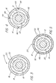
- FIG. 2 is an enlarged sectional view of the deployment device of FIG. 1 taken along line 2 - 2;
- FIG. 3 is an enlarged cross-sectional view of the deployment device of FIG 2 taken along line 3 - 3; 3;
- FIGS. 4 and 5 are cross-sectional views of further preferred embodiments of a stent deployment device of the present invention, similar to the view shown in FIG. 3;
- FIG. 6 is an enlarged side view of a portion of another preferred embodiment of the stent deployment device of the present invention;
- FIG. 7 is a side view of an enlarged portion of the preferred embodiment of the deployment device of FIG. 1 during use;
- FIG. 8 is a side view of another preferred embodiment of the present invention, similar to the view shown in F1G. 1;
- FIGS. 9A is a partial cross-sectional view of the deployment device of FIG. 8 taken along line 9A - 9A;
- FIG. 9B is a partial cross-sectional view of another preferred embodiment of the deployment device of the present invention, similar to the view shown in FIG. 9A;
- FIG. 10 is a partial cross-sectional view of the deployment device of FIG. 9B during use;
- FIG. 11A is a wide view of a portion of another example of deployment device not covered by the claims;
- FIG. 11 B is a side view of the deployment device of FIG. 11A during use;
- FIG. 12 is a cross-sectional view of a further preferred embodiment of the present invention, similar to the views shown in FIGS. 3 through 5;
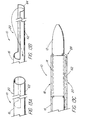
- FIGS. 13A and 13B are perspective views showing preliminary steps in constructing another example of deployment device not covered by the claims,
- FIG. 13C is a cross-sectional view of a portion of the device resulting from the steps shown in FIGS. 13A and 13B;
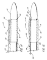
- FIG. 14 is a cross-sectional view of a portion of a still further example of deployment device, similar to the view shown in FIG. 13C, not covered by the claims;
- FIGS. 15A through 15C are partial cross-sectional views of additional examples of deployment devices, similar to the views shown in FIGS. 13C and 14, not covered by the claims; and
- FIG. 16 is a partial sectional side view of still yet another example of stent deployment device not covered by the claims.
- With reference first to FIGs. 1 through 3, a first preferred embodiment of the
stent deployment device 10 of the present invention is there shown, comprising acatheter 12, astent 14 positioned on thecatheter 12, and asleeve 16 carried on thecatheter 12. Thesleeve 16 has aportion 18 extending fully over and containing thestent 14. Thestent deployment device 10 further comprises amechanism 20 for splitting at least theportion 18 of thesleeve 16 extending over thestent 14. Actuation of themechanism 20 splits at least theportion 18 and permits expansion of thestent 14. - The
stent 14 can be self-expanding upon splitting of thesleeve portion 18, or can be expanded by thesplitting mechanism 20 itself. In either case, in this first embodiment of the present invention, thesplitting mechanism 20 comprises an inflatable,nondistending balloon 22 carried on thecatheter 12 near thedistal tip 26 of thecatheter 12. Thestent 14 and theportion 18 of thesleeve 16 extending over thestent 14 are thus positioned over theballoon 22, with thedistal end 28 of thesleeve 16 lying just distally of thestent 14. - One or more conventional
fluid couplings 32 are provided at theproximal end 30 of thecatheter 12, through which a pressurized fluid is supplied to theballoon 22 through a lumen for inflation. Inflation of the balloon with the fluid splits at least theportion 18 of thesleeve 16 extending over thestent 14, permitting expansion and deployment of thestent 14. Preferably, a this embodiment thestent 14 is expanded by expansion of theballoon 22 during its inflation by the fluid. Although not depicted, another lumen extends longitudinally through the catheter between the distal end thereof and one of theproximal couplings 32. This lumen is typically utilized for passing the catheter over a wire guide that has already been positioned in a vessel. - As indicated, the
stent 14 can be any type of implant, prosthesis or stent deliverable by catheter. Without limiting the scope of the invention, and only by way of example, in vascular applications thestent 14 can conveniently comprise the balloon-deliverable Palmaz or Gianturco stents described above. Thestent 14, of course, must survive any containment or compression by thesleeve portion 18 before theportion 18 is split, and must survive any compression experienced during splitting of thesleeve portion 18. Regardless of the specific construction of thestent 14 employed, the resulting expansion and deployment of thestent 14 is generally shown in FIG. 7. - In the first preferred embodiment of the
device 10, thesleeve 16 is substantially the same length as thecatheter 12 and includes aproximal end 38 fixed to thecatheter 12, for example, fixed near theproximal end 30 of thecatheter 12 at thecoupling 34. Alternatively, as shown in FIGs. 8 and 9A, thesleeve 16 can be much shorter in length than thecatheter 12, and can include aproximal end 40 fixed to thecatheter 12 close to thestent 14. - The
sleeve 16 can be composed of any of a variety of materials, some more suited to particular applications than others. Sound medical judgment should be employed in selecting the material for thesleeve 16. Thesleeve 16 should of course be composed of an indistensable material, so that thesleeve portion 18 is sure to split upon actuation of themechanism 20. Thesleeve 16 should also be composed of a medical grade material, which can be either physiologically inert or biodegradable. - Suitable inert materials for the
sleeve 16 include nylon, polyethylene, a polycaprolactam or polytetrafluoroethylene (PTFE). Nylon is preferred, especially in comparison to PTFE, since the latter can be subject to recoil after being drawn over thestent 14. If PTFE is employed, it may be advantageous to use scribed or molecular oriented PTFE, so as to facilitate splitting of thesleeve 16 orsleeve portion 18. - As shown in FIG. 12, a
lubricious surface 42 can be provided on thesleeve 16 to facilitate advancement of thedevice 10 through the vessel or the like into which thestent 14 is introduced. Thelubricious surface 42 can be formed by surface modification of thesleeve 16, for example, by ion beam bombardment or implantation, which is commercially available from Spire Corporation, Bedford, Mass. Alternatively, thelubricious surface 42 can comprise aseparate layer 44 of a hydrophilic material placed on thesleeve 16. - When the
sleeve 16 is composed of an inert material, splitting of thesleeve portion 18 or of thewhole sleeve 16 can be facilitated by the inclusion of a preferentially splittable, longitudinally extendingstructure 46 in at least thesleeve portion 18. The preferentiallysplittable structure 46 ensures that there will be at least one location at which thesleeve portion 18 readily splits. As shown in FIG. 4, the preferentiallysplittable structure 46 can comprise at least onearea 48, preferablyseveral areas 48, of reduced radial thickness.Such areas 48 can be formed by grooves, notches, scores, nicks or the like. Alternatively, as shown in FIG. 5, the preferentiallysplittable structure 46 can comprise splittable nylon such as, for example, a plurality of coextruded nylon strips 52 or plurality of adjacent strips of different material, which forms a tubular structure. This tubular structure forms thesleeve portion 18. As a result, thesleeve portion 18 will split betweenadjacent strips 52 upon actuation of thesplitting mechanism 20. As yet another alternative, as shown in FIG. 6 the preferentiallysplittable structure 46 can be formed as a spaced plurality of circumferentially offset perforations, such asslits 58, cut into at least thesleeve portion 18. - When either the
sleeve portion 18 or theentire sleeve 16 is composed of a biodegradable material, it is possible to allow part or all of the sleeve portion 1 8 to become severed from the remainder of thesleeve 16 and remain between thestent 14 and the wall of the vessel or the like in which thestent 14 is deployed. As shown in FIG. 9B, thesleeve 16 can include acircumferential groove 60 allowing such severing upon actuation of the splitting mechanism, that is, upon inflation of theballoon 22. The result is shown in FIG. 10. - A variety of biodegradable materials are expected to be useful for the
sleeve 16 orsleeve portion 18. Such materials include polyethylene, polypropylene and polyoxypropylene glycolic sugars, as well as polylactic sugars. The polylactic sugars are expected to degrade much more slowly than the glycolic sugars. The selection of a suitable material for a particular stent and application should be well within the sound medical judgment of those skilled in this area. - Again, it is not necessary, but merely preferred, that any
sleeve portion 18 left in the patient be biodegradable. The inert materials disclosed above are also suited to remain in the patient between the deployedstent 14 and the wall of the vessel or other site where thestent 14 is deployed. - In the embodiments disclosed above, the
sleeve 16 has been described as being fixed to thecatheter 12. In alternative preferred embodiments, however, thesleeve 16 need not be fixed to thecatheter 12, but rather can be slidable with respect to thecatheter 12 after thesleeve portion 18 has been split by thesplitting mechanism 20. Indeed, such sliding can make thesleeve 16 capable of being split along its entire length. In the following embodiments, this lack of affixment permits thecatheter 12 to be other than a balloon-type catheter. Self-expandingstents 14 are preferred for use in the following embodiments. - More particularly, as shown in FIGs. 11A and 11B, the
splitting mechanism 20, which does not fall within the scope of the claims, can comprise ameans 54 for splitting theentire sleeve 16 between its proximal end 38 (opposite the sleeve portion 18) and thesleeve portion 18. The splitting means 54 comprises a pair ofgraspable wings 56 on theproximal end 38 of thesleeve 16. "Wings" is a broad term, intended to be generic to a wide variety of graspable elements such as grips, flaps, tabs, ears and the like. Movement of thewings 56 in opposite directions (the unlabeled arrows in FIG. 11A) slits thesleeve 16 along its entire length, including theportion 18 extending over thestent 14, thereby withdrawing the pieces of thesleeve 16 from the patient and allowing deployment of thestent 14. - Alternatively, as shown in FIGs. 13A, 13B and 13C, the splitting means 54, which also does not fall within the scope of the claims, can comprise a
partial sleeve segment 62 folded back alongside the extending proximally of thestent 14. Thesleeve segment 62 includes a graspable,proximal end 64, allowing thesleeve segment 62 to be withdrawn, thereby splitting thesleeve 16. Scribed or molecular oriented PTFE is the preferred material for thesleeve 16 in this example. - In either of these examples of device, it is desirable to position the previously described
lubricious surface 42 on the inside of thesleeve 16, rather than on the outside of thesleeve 16, so as to reduce friction between thesleeve 16 and thecatheter 12. - Other examples achieve splitting of the
sleeve 16 orsleeve portion 18 in different ways. With reference to FIG. 14, for example, adevice 10, not falling within the scope of the claims, is shown in which thesplitting mechanism 20 comprises agarrote 66 having aproximal end 68 and adistal end 70. Thedistal end 70 of thegarrote 66 is connected to theinterior surface 72 of thesleeve 16, and thegarrote 66 extends first between thestent 14 and thesleeve 16, and then proximally of thestent 14. Withdrawal of theproximal end 68 of thegarrote 66 splits at least theportion 18 of thesleeve 16 extending over thestent 14. More of thesleeve 16 can be split, if desired, by fixing thedistal end 70 of thegarrote 66 to thesleeve 16 more proximally of thestent 14. - In still yet another example not falling within the scope of the claims, depicted in FIG. 16,
device 10 comprises asplittable sleeve 16 withsleeve portion 18 extending overstent 14.Proximal sleeve portion 18 includes side port oraperture 86 through which oneend 84 ofsuture 82 is passed from the exterior thereof intopassage 88 of the sleeve. This end is first passed throughpassage 88 and outdistal end 28 of the sleeve. The end of thesuture 82 is looped back via the exterior of the sheath and back intopassage 88 of the sleeve. Either one or both of proximal ends 84 of the suture are pulled with respective to the sleeve to split atleast sleeve portion 18. Whensleeve portion 18 is split up to side port oraperture 86, thestent 14 self expands or is expanded with a balloon as previously described. Furthermore,suture 82 can be completely withdrawn from the proximal end ofsleeve 16. - Several further but related embodiments of the
stent deployment device 10 of the present invention are shown in FIGs. 15A, 15B and 15C. In each, themechanism 20 for splitting thesleeve portion 18 is not necessarily aballoon 22, but rather preferably comprises abulbous end 24 on thecatheter 12. Thebulbous end 24 is preferably solid, to ensure that splitting of thesleeve 16 or thesleeve portion 18 occurs. However, thebulbous end 24 certainly could be an inflated or inflatable balloon. What is critical is that severing of thebulbous end 24 from thecatheter 12 must be avoided. - In any event, these embodiments differ from several of the other described embodiments in that the
stent 14 andsleeve portion 18 are not directly positioned over the splitting means 20 (for example, over the balloon 22). Rather, thestent 14 and thesleeve portion 18 are positioned proximally of thebulbous end 24, and it is longitudinal movement of thebulbous end 24 with respect to thesleeve 16 which splits at least thesleeve portion 18 and permits expansion of thestent 14. - These embodiments also differ from one another in the way in which the
stent 14 is positioned with respect to thesleeve portion 18. For example, in the embodiment shown in FIG. 15A, thestent 14 is simply received in the open end of thesleeve 16, and a long but relatively thin, lubriciousinner sheath 76 is positioned between thestent 14 and thecatheter 12, to reduce friction between thesleeve 16 and thecatheter 12, and thereby facilitate longitudinal movement of thecatheter 12 in the direction of the unlabeled arrow. Alternatively, as shown in FIG. 15B, theinner sheath 76 is omitted, and thestent 14 abutted against ashoulder 74 formed on the interior of thesleeve 16. Finally, as shown in FIG. 15C, thestent 14 is abutted against a relatively shorter, inner sheath orpusher 78, in place of theshoulder 74. The inner sheath orpusher 78 is slidable with respect the tosleeve 16. Which of these specific embodiments is most useful in a given situation is left to the sound discretion of the health care practitioner. - As indicated above, the last several embodiments of the
device 10 of the present invention need not include aballoon 22 on thecatheter 12. However, this is not to suggest that a balloon-type catheter 12 and balloon-expandable stent 14 could not be used in those embodiments. To the contrary, it should be clear that thebulbous catheter end 24 could itself be aballoon 22, longitudinally moved in the same way in order to split thesleeve portion 18. Unlike the earlier embodiments incorporating aballoon 22, thestent 14 andsleeve portion 18 are not positioned over theballoon 22, but spaced from it, like the solidbulbous end 24 described above. - Similarly, while it may be preferred to employ self-expanding stents in these embodiments of the present invention, it is certainly possible to employ a
stent 14 which is expanded by longitudinal movement of thebulbous catheter end 24 described above. - The methods of using the devices described above should now be evident. The
catheter 12 is first introduced to position thestent 14 at the location in a human or veterinary patient at which deployment of thestent 14 is desired. Thesplitting mechanism 20 is then actuated to split theportion 18 of thesleeve 16 over thestent 14, and expansion and deployment of thestent 14 are permitted to occur. As indicated, the stent can be self-expanding, or can be expanded by thesplitting mechanism 20 itself. In either case, thecatheter 12 and any desired portion of thesleeve 16 are withdrawn from the patient once thestent 14 is deployed. If thesleeve 16 is fixed to thecatheter 12, they are withdrawn together after the deflation of any balloon. If thesleeve 16 is not affixed to thecatheter 12, thesleeve 16 can be retracted while anyballoon 22 remains inflated, and thecatheter 12 withdrawn after deflation of theballoon 22. Anyballoon 22 is deflated, of course, by allowing the fluid in theballoon 22 to escape through thecatheter 12 and thecoupling 32. - The particular elements disclosed in regard to any single one of the embodiments described above may be readily adapted for use in others of the embodiments. For example, the preferentially
splittable structure 46 can be employed in any of the disclosed embodiments. Thelubricious surface 42 can be positioned in any location as is convenient or desired. Moreover, while all of the disclosed embodiments of the invention employstents 14 andsleeves 16 which encircle thecatheter 12 on which they are carried, the invention contemplates other arrangements for carrying astent 14 on acatheter 12. Theentire sleeve 16 can consist of only thesleeve portion 18 extending over thestent 14. Thecatheter 12 can, of course, include a lumen for a wire guide, or additional lumens for other purposes. Many other variations on the specific constructions of thecatheter 12, thestent 14 andsleeve 16 will be apparent to those skilled in this art, and all of such variations are contemplated within the scope of the present invention. - It should be clear from the foregoing that the present invention provides a stent deployment device which is highly advantageous over prior devices and methods of stent deployment. Initial splitting of the portion of the sleeve over the stent obviates the frictional resistance to withdrawal of the sleeve that would otherwise result from compression of the sleeve upon the stent. The substantial extent of the sleeve portion over the stent provides the device with good uniformity of resistance to kinking during use. Moreover, during use of many of the embodiments of the present invention, the stent is deployed rapidly, because no time is wasted in attempting to remove the sleeve from the patient before expansion of the stent occurs. If a balloon is employed on the catheter, the balloon is advantageously subjected to relatively uniform force during expansion, obviating any risk of damage to the balloon or stent during expansion. The device of the present invention is also advantageous in that its construction is straight-forward and relatively low in cost. Finally, since the device is introduced as a single unit, it is relatively easy to remove in case unexpected patient complications require interruption of the deployment procedure.
- Any undisclosed or incidental details of the construction or composition of the various elements of the disclosed embodiment of the present invention are not believed to be critical to the achievement of the advantages of the present invention, so long as the elements possess the characteristics needed for them to perform as disclosed. The selection of these and other details of construction are believed to be well within the ability of one of even rudimentary skills in this area, in view of the present disclosure.
- The present invention is useful in performing surgical procedures, and therefore finds applicability in human and veterinary medicine.
- It is to be understood, however, that the above-described device is merely an illustrative embodiment of the principles of this invention, and that other devices and methods for using them may be devised by those skilled in the art, without departing from the scope of the invention. It is also to be understood that the invention is directed to embodiments both comprising and consisting of the disclosed parts.
Claims (4)
- A stent deployment device (10) including a catheter (12), a stent (14) positioned on the catheter, a sleeve (16) on the catheter, the sleeve having a portion (18) extending over and containing the stent, and a mechanism (20) for splitting said at least portion of the sleeve, characterised in that the splitting mechanism is either: (a) an expandable balloon (22) within the stent and sleeve, the at least portion (18) of the sleeve (16) including a splittable, longitudinally extending structure (46) or a plurality of splittable material strips (52) and/or being severable from the remainder of the sleeve, or (b) a bulbous member on the catheter (24) longitudinally movable relative to the stent and sleeve; said splitting mechanism ensuring splitting of at least a portion of the sleeve on expansion of the balloon or on longitudinal movement of the bulbous member in the direction of the stent and sleeve to expand the stent or permitting a self expandable stent to expand.
- The device (10) according to claim 1, wherein the sleeve (16) is composed of polyamide such as nylon; polytetrafluoroethylene; polyethylene; a polycaprolactam; biodegradable material preferably polyethylene, polypropylene, or polyoxypropylene glycolic sugar, or a polylactic sugar.
- The device (10) according to claim 1 or 2, wherein the sleeve (16) includes a lubricious surface (42), the lubricious surface preferably comprising a layer (44) of a hydrophilic material or a surface modification of the sleeve.
- The device (10) according to claim 1, wherein the splittable structure (46) comprises at least one area (48) of reduced radial thickness.
Applications Claiming Priority (3)
| Application Number | Priority Date | Filing Date | Title |
|---|---|---|---|
| US3093796P | 1996-11-15 | 1996-11-15 | |
| US30937P | 1996-11-15 | ||
| PCT/US1997/020820 WO1998020812A1 (en) | 1996-11-15 | 1997-11-14 | Splittable sleeve, stent deployment device |
Publications (2)
| Publication Number | Publication Date |
|---|---|
| EP0952795A1 EP0952795A1 (en) | 1999-11-03 |
| EP0952795B1 true EP0952795B1 (en) | 2007-01-03 |
Family
ID=21856784
Family Applications (1)
| Application Number | Title | Priority Date | Filing Date |
|---|---|---|---|
| EP97947517A Expired - Lifetime EP0952795B1 (en) | 1996-11-15 | 1997-11-14 | Splittable sleeve, stent deployment device |
Country Status (7)
| Country | Link |
|---|---|
| US (1) | US6447540B1 (en) |
| EP (1) | EP0952795B1 (en) |
| JP (1) | JP2001504017A (en) |
| AU (1) | AU5257798A (en) |
| CA (1) | CA2271056A1 (en) |
| DE (1) | DE69737208T2 (en) |
| WO (1) | WO1998020812A1 (en) |
Families Citing this family (256)
| Publication number | Priority date | Publication date | Assignee | Title |
|---|---|---|---|---|
| US6352561B1 (en) * | 1996-12-23 | 2002-03-05 | W. L. Gore & Associates | Implant deployment apparatus |
| US6645138B2 (en) | 1997-09-12 | 2003-11-11 | Uromedica, Inc. | Adjustable implantable genitourinary device |
| US7364540B1 (en) | 1997-06-12 | 2008-04-29 | Uromedica, Inc. | Implantable device and method for adjustably restricting a body lumen |
| US6579224B1 (en) | 1999-10-11 | 2003-06-17 | Uromedica, Inc. | Apparatus and method for inserting an adjustable implantable genitourinary device |
| US6419624B1 (en) * | 1999-10-11 | 2002-07-16 | Uromedica, Inc. | Apparatus and method for inserting an adjustable implantable genitourinary device |
| US6045498A (en) | 1997-06-12 | 2000-04-04 | Uromedica, Inc. | Method for adjustably restricting a body lumen |
| US6176864B1 (en) * | 1998-03-09 | 2001-01-23 | Corvascular, Inc. | Anastomosis device and method |
| US6093194A (en) * | 1998-09-14 | 2000-07-25 | Endocare, Inc. | Insertion device for stents and methods for use |
| US6096027A (en) * | 1998-09-30 | 2000-08-01 | Impra, Inc., A Subsidiary Of C.R. Bard, Inc. | Bag enclosed stent loading apparatus |
| US6261316B1 (en) | 1999-03-11 | 2001-07-17 | Endologix, Inc. | Single puncture bifurcation graft deployment system |
| US8034100B2 (en) | 1999-03-11 | 2011-10-11 | Endologix, Inc. | Graft deployment system |
| AU4684500A (en) | 1999-04-30 | 2000-11-17 | Uromedica, Inc. | Method and apparatus for adjustable sling for treatment of urinary stress incontinence |
| DE19936207A1 (en) * | 1999-08-02 | 2001-02-15 | Angiomed Ag | Catheter and introducer with separator |
| DE19936980C1 (en) * | 1999-08-05 | 2001-04-26 | Aesculap Ag & Co Kg | Insertion catheter for vascular prostheses |
| US9579091B2 (en) | 2000-01-05 | 2017-02-28 | Integrated Vascular Systems, Inc. | Closure system and methods of use |
| US6461364B1 (en) | 2000-01-05 | 2002-10-08 | Integrated Vascular Systems, Inc. | Vascular sheath with bioabsorbable puncture site closure apparatus and methods of use |
| US6391048B1 (en) | 2000-01-05 | 2002-05-21 | Integrated Vascular Systems, Inc. | Integrated vascular device with puncture site closure component and sealant and methods of use |
| US7842068B2 (en) | 2000-12-07 | 2010-11-30 | Integrated Vascular Systems, Inc. | Apparatus and methods for providing tactile feedback while delivering a closure device |
| US8758400B2 (en) | 2000-01-05 | 2014-06-24 | Integrated Vascular Systems, Inc. | Closure system and methods of use |
| US6942674B2 (en) | 2000-01-05 | 2005-09-13 | Integrated Vascular Systems, Inc. | Apparatus and methods for delivering a closure device |
| US6391050B1 (en) | 2000-02-29 | 2002-05-21 | Scimed Life Systems, Inc. | Self-expanding stent delivery system |
| US6613067B1 (en) * | 2000-06-06 | 2003-09-02 | Scimed Life Systems, Inc. | Balloon protector |
| AU8800801A (en) | 2000-09-08 | 2002-03-22 | James E Coleman | Surgical staple |
| US6626918B1 (en) | 2000-10-06 | 2003-09-30 | Medical Technology Group | Apparatus and methods for positioning a vascular sheath |
| US6884257B1 (en) * | 2000-11-28 | 2005-04-26 | Advanced Cardiovascular Systems, Inc. | Stent delivery system with adjustable length balloon |
| US6623510B2 (en) | 2000-12-07 | 2003-09-23 | Integrated Vascular Systems, Inc. | Closure device and methods for making and using them |
| US8690910B2 (en) | 2000-12-07 | 2014-04-08 | Integrated Vascular Systems, Inc. | Closure device and methods for making and using them |
| US7806904B2 (en) | 2000-12-07 | 2010-10-05 | Integrated Vascular Systems, Inc. | Closure device |
| US7211101B2 (en) | 2000-12-07 | 2007-05-01 | Abbott Vascular Devices | Methods for manufacturing a clip and clip |
| US7905900B2 (en) | 2003-01-30 | 2011-03-15 | Integrated Vascular Systems, Inc. | Clip applier and methods of use |
| US6899727B2 (en) * | 2001-01-22 | 2005-05-31 | Gore Enterprise Holdings, Inc. | Deployment system for intraluminal devices |
| IES20010547A2 (en) | 2001-06-07 | 2002-12-11 | Christy Cummins | Surgical Staple |
| US7780693B2 (en) * | 2001-06-27 | 2010-08-24 | Salviac Limited | Catheter |
| US7789860B2 (en) * | 2001-06-27 | 2010-09-07 | Salviac Limited | Catheter for delivery and/or retrieval of a medical device |
| AU2002345328A1 (en) | 2001-06-27 | 2003-03-03 | Remon Medical Technologies Ltd. | Method and device for electrochemical formation of therapeutic species in vivo |
| SE524399C2 (en) * | 2001-09-07 | 2004-08-03 | Synergio Ag | A system for delivering a self-expanding medical device into a body vessel |
| DE10148185B4 (en) * | 2001-09-28 | 2005-08-11 | Alveolus, Inc. | Instrument for implanting vascular prostheses |
| DE10158289A1 (en) * | 2001-11-20 | 2003-05-28 | Biotronik Mess & Therapieg | Device for implanting catheters |
| US6749621B2 (en) * | 2002-02-21 | 2004-06-15 | Integrated Vascular Systems, Inc. | Sheath apparatus and methods for delivering a closure device |
| US20030181810A1 (en) * | 2002-03-25 | 2003-09-25 | Murphy Kieran P. | Kit for image guided surgical procedures |
| US9375203B2 (en) | 2002-03-25 | 2016-06-28 | Kieran Murphy Llc | Biopsy needle |
| US7927368B2 (en) | 2002-03-25 | 2011-04-19 | Kieran Murphy Llc | Device viewable under an imaging beam |
| US20030204248A1 (en) * | 2002-03-25 | 2003-10-30 | Murphy Kieran P. | Device viewable under an imaging beam |
| WO2003101347A1 (en) | 2002-05-31 | 2003-12-11 | Wilson-Cook Medical Inc. | Stent introducer apparatus |
| DE60325355D1 (en) | 2002-06-04 | 2009-01-29 | Abbott Vascular Inc | SURGICAL CLOSURE AND MOUNTING DEVICE FOR VASCULAR SEALING |
| US7048719B1 (en) | 2002-06-07 | 2006-05-23 | Microvention, Inc. | Endovascular catheter resheathing apparatus and related methods |
| US6793678B2 (en) | 2002-06-27 | 2004-09-21 | Depuy Acromed, Inc. | Prosthetic intervertebral motion disc having dampening |
| US7329268B2 (en) * | 2002-07-02 | 2008-02-12 | Warsaw Orthopedic, Inc. | Expandable percutaneous sheath |
| US20040015224A1 (en) * | 2002-07-22 | 2004-01-22 | Armstrong Joseph R. | Endoluminal expansion system |
| WO2004027576A2 (en) * | 2002-09-18 | 2004-04-01 | Netezza Corporation | Asymmetric data streaming architecture having autonomous and asynchronous job processing unit |
| US6673101B1 (en) * | 2002-10-09 | 2004-01-06 | Endovascular Technologies, Inc. | Apparatus and method for deploying self-expanding stents |
| JP2006507841A (en) * | 2002-11-14 | 2006-03-09 | ダーマコン, インコーポレイテッド | Functional and ultrafunctional siRNA |
| ES2562024T3 (en) * | 2002-11-26 | 2016-03-02 | Endologix, Inc. | Graft deployment system |
| US7198636B2 (en) * | 2003-01-17 | 2007-04-03 | Gore Enterprise Holdings, Inc. | Deployment system for an endoluminal device |
| AU2007237298B2 (en) * | 2003-01-17 | 2010-07-01 | W. L. Gore & Associates, Inc. | Deployment system for an endoluminal device |
| US7753945B2 (en) * | 2003-01-17 | 2010-07-13 | Gore Enterprise Holdings, Inc. | Deployment system for an endoluminal device |
| US20060058866A1 (en) | 2003-01-17 | 2006-03-16 | Cully Edward H | Deployment system for an expandable device |
| US9433745B2 (en) * | 2003-01-17 | 2016-09-06 | W.L. Gore & Associates, Inc. | Puncturing tool for puncturing catheter shafts |
| US8016752B2 (en) * | 2003-01-17 | 2011-09-13 | Gore Enterprise Holdings, Inc. | Puncturable catheter |
| US20040143240A1 (en) * | 2003-01-17 | 2004-07-22 | Armstrong Joseph R. | Adjustable length catheter |
| US7625337B2 (en) * | 2003-01-17 | 2009-12-01 | Gore Enterprise Holdings, Inc. | Catheter assembly |
| US8758398B2 (en) | 2006-09-08 | 2014-06-24 | Integrated Vascular Systems, Inc. | Apparatus and method for delivering a closure element |
| US8202293B2 (en) | 2003-01-30 | 2012-06-19 | Integrated Vascular Systems, Inc. | Clip applier and methods of use |
| US8905937B2 (en) | 2009-02-26 | 2014-12-09 | Integrated Vascular Systems, Inc. | Methods and apparatus for locating a surface of a body lumen |
| US8821534B2 (en) | 2010-12-06 | 2014-09-02 | Integrated Vascular Systems, Inc. | Clip applier having improved hemostasis and methods of use |
| US7857828B2 (en) | 2003-01-30 | 2010-12-28 | Integrated Vascular Systems, Inc. | Clip applier and methods of use |
| US8398656B2 (en) | 2003-01-30 | 2013-03-19 | Integrated Vascular Systems, Inc. | Clip applier and methods of use |
| US20040172055A1 (en) * | 2003-02-27 | 2004-09-02 | Huter Scott J. | Embolic filtering devices |
| US7655021B2 (en) * | 2003-03-10 | 2010-02-02 | Boston Scientific Scimed, Inc. | Dilator with expandable member |
| US20050049672A1 (en) * | 2003-03-24 | 2005-03-03 | Murphy Kieran P. | Stent delivery system and method using a balloon for a self-expandable stent |
| US20040193179A1 (en) | 2003-03-26 | 2004-09-30 | Cardiomind, Inc. | Balloon catheter lumen based stent delivery systems |
| JP2006521161A (en) | 2003-03-26 | 2006-09-21 | カーディオマインド インコーポレイティッド | Implant delivery technology |
| US7771463B2 (en) | 2003-03-26 | 2010-08-10 | Ton Dai T | Twist-down implant delivery technologies |
| US7060038B2 (en) | 2003-04-24 | 2006-06-13 | Medtronic Vascular, Inc. | Device for delivering a sensor to the endovascular system and method of use |
| US7604660B2 (en) * | 2003-05-01 | 2009-10-20 | Merit Medical Systems, Inc. | Bifurcated medical appliance delivery apparatus and method |
| EP1660165B1 (en) * | 2003-07-31 | 2008-06-04 | Wilson-Cook Medical Inc. | System for introducing multiple medical devices |
| US8211087B2 (en) * | 2003-07-31 | 2012-07-03 | Cook Medical Technologies Llc | Distal wire stop |
| WO2005013855A2 (en) * | 2003-08-01 | 2005-02-17 | Cook Urological, Incorporated | Implant delivery device |
| US20080033570A1 (en) * | 2003-08-01 | 2008-02-07 | Blitz Benjamin T | Prostatic stent placement device |
| US7699865B2 (en) | 2003-09-12 | 2010-04-20 | Rubicon Medical, Inc. | Actuating constraining mechanism |
| US8535344B2 (en) | 2003-09-12 | 2013-09-17 | Rubicon Medical, Inc. | Methods, systems, and devices for providing embolic protection and removing embolic material |
| US7488343B2 (en) | 2003-09-16 | 2009-02-10 | Boston Scientific Scimed, Inc. | Medical devices |
| US7645296B2 (en) * | 2003-10-16 | 2010-01-12 | Minvasys | Catheter system for protected angioplasty and stenting at a carotid bifurcation |
| US7338509B2 (en) * | 2003-11-06 | 2008-03-04 | Boston Scientific Scimed, Inc. | Electroactive polymer actuated sheath for implantable or insertable medical device |
| US7780692B2 (en) | 2003-12-05 | 2010-08-24 | Onset Medical Corporation | Expandable percutaneous sheath |
| US9241735B2 (en) | 2003-12-05 | 2016-01-26 | Onset Medical Corporation | Expandable percutaneous sheath |
| US9254213B2 (en) * | 2004-01-09 | 2016-02-09 | Rubicon Medical, Inc. | Stent delivery device |
| US7972350B2 (en) * | 2004-01-29 | 2011-07-05 | Boston Scientific Scimed, Inc. | Catheter tip |
| US8137397B2 (en) * | 2004-02-26 | 2012-03-20 | Boston Scientific Scimed, Inc. | Medical devices |
| US7651521B2 (en) | 2004-03-02 | 2010-01-26 | Cardiomind, Inc. | Corewire actuated delivery system with fixed distal stent-carrying extension |
| US20050273150A1 (en) | 2004-03-31 | 2005-12-08 | Howell Douglas D | Stent introducer system |
| US7232462B2 (en) * | 2004-03-31 | 2007-06-19 | Cook Incorporated | Self centering delivery catheter |
| ATE491416T1 (en) * | 2004-03-31 | 2011-01-15 | Cook Inc | STENT DEPOSITION DEVICE |
| US20060041270A1 (en) * | 2004-05-07 | 2006-02-23 | Jay Lenker | Medical access sheath |
| IES20040368A2 (en) | 2004-05-25 | 2005-11-30 | James E Coleman | Surgical stapler |
| WO2005118019A1 (en) * | 2004-05-28 | 2005-12-15 | Cook Incorporated | Implantable bioabsorbable valve support frame |
| US8308789B2 (en) | 2004-07-16 | 2012-11-13 | W. L. Gore & Associates, Inc. | Deployment system for intraluminal devices |
| EP1771221B1 (en) * | 2004-07-29 | 2010-09-22 | Wilson-Cook Medical Inc. | Catheter with splittable wall shaft |
| US9387313B2 (en) | 2004-08-03 | 2016-07-12 | Interventional Spine, Inc. | Telescopic percutaneous tissue dilation systems and related methods |
| EP1819391B1 (en) | 2004-09-09 | 2020-02-19 | Onset Medical Corporation | Expandable transluminal sheath |
| US20060135962A1 (en) | 2004-09-09 | 2006-06-22 | Kick George F | Expandable trans-septal sheath |
| US7892203B2 (en) | 2004-09-09 | 2011-02-22 | Onset Medical Corporation | Expandable transluminal sheath |
| US7699862B2 (en) * | 2005-01-25 | 2010-04-20 | Micrus Corporation | Resheathing tool |
| US20060212106A1 (en) * | 2005-03-21 | 2006-09-21 | Jan Weber | Coatings for use on medical devices |
| US20060259061A1 (en) * | 2005-04-22 | 2006-11-16 | Kick George F | Expandable sheath for percutaneous upper gastrointestinal tract access |
| US8092481B2 (en) * | 2005-06-03 | 2012-01-10 | Onset Medical Corporation | Expandable percutaneous sheath |
| US20070027522A1 (en) * | 2005-06-14 | 2007-02-01 | Chang Jean C | Stent delivery and guidewire systems |
| EP1893125B1 (en) | 2005-06-20 | 2018-09-26 | Cook Medical Technologies LLC | Single peel stent introducer apparatus |
| US8926633B2 (en) | 2005-06-24 | 2015-01-06 | Abbott Laboratories | Apparatus and method for delivering a closure element |
| US8313497B2 (en) | 2005-07-01 | 2012-11-20 | Abbott Laboratories | Clip applier and methods of use |
| JP2007037971A (en) * | 2005-07-05 | 2007-02-15 | Ookiddo:Kk | Catheter assembly and sheath tearing assist |
| US8920442B2 (en) | 2005-08-24 | 2014-12-30 | Abbott Vascular Inc. | Vascular opening edge eversion methods and apparatuses |
| US9456811B2 (en) | 2005-08-24 | 2016-10-04 | Abbott Vascular Inc. | Vascular closure methods and apparatuses |
| US20070060895A1 (en) | 2005-08-24 | 2007-03-15 | Sibbitt Wilmer L Jr | Vascular closure methods and apparatuses |
| IL170698A (en) * | 2005-09-06 | 2011-11-30 | Allium Ltd | System for delivering a medical device to a body location |
| US20070100414A1 (en) | 2005-11-02 | 2007-05-03 | Cardiomind, Inc. | Indirect-release electrolytic implant delivery systems |
| US8840660B2 (en) | 2006-01-05 | 2014-09-23 | Boston Scientific Scimed, Inc. | Bioerodible endoprostheses and methods of making the same |
| US8089029B2 (en) | 2006-02-01 | 2012-01-03 | Boston Scientific Scimed, Inc. | Bioabsorbable metal medical device and method of manufacture |
| US7648527B2 (en) * | 2006-03-01 | 2010-01-19 | Cook Incorporated | Methods of reducing retrograde flow |
| US20070208408A1 (en) * | 2006-03-06 | 2007-09-06 | Boston Scientific Scimed, Inc. | Non-foreshortening sheaths and assemblies for use |
| EP1836998B1 (en) * | 2006-03-24 | 2010-02-24 | Cordis Corporation | Split sheath delivery system for self expanding stents |
| US8048150B2 (en) | 2006-04-12 | 2011-11-01 | Boston Scientific Scimed, Inc. | Endoprosthesis having a fiber meshwork disposed thereon |
| US8808310B2 (en) | 2006-04-20 | 2014-08-19 | Integrated Vascular Systems, Inc. | Resettable clip applier and reset tools |
| US8556930B2 (en) | 2006-06-28 | 2013-10-15 | Abbott Laboratories | Vessel closure device |
| DE102006033399B4 (en) * | 2006-07-19 | 2009-04-09 | Jotec Gmbh | Marker system and delivery system for such a marker system |
| JP2009545407A (en) | 2006-08-02 | 2009-12-24 | ボストン サイエンティフィック サイムド,インコーポレイテッド | End prosthesis with 3D decomposition control |
| JP2010503485A (en) | 2006-09-15 | 2010-02-04 | ボストン サイエンティフィック リミテッド | Medical device and method for manufacturing the same |
| ATE517590T1 (en) | 2006-09-15 | 2011-08-15 | Boston Scient Ltd | BIOLOGICALLY ERODABLE ENDOPROTHESES |
| ES2368125T3 (en) | 2006-09-15 | 2011-11-14 | Boston Scientific Scimed, Inc. | BIOEROSIONABLE ENDOPROOTHESIS WITH BIOESTABLE INORGANIC LAYERS. |
| US8808726B2 (en) | 2006-09-15 | 2014-08-19 | Boston Scientific Scimed. Inc. | Bioerodible endoprostheses and methods of making the same |
| JP2010503490A (en) | 2006-09-15 | 2010-02-04 | ボストン サイエンティフィック リミテッド | Endoprosthesis with adjustable surface features |
| US8002821B2 (en) | 2006-09-18 | 2011-08-23 | Boston Scientific Scimed, Inc. | Bioerodible metallic ENDOPROSTHESES |
| WO2008070863A2 (en) | 2006-12-07 | 2008-06-12 | Interventional Spine, Inc. | Intervertebral implant |
| US8337518B2 (en) | 2006-12-20 | 2012-12-25 | Onset Medical Corporation | Expandable trans-septal sheath |
| ATE488259T1 (en) | 2006-12-28 | 2010-12-15 | Boston Scient Ltd | BIOERODIBLE ENDOPROTHES AND PRODUCTION METHODS THEREOF |
| US8764816B2 (en) * | 2007-05-07 | 2014-07-01 | W. L. Gore & Associates, Inc. | Stent delivery and deployment system |
| US8226681B2 (en) | 2007-06-25 | 2012-07-24 | Abbott Laboratories | Methods, devices, and apparatus for managing access through tissue |
| US8900307B2 (en) | 2007-06-26 | 2014-12-02 | DePuy Synthes Products, LLC | Highly lordosed fusion cage |
| US8292872B2 (en) * | 2007-06-29 | 2012-10-23 | Cook Medical Technologies Llc | Distal wire stop having adjustable handle |
| US8052745B2 (en) | 2007-09-13 | 2011-11-08 | Boston Scientific Scimed, Inc. | Endoprosthesis |
| JP5398971B2 (en) * | 2007-10-01 | 2014-01-29 | オリンパスメディカルシステムズ株式会社 | Stent placement device |
| US8795326B2 (en) | 2007-10-05 | 2014-08-05 | Covidien Lp | Expanding seal anchor for single incision surgery |
| CA2701576C (en) | 2007-10-17 | 2016-06-21 | Angiomed Gmbh & Co. Medizintechnik Kg | Delivery system for a self-expanding device for placement in a bodily lumen |
| EP3459572A1 (en) | 2007-11-14 | 2019-03-27 | Biosensors International Group, Ltd. | Automated coating method |
| JP5377944B2 (en) * | 2007-11-30 | 2013-12-25 | 住友ベークライト株式会社 | Gastrostomy sheath, sheathed dilator, gastrostomy sheath with insertion aid, gastrostomy catheter kit |
| US8893947B2 (en) | 2007-12-17 | 2014-11-25 | Abbott Laboratories | Clip applier and methods of use |
| US20090157101A1 (en) | 2007-12-17 | 2009-06-18 | Abbott Laboratories | Tissue closure system and methods of use |
| US7841502B2 (en) | 2007-12-18 | 2010-11-30 | Abbott Laboratories | Modular clip applier |
| US8845712B2 (en) * | 2008-01-15 | 2014-09-30 | W. L. Gore & Associates, Inc. | Pleated deployment sheath |
| CN101909548B (en) | 2008-01-17 | 2014-07-30 | 斯恩蒂斯有限公司 | An expandable intervertebral implant and associated method of manufacturing the same |
| WO2009105699A1 (en) | 2008-02-22 | 2009-08-27 | Endologix, Inc. | Design and method of placement of a graft or graft system |
| JP5441997B2 (en) | 2008-04-05 | 2014-03-12 | ジンテス ゲゼルシャフト ミット ベシュレンクテル ハフツング | Expandable intervertebral implant |
| US8236040B2 (en) | 2008-04-11 | 2012-08-07 | Endologix, Inc. | Bifurcated graft deployment systems and methods |
| US7998192B2 (en) | 2008-05-09 | 2011-08-16 | Boston Scientific Scimed, Inc. | Endoprostheses |
| CA2720466A1 (en) * | 2008-05-09 | 2009-11-12 | Juergen Dorn | Method of loading a stent into a sheath |
| GB0815339D0 (en) * | 2008-08-21 | 2008-10-01 | Angiomed Ag | Method of loading a stent into a sheath |
| US9282965B2 (en) | 2008-05-16 | 2016-03-15 | Abbott Laboratories | Apparatus and methods for engaging tissue |
| US8236046B2 (en) | 2008-06-10 | 2012-08-07 | Boston Scientific Scimed, Inc. | Bioerodible endoprosthesis |
| EP2293838B1 (en) | 2008-07-01 | 2012-08-08 | Endologix, Inc. | Catheter system |
| US7985252B2 (en) | 2008-07-30 | 2011-07-26 | Boston Scientific Scimed, Inc. | Bioerodible endoprosthesis |
| US8382824B2 (en) | 2008-10-03 | 2013-02-26 | Boston Scientific Scimed, Inc. | Medical implant having NANO-crystal grains with barrier layers of metal nitrides or fluorides |
| US8398676B2 (en) | 2008-10-30 | 2013-03-19 | Abbott Vascular Inc. | Closure device |
| KR20110102422A (en) * | 2008-12-10 | 2011-09-16 | 마이크로벤션, 인코포레이티드 | Microcatheter |
| US8444669B2 (en) | 2008-12-15 | 2013-05-21 | Boston Scientific Scimed, Inc. | Embolic filter delivery system and method |
| US8858594B2 (en) | 2008-12-22 | 2014-10-14 | Abbott Laboratories | Curved closure device |
| US8323312B2 (en) | 2008-12-22 | 2012-12-04 | Abbott Laboratories | Closure device |
| GB0823716D0 (en) | 2008-12-31 | 2009-02-04 | Angiomed Ag | Stent delivery device with rolling stent retaining sheath |
| US9089311B2 (en) | 2009-01-09 | 2015-07-28 | Abbott Vascular Inc. | Vessel closure devices and methods |
| US9173644B2 (en) | 2009-01-09 | 2015-11-03 | Abbott Vascular Inc. | Closure devices, systems, and methods |
| US20100179589A1 (en) | 2009-01-09 | 2010-07-15 | Abbott Vascular Inc. | Rapidly eroding anchor |
| US9414820B2 (en) | 2009-01-09 | 2016-08-16 | Abbott Vascular Inc. | Closure devices, systems, and methods |
| US9486191B2 (en) | 2009-01-09 | 2016-11-08 | Abbott Vascular, Inc. | Closure devices |
| US20100185234A1 (en) | 2009-01-16 | 2010-07-22 | Abbott Vascular Inc. | Closure devices, systems, and methods |
| EP2403546A2 (en) | 2009-03-02 | 2012-01-11 | Boston Scientific Scimed, Inc. | Self-buffering medical implants |
| US9526620B2 (en) | 2009-03-30 | 2016-12-27 | DePuy Synthes Products, Inc. | Zero profile spinal fusion cage |
| US9326874B2 (en) | 2009-04-15 | 2016-05-03 | Cook Medical Technologies Llc | Introducer apparatus |
| EP2429452B1 (en) | 2009-04-28 | 2020-01-15 | Endologix, Inc. | Endoluminal prosthesis system |
| US8657870B2 (en) | 2009-06-26 | 2014-02-25 | Biosensors International Group, Ltd. | Implant delivery apparatus and methods with electrolytic release |
| US8936634B2 (en) | 2009-07-15 | 2015-01-20 | W. L. Gore & Associates, Inc. | Self constraining radially expandable medical devices |
| US8435282B2 (en) | 2009-07-15 | 2013-05-07 | W. L. Gore & Associates, Inc. | Tube with reverse necking properties |
| US20110054492A1 (en) | 2009-08-26 | 2011-03-03 | Abbott Laboratories | Medical device for repairing a fistula |
| CN102639086A (en) * | 2009-09-10 | 2012-08-15 | 挪威斯腾特公司 | Vascular prosthesis assembly with retention mechanism and method |
| US8366765B2 (en) * | 2009-09-18 | 2013-02-05 | Medtronic Vascular, Inc. | Helical stent with connections |
| GB0921237D0 (en) | 2009-12-03 | 2010-01-20 | Angiomed Ag | Stent device delivery system and method of making such |
| GB0921238D0 (en) | 2009-12-03 | 2010-01-20 | Angiomed Ag | Stent device delivery system and method of making such |
| GB0921240D0 (en) | 2009-12-03 | 2010-01-20 | Angiomed Ag | Stent device delivery system and method of making such |
| GB0921236D0 (en) * | 2009-12-03 | 2010-01-20 | Angiomed Ag | Stent device delivery system and method of making such |
| US9393129B2 (en) | 2009-12-10 | 2016-07-19 | DePuy Synthes Products, Inc. | Bellows-like expandable interbody fusion cage |
| US20110218615A1 (en) * | 2010-03-02 | 2011-09-08 | Medtronic Vascular, Inc. | Stent With Multi-Crown Constraint and Method for Ending Helical Wound Stents |
| US8206434B2 (en) | 2010-03-02 | 2012-06-26 | Medtronic Vascular, Inc. | Stent with sinusoidal wave form and orthogonal end and method for making same |
| US8303624B2 (en) | 2010-03-15 | 2012-11-06 | Abbott Cardiovascular Systems, Inc. | Bioabsorbable plug |
| US8668732B2 (en) | 2010-03-23 | 2014-03-11 | Boston Scientific Scimed, Inc. | Surface treated bioerodible metal endoprostheses |
| US9282979B2 (en) | 2010-06-24 | 2016-03-15 | DePuy Synthes Products, Inc. | Instruments and methods for non-parallel disc space preparation |
| US8979860B2 (en) | 2010-06-24 | 2015-03-17 | DePuy Synthes Products. LLC | Enhanced cage insertion device |
| GB201010766D0 (en) * | 2010-06-25 | 2010-08-11 | Angiomed Ag | Delivery system for a self-expanding implant |
| WO2012003175A1 (en) | 2010-06-29 | 2012-01-05 | Synthes Usa, Llc | Distractible intervertebral implant |
| US8328072B2 (en) | 2010-07-19 | 2012-12-11 | Medtronic Vascular, Inc. | Method for forming a wave form used to make wound stents |
| US8758399B2 (en) | 2010-08-02 | 2014-06-24 | Abbott Cardiovascular Systems, Inc. | Expandable bioabsorbable plug apparatus and method |
| US8603116B2 (en) | 2010-08-04 | 2013-12-10 | Abbott Cardiovascular Systems, Inc. | Closure device with long tines |
| US9402732B2 (en) | 2010-10-11 | 2016-08-02 | DePuy Synthes Products, Inc. | Expandable interspinous process spacer implant |
| EP2635241B1 (en) | 2010-11-02 | 2019-02-20 | Endologix, Inc. | Apparatus for placement of a graft or graft system |
| US9675487B2 (en) | 2010-11-17 | 2017-06-13 | Cook Medical Technologies Llc | Prosthesis deployment system for vascular repair |
| GB201020373D0 (en) * | 2010-12-01 | 2011-01-12 | Angiomed Ag | Device to release a self-expanding implant |
| US8657866B2 (en) | 2010-12-22 | 2014-02-25 | Cook Medical Technologies Llc | Emergency vascular repair prosthesis deployment system |
| US8617184B2 (en) | 2011-02-15 | 2013-12-31 | Abbott Cardiovascular Systems, Inc. | Vessel closure system |
| JP6066931B2 (en) | 2011-02-25 | 2017-01-25 | マイクロベンション インコーポレイテッド | Reinforced balloon catheter |
| WO2012118901A1 (en) | 2011-03-01 | 2012-09-07 | Endologix, Inc. | Catheter system and methods of using same |
| US9149276B2 (en) | 2011-03-21 | 2015-10-06 | Abbott Cardiovascular Systems, Inc. | Clip and deployment apparatus for tissue closure |
| US10058442B2 (en) * | 2011-04-08 | 2018-08-28 | W. L. Gore & Associates, Inc. | Endoprosthesis delivery system |
| US8852257B2 (en) * | 2011-06-21 | 2014-10-07 | Abbott Cardiovascular Systems Inc. | Sheaths used with polymer scaffold |
| US9296034B2 (en) | 2011-07-26 | 2016-03-29 | Medtronic Vascular, Inc. | Apparatus and method for forming a wave form for a stent from a wire |
| US9011514B2 (en) | 2011-08-22 | 2015-04-21 | Cook Medical Technologies Llc | Emergency vessel repair prosthesis deployment system |
| US9332976B2 (en) | 2011-11-30 | 2016-05-10 | Abbott Cardiovascular Systems, Inc. | Tissue closure device |
| US9242290B2 (en) | 2012-04-03 | 2016-01-26 | Medtronic Vascular, Inc. | Method and apparatus for creating formed elements used to make wound stents |
| US9238260B2 (en) | 2012-04-18 | 2016-01-19 | Medtronic Vascular, Inc. | Method and apparatus for creating formed elements used to make wound stents |
| US9364351B2 (en) | 2012-04-23 | 2016-06-14 | Medtronic Vascular, Inc. | Method for forming a stent |
| US8940052B2 (en) | 2012-07-26 | 2015-01-27 | DePuy Synthes Products, LLC | Expandable implant |
| US20140067069A1 (en) | 2012-08-30 | 2014-03-06 | Interventional Spine, Inc. | Artificial disc |
| US10173038B2 (en) * | 2012-09-05 | 2019-01-08 | W. L. Gore & Associates, Inc. | Retractable sheath devices, systems, and methods |
| US9072590B2 (en) | 2012-12-07 | 2015-07-07 | Abbott Cardiovascular Systems Inc. | Sheaths reducing recoil and loss of retention for polymer scaffolds crimped to balloons |
| US9364209B2 (en) | 2012-12-21 | 2016-06-14 | Abbott Cardiovascular Systems, Inc. | Articulating suturing device |
| US9522070B2 (en) | 2013-03-07 | 2016-12-20 | Interventional Spine, Inc. | Intervertebral implant |
| JP2016516552A (en) | 2013-05-03 | 2016-06-09 | シー・アール・バード・インコーポレーテッドC R Bard Incorporated | Protective sheath that can be peeled off |
| US9788983B2 (en) | 2013-06-21 | 2017-10-17 | Abbott Cardiovascular Systems Inc. | Removable sheath assembly for a polymer scaffold |
| US9675483B2 (en) | 2013-06-21 | 2017-06-13 | Abbott Cardiovascular Systems Inc. | Protective sheath assembly for a polymer scaffold |
| US10098771B2 (en) | 2013-09-25 | 2018-10-16 | Abbott Cardiovascular Systems Inc. | Clip sheath for a polymer scaffold |
| US9913958B2 (en) | 2014-02-28 | 2018-03-13 | Abbott Cardiovascular Systems Inc. | Protective sheaths for medical devices |
| US9364361B2 (en) | 2014-03-13 | 2016-06-14 | Abbott Cardiovascular Systems Inc. | Striped sheaths for medical devices |
| WO2015148478A1 (en) * | 2014-03-24 | 2015-10-01 | Georgia Tech Research Corporation | Splittable needle |
| GB2525031A (en) | 2014-04-10 | 2015-10-14 | Cook Medical Technologies Llc | Introducer assembly and protective sleeve therefor |
| WO2015171911A1 (en) * | 2014-05-09 | 2015-11-12 | Mayo Foundation For Medical Education And Research | Devices and methods for forming stents in vivo |
| US10569063B2 (en) | 2014-10-03 | 2020-02-25 | W. L. Gore & Associates, Inc. | Removable covers for drug eluting medical devices |
| US10322269B1 (en) | 2015-01-19 | 2019-06-18 | Dalent, LLC | Dilator device |
| US11426290B2 (en) | 2015-03-06 | 2022-08-30 | DePuy Synthes Products, Inc. | Expandable intervertebral implant, system, kit and method |
| WO2017004265A1 (en) | 2015-06-30 | 2017-01-05 | Endologix, Inc. | Locking assembly for coupling guidewire to delivery system |
| US9913727B2 (en) | 2015-07-02 | 2018-03-13 | Medos International Sarl | Expandable implant |
| US10596330B2 (en) | 2015-08-26 | 2020-03-24 | Medtronic Xomed, Inc. | Resorbable, drug-eluting submucosal turbinate implant device and method |
| GB2550938B (en) | 2016-06-01 | 2018-07-11 | Cook Medical Technologies Llc | Medical device introducer assembly particularly for branched medical devices |
| US11510788B2 (en) | 2016-06-28 | 2022-11-29 | Eit Emerging Implant Technologies Gmbh | Expandable, angularly adjustable intervertebral cages |
| WO2018002715A2 (en) | 2016-06-28 | 2018-01-04 | Eit Emerging Implant Technologies Gmbh | Expandable and angularly adjustable articulating intervertebral cages |
| US10537436B2 (en) | 2016-11-01 | 2020-01-21 | DePuy Synthes Products, Inc. | Curved expandable cage |
| US10888433B2 (en) | 2016-12-14 | 2021-01-12 | DePuy Synthes Products, Inc. | Intervertebral implant inserter and related methods |
| US10398563B2 (en) | 2017-05-08 | 2019-09-03 | Medos International Sarl | Expandable cage |
| US11344424B2 (en) | 2017-06-14 | 2022-05-31 | Medos International Sarl | Expandable intervertebral implant and related methods |
| US10940016B2 (en) | 2017-07-05 | 2021-03-09 | Medos International Sarl | Expandable intervertebral fusion cage |
| WO2020028022A1 (en) | 2018-08-03 | 2020-02-06 | The Johns Hopkins University | Lacrimal canalicular delivery system and methods of use |
| US11389627B1 (en) | 2018-10-02 | 2022-07-19 | Lutonix Inc. | Balloon protectors, balloon-catheter assemblies, and methods thereof |
| US11446156B2 (en) | 2018-10-25 | 2022-09-20 | Medos International Sarl | Expandable intervertebral implant, inserter instrument, and related methods |
| WO2020102320A2 (en) * | 2018-11-14 | 2020-05-22 | Medtronic Inc. | Devices and methods for preparing a valve for a transcatheter valve replacement procedure |
| US11510766B2 (en) | 2019-02-14 | 2022-11-29 | Uromedica, Inc. | Method and apparatus for monitoring implantable device for urinary continence |
| USD877325S1 (en) | 2019-06-06 | 2020-03-03 | Dalent, LLC | Inflatable therapeutic treatment balloon device |
| US11426286B2 (en) | 2020-03-06 | 2022-08-30 | Eit Emerging Implant Technologies Gmbh | Expandable intervertebral implant |
| CN114710951A (en) | 2020-10-29 | 2022-07-05 | 安吉美德医疗技术有限公司 | Vascular occlusion device and method of occluding a vascular access orifice using the same |
| US11850160B2 (en) | 2021-03-26 | 2023-12-26 | Medos International Sarl | Expandable lordotic intervertebral fusion cage |
| US11752009B2 (en) | 2021-04-06 | 2023-09-12 | Medos International Sarl | Expandable intervertebral fusion cage |
| DE102022127775A1 (en) | 2022-10-20 | 2024-04-25 | Rheinisch-Westfälische Technische Hochschule Aachen, abgekürzt RWTH Aachen, Körperschaft des öffentlichen Rechts | Cannula arrangement |
Family Cites Families (35)
| Publication number | Priority date | Publication date | Assignee | Title |
|---|---|---|---|---|
| BE789131A (en) | 1971-09-24 | 1973-03-22 | Extracorporeal Med Spec | SURGICAL NEEDLE FOR PERFORMING MEDICAL OPERATIONS |
| US3877429A (en) | 1973-11-30 | 1975-04-15 | David L Rasumoff | Catheter placement device |
| US4027659A (en) | 1975-11-21 | 1977-06-07 | Krandex Corporation | Radiographic opaque and conductive stripped medical tubes |
| US4182582A (en) | 1976-01-27 | 1980-01-08 | A. T. Ramot Plastics Ltd. | Porous tubes and hollow profile structures and method of making same |
| US4166469A (en) | 1977-12-13 | 1979-09-04 | Littleford Philip O | Apparatus and method for inserting an electrode |
| US4306562A (en) | 1978-12-01 | 1981-12-22 | Cook, Inc. | Tear apart cannula |
| DE2926572C2 (en) | 1979-06-30 | 1982-04-15 | B. Braun Melsungen Ag, 3508 Melsungen | Divisible short catheter made of plastic |
| SE426023B (en) | 1981-04-23 | 1982-12-06 | Bengt Gustavsson | DEVICE BLA FOR INFANTRY OF CATHEDRES IN BLOOD BLOOD |
| US4412832A (en) | 1981-04-30 | 1983-11-01 | Baxter Travenol Laboratories, Inc. | Peelable catheter introduction device |
| US4581025A (en) | 1983-11-14 | 1986-04-08 | Cook Incorporated | Sheath |
| US4596559A (en) | 1984-11-02 | 1986-06-24 | Fleischhacker John J | Break-away handle for a catheter introducer set |
| US4710181A (en) * | 1985-06-11 | 1987-12-01 | Genus Catheter Technologies, Inc. | Variable diameter catheter |
| US4601713A (en) * | 1985-06-11 | 1986-07-22 | Genus Catheter Technologies, Inc. | Variable diameter catheter |
| JPS62101261A (en) | 1985-10-28 | 1987-05-11 | テルモ株式会社 | Tube for introducing medical device and medical device introducing assembly equipped therewith |
| JPH0757245B2 (en) | 1986-03-14 | 1995-06-21 | 日本シヤ−ウツド株式会社 | Double tube enteral feeding tube with removable sheath tube and bifurcated connector |
| JPS62221368A (en) | 1986-03-20 | 1987-09-29 | テルモ株式会社 | Needle for introducing medical instrument |
| JPH0611340B2 (en) | 1986-05-14 | 1994-02-16 | テルモ株式会社 | Method and apparatus for manufacturing medical device introduction needle |
| US4887997A (en) | 1986-11-21 | 1989-12-19 | Sherwood Medical Company | Catheter for nasogastric intubation |
| US4952359A (en) | 1987-02-06 | 1990-08-28 | Becton, Dickinson And Company | Method for making splittable catheter |
| US4776846A (en) | 1987-02-06 | 1988-10-11 | Becton, Dickinson And Company | Splittable catheter composite material and process |
| US4883468A (en) | 1987-04-08 | 1989-11-28 | Terumo Kabushiki Kaisha | Medical tool introduction cannula and method of manufacturing the same |
| JPS642662A (en) | 1987-06-25 | 1989-01-06 | Nippon Sherwood Kk | Easy split plastic cannula excellent in stability |
| US4983168A (en) | 1989-01-05 | 1991-01-08 | Catheter Technology Corporation | Medical layered peel away sheath and methods |
| US5015231A (en) * | 1989-04-21 | 1991-05-14 | Scimed Life Systems, Inc. | Multipart split sleeve balloon protector for dilatation catheter |
| US5571169A (en) | 1993-06-07 | 1996-11-05 | Endovascular Instruments, Inc. | Anti-stenotic method and product for occluded and partially occluded arteries |
| US5316543A (en) | 1990-11-27 | 1994-05-31 | Cook Incorporated | Medical apparatus and methods for treating sliding hiatal hernias |
| US5324261A (en) * | 1991-01-04 | 1994-06-28 | Medtronic, Inc. | Drug delivery balloon catheter with line of weakness |
| US5188605A (en) | 1991-05-08 | 1993-02-23 | Cordis Corporation | Separable insertion tool |
| FR2688401B1 (en) * | 1992-03-12 | 1998-02-27 | Thierry Richard | EXPANDABLE STENT FOR HUMAN OR ANIMAL TUBULAR MEMBER, AND IMPLEMENTATION TOOL. |
| NL9300500A (en) | 1993-03-22 | 1994-10-17 | Industrial Res Bv | Expandable hollow sleeve for locally supporting and / or strengthening a body vessel, as well as a method for manufacturing it. |
| US5304119A (en) | 1993-06-24 | 1994-04-19 | Monsanto Company | Instrument for injecting implants through animal hide |
| DE69434259T2 (en) * | 1993-10-22 | 2006-02-09 | Boston Scientific Ltd., St. Michael | STENTZUFÜHRVORRICHTUNG AND PROCEDURE |
| US5637113A (en) * | 1994-12-13 | 1997-06-10 | Advanced Cardiovascular Systems, Inc. | Polymer film for wrapping a stent structure |
| US5647857A (en) | 1995-03-16 | 1997-07-15 | Endotex Interventional Systems, Inc. | Protective intraluminal sheath |
| US5766203A (en) * | 1995-07-20 | 1998-06-16 | Intelliwire, Inc. | Sheath with expandable distal extremity and balloon catheters and stents for use therewith and method |
-
1997
- 1997-11-14 DE DE69737208T patent/DE69737208T2/en not_active Expired - Lifetime
- 1997-11-14 US US08/971,113 patent/US6447540B1/en not_active Expired - Lifetime
- 1997-11-14 EP EP97947517A patent/EP0952795B1/en not_active Expired - Lifetime
- 1997-11-14 CA CA002271056A patent/CA2271056A1/en not_active Abandoned
- 1997-11-14 JP JP52285398A patent/JP2001504017A/en not_active Ceased
- 1997-11-14 WO PCT/US1997/020820 patent/WO1998020812A1/en active IP Right Grant
- 1997-11-14 AU AU52577/98A patent/AU5257798A/en not_active Abandoned
Also Published As
| Publication number | Publication date |
|---|---|
| DE69737208T2 (en) | 2007-11-08 |
| JP2001504017A (en) | 2001-03-27 |
| AU5257798A (en) | 1998-06-03 |
| DE69737208D1 (en) | 2007-02-15 |
| US6447540B1 (en) | 2002-09-10 |
| WO1998020812A1 (en) | 1998-05-22 |
| CA2271056A1 (en) | 1998-05-22 |
| EP0952795A1 (en) | 1999-11-03 |
Similar Documents
| Publication | Publication Date | Title |
|---|---|---|
| EP0952795B1 (en) | Splittable sleeve, stent deployment device | |
| US8092509B2 (en) | Implant delivery device | |
| US6620122B2 (en) | Gastric pseudocyst drainage and stent delivery system for use therein | |
| EP1227771B1 (en) | Implant delivery device | |
| US6629992B2 (en) | Sheath for self-expanding stent | |
| AU2002366382B2 (en) | Stent delivery apparatus and method | |
| US6380457B1 (en) | Apparatus for deploying body implantable stents | |
| JP3553067B2 (en) | Prosthesis introduction device with extended tip | |
| AU678350B2 (en) | Esophageal stent and delivery tool | |
| EP1658827A1 (en) | Sheath of biaxially oriented polymer | |
| JPH11511363A (en) | Intraluminal vascular graft delivery device | |
| EP1028673A1 (en) | System for delivering bifurcation stents | |
| JP2008508936A (en) | Intravascular stent assembly and method of placement thereof | |
| US20050004647A1 (en) | Hybrid stent apparatus | |
| EP1813232B1 (en) | Deployment catheter for medical implant devices |
Legal Events
| Date | Code | Title | Description |
|---|---|---|---|
| PUAI | Public reference made under article 153(3) epc to a published international application that has entered the european phase |
Free format text: ORIGINAL CODE: 0009012 |
|
| 17P | Request for examination filed |
Effective date: 19990518 |
|
| AK | Designated contracting states |
Kind code of ref document: A1 Designated state(s): DE FR |
|
| RAP1 | Party data changed (applicant data changed or rights of an application transferred) |
Owner name: COOK INCORPORATED |
|
| 17Q | First examination report despatched |
Effective date: 20020712 |
|
| RAP1 | Party data changed (applicant data changed or rights of an application transferred) |
Owner name: COOK INCORPORATED |
|
| RIC1 | Information provided on ipc code assigned before grant |
Ipc: A61F 2/84 20060101AFI20060505BHEP |
|
| GRAP | Despatch of communication of intention to grant a patent |
Free format text: ORIGINAL CODE: EPIDOSNIGR1 |
|
| RAP1 | Party data changed (applicant data changed or rights of an application transferred) |
Owner name: COOK INCORPORATED |
|
| GRAS | Grant fee paid |
Free format text: ORIGINAL CODE: EPIDOSNIGR3 |
|
| GRAA | (expected) grant |
Free format text: ORIGINAL CODE: 0009210 |
|
| AK | Designated contracting states |
Kind code of ref document: B1 Designated state(s): DE FR |
|
| REF | Corresponds to: |
Ref document number: 69737208 Country of ref document: DE Date of ref document: 20070215 Kind code of ref document: P |
|
| EN | Fr: translation not filed | ||
| PLBE | No opposition filed within time limit |
Free format text: ORIGINAL CODE: 0009261 |
|
| STAA | Information on the status of an ep patent application or granted ep patent |
Free format text: STATUS: NO OPPOSITION FILED WITHIN TIME LIMIT |
|
| 26N | No opposition filed |
Effective date: 20071005 |
|
| PG25 | Lapsed in a contracting state [announced via postgrant information from national office to epo] |
Ref country code: FR Free format text: LAPSE BECAUSE OF FAILURE TO SUBMIT A TRANSLATION OF THE DESCRIPTION OR TO PAY THE FEE WITHIN THE PRESCRIBED TIME-LIMIT Effective date: 20070824 |
|
| PG25 | Lapsed in a contracting state [announced via postgrant information from national office to epo] |
Ref country code: FR Free format text: LAPSE BECAUSE OF FAILURE TO SUBMIT A TRANSLATION OF THE DESCRIPTION OR TO PAY THE FEE WITHIN THE PRESCRIBED TIME-LIMIT Effective date: 20070103 |
|
| PGFP | Annual fee paid to national office [announced via postgrant information from national office to epo] |
Ref country code: DE Payment date: 20161130 Year of fee payment: 20 |
|
| REG | Reference to a national code |
Ref country code: DE Ref legal event code: R071 Ref document number: 69737208 Country of ref document: DE |