EP0955668A2 - Process for manufacture of micro electromechanical devices having high electrical isolation - Google Patents
Process for manufacture of micro electromechanical devices having high electrical isolation Download PDFInfo
- Publication number
- EP0955668A2 EP0955668A2 EP99109110A EP99109110A EP0955668A2 EP 0955668 A2 EP0955668 A2 EP 0955668A2 EP 99109110 A EP99109110 A EP 99109110A EP 99109110 A EP99109110 A EP 99109110A EP 0955668 A2 EP0955668 A2 EP 0955668A2
- Authority
- EP
- European Patent Office
- Prior art keywords
- substrate
- layer
- component
- mem
- silicon
- Prior art date
- Legal status (The legal status is an assumption and is not a legal conclusion. Google has not performed a legal analysis and makes no representation as to the accuracy of the status listed.)
- Granted
Links
Images


Classifications
-
- B—PERFORMING OPERATIONS; TRANSPORTING
- B81—MICROSTRUCTURAL TECHNOLOGY
- B81C—PROCESSES OR APPARATUS SPECIALLY ADAPTED FOR THE MANUFACTURE OR TREATMENT OF MICROSTRUCTURAL DEVICES OR SYSTEMS
- B81C1/00—Manufacture or treatment of devices or systems in or on a substrate
- B81C1/00436—Shaping materials, i.e. techniques for structuring the substrate or the layers on the substrate
- B81C1/00444—Surface micromachining, i.e. structuring layers on the substrate
- B81C1/00468—Releasing structures
- B81C1/00484—Processes for releasing structures not provided for in group B81C1/00476
-
- B—PERFORMING OPERATIONS; TRANSPORTING
- B81—MICROSTRUCTURAL TECHNOLOGY
- B81B—MICROSTRUCTURAL DEVICES OR SYSTEMS, e.g. MICROMECHANICAL DEVICES
- B81B2203/00—Basic microelectromechanical structures
- B81B2203/01—Suspended structures, i.e. structures allowing a movement
- B81B2203/0118—Cantilevers
-
- B—PERFORMING OPERATIONS; TRANSPORTING
- B81—MICROSTRUCTURAL TECHNOLOGY
- B81C—PROCESSES OR APPARATUS SPECIALLY ADAPTED FOR THE MANUFACTURE OR TREATMENT OF MICROSTRUCTURAL DEVICES OR SYSTEMS
- B81C2201/00—Manufacture or treatment of microstructural devices or systems
- B81C2201/01—Manufacture or treatment of microstructural devices or systems in or on a substrate
- B81C2201/0101—Shaping material; Structuring the bulk substrate or layers on the substrate; Film patterning
- B81C2201/0102—Surface micromachining
- B81C2201/0105—Sacrificial layer
- B81C2201/0108—Sacrificial polymer, ashing of organics
-
- B—PERFORMING OPERATIONS; TRANSPORTING
- B81—MICROSTRUCTURAL TECHNOLOGY
- B81C—PROCESSES OR APPARATUS SPECIALLY ADAPTED FOR THE MANUFACTURE OR TREATMENT OF MICROSTRUCTURAL DEVICES OR SYSTEMS
- B81C2201/00—Manufacture or treatment of microstructural devices or systems
- B81C2201/01—Manufacture or treatment of microstructural devices or systems in or on a substrate
- B81C2201/0101—Shaping material; Structuring the bulk substrate or layers on the substrate; Film patterning
- B81C2201/0128—Processes for removing material
- B81C2201/013—Etching
- B81C2201/0135—Controlling etch progression
- B81C2201/014—Controlling etch progression by depositing an etch stop layer, e.g. silicon nitride, silicon oxide, metal
-
- B—PERFORMING OPERATIONS; TRANSPORTING
- B81—MICROSTRUCTURAL TECHNOLOGY
- B81C—PROCESSES OR APPARATUS SPECIALLY ADAPTED FOR THE MANUFACTURE OR TREATMENT OF MICROSTRUCTURAL DEVICES OR SYSTEMS
- B81C2201/00—Manufacture or treatment of microstructural devices or systems
- B81C2201/01—Manufacture or treatment of microstructural devices or systems in or on a substrate
- B81C2201/0174—Manufacture or treatment of microstructural devices or systems in or on a substrate for making multi-layered devices, film deposition or growing
- B81C2201/019—Bonding or gluing multiple substrate layers
Definitions
- the present invention relates to micro electromechanical (MEM) systems and, more particularly, to fabrication of MEM components with a high electrically isolated substrate.
- MEM micro electromechanical
- Micro electromechanical (MEM) components are being progressively introduced into many electronic circuit applications and a variety of micro-sensor applications.
- MEM components are radio frequency (RF) switches, high Q capacitors, pressure transducers and accelerometers.
- RF radio frequency
- One such MEM component, a MEM switch is disclosed in U.S. Patent No. 5,578,976 which issued to Rockwell International Corporation the assignee of the present application.
- This MEM switch is fabricated on a GaAs substrate with a cantilevered switch arm formed from silicon dioxide-deposited upon a sacrificial layer. Contacts and electrodes are readily formed through deposition of gold and aluminum, respectively.
- Another prior art method for creating cantilever beams required a deep anisotrophic etch into a silicon substrate and application of either a silicon nitride or oxide layer to coat the top and side walls of the exposed cut.
- An isotrophic etch of the silicon substrate undercuts and frees the MEM component.
- this method is not readily adaptable for applications where non-conductive, high resistance substrates such as glass are desired for high isolation applications.
- MEM component material such as silicon dioxide deposited on a silicon substrate.
- MEM component material poly-silicon, by way of example, is then deposited, patterned and released.
- the poly-silicon layer is etched by a reactive ion etch to expose the sacrificial silicon dioxide layer.
- the sacrificial layer is then etched, usually with an acid (hydrofluoric acid), to release the MEM component.
- MEM components created from poly-silicon have limited mechanical strength and exhibit relatively poor electrical isolation. Further, production yields are poor using this method since the wet hydrofluoric etch often results in the MEM component sticking to the substrate rather than being suspended.
- a glass substrate is bonded to a silicon dioxide layer using ionic or fusion bonding techniques.
- the silicon dioxide layer Prior to bonding, the silicon dioxide layer is deposited on top of a silicon wafer so that the bonding process forms a glass-silicon dioxide-silicon composite structure.
- the silicon is patterned and wet etched to define the MEM component.
- ionic or fusion bonding require a high process temperature which are in the range of about 450°C to 500°C.
- the glass substrate must be conductive to facilitate bonding with the silicon dioxide. Such conductivity precludes achieving high electrical isolation in the final MEM system. Further still, with the wet etch used to release the MEM component, the structure often sticks to the substrate rather than remaining free standing.
- the present invention provides a method that uses adhesive bonding to form a MEM component on top of a glass substrate so that the MEM component is electrically isolated from the substrates. Further, the present process uses a dry etch to release the MEM component. Thus, whatever the merits of the above described prior art methods, they do not achieve the benefits of the present invention.
- the present invention relates to a fabrication process for manufacture of micro electromechanical (MEM) systems having components, such as cantilever supported beams, spaced above the substrate.
- MEM micro electromechanical
- a composite silicon-film-glass substrate structure is formed.
- the silicon layer is processed by either polishing, grinding or etching to obtain the desired thickness, patterned to define the MEM component and etched to expose the film layer.
- the film layer is a sacrificial layer that is then patterned and dry etched to release the MEM component.
- the process comprises the steps of growing a layer of doped silicon on a silicon wafer or substrate and depositing a layer of insulating material such as silicon dioxide on the doped silicon.
- This embodiment includes the use of a silicon on insulator (SOI) substrate.
- SOI silicon on insulator
- the silicon substrate is adhesive bonded to a glass substrate to create a composite silicon-silicon dioxide-silicon-adhesive-glass structure.
- the silicon is patterned and etched using anisotropic plasma dry etching techniques.
- a second patterning then follows to pattern the silicon dioxide layer and an oxygen plasma etch is performed to undercut the adhesive film and to release the doped silicon MEM component.
- This two-mask process provides single crystal silicon MEM component that is electrically isolated from the glass substrate but mechanically joined thereto.
- the adhesive serves a dual role as a bonding agent and as a sacrificial layer that can be readily removed to release the MEM component in an effective and efficient manner.
- the dry oxygen plasma etch undercuts the adhesive without causing the MEM component to stick to adjacent surfaces ⁇ a common problem with wet chemical releases.
- the oxygen plasma is a benign process with respect to the other material of the composite structure.
- fabricating very small cantilever supported beams, switches or other micro electromechanical structures are readily incorporated with other circuit functions on an integrated circuit device.
- the present invention is particularly well suited for manufacture of long narrow freestanding beams parallel to the substrate that can move in response to pressure, electromagnetic, mechanical or other such stimuli.
- the surfaces of the substrates need not be perfectly smooth since the adhesive layer eliminates the need to use fusion or ionic bonding techniques to form the composite structure. Indeed, pre-existing diffusions or surface irregularities may be present in the substrates with little or no impact on yield or the integrity of the composite structure. This provides very flexible design options since electrical components may be positioned in close proximity to the MEM component.
- process 100 comprises a plurality of steps performed on two principal wafer-like elements: a glass substrate 102 shown with an organic adhesive layer 104 applied to one surface and a sacrificial semiconductor substrate 106.
- the two substrates are each individually processed, combined to form a composite structure and then further processed to define a micro electro-mechanical (MEM) component.
- MEM micro electro-mechanical
- MEM components are miniaturized freestanding structures spaced above but physically connected to substrate 102 and electrically coupled to other circuit elements on substrate 102.
- Examples of typical MEM components may include cantilever supported switches, diaphragms for pressure sensing applications or suspended beams supported at each end but otherwise physically spaced from the substrate.
- Substrate 102 preferably comprises an electrically insulating glass material such quartz, sodium silicate Na 2 O-SiO 2 or borosilicate B 2 O 3 - SiO 2 .
- an electrically insulating glass material such quartz, sodium silicate Na 2 O-SiO 2 or borosilicate B 2 O 3 - SiO 2 .
- One preferred substrate uses a high silica glass substrate marketed under the tradename of Vycor, available from Corning Incorporated of Corning, New York.
- a semiconductor material may be used.
- An organic adhesive layer 104 is spun onto substrate 102. Spin coating would provide the most practical method for application of the organic adhesive. However, other coating methods such as spray coating, or staged partially-cured thin films, which are applied to the wafer, by way of example, may be used to deposit organic adhesive layer with substantially uniform thickness.
- Carrier substrate 106 is either a p-type or n-type silicon wafer such as is commonly used in semiconductor processing; the orientation and conductivity of the wafer will, of course, depend on the specific application.
- a silicon layer 108 is grown on carrier substrate 106.
- Layer 108 may be doped with boron, germanium or other known dopants to impart an etch stop and semiconductor properties.
- electrical components such as resistors, capacitors, inductors or interconnects may be readily formed.
- An optional silicon dioxide layer 110 is grown on top of silicon layer 108 and an organic adhesive layer 112 is spun on top. The silicon dioxide layer may be eliminated if the rigidity of the MEM component is not critical. Further, either adhesive layer 104 or 112 may omitted from the process since only one layer may be necessary in some applications.
- organic adhesive refers to thermal setting plastics in which a chemical reaction occurs.
- the chemical reaction increases cross-linking of the polymer to increase rigidity as well as creating a chemical bond with the surfaces being mated.
- the glass transition temperature is the temperature at which chemical bonds can freely rotate around the central polymer chain.
- the polymer when cured, is a rigid glass-like material.
- the polymer Above the glass transition, however, the polymer is a softer elstomeric material.
- CTE coefficient of thermal expansion
- Substrates 102 and 106 may be treated to improve the adhesion of the epoxy. Common treatments include plasma or surface etch treatments.
- a coupling agent or adhesion promoter such as 3-glycidoxy-propyl-tri-methoxy-silane (available from Dow Corning as Z-6040) or other agents having long hydrocarbon chains to which the epoxy may adhere may be used to improve coating consistency.
- Wetting agents may be used to improve coating uniformity.
- the coupling agent may serve dual purposes of surface wetting and surface modification. With the use of organic material, surface finish is not overly critical and the surface need not be smooth. Surface structures such as resistors, inductors, capacitors, transistors or conductors may advantageously be added to the surface areas of substrates 102 and 106.
- Substrates 102 and 106 are then positioned in a vacuum chamber (not shown) with opposing adhesive layers 104 and 112.
- the chamber is evacuated to remove air that could be trapped between the substrates during the mating process.
- a vacuum is achieved, the substrates are aligned and physically joined together to form a composite structure with a single bead of epoxy.
- backside alignment marks may be optically referenced to facilitate the alignment.
- Composite structure 200 is shown more clearly in Figure 2.
- the organic adhesive layers 104 and 112 combine to form a single adhesive layer 202 to bond the composite structure.
- the adhesive is cured by baking composite structure 200 for a sequence of oven bakes at elevated temperatures of up to 180 °C to reduce cure shrinkage.
- the recommended cure temperatures depend on the type of epoxy used.
- the epoxy is able to withstand elevated temperatures typically associated with many semiconductor - processing steps (that is, a temperature up to 250°C) without additional shrinkage or substantial degradation.
- the adhesive should have a limited amount of cure shrinkage so as to minimize the possibility of inducing cracking or stress fractures in composite structure 200.
- cure shrinkage refers to a change in volume of a thermosetting adhesive during the cure cycle due to the reaction, generally an out-gassing product or rearrangement of the polymer itself. Cure shrinkage can cause considerable pressure to develop along the length of the bond during processing.
- An additional component closely associated with cure shrinkage is the adhesive's CTE at the cure temperature and at the operating temperature.
- organic adhesives will have a higher CTE than any other material present in the MEM component. This means that the adhesive will expand at a higher rate than will other material as the ambient temperature increases.
- an inorganic filler material may be added to the adhesive to reduce the CTE such fillers are not recommended in this application since such inorganic filler material cannot be etched using oxygen plasma during the structural releasing step.
- Substrate 102 may also be selected for a desired CTE.
- the substrate in one preferred embodiment has a CTE that is substantially similar to but less than that of silicon so that the resulting MEM component will be slightly stretched (or in tension). In this manner, smaller structures will retain some degree of elasticity and will be less susceptible to developing a bow or collapsing upon release of the MEM component. It will be appreciated that if the CTE of substrate 102 is greater than that of silicon, the MEM component will be in compression upon release. Larger beams may be capable of retaining the structural integrity in compression after all process steps are complete.
- Use of glass substrate 102 was selected in the described embodiment primarily to achieve high electrical isolation. However, one skilled in the art will appreciate that the process steps of the present invention may be applied to selected substrates other than the above described glass substrate due the versatility of the bonding and sacrificial layer.
- thermal processing and the mismatching of thermal coefficients may impart shear fractures or stress cracks in one or both substrates or in the various layers.
- the CTE in the bond line of the MEM component will depend upon the polymer used, its curing agent, and the thermal cycle used to cure the polymer. When the processing and operating temperatures are maintained so that the polymer is not exposed to temperatures exceeding the glass transition temperature, the polymer is a rigid glass-like material and the CTE is minimized. If the glass transition temperature is exceeded, however, there will be an increase in the CTE, which may result in a relief of stress in the polymer layer. Any such stress relief after composite structure 200 is formed may deform composite structure 200.
- the bond line has a thickness of about five (5) to seven (7) microns.
- the next step is to remove substrate 106 and expose silicon layer 108.
- Substrate 106 is removed using a backside chemical etch.
- a mechanical grinding or polishing step may proceed the chemical etch to reduce the amount of silicon etching required or to reduce the selectivity needed in the etch stop. Since substrate 106 primarily functions as a sacrificial carrier for silicon layer 108, there is no need to preserve substrate 106 in the region of the MEM component so as to facilitate subsequent processing of silicon layer 108.
- substrate 106 could be patterned and selectively etched for use as beam material or retained in adjacent areas as a substrate for integrated circuit devices.
- an optional layer of aluminum 116 is deposited onto the exposed surface of silicon layer 108.
- Aluminum 116 is patterned with a first mask to form conducting areas and to expose selected portions of silicon layer 108.
- the aluminum is either lifted off or etched using an aluminum-specific chemical agent.
- an oxide or nitride cap may be applied on top of the aluminum layer 116 to form a protective barrier.
- an anisotropic etch defines the structural dimensions of the MEM component. This etch stops upon reaching the silicon dioxide layer 110.
- a second mask is applied to pattern the insulating silicon dioxide layer 110 and then etched. It is important to note that due to its insulating properties, portions of silicon dioxide layer 110 may be retained to mechanically support selective areas of the MEM component while maintaining electrical isolation. Specifically as shown in Figure 5, holes 150 may be etched into silicon dioxide layer 110 to facilitate etching adhesive layer 120.
- adhesive layer 120 is etched in a final process step to release the MEM component.
- dry oxygen (O 2 ) plasma etch undercuts adhesive layer 120. Since this plasma etch is a dry release, manufacturing yields are improved relative to wet etching. Specifically, as one familiar with semiconductor technology will appreciate, wet etching may lower production yields as water molecules get trapped under the released MEM components causing the MEM component to stick to substrate 102.
- Structure 600 comprises a first and second substrate 106 and 102.
- substrate 102 is preferably a glass substrate that exhibits high electrical isolation while substrate 106 is a semiconductor substrate.
- Substrate 106 may be either p or n-type and may be selectively doped to impart conductive or semiconductor properties.
- Substrates 102 and 106 are joined together by an adhesive film 602.
- substrate 106 may be ground and polished to a desired thickness, patterned to define a MEM component and etched to expose the adhesive film 602. The film is then patterned and dry etched to release the MEM component.
- substrates 102 and 106 may further include conductive elements such as switch contacts or electrodes (not shown).
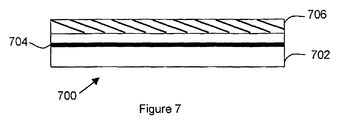
- FIG. 7 shows another alternative embodiment of a composite structure 700 from which a MEM component may be readily obtained.
- Silicon on insulator (SOI) substrate 702 has a buried layer of silicon dioxide layer 704 that acts as an etch stop.
- the buried silicon dioxide layer can be formed by several commercially available techniques, including implanting oxygen (O 2 ), deep into substrate 702.
- the silicon-oxide-silicon (which may be either doped to impart semiconductor properties or undoped) is adhesively bonded to substrate 706 to form a composite structure.
- substrate 706 is a glass substrate.
- FIG. 5 a topological view of an integrated circuit comprising a MEM component is shown.
- This circuit is an exemplary view of one type of MEM component that may be created using the process of the present invention.
- Beams 152 of about one micrometer wide and several millimeters in length are constructed using the above-described process. The thickness of these beams may range from about 20-30 micrometers up to about 100 micrometer.
- Support beams 154 may add rigidity to selected ones of beams 152.
- a very high aspect ratio may be achieved for the MEM component.
- very narrow, deep MEM sensors are obtained using the above described process steps.
- this type of sensor will have high capacitance value that is easy to detect.
- sensor interface may be achieved by electrically bonding to pads 156.
- the process of the present invention is independent of the substrate material. Since epoxy or organic adhesives, in general, readily bond a wide variety of substrates, substrates may be selected depending on the specific application in which the MEM component will interface. The low temperature bonding readily enables the use of gallium arsenide, silicon or other material on a glass substrate. Further, the process is readily applied to applications where silicon or gallium arsenide substrates are desired instead of a glass substrate.
- transistors or other circuit elements may be fabricated directly on the silicon, prior to creating the composite structure of Figure 2.
- structures can be formed on both sides of the beam.
- aluminum can be deposited between the silicon dioxide and the silicon layers (see Figure 1) to create a very conductive structure.
- the present invention relates to a fabrication process relating to a fabrication process for manufacture of micro-electromechanical (MEM) devices such as cantilever supported beams.
- MEM micro-electromechanical
- This fabrication process requires only two lithographic masking steps and offers moveable electromechanical devices with high electrical isolation.
- a preferred embodiment of the process uses electrically insulating glass substrate as the carrier substrate and single crystal silicon as the MEM component material.
- the process further includes deposition of an optional layer of insulating material such as silicon dioxide on top of a layer of doped silicon grown on a silicon substrate.
- the silicon dioxide is epoxy bonded to the glass substrate to create a silicon-silicon dioxide-epoxy-glass structure.
- the silicon is patterned using anisotropic plasma dry etching techniques. A second patterning then follows to pattern the silicon dioxide layer and an oxygen plasma etch is performed to undercut the epoxy film and to release the silicon MEM component.
- This two-mask process provides single crystal silicon MEMs with electrically isolated MEM component. Retaining silicon dioxide insulating material in selected areas mechanically supports the MEM component.
Landscapes
- Engineering & Computer Science (AREA)
- Manufacturing & Machinery (AREA)
- Microelectronics & Electronic Packaging (AREA)
- Micromachines (AREA)
Abstract
Description
- The present invention relates to micro electromechanical (MEM) systems and, more particularly, to fabrication of MEM components with a high electrically isolated substrate.
- Micro electromechanical (MEM) components are being progressively introduced into many electronic circuit applications and a variety of micro-sensor applications. Examples of MEM components are radio frequency (RF) switches, high Q capacitors, pressure transducers and accelerometers. One such MEM component, a MEM switch, is disclosed in U.S. Patent No. 5,578,976 which issued to Rockwell International Corporation the assignee of the present application. This MEM switch is fabricated on a GaAs substrate with a cantilevered switch arm formed from silicon dioxide-deposited upon a sacrificial layer. Contacts and electrodes are readily formed through deposition of gold and aluminum, respectively.
- Another prior art method for creating cantilever beams required a deep anisotrophic etch into a silicon substrate and application of either a silicon nitride or oxide layer to coat the top and side walls of the exposed cut. An isotrophic etch of the silicon substrate undercuts and frees the MEM component. Unfortunately, this method is not readily adaptable for applications where non-conductive, high resistance substrates such as glass are desired for high isolation applications.
- Another method, often referred to as a surface micro machining, uses a sacrificial layer such as silicon dioxide deposited on a silicon substrate. MEM component material, poly-silicon, by way of example, is then deposited, patterned and released. The poly-silicon layer is etched by a reactive ion etch to expose the sacrificial silicon dioxide layer. The sacrificial layer is then etched, usually with an acid (hydrofluoric acid), to release the MEM component. However, MEM components created from poly-silicon have limited mechanical strength and exhibit relatively poor electrical isolation. Further, production yields are poor using this method since the wet hydrofluoric etch often results in the MEM component sticking to the substrate rather than being suspended.
- If a high electrical isolation is required, fabrication of MEM components on a glass substrate generally required either ionic (application of high voltage) or fusion (high temperature) bonding techniques to create MEM components. Both of these bonding techniques are poorly suited for use when semiconductor devices are present on the same substrate. Specifically, with ionic bonding the high voltage may damage sensitive electrical components while the high processing temperature associated with both ionic and fusion bonding may cause junctions depths to change affecting device performance and reliability. It is also known that such bonding techniques require very smooth surface to surface contact to ensure a good bond. If the surfaces do not mate within acceptable tolerances, the reaction or inter-diffusion process will result in a defective bond. Further, these bonding techniques are sensitive to surface contamination or irregularities which may result in bond failure sites or a decrease in production yields.
- In another prior art method, a glass substrate is bonded to a silicon dioxide layer using ionic or fusion bonding techniques. Prior to bonding, the silicon dioxide layer is deposited on top of a silicon wafer so that the bonding process forms a glass-silicon dioxide-silicon composite structure. The silicon is patterned and wet etched to define the MEM component.
- As mentioned above, ionic or fusion bonding require a high process temperature which are in the range of about 450°C to 500°C. Further, the glass substrate must be conductive to facilitate bonding with the silicon dioxide. Such conductivity precludes achieving high electrical isolation in the final MEM system. Further still, with the wet etch used to release the MEM component, the structure often sticks to the substrate rather than remaining free standing.
- The present invention provides a method that uses adhesive bonding to form a MEM component on top of a glass substrate so that the MEM component is electrically isolated from the substrates. Further, the present process uses a dry etch to release the MEM component. Thus, whatever the merits of the above described prior art methods, they do not achieve the benefits of the present invention.
- The present invention relates to a fabrication process for manufacture of micro electromechanical (MEM) systems having components, such as cantilever supported beams, spaced above the substrate. This fabrication process uses as few as two lithographic masking steps depending on the complexity of the device and provides MEM components that are electrically isolated from the substrate.
- Specifically, in one embodiment of the present invention, a composite silicon-film-glass substrate structure is formed. The silicon layer is processed by either polishing, grinding or etching to obtain the desired thickness, patterned to define the MEM component and etched to expose the film layer. The film layer is a sacrificial layer that is then patterned and dry etched to release the MEM component.
- In other embodiment of the present invention, the process comprises the steps of growing a layer of doped silicon on a silicon wafer or substrate and depositing a layer of insulating material such as silicon dioxide on the doped silicon. This embodiment includes the use of a silicon on insulator (SOI) substrate. The silicon substrate is adhesive bonded to a glass substrate to create a composite silicon-silicon dioxide-silicon-adhesive-glass structure. The silicon is patterned and etched using anisotropic plasma dry etching techniques. A second patterning then follows to pattern the silicon dioxide layer and an oxygen plasma etch is performed to undercut the adhesive film and to release the doped silicon MEM component. This two-mask process provides single crystal silicon MEM component that is electrically isolated from the glass substrate but mechanically joined thereto.
- The adhesive serves a dual role as a bonding agent and as a sacrificial layer that can be readily removed to release the MEM component in an effective and efficient manner. Specifically, the dry oxygen plasma etch undercuts the adhesive without causing the MEM component to stick to adjacent surfaces ― a common problem with wet chemical releases. In addition the oxygen plasma is a benign process with respect to the other material of the composite structure.
- In accordance with the present invention, fabrication of very small cantilever supported beams, switches or other micro electromechanical structures are readily incorporated with other circuit functions on an integrated circuit device. The present invention is particularly well suited for manufacture of long narrow freestanding beams parallel to the substrate that can move in response to pressure, electromagnetic, mechanical or other such stimuli.
- Also, the surfaces of the substrates need not be perfectly smooth since the adhesive layer eliminates the need to use fusion or ionic bonding techniques to form the composite structure. Indeed, pre-existing diffusions or surface irregularities may be present in the substrates with little or no impact on yield or the integrity of the composite structure. This provides very flexible design options since electrical components may be positioned in close proximity to the MEM component.
- These and other advantages of the present invention not specifically described above will become clear within the detailed discussion herein.
-
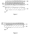
- Figure 1 is a sectioned view of the first and second substrates which, when combined, will form a composite structure in accordance with the present invention.
- Figure 2 is a sectioned view of the substrates, shown in Figure 1 adhesively bonded to form one embodiment of a composite structure.
- Figure 3 is a sectioned view of the composite structure of Figure 2 illustrating a partial etching to define a micro electro-mechanical (MEM) component in accordance with the present invention.
- Figure 4 is a sectioned view of the composite structure of Figure 2 illustrating the release of the MEM component in accordance with the present invention.
- Figure 5 illustrates, in a general manner, a MEM component manufactured on a glass substrate in accordance with the present invention.
- Figure 6 is a sectioned view of another embodiment of a composite structure formed in accordance with the present invention.
- Figure 7 shows another alternative embodiment of a
composite structure 700 from which a MEM component may be readily obtained. - In the following description of the preferred embodiment, reference is made to the accompanying drawings, which form a part hereof, and in which is shown by way of illustration a specific embodiment in which the invention may be practiced. In the following description, numerous specific details are set forth in order to provide a through understanding of the present invention. It will be apparent, however, to one skilled in the art that the present invention may be practiced without these specific details. In other instances, well-known structures and techniques are not shown or discussed in detail in order not to unnecessarily obscure the present invention. Reference will now be made in detail to the preferred embodiments of the invention, examples of which are illustrated in the accompanying drawings.
- Referring now to Figure 1,
process 100 comprises a plurality of steps performed on two principal wafer-like elements: aglass substrate 102 shown with anorganic adhesive layer 104 applied to one surface and asacrificial semiconductor substrate 106. The two substrates are each individually processed, combined to form a composite structure and then further processed to define a micro electro-mechanical (MEM) component. - MEM components are miniaturized freestanding structures spaced above but physically connected to
substrate 102 and electrically coupled to other circuit elements onsubstrate 102. Examples of typical MEM components may include cantilever supported switches, diaphragms for pressure sensing applications or suspended beams supported at each end but otherwise physically spaced from the substrate. -
Substrate 102 preferably comprises an electrically insulating glass material such quartz, sodium silicate Na2O-SiO2 or borosilicate B2O3- SiO2. One preferred substrate uses a high silica glass substrate marketed under the tradename of Vycor, available from Corning Incorporated of Corning, New York. Alternatively, in applications where it is desired to utilizesubstrate 102 as a conducting element, a semiconductor material may be used. Anorganic adhesive layer 104 is spun ontosubstrate 102. Spin coating would provide the most practical method for application of the organic adhesive. However, other coating methods such as spray coating, or staged partially-cured thin films, which are applied to the wafer, by way of example, may be used to deposit organic adhesive layer with substantially uniform thickness. -
Carrier substrate 106 is either a p-type or n-type silicon wafer such as is commonly used in semiconductor processing; the orientation and conductivity of the wafer will, of course, depend on the specific application. Using known semiconductor processing techniques, asilicon layer 108 is grown oncarrier substrate 106.Layer 108 may be doped with boron, germanium or other known dopants to impart an etch stop and semiconductor properties. Using semiconductor device manufacturing techniques, electrical components such as resistors, capacitors, inductors or interconnects may be readily formed. An optionalsilicon dioxide layer 110 is grown on top ofsilicon layer 108 and anorganic adhesive layer 112 is spun on top. The silicon dioxide layer may be eliminated if the rigidity of the MEM component is not critical. Further, eitheradhesive layer - The term organic adhesive refers to thermal setting plastics in which a chemical reaction occurs. The chemical reaction increases cross-linking of the polymer to increase rigidity as well as creating a chemical bond with the surfaces being mated.
- While epoxy is the most versatile type of organic adhesive for the present invention1 other potential adhesives include polyimide, silicones, acrylics, polyurethanes, polybenzimidazoles and polyquinoralines. Other types of organic adhesives such as thermal plastics, which require heating above their melting point like wax, would not be of value for this application. The selection of the adhesive would depend in large part on the polymer's thermal characteristics and particularly its glass transition temperature. Other selection criteria include economics, adhesive strength on different substrates, cure shrinkage, environmental compatibility and coefficient of thermal expansion.
- The glass transition temperature is the temperature at which chemical bonds can freely rotate around the central polymer chain. As a result, below the glass transition temperature, the polymer, when cured, is a rigid glass-like material. Above the glass transition, however, the polymer is a softer elstomeric material. Further at the glass transition temperature, there is a substantial increase in the coefficient of thermal expansion (CTE). Accordingly, when the glass transition temperature is exceeded, there is an increase in the CTE and there is a relief of stress in the polymer layer.
-
Substrates substrates -
Substrates adhesive layers -
Composite structure 200 is shown more clearly in Figure 2. The organicadhesive layers composite structure 200 for a sequence of oven bakes at elevated temperatures of up to 180 °C to reduce cure shrinkage. The recommended cure temperatures depend on the type of epoxy used. Preferably) once cured, the epoxy is able to withstand elevated temperatures typically associated with many semiconductor - processing steps (that is, a temperature up to 250°C) without additional shrinkage or substantial degradation. - Further) the adhesive should have a limited amount of cure shrinkage so as to minimize the possibility of inducing cracking or stress fractures in
composite structure 200. The phrase "cure shrinkage" refers to a change in volume of a thermosetting adhesive during the cure cycle due to the reaction, generally an out-gassing product or rearrangement of the polymer itself. Cure shrinkage can cause considerable pressure to develop along the length of the bond during processing. - An additional component closely associated with cure shrinkage is the adhesive's CTE at the cure temperature and at the operating temperature. Generally, organic adhesives will have a higher CTE than any other material present in the MEM component. This means that the adhesive will expand at a higher rate than will other material as the ambient temperature increases. Although an inorganic filler material may be added to the adhesive to reduce the CTE such fillers are not recommended in this application since such inorganic filler material cannot be etched using oxygen plasma during the structural releasing step.
-
Substrate 102 may also be selected for a desired CTE. The substrate in one preferred embodiment has a CTE that is substantially similar to but less than that of silicon so that the resulting MEM component will be slightly stretched (or in tension). In this manner, smaller structures will retain some degree of elasticity and will be less susceptible to developing a bow or collapsing upon release of the MEM component. It will be appreciated that if the CTE ofsubstrate 102 is greater than that of silicon, the MEM component will be in compression upon release. Larger beams may be capable of retaining the structural integrity in compression after all process steps are complete. Use ofglass substrate 102 was selected in the described embodiment primarily to achieve high electrical isolation. However, one skilled in the art will appreciate that the process steps of the present invention may be applied to selected substrates other than the above described glass substrate due the versatility of the bonding and sacrificial layer. - Due to the number of material types present in the
composite structure 200, thermal processing and the mismatching of thermal coefficients may impart shear fractures or stress cracks in one or both substrates or in the various layers. The CTE in the bond line of the MEM component will depend upon the polymer used, its curing agent, and the thermal cycle used to cure the polymer. When the processing and operating temperatures are maintained so that the polymer is not exposed to temperatures exceeding the glass transition temperature, the polymer is a rigid glass-like material and the CTE is minimized. If the glass transition temperature is exceeded, however, there will be an increase in the CTE, which may result in a relief of stress in the polymer layer. Any such stress relief aftercomposite structure 200 is formed may deformcomposite structure 200. Since flexible or elastomeric polymers will have a high CTE, a thin bond line is desirable to minimize structural damage in the event the glass transition temperature is inadvertently exceeded. In one preferred embodiment, the bond line has a thickness of about five (5) to seven (7) microns. - Referring again to Figure 1, the next step is to remove
substrate 106 and exposesilicon layer 108.Substrate 106 is removed using a backside chemical etch. A mechanical grinding or polishing step may proceed the chemical etch to reduce the amount of silicon etching required or to reduce the selectivity needed in the etch stop. Sincesubstrate 106 primarily functions as a sacrificial carrier forsilicon layer 108, there is no need to preservesubstrate 106 in the region of the MEM component so as to facilitate subsequent processing ofsilicon layer 108. Alternatively, if a specific application required thick or rigid beams, one skilled in the art will appreciate thatsubstrate 106 could be patterned and selectively etched for use as beam material or retained in adjacent areas as a substrate for integrated circuit devices. - As shown in Figure 3, an optional layer of
aluminum 116 is deposited onto the exposed surface ofsilicon layer 108.Aluminum 116 is patterned with a first mask to form conducting areas and to expose selected portions ofsilicon layer 108. The aluminum is either lifted off or etched using an aluminum-specific chemical agent. Although not shown, an oxide or nitride cap may be applied on top of thealuminum layer 116 to form a protective barrier. - With
silicon layer 108 exposed through thealuminum 116, an anisotropic etch defines the structural dimensions of the MEM component. This etch stops upon reaching thesilicon dioxide layer 110. - A second mask is applied to pattern the insulating
silicon dioxide layer 110 and then etched. It is important to note that due to its insulating properties, portions ofsilicon dioxide layer 110 may be retained to mechanically support selective areas of the MEM component while maintaining electrical isolation. Specifically as shown in Figure 5, holes 150 may be etched intosilicon dioxide layer 110 to facilitate etchingadhesive layer 120. - Referring now to Figure 4,
adhesive layer 120 is etched in a final process step to release the MEM component. In the preferred embodiment, dry oxygen (O2) plasma etch undercutsadhesive layer 120. Since this plasma etch is a dry release, manufacturing yields are improved relative to wet etching. Specifically, as one familiar with semiconductor technology will appreciate, wet etching may lower production yields as water molecules get trapped under the released MEM components causing the MEM component to stick tosubstrate 102. - Upon MEM component release, stress forces along the bond line will be substantially released. Further, any pressure generated by shrinkage of the organic adhesive during cure will be significantly reduced after processing by dicing the wafers into discrete devices resulting in mechanically stable devices.
- Another embodiment of a composite structure formed in accordance with the present invention is shown in Figure 6.
Structure 600 comprises a first andsecond substrate substrate 102 is preferably a glass substrate that exhibits high electrical isolation whilesubstrate 106 is a semiconductor substrate.Substrate 106 may be either p or n-type and may be selectively doped to impart conductive or semiconductor properties.Substrates adhesive film 602. - If preferred,
substrate 106 may be ground and polished to a desired thickness, patterned to define a MEM component and etched to expose theadhesive film 602. The film is then patterned and dry etched to release the MEM component. As will be understood,substrates - Figure 7 shows another alternative embodiment of a
composite structure 700 from which a MEM component may be readily obtained. Silicon on insulator (SOI)substrate 702 has a buried layer ofsilicon dioxide layer 704 that acts as an etch stop. The buried silicon dioxide layer can be formed by several commercially available techniques, including implanting oxygen (O2), deep intosubstrate 702. The silicon-oxide-silicon (which may be either doped to impart semiconductor properties or undoped) is adhesively bonded tosubstrate 706 to form a composite structure. In the preferred embodiment,substrate 706 is a glass substrate. Using the techniques described above, the MEM component is defined and released by the two-mask patterning and etching process. - Referring again to Figure 5, a topological view of an integrated circuit comprising a MEM component is shown. This circuit is an exemplary view of one type of MEM component that may be created using the process of the present invention.
Beams 152 of about one micrometer wide and several millimeters in length are constructed using the above-described process. The thickness of these beams may range from about 20-30 micrometers up to about 100 micrometer. One skilled in the art will appreciate that the above-described dimensions may be readily changed depending on the specific application. Support beams 154 may add rigidity to selected ones ofbeams 152. - With the present invention a very high aspect ratio may be achieved for the MEM component. By way of example, very narrow, deep MEM sensors are obtained using the above described process steps. Thus this type of sensor will have high capacitance value that is easy to detect. Advantageously, sensor interface may be achieved by electrically bonding to
pads 156. - The process of the present invention is independent of the substrate material. Since epoxy or organic adhesives, in general, readily bond a wide variety of substrates, substrates may be selected depending on the specific application in which the MEM component will interface. The low temperature bonding readily enables the use of gallium arsenide, silicon or other material on a glass substrate. Further, the process is readily applied to applications where silicon or gallium arsenide substrates are desired instead of a glass substrate.
- It will be appreciated that it is also very desirable in many applications to position electronic circuits in close proximity to the MEM component. With the present invention, transistors or other circuit elements may be fabricated directly on the silicon, prior to creating the composite structure of Figure 2. Further, with the present invention, structures can be formed on both sides of the beam. By way of example, aluminum can be deposited between the silicon dioxide and the silicon layers (see Figure 1) to create a very conductive structure. One skilled in the art will appreciate that the low process temperatures employed to create the composite structure, to define or to release the MEM components has minimal impact on junction depths or circuit device parameters.
- While certain exemplary preferred embodiments have been described and shown in the accompanying drawings, it is to be understood that such embodiments are merely illustrative of and not restrictive on the broad invention. Further, it is to be understood that this invention shall not be limited to the specific construction and arrangements shown and described since various modifications or changes may occur to those of ordinary skill in the art without departing from the spirit and scope of the invention as claimed.
- The present invention relates to a fabrication process relating to a fabrication process for manufacture of micro-electromechanical (MEM) devices such as cantilever supported beams. This fabrication process requires only two lithographic masking steps and offers moveable electromechanical devices with high electrical isolation. A preferred embodiment of the process uses electrically insulating glass substrate as the carrier substrate and single crystal silicon as the MEM component material.
- The process further includes deposition of an optional layer of insulating material such as silicon dioxide on top of a layer of doped silicon grown on a silicon substrate. The silicon dioxide is epoxy bonded to the glass substrate to create a silicon-silicon dioxide-epoxy-glass structure. The silicon is patterned using anisotropic plasma dry etching techniques. A second patterning then follows to pattern the silicon dioxide layer and an oxygen plasma etch is performed to undercut the epoxy film and to release the silicon MEM component. This two-mask process provides single crystal silicon MEMs with electrically isolated MEM component. Retaining silicon dioxide insulating material in selected areas mechanically supports the MEM component.
Claims (26)
- A method for fabricating a micro electromechanical (MEM) component on a substrate comprising the steps of:Providing a first substrate (106, 108);Providing a second substrate (102);Adhesively bonding (at 120) said first substrate (106, 108) to said second substrate (102) to form a composite structure (200);Patterning and etching said first substrate (106, 108) to define a MEM component; andPatterning and etching said adhesive bond (120) to release said MEM component.
- The method of claim 1 further comprising the step of reducing the thickness of said first substrate (106, 108) prior to the first of said patterning and etching steps.
- A method for fabricating a micro electromechanical (MEM) component on a substrate comprising the steps of:Providing a first substrate (106);Providing a first layer of material (108) on said first substrate (106);Providing a second substrate (102);Adhesively bonding (at 120) said first layer of material (108) to said second substrate (102) to form a composite structure (200);Patterning and etching said first substrate (106) to expose said first layer of material (108);Patterning and etching said first layer of material (108) to define a MEM component; andEtching said adhesive bond (120) to release said MEM component.
- The method of any preceding claim further comprising the step of doping said first substrate (106, 108) or said first layer of material (108), respectively, to impart etch stop and/or semiconductor properties thereto.
- The method of claim 3 or 4 wherein said etching of said adhesive bond (120) comprises the step of performing an oxygen plasma etch to selectively undercut and to release the MEM component while maintaining said composite structure.
- The method of any of claims 3 to 5 further comprising the steps of growing a silicon dioxide layer (110) on top of said first layer of material (108) and depositing a layer of organic adhesive (112) on top of said silicon dioxide layer (110).
- The method of any of claims 3 to 5 wherein said bonding step further comprises the step of:Depositing a layer of organic adhesive (104, 112) on at least one of said second substrate (102) and said first layer of material (108) with a layer of epoxy;Positioning said first and second substrate (106 and 102) in a vacuum chamber with said adhesive layer (104, 112) there-between;Evacuating the air in said chamber;Joining together said first and second substrate so as to form a single epoxy bond (120) there-between; andCuring said epoxy.
- A method for fabricating a micro electromechanical component on a substrate comprising the steps of:Providing a silicon substrate (106);Depositing a layer of semiconductor material (108) on said silicon substrate (106);Providing a highly insulating substrate (102);Bonding said highly insulating substrate to said semiconductor material to form a composite structure (200);Patterning and etching said silicon substrate (106) to expose said semiconductor material (108);Patterning and etching said semiconductor material (108) to define a micro electromechanical component; andPerforming an isotropic etch to selectively undercut the bond (120) and to release said micro electromechanical component.
- The method of claim 3 or 8 wherein said etching of said first substrate (106) or said silicon substrate (106), respectively, comprises the step of performing an anisotropic plasma dry etch.
- The method of claims 8 or 9 further comprising the steps of growing a silicon dioxide layer (110) on top of said semiconductor material (108);preferably further comprising a step of depositing a layer of organic adhesive (112, 104) on top of at least one of said silicon dioxide layer (110) and said insulating substrate (102) prior to said bonding step; and
wherein said etching of said adhesive bond step preferably comprises the step of performing an isotropic etch to selectively undercut said bond (120) and to release the micro electromechanical component while maintaining said composite structure (200). - The method of claim 8 or 9 wherein said bonding step further comprises the step of:Depositing a layer of organic adhesive (104, 112) on one side of said at least one of said semiconductor material (108) and said highly insulating substrate (102);Positioning said first and second substrate (106 and 102) in a vacuum chamber with said adhesive layer (104, 112) there-between;Evacuating the air in said chamber;Placing said first and second substrates into physical contact so as to form a single adhesive bond (120) there-between; andCuring said adhesive.
- The method as claimed in any of claims 8 to 11 further comprising the step of providing aplurality of electronic elements in close proximity to said micro electromechanical component on said highly insulating substrate (102);
wherein said providing step preferably comprises the step of fabricating transistors or other circuit elements directly in semiconductor material prior to said bonding step; and
wherein said providing step preferably comprises the step of fabricating circuit elements on said semiconductor material (108) after said etching step to remove said first substrate (106) so as to provide circuit elements on the side of said micro electromechanical component facing away from said highly insulating substrate (102) where said circuit elements comprise resistors, capacitors, inductors and interconnects. - A method for fabricating a micro electromechanical component on a substrate comprising the steps of:Providing a silicon-on-insulator (SOI) substrate (702) having a buried layer of insulating material (704);Providing a highly insulating substrate (706);Bonding said highly insulating substrate (706) to said SOI substrate (702) to form a composite structure (700);Patterning and etching said SOI substrate (702) to expose said buried layer insulating material (704);Patterning and etching said buried layer insulating material (704) to define a micro electromechanical component; andSelectively etching to undercut the bond under said micro electromechanical component so as to release the micro electromechanical component.
- The method of claim 3, 8 or 13 wherein said second substrate (102) or said highly insulating substrate (102, 706), respectively, comprises a glass substrate, preferably a highly insulating glass substrate.
- The method of claim 3, 4 or 14 wherein said etching of said first substrate (106) or said SOI substrate (702), respectively, comprises the step of performing an anisotropic plasma dry etch.
- The method of claim 15 further comprising the step of depositing a layer of organic adhesive on said SOI substrate (702) prior to said bonding step.
- The method of claim 3, 8 or 13
wherein said bond is an adhesive bond made by an organic adhesive selected from the following: epoxy, polyimide, silicone, acrylic, polyurethane, polybenzimidazole and polyquinoraline; andpreferably further comprising the step of depositing a conductive layer of metal (116) on top of said composite structure (200; 700) after said patterning and etching of said silicon substrate step or said SOI substrate step. - The method of claim 17 wherein said etch process step to release the MEM component from said bond (120) comprises an oxygen plasma etch.
- The method of claims 8 to 10 or claim 17 wherein said bonding step further comprises the step of:Positioning said substrate with at least one said adhesive layer (112, 104) there-between;Evacuating the air between said substrates;Placing said substrates into physical contact to form a single adhesive bond, for example epoxy bond (120), thereby forming a composite structure (200; 700); andCuring said adhesive.
- The method of any of claims 3 to 6, 8 to 11, 13 to 19, wherein said organic adhesive bond or said adhesive bond, respectively, is epoxy.
- In a semiconductor device, a composite structure comprising:a first substrate (106) having a first layer of material (108) on said first substrate;a second substrate (102) adhesively bonded (at 120) to said first layer of material (108) to form a composite structure (200), anda micro electromechanical (MEM) component formed in said first layer of material (108) and having said first substrate (106) removed therefrom, said MEM component being separated from said second substrate (102) by a dimension substantially equal to the dimension of said adhesive bond (120).
- The composite structure of claim 21 wherein said first substrate (106) is substantially completely removed from said first layer of material (108) and said composite structure further comprises:a layer of conductive material (116) deposited on top of said first layer (108); anda protective barrier layer (110).
- The composite structure of claim 21 wherein:said first layer of material (108) comprises material exhibiting semiconductor properties;said composite structure (200) preferably further comprises a protective barrier layer (110) between said first layer of material (108) and said adhesive bond layer (120); and
wherein said second substrate (102) preferably comprises a substrate having high electrical isolation properties. - In a semiconductor device, a composite structure comprising:a first substrate (106, 108);a second substrate (102) adhesively bonded (at 120) to said first substrate (106, 108) to form a composite structure (200), anda micro electromechanical (MEM) component formed in said first substrate (106, 108), said MEM component being separated from said second substrate (102) by a dimension substantially equal to the dimension of said adhesive bond (120).
- The composite structure of claim 24 wherein the thickness of said first substrate defines said MEM component, said first substrate further comprises:a layer of conductive material (116); anda protective barrier layer (110);said first substrate (106, 108) preferably comprising material exhibiting semiconductor properties and said second substrate (102) preferably comprising material exhibiting high electrical isolation.
- The composite structure of claim 24 wherein said composite structure (200) further comprises a protective barrier layer (110) between said first layer of material (108) and said adhesive bond layer (120).
Applications Claiming Priority (2)
| Application Number | Priority Date | Filing Date | Title |
|---|---|---|---|
| US09/075,008 US6159385A (en) | 1998-05-08 | 1998-05-08 | Process for manufacture of micro electromechanical devices having high electrical isolation |
| US75008 | 1998-05-08 |
Publications (3)
| Publication Number | Publication Date |
|---|---|
| EP0955668A2 true EP0955668A2 (en) | 1999-11-10 |
| EP0955668A3 EP0955668A3 (en) | 2003-05-07 |
| EP0955668B1 EP0955668B1 (en) | 2005-10-05 |
Family
ID=22122964
Family Applications (1)
| Application Number | Title | Priority Date | Filing Date |
|---|---|---|---|
| EP99109110A Expired - Lifetime EP0955668B1 (en) | 1998-05-08 | 1999-05-07 | Process for manufacture of micro electromechanical devices having high electrical isolation |
Country Status (4)
| Country | Link |
|---|---|
| US (2) | US6159385A (en) |
| EP (1) | EP0955668B1 (en) |
| JP (1) | JP2000210900A (en) |
| DE (1) | DE69927547T2 (en) |
Cited By (10)
| Publication number | Priority date | Publication date | Assignee | Title |
|---|---|---|---|---|
| EP1193523A2 (en) * | 2000-09-28 | 2002-04-03 | Xerox Corporation | Micro-electro-mechanical mirror structure |
| WO2002098788A2 (en) * | 2001-06-04 | 2002-12-12 | Honeywell International Inc. | Applications of a strain-compensated heavily doped etch stop for silicon structure formation |
| US6949202B1 (en) | 1999-10-26 | 2005-09-27 | Reflectivity, Inc | Apparatus and method for flow of process gas in an ultra-clean environment |
| US6965468B2 (en) | 2003-07-03 | 2005-11-15 | Reflectivity, Inc | Micromirror array having reduced gap between adjacent micromirrors of the micromirror array |
| US7041224B2 (en) | 1999-10-26 | 2006-05-09 | Reflectivity, Inc. | Method for vapor phase etching of silicon |
| US7153443B2 (en) | 2003-03-28 | 2006-12-26 | Texas Instruments Incorporated | Microelectromechanical structure and a method for making the same |
| US7189332B2 (en) | 2001-09-17 | 2007-03-13 | Texas Instruments Incorporated | Apparatus and method for detecting an endpoint in a vapor phase etch |
| US7645704B2 (en) | 2003-09-17 | 2010-01-12 | Texas Instruments Incorporated | Methods and apparatus of etch process control in fabrications of microstructures |
| CN101468784B (en) * | 2007-12-25 | 2011-07-27 | 微智半导体股份有限公司 | Semiconductor miniature suspension structure and method of producing the same |
| CN113206360A (en) * | 2015-08-10 | 2021-08-03 | 株式会社村田制作所 | High frequency module |
Families Citing this family (79)
| Publication number | Priority date | Publication date | Assignee | Title |
|---|---|---|---|---|
| SE512041C3 (en) * | 1998-05-06 | 2000-02-07 | Thomas Laurell | Procedure for etching openings |
| US6159385A (en) | 1998-05-08 | 2000-12-12 | Rockwell Technologies, Llc | Process for manufacture of micro electromechanical devices having high electrical isolation |
| GB9819821D0 (en) * | 1998-09-12 | 1998-11-04 | Secr Defence | Improvements relating to micro-machining |
| US6399516B1 (en) * | 1998-10-30 | 2002-06-04 | Massachusetts Institute Of Technology | Plasma etch techniques for fabricating silicon structures from a substrate |
| DE69940577D1 (en) * | 1998-11-09 | 2009-04-23 | Seiko Instr Inc | Near field sensing head and manufacturing method therefor |
| US6060336A (en) * | 1998-12-11 | 2000-05-09 | C.F. Wan Incorporated | Micro-electro mechanical device made from mono-crystalline silicon and method of manufacture therefore |
| US6211598B1 (en) * | 1999-09-13 | 2001-04-03 | Jds Uniphase Inc. | In-plane MEMS thermal actuator and associated fabrication methods |
| US6803755B2 (en) | 1999-09-21 | 2004-10-12 | Rockwell Automation Technologies, Inc. | Microelectromechanical system (MEMS) with improved beam suspension |
| US6798312B1 (en) * | 1999-09-21 | 2004-09-28 | Rockwell Automation Technologies, Inc. | Microelectromechanical system (MEMS) analog electrical isolator |
| US6617750B2 (en) | 1999-09-21 | 2003-09-09 | Rockwell Automation Technologies, Inc. | Microelectricalmechanical system (MEMS) electrical isolator with reduced sensitivity to inertial noise |
| US6346030B1 (en) * | 2000-05-09 | 2002-02-12 | Sandia Corporation | Microdevice having interior cavity with high aspect ratio surface features and associated methods of manufacture and use |
| US6383833B1 (en) * | 2000-05-23 | 2002-05-07 | Silverbrook Research Pty Ltd. | Method of fabricating devices incorporating microelectromechanical systems using at least one UV curable tape |
| DE60032521T2 (en) * | 2000-05-24 | 2007-11-22 | Silverbrook Research Pty. Ltd., Balmain | METHOD FOR PRODUCING MICROELECTROMECHANICAL DEVICES CONTAINING COMPONENTS BY USING AT LEAST ONE UV-HARDENABLE BAND |
| US6501282B1 (en) | 2000-09-29 | 2002-12-31 | Rockwell Automation Technologies, Inc. | Highly sensitive capacitance comparison circuit |
| US6583374B2 (en) | 2001-02-20 | 2003-06-24 | Rockwell Automation Technologies, Inc. | Microelectromechanical system (MEMS) digital electrical isolator |
| KR100405176B1 (en) * | 2001-04-12 | 2003-11-12 | 조동일 | An Electrical Isolation Method for Single-Crystalline Silicon MEMS Using Localized SOI Structure |
| US6768628B2 (en) | 2001-04-26 | 2004-07-27 | Rockwell Automation Technologies, Inc. | Method for fabricating an isolated microelectromechanical system (MEMS) device incorporating a wafer level cap |
| US6756310B2 (en) * | 2001-09-26 | 2004-06-29 | Rockwell Automation Technologies, Inc. | Method for constructing an isolate microelectromechanical system (MEMS) device using surface fabrication techniques |
| US6794271B2 (en) | 2001-09-28 | 2004-09-21 | Rockwell Automation Technologies, Inc. | Method for fabricating a microelectromechanical system (MEMS) device using a pre-patterned bridge |
| US6569701B2 (en) | 2001-10-25 | 2003-05-27 | Rockwell Automation Technologies, Inc. | Method for fabricating an isolated microelectromechanical system device |
| US6761829B2 (en) | 2001-04-26 | 2004-07-13 | Rockwell Automation Technologies, Inc. | Method for fabricating an isolated microelectromechanical system (MEMS) device using an internal void |
| US6815243B2 (en) * | 2001-04-26 | 2004-11-09 | Rockwell Automation Technologies, Inc. | Method of fabricating a microelectromechanical system (MEMS) device using a pre-patterned substrate |
| US7005314B2 (en) * | 2001-06-27 | 2006-02-28 | Intel Corporation | Sacrificial layer technique to make gaps in MEMS applications |
| US6664786B2 (en) | 2001-07-30 | 2003-12-16 | Rockwell Automation Technologies, Inc. | Magnetic field sensor using microelectromechanical system |
| KR100408761B1 (en) * | 2001-08-23 | 2003-12-11 | 조동일 | Fabrication Method for (100) directional GaAs beam with rectangular cross-section |
| US6649987B1 (en) * | 2001-10-09 | 2003-11-18 | Glimmerglass Networks, Inc. | MEMS hybrid structure having flipped silicon with external standoffs |
| US6593870B2 (en) | 2001-10-18 | 2003-07-15 | Rockwell Automation Technologies, Inc. | MEMS-based electrically isolated analog-to-digital converter |
| US6690178B2 (en) | 2001-10-26 | 2004-02-10 | Rockwell Automation Technologies, Inc. | On-board microelectromechanical system (MEMS) sensing device for power semiconductors |
| WO2003045837A2 (en) * | 2001-11-26 | 2003-06-05 | Wisconsin Alumni Research Foundation | Stress control of semiconductor microstructures for thin film growth |
| KR100416266B1 (en) * | 2001-12-18 | 2004-01-24 | 삼성전자주식회사 | MEMS structure having a blocked-sacrificial layer support/anchor and a fabrication method of the same |
| US6709948B2 (en) * | 2001-12-21 | 2004-03-23 | Texas Instruments Incorporated | Process for manufacturing a two-axis mirror |
| US7813634B2 (en) | 2005-02-28 | 2010-10-12 | Tessera MEMS Technologies, Inc. | Autofocus camera |
| KR20030067847A (en) * | 2002-02-08 | 2003-08-19 | 조동일 | Fabrication Method for GaAs Semicoductor Microstructure |
| US7346981B2 (en) * | 2002-08-07 | 2008-03-25 | Teledyne Licensing, Llc | Method for fabricating microelectromechanical system (MEMS) devices |
| US20040027029A1 (en) * | 2002-08-07 | 2004-02-12 | Innovative Techology Licensing, Llc | Lorentz force microelectromechanical system (MEMS) and a method for operating such a MEMS |
| US6770506B2 (en) * | 2002-12-23 | 2004-08-03 | Motorola, Inc. | Release etch method for micromachined sensors |
| US6975193B2 (en) * | 2003-03-25 | 2005-12-13 | Rockwell Automation Technologies, Inc. | Microelectromechanical isolating circuit |
| US6979872B2 (en) * | 2003-05-13 | 2005-12-27 | Rockwell Scientific Licensing, Llc | Modules integrating MEMS devices with pre-processed electronic circuitry, and methods for fabricating such modules |
| US7054052B2 (en) * | 2003-09-04 | 2006-05-30 | Frank Niklaus | Adhesive sacrificial bonding of spatial light modulators |
| DE10342155A1 (en) * | 2003-09-12 | 2005-04-07 | Robert Bosch Gmbh | Process for the production of etch holes and / or etch trenches as well as membrane sensor unit |
| US7078337B2 (en) * | 2003-09-30 | 2006-07-18 | Agere Systems Inc. | Selective isotropic etch for titanium-based materials |
| US7585744B2 (en) * | 2003-12-08 | 2009-09-08 | Freescale Semiconductor, Inc. | Method of forming a seal for a semiconductor device |
| WO2005089348A2 (en) * | 2004-03-15 | 2005-09-29 | Georgia Tech Research Corporation | Packaging for micro electro-mechanical systems and methods of fabricating thereof |
| US7470557B2 (en) * | 2004-04-19 | 2008-12-30 | Hewlett-Packard Development Company, L.P. | Self-aligned coating on released MEMS |
| WO2005104257A1 (en) * | 2004-04-23 | 2005-11-03 | Agency For Science, Technology And Research | Micro-electromechanical device |
| KR100548388B1 (en) * | 2004-07-20 | 2006-02-02 | 삼성전자주식회사 | Inductor element having high quality factor and a fabrication mentod thereof |
| US7287415B2 (en) * | 2004-09-30 | 2007-10-30 | Teledyne Licensing, Llc | Microelectromechanical system (MEMS) viscosity sensor for fluid health monitoring |
| US7838322B1 (en) * | 2005-02-28 | 2010-11-23 | Tessera MEMS Technologies, Inc. | Method of enhancing an etch system |
| US7718457B2 (en) * | 2005-04-05 | 2010-05-18 | Analog Devices, Inc. | Method for producing a MEMS device |
| US7337671B2 (en) | 2005-06-03 | 2008-03-04 | Georgia Tech Research Corp. | Capacitive microaccelerometers and fabrication methods |
| KR100748741B1 (en) | 2005-07-28 | 2007-08-13 | 현대자동차주식회사 | Method for manufacture of silicon release structure using Silicon On Insulator |
| KR100727185B1 (en) | 2005-07-28 | 2007-06-13 | 현대자동차주식회사 | Method for manufacture of silicon release structure using Silicon On Insulator |
| US7303935B2 (en) * | 2005-09-08 | 2007-12-04 | Teledyne Licensing, Llc | High temperature microelectromechanical (MEM) devices and fabrication method |
| KR100658202B1 (en) | 2005-09-12 | 2006-12-15 | (주)마이크로인피니티 | Floating body for micro structure and a method of manufacturing thereof |
| US7329932B2 (en) * | 2005-09-12 | 2008-02-12 | Teledyne Licensing, Llc | Microelectromechanical (MEM) viscosity sensor and method |
| US7328604B2 (en) * | 2005-09-22 | 2008-02-12 | Teledyne Licensing, Llc | Microelectromechanical (MEM) fluid health sensing device and fabrication method |
| FR2892714B1 (en) * | 2005-10-27 | 2007-12-21 | Commissariat Energie Atomique | METHOD FOR ETCHING A SACRIFICIAL LAYER FOR A MICRO-FACTORY STRUCTURE |
| TW200717519A (en) * | 2005-10-28 | 2007-05-01 | Univ Nat Chiao Tung | Asynchronous first-in-first-out cell |
| FI119729B (en) | 2005-11-23 | 2009-02-27 | Vti Technologies Oy | A method of making a microelectromechanical component and a microelectromechanical component |
| US7578189B1 (en) | 2006-05-10 | 2009-08-25 | Qualtre, Inc. | Three-axis accelerometers |
| US7767484B2 (en) | 2006-05-31 | 2010-08-03 | Georgia Tech Research Corporation | Method for sealing and backside releasing of microelectromechanical systems |
| ATE524413T1 (en) * | 2007-07-03 | 2011-09-15 | Em Microelectronic Marin Sa | METHOD FOR PRODUCING MICROMECHANICAL PARTS FROM CRYSTALLINE MATERIAL |
| TWI340121B (en) * | 2007-12-14 | 2011-04-11 | Memsmart Semiconductor Corp | A micro suspended structure and its manufacturing method |
| CN101364044B (en) * | 2008-09-26 | 2011-07-27 | 北京大学 | Minuteness processing method for upper substrate of glass |
| WO2015157202A1 (en) | 2014-04-09 | 2015-10-15 | Corning Incorporated | Device modified substrate article and methods for making |
| US10543662B2 (en) | 2012-02-08 | 2020-01-28 | Corning Incorporated | Device modified substrate article and methods for making |
| TWI617437B (en) | 2012-12-13 | 2018-03-11 | 康寧公司 | Facilitated processing for controlling bonding between sheet and carrier |
| US10014177B2 (en) | 2012-12-13 | 2018-07-03 | Corning Incorporated | Methods for processing electronic devices |
| US10086584B2 (en) | 2012-12-13 | 2018-10-02 | Corning Incorporated | Glass articles and methods for controlled bonding of glass sheets with carriers |
| US9340443B2 (en) | 2012-12-13 | 2016-05-17 | Corning Incorporated | Bulk annealing of glass sheets |
| WO2015050688A1 (en) * | 2013-10-02 | 2015-04-09 | Cavendish Kinetics, Inc | Method for achieving good adhesion between dielectric and organic material |
| US10510576B2 (en) | 2013-10-14 | 2019-12-17 | Corning Incorporated | Carrier-bonding methods and articles for semiconductor and interposer processing |
| JP6770432B2 (en) | 2014-01-27 | 2020-10-14 | コーニング インコーポレイテッド | Articles and methods for controlled binding of thin sheets to carriers |
| WO2016187186A1 (en) | 2015-05-19 | 2016-11-24 | Corning Incorporated | Articles and methods for bonding sheets with carriers |
| CN107810168A (en) | 2015-06-26 | 2018-03-16 | 康宁股份有限公司 | Method and product comprising sheet material and carrier |
| US10190702B2 (en) * | 2016-03-15 | 2019-01-29 | Dunan Microstaq, Inc. | MEMS based solenoid valve |
| TW201825623A (en) | 2016-08-30 | 2018-07-16 | 美商康寧公司 | Siloxane plasma polymers for sheet bonding |
| TWI821867B (en) | 2016-08-31 | 2023-11-11 | 美商康寧公司 | Articles of controllably bonded sheets and methods for making same |
| CN111615567B (en) | 2017-12-15 | 2023-04-14 | 康宁股份有限公司 | Method for treating substrate and method for producing article including adhesive sheet |
Citations (3)
| Publication number | Priority date | Publication date | Assignee | Title |
|---|---|---|---|---|
| EP0665590A2 (en) * | 1994-01-31 | 1995-08-02 | Canon Kabushiki Kaisha | Microstructure, process for manufacturing thereof and devices incorporating the same |
| EP0711029A2 (en) * | 1994-11-07 | 1996-05-08 | Canon Kabushiki Kaisha | Microstructure and method of forming the same |
| EP0763844A1 (en) * | 1995-09-14 | 1997-03-19 | Canon Kabushiki Kaisha | Method of manufacturing micro-tip and female mold substrate therefor, and method of manufacturing probe with micro-tip |
Family Cites Families (21)
| Publication number | Priority date | Publication date | Assignee | Title |
|---|---|---|---|---|
| JP2821830B2 (en) * | 1992-05-14 | 1998-11-05 | セイコーインスツルメンツ株式会社 | Semiconductor thin film device and its application device and method of manufacturing semiconductor thin film device |
| US5804314A (en) | 1994-03-22 | 1998-09-08 | Hewlett-Packard Company | Silicon microstructures and process for their fabrication |
| US5528452A (en) * | 1994-11-22 | 1996-06-18 | Case Western Reserve University | Capacitive absolute pressure sensor |
| US5578976A (en) * | 1995-06-22 | 1996-11-26 | Rockwell International Corporation | Micro electromechanical RF switch |
| US5783340A (en) | 1995-09-06 | 1998-07-21 | Sandia Corporation | Method for photolithographic definition of recessed features on a semiconductor wafer utilizing auto-focusing alignment |
| US5994816A (en) | 1996-12-16 | 1999-11-30 | Mcnc | Thermal arched beam microelectromechanical devices and associated fabrication methods |
| US5761350A (en) | 1997-01-22 | 1998-06-02 | Koh; Seungug | Method and apparatus for providing a seamless electrical/optical multi-layer micro-opto-electro-mechanical system assembly |
| US5959516A (en) | 1998-01-08 | 1999-09-28 | Rockwell Science Center, Llc | Tunable-trimmable micro electro mechanical system (MEMS) capacitor |
| US6232847B1 (en) | 1997-04-28 | 2001-05-15 | Rockwell Science Center, Llc | Trimmable singleband and tunable multiband integrated oscillator using micro-electromechanical system (MEMS) technology |
| US5903380A (en) | 1997-05-01 | 1999-05-11 | Rockwell International Corp. | Micro-electromechanical (MEM) optical resonator and method |
| US6071426A (en) | 1997-12-08 | 2000-06-06 | The Regents Of The University Of California | Micro benchtop optics by bulk silicon micromachining |
| US6046066A (en) | 1998-03-10 | 2000-04-04 | National Science Council Of Rep. Of China | Method of forming cantilever structure in microelectromanical system |
| US6159385A (en) | 1998-05-08 | 2000-12-12 | Rockwell Technologies, Llc | Process for manufacture of micro electromechanical devices having high electrical isolation |
| US5995688A (en) | 1998-06-01 | 1999-11-30 | Lucent Technologies, Inc. | Micro-opto-electromechanical devices and method therefor |
| US6100477A (en) | 1998-07-17 | 2000-08-08 | Texas Instruments Incorporated | Recessed etch RF micro-electro-mechanical switch |
| US6060336A (en) * | 1998-12-11 | 2000-05-09 | C.F. Wan Incorporated | Micro-electro mechanical device made from mono-crystalline silicon and method of manufacture therefore |
| US6137206A (en) | 1999-03-23 | 2000-10-24 | Cronos Integrated Microsystems, Inc. | Microelectromechanical rotary structures |
| US6094102A (en) | 1999-04-30 | 2000-07-25 | Rockwell Science Center, Llc | Frequency synthesizer using micro electro mechanical systems (MEMS) technology and method |
| US6232841B1 (en) | 1999-07-01 | 2001-05-15 | Rockwell Science Center, Llc | Integrated tunable high efficiency power amplifier |
| US6188322B1 (en) | 1999-09-28 | 2001-02-13 | Rockwell Technologies, Llc | Method for sensing electrical current |
| US6348788B1 (en) | 1999-09-28 | 2002-02-19 | Rockwell Automation Technologies, Inc. | High resolution current sensing apparatus |
-
1998
- 1998-05-08 US US09/075,008 patent/US6159385A/en not_active Expired - Lifetime
-
1999
- 1999-05-07 EP EP99109110A patent/EP0955668B1/en not_active Expired - Lifetime
- 1999-05-07 DE DE69927547T patent/DE69927547T2/en not_active Expired - Lifetime
- 1999-05-10 JP JP11128807A patent/JP2000210900A/en active Pending
-
2000
- 2000-11-09 US US09/710,326 patent/US6617657B1/en not_active Expired - Lifetime
Patent Citations (3)
| Publication number | Priority date | Publication date | Assignee | Title |
|---|---|---|---|---|
| EP0665590A2 (en) * | 1994-01-31 | 1995-08-02 | Canon Kabushiki Kaisha | Microstructure, process for manufacturing thereof and devices incorporating the same |
| EP0711029A2 (en) * | 1994-11-07 | 1996-05-08 | Canon Kabushiki Kaisha | Microstructure and method of forming the same |
| EP0763844A1 (en) * | 1995-09-14 | 1997-03-19 | Canon Kabushiki Kaisha | Method of manufacturing micro-tip and female mold substrate therefor, and method of manufacturing probe with micro-tip |
Non-Patent Citations (1)
| Title |
|---|
| STORMENT C W ET AL: "FLEXIBLE, DRY-RELEASED PROCESS FOR ALUMINIUM ELECTROSTATIC ACTUATORS" JOURNAL OF MICROELECTROMECHANICAL SYSTEMS, IEEE INC. NEW YORK, US, vol. 3, no. 3, 1 September 1994 (1994-09-01), pages 90-96, XP000469763 ISSN: 1057-7157 * |
Cited By (15)
| Publication number | Priority date | Publication date | Assignee | Title |
|---|---|---|---|---|
| US7041224B2 (en) | 1999-10-26 | 2006-05-09 | Reflectivity, Inc. | Method for vapor phase etching of silicon |
| US6949202B1 (en) | 1999-10-26 | 2005-09-27 | Reflectivity, Inc | Apparatus and method for flow of process gas in an ultra-clean environment |
| EP1193523A3 (en) * | 2000-09-28 | 2003-05-07 | Xerox Corporation | Micro-electro-mechanical mirror structure |
| EP1193523A2 (en) * | 2000-09-28 | 2002-04-03 | Xerox Corporation | Micro-electro-mechanical mirror structure |
| WO2002098788A2 (en) * | 2001-06-04 | 2002-12-12 | Honeywell International Inc. | Applications of a strain-compensated heavily doped etch stop for silicon structure formation |
| WO2002098788A3 (en) * | 2001-06-04 | 2003-10-09 | Honeywell Int Inc | Applications of a strain-compensated heavily doped etch stop for silicon structure formation |
| US7189332B2 (en) | 2001-09-17 | 2007-03-13 | Texas Instruments Incorporated | Apparatus and method for detecting an endpoint in a vapor phase etch |
| US7153443B2 (en) | 2003-03-28 | 2006-12-26 | Texas Instruments Incorporated | Microelectromechanical structure and a method for making the same |
| US6985277B2 (en) | 2003-07-03 | 2006-01-10 | Reflectivity, Inc | Micromirror array having reduced gap between adjacent micromirrors of the micromirror array |
| US6970281B2 (en) | 2003-07-03 | 2005-11-29 | Reflectivity, Inc. | Micromirror array having reduced gap between adjacent micromirrors of the micromirror array |
| US6965468B2 (en) | 2003-07-03 | 2005-11-15 | Reflectivity, Inc | Micromirror array having reduced gap between adjacent micromirrors of the micromirror array |
| US7645704B2 (en) | 2003-09-17 | 2010-01-12 | Texas Instruments Incorporated | Methods and apparatus of etch process control in fabrications of microstructures |
| CN101468784B (en) * | 2007-12-25 | 2011-07-27 | 微智半导体股份有限公司 | Semiconductor miniature suspension structure and method of producing the same |
| CN113206360A (en) * | 2015-08-10 | 2021-08-03 | 株式会社村田制作所 | High frequency module |
| CN113206360B (en) * | 2015-08-10 | 2022-08-30 | 株式会社村田制作所 | High frequency module |
Also Published As
| Publication number | Publication date |
|---|---|
| US6159385A (en) | 2000-12-12 |
| JP2000210900A (en) | 2000-08-02 |
| DE69927547D1 (en) | 2006-02-16 |
| EP0955668B1 (en) | 2005-10-05 |
| US6617657B1 (en) | 2003-09-09 |
| DE69927547T2 (en) | 2006-05-18 |
| EP0955668A3 (en) | 2003-05-07 |
Similar Documents
| Publication | Publication Date | Title |
|---|---|---|
| US6159385A (en) | Process for manufacture of micro electromechanical devices having high electrical isolation | |
| US20040227201A1 (en) | Modules integrating MEMS devices with pre-processed electronic circuitry, and methods for fabricating such modules | |
| US5455202A (en) | Method of making a microelectric device using an alternate substrate | |
| US10038055B2 (en) | Substrate structure with embedded layer for post-processing silicon handle elimination | |
| EP1198835B1 (en) | Dual wafer attachment process | |
| US6060336A (en) | Micro-electro mechanical device made from mono-crystalline silicon and method of manufacture therefore | |
| JP3073442B2 (en) | Sealed cavity device and method | |
| Tilmans et al. | Wafer-level packaged RF-MEMS switches fabricated in a CMOS fab | |
| US7268081B2 (en) | Wafer-level transfer of membranes with gas-phase etching and wet etching methods | |
| US6610582B1 (en) | Field-assisted fusion bonding | |
| Niklaus et al. | Low-temperature wafer-level transfer bonding | |
| ATE511493T1 (en) | METHOD FOR PRODUCING PRECISE MICROELECTROMECHANICAL STRUCTURES, AND MICROSTRUCTURES SO PRODUCED | |
| JP2002185014A (en) | Method for manufacturing sensor using diaphragm and equipment constituted using the sensor | |
| KR20070086316A (en) | Method for transferring a circuit to a grounding plane | |
| Han et al. | Micromechanical velcro | |
| EP1741669B1 (en) | Hidden hinge MEMS device | |
| US6777312B2 (en) | Wafer-level transfer of membranes in semiconductor processing | |
| TWI289879B (en) | Method of fabricating pressure sensor | |
| US20060286388A1 (en) | Anodic bonding process for ceramics | |
| US7060521B2 (en) | Bonding method | |
| RU2704199C1 (en) | Method of creating structure - silicon on insulator | |
| CN107161944A (en) | Structure for the device with integrated micro-mechano electric system | |
| Tuck et al. | Patterned Polymer Bonding with 3-D capability for Microelectromechanical Systems (MEMS) Inertial Sensors | |
| JP2004090102A (en) | Method for depositing semi-conductor film on insulating substrate | |
| JP2002264095A (en) | Method of manufacturing on-insulator silicon and polysilicon wafer |
Legal Events
| Date | Code | Title | Description |
|---|---|---|---|
| PUAI | Public reference made under article 153(3) epc to a published international application that has entered the european phase |
Free format text: ORIGINAL CODE: 0009012 |
|
| AK | Designated contracting states |
Kind code of ref document: A2 Designated state(s): AT BE CH CY DE DK ES FI FR GB GR IE IT LI LU MC NL PT SE |
|
| AX | Request for extension of the european patent |
Free format text: AL;LT;LV;MK;RO;SI |
|
| PUAL | Search report despatched |
Free format text: ORIGINAL CODE: 0009013 |
|
| AK | Designated contracting states |
Designated state(s): AT BE CH CY DE DK ES FI FR GB GR IE IT LI LU MC NL PT SE |
|
| AX | Request for extension of the european patent |
Extension state: AL LT LV MK RO SI |
|
| RIC1 | Information provided on ipc code assigned before grant |
Ipc: 7B 81C 1/00 B Ipc: 7B 81B 3/00 B Ipc: 7H 01L 21/00 A |
|
| 17P | Request for examination filed |
Effective date: 20030625 |
|
| AKX | Designation fees paid |
Designated state(s): DE FR GB IT |
|
| 17Q | First examination report despatched |
Effective date: 20040127 |
|
| GRAP | Despatch of communication of intention to grant a patent |
Free format text: ORIGINAL CODE: EPIDOSNIGR1 |
|
| GRAS | Grant fee paid |
Free format text: ORIGINAL CODE: EPIDOSNIGR3 |
|
| GRAA | (expected) grant |
Free format text: ORIGINAL CODE: 0009210 |
|
| AK | Designated contracting states |
Kind code of ref document: B1 Designated state(s): DE FR GB IT |
|
| REG | Reference to a national code |
Ref country code: GB Ref legal event code: FG4D |
|
| REF | Corresponds to: |
Ref document number: 69927547 Country of ref document: DE Date of ref document: 20060216 Kind code of ref document: P |
|
| ET | Fr: translation filed | ||
| PLBE | No opposition filed within time limit |
Free format text: ORIGINAL CODE: 0009261 |
|
| STAA | Information on the status of an ep patent application or granted ep patent |
Free format text: STATUS: NO OPPOSITION FILED WITHIN TIME LIMIT |
|
| 26N | No opposition filed |
Effective date: 20060706 |
|
| PGFP | Annual fee paid to national office [announced via postgrant information from national office to epo] |
Ref country code: GB Payment date: 20140527 Year of fee payment: 16 |
|
| PGFP | Annual fee paid to national office [announced via postgrant information from national office to epo] |
Ref country code: IT Payment date: 20140527 Year of fee payment: 16 Ref country code: DE Payment date: 20140529 Year of fee payment: 16 Ref country code: FR Payment date: 20140519 Year of fee payment: 16 |
|
| REG | Reference to a national code |
Ref country code: DE Ref legal event code: R119 Ref document number: 69927547 Country of ref document: DE |
|
| GBPC | Gb: european patent ceased through non-payment of renewal fee |
Effective date: 20150507 |
|
| PG25 | Lapsed in a contracting state [announced via postgrant information from national office to epo] |
Ref country code: IT Free format text: LAPSE BECAUSE OF NON-PAYMENT OF DUE FEES Effective date: 20150507 |
|
| REG | Reference to a national code |
Ref country code: FR Ref legal event code: ST Effective date: 20160129 |
|
| PG25 | Lapsed in a contracting state [announced via postgrant information from national office to epo] |
Ref country code: GB Free format text: LAPSE BECAUSE OF NON-PAYMENT OF DUE FEES Effective date: 20150507 Ref country code: DE Free format text: LAPSE BECAUSE OF NON-PAYMENT OF DUE FEES Effective date: 20151201 |
|
| PG25 | Lapsed in a contracting state [announced via postgrant information from national office to epo] |
Ref country code: FR Free format text: LAPSE BECAUSE OF NON-PAYMENT OF DUE FEES Effective date: 20150601 |