EP0955917B1 - Flexible tissue ablation elements for making long lesions - Google Patents
Flexible tissue ablation elements for making long lesions Download PDFInfo
- Publication number
- EP0955917B1 EP0955917B1 EP96939661A EP96939661A EP0955917B1 EP 0955917 B1 EP0955917 B1 EP 0955917B1 EP 96939661 A EP96939661 A EP 96939661A EP 96939661 A EP96939661 A EP 96939661A EP 0955917 B1 EP0955917 B1 EP 0955917B1
- Authority
- EP
- European Patent Office
- Prior art keywords
- wire
- edge
- electrode
- adjacent windings
- support body
- Prior art date
- Legal status (The legal status is an assumption and is not a legal conclusion. Google has not performed a legal analysis and makes no representation as to the accuracy of the status listed.)
- Expired - Lifetime
Links
Images


Classifications
-
- A—HUMAN NECESSITIES
- A61—MEDICAL OR VETERINARY SCIENCE; HYGIENE
- A61B—DIAGNOSIS; SURGERY; IDENTIFICATION
- A61B18/00—Surgical instruments, devices or methods for transferring non-mechanical forms of energy to or from the body
- A61B18/04—Surgical instruments, devices or methods for transferring non-mechanical forms of energy to or from the body by heating
- A61B18/12—Surgical instruments, devices or methods for transferring non-mechanical forms of energy to or from the body by heating by passing a current through the tissue to be heated, e.g. high-frequency current
- A61B18/14—Probes or electrodes therefor
- A61B18/1492—Probes or electrodes therefor having a flexible, catheter-like structure, e.g. for heart ablation
-
- A—HUMAN NECESSITIES
- A61—MEDICAL OR VETERINARY SCIENCE; HYGIENE
- A61B—DIAGNOSIS; SURGERY; IDENTIFICATION
- A61B5/00—Measuring for diagnostic purposes; Identification of persons
- A61B5/24—Detecting, measuring or recording bioelectric or biomagnetic signals of the body or parts thereof
- A61B5/25—Bioelectric electrodes therefor
- A61B5/279—Bioelectric electrodes therefor specially adapted for particular uses
- A61B5/28—Bioelectric electrodes therefor specially adapted for particular uses for electrocardiography [ECG]
- A61B5/283—Invasive
- A61B5/287—Holders for multiple electrodes, e.g. electrode catheters for electrophysiological study [EPS]
-
- A—HUMAN NECESSITIES
- A61—MEDICAL OR VETERINARY SCIENCE; HYGIENE
- A61B—DIAGNOSIS; SURGERY; IDENTIFICATION
- A61B5/00—Measuring for diagnostic purposes; Identification of persons
- A61B5/68—Arrangements of detecting, measuring or recording means, e.g. sensors, in relation to patient
- A61B5/6846—Arrangements of detecting, measuring or recording means, e.g. sensors, in relation to patient specially adapted to be brought in contact with an internal body part, i.e. invasive
- A61B5/6847—Arrangements of detecting, measuring or recording means, e.g. sensors, in relation to patient specially adapted to be brought in contact with an internal body part, i.e. invasive mounted on an invasive device
- A61B5/6852—Catheters
- A61B5/6858—Catheters with a distal basket, e.g. expandable basket
-
- A—HUMAN NECESSITIES
- A61—MEDICAL OR VETERINARY SCIENCE; HYGIENE
- A61N—ELECTROTHERAPY; MAGNETOTHERAPY; RADIATION THERAPY; ULTRASOUND THERAPY
- A61N1/00—Electrotherapy; Circuits therefor
- A61N1/02—Details
- A61N1/04—Electrodes
- A61N1/05—Electrodes for implantation or insertion into the body, e.g. heart electrode
- A61N1/056—Transvascular endocardial electrode systems
-
- A—HUMAN NECESSITIES
- A61—MEDICAL OR VETERINARY SCIENCE; HYGIENE
- A61N—ELECTROTHERAPY; MAGNETOTHERAPY; RADIATION THERAPY; ULTRASOUND THERAPY
- A61N1/00—Electrotherapy; Circuits therefor
- A61N1/02—Details
- A61N1/04—Electrodes
- A61N1/06—Electrodes for high-frequency therapy
-
- A—HUMAN NECESSITIES
- A61—MEDICAL OR VETERINARY SCIENCE; HYGIENE
- A61N—ELECTROTHERAPY; MAGNETOTHERAPY; RADIATION THERAPY; ULTRASOUND THERAPY
- A61N1/00—Electrotherapy; Circuits therefor
- A61N1/40—Applying electric fields by inductive or capacitive coupling ; Applying radio-frequency signals
-
- G—PHYSICS
- G01—MEASURING; TESTING
- G01K—MEASURING TEMPERATURE; MEASURING QUANTITY OF HEAT; THERMALLY-SENSITIVE ELEMENTS NOT OTHERWISE PROVIDED FOR
- G01K1/00—Details of thermometers not specially adapted for particular types of thermometer
- G01K1/02—Means for indicating or recording specially adapted for thermometers
- G01K1/026—Means for indicating or recording specially adapted for thermometers arrangements for monitoring a plurality of temperatures, e.g. by multiplexing
-
- G—PHYSICS
- G01—MEASURING; TESTING
- G01K—MEASURING TEMPERATURE; MEASURING QUANTITY OF HEAT; THERMALLY-SENSITIVE ELEMENTS NOT OTHERWISE PROVIDED FOR
- G01K3/00—Thermometers giving results other than momentary value of temperature
- G01K3/08—Thermometers giving results other than momentary value of temperature giving differences of values; giving differentiated values
- G01K3/14—Thermometers giving results other than momentary value of temperature giving differences of values; giving differentiated values in respect of space
-
- A—HUMAN NECESSITIES
- A61—MEDICAL OR VETERINARY SCIENCE; HYGIENE
- A61B—DIAGNOSIS; SURGERY; IDENTIFICATION
- A61B17/00—Surgical instruments, devices or methods, e.g. tourniquets
- A61B2017/00017—Electrical control of surgical instruments
- A61B2017/00022—Sensing or detecting at the treatment site
- A61B2017/00084—Temperature
- A61B2017/00088—Temperature using thermistors
-
- A—HUMAN NECESSITIES
- A61—MEDICAL OR VETERINARY SCIENCE; HYGIENE
- A61B—DIAGNOSIS; SURGERY; IDENTIFICATION
- A61B17/00—Surgical instruments, devices or methods, e.g. tourniquets
- A61B2017/00017—Electrical control of surgical instruments
- A61B2017/00022—Sensing or detecting at the treatment site
- A61B2017/00084—Temperature
- A61B2017/00092—Temperature using thermocouples
-
- A—HUMAN NECESSITIES
- A61—MEDICAL OR VETERINARY SCIENCE; HYGIENE
- A61B—DIAGNOSIS; SURGERY; IDENTIFICATION
- A61B17/00—Surgical instruments, devices or methods, e.g. tourniquets
- A61B2017/00831—Material properties
- A61B2017/0088—Material properties ceramic
-
- A—HUMAN NECESSITIES
- A61—MEDICAL OR VETERINARY SCIENCE; HYGIENE
- A61B—DIAGNOSIS; SURGERY; IDENTIFICATION
- A61B18/00—Surgical instruments, devices or methods for transferring non-mechanical forms of energy to or from the body
- A61B2018/00053—Mechanical features of the instrument of device
- A61B2018/00059—Material properties
- A61B2018/00071—Electrical conductivity
- A61B2018/00083—Electrical conductivity low, i.e. electrically insulating
-
- A—HUMAN NECESSITIES
- A61—MEDICAL OR VETERINARY SCIENCE; HYGIENE
- A61B—DIAGNOSIS; SURGERY; IDENTIFICATION
- A61B18/00—Surgical instruments, devices or methods for transferring non-mechanical forms of energy to or from the body
- A61B2018/00053—Mechanical features of the instrument of device
- A61B2018/00107—Coatings on the energy applicator
- A61B2018/00148—Coatings on the energy applicator with metal
-
- A—HUMAN NECESSITIES
- A61—MEDICAL OR VETERINARY SCIENCE; HYGIENE
- A61B—DIAGNOSIS; SURGERY; IDENTIFICATION
- A61B18/00—Surgical instruments, devices or methods for transferring non-mechanical forms of energy to or from the body
- A61B2018/00053—Mechanical features of the instrument of device
- A61B2018/0016—Energy applicators arranged in a two- or three dimensional array
-
- A—HUMAN NECESSITIES
- A61—MEDICAL OR VETERINARY SCIENCE; HYGIENE
- A61B—DIAGNOSIS; SURGERY; IDENTIFICATION
- A61B18/00—Surgical instruments, devices or methods for transferring non-mechanical forms of energy to or from the body
- A61B2018/00636—Sensing and controlling the application of energy
- A61B2018/00773—Sensed parameters
- A61B2018/00791—Temperature
-
- A—HUMAN NECESSITIES
- A61—MEDICAL OR VETERINARY SCIENCE; HYGIENE
- A61B—DIAGNOSIS; SURGERY; IDENTIFICATION
- A61B18/00—Surgical instruments, devices or methods for transferring non-mechanical forms of energy to or from the body
- A61B18/04—Surgical instruments, devices or methods for transferring non-mechanical forms of energy to or from the body by heating
- A61B18/12—Surgical instruments, devices or methods for transferring non-mechanical forms of energy to or from the body by heating by passing a current through the tissue to be heated, e.g. high-frequency current
- A61B18/14—Probes or electrodes therefor
- A61B2018/1405—Electrodes having a specific shape
- A61B2018/1435—Spiral
Definitions
- the invention relates to a device for ablating body tissue according to the preamble of claim 1.
- a device is disclosed in document WO-A-95/10318.
- the invention generally relates to systems for ablating myocardial tissue for the treatment of cardiac conditions.
- Physicians make use of catheters and other devices today in medical procedures to gain access into interior regions of the body to ablate targeted tissue areas. It is important for the physician to be able to precisely locate the device, and control its emission of energy within the body during tissue ablation procedures
- ablation is used to treat cardiac rhythm disturbances.
- a physician steers a catheter through a main vein or artery into the interior region of the heart that is to be treated.
- the physician places an ablating element carried on the catheter near the cardiac tissue that is to be ablated.
- the physician directs energy from the ablating element to ablate the tissue and form a lesion.
- Atrial fibrillation requires the formation of long lesions of different curvilinear shapes in heart tissue.
- Such long lesion patterns require the deployment within the heart of flexible ablating elements having multiple ablating regions.
- the formation of these lesions by ablation can provide the same therapeutic benefits the complex suture patterns that the surgical maze procedure presently provides, but without invasive, open heart surgery.
- ablating energy must be governed to avoid incidences of unwanted tissue damage and coagulum formation.
- the delivery of ablating energy must also be carefully controlled to assure the formation of uniform and continuous lesions, without hot spots and/or gaps forming in the ablated tissue.
- the WO 95/10318 discloses a device of the initially described type.
- the device for ablating body tissue includes a support body and a wire wound about the support body in adjacent windings to form an elongated electrode having at least one edge adjoining the support body.
- a connection is coupling the wire to a source of ablation energy for transmission by the elongated electrode to ablate tissue.
- the adjacent windings are spaced farther apart away from the at least one edge than at the at least one edge. This imparts enhanced flexibility to the elongated electrode and therefore allows a precise control of the ablating process.
- the adjacent windings are spaced apart by at least 1/5 of the width of the wire. In a preferred implementation, the windings are spaced apart by about 1/2 of the width of the wire.
- spacing between adjacent windings varies away from the edge. In another implementation, spacing between adjacent windings is generally uniform away from the edge.
- a temperature sensing element is carried by the electrode near the at least one edge, where the adjacent windings are closer together to support it.
- This specification discloses multiple electrode structures that embody aspects of the invention.
- This specification also discloses tissue ablation systems using multiple temperature sensing elements that embody other aspects of the invention.
- the illustrated and preferred embodiments discuss these structures, and systems in the context of catheter-based cardiac ablation. That is because these structures, and systems are well suited for use in the field of cardiac ablation.
- the invention is applicable for use in other tissue ablation applications.
- the various aspects of the invention have application in procedures for ablating tissue in the prostrate, brain, gall bladder, uterus, and other regions of the body, using systems that are not necessarily catheter-based.
- Figs. 1 and 2 show a flexible ablating element 10 that may be used to make lesions within the heart.
- the element 10 is carried at the distal end of a catheter body 12 of a probe 14.
- the probe 14 includes a handle 16 at the proximal end of the catheter body 12.
- the handle 16 and catheter body 12 carry a steering mechanism 18 for selectively bending or flexing the ablating element 10 in two opposite directions, as Figs. 1 and 2 show.
- the steering mechanism 18 can vary.
- the steering mechanism 18 includes a rotating cam wheel 20 with an external steering lever 22 (also see Fig. 1) carried by the handle 16.
- the cam wheel 20 holds the proximal ends of right and left steering wires 24.
- the wires 24 pass through the catheter body 12 and connect to the left and right sides of a resilient bendable wire or leaf spring 26 (see Fig. 4) supported at the distal end of the catheter body 12.
- Fig. 1 shows, forward movement of the steering lever 22 flexes or curves the ablating element 10 in one direction. Rearward movement of the steering lever 22 flexes or curves the ablating element 10 in the opposite.
- Various access techniques can be used to introduce the probe 14 into the desired region of the heart. For example, to enter the right atrium, the physician can direct the probe 14 through a conventional vascular introducer through the femoral vein. For entry into the left atrium, the physician can direct the probe 14 through a conventional vascular introducer retrograde through the aortic and mitral valves.
- the physician can use the delivery system shown in U.S. Pat. No. 5,636,634, entitled “Systems and Methods Using Guide Sheaths for Introducing, Deploying, and Stabilizing Cardiac Mapping and Ablation Probes.”
- the physician can verify intimate contact between the element 10 and heart tissue using conventional pacing and sensing techniques. Once the physician establishes intimate contact with tissue in the desired heart region, the physician applies ablating energy to the element 10.
- the type of ablating energy delivered to the element 10 can vary. In the illustrated and preferred embodiment, the element 10 transmits electromagnetic ablating energy with a frequency below about 1.0 GHz. This type of ablating energy, which is referred to as radio frequency energy, heats tissue, mostly ohmically, without electrically stimulating it. Alternatively, the element can transmit electromagnetic ablating energy with a frequency above 1.0 GHz. This type of ablating energy, which is referred to as microwave energy, produces both ohmic and dielectric tissue heating effects.
- the ablating element 10 can be conditioned to form elongated lesion patterns. These elongated lesion patterns can be continuous and extend along a straight line or along a curve. Elongated lesion patterns can be used to treat, for example, atrial fibrillation.
- Fig. 2 shows one embodiment of the flexible ablating element 10.
- a flexible body 42 carries on its exterior surface an array of spaced apart, generally flexible electrodes 44.
- each electrode 44 comprises wire wound in relatively tight spiral coils.
- the flexible body 42 is made of a polymeric, electrically nonconductive material, like polyethylene or polyurethane. It is the body 42 that carries within it the resilient bendable wire or leaf spring 26 with attached steering wires 24, as Fig. 4 shows, for flexing the body 42 and, with it, the array of electrodes 44.
- the coil electrodes 44 are made of electrically conducting wire material. Copper alloy, platinum, or stainless steel 304, 0303, 17-7 can be used. Drawn, filled tubing comprising a stainless steel outer tubing with a platinum or silver inner core can also be used.
- the electrically conducting wire material of the coil electrodes 44 can be coated with platinum-iridium or gold to improve its conduction properties and biocompatibility.
- the coil electrodes 44 can be made of closely wound, generally cylindrical wire, as the coil 44(a) shown in Figs. 5 and 6.
- the coil electrodes 44 are made of wound wire having a flat, or rectangular, cross section, as the coil 44(b) shown in Figs. 5 and 6. Wire having a flat cross section is preferred for several reasons.
- the tissue contact surface area of the resulting coil electrode 44(b) can be increased in an axial direction (i.e., along the body 42) without increasing the outside diameter of the electrode 44(b). More compact and easily deployable ablating elements 10 result.
- a wire having a flat cross section when wound into a coil electrode 44(b), permits a more efficient transmission of radio frequency ablation energy. Efficient transmission of radio frequency ablation energy by a coil electrode 44 requires keeping DC resistances between the point of electrical contact with the signal wire and any location on the coil at or below about 10 ohms. As resistances exceed about 10 ohms, the radio frequency current densities transmitted by the coil electrode 44 decrease substantially with the distance from the electrical connection.
- wire having a flat cross section it is possible to maintain the outside and inside diameters of the wound coil electrode 44(b), and still control resistances, solely by changing the width of the wire. Furthermore, as the width of the wire increases, so can the spacing between windings, decreasing the length of wire.
- the overall flexibility of the element 10 is important to consistently achieve intimate contact with heart tissue along the length of the element 10 and heart tissue. Without intimate contact along the entire length of the element 10, transmission of radio frequency energy lacks uniformity, thus resulting in undesired gaps in lesion patterns. Gaps in the lesion pattern are known to be proarrhythmic and can lead to atrial flutter.
- the ablation element 10 To consistently create intimate tissue contact, the ablation element 10 must have the capability to flexibly adapt to a wide range of contours and interior spaces within the heart.
- closely wound coil electrodes 44(a) and 44(b) shown in Fig. 5 and 6 do not always provide intimate tissue contact along the length of the element 10.
- Arrays of closely wound coil electrodes 44(a) and 44(b) often lack the flexibility to be easily bent into tight curves, having small curve radii.
- the individual coil electrodes 44(a) and 44(b) along the length of the element 10 often do not bend uniformly.
- Some coil electrodes 44(a) and 44(b) within the array retain straight, tangential profiles, particularly in the regions where the bend in the desired curve is most acute. Steering difficulties and gaps in lesion patterns may result.
- Figs. 7 and 8 show a preferred embodiment of the ablating element 10 incorporating this discovery.
- the same flexible body 42 carries on its exterior surface an array of spaced apart lengths of wound, helical coils forming electrodes, designated 44(c) and 44(d) in Figs. 7 and 8.
- the wire windings in each coil electrode 44(c) and 44(d) have been spread apart by a distance D. This results from increasing the pitch of the individual wire windings forming the coil electrodes 44(c) and 44(d).
- the spread-apart coil electrodes can be made of generally cylindrical wire, as the coil electrode 44(c) shown in Figs. 7 and 8. Still, however, it is preferred that the wire forming the spread-apart coil electrodes have a flat, or rectangular, cross section, as the coil electrode 44(d) shown in Figs. 7 and 8. The same reasons set forth above for preferring a flat cross section apply.
- the enhanced physical characteristics of the spread apart coil electrodes 44(c) and 44(d) in Figs. 7 and 8, when compared to the adjacent coil electrodes 44(a) and 44(b) in Figs. 5 and 6, can be demonstrated with respect to three physical functions. These functions differentiate flexibility among ablating elements 10 comprising arrays of spaced apart coil electrodes 44 in terms of flexed shape, degree of flexed curvature, and degree of tissue contact when flexed.
- the first function (F S ) (see Fig. 9) relates to the shape of a flexible coil ablating element 10, when flexed.
- the dimensions of the curvilinear ablating element 10 can be expressed in terms of a perpendicular distance to the first bend (D P ) and a maximum diameter (D M ).
- the second function (F T ) (see Fig. 10) relates to the degree of curvature defined by the ablating element 10, when flexed.
- F T can be expressed in terms of an average of the radii of curvature of the individual coil elements, as follows:
- F T points to how acutely the element 10 can be flexed. As F T decreases, the smaller the overall radius of curvature for the entire flexed element 10 is, and the more the element 10 is able to be flexed into a tight curve.
- the third function F c (see Fig. 11) relates to the uniformity of contact between tissue along the length of the flexed element 10.
- tangents can be drawn at the edges of adjacent coil electrodes C(i) and c(i+1), designated T(i) and T(i') in Fig. 11.
- the tangents T(i) and T(i') intersect for each electrode C(i) to form angles A T(i,i') .
- F C can be expressed as the average of the tangent angles along the length of the element, as follows:
- Individual coil electrodes 44 that are not sufficiently flexible to conform to the desired curve of the element 10 will form straight sections along the length of the flexed element 10, as Fig. 14 shows. Tissue contact between successive straight sections will not be uniform. Gaps in contact (designated G in Fig. 14) can occur, creating gaps in lesions and undesired proarrhythmic effects.
- Each ablation element E1-4 comprised six coil electrodes, each coil electrode being 12.5 mm in length. The coil electrodes were spaced apart by 2 mm. Each ablation element E1-4 used the same steering mechanism, as generally shown in Figs. 3 and 4 and as earlier described.
- the coil electrodes in ablation elements E1 and E2 used round wire having an outside diameter of 0.31 mm (0.012 inch).
- E1 the windings were adjacent, as represented by coil electrode 44(a) in Fig. 5.
- E2 the windings were spaced apart, as represented by electrode 44(C) in Fig. 7.
- Ablation elements E3 and E4 used flat wire, 0.51 mm (0.020 inch) wide and 0.13 mm (0.005 inch) high.
- the windings were adjacent, as represented by electrode 44(b) in Fig. 5.
- the windings were spaced apart, as represented by electrode 44(d) in Fig. 7.
- spaced apart windings create an overall more flexible ablation element, which can more readily be bent into shapes having smaller radii of curvature and with greater likelihood of creating continuous zones of intimate contact with tissue, like that shown in Fig. 15.
- adjacent windings can overlap during bending, which could potentially "pinch" the endocardium.
- the foregoing Example also shows that the spread apart flat wire configuration (E4) achieves the lowest F C (Table 3), and thus presents the highest likelihood of a conformal curve against tissue.
- the force to achieve a curve using the spread flat wire configuration E4 is greater than a spread round wire (E2) (Table 5), but the curve for the spread flat wire configuration (E4) is "tighter” and thus better than for the spread round wire configuration (E2) (Table 2).
- the distance D between the windings is at least 1/5 of the width W of the wound wire. It has been determined that spacing of less than 1/5 of the width W of the wound wire leads to significantly less flexibility, with greater potential for pinching tissue between the windings.
- the most preferred distance D is believed to be about 1/2 of the width W of the wound wire.
- the upper spacing limit becomes the distance at which the desired additive heating effect is observed to diminish.
- the diminishing of the additive heating effect can be determined empirically or mathematically under the desired operating conditions and geometries.
- U.S. Patent No. 5,810,802 shows the use of temperature sensing elements to measure temperatures along the length of the ablation element 10.
- the positioning of the temperature sensing elements on the electrode elements 10 is important for achieving reliable temperature sensing, particularly when the length of an individual coil on the element 10 exceeds about 10 mm, as contemplated in the preferred embodiment of this application.
- Fig. 12 shows a preferred embodiment of a coil electrode 50 designed for enhanced flexibility as well as to accommodate optimal placement of temperature sensing elements 52.
- the coil electrode 50 comprises two zones 54 and 56.
- the first zone 54 represents the majority of the electrode 50, occupying its entire mid portion.
- the first zone 54 comprises spaced apart windings to provide enhanced flexibility, as already described.
- the second zone 56 occupies each edge of the coil electrode 50.
- the second zone 56 comprises a region where the windings are closely adjacent to each other. The closeness of the windings provides a support structure for the temperature sensing element 52.
- the temperature sensing elements 52 are threaded up through the windings in each second zone 56 to lay upon its exterior surface. each second zone 56 to lay upon its exterior surface.
- the sensing elements 52 comprise thermocouples, and each is encapsulated in an epoxy or PTFE coating 58.
- thermistors can be used.
- the temperature sensing elements 52 can be secured to the inside surface of each second zone 56. Still alternatively, the sensing elements 52 can be sandwiched between the inside surface of the second zones 56 and the underlying flexible body 42.
- the two zone structure of the coil electrode 50 shown in Fig. 12 allows placement of temperature sensing elements 52 at the side edges 60 of the electrode 50. These edges 60 are where the electrode 50 abuts the underlying, non-electrically-conductive support body 42. RF current densities are high at these edges 60, because the edges 60 are regions where electrical conductivity is discontinuous. The resulting rise in current density at the electrode edges 60 generates localized regions of increased power density and, therefore, regions where higher temperatures exist. Given the elongated size of the electrode 50, temperature sensing elements 52 should preferably be located in these edge regions where high localized temperatures are to be expected. The closely spaced windings at the second region 56 accommodate such placement, without detracting from the overall flexibility that the first region 54 provides.
- a thin strip 66 of electrically insulating material (for example, an electrically nonconducting adhesive) is applied about the body 42 immediately next to the second regions 56. It has been observed that the presence of this electrically nonconducting strip 66 helps to minimize the presence of edge effect currents, which tend to be more pronounced in coil electrodes than other electrode structures.
- Fig. 13 shows an alternative embodiment of a coil electrode 60 designed for enhanced flexibility as well as to accommodate optimal placement of temperature sensing elements 52.
- Fig. 13 is similar to Fig. 12, in that the coil electrode 60 comprises at least two zones 62 and 64 of different spacing L between coil windings.
- the spacing D in the interior zone 54 is generally uniform, maintaining a distance at least 1/5 of the width of the wire.
- the spacing D in the interior zone 62 is at least 1/5 of the width of the wire, but the actual distance D varies along the interior zone 62.
- the spacing D in the interior zone 62 decreases progressively from the mid point of the coil 60 toward the edge zones 64, where the windings are closely spaced (i.e., less than 1/5 of the width of the wire) to support temperature sensing elements 52.
- the spacing D can vary along the interior zone 62 in a random fashion, while still observing the minimum spacing of 1/5 of the width of the wire. Practically speaking, it is to be expected that the spacing D will not be perfectly uniform or perfectly progressive, but will vary along the interior zone 62, because of normal tolerance deviations in the manufacturing process.
- the interior zone 62 (or, in Fig. 12, zone 54) could also carry a temperature sensing element 52.
- the use of a third, more centrally located temperature sensing element 52 is preferred when temperature prediction algorithms are used, as disclosed in U.S. Patent No. 5,810,802, as previously identified.
Description
- The invention relates to a device for ablating body tissue according to the preamble of
claim 1. Such a device is disclosed in document WO-A-95/10318. Accordingly, the invention generally relates to systems for ablating myocardial tissue for the treatment of cardiac conditions. - Physicians make use of catheters and other devices today in medical procedures to gain access into interior regions of the body to ablate targeted tissue areas. It is important for the physician to be able to precisely locate the device, and control its emission of energy within the body during tissue ablation procedures
- For example, in electrophysiological therapy, ablation is used to treat cardiac rhythm disturbances.
- During these procedures, a physician steers a catheter through a main vein or artery into the interior region of the heart that is to be treated. The physician places an ablating element carried on the catheter near the cardiac tissue that is to be ablated. The physician directs energy from the ablating element to ablate the tissue and form a lesion.
- In electrophysiological therapy, there is a growing need for ablating elements capable of providing lesions in heart tissue having different geometries.
- For example, it is believed the treatment of atrial fibrillation requires the formation of long lesions of different curvilinear shapes in heart tissue. Such long lesion patterns require the deployment within the heart of flexible ablating elements having multiple ablating regions. The formation of these lesions by ablation can provide the same therapeutic benefits the complex suture patterns that the surgical maze procedure presently provides, but without invasive, open heart surgery.
- As another example, it is believed that treatment of atrial flutter and ventricular tachycardia requires the formation of relatively large and deep lesion patterns in heart tissue. Merely providing "bigger" electrodes does not meet this need. Catheters carrying large electrodes are difficult to introduce into the heart and difficult to deploy in intimate contact with heart tissue. However, by distributing the larger ablating mass required for these electrodes among separate, multiple electrodes spaced apart along a flexible body, these difficulties can be overcome.
- With larger and/or longer multiple electrode elements comes the demand for more precise control of the ablating process. The delivery of ablating energy must be governed to avoid incidences of unwanted tissue damage and coagulum formation. The delivery of ablating energy must also be carefully controlled to assure the formation of uniform and continuous lesions, without hot spots and/or gaps forming in the ablated tissue.
- The WO 95/10318 discloses a device of the initially described type.
- It is an object of the invention to provide a device for ablating body tissue of the initially described type which allows a precise control of the ablating process. This object is achieved by the features described in the characterizing part of
claim 1. Advantageous embodiments are described in the dependent claims. - Accordingly, the device for ablating body tissue includes a support body and a wire wound about the support body in adjacent windings to form an elongated electrode having at least one edge adjoining the support body. A connection is coupling the wire to a source of ablation energy for transmission by the elongated electrode to ablate tissue. The adjacent windings are spaced farther apart away from the at least one edge than at the at least one edge. This imparts enhanced flexibility to the elongated electrode and therefore allows a precise control of the ablating process.
- In a preferred embodiment, the adjacent windings are spaced apart by at least 1/5 of the width of the wire. In a preferred implementation, the windings are spaced apart by about 1/2 of the width of the wire.
- In one implementation, spacing between adjacent windings varies away from the edge. In another implementation, spacing between adjacent windings is generally uniform away from the edge.
- In a preferred embodiment, a temperature sensing element is carried by the electrode near the at least one edge, where the adjacent windings are closer together to support it.
-
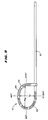
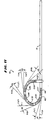
- Fig. 1 is a view of a catheter-type probe that carries a flexible ablating element comprising an array of spaced apart coil electrodes.
- Fig. 2 is an enlarged view of the array of spaced apart coil electrodes carried by the probe shown in Fig. 1.
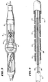
- Fig. 3 is an enlarged view of the handle of the probe shown in Fig. 1, with portions broken away and in section, showing the steering mechanism for flexing the ablating element.
- Fig. 4 is an enlarged side section view of the ablating element further showing the steering mechanism for flexing the ablating element.
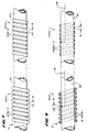
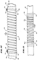
- Figs. 5 and 6 are, respectively, side and side section views of tightly wrapped coil electrodes;
- Figs. 7 and 8 are, respectively, side and side section views of spaced apart windings of round and flat coil electrodes;
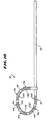
- Fig. 9 is a diagrammatic view of a flexible coil electrode element showing two dimensions that help characterize the flexibility of the electrode element in terms of its shape.
- Fig. 10 is a diagrammatic view of a flexible coil electrode element showing dimensions that help characterize the flexibility of the electrode element in terms of its ability to form tight curves of small radii.
- Fig. 11 is a diagrammatic view of a flexible coil electrode element showing dimensions that help characterize the flexibility of the electrode element in terms of its ability to achieve uniform intimate contact against heart tissue;
- Fig. 12 is a side view of a multiple zone flexible coil electrode, which provides enhanced flexibility as well accommodates placement of temperature sensing elements;
- Fig. 13 is a side view of an alternative embodiment of a multiple zone flexible coil electrode;
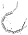
- Fig. 14 is a side view of an ablation element carrying individual coil electrodes that are not sufficiently flexible to conform to the desired curve of the element, causing gaps in tissue contact;
- Fig. 15 is a side view of an ablation element carrying individual coil electrodes that are sufficiently flexible to conform to the desired curve of the element, creating uniform tissue contact along the length of the element;
-
- Figures 1-11 and 14 as well as the corresponding text in the description do not define embodiments of the invention.
- This specification discloses multiple electrode structures that embody aspects of the invention. This specification also discloses tissue ablation systems using multiple temperature sensing elements that embody other aspects of the invention. The illustrated and preferred embodiments discuss these structures, and systems in the context of catheter-based cardiac ablation. That is because these structures, and systems are well suited for use in the field of cardiac ablation.
- Still, it should be appreciated that the invention is applicable for use in other tissue ablation applications. For example, the various aspects of the invention have application in procedures for ablating tissue in the prostrate, brain, gall bladder, uterus, and other regions of the body, using systems that are not necessarily catheter-based.
- Figs. 1 and 2 show a
flexible ablating element 10 that may be used to make lesions within the heart. - The
element 10 is carried at the distal end of acatheter body 12 of aprobe 14. Theprobe 14 includes ahandle 16 at the proximal end of thecatheter body 12. Thehandle 16 andcatheter body 12 carry asteering mechanism 18 for selectively bending or flexing the ablatingelement 10 in two opposite directions, as Figs. 1 and 2 show. - The
steering mechanism 18 can vary. In the illustrated embodiment (see Figs. 3 and 4), thesteering mechanism 18 includes a rotatingcam wheel 20 with an external steering lever 22 (also see Fig. 1) carried by thehandle 16. As Fig. 3 shows, thecam wheel 20 holds the proximal ends of right and leftsteering wires 24. Thewires 24 pass through thecatheter body 12 and connect to the left and right sides of a resilient bendable wire or leaf spring 26 (see Fig. 4) supported at the distal end of thecatheter body 12. - Further details of this and other types of steering mechanisms for the
ablating element 10 are shown in Lundquist and Thompson U.S. Pat. No. 5,254,088. - As Fig. 1 shows, forward movement of the steering
lever 22 flexes or curves the ablatingelement 10 in one direction. Rearward movement of the steeringlever 22 flexes or curves the ablatingelement 10 in the opposite. - Various access techniques can be used to introduce the
probe 14 into the desired region of the heart. For example, to enter the right atrium, the physician can direct theprobe 14 through a conventional vascular introducer through the femoral vein. For entry into the left atrium, the physician can direct theprobe 14 through a conventional vascular introducer retrograde through the aortic and mitral valves. - Alternatively, the physician can use the delivery system shown in U.S. Pat. No. 5,636,634, entitled "Systems and Methods Using Guide Sheaths for Introducing, Deploying, and Stabilizing Cardiac Mapping and Ablation Probes."
- The physician can verify intimate contact between the
element 10 and heart tissue using conventional pacing and sensing techniques. Once the physician establishes intimate contact with tissue in the desired heart region, the physician applies ablating energy to theelement 10. The type of ablating energy delivered to theelement 10 can vary. In the illustrated and preferred embodiment, theelement 10 transmits electromagnetic ablating energy with a frequency below about 1.0 GHz. This type of ablating energy, which is referred to as radio frequency energy, heats tissue, mostly ohmically, without electrically stimulating it. Alternatively, the element can transmit electromagnetic ablating energy with a frequency above 1.0 GHz. This type of ablating energy, which is referred to as microwave energy, produces both ohmic and dielectric tissue heating effects. - The ablating
element 10 can be conditioned to form elongated lesion patterns. These elongated lesion patterns can be continuous and extend along a straight line or along a curve. Elongated lesion patterns can be used to treat, for example, atrial fibrillation. - Fig. 2 shows one embodiment of the
flexible ablating element 10. In this embodiment, aflexible body 42 carries on its exterior surface an array of spaced apart, generallyflexible electrodes 44. In this embodiment, eachelectrode 44 comprises wire wound in relatively tight spiral coils. - The
flexible body 42 is made of a polymeric, electrically nonconductive material, like polyethylene or polyurethane. It is thebody 42 that carries within it the resilient bendable wire orleaf spring 26 with attachedsteering wires 24, as Fig. 4 shows, for flexing thebody 42 and, with it, the array ofelectrodes 44. - The
coil electrodes 44 are made of electrically conducting wire material. Copper alloy, platinum, or stainless steel 304, 0303, 17-7 can be used. Drawn, filled tubing comprising a stainless steel outer tubing with a platinum or silver inner core can also be used. The electrically conducting wire material of thecoil electrodes 44 can be coated with platinum-iridium or gold to improve its conduction properties and biocompatibility. - The
coil electrodes 44 can be made of closely wound, generally cylindrical wire, as the coil 44(a) shown in Figs. 5 and 6. Preferably, thecoil electrodes 44 are made of wound wire having a flat, or rectangular, cross section, as the coil 44(b) shown in Figs. 5 and 6. Wire having a flat cross section is preferred for several reasons. - First, using wire having a flat cross section, the tissue contact surface area of the resulting coil electrode 44(b) can be increased in an axial direction (i.e., along the body 42) without increasing the outside diameter of the electrode 44(b). More compact and easily
deployable ablating elements 10 result. - Moreover, a wire having a flat cross section, when wound into a coil electrode 44(b), permits a more efficient transmission of radio frequency ablation energy. Efficient transmission of radio frequency ablation energy by a
coil electrode 44 requires keeping DC resistances between the point of electrical contact with the signal wire and any location on the coil at or below about 10 ohms. As resistances exceed about 10 ohms, the radio frequency current densities transmitted by thecoil electrode 44 decrease substantially with the distance from the electrical connection. Using wire having a flat cross section, it is possible to maintain the outside and inside diameters of the wound coil electrode 44(b), and still control resistances, solely by changing the width of the wire. Furthermore, as the width of the wire increases, so can the spacing between windings, decreasing the length of wire. - The overall flexibility of the
element 10 is important to consistently achieve intimate contact with heart tissue along the length of theelement 10 and heart tissue. Without intimate contact along the entire length of theelement 10, transmission of radio frequency energy lacks uniformity, thus resulting in undesired gaps in lesion patterns. Gaps in the lesion pattern are known to be proarrhythmic and can lead to atrial flutter. - The dynamic, nonlinear nature of the endocardium complicates the matter. To consistently create intimate tissue contact, the
ablation element 10 must have the capability to flexibly adapt to a wide range of contours and interior spaces within the heart. - It has been discovered that closely wound coil electrodes 44(a) and 44(b) shown in Fig. 5 and 6, do not always provide intimate tissue contact along the length of the
element 10. Arrays of closely wound coil electrodes 44(a) and 44(b) often lack the flexibility to be easily bent into tight curves, having small curve radii. The individual coil electrodes 44(a) and 44(b) along the length of theelement 10 often do not bend uniformly. Some coil electrodes 44(a) and 44(b) within the array retain straight, tangential profiles, particularly in the regions where the bend in the desired curve is most acute. Steering difficulties and gaps in lesion patterns may result. - It has been discovered that the flexibility and performance of
elements 10 comprising arrays ofwound coil electrodes 44 can be significantly enhanced by spacing the wire windings in a prescribed way. Figs. 7 and 8 show a preferred embodiment of theablating element 10 incorporating this discovery. - In this embodiment, the same
flexible body 42 carries on its exterior surface an array of spaced apart lengths of wound, helical coils forming electrodes, designated 44(c) and 44(d) in Figs. 7 and 8. Unlike the closely spaced wire windings shown in Figs. 5 and 6, in Figs. 7 and 8, the wire windings in each coil electrode 44(c) and 44(d) have been spread apart by a distance D. This results from increasing the pitch of the individual wire windings forming the coil electrodes 44(c) and 44(d). - The spread-apart coil electrodes can be made of generally cylindrical wire, as the coil electrode 44(c) shown in Figs. 7 and 8. Still, however, it is preferred that the wire forming the spread-apart coil electrodes have a flat, or rectangular, cross section, as the coil electrode 44(d) shown in Figs. 7 and 8. The same reasons set forth above for preferring a flat cross section apply.
- The enhanced physical characteristics of the spread apart coil electrodes 44(c) and 44(d) in Figs. 7 and 8, when compared to the adjacent coil electrodes 44(a) and 44(b) in Figs. 5 and 6, can be demonstrated with respect to three physical functions. These functions differentiate flexibility among ablating
elements 10 comprising arrays of spaced apartcoil electrodes 44 in terms of flexed shape, degree of flexed curvature, and degree of tissue contact when flexed. - The first function (FS) (see Fig. 9) relates to the shape of a flexible
coil ablating element 10, when flexed. When flexed, the dimensions of thecurvilinear ablating element 10 can be expressed in terms of a perpendicular distance to the first bend (DP) and a maximum diameter (DM). The function FS can be expressed as a ratio of these two dimensions, as follows: - The closer FS is to 1, the more iso-radial, or circular, the flexed
structure 10 is. When FS ≈ 1, the flexedstructure 10 becomes circular. When FS < 1, the main axis of the ellipse is generally parallel to the axis of thecatheter body 12, as Fig. 9 shows. When FS > 1, the main axis of the ellipse is generally perpendicular to the axis of thecatheter body 12. - The second function (FT) (see Fig. 10) relates to the degree of curvature defined by the ablating
element 10, when flexed. As Fig. 10 shows, when theelement 10 is flexed, the individual coil electrode C(i) (i = 1 to N, where N is the number of electrodes) will each assume its own radius of curvature (RC(i)). FT can be expressed in terms of an average of the radii of curvature of the individual coil elements, as follows:
- The magnitude of FT points to how acutely the
element 10 can be flexed. As FT decreases, the smaller the overall radius of curvature for the entireflexed element 10 is, and the more theelement 10 is able to be flexed into a tight curve. - The third function Fc (see Fig. 11) relates to the uniformity of contact between tissue along the length of the flexed
element 10. When flexed, tangents can be drawn at the edges of adjacent coil electrodes C(i) and c(i+1), designated T(i) and T(i') in Fig. 11. The tangents T(i) and T(i') intersect for each electrode C(i) to form angles AT(i,i'). FC can be expressed as the average of the tangent angles along the length of the element, as follows:
-
Individual coil electrodes 44 that are not sufficiently flexible to conform to the desired curve of theelement 10 will form straight sections along the length of the flexedelement 10, as Fig. 14 shows. Tissue contact between successive straight sections will not be uniform. Gaps in contact (designated G in Fig. 14) can occur, creating gaps in lesions and undesired proarrhythmic effects. - The presence of straight sections will increase the magnitude of the tangent angles AT(i,i'). As Fc increases, the likelihood of non-uniform tissue contact along the flexed structure increases, as does the likelihood of gaps between lesions. Conversely, as FC decreases, the likelihood that the flexed
element 10 will conform uniformly along its length to the curvilinear contour of tissue, without straight sections and gaps (as Fig. 15 shows), increases. - Four
flexible ablation elements 10 were built for comparison, designated elements E1, E2, E3, and E4. Each ablation element E1-4 comprised six coil electrodes, each coil electrode being 12.5 mm in length. The coil electrodes were spaced apart by 2 mm. Each ablation element E1-4 used the same steering mechanism, as generally shown in Figs. 3 and 4 and as earlier described. - The coil electrodes in ablation elements E1 and E2 used round wire having an outside diameter of 0.31 mm (0.012 inch). In E1, the windings were adjacent, as represented by coil electrode 44(a) in Fig. 5. In E2, the windings were spaced apart, as represented by electrode 44(C) in Fig. 7. In E2, the distance D that the coil electrodes were spaced apart was 1/2 of the width of the wire, designated by the letter W in Fig. 7 (i.e., D = ½W).
- Ablation elements E3 and E4 used flat wire, 0.51 mm (0.020 inch) wide and 0.13 mm (0.005 inch) high. In E3, the windings were adjacent, as represented by electrode 44(b) in Fig. 5. In E4, the windings were spaced apart, as represented by electrode 44(d) in Fig. 7. In E4, the distance D that the coil electrodes were spaced apart was 1/2 of the width of the wire, also designated by the letter W in Fig. 7 (i.e., D = ½W).
- The physical characteristics FS; FT; and FC of the ablation elements E1, E2, E3, and E4 were tested. The following Tables summarize the test results:
FS DP cm(inch) DM cm(inch) FS E1
Round/Tight2.67 (1.05) 3.00 (1.18) 1.12 E2
Round/Spread2.18 (0.86) 2.41 (0.95) 1.11 E3
Flat/Tight2.34 (0.92) 2.82 (1.11) 1.21 E4
Flat/Spread1.75 (0.69) 1.96 (0.77) 1.12 FT FT cm(inch) E1 3.12 ± 1.24 Round/Tight (1.23 ± 0.49) E2 1.40 ± 0.61 Round/Spread (0.55 ± 0.24) E3 2.01 ± 0.97 Flat/Tight (0.79 ± 0.38) E4 1.33 ± 0.66 Flat/Spread (0.52 ± 0.26) FC FC E1
Round/Tight35° ± 8 E2
Round/Spread 26° ± 8 E3
Flat/Tight31° ± 11 E4
Flat/Spread 14° ± 6 - DC resistance (in ohms) was also measured for each ablation element, as set forth in the following Table:
Coil Resistance DC Resistance (Ohms) E1
Round/Tight3.32 ± 0.62 E2
Round/Spread2.68 ± 0.70 E3
Flat/Tight2.17 ± 0.16 E4
Flat/Spread1.67 ± 0.12 - The amount of force required to fully bend each ablation element E1; E2; E3; and E4 was measured (FBEND), as was the force to straighten out a each bent element (FUNBEND), as set forth in the following table:
BENDING FORCES FBEND N-m (lbf-in) FUNBEND N-m (lbf-in) E1 0.33 ± 0.007 0.33 ± 0.011 Round/Tight (2.90 ± 0.06) (2.90 ± 0.10) E2 0.29 ± 0.017 0.29 ± 0.014 Round/Spread (2.53 ± 0.15) (2.53 ± 0.12) E3 0.37 ± 0.007 0.37 ± 0.014 Flat/Tight (3.23 ± 0.06) (3.23 ± 0.12) E4 0.32 ± 0.017 0.32 ± 0.014 Flat/Spread (2.87 ± 0.15) (2.87 ± 0.12) - The foregoing example shows:
- (1) When the windings of the coil elements are brought farther apart (both round and flat wires) (Table 1), the absolute value of FS decreases, getting closer to 1.
- (2) For both round and flat wires, the values of FT and FC decrease when the windings of the coil elements are spaced further apart (Tables 2 and 3).
-
- Thus, regardless of flat or round coil configurations, spaced apart windings create an overall more flexible ablation element, which can more readily be bent into shapes having smaller radii of curvature and with greater likelihood of creating continuous zones of intimate contact with tissue, like that shown in Fig. 15. Moreover, in tightly wound coil configurations, adjacent windings can overlap during bending, which could potentially "pinch" the endocardium.
- The foregoing Example also shows that the spread apart flat wire configuration (E4) achieves the lowest FC (Table 3), and thus presents the highest likelihood of a conformal curve against tissue. The force to achieve a curve using the spread flat wire configuration E4 is greater than a spread round wire (E2) (Table 5), but the curve for the spread flat wire configuration (E4) is "tighter" and thus better than for the spread round wire configuration (E2) (Table 2).
- The foregoing Example demonstrates the mechanical benefits of separating the windings in the coils.
- It has been determined that the benefits of greater flexibility arose when the distance D between the windings is at least 1/5 of the width W of the wound wire. It has been determined that spacing of less than 1/5 of the width W of the wound wire leads to significantly less flexibility, with greater potential for pinching tissue between the windings. The most preferred distance D is believed to be about 1/2 of the width W of the wound wire.
- How far apart the windings should be spread to achieve the benefits of greater flexibility depends largely upon the desired heating effect. If additive heating effects between adjacent windings are desired to form continuous lesions between the windings, the upper spacing limit becomes the distance at which the desired additive heating effect is observed to diminish. The diminishing of the additive heating effect can be determined empirically or mathematically under the desired operating conditions and geometries.
- Various ways to control the characteristics of lesions formed by the
ablating elements 10 are disclosed in detail in U.S. Patent No. 6,106,522, entitled "Systems and Methods for Forming Elongated Lesion Patterns in Body Tissue Using Straight or Curvilinear Electrode Elements" and in U.S. Patent No. 5,810,802, entitled "Systems and Methods for Controlling Tissue Ablation Using Multiple Temperature Sensing Elements." - Above-identified U.S. Patent No. 5,810,802 shows the use of temperature sensing elements to measure temperatures along the length of the
ablation element 10. As disclosed in this prior application, the positioning of the temperature sensing elements on theelectrode elements 10 is important for achieving reliable temperature sensing, particularly when the length of an individual coil on theelement 10 exceeds about 10 mm, as contemplated in the preferred embodiment of this application. - Fig. 12 shows a preferred embodiment of a
coil electrode 50 designed for enhanced flexibility as well as to accommodate optimal placement oftemperature sensing elements 52. As Fig. 12 shows, thecoil electrode 50 comprises twozones - The
first zone 54 represents the majority of theelectrode 50, occupying its entire mid portion. Thefirst zone 54 comprises spaced apart windings to provide enhanced flexibility, as already described. - The
second zone 56 occupies each edge of thecoil electrode 50. Thesecond zone 56 comprises a region where the windings are closely adjacent to each other. The closeness of the windings provides a support structure for thetemperature sensing element 52. - As Fig. 12 shows, the
temperature sensing elements 52 are threaded up through the windings in eachsecond zone 56 to lay upon its exterior surface. eachsecond zone 56 to lay upon its exterior surface. In the illustrated embodiment, thesensing elements 52 comprise thermocouples, and each is encapsulated in an epoxy orPTFE coating 58. However, thermistors can be used. - Preferably, as shown in phantom lines in Fig. 12, the
temperature sensing elements 52 can be secured to the inside surface of eachsecond zone 56. Still alternatively, thesensing elements 52 can be sandwiched between the inside surface of thesecond zones 56 and the underlyingflexible body 42. - The two zone structure of the
coil electrode 50 shown in Fig. 12 allows placement oftemperature sensing elements 52 at the side edges 60 of theelectrode 50. Theseedges 60 are where theelectrode 50 abuts the underlying, non-electrically-conductive support body 42. RF current densities are high at theseedges 60, because theedges 60 are regions where electrical conductivity is discontinuous. The resulting rise in current density at the electrode edges 60 generates localized regions of increased power density and, therefore, regions where higher temperatures exist. Given the elongated size of theelectrode 50,temperature sensing elements 52 should preferably be located in these edge regions where high localized temperatures are to be expected. The closely spaced windings at thesecond region 56 accommodate such placement, without detracting from the overall flexibility that thefirst region 54 provides. - In a preferred embodiment (as Fig. 12 shows), a
thin strip 66 of electrically insulating material (for example, an electrically nonconducting adhesive) is applied about thebody 42 immediately next to thesecond regions 56. It has been observed that the presence of this electricallynonconducting strip 66 helps to minimize the presence of edge effect currents, which tend to be more pronounced in coil electrodes than other electrode structures. - Fig. 13 shows an alternative embodiment of a
coil electrode 60 designed for enhanced flexibility as well as to accommodate optimal placement oftemperature sensing elements 52. Fig. 13 is similar to Fig. 12, in that thecoil electrode 60 comprises at least twozones interior zone 54 is generally uniform, maintaining a distance at least 1/5 of the width of the wire. In Fig. 13, the spacing D in theinterior zone 62 is at least 1/5 of the width of the wire, but the actual distance D varies along theinterior zone 62. As Fig. 13 shows, the spacing D in theinterior zone 62 decreases progressively from the mid point of thecoil 60 toward theedge zones 64, where the windings are closely spaced (i.e., less than 1/5 of the width of the wire) to supporttemperature sensing elements 52. Alternatively, the spacing D can vary along theinterior zone 62 in a random fashion, while still observing the minimum spacing of 1/5 of the width of the wire. Practically speaking, it is to be expected that the spacing D will not be perfectly uniform or perfectly progressive, but will vary along theinterior zone 62, because of normal tolerance deviations in the manufacturing process. - As Fig. 13 also shows, the interior zone 62 (or, in Fig. 12, zone 54) could also carry a
temperature sensing element 52. The use of a third, more centrally locatedtemperature sensing element 52 is preferred when temperature prediction algorithms are used, as disclosed in U.S. Patent No. 5,810,802, as previously identified.
Claims (13)
- A device for ablating body tissue comprising a support body (42), wire wound about the support body (42) in adjacent windings to form an elongated electrode (50) having at least one edge adjoining the support body (42), and a connection coupling the wire to a source of ablation energy for transmission by the elongated electrode (50) to ablate tissue, characterized by
the adjacent windings being spaced farther apart away from the at least one edge than at the at least one edge. - A device according to claim 1 wherein the wire has a rectilinear cross-section.
- A device according to claim 1 wherein the wire has a circular cross-section.
- A device according to claim 1 wherein spacing between the adjacent windings away from the at least one edge varies.
- A device according to claim 1 wherein spacing between the adjacent windings away from the at least one edge is generally uniform.
- A device according to claim 1, further comprising
at least one temperature sensing element (52) on the electrode (50). - A device according to claim 1, further comprising
a temperature sensing element (52) near the at least one edge of the electrode (50). - A device according to claim 1 wherein the wire has a width, and wherein the adjacent windings are spaced apart by at least 1/5 of the width of the wire except near the at least one edge, where the adjacent windings are spaced closer than 1/5 of the width of the wire.
- A device according to claim 1 wherein the wire has a width, and wherein the adjacent windings are spaced apart by about 1/2 the width of the wire except near the at least one edge, where the adjacent windings are spaced closer than 1/5 of the width of the wire.
- A device according to claim 1 wherein the connection couples the wire to a source of radio frequency ablation energy for transmission by the elongated electrode (50) to ablate tissue.
- A device according to claim 1, wherein the support body (42) has an axis and is flexible, the device further comprising an element in the support body (42) for flexing the support body (42) relative to the axis and, with it, the elongated electrode (50).
- A device according to claim 1 wherein the elongated electrode (50) defines a first elongated electrode (50), the device further comprising a second wire wound about the support body (42) in adjacent windings to form a second elongated electrode (50) having at least one edge adjoining the support body, (42), the adjacent windings being spaced closer together near the at least one edge than away from the at least one edge of the second elongated electrode (50), the first and second elongated electrodes (50) forming an array of two mutually spaced apart elongated electrodes (50).
- A device according to claim 1 wherein the at least one edge comprises a pair of edges and adjacent windings are spaced farther apart away from the edge portions than at the edges.
Applications Claiming Priority (3)
| Application Number | Priority Date | Filing Date | Title |
|---|---|---|---|
| US558131 | 1983-12-05 | ||
| US08/558,131 US5797905A (en) | 1994-08-08 | 1995-11-13 | Flexible tissue ablation elements for making long lesions |
| PCT/US1996/018101 WO1997017904A1 (en) | 1995-11-13 | 1996-11-08 | Flexible tissue ablation elements for making long lesions |
Publications (3)
| Publication Number | Publication Date |
|---|---|
| EP0955917A1 EP0955917A1 (en) | 1999-11-17 |
| EP0955917A4 EP0955917A4 (en) | 1999-11-17 |
| EP0955917B1 true EP0955917B1 (en) | 2002-06-12 |
Family
ID=24228339
Family Applications (1)
| Application Number | Title | Priority Date | Filing Date |
|---|---|---|---|
| EP96939661A Expired - Lifetime EP0955917B1 (en) | 1995-11-13 | 1996-11-08 | Flexible tissue ablation elements for making long lesions |
Country Status (7)
| Country | Link |
|---|---|
| US (1) | US5797905A (en) |
| EP (1) | EP0955917B1 (en) |
| JP (1) | JP3756522B2 (en) |
| CA (1) | CA2237563C (en) |
| DE (1) | DE69621845T2 (en) |
| ES (1) | ES2176512T3 (en) |
| WO (1) | WO1997017904A1 (en) |
Families Citing this family (170)
| Publication number | Priority date | Publication date | Assignee | Title |
|---|---|---|---|---|
| US6113591A (en) * | 1994-06-27 | 2000-09-05 | Ep Technologies, Inc. | Systems and methods for sensing sub-surface temperatures in body tissue |
| US6245068B1 (en) | 1994-08-08 | 2001-06-12 | Scimed Life Systems, Inc. | Resilient radiopaque electrophysiology electrodes and probes including the same |
| US5814029A (en) * | 1994-11-03 | 1998-09-29 | Daig Corporation | Guiding introducer system for use in ablation and mapping procedures in the left ventricle |
| US6053912A (en) * | 1995-05-01 | 2000-04-25 | Ep Techonologies, Inc. | Systems and methods for sensing sub-surface temperatures in body tissue during ablation with actively cooled electrodes |
| US6030379A (en) * | 1995-05-01 | 2000-02-29 | Ep Technologies, Inc. | Systems and methods for seeking sub-surface temperature conditions during tissue ablation |
| DE29519651U1 (en) * | 1995-12-14 | 1996-02-01 | Muntermann Axel | Device for linear radio frequency catheter ablation of endomyocardial tissue |
| US7052493B2 (en) | 1996-10-22 | 2006-05-30 | Epicor Medical, Inc. | Methods and devices for ablation |
| DE19721362B4 (en) * | 1997-04-01 | 2011-05-26 | Axel Muntermann | Device and calibration method for catheter ablation |
| US6024740A (en) | 1997-07-08 | 2000-02-15 | The Regents Of The University Of California | Circumferential ablation device assembly |
| US5971983A (en) * | 1997-05-09 | 1999-10-26 | The Regents Of The University Of California | Tissue ablation device and method of use |
| US6012457A (en) | 1997-07-08 | 2000-01-11 | The Regents Of The University Of California | Device and method for forming a circumferential conduction block in a pulmonary vein |
| US6042590A (en) * | 1997-06-16 | 2000-03-28 | Novomedics, Llc | Apparatus and methods for fallopian tube occlusion |
| US5938660A (en) | 1997-06-27 | 1999-08-17 | Daig Corporation | Process and device for the treatment of atrial arrhythmia |
| US6251109B1 (en) | 1997-06-27 | 2001-06-26 | Daig Corporation | Process and device for the treatment of atrial arrhythmia |
| US6164283A (en) | 1997-07-08 | 2000-12-26 | The Regents Of The University Of California | Device and method for forming a circumferential conduction block in a pulmonary vein |
| US6547788B1 (en) * | 1997-07-08 | 2003-04-15 | Atrionx, Inc. | Medical device with sensor cooperating with expandable member |
| US6652515B1 (en) | 1997-07-08 | 2003-11-25 | Atrionix, Inc. | Tissue ablation device assembly and method for electrically isolating a pulmonary vein ostium from an atrial wall |
| US6245064B1 (en) | 1997-07-08 | 2001-06-12 | Atrionix, Inc. | Circumferential ablation device assembly |
| US6514249B1 (en) | 1997-07-08 | 2003-02-04 | Atrionix, Inc. | Positioning system and method for orienting an ablation element within a pulmonary vein ostium |
| US6500174B1 (en) | 1997-07-08 | 2002-12-31 | Atrionix, Inc. | Circumferential ablation device assembly and methods of use and manufacture providing an ablative circumferential band along an expandable member |
| US6080151A (en) | 1997-07-21 | 2000-06-27 | Daig Corporation | Ablation catheter |
| US6464699B1 (en) | 1997-10-10 | 2002-10-15 | Scimed Life Systems, Inc. | Method and apparatus for positioning a diagnostic or therapeutic element on body tissue and mask element for use with same |
| US6645200B1 (en) | 1997-10-10 | 2003-11-11 | Scimed Life Systems, Inc. | Method and apparatus for positioning a diagnostic or therapeutic element within the body and tip electrode for use with same |
| US6200315B1 (en) * | 1997-12-18 | 2001-03-13 | Medtronic, Inc. | Left atrium ablation catheter |
| US6522930B1 (en) | 1998-05-06 | 2003-02-18 | Atrionix, Inc. | Irrigated ablation device assembly |
| US6527767B2 (en) | 1998-05-20 | 2003-03-04 | New England Medical Center | Cardiac ablation system and method for treatment of cardiac arrhythmias and transmyocardial revascularization |
| US6302903B1 (en) * | 1998-07-07 | 2001-10-16 | Medtronic, Inc. | Straight needle apparatus for creating a virtual electrode used for the ablation of tissue |
| US6251128B1 (en) * | 1998-09-01 | 2001-06-26 | Fidus Medical Technology Corporation | Microwave ablation catheter with loop configuration |
| US6607502B1 (en) | 1998-11-25 | 2003-08-19 | Atrionix, Inc. | Apparatus and method incorporating an ultrasound transducer onto a delivery member |
| US6217528B1 (en) | 1999-02-11 | 2001-04-17 | Scimed Life Systems, Inc. | Loop structure having improved tissue contact capability |
| EP2289448B1 (en) | 1999-05-11 | 2013-03-13 | Atrionix, Inc. | Tissue ablation system including a balloon anchor wire |
| US6758830B1 (en) | 1999-05-11 | 2004-07-06 | Atrionix, Inc. | Catheter positioning system |
| WO2001037723A2 (en) | 1999-11-22 | 2001-05-31 | Boston Scientific Limited | Loop structures for supporting diagnostic and therapeutic elements in contact with body tissue |
| US6645199B1 (en) | 1999-11-22 | 2003-11-11 | Scimed Life Systems, Inc. | Loop structures for supporting diagnostic and therapeutic elements contact with body tissue and expandable push devices for use with same |
| US6795721B2 (en) | 2000-01-27 | 2004-09-21 | Biosense Webster, Inc. | Bidirectional catheter having mapping assembly |
| US7570982B2 (en) * | 2000-01-27 | 2009-08-04 | Biosense Webster, Inc. | Catheter having mapping assembly |
| US6711428B2 (en) * | 2000-01-27 | 2004-03-23 | Biosense Webster, Inc. | Catheter having mapping assembly |
| US6628976B1 (en) | 2000-01-27 | 2003-09-30 | Biosense Webster, Inc. | Catheter having mapping assembly |
| US6607555B2 (en) | 2000-02-15 | 2003-08-19 | Eva Corporation | Delivery catheter assembly and method of securing a surgical component to a vessel during a surgical procedure |
| US6558385B1 (en) | 2000-09-22 | 2003-05-06 | Tissuelink Medical, Inc. | Fluid-assisted medical device |
| US6689131B2 (en) | 2001-03-08 | 2004-02-10 | Tissuelink Medical, Inc. | Electrosurgical device having a tissue reduction sensor |
| US8048070B2 (en) | 2000-03-06 | 2011-11-01 | Salient Surgical Technologies, Inc. | Fluid-assisted medical devices, systems and methods |
| EP1946716B1 (en) | 2000-03-06 | 2017-07-19 | Salient Surgical Technologies, Inc. | Fluid delivery system and controller for electrosurgical devices |
| US7811282B2 (en) | 2000-03-06 | 2010-10-12 | Salient Surgical Technologies, Inc. | Fluid-assisted electrosurgical devices, electrosurgical unit with pump and methods of use thereof |
| US20020054924A1 (en) | 2000-04-13 | 2002-05-09 | Leahy Margaret M. | Novel compositions derived from cranberry and grapefruit and therapeutic uses therefor |
| AU6321301A (en) | 2000-05-16 | 2001-11-26 | Atrionix Inc | Apparatus and method incorporating an ultrasound transducer onto a delivery member |
| ATE290827T1 (en) | 2000-06-13 | 2005-04-15 | Atrionix Inc | SURGICAL ABLATION PROBE FOR FORMING AN ANNUAL LESION |
| US7789876B2 (en) * | 2000-08-14 | 2010-09-07 | Tyco Healthcare Group, Lp | Method and apparatus for positioning a catheter relative to an anatomical junction |
| US6669692B1 (en) * | 2000-08-21 | 2003-12-30 | Biosense Webster, Inc. | Ablation catheter with cooled linear electrode |
| US6942661B2 (en) | 2000-08-30 | 2005-09-13 | Boston Scientific Scimed, Inc. | Fluid cooled apparatus for supporting diagnostic and therapeutic elements in contact with tissue |
| US6926669B1 (en) * | 2000-10-10 | 2005-08-09 | Medtronic, Inc. | Heart wall ablation/mapping catheter and method |
| US6475179B1 (en) | 2000-11-10 | 2002-11-05 | New England Medical Center | Tissue folding device for tissue ablation, and method thereof |
| US6916306B1 (en) | 2000-11-10 | 2005-07-12 | Boston Scientific Scimed, Inc. | Steerable loop structures for supporting diagnostic and therapeutic elements in contact with body tissue |
| US6564096B2 (en) | 2001-02-28 | 2003-05-13 | Robert A. Mest | Method and system for treatment of tachycardia and fibrillation |
| US6827714B2 (en) | 2001-03-07 | 2004-12-07 | Scimed Life Systems, Inc. | Internal indifferent electrode device for use with lesion creation apparatus and method of forming lesions using the same |
| EP1435867B1 (en) | 2001-09-05 | 2010-11-17 | Salient Surgical Technologies, Inc. | Fluid-assisted medical devices and systems |
| US6939350B2 (en) | 2001-10-22 | 2005-09-06 | Boston Scientific Scimed, Inc. | Apparatus for supporting diagnostic and therapeutic elements in contact with tissue including electrode cooling device |
| US7785324B2 (en) | 2005-02-25 | 2010-08-31 | Endoscopic Technologies, Inc. (Estech) | Clamp based lesion formation apparatus and methods configured to protect non-target tissue |
| US7753908B2 (en) * | 2002-02-19 | 2010-07-13 | Endoscopic Technologies, Inc. (Estech) | Apparatus for securing an electrophysiology probe to a clamp |
| US7674258B2 (en) | 2002-09-24 | 2010-03-09 | Endoscopic Technologies, Inc. (ESTECH, Inc.) | Electrophysiology electrode having multiple power connections and electrophysiology devices including the same |
| US6907298B2 (en) * | 2002-01-09 | 2005-06-14 | Medtronic, Inc. | Method and apparatus for imparting curves in implantable elongated medical instruments |
| US20030158548A1 (en) | 2002-02-19 | 2003-08-21 | Phan Huy D. | Surgical system including clamp and apparatus for securing an energy transmission device to the clamp and method of converting a clamp into an electrophysiology device |
| US6932816B2 (en) | 2002-02-19 | 2005-08-23 | Boston Scientific Scimed, Inc. | Apparatus for converting a clamp into an electrophysiology device |
| US6733499B2 (en) * | 2002-02-28 | 2004-05-11 | Biosense Webster, Inc. | Catheter having circular ablation assembly |
| US20040106896A1 (en) * | 2002-11-29 | 2004-06-03 | The Regents Of The University Of California | System and method for forming a non-ablative cardiac conduction block |
| US6866662B2 (en) | 2002-07-23 | 2005-03-15 | Biosense Webster, Inc. | Ablation catheter having stabilizing array |
| US20040034365A1 (en) * | 2002-08-16 | 2004-02-19 | Lentz David J. | Catheter having articulation system |
| US8475455B2 (en) | 2002-10-29 | 2013-07-02 | Medtronic Advanced Energy Llc | Fluid-assisted electrosurgical scissors and methods |
| US7142903B2 (en) * | 2003-03-12 | 2006-11-28 | Biosense Webster, Inc. | Catheter with contractable mapping assembly |
| US20040186467A1 (en) * | 2003-03-21 | 2004-09-23 | Swanson David K. | Apparatus for maintaining contact between diagnostic and therapeutic elements and tissue and systems including the same |
| US20040249430A1 (en) * | 2003-06-03 | 2004-12-09 | Medtronic, Inc. | Implantable medical electrical lead |
| US7789877B2 (en) * | 2003-07-02 | 2010-09-07 | St. Jude Medical, Atrial Fibrillation Division, Inc. | Ablation catheter electrode arrangement |
| US7234225B2 (en) * | 2003-09-22 | 2007-06-26 | St. Jude Medical, Atrial Fibrillation Division, Inc. | Method for manufacturing medical device having embedded traces and formed electrodes |
| US8147486B2 (en) * | 2003-09-22 | 2012-04-03 | St. Jude Medical, Atrial Fibrillation Division, Inc. | Medical device with flexible printed circuit |
| US7229437B2 (en) * | 2003-09-22 | 2007-06-12 | St. Jude Medical, Atrial Fibrillation Division, Inc. | Medical device having integral traces and formed electrodes |
| US7435248B2 (en) * | 2003-09-26 | 2008-10-14 | Boston Scientific Scimed, Inc. | Medical probes for creating and diagnosing circumferential lesions within or around the ostium of a vessel |
| WO2005032651A1 (en) * | 2003-10-02 | 2005-04-14 | Medtronic, Inc. | Implantable medical lead and method of manufacture |
| US20050119653A1 (en) * | 2003-12-02 | 2005-06-02 | Swanson David K. | Surgical methods and apparatus for forming lesions in tissue and confirming whether a therapeutic lesion has been formed |
| US7608072B2 (en) * | 2003-12-02 | 2009-10-27 | Boston Scientific Scimed, Inc. | Surgical methods and apparatus for maintaining contact between tissue and electrophysiology elements and confirming whether a therapeutic lesion has been formed |
| US8052676B2 (en) | 2003-12-02 | 2011-11-08 | Boston Scientific Scimed, Inc. | Surgical methods and apparatus for stimulating tissue |
| US8002770B2 (en) | 2003-12-02 | 2011-08-23 | Endoscopic Technologies, Inc. (Estech) | Clamp based methods and apparatus for forming lesions in tissue and confirming whether a therapeutic lesion has been formed |
| JP2007519498A (en) * | 2004-01-30 | 2007-07-19 | エヌエムティー メディカル, インコーポレイティッド | Devices, systems, and methods for closure of cardiac openings |
| US7933661B2 (en) * | 2004-02-04 | 2011-04-26 | Medtronic, Inc. | Lead retention means |
| US7727232B1 (en) | 2004-02-04 | 2010-06-01 | Salient Surgical Technologies, Inc. | Fluid-assisted medical devices and methods |
| US7371233B2 (en) * | 2004-02-19 | 2008-05-13 | Boston Scientific Scimed, Inc. | Cooled probes and apparatus for maintaining contact between cooled probes and tissue |
| DE102004014753B3 (en) * | 2004-03-25 | 2005-11-24 | Epcos Ag | Ceramic element e.g. for temperature measurement over high temperature conductor, has body, connection ports with electrical inlets attached to it and element body has connection ports and are soldered on ends of the inlets in glass body |
| US8007495B2 (en) * | 2004-03-31 | 2011-08-30 | Biosense Webster, Inc. | Catheter for circumferential ablation at or near a pulmonary vein |
| US7824408B2 (en) | 2004-08-05 | 2010-11-02 | Tyco Healthcare Group, Lp | Methods and apparatus for coagulating and/or constricting hollow anatomical structures |
| US7549988B2 (en) | 2004-08-30 | 2009-06-23 | Boston Scientific Scimed, Inc. | Hybrid lesion formation apparatus, systems and methods |
| US20070016272A1 (en) | 2004-09-27 | 2007-01-18 | Thompson Russell B | Systems and methods for treating a hollow anatomical structure |
| US20060089637A1 (en) | 2004-10-14 | 2006-04-27 | Werneth Randell L | Ablation catheter |
| US8617152B2 (en) | 2004-11-15 | 2013-12-31 | Medtronic Ablation Frontiers Llc | Ablation system with feedback |
| US7429261B2 (en) | 2004-11-24 | 2008-09-30 | Ablation Frontiers, Inc. | Atrial ablation catheter and method of use |
| US7468062B2 (en) | 2004-11-24 | 2008-12-23 | Ablation Frontiers, Inc. | Atrial ablation catheter adapted for treatment of septal wall arrhythmogenic foci and method of use |
| US7862561B2 (en) * | 2005-01-08 | 2011-01-04 | Boston Scientific Scimed, Inc. | Clamp based lesion formation apparatus with variable spacing structures |
| US7776033B2 (en) * | 2005-01-08 | 2010-08-17 | Boston Scientific Scimed, Inc. | Wettable structures including conductive fibers and apparatus including the same |
| US7727231B2 (en) | 2005-01-08 | 2010-06-01 | Boston Scientific Scimed, Inc. | Apparatus and methods for forming lesions in tissue and applying stimulation energy to tissue in which lesions are formed |
| US7862562B2 (en) * | 2005-02-25 | 2011-01-04 | Boston Scientific Scimed, Inc. | Wrap based lesion formation apparatus and methods configured to protect non-target tissue |
| US7892228B2 (en) * | 2005-02-25 | 2011-02-22 | Boston Scientific Scimed, Inc. | Dual mode lesion formation apparatus, systems and methods |
| US8932208B2 (en) | 2005-05-26 | 2015-01-13 | Maquet Cardiovascular Llc | Apparatus and methods for performing minimally-invasive surgical procedures |
| US8016822B2 (en) | 2005-05-28 | 2011-09-13 | Boston Scientific Scimed, Inc. | Fluid injecting devices and methods and apparatus for maintaining contact between fluid injecting devices and tissue |
| US7850685B2 (en) | 2005-06-20 | 2010-12-14 | Medtronic Ablation Frontiers Llc | Ablation catheter |
| EP1909679B1 (en) | 2005-07-11 | 2013-11-20 | Medtronic Ablation Frontiers LLC | Low power tissue ablation system |
| US8945151B2 (en) * | 2005-07-13 | 2015-02-03 | Atricure, Inc. | Surgical clip applicator and apparatus including the same |
| WO2007014063A2 (en) | 2005-07-21 | 2007-02-01 | Vnus Medical Technologies, Inc. | Systems and methods for treating a hollow anatomical structure |
| US7879030B2 (en) * | 2005-07-27 | 2011-02-01 | St. Jude Medical, Atrial Fibrillation Division, Inc. | Multipolar, virtual-electrode catheter with at least one surface electrode and method for ablation |
| US8657814B2 (en) | 2005-08-22 | 2014-02-25 | Medtronic Ablation Frontiers Llc | User interface for tissue ablation system |
| US9259267B2 (en) | 2005-09-06 | 2016-02-16 | W.L. Gore & Associates, Inc. | Devices and methods for treating cardiac tissue |
| WO2007030433A2 (en) | 2005-09-06 | 2007-03-15 | Nmt Medical, Inc. | Removable intracardiac rf device |
| US20070088388A1 (en) * | 2005-09-19 | 2007-04-19 | Opolski Steven W | Delivery device for implant with dual attachment sites |
| US20070244371A1 (en) * | 2006-04-04 | 2007-10-18 | Nguyen Hoa D | Phlebectomy illumination device and methods |
| US20080161799A1 (en) * | 2006-12-29 | 2008-07-03 | Todd Stangenes | Position independent catheter |
| US8641704B2 (en) | 2007-05-11 | 2014-02-04 | Medtronic Ablation Frontiers Llc | Ablation therapy system and method for treating continuous atrial fibrillation |
| US10220187B2 (en) | 2010-06-16 | 2019-03-05 | St. Jude Medical, Llc | Ablation catheter having flexible tip with multiple flexible electrode segments |
| US11395694B2 (en) | 2009-05-07 | 2022-07-26 | St. Jude Medical, Llc | Irrigated ablation catheter with multiple segmented ablation electrodes |
| WO2009045265A1 (en) | 2007-10-05 | 2009-04-09 | Maquet Cardiovascular, Llc | Devices and methods for minimally-invasive surgical procedures |
| WO2009086448A1 (en) | 2007-12-28 | 2009-07-09 | Salient Surgical Technologies, Inc. | Fluid-assisted electrosurgical devices, methods and systems |
| JP5169551B2 (en) * | 2008-07-07 | 2013-03-27 | 日本ゼオン株式会社 | Electrode catheter |
| US9254168B2 (en) | 2009-02-02 | 2016-02-09 | Medtronic Advanced Energy Llc | Electro-thermotherapy of tissue using penetrating microelectrode array |
| JP5592409B2 (en) | 2009-02-23 | 2014-09-17 | サリエント・サージカル・テクノロジーズ・インコーポレーテッド | Fluid-assisted electrosurgical device and method of use thereof |
| US20100280328A1 (en) * | 2009-05-01 | 2010-11-04 | Tyco Healthcare Group, Lp | Methods and systems for illumination during phlebectomy procedures |
| JP5903043B2 (en) * | 2009-07-24 | 2016-04-13 | サピエンス ステアリング ブレイン スティムレーション ベー ヴィ | Medical tools for electrical stimulation |
| JP2013503723A (en) | 2009-09-08 | 2013-02-04 | サリエント・サージカル・テクノロジーズ・インコーポレーテッド | Cartridge assembly for electrosurgical devices, electrosurgical units, and methods of use thereof |
| WO2011112991A1 (en) | 2010-03-11 | 2011-09-15 | Salient Surgical Technologies, Inc. | Bipolar electrosurgical cutter with position insensitive return electrode contact |
| US9795765B2 (en) | 2010-04-09 | 2017-10-24 | St. Jude Medical International Holding S.À R.L. | Variable stiffness steering mechanism for catheters |
| US9173700B2 (en) | 2010-04-26 | 2015-11-03 | 9234438 Canada Inc. | Electrosurgical device and methods |
| US20110295249A1 (en) * | 2010-05-28 | 2011-12-01 | Salient Surgical Technologies, Inc. | Fluid-Assisted Electrosurgical Devices, and Methods of Manufacture Thereof |
| US9138289B2 (en) | 2010-06-28 | 2015-09-22 | Medtronic Advanced Energy Llc | Electrode sheath for electrosurgical device |
| US8906012B2 (en) | 2010-06-30 | 2014-12-09 | Medtronic Advanced Energy Llc | Electrosurgical devices with wire electrode |
| US8920417B2 (en) | 2010-06-30 | 2014-12-30 | Medtronic Advanced Energy Llc | Electrosurgical devices and methods of use thereof |
| US9023040B2 (en) | 2010-10-26 | 2015-05-05 | Medtronic Advanced Energy Llc | Electrosurgical cutting devices |
| US9427281B2 (en) | 2011-03-11 | 2016-08-30 | Medtronic Advanced Energy Llc | Bronchoscope-compatible catheter provided with electrosurgical device |
| EP2755574A1 (en) * | 2011-09-13 | 2014-07-23 | Stryker Corporation | Vaso-occlusive device |
| US9750565B2 (en) | 2011-09-30 | 2017-09-05 | Medtronic Advanced Energy Llc | Electrosurgical balloons |
| US8870864B2 (en) | 2011-10-28 | 2014-10-28 | Medtronic Advanced Energy Llc | Single instrument electrosurgery apparatus and its method of use |
| US9226792B2 (en) | 2012-06-12 | 2016-01-05 | Medtronic Advanced Energy Llc | Debridement device and method |
| WO2014010041A1 (en) * | 2012-07-11 | 2014-01-16 | テルモ株式会社 | Medical device |
| US11234760B2 (en) | 2012-10-05 | 2022-02-01 | Medtronic Advanced Energy Llc | Electrosurgical device for cutting and removing tissue |
| US11241267B2 (en) | 2012-11-13 | 2022-02-08 | Pulnovo Medical (Wuxi) Co., Ltd | Multi-pole synchronous pulmonary artery radiofrequency ablation catheter |
| CN102908191A (en) | 2012-11-13 | 2013-02-06 | 陈绍良 | Multipolar synchronous pulmonary artery radiofrequency ablation catheter |
| US10260181B2 (en) * | 2013-01-14 | 2019-04-16 | Lake Region Medical, Inc. | Directional mesh and associated systems |
| US20140200639A1 (en) * | 2013-01-16 | 2014-07-17 | Advanced Neuromodulation Systems, Inc. | Self-expanding neurostimulation leads having broad multi-electrode arrays |
| US9877707B2 (en) | 2013-03-07 | 2018-01-30 | Kyphon SÀRL | Systems and methods for track coagulation |
| EP3692906B1 (en) | 2013-03-15 | 2024-01-10 | Medtronic Holding Company Sàrl | A system for treating tissue |
| US9855404B2 (en) | 2013-05-03 | 2018-01-02 | St. Jude Medical International Holding S.À R.L. | Dual bend radii steering catheter |
| CN105636513B (en) | 2013-10-31 | 2020-05-12 | 波士顿科学医学有限公司 | Medical device for high resolution mapping using local matching |
| US10076258B2 (en) | 2013-11-01 | 2018-09-18 | Boston Scientific Scimed, Inc. | Cardiac mapping using latency interpolation |
| US10314647B2 (en) | 2013-12-23 | 2019-06-11 | Medtronic Advanced Energy Llc | Electrosurgical cutting instrument |
| US10813686B2 (en) | 2014-02-26 | 2020-10-27 | Medtronic Advanced Energy Llc | Electrosurgical cutting instrument |
| US9182758B1 (en) * | 2014-02-28 | 2015-11-10 | Michael H S Dunlop | Computer-implemented system and method for capability zone-based manufacturing quality control |
| WO2015134276A1 (en) | 2014-03-07 | 2015-09-11 | Boston Scientific Scimed, Inc. | Medical devices for mapping cardiac tissue |
| US9687167B2 (en) | 2014-03-11 | 2017-06-27 | Boston Scientific Scimed, Inc. | Medical devices for mapping cardiac tissue |
| JP6608924B2 (en) * | 2014-07-11 | 2019-11-20 | プルノヴォ メディカル (ウーシー) カンパニー リミテッド | Multipolar simultaneous pulmonary artery radiofrequency ablation catheter |
| US9974599B2 (en) | 2014-08-15 | 2018-05-22 | Medtronic Ps Medical, Inc. | Multipurpose electrosurgical device |
| JP6673598B2 (en) | 2014-11-19 | 2020-03-25 | エピックス セラピューティクス,インコーポレイテッド | High resolution mapping of tissue with pacing |
| SG11201703943VA (en) | 2014-11-19 | 2017-06-29 | Advanced Cardiac Therapeutics Inc | Ablation devices, systems and methods of using a high-resolution electrode assembly |
| EP3220844B1 (en) | 2014-11-19 | 2020-11-11 | EPiX Therapeutics, Inc. | Systems for high-resolution mapping of tissue |
| US11207130B2 (en) | 2015-02-18 | 2021-12-28 | Medtronic Xomed, Inc. | RF energy enabled tissue debridement device |
| US10376302B2 (en) | 2015-02-18 | 2019-08-13 | Medtronic Xomed, Inc. | Rotating electrical connector for RF energy enabled tissue debridement device |
| US10188456B2 (en) | 2015-02-18 | 2019-01-29 | Medtronic Xomed, Inc. | Electrode assembly for RF energy enabled tissue debridement device |
| US9636164B2 (en) | 2015-03-25 | 2017-05-02 | Advanced Cardiac Therapeutics, Inc. | Contact sensing systems and methods |
| US11389227B2 (en) | 2015-08-20 | 2022-07-19 | Medtronic Advanced Energy Llc | Electrosurgical device with multivariate control |
| US11051875B2 (en) | 2015-08-24 | 2021-07-06 | Medtronic Advanced Energy Llc | Multipurpose electrosurgical device |
| US10441339B2 (en) * | 2015-11-17 | 2019-10-15 | Medtronic Holding Company Sárl | Spinal tissue ablation apparatus, system, and method |
| US10716612B2 (en) | 2015-12-18 | 2020-07-21 | Medtronic Advanced Energy Llc | Electrosurgical device with multiple monopolar electrode assembly |
| CA3017269A1 (en) | 2016-03-15 | 2017-09-21 | Epix Therapeutics, Inc. | Improved devices, systems and methods for irrigated ablation |
| CN110809448B (en) | 2017-04-27 | 2022-11-25 | Epix疗法公司 | Determining properties of contact between catheter tip and tissue |
| WO2018204586A1 (en) * | 2017-05-05 | 2018-11-08 | Cryterion Medical, Inc. | Corewire for mapping catheter for intravascular catheter system |
| CN107349010A (en) * | 2017-07-07 | 2017-11-17 | 昆山雷盛医疗科技有限公司 | Radio frequency ablation probe and preparation method thereof |
| CN113729926B (en) * | 2019-12-27 | 2024-01-05 | 苏州恒瑞宏远医疗科技有限公司 | Radio frequency closure catheter and manufacturing method thereof |
Family Cites Families (8)
| Publication number | Priority date | Publication date | Assignee | Title |
|---|---|---|---|---|
| US4633889A (en) * | 1984-12-12 | 1987-01-06 | Andrew Talalla | Stimulation of cauda-equina spinal nerves |
| US4960133A (en) * | 1988-11-21 | 1990-10-02 | Brunswick Manufacturing Co., Inc. | Esophageal electrode |
| US5016808A (en) * | 1989-09-14 | 1991-05-21 | Cardiac Pacemakers, Inc. | Implantable tapered spiral endocardial lead for use in internal defibrillation |
| US5254088A (en) * | 1990-02-02 | 1993-10-19 | Ep Technologies, Inc. | Catheter steering mechanism |
| US5334193A (en) * | 1992-11-13 | 1994-08-02 | American Cardiac Ablation Co., Inc. | Fluid cooled ablation catheter |
| ES2260758T3 (en) * | 1993-10-14 | 2006-11-01 | Boston Scientific Limited | ELECTRODE ELEMENTS TO FORM INJURY PATTERNS. |
| US5545193A (en) * | 1993-10-15 | 1996-08-13 | Ep Technologies, Inc. | Helically wound radio-frequency emitting electrodes for creating lesions in body tissue |
| US5676662A (en) * | 1995-03-17 | 1997-10-14 | Daig Corporation | Ablation catheter |
-
1995
- 1995-11-13 US US08/558,131 patent/US5797905A/en not_active Expired - Lifetime
-
1996
- 1996-11-08 WO PCT/US1996/018101 patent/WO1997017904A1/en active IP Right Grant
- 1996-11-08 JP JP51898897A patent/JP3756522B2/en not_active Expired - Lifetime
- 1996-11-08 ES ES96939661T patent/ES2176512T3/en not_active Expired - Lifetime
- 1996-11-08 EP EP96939661A patent/EP0955917B1/en not_active Expired - Lifetime
- 1996-11-08 CA CA002237563A patent/CA2237563C/en not_active Expired - Lifetime
- 1996-11-08 DE DE69621845T patent/DE69621845T2/en not_active Expired - Lifetime
Also Published As
| Publication number | Publication date |
|---|---|
| CA2237563A1 (en) | 1997-05-22 |
| JP2000500363A (en) | 2000-01-18 |
| ES2176512T3 (en) | 2002-12-01 |
| EP0955917A1 (en) | 1999-11-17 |
| US5797905A (en) | 1998-08-25 |
| DE69621845T2 (en) | 2003-01-02 |
| CA2237563C (en) | 2003-06-17 |
| WO1997017904A1 (en) | 1997-05-22 |
| EP0955917A4 (en) | 1999-11-17 |
| DE69621845D1 (en) | 2002-07-18 |
| JP3756522B2 (en) | 2006-03-15 |
Similar Documents
| Publication | Publication Date | Title |
|---|---|---|
| EP0955917B1 (en) | Flexible tissue ablation elements for making long lesions | |
| US6030382A (en) | Flexible tissue ablatin elements for making long lesions | |
| WO1997017904A9 (en) | Flexible tissue ablation elements for making long lesions | |
| US7063682B1 (en) | Catheter distal assembly with pull wires | |
| US6203525B1 (en) | Catheterdistal assembly with pull wires | |
| US6048329A (en) | Catheter distal assembly with pull wires | |
| US6245068B1 (en) | Resilient radiopaque electrophysiology electrodes and probes including the same | |
| US6745080B2 (en) | Helical and pre-oriented loop structures for supporting diagnostic and therapeutic elements in contact with body tissue | |
| CA2176149C (en) | Electrode array catheter | |
| US6711444B2 (en) | Methods of deploying helical diagnostic and therapeutic element supporting structures within the body | |
| US6171306B1 (en) | Systems and methods for forming large lesions in body tissue using curvilinear electrode elements | |
| US6613046B1 (en) | Loop structures for supporting diagnostic and therapeutic elements in contact with body tissue | |
| US6542781B1 (en) | Loop structures for supporting diagnostic and therapeutic elements in contact with body tissue | |
| EP1383437B1 (en) | Helically shaped electrophysiology catheter | |
| US6471699B1 (en) | Systems and methods for forming elongated lesion patterns in body tissue using straight or curvilinear electrode elements | |
| US5680860A (en) | Mapping and/or ablation catheter with coilable distal extremity and method for using same | |
| US6217528B1 (en) | Loop structure having improved tissue contact capability | |
| EP1027090B1 (en) | Catheter distal assembly with pull wires |
Legal Events
| Date | Code | Title | Description |
|---|---|---|---|
| PUAI | Public reference made under article 153(3) epc to a published international application that has entered the european phase |
Free format text: ORIGINAL CODE: 0009012 |
|
| 17P | Request for examination filed |
Effective date: 19980612 |
|
| A4 | Supplementary search report drawn up and despatched |
Effective date: 19991001 |
|
| AK | Designated contracting states |
Kind code of ref document: A4 Designated state(s): DE ES FR GB IT NL SE Kind code of ref document: A1 Designated state(s): DE ES FR GB IT NL SE |
|
| 17Q | First examination report despatched |
Effective date: 20010403 |
|
| RAP1 | Party data changed (applicant data changed or rights of an application transferred) |
Owner name: BOSTON SCIENTIFIC LIMITED |
|
| GRAG | Despatch of communication of intention to grant |
Free format text: ORIGINAL CODE: EPIDOS AGRA |
|
| GRAG | Despatch of communication of intention to grant |
Free format text: ORIGINAL CODE: EPIDOS AGRA |
|
| GRAH | Despatch of communication of intention to grant a patent |
Free format text: ORIGINAL CODE: EPIDOS IGRA |
|
| GRAH | Despatch of communication of intention to grant a patent |
Free format text: ORIGINAL CODE: EPIDOS IGRA |
|
| GRAA | (expected) grant |
Free format text: ORIGINAL CODE: 0009210 |
|
| AK | Designated contracting states |
Kind code of ref document: B1 Designated state(s): DE ES FR GB IT NL SE |
|
| REG | Reference to a national code |
Ref country code: GB Ref legal event code: FG4D |
|
| RIC1 | Information provided on ipc code assigned before grant |
Free format text: 7A 61B 18/00 A, 7A 61B 18/12 B |
|
| REF | Corresponds to: |
Ref document number: 69621845 Country of ref document: DE Date of ref document: 20020718 |
|
| PG25 | Lapsed in a contracting state [announced via postgrant information from national office to epo] |
Ref country code: SE Free format text: LAPSE BECAUSE OF FAILURE TO SUBMIT A TRANSLATION OF THE DESCRIPTION OR TO PAY THE FEE WITHIN THE PRESCRIBED TIME-LIMIT Effective date: 20020912 |
|
| ET | Fr: translation filed | ||
| REG | Reference to a national code |
Ref country code: ES Ref legal event code: FG2A Ref document number: 2176512 Country of ref document: ES Kind code of ref document: T3 |
|
| PLBE | No opposition filed within time limit |
Free format text: ORIGINAL CODE: 0009261 |
|
| STAA | Information on the status of an ep patent application or granted ep patent |
Free format text: STATUS: NO OPPOSITION FILED WITHIN TIME LIMIT |
|
| 26N | No opposition filed |
Effective date: 20030313 |
|
| PGFP | Annual fee paid to national office [announced via postgrant information from national office to epo] |
Ref country code: NL Payment date: 20101025 Year of fee payment: 15 |
|
| PGFP | Annual fee paid to national office [announced via postgrant information from national office to epo] |
Ref country code: ES Payment date: 20101115 Year of fee payment: 15 |
|
| REG | Reference to a national code |
Ref country code: NL Ref legal event code: V1 Effective date: 20120601 |
|
| PG25 | Lapsed in a contracting state [announced via postgrant information from national office to epo] |
Ref country code: NL Free format text: LAPSE BECAUSE OF NON-PAYMENT OF DUE FEES Effective date: 20120601 |
|
| REG | Reference to a national code |
Ref country code: ES Ref legal event code: FD2A Effective date: 20130603 |
|
| PG25 | Lapsed in a contracting state [announced via postgrant information from national office to epo] |
Ref country code: ES Free format text: LAPSE BECAUSE OF NON-PAYMENT OF DUE FEES Effective date: 20111109 |
|
| REG | Reference to a national code |
Ref country code: FR Ref legal event code: CA Effective date: 20140513 |
|
| REG | Reference to a national code |
Ref country code: DE Ref legal event code: R082 Ref document number: 69621845 Country of ref document: DE Representative=s name: PFENNING MEINIG & PARTNER GBR, DE |
|
| REG | Reference to a national code |
Ref country code: DE Ref legal event code: R082 Ref document number: 69621845 Country of ref document: DE Representative=s name: PFENNING MEINIG & PARTNER GBR, DE |
|
| REG | Reference to a national code |
Ref country code: DE Ref legal event code: R082 Ref document number: 69621845 Country of ref document: DE Representative=s name: PFENNING, MEINIG & PARTNER MBB PATENTANWAELTE, DE Effective date: 20150202 Ref country code: DE Ref legal event code: R082 Ref document number: 69621845 Country of ref document: DE Representative=s name: PFENNING, MEINIG & PARTNER MBB PATENTANWAELTE, DE Effective date: 20140725 Ref country code: DE Ref legal event code: R082 Ref document number: 69621845 Country of ref document: DE Representative=s name: PFENNING MEINIG & PARTNER GBR, DE Effective date: 20150202 Ref country code: DE Ref legal event code: R082 Ref document number: 69621845 Country of ref document: DE Representative=s name: PFENNING MEINIG & PARTNER GBR, DE Effective date: 20140725 Ref country code: DE Ref legal event code: R081 Ref document number: 69621845 Country of ref document: DE Owner name: BOSTON SCIENTIFIC LIMITED, BM Free format text: FORMER OWNER: BOSTON SCIENTIFIC LTD., ST. MICHAEL, BARBADOS, BB Effective date: 20150202 |
|
| REG | Reference to a national code |
Ref country code: FR Ref legal event code: PLFP Year of fee payment: 20 |
|
| PGFP | Annual fee paid to national office [announced via postgrant information from national office to epo] |
Ref country code: FR Payment date: 20150629 Year of fee payment: 20 |
|
| PGFP | Annual fee paid to national office [announced via postgrant information from national office to epo] |
Ref country code: IT Payment date: 20151124 Year of fee payment: 20 Ref country code: DE Payment date: 20151103 Year of fee payment: 20 Ref country code: GB Payment date: 20151104 Year of fee payment: 20 |
|
| REG | Reference to a national code |
Ref country code: DE Ref legal event code: R071 Ref document number: 69621845 Country of ref document: DE |
|
| REG | Reference to a national code |
Ref country code: GB Ref legal event code: PE20 Expiry date: 20161107 |
|
| PG25 | Lapsed in a contracting state [announced via postgrant information from national office to epo] |
Ref country code: GB Free format text: LAPSE BECAUSE OF EXPIRATION OF PROTECTION Effective date: 20161107 |