EP0957798B1 - Spinal implant connection assembly - Google Patents
Spinal implant connection assembly Download PDFInfo
- Publication number
- EP0957798B1 EP0957798B1 EP96928858A EP96928858A EP0957798B1 EP 0957798 B1 EP0957798 B1 EP 0957798B1 EP 96928858 A EP96928858 A EP 96928858A EP 96928858 A EP96928858 A EP 96928858A EP 0957798 B1 EP0957798 B1 EP 0957798B1
- Authority
- EP
- European Patent Office
- Prior art keywords
- bolt
- rod
- connecting member
- washer
- interface
- Prior art date
- Legal status (The legal status is an assumption and is not a legal conclusion. Google has not performed a legal analysis and makes no representation as to the accuracy of the status listed.)
- Expired - Lifetime
Links
Images


Classifications
-
- A—HUMAN NECESSITIES
- A61—MEDICAL OR VETERINARY SCIENCE; HYGIENE
- A61B—DIAGNOSIS; SURGERY; IDENTIFICATION
- A61B17/00—Surgical instruments, devices or methods, e.g. tourniquets
- A61B17/56—Surgical instruments or methods for treatment of bones or joints; Devices specially adapted therefor
- A61B17/58—Surgical instruments or methods for treatment of bones or joints; Devices specially adapted therefor for osteosynthesis, e.g. bone plates, screws, setting implements or the like
- A61B17/68—Internal fixation devices, including fasteners and spinal fixators, even if a part thereof projects from the skin
- A61B17/70—Spinal positioners or stabilisers ; Bone stabilisers comprising fluid filler in an implant
- A61B17/7001—Screws or hooks combined with longitudinal elements which do not contact vertebrae
- A61B17/7035—Screws or hooks, wherein a rod-clamping part and a bone-anchoring part can pivot relative to each other
- A61B17/7037—Screws or hooks, wherein a rod-clamping part and a bone-anchoring part can pivot relative to each other wherein pivoting is blocked when the rod is clamped
-
- A—HUMAN NECESSITIES
- A61—MEDICAL OR VETERINARY SCIENCE; HYGIENE
- A61B—DIAGNOSIS; SURGERY; IDENTIFICATION
- A61B1/00—Instruments for performing medical examinations of the interior of cavities or tubes of the body by visual or photographical inspection, e.g. endoscopes; Illuminating arrangements therefor
- A61B1/00064—Constructional details of the endoscope body
- A61B1/00071—Insertion part of the endoscope body
- A61B1/0008—Insertion part of the endoscope body characterised by distal tip features
- A61B1/00085—Baskets
-
- A—HUMAN NECESSITIES
- A61—MEDICAL OR VETERINARY SCIENCE; HYGIENE
- A61B—DIAGNOSIS; SURGERY; IDENTIFICATION
- A61B17/00—Surgical instruments, devices or methods, e.g. tourniquets
- A61B17/56—Surgical instruments or methods for treatment of bones or joints; Devices specially adapted therefor
- A61B17/58—Surgical instruments or methods for treatment of bones or joints; Devices specially adapted therefor for osteosynthesis, e.g. bone plates, screws, setting implements or the like
- A61B17/68—Internal fixation devices, including fasteners and spinal fixators, even if a part thereof projects from the skin
- A61B17/70—Spinal positioners or stabilisers ; Bone stabilisers comprising fluid filler in an implant
- A61B17/7001—Screws or hooks combined with longitudinal elements which do not contact vertebrae
- A61B17/7035—Screws or hooks, wherein a rod-clamping part and a bone-anchoring part can pivot relative to each other
- A61B17/7038—Screws or hooks, wherein a rod-clamping part and a bone-anchoring part can pivot relative to each other to a different extent in different directions, e.g. within one plane only
-
- A—HUMAN NECESSITIES
- A61—MEDICAL OR VETERINARY SCIENCE; HYGIENE
- A61B—DIAGNOSIS; SURGERY; IDENTIFICATION
- A61B17/00—Surgical instruments, devices or methods, e.g. tourniquets
- A61B17/56—Surgical instruments or methods for treatment of bones or joints; Devices specially adapted therefor
- A61B17/58—Surgical instruments or methods for treatment of bones or joints; Devices specially adapted therefor for osteosynthesis, e.g. bone plates, screws, setting implements or the like
- A61B17/68—Internal fixation devices, including fasteners and spinal fixators, even if a part thereof projects from the skin
- A61B17/70—Spinal positioners or stabilisers ; Bone stabilisers comprising fluid filler in an implant
- A61B17/7001—Screws or hooks combined with longitudinal elements which do not contact vertebrae
- A61B17/7041—Screws or hooks combined with longitudinal elements which do not contact vertebrae with single longitudinal rod offset laterally from single row of screws or hooks
Definitions
- This invention relates generally to a spinal implant assembly, and more particularly to a spinal implant connection assembly.
- Spinal implant systems provide a rod for supporting the spine and properly positioning components of the spine for various treatment purposes.
- Bolts or screws are typically secured into the vertebrae for connection to the supporting rod. These bolts must frequently be positioned at various angles due to the anatomical structure of the patient, the physiological problem, and the preference of the physician. It is difficult to provide secure connection between the spinal support rod and these connecting bolts at various angles, and where there are differing distances between the rod and bolts and different heights relative to these components.
- US-A-5261909 shows an eye bolt with a head having an interface surface to engage an interface washer which has a further interface surface to engage a rod. Use of such a system will require the height of the eye bolt to be extremely accurately aligned.
- connection assembly which will securely engage a spinal support rod to connecting bolts.
- connection assembly which will provide for engagement of the spinal support rod to the connecting bolts where the connecting bolts are at a variety of angles relative to the vertical, taken when the patient is lying down.
- connection assembly which will allow connection between a spinal support rod and connecting bolts at a variety of vertical and horizontal distances between the rod and bolts.
- connection assembly for connecting a spinal implant rod to a spinal implant bolt which includes a rod connecting member having an aperture for receiving a portion of the rod and a bolt connecting member having an aperture for receiving a portion of the bolt.
- the rod connecting member and bolt connecting member are rotatably engaged to one another.
- a rod interface washer is positioned over a portion of the rod connecting member, and a bolt interface washer is positioned over a portion of the bolt connecting member.
- the rod interface washer and bolt interface washer are moveable in part between the rod connecting member and the bolt connecting member, the rod connecting washer being fixed against rotation relative to the rod connecting member and the bolt interface washer being fixed against rotation relative to the bolt interface washer.
- Structure extendable into at least one of the apertures is provided, so as to urge one of the rod and bolt toward the other, and to cause the washers to be pressed together between the rod and the bolt, preventing rotation of the rod interface washer and rod connecting member relative to the bolt interface washer and bolt connecting member, and securing the rod to the bolt.
- a slide-in pin assembly is used to rotatably engage the rod connecting member to the bolt connecting member.
- a partially open clasp can replace the enclosed aperture of the rod connecting member and/or the bolt connecting member.
- a wedge nut is used to urge the interface washer away from the bolt and toward the rod.
- the rod will be pressed outwardly against the rod connecting member and the bolt will be pressed outwardly against the bolt connecting member.
- a single washer takes the place of the rod interface washer and the bolt interface washer.
- This compound washer has engagement structure such as grooves on each side for engaging the rod and the bolt so as to prevent relative rotation of the rod connecting member and the bolt connecting member.
- the swivel assembly connection 10 comprises a rod connecting member 14 and a bolt connecting member 18.
- the rod connecting member 14 has an aperture 22 for receiving a rod in a spinal implant system.
- Structure for urging the rod within the aperture 24, such as the set screw 24, is provided through a suitable threaded opening in the rod connecting member 14 so as to be extendable into the aperture 22.
- the bolt connecting member 18 has an aperture 26 for receiving a bolt or screw of a spinal implant system.
- the rod connecting member 14 and bolt connecting member 18 are attached by a rotatable connection.
- the rotatable connection can be of any suitable design. It is preferable that the swivel connection have a snap-together construction to facilitate the assembly of the final device.
- the rod connecting member 14 can have a male protrusion 30 and the bolt connecting member 18 can have a corresponding female cavity formed in a neck 32.
- a flared end portion 36 of the male protrusion 30 can be provided to cooperate with a corresponding portion of the female cavity to provide snap-in engagement.
- the male protrusion 30 is preferably symmetrical about its long axis to facilitate rotation in the female cavity, and will thereby provide a swivel connection between the rod connecting member 14 and the bolt connecting member 18.
- the male and female connections could be provided by a threaded member, such as a screw, and a threaded opening in one of the rod connecting member 14 and the bolt connecting member 18.
- the screw would extend through an opening in one of the rod connecting member 14 and bolt connecting member 18 to connect to the threaded opening in the other member, so as to rotatably engage the two members together.
- the rod connecting member 14 can have a washer seat portion 40.
- a seat that is substantially rectangular in cross section is currently preferred, but the seat 40 can be of any suitable shape.
- a washer stop surface 44 can be provided by an enlarged portion of the rod connecting member 14.
- the bolt connecting member can have a washer seat 48 and a similar washer stop surface 52.
- An interface washer 60 according to the invention is shown in Figs. 3-5.
- the interface washer can be any of several suitable shapes, including the semi-oval shape that is depicted.
- One surface of the interface washer 60 has an engagement surface 62, which preferably has an engagement groove 64 for engaging a cylindrical rod, bolt or screw surface.
- the engagement groove 64 runs substantially diametrically through the oval washer.
- a central opening 68 in the washer corresponds in shape to the cross-sectional shape of the respective washer seat to which it is engaged, whether the washer seat 40 of the rod connecting member 14 or the washer seat 48 of the bolt connecting member 18.
- the corresponding openings and washer seats are of substantially rectangular shape, although this shape could vary and be of varying size, and could also be different for the washer seat 40 of the rod connecting member 14 and the washer seat 48 of the bolt connecting member 18.
- the interface washer 60 has a washer connection surface 66 opposite to the engagement surface 62.
- the washer connection surface 66 preferably includes structure for facilitating the engagement of the washer against rotational movement relative to another interface washer against which it is pressed.
- This engagement structure is preferably a plurality of variable angle ridges 72 which radiate from the rotational center of the interface washer 60, as will be explained below.
- the complete rotatable connection assembly 10 is shown in Figs. 6-7.
- a rod 80 is positioned in the aperture 22 of the rod connecting member 14.
- a post 84 of a bolt 88 that is connected to a screw portion 92 is positioned through the aperture 26 of the bolt connecting member 18. It will be appreciated that the screw 92 is typically oriented somewhat vertically into the spine when the patient is lying horizontally.
- the rod 80 extends somewhat horizontally along the length of the spine of the patient, again when the patient is lying.
- Two interface washers 60 are provided with the connection assembly of the invention.
- a first interface washer 60 is provided over the washer seat 40 of the rod connecting member 14.
- a second interface washer 96 preferably similar in construction to the interface washer 60, is positioned over the washer seat 48 of the bolt connecting member 18.
- the washer connection surfaces 66 of each washer face one another in the completed assembly.
- the bolt interface washer 96 is substantially identical to the rod interface washer 60, and includes an engagement groove 64, an opening 68, and variable angle surfaces 72.
- the variable angle surfaces 72 of the rod interface washer 60 and the bolt interface washer 96 face one another in the assembled swivel connection assembly. This permits mutual engagement of the rod interface washer 60 and the bolt interface washer 96.
- the rod interface washer 60 and bolt interface washer 96 are oriented substantially 180° to one another because of the orientation of the rod connecting member 14 and bolt connecting member 18.
- the width of the interface washers 60 and 96 is less than the distance between the respective washer stop surface 44 of the rod connecting member 14 and the washer stop surface 52 of the bolt connecting member 18. There is therefore some freedom of movement of the interface washers 60 and 96 between to the rod connecting member 14 and bolt connecting member 18. Also, because the variable angle surfaces 72 are non-engaged, the rod connecting member 14 and rod interface washer 60 can rotate freely with respect to the bolt connecting member 18 and the bolt interface washer 96.
- the aperture 22 of the rod connecting member 14 and aperture 26 of the bolt connecting member 18 are larger in dimension than the cross section of the rod 80 and bolt 88, such that movement of each within the respective aperture is possible.
- the flexibility of the invention in making a connection between the rod 80 and a plurality of bolts 88 is provided because the swivel assembly can be moved up and down over the portion 84 and horizontally over the rod 80, as can be seen from Figs. 6-7.
- the rod 80 and bolt 88 can be in differing angular positions, because the rod connecting member 14 and bolt connecting member 18 can rotate relative to each other.
- the linear distance between the rod 80 and bolt 88 can be adjusted because of the variability provided by the apertures 22 and 26.
- different sizes of spinal implant connection assemblies 10 according to the invention can be provided, and with different thicknesses of interface washers 60 and 96, such that differing distances between the rod 80 and bolt 88 can be accommodated.
- FIG. 8-11 The manner of connection of the spinal implant connection assembly 10 according to the invention to the rod 80 and the bolt 88 is depicted in Figs. 8-11.
- the set screw 24 is threaded into the aperture 22 (Fig. 8) where it contacts the side of the rod 80 and forces the rod 80 toward the bolt connecting member 18.
- the rod 80 contacts the rod interface washer 60, and preferably engages the engagement groove 64 as previously described. This will force the rod interface washer 60 against the bolt interface washer 96.
- variable angle surfaces 72 of each will engage to prevent further rotation of the rod connecting member 14 and bolt connecting member 18 relative to one another, because the rod interface washer 60 and bolt interface washer 96 are fixed relative to the respective rod connecting member 14 and bolt connecting member 18.
- the assembly becomes unitary and cannot swivel when they are engaged.
- the rod interface washer 60 and bolt interface washer 96 are forced further toward the bolt 88.
- the bolt 88 is engaged by the bolt interface washer 96, preferably by an engagement groove 64. This will force the bolt 88 against a lateral surface 90 of the aperture 26 to secure the bolt 88 in place.
- the entire assembly will thereby become locked against movement. Adjustments can be made by loosening the set screw 24 and then re-tightening the set screw when the preferred position has been located.
- FIG. 10 An X, Y, and Z axis are illustrated for purposes of reference.
- the bolt connecting member 18 Prior to fixation, the bolt connecting member 18 can move along the Y axis by sliding over the bolt 88. It can be seen that rotation about the Y axis is also possible, since the bolt connecting member 14 can rotate around the bolt 88, as illustrated by the arrow 100.
- the assembly can be moved along the X axis because the rod connecting member 14 can slide over the rod 80 prior to fixation.
- the assembly can be rotated about the X axis, as illustrated by the arrow 102, because the rod connecting member 14 can rotate around the rod 80.
- the assembly can be moved along the Z axis because either or both of rod connecting member 14 and the bolt connecting member 18 can permit respective movement of the rod 80 and/or the bolt 88 in the aperture of each.
- the set screw 24 can be used to fix the assembly in place at the desired position along the Z axis.
- the assembly is capable of rotation about the Z axis because the rod connecting member 14 and the bolt connecting member 18 are rotatably engaged to one another. The invention thereby provides for omnidirectional adjustment while in place during an operation, and permits both active and passive translational and rotational adjustments without additional washers or nuts.
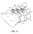
- connection assembly as installed in a spinal column 110 is shown in Fig. 11.
- the bolts 88 are inserted into the vertebrae 114 in the position that is desired by the surgeon.
- the rod 80 is bent so as to align with the bolts 88. It can be seen from Fig. 11 that precise alignment of the rod 80 with the differing heights and relative angles of the bolts 88 is difficult.
- the invention provides flexibility in the connection of the rod 80 to the bolts 88 by permitting relative height adjustment of the rod 80 to the bolts 88, angular adjustment about the X and Y axes (Fig. 10) and linear adjustment about the X, Y and Z axes.
- the set screws 24 are tightened by the surgeon when the desired position is obtained to secure the connection assembly in position.
- a rod connecting member 130 has an aperture 134 adapted to receive the rod 80.
- Suitable fastening structure such as the set screw 138 can be provided in a threaded opening 140 to urge the rod 80 within the aperture 134.
- a bolt connecting member 150 has an aperture 152 adapted to receive the bolt 88.
- the bolt connecting member 150 has an end which terminates in an extension 154 which has an open-ended slot 156.
- a pin 158 that is connected to the rod connecting member 130 has a head 160 which is adapted to fit behind the slot 156 and engage the slotted extension 154 in the manner depicted in Figs. 14-15. This will rotatably engage the rod connecting member 130 to the bolt connecting member 150.
- a rod interface washer 164 and a bolt interface washer 168 are provided.
- the rod interface washer 164 and bolt interface washer 168 include suitable engagement structure such as grooves by which relative rotation of the washers is prevented when the washers are pressed together.
- the rod interface washer 164 does not rotate relative to the rod connecting member 130, and the bolt interface washer 168 does not rotate relative to the bolt connecting member 150. Tightening of the set screw 138 will urge the rod 80 against the rod interface washer 164.
- FIG. 16-18 Yet another embodiment of the invention is shown in Figs. 16-18.
- the rod 80 is positioned through a suitable aperture in rod connecting member 190.
- the bolt 88 is positioned through a suitable aperture or opening in a bolt connecting member 194.
- the rod connecting member 190 and bolt connecting member 194 are rotatably engaged to one another.
- a rod interface washer 198 is provided and does not rotate relative to the rod connecting member 190.
- a bolt interface washer 200 is provided and does not rotate relative to the bolt connecting member 194.
- the rod interface washer 198 and bolt interface washer 200 can have suitable engagement structure such as grooves 64 so that, when pressed together, relative rotation of the rod interface washer 198 with respect to the bolt interface washer 200, and also rotation of the rod connecting member 190 relative to the bolt connecting member 194, is prevented.
- the bolt interface washer 200 has a beveled surface 204.
- a series of radial grooves 208 can be provided on the bolt interface washer 200 to engage the bolt 88.
- a central opening 212 is provided to fit over a portion of the bolt connecting member 194.
- a wedge nut 216 includes a threaded opening for threaded movement on the threads 220 of the bolt 88.
- a wedge surface 224 is provided on a lower depending side of the wedge nut 216.
- the wedge nut 216 is tightened. This will cause the wedge surface 224 of the wedge nut 216 to contact the beveled surface 204 of the bolt interface washer 200. Continued downward movement of the wedge nut 216 will cause the bolt interface washer 200 to press against the rod interface washer 198, which will force the rod 80 into engagement with the rod connecting member 190. The force between the rod interface washer 198 and bolt interface washer 200 will cause engagement of the grooves 64 to secure the rod interface washer 198 from rotation relative to the bolt interface washer 200 so as to fix the relative position of the rod connecting member 190 to the bolt connecting member 194. The bolt 88 will be urged against the bolt connecting member 194.
- the grooves 208 will serve to engage the bolt 88 so as to prevent rotation.
- a protrusion 226 on the bolt 88 is contacted by the bolt interface washer 200 as the wedge nut 216 is urged downward so as to prevent downward slippage of the connection assembly from the desired position.
- the invention is capable of taking other alternative forms. It is not necessary that the rod connecting member and bolt connecting member have an aperture for receiving the rod and/or bolt.
- a partially open channel or other suitable structure can alternatively be used, so long as the rod connecting member is capable of fixing the rod, and that fixation of the rod will occur with contact between the rod and at least one washer.
- a connection assembly in which a rod connecting member 250 is substantially J-shaped.
- the rod 80 fits into the open channel 254 and is secured in place by suitable structure such as set screw 260.
- the bolt 88 similarly fits into an open channel formed by a substantially J-shaped bolt connecting member 264.
- a rod interface washer 270 and bolt interface washer 274 are provided as previously described.
- the rod interface washer and bolt interface washer can be replaced by a single interface washer 320.
- the single interface washer 320 according to this embodiment of the invention is shown in Fig. 20.
- the interface washer includes a large central opening 324 and a plurality of radially directed grooves 328 on each side of the washer. The washer will be in contact with both the rod 80 and bolt 88, with the grooves 328 engaging each, so that an engagement between the rod, washer, and the bolt is created and the rod 80 is fixed in space relative to the bolt 88.
- the bolt 88 that is illustrated in the drawings is a common device that is used to secure a rod to the spine. It will be appreciated by those skilled in the art that the invention has utility with other securing devices such as pins, rods, hooks, cylinders, screws and snaps. These devices are commonly cylindrical, but can also be elliptical, rectangular, and other shapes.
Abstract
Description
Claims (8)
- A connection assembly for connecting a spinal implant rod (80) to a spinal implant bolt (88), the assembly comprising:a rod connecting member (14) having an opening (22) for receiving a portion of the rod;a bolt connecting member (18) having an opening (22) for receiving a portion of the bolt,the rod connecting member (14) and bolt connecting member (18) being rotatably engaged to one another;a rod interface washer (60) is positioned over a portion of the rod connecting member (14); characterised bya bolt interface washer (96) which is positioned over a portion of the bolt connecting member(18), the rod interface washer (60) and bolt interface washer (96) being moveable in part between the rod connecting member and the bolt connecting member, the rod interface washer (60) being fixed against rotation relative to the rod connecting member (14) and the bolt interface washer (96) being fixed against rotation relative to the bolt connecting member; anda structure (24) extendable into the opening of at least one of the rod connecting member (14) and the bolt connecting member (18), so as to urge at least one of the rod (80) and bolt (88) toward the other, whereby the rod interface washer (60) and bolt interface washer (96) will be pressed together between the rod (80) and the bolt (88) preventing rotation of the rod interface washer (60) and rod connecting member (14) relative to the bolt interface washer (96) and bolt connecting member (18), and securing the rod to the bolt.
- The assembly of claim 1, further characterised by the interface washers (60,96)having interengagement structure on a surface thereof such that, when pressed together, the interengagement structure will facilitate the engagement of the washers to one another against rotational movement relative to one another.
- The connection assembly of claim 2, further characterised by the interengagement structure comprising variable angle surfaces.
- The connection assembly of claim 1, 2 or 3, further characterised by each of the rod connecting member (14) and bolt connecting member (18) comprising a washer seat (40, 48) and washer stop (44,52) for permitting sliding movement of the respective interface washer over a portion of the respective aperture, said stop surface preventing removal of the interface washer from the respective connecting member.
- The connection assembly of claim 1, 2, 3 or 4, further characterised by the rod connecting member (14) and bolt connecting member (18) being rotationally engaged by corresponding male protrusion (30) and female cavity portions.
- The connection assembly of claim 1, 2, 3, 4 or 5, further characterised by the interface washers comprising an engagement groove.
- The connection assembly of any of claims 1 to 6, further characterised by a threaded element threadedly connected to said bolt.
- The connection assembly of any of claims 1 to 7, further characterised by a wedge nut (216) screwed onto a spinal implant bolt, wherein, in use, said wedge nut contacts at least one of said interface washers.
Priority Applications (1)
| Application Number | Priority Date | Filing Date | Title |
|---|---|---|---|
| EP04024174A EP1500375B1 (en) | 1995-08-14 | 1996-08-14 | Spinal implant connection assembly |
Applications Claiming Priority (3)
| Application Number | Priority Date | Filing Date | Title |
|---|---|---|---|
| US08/515,289 US5643263A (en) | 1995-08-14 | 1995-08-14 | Spinal implant connection assembly |
| US515289 | 1995-08-14 | ||
| PCT/US1996/013167 WO1997006742A1 (en) | 1995-08-14 | 1996-08-14 | Spinal implant connection assembly |
Related Child Applications (1)
| Application Number | Title | Priority Date | Filing Date |
|---|---|---|---|
| EP04024174A Division EP1500375B1 (en) | 1995-08-14 | 1996-08-14 | Spinal implant connection assembly |
Publications (3)
| Publication Number | Publication Date |
|---|---|
| EP0957798A1 EP0957798A1 (en) | 1999-11-24 |
| EP0957798A4 EP0957798A4 (en) | 2000-04-26 |
| EP0957798B1 true EP0957798B1 (en) | 2004-11-10 |
Family
ID=24050736
Family Applications (2)
| Application Number | Title | Priority Date | Filing Date |
|---|---|---|---|
| EP04024174A Expired - Lifetime EP1500375B1 (en) | 1995-08-14 | 1996-08-14 | Spinal implant connection assembly |
| EP96928858A Expired - Lifetime EP0957798B1 (en) | 1995-08-14 | 1996-08-14 | Spinal implant connection assembly |
Family Applications Before (1)
| Application Number | Title | Priority Date | Filing Date |
|---|---|---|---|
| EP04024174A Expired - Lifetime EP1500375B1 (en) | 1995-08-14 | 1996-08-14 | Spinal implant connection assembly |
Country Status (9)
| Country | Link |
|---|---|
| US (2) | US5643263A (en) |
| EP (2) | EP1500375B1 (en) |
| JP (1) | JP3862030B2 (en) |
| AT (2) | ATE508698T1 (en) |
| AU (1) | AU717852B2 (en) |
| CA (1) | CA2226972C (en) |
| DE (1) | DE69633834T2 (en) |
| ES (1) | ES2239337T3 (en) |
| WO (1) | WO1997006742A1 (en) |
Cited By (1)
| Publication number | Priority date | Publication date | Assignee | Title |
|---|---|---|---|---|
| DE10310005C5 (en) * | 2003-02-27 | 2008-10-30 | Aesculap Ag | Surgical holding device |
Families Citing this family (171)
| Publication number | Priority date | Publication date | Assignee | Title |
|---|---|---|---|---|
| US5947967A (en) * | 1997-10-22 | 1999-09-07 | Sdgt Holdings, Inc. | Variable angle connector |
| AU3187000A (en) * | 1999-03-07 | 2000-09-28 | Discure Ltd. | Method and apparatus for computerized surgery |
| US6283967B1 (en) | 1999-12-17 | 2001-09-04 | Synthes (U.S.A.) | Transconnector for coupling spinal rods |
| US6234705B1 (en) | 1999-04-06 | 2001-05-22 | Synthes (Usa) | Transconnector for coupling spinal rods |
| US6471703B1 (en) * | 1999-04-21 | 2002-10-29 | Sdgi Holdings, Inc. | Variable angle connection assembly for a spinal implant system |
| US6183473B1 (en) | 1999-04-21 | 2001-02-06 | Richard B Ashman | Variable angle connection assembly for a spinal implant system |
| US7674293B2 (en) | 2004-04-22 | 2010-03-09 | Facet Solutions, Inc. | Crossbar spinal prosthesis having a modular design and related implantation methods |
| US8187303B2 (en) | 2004-04-22 | 2012-05-29 | Gmedelaware 2 Llc | Anti-rotation fixation element for spinal prostheses |
| US6974478B2 (en) * | 1999-10-22 | 2005-12-13 | Archus Orthopedics, Inc. | Prostheses, systems and methods for replacement of natural facet joints with artificial facet joint surfaces |
| EP2204144B1 (en) * | 1999-10-22 | 2013-04-03 | Gmedelaware 2 LLC | Facet arthroplasty devices and methods |
| US7691145B2 (en) | 1999-10-22 | 2010-04-06 | Facet Solutions, Inc. | Prostheses, systems and methods for replacement of natural facet joints with artificial facet joint surfaces |
| US6811567B2 (en) * | 1999-10-22 | 2004-11-02 | Archus Orthopedics Inc. | Facet arthroplasty devices and methods |
| US6562038B1 (en) | 2000-03-15 | 2003-05-13 | Sdgi Holdings, Inc. | Spinal implant connection assembly |
| US6309391B1 (en) | 2000-03-15 | 2001-10-30 | Sdgi Holding, Inc. | Multidirectional pivoting bone screw and fixation system |
| US6572618B1 (en) * | 2000-03-15 | 2003-06-03 | Sdgi Holdings, Inc. | Spinal implant connection assembly |
| US6248107B1 (en) | 2000-03-15 | 2001-06-19 | Sdgi Holdings, Inc. | System for reducing the displacement of a vertebra |
| US7322979B2 (en) * | 2000-03-15 | 2008-01-29 | Warsaw Orthopedic, Inc. | Multidirectional pivoting bone screw and fixation system |
| US6872209B2 (en) * | 2000-03-15 | 2005-03-29 | Sdgi Holdings, Inc. | Spinal implant connection assembly |
| WO2002002022A1 (en) | 2000-06-30 | 2002-01-10 | Stephen Ritland | Polyaxial connection device and method |
| US6551318B1 (en) | 2000-07-26 | 2003-04-22 | Stahurski Consulting Inc. | Spinal column retaining apparatus |
| US6620164B2 (en) * | 2000-09-22 | 2003-09-16 | Showa Ika Kohgyo Co., Ltd. | Rod for cervical vertebra and connecting system thereof |
| US6692434B2 (en) | 2000-09-29 | 2004-02-17 | Stephen Ritland | Method and device for retractor for microsurgical intermuscular lumbar arthrodesis |
| US7166073B2 (en) | 2000-09-29 | 2007-01-23 | Stephen Ritland | Method and device for microsurgical intermuscular spinal surgery |
| US20080177310A1 (en) * | 2000-10-20 | 2008-07-24 | Archus Orthopedics, Inc. | Facet arthroplasty devices and methods |
| US6685705B1 (en) | 2000-10-23 | 2004-02-03 | Sdgi Holdings, Inc. | Six-axis and seven-axis adjustable connector |
| US6520962B1 (en) | 2000-10-23 | 2003-02-18 | Sdgi Holdings, Inc. | Taper-locked adjustable connector |
| US6579292B2 (en) | 2001-06-18 | 2003-06-17 | Sdgi Holdings, Inc. | Connection assembly for spinal implant systems |
| JP4249021B2 (en) | 2001-09-28 | 2009-04-02 | リットランド、ステファン | Connecting rod for screw or hook multi-axis system and method of use |
| US6991632B2 (en) | 2001-09-28 | 2006-01-31 | Stephen Ritland | Adjustable rod and connector device and method of use |
| FR2830742B1 (en) * | 2001-10-17 | 2004-07-30 | Spinevision Sa | SYSTEM FOR MAINTAINING AT LEAST TWO VERTEBRAINS IN RELATION TO THE OTHER FOR REALIZING A RACHIDIAN OSTEOSYNTHESIS |
| FR2831420B1 (en) * | 2001-10-30 | 2004-07-16 | Vitatech | APPARATUS FOR HOLDING THE SPIN WITH JOINTING ASSEMBLY |
| US6648887B2 (en) | 2002-01-23 | 2003-11-18 | Richard B. Ashman | Variable angle spinal implant connection assembly |
| CA2473930C (en) * | 2002-01-23 | 2007-10-30 | Richard B. Ashman | Variable angle spinal implant connection assembly |
| AU2004203309B2 (en) * | 2002-01-23 | 2008-12-11 | Richard B. Ashman | Variable Angle Spinal Implant Connection Assembly |
| ATE476930T1 (en) * | 2002-02-20 | 2010-08-15 | Stephen Ritland | DEVICE FOR CONNECTING HAND SCREWS |
| US6966910B2 (en) | 2002-04-05 | 2005-11-22 | Stephen Ritland | Dynamic fixation device and method of use |
| WO2003094699A2 (en) | 2002-05-08 | 2003-11-20 | Stephen Ritland | Dynamic fixation device and method of use |
| AU2003244854A1 (en) * | 2002-07-09 | 2004-01-23 | Anglo-European College Of Chiropractic Ltd | Method for imaging the relative motion of skeletal segments |
| WO2004021901A1 (en) | 2002-09-04 | 2004-03-18 | Aesculap Ag & Co. Kg | Orthopedic fixation device |
| US7887539B2 (en) | 2003-01-24 | 2011-02-15 | Depuy Spine, Inc. | Spinal rod approximators |
| US20070023304A1 (en) * | 2003-02-11 | 2007-02-01 | Joyce James C | Magnetic tool organizing system and method of manufacturing a magnetic tool organizing system |
| US7608104B2 (en) | 2003-05-14 | 2009-10-27 | Archus Orthopedics, Inc. | Prostheses, tools and methods for replacement of natural facet joints with artifical facet joint surfaces |
| US20040230201A1 (en) * | 2003-05-14 | 2004-11-18 | Archus Orthopedics Inc. | Prostheses, tools and methods for replacement of natural facet joints with artifical facet joint surfaces |
| US20040230304A1 (en) * | 2003-05-14 | 2004-11-18 | Archus Orthopedics Inc. | Prostheses, tools and methods for replacement of natural facet joints with artifical facet joint surfaces |
| US8262571B2 (en) | 2003-05-22 | 2012-09-11 | Stephen Ritland | Intermuscular guide for retractor insertion and method of use |
| US7270665B2 (en) * | 2003-06-11 | 2007-09-18 | Sdgi Holdings, Inc. | Variable offset spinal fixation system |
| US7074238B2 (en) | 2003-07-08 | 2006-07-11 | Archus Orthopedics, Inc. | Prostheses, tools and methods for replacement of natural facet joints with artificial facet joint surfaces |
| FR2860138A1 (en) * | 2003-09-26 | 2005-04-01 | Stryker Spine | ASSEMBLY AND METHOD OF FIXING BONES |
| US7083622B2 (en) * | 2003-11-10 | 2006-08-01 | Simonson Peter M | Artificial facet joint and method |
| US20050101953A1 (en) * | 2003-11-10 | 2005-05-12 | Simonson Peter M. | Artificial facet joint and method |
| US7261715B2 (en) * | 2003-11-24 | 2007-08-28 | Sdgi Holdings, Inc. | Grommet assembly |
| US8097023B2 (en) * | 2003-11-24 | 2012-01-17 | Warsaw Orthopedic, Inc. | Grommet assembly |
| US20050131406A1 (en) | 2003-12-15 | 2005-06-16 | Archus Orthopedics, Inc. | Polyaxial adjustment of facet joint prostheses |
| US8236028B2 (en) * | 2004-03-31 | 2012-08-07 | Depuy Spine Sarl | Spinal rod connector |
| US7909852B2 (en) | 2004-03-31 | 2011-03-22 | Depuy Spine Sarl | Adjustable-angle spinal fixation element |
| US20050228382A1 (en) * | 2004-04-12 | 2005-10-13 | Marc Richelsoph | Screw and rod fixation assembly and device |
| US7377922B2 (en) * | 2004-04-15 | 2008-05-27 | Warsaw Orthopedic, Inc. | Transfer ring for offset tapered 3D connector |
| US7051451B2 (en) | 2004-04-22 | 2006-05-30 | Archus Orthopedics, Inc. | Facet joint prosthesis measurement and implant tools |
| US7914556B2 (en) | 2005-03-02 | 2011-03-29 | Gmedelaware 2 Llc | Arthroplasty revision system and method |
| US20080082171A1 (en) * | 2004-04-22 | 2008-04-03 | Kuiper Mark K | Crossbar spinal prosthesis having a modular design and systems for treating spinal pathologies |
| US7406775B2 (en) * | 2004-04-22 | 2008-08-05 | Archus Orthopedics, Inc. | Implantable orthopedic device component selection instrument and methods |
| US20070093833A1 (en) * | 2004-05-03 | 2007-04-26 | Kuiper Mark K | Crossbar spinal prosthesis having a modular design and related implantation methods |
| US7744635B2 (en) * | 2004-06-09 | 2010-06-29 | Spinal Generations, Llc | Spinal fixation system |
| US7938848B2 (en) | 2004-06-09 | 2011-05-10 | Life Spine, Inc. | Spinal fixation system |
| US8021398B2 (en) * | 2004-06-09 | 2011-09-20 | Life Spine, Inc. | Spinal fixation system |
| US7744634B2 (en) * | 2004-06-15 | 2010-06-29 | Warsaw Orthopedic, Inc. | Spinal rod system |
| US8114158B2 (en) | 2004-08-03 | 2012-02-14 | Kspine, Inc. | Facet device and method |
| AU2005277363A1 (en) | 2004-08-18 | 2006-03-02 | Fsi Acquisition Sub, Llc | Adjacent level facet arthroplasty devices, spine stabilization systems, and methods |
| US20060041311A1 (en) * | 2004-08-18 | 2006-02-23 | Mcleer Thomas J | Devices and methods for treating facet joints |
| US7455639B2 (en) | 2004-09-20 | 2008-11-25 | Stephen Ritland | Opposing parallel bladed retractor and method of use |
| US20060079895A1 (en) * | 2004-09-30 | 2006-04-13 | Mcleer Thomas J | Methods and devices for improved bonding of devices to bone |
| US20060085075A1 (en) * | 2004-10-04 | 2006-04-20 | Archus Orthopedics, Inc. | Polymeric joint complex and methods of use |
| US7572280B2 (en) * | 2004-10-05 | 2009-08-11 | Warsaw Orthopedic, Inc. | Multi-axial anchor assemblies for spinal implants and methods |
| US7794477B2 (en) * | 2004-10-05 | 2010-09-14 | Warsaw Orthopedic, Inc. | Spinal implants and methods with extended multi-axial anchor assemblies |
| US7722654B2 (en) * | 2004-10-05 | 2010-05-25 | Warsaw Orthopedic, Inc. | Spinal implants with multi-axial anchor assembly and methods |
| CA2585135A1 (en) | 2004-10-25 | 2006-05-26 | Archus Orthopedics, Inc. | Spinal prosthesis having a modular design |
| US7896905B2 (en) * | 2005-02-09 | 2011-03-01 | David Lee | Bone fixation apparatus |
| US7951172B2 (en) | 2005-03-04 | 2011-05-31 | Depuy Spine Sarl | Constrained motion bone screw assembly |
| US7951175B2 (en) * | 2005-03-04 | 2011-05-31 | Depuy Spine, Inc. | Instruments and methods for manipulating a vertebra |
| US8496686B2 (en) | 2005-03-22 | 2013-07-30 | Gmedelaware 2 Llc | Minimally invasive spine restoration systems, devices, methods and kits |
| US7338491B2 (en) * | 2005-03-22 | 2008-03-04 | Spinefrontier Inc | Spinal fixation locking mechanism |
| EP1865891B1 (en) * | 2005-03-22 | 2017-05-03 | Gmedelaware 2 LLC | Minimally invasive spine restoration devices |
| US7794481B2 (en) * | 2005-04-22 | 2010-09-14 | Warsaw Orthopedic, Inc. | Force limiting coupling assemblies for spinal implants |
| US7850715B2 (en) * | 2005-04-29 | 2010-12-14 | Warsaw Orthopedic Inc. | Orthopedic implant apparatus |
| US7695499B2 (en) * | 2005-04-29 | 2010-04-13 | Warsaw Orthopedic, Inc. | System, devices and method for augmenting existing fusion constructs |
| US8128665B2 (en) * | 2005-04-29 | 2012-03-06 | Warsaw Orthopedic, Inc. | Orthopedic implant apparatus |
| US7811310B2 (en) * | 2005-05-04 | 2010-10-12 | Spinefrontier, Inc | Multistage spinal fixation locking mechanism |
| JP4613867B2 (en) * | 2005-05-26 | 2011-01-19 | ソニー株式会社 | Content processing apparatus, content processing method, and computer program |
| EP1906885B2 (en) | 2005-07-19 | 2019-01-16 | Warsaw Orthopedic, Inc. | Rod extension for extending fusion construct |
| US7625394B2 (en) * | 2005-08-05 | 2009-12-01 | Warsaw Orthopedic, Inc. | Coupling assemblies for spinal implants |
| US8262702B2 (en) * | 2005-08-23 | 2012-09-11 | Synthes Usa, Llc | Osteosynthetic clamp for attaching a bone anchor to a support rod |
| US7722651B2 (en) * | 2005-10-21 | 2010-05-25 | Depuy Spine, Inc. | Adjustable bone screw assembly |
| GB0521582D0 (en) | 2005-10-22 | 2005-11-30 | Depuy Int Ltd | An implant for supporting a spinal column |
| US7517359B2 (en) | 2005-12-20 | 2009-04-14 | Sdgi Holdings, Inc. | Vertebral rod assemblies and methods |
| US7575587B2 (en) * | 2005-12-30 | 2009-08-18 | Warsaw Orthopedic, Inc. | Top-tightening side-locking spinal connector assembly |
| US8663287B2 (en) * | 2006-01-10 | 2014-03-04 | Life Spine, Inc. | Pedicle screw constructs and spinal rod attachment assemblies |
| GB0600662D0 (en) | 2006-01-13 | 2006-02-22 | Depuy Int Ltd | Spinal support rod kit |
| US20070173825A1 (en) * | 2006-01-20 | 2007-07-26 | Stryker Spine | Spinal rod parallel coupler |
| US20070173827A1 (en) * | 2006-01-20 | 2007-07-26 | Sdgi Holdings, Inc. | Adjustable connector for attachment to a rod in a medical application |
| US8348952B2 (en) | 2006-01-26 | 2013-01-08 | Depuy International Ltd. | System and method for cooling a spinal correction device comprising a shape memory material for corrective spinal surgery |
| US8075604B2 (en) | 2006-02-16 | 2011-12-13 | Warsaw Orthopedic, Inc. | Multi-thread bone screw and method |
| US7585299B2 (en) * | 2006-02-17 | 2009-09-08 | Warsaw Orthopedic, Inc. | Dorsal adjusting spinal connector assembly |
| US7850716B2 (en) * | 2006-02-17 | 2010-12-14 | Warsaw Orthopedic, Inc. | Adjustable interconnection device |
| US7850717B2 (en) * | 2006-03-01 | 2010-12-14 | Warsaw Orthopedic, Inc. | Bone anchors having two or more portions exhibiting different performance characteristics and method of forming the same |
| US20070233256A1 (en) * | 2006-03-15 | 2007-10-04 | Ohrt John A | Facet and disc arthroplasty system and method |
| US7753940B2 (en) * | 2006-04-05 | 2010-07-13 | Warsaw Orthopedic, Inc. | Lateral connector assembly |
| CA2648204C (en) | 2006-04-11 | 2014-07-22 | Synthes (U.S.A.) | Minimally invasive fixation system |
| US8676293B2 (en) * | 2006-04-13 | 2014-03-18 | Aecc Enterprises Ltd. | Devices, systems and methods for measuring and evaluating the motion and function of joint structures and associated muscles, determining suitability for orthopedic intervention, and evaluating efficacy of orthopedic intervention |
| US20070270815A1 (en) * | 2006-04-20 | 2007-11-22 | Chris Johnson | Bone anchors with end-loading receivers for elongated connecting elements in spinal surgical procedures |
| US7959564B2 (en) | 2006-07-08 | 2011-06-14 | Stephen Ritland | Pedicle seeker and retractor, and methods of use |
| EP2046216B1 (en) * | 2006-07-27 | 2011-05-18 | Synthes GmbH | Outrigger |
| US8702755B2 (en) | 2006-08-11 | 2014-04-22 | Gmedelaware 2 Llc | Angled washer polyaxial connection for dynamic spine prosthesis |
| US7942906B2 (en) * | 2007-02-12 | 2011-05-17 | Neurospine Innovations And Solutions, Llc | Spinal stabilization system for the stabilization and fixation of the lumbar spine and method for using same |
| US8128671B2 (en) * | 2007-04-04 | 2012-03-06 | Warsaw Orthopedic, Inc. | Variable flank bone screw |
| US20080281362A1 (en) * | 2007-05-09 | 2008-11-13 | Jeremy Lemoine | Device and system for cranial support |
| WO2009011929A1 (en) * | 2007-07-19 | 2009-01-22 | Synthes (U.S.A.) | Clamps used for interconnecting a bone anchor to a rod |
| US20090076549A1 (en) * | 2007-09-17 | 2009-03-19 | Warsaw Orthopedic, Inc. | Orthopedic implant system |
| US8147519B2 (en) * | 2007-10-09 | 2012-04-03 | Warsaw Orthopedic, Inc. | Variable angle rod connectors and the methods of use |
| US20090099481A1 (en) | 2007-10-10 | 2009-04-16 | Adam Deitz | Devices, Systems and Methods for Measuring and Evaluating the Motion and Function of Joints and Associated Muscles |
| GB0720762D0 (en) * | 2007-10-24 | 2007-12-05 | Depuy Spine Sorl | Assembly for orthopaedic surgery |
| WO2009092080A2 (en) * | 2008-01-18 | 2009-07-23 | Lee David M D | Bone fixation apparatus |
| US8709015B2 (en) | 2008-03-10 | 2014-04-29 | DePuy Synthes Products, LLC | Bilateral vertebral body derotation system |
| US8608746B2 (en) | 2008-03-10 | 2013-12-17 | DePuy Synthes Products, LLC | Derotation instrument with reduction functionality |
| WO2009145757A1 (en) * | 2008-05-27 | 2009-12-03 | Warsaw Orthopedic, Inc. | Connecting device for orthopedic surgery |
| US10973556B2 (en) * | 2008-06-17 | 2021-04-13 | DePuy Synthes Products, Inc. | Adjustable implant assembly |
| US20100049253A1 (en) * | 2008-08-20 | 2010-02-25 | Warsaw Orthopedic, Inc. | Bottom loading connector for attaching a spinal rod to a vertebral member |
| US8147523B2 (en) * | 2008-09-09 | 2012-04-03 | Warsaw Orthopedic, Inc. | Offset vertebral rod connector |
| EP2387366B1 (en) * | 2008-10-24 | 2018-05-09 | Globus Medical, Inc. | Variable angle connection assembly |
| US8066746B2 (en) | 2008-12-23 | 2011-11-29 | Globus Medical, Inc. | Variable angle connection assembly |
| US8828058B2 (en) | 2008-11-11 | 2014-09-09 | Kspine, Inc. | Growth directed vertebral fixation system with distractible connector(s) and apical control |
| US8252030B2 (en) * | 2009-03-10 | 2012-08-28 | Globus Medical, Inc. | Spinal implant connection assembly |
| US8357182B2 (en) | 2009-03-26 | 2013-01-22 | Kspine, Inc. | Alignment system with longitudinal support features |
| EP2432407B1 (en) | 2009-05-20 | 2013-04-17 | Synthes GmbH | Patient-mounted retractor |
| US20100318129A1 (en) * | 2009-06-16 | 2010-12-16 | Kspine, Inc. | Deformity alignment system with reactive force balancing |
| US9168071B2 (en) | 2009-09-15 | 2015-10-27 | K2M, Inc. | Growth modulation system |
| WO2011038236A2 (en) | 2009-09-25 | 2011-03-31 | Ortho Kinematics, Inc. | Systems and devices for an integrated imaging system with real-time feedback loops and methods therefor |
| US20110106181A1 (en) * | 2009-10-30 | 2011-05-05 | Warsaw Orthopedic, Inc. | Adjustable saddle for a bone anchor |
| US8070781B2 (en) | 2010-01-12 | 2011-12-06 | Globus Medical, Inc. | Offset variable angle connection assembly |
| US8317837B2 (en) * | 2010-02-05 | 2012-11-27 | Warsaw Orthopedic, Inc. | Connector and method |
| US8617216B2 (en) * | 2010-04-05 | 2013-12-31 | David L. Brumfield | Fully-adjustable bone fixation device |
| US8535318B2 (en) | 2010-04-23 | 2013-09-17 | DePuy Synthes Products, LLC | Minimally invasive instrument set, devices and related methods |
| EP3649937A1 (en) | 2010-12-13 | 2020-05-13 | Statera Spine, Inc. | Methods, systems and devices for clinical data reporting and surgical navigation |
| US9387013B1 (en) | 2011-03-01 | 2016-07-12 | Nuvasive, Inc. | Posterior cervical fixation system |
| US9314274B2 (en) | 2011-05-27 | 2016-04-19 | DePuy Synthes Products, Inc. | Minimally invasive spinal fixation system including vertebral alignment features |
| JP6158176B2 (en) | 2011-06-03 | 2017-07-05 | ケイツーエム インコーポレイテッドK2M,Inc. | Spine correction system |
| US9005249B2 (en) | 2011-07-11 | 2015-04-14 | Life Spine, Inc. | Spinal rod connector assembly |
| US20130085534A1 (en) * | 2011-09-30 | 2013-04-04 | Nicolas Hainard | Connectors for a secondary bone anchor |
| US8940032B2 (en) | 2011-10-26 | 2015-01-27 | Globus Medical, Inc. | Connection assembly |
| WO2014172632A2 (en) | 2011-11-16 | 2014-10-23 | Kspine, Inc. | Spinal correction and secondary stabilization |
| US9451987B2 (en) | 2011-11-16 | 2016-09-27 | K2M, Inc. | System and method for spinal correction |
| US9468468B2 (en) | 2011-11-16 | 2016-10-18 | K2M, Inc. | Transverse connector for spinal stabilization system |
| US9468469B2 (en) | 2011-11-16 | 2016-10-18 | K2M, Inc. | Transverse coupler adjuster spinal correction systems and methods |
| US8920472B2 (en) | 2011-11-16 | 2014-12-30 | Kspine, Inc. | Spinal correction and secondary stabilization |
| US9017386B2 (en) | 2013-03-08 | 2015-04-28 | Warsaw Orthopedic, Inc. | Iliac connectors |
| US9468471B2 (en) | 2013-09-17 | 2016-10-18 | K2M, Inc. | Transverse coupler adjuster spinal correction systems and methods |
| US20160354161A1 (en) | 2015-06-05 | 2016-12-08 | Ortho Kinematics, Inc. | Methods for data processing for intra-operative navigation systems |
| US11446063B2 (en) | 2016-02-12 | 2022-09-20 | Nuvasive, Inc. | Post-operatively adjustable angled rod |
| WO2017139782A1 (en) | 2016-02-12 | 2017-08-17 | Nuvasive, Inc. | Post-operatively adjustable angled rod |
| US10004538B2 (en) * | 2016-04-27 | 2018-06-26 | Warsaw Orthopedic, Inc. | Surgical instrument and method |
| US10441324B2 (en) | 2016-08-17 | 2019-10-15 | Warsaw Orthopedic, Inc. | Spinal construct and method |
| US10172719B2 (en) | 2017-02-14 | 2019-01-08 | Warsaw Orthopedic, Inc. | Surgical system and method of use |
| US20180228516A1 (en) | 2017-02-14 | 2018-08-16 | Warsaw Orthopedic, Inc. | Spinal implant system and method |
| US10653455B2 (en) | 2017-09-12 | 2020-05-19 | Warsaw Orthopedic, Inc. | Spinal implant system and methods of use |
| CA3083204A1 (en) | 2017-11-27 | 2019-05-31 | Rafic Saleh | Endoscopic snare |
| US10687862B2 (en) | 2018-03-29 | 2020-06-23 | Warsaw Orthopedic, Inc. | Spinal implant connector and methods |
| US11311317B2 (en) | 2019-09-25 | 2022-04-26 | Stelios KOUTSOUMBELIS | Spinal fixation device with rotatable connector |
| US11291477B1 (en) | 2021-05-04 | 2022-04-05 | Warsaw Orthopedic, Inc. | Dorsal adjusting implant and methods of use |
| US11432848B1 (en) | 2021-05-12 | 2022-09-06 | Warsaw Orthopedic, Inc. | Top loading quick lock construct |
| US11712270B2 (en) | 2021-05-17 | 2023-08-01 | Warsaw Orthopedic, Inc. | Quick lock clamp constructs and associated methods |
| US11957391B2 (en) | 2021-11-01 | 2024-04-16 | Warsaw Orthopedic, Inc. | Bone screw having an overmold of a shank |
| US11849979B1 (en) * | 2022-05-16 | 2023-12-26 | Warsaw Orthopedic, Inc. | Spinal implant system and method |
Family Cites Families (25)
| Publication number | Priority date | Publication date | Assignee | Title |
|---|---|---|---|---|
| US3317225A (en) * | 1965-04-23 | 1967-05-02 | William T Cooper | Sun-visor attachment |
| US4611582A (en) * | 1983-12-27 | 1986-09-16 | Wisconsin Alumni Research Foundation | Vertebral clamp |
| US4614452A (en) * | 1984-02-28 | 1986-09-30 | Wang Cheng H | Angle adjusting device |
| SE458417B (en) * | 1985-08-15 | 1989-04-03 | Sven Olerud | FIXING INSTRUMENTS PROVIDED FOR USE IN SPINE OPERATIONS |
| US4738252A (en) * | 1987-09-18 | 1988-04-19 | Friddle's Orthopedic Appliances, Inc. | Mechanical joint construction |
| CH683963A5 (en) * | 1988-06-10 | 1994-06-30 | Synthes Ag | Internal fixation. |
| DE3823737A1 (en) * | 1988-07-13 | 1990-01-18 | Lutz Biedermann | CORRECTION AND HOLDING DEVICE, ESPECIALLY FOR THE SPINE |
| FR2651992B1 (en) * | 1989-09-18 | 1991-12-13 | Sofamor | IMPLANT FOR ANTERIOR DORSO-LUMBAR SPINE OSTEOSYNTHESIS FOR CORRECTION OF CYPHOSIS. |
| SE8903403D0 (en) * | 1989-10-16 | 1989-10-16 | Sven Olerud | DEVICE FOR FIXING INSTRUMENTS FOR BACKGROUND OPERATIONS |
| US5002542A (en) * | 1989-10-30 | 1991-03-26 | Synthes U.S.A. | Pedicle screw clamp |
| US5344422A (en) * | 1989-10-30 | 1994-09-06 | Synthes (U.S.A.) | Pedicular screw clamp |
| US5013085A (en) * | 1989-11-20 | 1991-05-07 | Craig John R | Lounge chair canopy construction |
| IT1236172B (en) * | 1989-11-30 | 1993-01-11 | Franco Mingozzi | EXTERNAL FIXER FOR THE TREATMENT OF LONG BONE FRACTURES OF THE LIMBS. |
| US5108397A (en) * | 1990-04-19 | 1992-04-28 | Joseph White | Method and apparatus for stabilization of pelvic fractures |
| US5129900B1 (en) * | 1990-07-24 | 1998-12-29 | Acromed Corp | Spinal column retaining method and apparatus |
| SE9002569D0 (en) * | 1990-08-03 | 1990-08-03 | Sven Olerud | SPINAL KNUT |
| DE9108566U1 (en) * | 1991-07-12 | 1991-10-10 | Pennig, Dietmar, Dr.Med., 4400 Muenster, De | |
| DE4123439C1 (en) * | 1991-07-16 | 1992-11-12 | Dietmar Dr.Med. Priv. Doz. 4400 Muenster De Pennig | |
| US5254118A (en) * | 1991-12-04 | 1993-10-19 | Srdjian Mirkovic | Three dimensional spine fixation system |
| US5190390A (en) * | 1992-01-08 | 1993-03-02 | Ming Tai Huang | Joint for connecting a canopy support to a stroller |
| US5261909A (en) * | 1992-02-18 | 1993-11-16 | Danek Medical, Inc. | Variable angle screw for spinal implant system |
| DE4231443C1 (en) * | 1992-09-19 | 1993-10-14 | Pennig Dietmar | Osteosynthesis tools |
| US5423818A (en) * | 1993-02-17 | 1995-06-13 | Danek Medical, Inc. | Clamp for attaching a vertebral fixation element to a spinal rod |
| DE4307576C1 (en) * | 1993-03-10 | 1994-04-21 | Biedermann Motech Gmbh | Bone screw esp. for spinal column correction - has U=shaped holder section for receiving straight or bent rod |
| US5443515A (en) * | 1994-01-26 | 1995-08-22 | Implex Corporation | Vertebral body prosthetic implant with slidably positionable stabilizing member |
-
1995
- 1995-08-14 US US08/515,289 patent/US5643263A/en not_active Expired - Lifetime
-
1996
- 1996-08-14 AT AT04024174T patent/ATE508698T1/en not_active IP Right Cessation
- 1996-08-14 DE DE69633834T patent/DE69633834T2/en not_active Expired - Lifetime
- 1996-08-14 ES ES96928858T patent/ES2239337T3/en not_active Expired - Lifetime
- 1996-08-14 CA CA002226972A patent/CA2226972C/en not_active Expired - Fee Related
- 1996-08-14 JP JP50944797A patent/JP3862030B2/en not_active Expired - Lifetime
- 1996-08-14 WO PCT/US1996/013167 patent/WO1997006742A1/en active IP Right Grant
- 1996-08-14 AT AT96928858T patent/ATE281789T1/en not_active IP Right Cessation
- 1996-08-14 AU AU68459/96A patent/AU717852B2/en not_active Expired
- 1996-08-14 EP EP04024174A patent/EP1500375B1/en not_active Expired - Lifetime
- 1996-08-14 EP EP96928858A patent/EP0957798B1/en not_active Expired - Lifetime
- 1996-12-16 US US08/775,705 patent/US5885285A/en not_active Expired - Lifetime
Cited By (1)
| Publication number | Priority date | Publication date | Assignee | Title |
|---|---|---|---|---|
| DE10310005C5 (en) * | 2003-02-27 | 2008-10-30 | Aesculap Ag | Surgical holding device |
Also Published As
| Publication number | Publication date |
|---|---|
| DE69633834D1 (en) | 2004-12-16 |
| CA2226972A1 (en) | 1997-02-27 |
| AU717852B2 (en) | 2000-04-06 |
| JP2001515367A (en) | 2001-09-18 |
| CA2226972C (en) | 2007-09-11 |
| JP3862030B2 (en) | 2006-12-27 |
| EP0957798A4 (en) | 2000-04-26 |
| AU6845996A (en) | 1997-03-12 |
| WO1997006742A1 (en) | 1997-02-27 |
| US5643263A (en) | 1997-07-01 |
| US5885285A (en) | 1999-03-23 |
| EP1500375A3 (en) | 2005-03-09 |
| DE69633834T2 (en) | 2006-02-02 |
| EP1500375A2 (en) | 2005-01-26 |
| EP0957798A1 (en) | 1999-11-24 |
| ES2239337T3 (en) | 2005-09-16 |
| EP1500375B1 (en) | 2011-05-11 |
| ATE508698T1 (en) | 2011-05-15 |
| ATE281789T1 (en) | 2004-11-15 |
Similar Documents
| Publication | Publication Date | Title |
|---|---|---|
| EP0957798B1 (en) | Spinal implant connection assembly | |
| JP4732453B2 (en) | Orthopedic fixation system | |
| JP4007458B2 (en) | Osteosynthesis system for spinal joint fixation | |
| EP1853179B1 (en) | Bone fastener assembly for bone retention apparatus | |
| US7322979B2 (en) | Multidirectional pivoting bone screw and fixation system | |
| US6309391B1 (en) | Multidirectional pivoting bone screw and fixation system | |
| US10617450B2 (en) | Jointed rod | |
| US6520990B1 (en) | Lateral fixation plates for a spinal system | |
| US5611800A (en) | Spinal fixation system | |
| US5127912A (en) | Sacral implant system | |
| US5810817A (en) | Spinal therapy apparatus | |
| EP1759647B1 (en) | Spinal rod/plate locking mechanism | |
| EP1192910B1 (en) | Rod for cervical vertebra and connecting system thereof | |
| CA2129011A1 (en) | Sacral implant system | |
| AU2001241671A1 (en) | Multidirectional pivoting bone screw and fixation system | |
| WO2002038063A9 (en) | Variable angle connection assembly for a spinal implant system | |
| WO2001067972A2 (en) | Spinal implant connection assembly | |
| AU2001238314A1 (en) | Spinal implant connection assembly | |
| WO2006004367A1 (en) | Pedicle screw assembly and transconnector for coupling rods therein |
Legal Events
| Date | Code | Title | Description |
|---|---|---|---|
| PUAI | Public reference made under article 153(3) epc to a published international application that has entered the european phase |
Free format text: ORIGINAL CODE: 0009012 |
|
| 17P | Request for examination filed |
Effective date: 19980310 |
|
| AK | Designated contracting states |
Kind code of ref document: A1 Designated state(s): AT BE CH DE DK ES FI FR GB GR IE IT LI LU MC NL PT SE |
|
| A4 | Supplementary search report drawn up and despatched |
Effective date: 20000310 |
|
| AK | Designated contracting states |
Kind code of ref document: A4 Designated state(s): AT BE CH DE DK ES FI FR GB GR IE IT LI LU MC NL PT SE |
|
| RIC1 | Information provided on ipc code assigned before grant |
Free format text: 7A 61B 17/56 A, 7A 61B 17/70 B |
|
| 17Q | First examination report despatched |
Effective date: 20020827 |
|
| GRAP | Despatch of communication of intention to grant a patent |
Free format text: ORIGINAL CODE: EPIDOSNIGR1 |
|
| GRAS | Grant fee paid |
Free format text: ORIGINAL CODE: EPIDOSNIGR3 |
|
| GRAA | (expected) grant |
Free format text: ORIGINAL CODE: 0009210 |
|
| AK | Designated contracting states |
Kind code of ref document: B1 Designated state(s): AT BE CH DE DK ES FI FR GB GR IE IT LI LU MC NL PT SE |
|
| PG25 | Lapsed in a contracting state [announced via postgrant information from national office to epo] |
Ref country code: NL Free format text: LAPSE BECAUSE OF FAILURE TO SUBMIT A TRANSLATION OF THE DESCRIPTION OR TO PAY THE FEE WITHIN THE PRESCRIBED TIME-LIMIT Effective date: 20041110 Ref country code: IT Free format text: LAPSE BECAUSE OF FAILURE TO SUBMIT A TRANSLATION OF THE DESCRIPTION OR TO PAY THE FEE WITHIN THE PRESCRIBED TIME-LIMIT;WARNING: LAPSES OF ITALIAN PATENTS WITH EFFECTIVE DATE BEFORE 2007 MAY HAVE OCCURRED AT ANY TIME BEFORE 2007. THE CORRECT EFFECTIVE DATE MAY BE DIFFERENT FROM THE ONE RECORDED. Effective date: 20041110 Ref country code: FI Free format text: LAPSE BECAUSE OF FAILURE TO SUBMIT A TRANSLATION OF THE DESCRIPTION OR TO PAY THE FEE WITHIN THE PRESCRIBED TIME-LIMIT Effective date: 20041110 |
|
| REG | Reference to a national code |
Ref country code: GB Ref legal event code: FG4D |
|
| REG | Reference to a national code |
Ref country code: CH Ref legal event code: EP |
|
| REG | Reference to a national code |
Ref country code: IE Ref legal event code: FG4D |
|
| REF | Corresponds to: |
Ref document number: 69633834 Country of ref document: DE Date of ref document: 20041216 Kind code of ref document: P |
|
| PG25 | Lapsed in a contracting state [announced via postgrant information from national office to epo] |
Ref country code: SE Free format text: LAPSE BECAUSE OF FAILURE TO SUBMIT A TRANSLATION OF THE DESCRIPTION OR TO PAY THE FEE WITHIN THE PRESCRIBED TIME-LIMIT Effective date: 20050210 Ref country code: GR Free format text: LAPSE BECAUSE OF FAILURE TO SUBMIT A TRANSLATION OF THE DESCRIPTION OR TO PAY THE FEE WITHIN THE PRESCRIBED TIME-LIMIT Effective date: 20050210 Ref country code: DK Free format text: LAPSE BECAUSE OF FAILURE TO SUBMIT A TRANSLATION OF THE DESCRIPTION OR TO PAY THE FEE WITHIN THE PRESCRIBED TIME-LIMIT Effective date: 20050210 |
|
| NLV1 | Nl: lapsed or annulled due to failure to fulfill the requirements of art. 29p and 29m of the patents act | ||
| PG25 | Lapsed in a contracting state [announced via postgrant information from national office to epo] |
Ref country code: LU Free format text: LAPSE BECAUSE OF NON-PAYMENT OF DUE FEES Effective date: 20050814 |
|
| PG25 | Lapsed in a contracting state [announced via postgrant information from national office to epo] |
Ref country code: IE Free format text: LAPSE BECAUSE OF NON-PAYMENT OF DUE FEES Effective date: 20050815 |
|
| PG25 | Lapsed in a contracting state [announced via postgrant information from national office to epo] |
Ref country code: MC Free format text: LAPSE BECAUSE OF NON-PAYMENT OF DUE FEES Effective date: 20050831 |
|
| REG | Reference to a national code |
Ref country code: GB Ref legal event code: 732E |
|
| PLBE | No opposition filed within time limit |
Free format text: ORIGINAL CODE: 0009261 |
|
| REG | Reference to a national code |
Ref country code: ES Ref legal event code: FG2A Ref document number: 2239337 Country of ref document: ES Kind code of ref document: T3 |
|
| STAA | Information on the status of an ep patent application or granted ep patent |
Free format text: STATUS: NO OPPOSITION FILED WITHIN TIME LIMIT |
|
| RAP2 | Party data changed (patent owner data changed or rights of a patent transferred) |
Owner name: MEDTRONIC SOFAMOR DANEK, INC. |
|
| RIN2 | Information on inventor provided after grant (corrected) |
Inventor name: THE INVENTOR HAS AGREED TO WAIVE HIS ENTITLEMENT T |
|
| REG | Reference to a national code |
Ref country code: CH Ref legal event code: PUE Owner name: MEDTRONIC SOFAMOR DANEK, INC. Free format text: SIMONSON, PETER MELOTT#SUITE 414, 770 CLAUGHTON ISLAND DRIVE#MIAMI, FL 33131 (US) -TRANSFER TO- MEDTRONIC SOFAMOR DANEK, INC.#1800 PYRAMID PLACE#MEMPHIS, TN 38132 (US) Ref country code: CH Ref legal event code: NV Representative=s name: BOVARD AG PATENTANWAELTE |
|
| 26N | No opposition filed |
Effective date: 20050811 |
|
| ET | Fr: translation filed | ||
| REG | Reference to a national code |
Ref country code: IE Ref legal event code: MM4A |
|
| REG | Reference to a national code |
Ref country code: GB Ref legal event code: 732E |
|
| PG25 | Lapsed in a contracting state [announced via postgrant information from national office to epo] |
Ref country code: PT Free format text: LAPSE BECAUSE OF NON-PAYMENT OF DUE FEES Effective date: 20050410 |
|
| REG | Reference to a national code |
Ref country code: FR Ref legal event code: TP |
|
| PGFP | Annual fee paid to national office [announced via postgrant information from national office to epo] |
Ref country code: ES Payment date: 20080806 Year of fee payment: 13 |
|
| PGFP | Annual fee paid to national office [announced via postgrant information from national office to epo] |
Ref country code: AT Payment date: 20080708 Year of fee payment: 13 |
|
| PGFP | Annual fee paid to national office [announced via postgrant information from national office to epo] |
Ref country code: BE Payment date: 20080828 Year of fee payment: 13 |
|
| BERE | Be: lapsed |
Owner name: *MEDTRONIC SOFAMOR DANEK INC. Effective date: 20090831 |
|
| PG25 | Lapsed in a contracting state [announced via postgrant information from national office to epo] |
Ref country code: BE Free format text: LAPSE BECAUSE OF NON-PAYMENT OF DUE FEES Effective date: 20090831 Ref country code: AT Free format text: LAPSE BECAUSE OF NON-PAYMENT OF DUE FEES Effective date: 20090814 |
|
| REG | Reference to a national code |
Ref country code: ES Ref legal event code: FD2A Effective date: 20090817 |
|
| REG | Reference to a national code |
Ref country code: CH Ref legal event code: PFA Owner name: MEDTRONIC SOFAMOR DANEK, INC. Free format text: MEDTRONIC SOFAMOR DANEK, INC.#1800 PYRAMID PLACE#MEMPHIS, TN 38132 (US) -TRANSFER TO- MEDTRONIC SOFAMOR DANEK, INC.#1800 PYRAMID PLACE#MEMPHIS, TN 38132 (US) |
|
| PG25 | Lapsed in a contracting state [announced via postgrant information from national office to epo] |
Ref country code: ES Free format text: LAPSE BECAUSE OF NON-PAYMENT OF DUE FEES Effective date: 20090815 |
|
| REG | Reference to a national code |
Ref country code: FR Ref legal event code: PLFP Year of fee payment: 20 |
|
| PGFP | Annual fee paid to national office [announced via postgrant information from national office to epo] |
Ref country code: CH Payment date: 20150827 Year of fee payment: 20 Ref country code: DE Payment date: 20150827 Year of fee payment: 20 Ref country code: GB Payment date: 20150827 Year of fee payment: 20 |
|
| PGFP | Annual fee paid to national office [announced via postgrant information from national office to epo] |
Ref country code: FR Payment date: 20150817 Year of fee payment: 20 |
|
| REG | Reference to a national code |
Ref country code: DE Ref legal event code: R071 Ref document number: 69633834 Country of ref document: DE |
|
| REG | Reference to a national code |
Ref country code: CH Ref legal event code: PL |
|
| REG | Reference to a national code |
Ref country code: GB Ref legal event code: PE20 Expiry date: 20160813 |
|
| PG25 | Lapsed in a contracting state [announced via postgrant information from national office to epo] |
Ref country code: GB Free format text: LAPSE BECAUSE OF EXPIRATION OF PROTECTION Effective date: 20160813 |