EP0957823B1 - Aneurysm patch apparatus - Google Patents
Aneurysm patch apparatus Download PDFInfo
- Publication number
- EP0957823B1 EP0957823B1 EP97946316A EP97946316A EP0957823B1 EP 0957823 B1 EP0957823 B1 EP 0957823B1 EP 97946316 A EP97946316 A EP 97946316A EP 97946316 A EP97946316 A EP 97946316A EP 0957823 B1 EP0957823 B1 EP 0957823B1
- Authority
- EP
- European Patent Office
- Prior art keywords
- patch
- aneurysm
- interface side
- mounting means
- deployed
- Prior art date
- Legal status (The legal status is an assumption and is not a legal conclusion. Google has not performed a legal analysis and makes no representation as to the accuracy of the status listed.)
- Expired - Lifetime
Links
- 206010002329 Aneurysm Diseases 0.000 title claims description 49
- 239000000463 material Substances 0.000 claims abstract description 25
- 238000010438 heat treatment Methods 0.000 claims description 28
- 239000000853 adhesive Substances 0.000 claims description 11
- 230000001070 adhesive effect Effects 0.000 claims description 11
- 229910045601 alloy Inorganic materials 0.000 claims description 8
- 239000000956 alloy Substances 0.000 claims description 8
- 239000011149 active material Substances 0.000 claims description 5
- 229910001000 nickel titanium Inorganic materials 0.000 claims description 5
- 230000008878 coupling Effects 0.000 claims description 3
- 238000010168 coupling process Methods 0.000 claims description 3
- 238000005859 coupling reaction Methods 0.000 claims description 3
- 230000037431 insertion Effects 0.000 claims 11
- 238000003780 insertion Methods 0.000 claims 11
- 239000013013 elastic material Substances 0.000 claims 2
- 239000010410 layer Substances 0.000 description 39
- 238000000034 method Methods 0.000 description 12
- 230000004913 activation Effects 0.000 description 9
- 239000011247 coating layer Substances 0.000 description 9
- 238000010292 electrical insulation Methods 0.000 description 5
- 238000010586 diagram Methods 0.000 description 4
- 238000009826 distribution Methods 0.000 description 4
- 229910000734 martensite Inorganic materials 0.000 description 4
- 235000012431 wafers Nutrition 0.000 description 4
- 239000004642 Polyimide Substances 0.000 description 3
- 230000017525 heat dissipation Effects 0.000 description 3
- 230000004048 modification Effects 0.000 description 3
- 238000012986 modification Methods 0.000 description 3
- 229920001721 polyimide Polymers 0.000 description 3
- 230000008569 process Effects 0.000 description 3
- 230000008439 repair process Effects 0.000 description 3
- 239000000758 substrate Substances 0.000 description 3
- 229910052581 Si3N4 Inorganic materials 0.000 description 2
- 229910020776 SixNy Inorganic materials 0.000 description 2
- 238000000137 annealing Methods 0.000 description 2
- 230000036760 body temperature Effects 0.000 description 2
- 239000004020 conductor Substances 0.000 description 2
- 238000001816 cooling Methods 0.000 description 2
- 239000011810 insulating material Substances 0.000 description 2
- 238000009413 insulation Methods 0.000 description 2
- 238000003754 machining Methods 0.000 description 2
- 230000007246 mechanism Effects 0.000 description 2
- 238000005459 micromachining Methods 0.000 description 2
- 230000007935 neutral effect Effects 0.000 description 2
- 238000000059 patterning Methods 0.000 description 2
- HQVNEWCFYHHQES-UHFFFAOYSA-N silicon nitride Chemical compound N12[Si]34N5[Si]62N3[Si]51N64 HQVNEWCFYHHQES-UHFFFAOYSA-N 0.000 description 2
- 239000000126 substance Substances 0.000 description 2
- 239000002470 thermal conductor Substances 0.000 description 2
- 238000012546 transfer Methods 0.000 description 2
- 230000007704 transition Effects 0.000 description 2
- 238000011144 upstream manufacturing Methods 0.000 description 2
- XLYOFNOQVPJJNP-UHFFFAOYSA-N water Substances O XLYOFNOQVPJJNP-UHFFFAOYSA-N 0.000 description 2
- 229910010380 TiNi Inorganic materials 0.000 description 1
- 230000002411 adverse Effects 0.000 description 1
- 238000005452 bending Methods 0.000 description 1
- 230000033228 biological regulation Effects 0.000 description 1
- 239000008280 blood Substances 0.000 description 1
- 210000004369 blood Anatomy 0.000 description 1
- 230000009172 bursting Effects 0.000 description 1
- 239000002826 coolant Substances 0.000 description 1
- 229910003460 diamond Inorganic materials 0.000 description 1
- 239000010432 diamond Substances 0.000 description 1
- -1 e.g. Substances 0.000 description 1
- 230000000694 effects Effects 0.000 description 1
- 230000007613 environmental effect Effects 0.000 description 1
- 238000005530 etching Methods 0.000 description 1
- 239000010408 film Substances 0.000 description 1
- 239000011888 foil Substances 0.000 description 1
- 230000006870 function Effects 0.000 description 1
- PCHJSUWPFVWCPO-UHFFFAOYSA-N gold Chemical compound [Au] PCHJSUWPFVWCPO-UHFFFAOYSA-N 0.000 description 1
- 239000010931 gold Substances 0.000 description 1
- 229910052737 gold Inorganic materials 0.000 description 1
- 239000011261 inert gas Substances 0.000 description 1
- 230000007257 malfunction Effects 0.000 description 1
- 238000013507 mapping Methods 0.000 description 1
- 230000003446 memory effect Effects 0.000 description 1
- 238000012544 monitoring process Methods 0.000 description 1
- 238000013021 overheating Methods 0.000 description 1
- RVTZCBVAJQQJTK-UHFFFAOYSA-N oxygen(2-);zirconium(4+) Chemical compound [O-2].[O-2].[Zr+4] RVTZCBVAJQQJTK-UHFFFAOYSA-N 0.000 description 1
- 238000003825 pressing Methods 0.000 description 1
- 239000011253 protective coating Substances 0.000 description 1
- 238000005096 rolling process Methods 0.000 description 1
- 238000004544 sputter deposition Methods 0.000 description 1
- 239000010409 thin film Substances 0.000 description 1
- 238000012549 training Methods 0.000 description 1
- 239000002699 waste material Substances 0.000 description 1
Images


Classifications
-
- A—HUMAN NECESSITIES
- A61—MEDICAL OR VETERINARY SCIENCE; HYGIENE
- A61F—FILTERS IMPLANTABLE INTO BLOOD VESSELS; PROSTHESES; DEVICES PROVIDING PATENCY TO, OR PREVENTING COLLAPSING OF, TUBULAR STRUCTURES OF THE BODY, e.g. STENTS; ORTHOPAEDIC, NURSING OR CONTRACEPTIVE DEVICES; FOMENTATION; TREATMENT OR PROTECTION OF EYES OR EARS; BANDAGES, DRESSINGS OR ABSORBENT PADS; FIRST-AID KITS
- A61F2/00—Filters implantable into blood vessels; Prostheses, i.e. artificial substitutes or replacements for parts of the body; Appliances for connecting them with the body; Devices providing patency to, or preventing collapsing of, tubular structures of the body, e.g. stents
- A61F2/82—Devices providing patency to, or preventing collapsing of, tubular structures of the body, e.g. stents
- A61F2/92—Stents in the form of a rolled-up sheet expanding after insertion into the vessel, e.g. with a spiral shape in cross-section
-
- A—HUMAN NECESSITIES
- A61—MEDICAL OR VETERINARY SCIENCE; HYGIENE
- A61B—DIAGNOSIS; SURGERY; IDENTIFICATION
- A61B1/00—Instruments for performing medical examinations of the interior of cavities or tubes of the body by visual or photographical inspection, e.g. endoscopes; Illuminating arrangements therefor
- A61B1/005—Flexible endoscopes
- A61B1/0058—Flexible endoscopes using shape-memory elements
-
- A—HUMAN NECESSITIES
- A61—MEDICAL OR VETERINARY SCIENCE; HYGIENE
- A61M—DEVICES FOR INTRODUCING MEDIA INTO, OR ONTO, THE BODY; DEVICES FOR TRANSDUCING BODY MEDIA OR FOR TAKING MEDIA FROM THE BODY; DEVICES FOR PRODUCING OR ENDING SLEEP OR STUPOR
- A61M25/00—Catheters; Hollow probes
- A61M25/01—Introducing, guiding, advancing, emplacing or holding catheters
- A61M25/0105—Steering means as part of the catheter or advancing means; Markers for positioning
- A61M25/0133—Tip steering devices
- A61M25/0158—Tip steering devices with magnetic or electrical means, e.g. by using piezo materials, electroactive polymers, magnetic materials or by heating of shape memory materials
-
- F—MECHANICAL ENGINEERING; LIGHTING; HEATING; WEAPONS; BLASTING
- F03—MACHINES OR ENGINES FOR LIQUIDS; WIND, SPRING, OR WEIGHT MOTORS; PRODUCING MECHANICAL POWER OR A REACTIVE PROPULSIVE THRUST, NOT OTHERWISE PROVIDED FOR
- F03G—SPRING, WEIGHT, INERTIA OR LIKE MOTORS; MECHANICAL-POWER PRODUCING DEVICES OR MECHANISMS, NOT OTHERWISE PROVIDED FOR OR USING ENERGY SOURCES NOT OTHERWISE PROVIDED FOR
- F03G7/00—Mechanical-power-producing mechanisms, not otherwise provided for or using energy sources not otherwise provided for
- F03G7/06—Mechanical-power-producing mechanisms, not otherwise provided for or using energy sources not otherwise provided for using expansion or contraction of bodies due to heating, cooling, moistening, drying or the like
- F03G7/065—Mechanical-power-producing mechanisms, not otherwise provided for or using energy sources not otherwise provided for using expansion or contraction of bodies due to heating, cooling, moistening, drying or the like using a shape memory element
-
- A—HUMAN NECESSITIES
- A61—MEDICAL OR VETERINARY SCIENCE; HYGIENE
- A61F—FILTERS IMPLANTABLE INTO BLOOD VESSELS; PROSTHESES; DEVICES PROVIDING PATENCY TO, OR PREVENTING COLLAPSING OF, TUBULAR STRUCTURES OF THE BODY, e.g. STENTS; ORTHOPAEDIC, NURSING OR CONTRACEPTIVE DEVICES; FOMENTATION; TREATMENT OR PROTECTION OF EYES OR EARS; BANDAGES, DRESSINGS OR ABSORBENT PADS; FIRST-AID KITS
- A61F2/00—Filters implantable into blood vessels; Prostheses, i.e. artificial substitutes or replacements for parts of the body; Appliances for connecting them with the body; Devices providing patency to, or preventing collapsing of, tubular structures of the body, e.g. stents
- A61F2/82—Devices providing patency to, or preventing collapsing of, tubular structures of the body, e.g. stents
- A61F2/848—Devices providing patency to, or preventing collapsing of, tubular structures of the body, e.g. stents having means for fixation to the vessel wall, e.g. barbs
-
- A—HUMAN NECESSITIES
- A61—MEDICAL OR VETERINARY SCIENCE; HYGIENE
- A61F—FILTERS IMPLANTABLE INTO BLOOD VESSELS; PROSTHESES; DEVICES PROVIDING PATENCY TO, OR PREVENTING COLLAPSING OF, TUBULAR STRUCTURES OF THE BODY, e.g. STENTS; ORTHOPAEDIC, NURSING OR CONTRACEPTIVE DEVICES; FOMENTATION; TREATMENT OR PROTECTION OF EYES OR EARS; BANDAGES, DRESSINGS OR ABSORBENT PADS; FIRST-AID KITS
- A61F2210/00—Particular material properties of prostheses classified in groups A61F2/00 - A61F2/26 or A61F2/82 or A61F9/00 or A61F11/00 or subgroups thereof
- A61F2210/0076—Particular material properties of prostheses classified in groups A61F2/00 - A61F2/26 or A61F2/82 or A61F9/00 or A61F11/00 or subgroups thereof multilayered, e.g. laminated structures
-
- A—HUMAN NECESSITIES
- A61—MEDICAL OR VETERINARY SCIENCE; HYGIENE
- A61F—FILTERS IMPLANTABLE INTO BLOOD VESSELS; PROSTHESES; DEVICES PROVIDING PATENCY TO, OR PREVENTING COLLAPSING OF, TUBULAR STRUCTURES OF THE BODY, e.g. STENTS; ORTHOPAEDIC, NURSING OR CONTRACEPTIVE DEVICES; FOMENTATION; TREATMENT OR PROTECTION OF EYES OR EARS; BANDAGES, DRESSINGS OR ABSORBENT PADS; FIRST-AID KITS
- A61F2220/00—Fixations or connections for prostheses classified in groups A61F2/00 - A61F2/26 or A61F2/82 or A61F9/00 or A61F11/00 or subgroups thereof
- A61F2220/0008—Fixation appliances for connecting prostheses to the body
- A61F2220/0016—Fixation appliances for connecting prostheses to the body with sharp anchoring protrusions, e.g. barbs, pins, spikes
Definitions
- This application relates to an apparatus to treat an aneurism, and more particularly to a patch for treating an aneurism which is configured to form an adherence between the patch and an area of a vessel wall adjacent to an aneurism mouth and the adherence maintains a fixed position of the patch relative to the aneurism mouth.
- U.S. Patent No. 4,512,238 discloses a device for transluminal repair of, and restoring patency of, a weakened or damaged vessel uses a nitinol wire, previously memory-shaped into a straight wire and inserted into the vessel requiring repair. When placed in the body and stripped of heat insulation the wire warms and returns to a preselected coiled dimensions to support the vessel wall.
- One problem with this device is the difficult task of attaching a sleeve to the wire support because the wire is many times longer than the sleeve at the time it is inserted.
- U.S. Patent No. 4,140,126 discloses another device for repairing an aneurism.
- the device is mounted on the outside of a carrier catheter and is positioned in the vessel in a collapsed form, smaller in diameter that of the vessel.
- the device is then expanded onto the vessel well by the use of a separate mechanical expanding apparatus which is controlled by the user from outside the body.
- U.S. Patent No. 4, 787,899 describes a system of positioning a graft within a body lumen.
- the graft is loaded into a guide which is inserted into the lumen.
- An inflatable balloon is used to anchor the distal end of the graft onto the wall of the lumen.
- the guide is then pushed upstream, pulling the folded graft out of the guide and onto the wall of the lumen where staples end anchor it into the wall of the lumen.
- One problem with this device is that the balloon providing the anchor for the distal end of the graft while the guide is moved upstream may not provide enough pressure on the wall of the vessel to prevent slippage which could result in misplacement of the graft.
- an aneurism patch which does not have a coil configuration and which adheres to the vessel wall adjacent to the mouth of the aneurism. It would be further desirable to provide an aneurism patch which has non-electrically activated deployed state configured to be positioned adjacent to the mouth of the aneurism. Yet it would still further desirable to provide an aneurism patch which has an electrically activated deployed state that is configured to be positioned adjacent to the mouth of the aneurism.
- An object of the invention is to provide an apparatus for treating aneurysms.
- Another object of the invention is to provide an aneurism patch which is positioned over a mouth of an aneurism.
- Still another object of the invention is to provide an aneurism patch which has a non-electrically deployed state that is positioned over a mouth of an aneurism.
- Yet another object of the invention is to provide an aneurism patch which is introduced into a vessel in a stowed state and is positioned over the mouth of the aneurism in a deployed state.
- a further object of the invention is to provide an aneurism patch with a vessel interface side that includes a plurality of anchor elements.
- Still another object of the invention is to provide an aneurism patch forms a mechanical adherence between the patch and the vessel wall adjacent to the aneurism mouth.
- Yet another object of the invention is to provide an aneurism patch with an aperture configured to be coupled to a low pressure source.
- Another object of the invention is to provide an aneurism patch at least partially made of a material with an internal stress and a pre-defined shape, where the internal stress moves the patch from a stowed state to the pre-defined state.
- Still another object of the invention is provide an aneurism patch that is formed of a thermally active material that moves to a pre-defined shape when electrically heated.
- a further object of the invention is to provide an aneurism patch which is made of an SMA element with an activation threshold greater than body temperature.
- the patch is formed of a sufficiently flexible material to provide a patch stowed state when the patch is delivered through the vessel and a patch deployed state when the patch is at least partially positioned over the mouth of the aneurism.
- the interface side of the patch is configured to form an adherence between the patch and an area of a vessel wall adjacent to the aneurism mouth. The adherence maintains a fixed position of the patch relative to the aneurism mouth.
- the patch includes a vessel interface side and an opposing non-interface side, the patch is configured to have a stowed state when delivered to a mouth of the aneurism.
- the patch is formed of a thermally active material that moves to a pre-defined shape when electrically heated.
- the pre-defined shape forms an adherence between the vessel interface side and an area of the vessel -all adjacent to the aneurism mouth. The adherence maintains a fixed position of the patch relative to the aneurism mouth.
- the present invention provides an aneurism patch apparatus for treating an aneurism formed in a vessel which includes a patch with a vessel interface side and an opposing non-interface side.
- the patch is formed of a sufficiently flexible material to provide a patch stowed state when the patch is delivered through the vessel and a patch deployed state when the patch is at least partially positioned over the mouth of the aneurism.
- the interface side of the patch is configured to form an adherence between the patch and an area of a vessel wall adjacent to the aneurism mouth. The adherence maintains a fixed position of the patch relative to the aneurism mouth.
- the patch assumes the deployed state passively and is not electrically activated.
- the patch is formed of a thermally active material that moves to a pre-defined shape when electrically heated.
- the pre-defined shape/deployed state forms the adherence between the vessel interface side and an area of the vessel wall adjacent to the aneurism mouth.
- the patch has a circumference that is less than 360 degrees, more preferably less than 240 degrees and still more preferably less than 180 degrees.
- the pre-defined shape/deployed state patch can have an interface side that is in substantial conformance (curvature) with the geometry of the adjacent vessel wall.
- Adhesion Passive activation of the patch is achieved with a spring force that is inherent to the patch. This spring force can then drive one or more adhesive devices into the wall of the vessel surrounding the aneurism. Adhesion is achieved either by selecting materials for the patch which have internal spring forces, including SMA's and bimorphs, or with adhesion devices positioned on an interface surface of the patch to the vessel wall. Adhesion is non-frictional.
- aneurism patch apparatus is denoted as 10 and optionally includes a delivery device, including but not limited to a catheter 12.
- a patch 14 is illustrated in a deployed state or in a pre-defined shape.
- Patch 14 has an interface surface 16 and an opposing non-interface surface 18.
- an adhesive 20 is at least partially positioned on interface surface 16.
- Patch 14 can be formed of a flexible material that is porous or non-porous and can include a stent type of geometry as well as a mesh.
- one or more mechanical adhesion devices 22 are positioned on interface 16 are become at least partially positioned in the vessel wall in which the aneurism is formed. Suitable mechanical devices 22 include but are not limited to the application of a vacuum or a low pressure source, barbs, hooks graspers, pinchers and the like.
- adhesion devices 22 are forced into the surface of the vessel wall surrounding the aneurism mouth and anchor aneurism mouth down.
- patch 14 is porous a compliant shape is desirable between interface surface 16 and the vessel wall surrounding the aneurism mouth.
- a spring force inherent in patch 14 is used to drive adhesion devices 22 into the vessel wall.
- Other mechanical devices including but not limited to a balloon coupled to cannula 12 can be used to apply pressure on interface surface 16 and adhesion devices 22.
- Patch 14 provides an internal force the area of the vessel adjacent to the aneurism. This force can be activated by thermal energy or mechanical energy inherent and/or applied to patch 14.
- a releasable connector 24 couples patch 14 to catheter 12.
- patch 14 includes an aperture 26 that is configured to positioned over the mouth of the aneurism.
- connector 24 includes a catheter connector 24(a) and a patch connector 24(b).
- Connectors 24(a) and 24(b) provide a mechanical release of patch 14 from catheter which can be an SMA element, devices that when activated pinch off a catheter lumen from patch 14 can sever the two with a loop of wire or a heated wire that when pulled can cut, or an actual fabricated joint which is a release mechanism such as a catch.
- the SMA element can have an activation threshold greater than body temperature.
- FIGs 3 through 5 illustrate the positioning and release of patch 14 at aneurism mouth 28.
- patch 14 is in the stowed state and positioned on an exterior of catheter 12.
- patch 14 can be positioned in an interior of catheter 12, and at a distal end of catheter 12. In the stowed state, the surface area of patch 14 is minimized to achieve access to aneurism mouth 28 for the treatment of aneurism 30.
- patch 14 is in its deployed or pre-shaped state.
- Aperture 26 is positioned substantially over aneurism mouth 28.
- catheter 12 is shown as having a catheter lumen 32 which provides for evacuation of aneurism 30 when catheter lumen 32 is coupled to a low pressure source, including but not limited to a vacuum source.
- Aneurism 30 is at a lower pressure than the rest of the of the vessel wall.
- Pressure 34 is applied to aneurism 30, creating the possibility of creating a bursting of aneurism 30.
- Coupling aneurism 30 to a low pressure source with catheter lumen 32 begins an evacuation of aneurysm 30.
- Patch 14 can include an SMA including but not limited to NiTi, a micro-fabricated circuit, a micro-fabricated sensor and a micro-fabricated transducer.
- Suitable micro-fabricated sensors include pressure, temperature, electosonic, voltage potential, chemical, chemical potential and electronic magnetic sensors.
- Suitable micro-fabricated transducer include temperature, electrosonic, voltage potential and electro magnetic transducers.
- Patch 14 can have a one-way of two-way shaped memory effect.
- Figure 5 shows aneurism 30 fully collapsed.
- adhesive 20 can be introduced through an introduction lumen 36.
- Introduction lumen is coupled 36 is coupled to a source of adhesive 20 or other material of interest that can retain aneurism 30 in a contacting position with interface surface 16.
- adhesives such as cyanacrylates, as known to those skilled in the art.
- Adhesive 20 can partially or fully fill an interstitial area 40, which is the volume occupied between the interface surface 16 the surface of the vessel wall. Adhesive 20 can take up any irregularities between the vessel wall and interface surface 16.
- the use of the adhesive 20 is optional to provide a complete or a partial contacting relationship between interface surface 16 and the vessel wall. Right. This is going, this is applying, so the blood within the vessel is applying pressure.
- Figure 6 illustrates an adhesive source 42 coupled to introduction lumen 36 and a low pressure source 44 coupled to catheter lumen 32.
- a suitable material for patch 14 which is an SMA material or a bimorph.
- sheet 46 is made entirely of a SMA chosen from the group of electrically conductive materials. Most common examples include NiTi alloys and CuZnAl alloys. Other alloys can also be used.
- the ratio of the thickness of sheet 46 to the lateral extent of heating element 48 should be preferably as small as possible, while still capable of maintaining the integrity of sheet 46.
- SMA sheet 46 is produced by a variety of common machining methods; such as rolling of thin foils from were or thin plate stock, sectioning thin wafers from bar stock, or like methods. At present, sectioning of thin wafers from bar stock is preferred. Wafers of SMA material may be sliced from bar stock using a conventional band saw, a cold saw, an annular diamond wet saw, or electro-discharge machining (EDM) or like methods. The resulting wafer can be heat treated to a flat condition and precision-ground to any desired thickness. SMA bulk properties are assured as the material is obtained directly from bulk. The SMA material contained in sheet 46 can be pre-trained prior to assembly or left untrained. The choice depends on the eventual application.
- EDM electro-discharge machining
- a plurality of heating elements 48 are positioned on top of SMA sheet 46 and insulated from sheet 46 by an electrically insulating layer 50. It is most convenient to laminate or otherwise deposit electrically insulating layer 50 on sheet 46. Electrically insulating layer 50 prevents current leakage between heating elements 48 and electrically conducting sheet 46. Electrically insulating layer 50 also preferably is a good thermal conductor. Preferred insulating materials include polyimide or silicon nitride Si x N y . The thickness of electrically insulating layer 50 should be small in relation to its lateral extent. For example, electrically insulating layer 50 may be a 2000 ⁇ silicon nitride layer to ensure adequate thermal coupling, and to ensure thermal conductivity between heating elements 48 and sheet 46.
- heating elements 48 are in the form of thin film resistors. Most preferably, heating elements 48 are ohmic heaters or other similar devices capable of converting electrical current to thermal energy. They can comprise any conventional resistive material such as TiW or TaO. Conveniently, the resistive material is first deposited and patterned on layer 50 by well known VLSI or micro-machining techniques. Then, heating elements 48 are patterned or otherwise formed according to well-known techniques.
- FIG. 9 the thickness of sheet SMA 46 is labeled by S.
- a particular heating element 48X has been selected to explain the details of the invention.
- Heating element 48X has associated with it an adjacent portion 52X of SMA sheet 46.
- heating element 48X has associated with it a section 54X of electrically insulating layer 50 as well.
- Portion 52X is located directly underneath heating element 48X.
- the width of portion 52X is denoted by D.
- heating element 48X provides heat to portion 52X exclusively. Heat propagates through section 54X and into section 52X which represents a localized portion of SMA sheet 46.
- Figure 8 shows a particular case wherein six heating elements 48, labeled as 52A-F, are providing heat. Consequently, the heat traverses section 54A-18F of insulating layer 50 and causes adjacent portions 52A-16F of SMA sheet 46 to reach activation threshold. As a result, portions of 52A-16F assume a well-defined shape and in the process, provide useful activation forces. As shown, the local deformation is upward convex. Once portions 52A-F assume their shape, the areas of sheet 46 surrounding those portions deform in accordance with a predetermined memory characteristic. In fact, entire sheet 46 assumes a resultant shape due to local changes as dictated by its geometry. In the simple case of Figure 8, the remainder of sheet 46 remains flat or otherwise returns to its neutral shape; neutral meaning its inactive state. More complex resultant shapes will be described in later embodiments.
- FIG. 10A The principles behind the heating process and the shape assumed by adjacent portions 52 are best illustrated in Figure 10A.
- the heat generated by element 48X whose width is indicated by W, passes along arrows through insulating layer 50. In particular, the thermal energy traverses section 54X of layer 50.
- Layer 50 is proportionally very thin compared to the lateral dimensions, and thus section 54X readily transfers the heat to sheet 46. Once in sheet 46 the heat propagates throughout adjacent portion 52X.
- Graph 10B represents temperature distributions at an arbitrary fixed depth below heater 48X.
- the graph in Figure 10B shows the temperature distribution laterally, in the X direction, inside portion 52X. Directly under element 48X the temperature remains at a maximum, as indicated by the flat portion of the curve from -W/2 to +W/2.
- the heat delivered to portion 52X does not propagate to other portions 52, e.g., portion 52Y. Instead, the heat radiates along arrows R out of sheet 46 before reaching other portions 52.
- the shape of adjacent portions 52 depends on the pre-trained shape of the SMA or sheet 46 in those regions. Also, the shape depends on the temperature maintained in portions 52. Full conformity to the pre-trained shape is achieved when the temperature in portions 52 is equal or higher than the critical temperature at which the SMA material attains the austenitic state. This is best shown in the graph of Figure 5. At temperatures below T 1 the SMA material remains pliable, as dictated by the martensitic properties. Therefore, portions 52 maintained at or below T 1 will conform to the shape imparted to them by the surroundings. The transition to the austenitic state occurs between temperatures T 1 and T 2 . When portions 52 are kept in this temperature range they will assume an intermediate shape between the relaxed and pre-trained forms. Careful thermal regulation thus allows one to vary the shape of any portions 52 of sheet 46 in a continuous manner.
- FIG. 11 Another embodiment of the invention is shown in Figure 11.
- a two-dimensional sheet 56 of SMA material is placed on a coating layer 58.
- layer 58 is sufficiently thick to provide mechanical stability.
- a thin insulating layer 60 is disposed on top of sheet 56 to provide electrical insulation between heating elements 62 and sheet 56.
- Layer 60 is thin enough and has appropriate thermal properties to permit the free flow of heat from elements 62 to sheet 56.
- the SMA material of sheet 56 is also electrically conducting (e.g., TiNi alloy or CuZnAl alloy).
- the operation of this embodiment is analogous to the operation of the first one.
- the added stability of coating layer 58 ensures conformity to a well-defined shape when all portions of sheet 56 are in the martensitic state.
- the embodiment of Figure 12 exhibits sheet 56 of electrically conducting SMA with a coating layer 68 acting as substrate.
- layer 68 is chosen from materials which are chemically inert and stable to protect sheet 56 from adverse effects.
- heating elements 62 and sheet 56 Electrical insulation between heating elements 62 and sheet 56 is provided by sections of electrical insulation sections 64 deposited point-wise under elements 62.
- Such structure can be produced by initially applying a layer of insulating material and a layer of heating material. Then, elements 62 and a corresponding electrical insulation sections 64 are fashioned by etching or another well-known process. Preferably, a well known VLSI technique or a micro-machining technique is employed for this purpose.
- Figure 13 shows yet another embodiment in which a two-dimensional sheet 70 is made up of an electrically insulating SMA material. In this configuration no insulation is necessary. Consequently, heating elements 62 are mounted directly on sheet 70.
- a coating layer 68 functioning as substrate is once again provided to afford mechanical stability and resistance. It is preferable that layer 68 also be a good thermal conductor to aid in the dissipation of heat from sheet 70.
- FIGS. 11-13 all operate in the manner set forth above.
- the modifications introduced are intended to aid one skilled in the art in selecting the appropriate structure given a set of technical requirements.
- a preferred embodiment is shown in Figure 15.
- a two-dimensional sheet 72 of an electrically conducting SMA material, preferably a NiTi alloy is coated with insulating layer 74.
- layer 74 is made of Si x N y or polyimide and is sufficiently thin to readily conduct heat.
- Patterned heating elements 76 are located on layer 74. Elements 76 are obtained by first sputtering TiW or TaO on top of layer 74 and then performing a patterning step. Heating elements 76 offer a very high resistance. In the preferred embodiment elements 76 have a zig-zag shape. This enables them to ensure better heat distribution in sheet 72 when active.
- a second insulating layer 80 is provided on top of elements 76 and layer 74.
- layer 80 is made of a flexible electrical insulation such as polyimide, which can be spun coated onto elements 76 and layer 74.
- a number of through-holes 86 are opened in layer 80 to permit electrical contact with elements 76. Holes 86 are sensibly aligned with the terminal portions of elements 76.
- a set of conduction lines 82 are patterned on top of layer 80.
- conduction lines 82 are made of a flexible and highly conductive material such as gold. Lines 82 can be defined by patterning or other suitable techniques.
- a common return line 82A is laid out to provide electrical contact with the left terminals of all elements 76. Return line 82A saves surface area of top of layer 80 and is desirable as long as all elements 76 are not addressed simultaneously on a continuous basis. If continuous activation is required, then an additional full width layer would be dedicated for the return path.
- the other lines, 82B-42E are in electrical contact with the right terminals of elements 76 respectively.
- pads 84A-84E are designed much thicker than lines 82A-42E.
- the actual electric connections are made with wire bonding or similar means.
- the SMA is "trained" by forcing sheet 72 to assume a resultant shape using well-known methods.
- sheet 72 is formed on a mandrel and fixed in place with a clamp.
- the entire fixture is then placed in an annealing furnace, preferably purged with an inert gas, at approximately 450 C for about 30 minutes. Upon cooling the film is released from the mandrel. At this time sheet 72 is operationally ready.
- a control unit 88 is connected to a current supply 90.
- unit 88 is preferably a micro-processor capable of selecting a desired combination of elements 76.
- Current supply 90 is preferably an adjustable source capable of delivering current to the selected combination of elements 76.
- Lines 82A-42E are connected directly to supply 90.
- Elements 76A-76D are shown as resistors. Return line 82A is grounded.
- control unit 88 selects a combination of elements 76 to be activated. It then sends a corresponding command to supply 90.
- Supply 90 responds by delivering current to elements 76 of the chosen combination. For example, elements 76A and 76D are chosen. Current is delivered to elements 76A and 76D and the corresponding adjacent portions 78A and 78D assume a well-defined shape. If the current is sufficiently large and the temperature maintained in adjacent portions 78A and 78D is above T 2 (see Figure 5) then portions 78A and 78D will assume their pre-trained shape. If the temperature is between T 1 and T 2 portions 78A and 78D will assume an intermediate shape. Because supply 90 is adjustable the proper current can be selected during operation and adjusted on an empirical basis. Consequently, the shape of portions 78A and 78D can be varied as necessary.
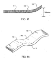
- Figure 17 illustrates the resultant shape of sheet 72 when adjacent portions 78C and 78D are selected. It is assumed that the SMA was pre-trained to curve upward along its entire length. Thus, together, deflections in portions 78C and 78D contribute to a much larger total deflection.
- Figure 18 illustrates another possible resultant shape of layer 72 when sections 78B-39D are heated and the SMA was pre-trained to assume an S-shape.
- the SMA of sheet 72 can be trained before or after assembly. Training before assembly can be preferable when working with materials which would be damaged if trained together with the SMA, e.g., due to the high annealing temperatures.
- sheet 72 has a coating layer 92 as shown in Figure 20.
- Deflection sensors 94 are positioned on layer 92.
- Sensors 92 can be either angular deflections sensors, extension deflection sensors such as a strain gage, or bend sensors.
- a bend sensor is a strain gage disposed for measuring bending strain and thus angular deflection. All of these devices are well known in the art. In this case sensors 94 have been placed in locations corresponding to those of elements 76. Depending on the geometry and application different placement may be preferable.
- the electrical diagram with sensors 94 is shown in Figure 19.
- the dotted line represents elements mounted on sheet 72. While the connections to elements 76A-38D remain the same, all sensors 94A-94D are wired to control unit 88 via lines 96A-96D respectively. In this manner unit 88 can receive signals representative of the local deflection from each one of sensors 94A-94D individually.
- a shape memory 98 is connected to unit 88. Memory is capable of mapping the resultant shape of sheet 72 based on information delivered from sensors 94.
- memory 98 has an inventory of resultant shapes produced by known combinations of elements 76.
- memory 98 is capable of recalling mapped resultant shapes positions and storing new ones.
- memory 98 can also store the actual current values corresponding to intermediate shapes of adjacent portions. This means that in operation shapes can be recalled and stored at will.
- the embodiment is thus highly versatile and practical for any diverse applications, e.g., guiding catheters.
- Figure 21 shows yet another embodiment which differs from the above only in that sensors 94 are positioned between elements 76.
- Figure 22 shows another modification in which a temperature sensor 100 is mounted between elements 76. This is advantageous for monitoring the temperature of sheet 72. In a particularly preferred embodiment this data is stored in memory 98. Checking the temperature form sensor 100 during operation can prevent overheating and other related malfunctions. Of course, more than one thermal sensor 100 can be provided. Ideally, a number of such sensors 100 can be provided. Ideally, a number of such sensors 100 are optimally positioned on sheet 72.
- Figure 23 shows the embodiment of Figure 14 in the martensitic state encapsulated in a top coating layer 102.
- Layer 102 is applied to protect the electrical connections and elements 76 in particular from damaging environmental factors, e.g., corrosive environments.
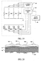
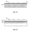
- Figure 24 and Figure 25 show two ways in which a two-dimensional sheet 104 of SMA can be cooled. For simplicity, all other elements, except for heating elements 108, have been omitted.
- the cooling element is a set of fins 106 in direct contact with sheet 104. This arrangement ensures efficient heat transfer and dissipation.
- the structure id Figure 25 efficiently dissipates heat using a substrate layer 110 with ducts 112 (only one shown).
- Ducts 112 carry a coolant, e.g., water, which absorbs and carries away the waste thermal energy.
Abstract
Description
- This application relates to an apparatus to treat an aneurism, and more particularly to a patch for treating an aneurism which is configured to form an adherence between the patch and an area of a vessel wall adjacent to an aneurism mouth and the adherence maintains a fixed position of the patch relative to the aneurism mouth.
- There are several devices which exist that are used for the repair of aneurysms. U.S. Patent No. 4,512,238 discloses a device for transluminal repair of, and restoring patency of, a weakened or damaged vessel uses a nitinol wire, previously memory-shaped into a straight wire and inserted into the vessel requiring repair. When placed in the body and stripped of heat insulation the wire warms and returns to a preselected coiled dimensions to support the vessel wall. One problem with this device is the difficult task of attaching a sleeve to the wire support because the wire is many times longer than the sleeve at the time it is inserted.
- U.S. Patent No. 4,140,126 discloses another device for repairing an aneurism. The device is mounted on the outside of a carrier catheter and is positioned in the vessel in a collapsed form, smaller in diameter that of the vessel. The device is then expanded onto the vessel well by the use of a separate mechanical expanding apparatus which is controlled by the user from outside the body.
- U.S. Patent No. 4, 787,899 describes a system of positioning a graft within a body lumen. The graft is loaded into a guide which is inserted into the lumen. An inflatable balloon is used to anchor the distal end of the graft onto the wall of the lumen. The guide is then pushed upstream, pulling the folded graft out of the guide and onto the wall of the lumen where staples end anchor it into the wall of the lumen. One problem with this device is that the balloon providing the anchor for the distal end of the graft while the guide is moved upstream may not provide enough pressure on the wall of the vessel to prevent slippage which could result in misplacement of the graft.
- An aneurysm patch apparatus as well as an aneurysm patch as defined in the preamble of
claims 1 and 23, respectively, are disclosed in WO-A-92/01425. - It would be desirable to provide an aneurism patch which does not have a coil configuration and which adheres to the vessel wall adjacent to the mouth of the aneurism. It would be further desirable to provide an aneurism patch which has non-electrically activated deployed state configured to be positioned adjacent to the mouth of the aneurism. Yet it would still further desirable to provide an aneurism patch which has an electrically activated deployed state that is configured to be positioned adjacent to the mouth of the aneurism.
- An object of the invention is to provide an apparatus for treating aneurysms.
- Another object of the invention is to provide an aneurism patch which is positioned over a mouth of an aneurism.
- Still another object of the invention is to provide an aneurism patch which has a non-electrically deployed state that is positioned over a mouth of an aneurism.
- Yet another object of the invention is to provide an aneurism patch which is introduced into a vessel in a stowed state and is positioned over the mouth of the aneurism in a deployed state.
- A further object of the invention is to provide an aneurism patch with a vessel interface side that includes a plurality of anchor elements.
- Still another object of the invention is to provide an aneurism patch forms a mechanical adherence between the patch and the vessel wall adjacent to the aneurism mouth.
- Yet another object of the invention is to provide an aneurism patch with an aperture configured to be coupled to a low pressure source.
- Another object of the invention is to provide an aneurism patch at least partially made of a material with an internal stress and a pre-defined shape, where the internal stress moves the patch from a stowed state to the pre-defined state.
- Still another object of the invention is provide an aneurism patch that is formed of a thermally active material that moves to a pre-defined shape when electrically heated.
- A further object of the invention is to provide an aneurism patch which is made of an SMA element with an activation threshold greater than body temperature.
- These and other objects of the invention are achieved in an aneurism patch apparatus for treating an aneurism formed in a vessel includes a patch with a vessel interface side and an opposing non-interface side. The patch is formed of a sufficiently flexible material to provide a patch stowed state when the patch is delivered through the vessel and a patch deployed state when the patch is at least partially positioned over the mouth of the aneurism. The interface side of the patch is configured to form an adherence between the patch and an area of a vessel wall adjacent to the aneurism mouth. The adherence maintains a fixed position of the patch relative to the aneurism mouth.
- In one embodiment of the invention the patch includes a vessel interface side and an opposing non-interface side, the patch is configured to have a stowed state when delivered to a mouth of the aneurism. The patch is formed of a thermally active material that moves to a pre-defined shape when electrically heated. The pre-defined shape forms an adherence between the vessel interface side and an area of the vessel -all adjacent to the aneurism mouth. The adherence maintains a fixed position of the patch relative to the aneurism mouth.
-
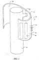
- Figure 1 is a perspective of an aneurism patch apparatus of the present invention.
- Figure 2 is a cross-sectional view of the patch of Figure 1 positioned adjacent to an aneurism.
- Figure 3 is a cross-sectional view of a patch positioned on an exterior surface of a catheter when the patch is in a stowed position.
- Figure 4 is a cross-sectional view of the patch in a deployed position and the evacuation of the aneurism through a lumen formed in the catheter.
- Figure 5 is a cross-sectional view of the patch in a deployed/pre-shaped position, the introduction of an adhesion medium and the collapse of the aneurism.
- Figure 6 is a cross-sectional view of the stowed patch positioned at a distal end of the catheter.
- Figure 7 is an isometric view of a deactivated two-dimensional sheet according to the invention.
- Figure 8 is an isometric view of the two-dimensional sheet of Figure 7 in the activated state.
- Figure 9 is an isometric view of a portion of the two-dimensional sheet of Figure 7.
- Figure 10A is a cross section of the portion of the two-dimensional of Figure 10A.
- Figure 10B is a graph of the temperature distribution in the portion of Figure 10A.
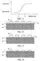
- Figure 11 is a graph of the transition between the martensitic and austenitic states as a function of temperature.
- Figure 12 is a cross section of a two-dimensional sheet with an insulating layer and a coating layer.
- Figure 13 is a cross section of a two-dimensional sheet with point-wise applied insulating layer and a coating layer.
- Figure 14 is a cross section of a two-dimensional sheet with a coating layer.
- Figure 15 is an exploded view illustrating the assembly of a two-dimensional sheet and the activation elements according to the invention.
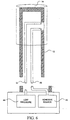
- Figure 16 is a diagram showing the equivalent circuit of the activation mechanism.
- Figure 17 is a side view illustrating the deflection of a two-dimensional sheet according to the invention.
- Figure 18 is a perspective view illustrating a complex pre-trained shape of a sheet according to an aspect of the invention.
- Figure 19 is a diagram showing the equivalent circuit of an embodiment using deflection sensors.
- Figure 20 is a cross sectional view of a two-dimensional sheet with deflection sensors.
- Figure 21 is a cross sectional view of a two-dimensional sheet with deflection sensors mounted next to heating elements.
- Figure 22 is a cross sectional view showing a two-dimensional sheet with a temperature sensor.
- Figure 23 is a cross sectional view of a two-dimensional sheet with protective coating applied over the eating elements.
- Figure 24 is a cross section of a two-dimensional sheet using vanes for heat dissipation.
- Figure 25 is a cross section of.a two-dimensional sheet using water ducts for heat dissipation.
-
- The present invention provides an aneurism patch apparatus for treating an aneurism formed in a vessel which includes a patch with a vessel interface side and an opposing non-interface side. The patch is formed of a sufficiently flexible material to provide a patch stowed state when the patch is delivered through the vessel and a patch deployed state when the patch is at least partially positioned over the mouth of the aneurism. The interface side of the patch is configured to form an adherence between the patch and an area of a vessel wall adjacent to the aneurism mouth. The adherence maintains a fixed position of the patch relative to the aneurism mouth.
- In one embodiment of the invention, the patch assumes the deployed state passively and is not electrically activated. In another embodiment, of the invention the patch is formed of a thermally active material that moves to a pre-defined shape when electrically heated. The pre-defined shape/deployed state forms the adherence between the vessel interface side and an area of the vessel wall adjacent to the aneurism mouth. In the pre-defined shape/deployed state, the patch has a circumference that is less than 360 degrees, more preferably less than 240 degrees and still more preferably less than 180 degrees. In the pre-defined shape/deployed state patch can have an interface side that is in substantial conformance (curvature) with the geometry of the adjacent vessel wall.
- Passive activation of the patch is achieved with a spring force that is inherent to the patch. This spring force can then drive one or more adhesive devices into the wall of the vessel surrounding the aneurism. Adhesion is achieved either by selecting materials for the patch which have internal spring forces, including SMA's and bimorphs, or with adhesion devices positioned on an interface surface of the patch to the vessel wall. Adhesion is non-frictional.
- Referring now to Figure 1, aneurism patch apparatus is denoted as 10 and optionally includes a delivery device, including but not limited to a
catheter 12. Apatch 14 is illustrated in a deployed state or in a pre-defined shape.Patch 14 has aninterface surface 16 and an opposingnon-interface surface 18. In one embodiment, an adhesive 20 is at least partially positioned oninterface surface 16.Patch 14 can be formed of a flexible material that is porous or non-porous and can include a stent type of geometry as well as a mesh. In one embodiment, one or moremechanical adhesion devices 22 are positioned oninterface 16 are become at least partially positioned in the vessel wall in which the aneurism is formed. Suitablemechanical devices 22 include but are not limited to the application of a vacuum or a low pressure source, barbs, hooks graspers, pinchers and the like. - When a vacuum is applied
adhesion devices 22 are forced into the surface of the vessel wall surrounding the aneurism mouth and anchor aneurism mouth down. Whenpatch 14 is porous a compliant shape is desirable betweeninterface surface 16 and the vessel wall surrounding the aneurism mouth. Additionally, with a porous patch 14 a spring force inherent inpatch 14 is used to driveadhesion devices 22 into the vessel wall. Other mechanical devices including but not limited to a balloon coupled tocannula 12 can be used to apply pressure oninterface surface 16 andadhesion devices 22.Patch 14 provides an internal force the area of the vessel adjacent to the aneurism. This force can be activated by thermal energy or mechanical energy inherent and/or applied to patch 14. Areleasable connector 24 couples patch 14 tocatheter 12. - Referring now to Figure 2,
patch 14 includes anaperture 26 that is configured to positioned over the mouth of the aneurism. In one embodiment,connector 24 includes a catheter connector 24(a) and a patch connector 24(b). Connectors 24(a) and 24(b) provide a mechanical release ofpatch 14 from catheter which can be an SMA element, devices that when activated pinch off a catheter lumen frompatch 14 can sever the two with a loop of wire or a heated wire that when pulled can cut, or an actual fabricated joint which is a release mechanism such as a catch. The SMA element can have an activation threshold greater than body temperature. - Figures 3 through 5 illustrate the positioning and release of
patch 14 ataneurism mouth 28. In Figure 3,patch 14 is in the stowed state and positioned on an exterior ofcatheter 12. In other embodiments,patch 14 can be positioned in an interior ofcatheter 12, and at a distal end ofcatheter 12. In the stowed state, the surface area ofpatch 14 is minimized to achieve access toaneurism mouth 28 for the treatment ofaneurism 30. - As illustrated in Figure 4,
patch 14 is in its deployed or pre-shaped state.Aperture 26 is positioned substantially overaneurism mouth 28. In Figure 4,catheter 12 is shown as having acatheter lumen 32 which provides for evacuation ofaneurism 30 whencatheter lumen 32 is coupled to a low pressure source, including but not limited to a vacuum source.Aneurism 30 is at a lower pressure than the rest of the of the vessel wall.Pressure 34, as shown with the arrows, is applied toaneurism 30, creating the possibility of creating a bursting ofaneurism 30. Couplinganeurism 30 to a low pressure source withcatheter lumen 32 begins an evacuation ofaneurysm 30. -
Patch 14 can include an SMA including but not limited to NiTi, a micro-fabricated circuit, a micro-fabricated sensor and a micro-fabricated transducer. Suitable micro-fabricated sensors include pressure, temperature, electosonic, voltage potential, chemical, chemical potential and electronic magnetic sensors. Suitable micro-fabricated transducer include temperature, electrosonic, voltage potential and electro magnetic transducers.Patch 14 can have a one-way of two-way shaped memory effect. - Figure 5 shows
aneurism 30 fully collapsed. Afteraneurism 30 is collapsed, adhesive 20 can be introduced through anintroduction lumen 36. Introduction lumen is coupled 36 is coupled to a source of adhesive 20 or other material of interest that can retainaneurism 30 in a contacting position withinterface surface 16. Such adhesives such as cyanacrylates, as known to those skilled in the art. -
Adhesive 20 can partially or fully fill an interstitial area 40, which is the volume occupied between theinterface surface 16 the surface of the vessel wall.Adhesive 20 can take up any irregularities between the vessel wall andinterface surface 16. - The use of the adhesive 20 is optional to provide a complete or a partial contacting relationship between
interface surface 16 and the vessel wall. Right. This is going, this is applying, so the blood within the vessel is applying pressure. - Figure 6 illustrates an
adhesive source 42 coupled tointroduction lumen 36 and alow pressure source 44 coupled tocatheter lumen 32. - The following discussion pertains to a suitable material for
patch 14 which is an SMA material or a bimorph. - A simplified embodiment of a two-
dimensional sheet 46 according to an aspect of the invention is shown in Figures 7, 8. The basic concepts discussed here can be applied directly to practical embodiments which will be described later. In thiscase sheet 46 is made entirely of a SMA chosen from the group of electrically conductive materials. Most common examples include NiTi alloys and CuZnAl alloys. Other alloys can also be used. The ratio of the thickness ofsheet 46 to the lateral extent ofheating element 48 should be preferably as small as possible, while still capable of maintaining the integrity ofsheet 46. -
SMA sheet 46 is produced by a variety of common machining methods; such as rolling of thin foils from were or thin plate stock, sectioning thin wafers from bar stock, or like methods. At present, sectioning of thin wafers from bar stock is preferred. Wafers of SMA material may be sliced from bar stock using a conventional band saw, a cold saw, an annular diamond wet saw, or electro-discharge machining (EDM) or like methods. The resulting wafer can be heat treated to a flat condition and precision-ground to any desired thickness. SMA bulk properties are assured as the material is obtained directly from bulk. The SMA material contained insheet 46 can be pre-trained prior to assembly or left untrained. The choice depends on the eventual application. - A plurality of
heating elements 48 are positioned on top ofSMA sheet 46 and insulated fromsheet 46 by an electrically insulatinglayer 50. It is most convenient to laminate or otherwise deposit electrically insulatinglayer 50 onsheet 46. Electrically insulatinglayer 50 prevents current leakage betweenheating elements 48 and electrically conductingsheet 46. Electrically insulatinglayer 50 also preferably is a good thermal conductor. Preferred insulating materials include polyimide or silicon nitride SixNy. The thickness of electrically insulatinglayer 50 should be small in relation to its lateral extent. For example, electrically insulatinglayer 50 may be a 2000Å silicon nitride layer to ensure adequate thermal coupling, and to ensure thermal conductivity betweenheating elements 48 andsheet 46. - In the simplified embodiment of Figures 7, 8,
heating elements 48 are in the form of thin film resistors. Most preferably,heating elements 48 are ohmic heaters or other similar devices capable of converting electrical current to thermal energy. They can comprise any conventional resistive material such as TiW or TaO. Conveniently, the resistive material is first deposited and patterned onlayer 50 by well known VLSI or micro-machining techniques. Then,heating elements 48 are patterned or otherwise formed according to well-known techniques. - In Figure 9 the thickness of
sheet SMA 46 is labeled by S. For clarity, aparticular heating element 48X has been selected to explain the details of the invention.Heating element 48X has associated with it anadjacent portion 52X ofSMA sheet 46. As shown,heating element 48X has associated with it asection 54X of electrically insulatinglayer 50 as well.Portion 52X is located directly underneathheating element 48X. The width ofportion 52X is denoted by D. As shown,heating element 48X provides heat toportion 52X exclusively. Heat propagates throughsection 54X and intosection 52X which represents a localized portion ofSMA sheet 46. - The operation of the simplified embodiment is best understood by comparing Figure 7 and Figure 8. In this case, the SMA material has been pre-trained to assume a predetermined shape when thermally activated to an activation threshold temperature. In FIG 7,
SMA sheet 46 is shown in an inactive state. - Figure 8 shows a particular case wherein six
heating elements 48, labeled as 52A-F, are providing heat. Consequently, the heat traverses section 54A-18F of insulatinglayer 50 and causesadjacent portions 52A-16F ofSMA sheet 46 to reach activation threshold. As a result, portions of 52A-16F assume a well-defined shape and in the process, provide useful activation forces. As shown, the local deformation is upward convex. Onceportions 52A-F assume their shape, the areas ofsheet 46 surrounding those portions deform in accordance with a predetermined memory characteristic. In fact,entire sheet 46 assumes a resultant shape due to local changes as dictated by its geometry. In the simple case of Figure 8, the remainder ofsheet 46 remains flat or otherwise returns to its neutral shape; neutral meaning its inactive state. More complex resultant shapes will be described in later embodiments. - The principles behind the heating process and the shape assumed by adjacent portions 52 are best illustrated in Figure 10A. We consider one
heating element 48X. For clarity, the predetermined shape assumed byadjacent portion 52X upon heating has not been shown. The heat generated byelement 48X, whose width is indicated by W, passes along arrows through insulatinglayer 50. In particular, the thermal energy traversessection 54X oflayer 50.Layer 50 is proportionally very thin compared to the lateral dimensions, and thussection 54X readily transfers the heat tosheet 46. Once insheet 46 the heat propagates throughoutadjacent portion 52X. - Graph 10B represents temperature distributions at an arbitrary fixed depth below
heater 48X. The graph in Figure 10B shows the temperature distribution laterally, in the X direction, insideportion 52X. Directly underelement 48X the temperature remains at a maximum, as indicated by the flat portion of the curve from -W/2 to +W/2. In other words, the heat delivered toportion 52X does not propagate to other portions 52, e.g.,portion 52Y. Instead, the heat radiates along arrows R out ofsheet 46 before reaching other portions 52. - As already mentioned, the shape of adjacent portions 52 depends on the pre-trained shape of the SMA or
sheet 46 in those regions. Also, the shape depends on the temperature maintained in portions 52. Full conformity to the pre-trained shape is achieved when the temperature in portions 52 is equal or higher than the critical temperature at which the SMA material attains the austenitic state. This is best shown in the graph of Figure 5. At temperatures below T1 the SMA material remains pliable, as dictated by the martensitic properties. Therefore, portions 52 maintained at or below T1 will conform to the shape imparted to them by the surroundings. The transition to the austenitic state occurs between temperatures T1 and T2. When portions 52 are kept in this temperature range they will assume an intermediate shape between the relaxed and pre-trained forms. Careful thermal regulation thus allows one to vary the shape of any portions 52 ofsheet 46 in a continuous manner. - The overall structure of
sheet 46 whereheating elements 48 are mounted directly onsheet 46 withonly layer 50 interposed between them is very simple. The assembly process is straightforward and low-cost. - Another embodiment of the invention is shown in Figure 11. Here a two-
dimensional sheet 56 of SMA material is placed on acoating layer 58. In this case,layer 58 is sufficiently thick to provide mechanical stability. - A thin insulating
layer 60 is disposed on top ofsheet 56 to provide electrical insulation betweenheating elements 62 andsheet 56.Layer 60 is thin enough and has appropriate thermal properties to permit the free flow of heat fromelements 62 tosheet 56. In this embodiment the SMA material ofsheet 56 is also electrically conducting (e.g., TiNi alloy or CuZnAl alloy). - The operation of this embodiment is analogous to the operation of the first one. The added stability of
coating layer 58 ensures conformity to a well-defined shape when all portions ofsheet 56 are in the martensitic state. - The embodiment of Figure 12
exhibits sheet 56 of electrically conducting SMA with acoating layer 68 acting as substrate. In thiscase layer 68 is chosen from materials which are chemically inert and stable to protectsheet 56 from adverse effects. - Electrical insulation between
heating elements 62 andsheet 56 is provided by sections ofelectrical insulation sections 64 deposited point-wise underelements 62. Such structure can be produced by initially applying a layer of insulating material and a layer of heating material. Then,elements 62 and a correspondingelectrical insulation sections 64 are fashioned by etching or another well-known process. Preferably, a well known VLSI technique or a micro-machining technique is employed for this purpose. - Figure 13 shows yet another embodiment in which a two-
dimensional sheet 70 is made up of an electrically insulating SMA material. In this configuration no insulation is necessary. Consequently,heating elements 62 are mounted directly onsheet 70. Acoating layer 68 functioning as substrate is once again provided to afford mechanical stability and resistance. It is preferable thatlayer 68 also be a good thermal conductor to aid in the dissipation of heat fromsheet 70. - The embodiments of FIGS. 11-13 all operate in the manner set forth above. The modifications introduced are intended to aid one skilled in the art in selecting the appropriate structure given a set of technical requirements.
- A preferred embodiment is shown in Figure 15. A two-
dimensional sheet 72 of an electrically conducting SMA material, preferably a NiTi alloy is coated with insulatinglayer 74. Preferably,layer 74 is made of SixNy or polyimide and is sufficiently thin to readily conduct heat. - Patterned
heating elements 76 are located onlayer 74.Elements 76 are obtained by first sputtering TiW or TaO on top oflayer 74 and then performing a patterning step.Heating elements 76 offer a very high resistance. In thepreferred embodiment elements 76 have a zig-zag shape. This enables them to ensure better heat distribution insheet 72 when active. - A second insulating
layer 80 is provided on top ofelements 76 andlayer 74. Preferably,layer 80 is made of a flexible electrical insulation such as polyimide, which can be spun coated ontoelements 76 andlayer 74. A number of through-holes 86 are opened inlayer 80 to permit electrical contact withelements 76.Holes 86 are sensibly aligned with the terminal portions ofelements 76. - A set of conduction lines 82 are patterned on top of
layer 80. Preferably, conduction lines 82 are made of a flexible and highly conductive material such as gold. Lines 82 can be defined by patterning or other suitable techniques. Acommon return line 82A is laid out to provide electrical contact with the left terminals of allelements 76.Return line 82A saves surface area of top oflayer 80 and is desirable as long as allelements 76 are not addressed simultaneously on a continuous basis. If continuous activation is required, then an additional full width layer would be dedicated for the return path. The other lines, 82B-42E are in electrical contact with the right terminals ofelements 76 respectively. - External electrical connections are made to contact
pads 84A-84E, corresponding tolines 82A-42E. For this purpose,pads 84A-84E are designed much thicker thanlines 82A-42E. The actual electric connections are made with wire bonding or similar means. - Once the entire structure on
sheet 72 is assembled, the SMA is "trained" by forcingsheet 72 to assume a resultant shape using well-known methods. For example,sheet 72 is formed on a mandrel and fixed in place with a clamp. The entire fixture is then placed in an annealing furnace, preferably purged with an inert gas, at approximately 450 C for about 30 minutes. Upon cooling the film is released from the mandrel. At thistime sheet 72 is operationally ready. - The electrical diagram showing the electrical connections of the preferred embodiment is found in Figure 16. A
control unit 88 is connected to acurrent supply 90. Preferably, bothunit 88 andsupply 90 are located away fromsheet 72.Unit 88 is preferably a micro-processor capable of selecting a desired combination ofelements 76.Current supply 90 is preferably an adjustable source capable of delivering current to the selected combination ofelements 76.Lines 82A-42E are connected directly to supply 90.Elements 76A-76D are shown as resistors.Return line 82A is grounded. - During
operation control unit 88 selects a combination ofelements 76 to be activated. It then sends a corresponding command to supply 90.Supply 90 responds by delivering current toelements 76 of the chosen combination. For example,elements elements adjacent portions 78A and 78D assume a well-defined shape. If the current is sufficiently large and the temperature maintained inadjacent portions 78A and 78D is above T2 (see Figure 5) thenportions 78A and 78D will assume their pre-trained shape. If the temperature is between T1 and T2 portions 78A and 78D will assume an intermediate shape. Becausesupply 90 is adjustable the proper current can be selected during operation and adjusted on an empirical basis. Consequently, the shape ofportions 78A and 78D can be varied as necessary. - Figure 17 illustrates the resultant shape of
sheet 72 whenadjacent portions portions layer 72 whensections 78B-39D are heated and the SMA was pre-trained to assume an S-shape. Throughout the description it is understood that the SMA ofsheet 72 can be trained before or after assembly. Training before assembly can be preferable when working with materials which would be damaged if trained together with the SMA, e.g., due to the high annealing temperatures. - In another embodiment similar to the
preferred embodiment sheet 72 has acoating layer 92 as shown in Figure 20. For better understanding, the deflections insheet 72 have been indicated. Deflection sensors 94 are positioned onlayer 92.Sensors 92 can be either angular deflections sensors, extension deflection sensors such as a strain gage, or bend sensors. A bend sensor is a strain gage disposed for measuring bending strain and thus angular deflection. All of these devices are well known in the art. In this case sensors 94 have been placed in locations corresponding to those ofelements 76. Depending on the geometry and application different placement may be preferable. - The electrical diagram with sensors 94 is shown in Figure 19. The dotted line represents elements mounted on
sheet 72. While the connections toelements 76A-38D remain the same, allsensors 94A-94D are wired to controlunit 88 via lines 96A-96D respectively. In thismanner unit 88 can receive signals representative of the local deflection from each one ofsensors 94A-94D individually. Ashape memory 98 is connected tounit 88. Memory is capable of mapping the resultant shape ofsheet 72 based on information delivered from sensors 94. - Preferably,
memory 98 has an inventory of resultant shapes produced by known combinations ofelements 76. In other words,memory 98 is capable of recalling mapped resultant shapes positions and storing new ones. In the mostpreferred embodiment memory 98 can also store the actual current values corresponding to intermediate shapes of adjacent portions. This means that in operation shapes can be recalled and stored at will. The embodiment is thus highly versatile and practical for any diverse applications, e.g., guiding catheters. - Figure 21 shows yet another embodiment which differs from the above only in that sensors 94 are positioned between
elements 76. Figure 22 shows another modification in which atemperature sensor 100 is mounted betweenelements 76. This is advantageous for monitoring the temperature ofsheet 72. In a particularly preferred embodiment this data is stored inmemory 98. Checking thetemperature form sensor 100 during operation can prevent overheating and other related malfunctions. Of course, more than onethermal sensor 100 can be provided. Ideally, a number ofsuch sensors 100 can be provided. Ideally, a number ofsuch sensors 100 are optimally positioned onsheet 72. - Figure 23 shows the embodiment of Figure 14 in the martensitic state encapsulated in a
top coating layer 102.Layer 102 is applied to protect the electrical connections andelements 76 in particular from damaging environmental factors, e.g., corrosive environments. - Figure 24 and Figure 25 show two ways in which a two-
dimensional sheet 104 of SMA can be cooled. For simplicity, all other elements, except forheating elements 108, have been omitted. In Figure 24 the cooling element is a set offins 106 in direct contact withsheet 104. This arrangement ensures efficient heat transfer and dissipation. Similarly, the structure id Figure 25 efficiently dissipates heat using a substrate layer 110 with ducts 112 (only one shown).Ducts 112 carry a coolant, e.g., water, which absorbs and carries away the waste thermal energy. - While the invention has been described in connection with what is presently considered to be the most practical and preferred embodiments, it is to be understood that the invention is not limited to the disclosed embodiments, but on the contrary, is intended to cover various modifications and equivalent arrangements included within the scope of the appended claims. For example, a Peltier device could also provide an equivalent solution to heat dissipation. Therefore, persons of ordinary skill in this field are to understand that all such equivalent structures are to be included within the scope of the following claims.
Claims (33)
- An aneurysm patch apparatus (10) for treating an aneurysm, the apparatus comprising an aneurysm patch (14) and an insertion tool (12), wherein:characterised in that the mounting means (24b) are positioned on the aneurysm patch at a region of the patch remote from its margin.the aneurysm patch is laminar in form and has a substantially tubular furled condition and a deployed condition in which the patch is non-tubular;the aneurysm patch is detachably mountable to the insertion tool, and comprises mounting means (24b) for mounting the aneurysm patch to the insertion tool,
- An aneurysm patch apparatus according to claim 1, wherein the aneurysm patch is detachably mountable to the exterior of a distal end of the insertion tool.
- An aneurysm patch apparatus according to claim 1 or claim 2, wherein the insertion tool comprises mounting means (24a) adapted to cooperate with the mounting means (24b) of the patch (14) to releasably couple the patch (14) and the tool (12).
- An aneurysm patch apparatus according to claim 3, wherein the mounting means (24a) of the tool (12) and the mounting means (24b) of the patch (14) comprise selectively releaseable mechanical connectors.
- An aneurysm patch apparatus according to claim 3, wherein the mounting means (24a) of the tool (12) and the mounting means (24b) of the patch (14) comprise a thermally activatable releaseable connection.
- An aneurysm patch apparatus according to claim 3, wherein the mounting means (24a) of the tool (12) and the mounting means (24b) of the patch (14) comprise an electrically activatable releaseable connection.
- An aneurysm patch apparatus according to any preceding claim wherein the patch has a vessel interface side (16) and an opposing non-interface side (18) and an opening (26) in a central region of the patch extending through the patch from the vessel interface side to the non-interface side.
- An aneurysm patch apparatus according to any preceding claim, wherein the insertion tool is elongate and has a radially extending projection (24, 24a) with a lumen, and the mounting means (24b) of the patch (14) comprises an opening (26) in a central region of the patch, and wherein when the aneurysm patch is mounted to the insertion tool the lumen of the projection (24) of the tool (12) is aligned with the opening in the patch.
- An aneurysm patch apparatus according to any preceding claim wherein the patch has a vessel interface side (16) and an opposing non-interface side (18) and the patch comprises adhesion devices (22) on its vessel interface side (16).
- An aneurysm patch apparatus according to claim 9, wherein the adhesion devices (22) are mechanical and comprise barbs, hooks, or pinchers.
- An aneurysm patch apparatus according to claim 9, wherein the adhesion devices (22) comprise areas of adhesive (20) formed on the vessel interface side (16) of the patch (14).
- An aneurysm patch apparatus according to any preceding claim, wherein the insertion tool includes a lumen (32, 36) aligned with the opening (26) of the patch.
- An aneurysm patch apparatus according to claim 12, wherein the insertion tool includes means for coupling a source (44) of low pressure through the lumen (32) to the vessel interface side of the patch.
- An aneurysm patch apparatus according to claim 12 or claim 13, wherein the insertion tool includes means for delivering an adhesive (20) or other material of interest from a source (42) through the lumen (36) to the vessel interface side of the patch.
- An aneurysm patch apparatus according to any preceding claim, wherein the patch (14) is formed from an elastic material and moves from its furled position to its deployed position passively.
- An aneurysm patch apparatus according to any of claims 1 to 15, wherein the patch (14) is at least partially formed from a thermally active material and moves from its furled position to its deployed position when heated.
- An aneurysm patch apparatus according to claim 16, wherein the patch comprises heating elements (48) selectively operable to heat the patch to move the patch toward its deployed position.
- An aneurysm patch apparatus according to claim 16 or claim 17, wherein the patch is formed at least partially from NiTi alloy.
- An aneurysm patch apparatus according to any of claims 16 to 18, wherein the patch comprises sensor or transducer circuits for detecting pressure, temperature, electrical potential, or magnetic fields.
- An aneurysm patch apparatus according to any preceding claim, wherein the patch is part-cylindrical in form when deployed.
- An aneurysm patch apparatus according to claim 20, wherein the patch extends round 240 degrees or less of a cylinder when deployed.
- An aneurysm patch apparatus according to claim 20, wherein the patch extends round 180 degrees or less of a cylinder when deployed.
- An aneurysm patch for use in an apparatus according to- any preceding claim, the patch comprising a flexible laminar patch member (14) movable from a substantially tubular furled position to a deployed condition in which the patch is non-tubular, the patch having a vessel interface side (16) and an opposing non-interface side (18) and mounting means (24b) for releasably mounting the aneurysm patch to an insertion tool (12),
characterised in that the mounting means (24b) are positioned on the aneurysm patch at a region of the patch remote from its margin. - An aneurysm patch according to claim 23, wherein the mounting means (24b) comprises an opening (26) in a central region of the patch extending through the patch from the vessel interface side to the non-interface side.
- An aneurysm patch according to claim 23 or claim 24, wherein the patch (14) is formed from an elastic material and moves from its furled position to its deployed position passively.
- An aneurysm patch according to claim 23 or claim 24, wherein the patch (14) is formed from a thermally active material and moves from its furled position toward its deployed position when heated.
- An aneurysm patch according to claim 26, wherein the patch comprises heating element (48) operable to heat the patch to move the patch toward its deployed position.
- An aneurysm patch according to claim 27, wherein the patch comprises a plurality of heating elements (48) selectively operable to heat the patch to move the patch toward its deployed position.
- An aneurysm patch according to any of claims 26 to 28, wherein the patch is formed at least partially from NiTi alloy.
- An aneurysm patch according to any of claims 26 to 29, wherein the patch comprises sensor or transducer circuits for detecting pressure, temperature, electrical potential, or magnetic fields.
- An aneurysm patch according to any of claims 23 to 30, wherein the patch is part-cylindrical in form when deployed.
- An aneurysm patch according to claim 31, wherein the patch extends round 240 degrees or less of a cylinder when deployed.
- An aneurysm patch according to claim 31, wherein the patch extends round 180 degrees or less of a cylinder when deployed.
Applications Claiming Priority (3)
| Application Number | Priority Date | Filing Date | Title |
|---|---|---|---|
| US08/756,099 US5941249A (en) | 1996-09-05 | 1996-11-25 | Distributed activator for a two-dimensional shape memory alloy |
| US756099 | 1996-11-25 | ||
| PCT/US1997/019392 WO1998023227A1 (en) | 1996-11-25 | 1997-10-29 | Aneurysm patch apparatus and method for treating an aneurysm |
Publications (2)
| Publication Number | Publication Date |
|---|---|
| EP0957823A1 EP0957823A1 (en) | 1999-11-24 |
| EP0957823B1 true EP0957823B1 (en) | 2005-06-29 |
Family
ID=25042042
Family Applications (1)
| Application Number | Title | Priority Date | Filing Date |
|---|---|---|---|
| EP97946316A Expired - Lifetime EP0957823B1 (en) | 1996-11-25 | 1997-10-29 | Aneurysm patch apparatus |
Country Status (8)
| Country | Link |
|---|---|
| US (2) | US5941249A (en) |
| EP (1) | EP0957823B1 (en) |
| JP (1) | JP4142108B2 (en) |
| AT (1) | ATE298543T1 (en) |
| AU (1) | AU5151298A (en) |
| CA (1) | CA2272655C (en) |
| DE (1) | DE69733667T2 (en) |
| WO (1) | WO1998023227A1 (en) |
Families Citing this family (156)
| Publication number | Priority date | Publication date | Assignee | Title |
|---|---|---|---|---|
| US6475170B1 (en) * | 1997-12-30 | 2002-11-05 | Remon Medical Technologies Ltd | Acoustic biosensor for monitoring physiological conditions in a body implantation site |
| US20030036746A1 (en) | 2001-08-16 | 2003-02-20 | Avi Penner | Devices for intrabody delivery of molecules and systems and methods utilizing same |
| US7044134B2 (en) | 1999-11-08 | 2006-05-16 | Ev3 Sunnyvale, Inc | Method of implanting a device in the left atrial appendage |
| US7128073B1 (en) | 1998-11-06 | 2006-10-31 | Ev3 Endovascular, Inc. | Method and device for left atrial appendage occlusion |
| US20020169473A1 (en) | 1999-06-02 | 2002-11-14 | Concentric Medical, Inc. | Devices and methods for treating vascular malformations |
| US6375668B1 (en) | 1999-06-02 | 2002-04-23 | Hanson S. Gifford | Devices and methods for treating vascular malformations |
| US6231561B1 (en) | 1999-09-20 | 2001-05-15 | Appriva Medical, Inc. | Method and apparatus for closing a body lumen |
| US6551303B1 (en) | 1999-10-27 | 2003-04-22 | Atritech, Inc. | Barrier device for ostium of left atrial appendage |
| US6652555B1 (en) | 1999-10-27 | 2003-11-25 | Atritech, Inc. | Barrier device for covering the ostium of left atrial appendage |
| US6689150B1 (en) | 1999-10-27 | 2004-02-10 | Atritech, Inc. | Filter apparatus for ostium of left atrial appendage |
| US6994092B2 (en) * | 1999-11-08 | 2006-02-07 | Ev3 Sunnyvale, Inc. | Device for containing embolic material in the LAA having a plurality of tissue retention structures |
| US6730104B1 (en) | 2000-06-29 | 2004-05-04 | Concentric Medical, Inc. | Methods and devices for removing an obstruction from a blood vessel |
| US8298257B2 (en) | 2000-06-29 | 2012-10-30 | Concentric Medical, Inc. | Systems, methods and devices for removing obstructions from a blood vessel |
| JP2004506469A (en) * | 2000-08-18 | 2004-03-04 | アトリテック, インコーポレイテッド | Expandable implantable device for filtering blood flow from the atrial appendage |
| JP2004508879A (en) | 2000-09-21 | 2004-03-25 | アトリテック, インコーポレイテッド | Apparatus for implanting a device in the atrial appendage |
| JP2005508201A (en) * | 2001-03-08 | 2005-03-31 | アトリテック, インコーポレイテッド | Atrial filter implant |
| EP1392394A4 (en) * | 2001-06-04 | 2005-05-18 | Albert Einstein Healthcare Network | Cardiac stimulating apparatus having a blood clot filter and atrial pacer |
| US7011671B2 (en) * | 2001-07-18 | 2006-03-14 | Atritech, Inc. | Cardiac implant device tether system and method |
| US7572288B2 (en) * | 2001-07-20 | 2009-08-11 | Microvention, Inc. | Aneurysm treatment device and method of use |
| US8252040B2 (en) | 2001-07-20 | 2012-08-28 | Microvention, Inc. | Aneurysm treatment device and method of use |
| US8715312B2 (en) | 2001-07-20 | 2014-05-06 | Microvention, Inc. | Aneurysm treatment device and method of use |
| US7669799B2 (en) * | 2001-08-24 | 2010-03-02 | University Of Virginia Patent Foundation | Reversible shape memory multifunctional structural designs and method of using and making the same |
| CA2474324C (en) | 2002-01-25 | 2011-09-20 | Atritech, Inc. | Atrial appendage blood filtration systems |
| CA2487934A1 (en) * | 2002-05-30 | 2003-12-11 | University Of Virginia Patent Foundation | Active energy absorbing cellular metals and method of manufacturing and using the same |
| US8075585B2 (en) * | 2002-08-29 | 2011-12-13 | Stryker Corporation | Device and method for treatment of a vascular defect |
| US6832478B2 (en) * | 2003-04-09 | 2004-12-21 | Medtronic, Inc. | Shape memory alloy actuators |
| US7658709B2 (en) * | 2003-04-09 | 2010-02-09 | Medtronic, Inc. | Shape memory alloy actuators |
| US20060286342A1 (en) * | 2003-05-28 | 2006-12-21 | Elzey Dana M | Re-entrant cellular multifunctional structure for energy absorption and method of manufacturing and using the same |
| US7632291B2 (en) | 2003-06-13 | 2009-12-15 | Trivascular2, Inc. | Inflatable implant |
| US20040260384A1 (en) * | 2003-06-17 | 2004-12-23 | Medtronic Ave | Superelastic coiled stent |
| US7118652B2 (en) * | 2003-12-04 | 2006-10-10 | General Motors Corporation | Airflow control devices based on active materials |
| US7059664B2 (en) * | 2003-12-04 | 2006-06-13 | General Motors Corporation | Airflow control devices based on active materials |
| US6979050B2 (en) * | 2003-12-04 | 2005-12-27 | General Motors Corporation | Airflow control devices based on active materials |
| WO2005069996A2 (en) * | 2004-01-02 | 2005-08-04 | Js Vascular Inc. | Monocusp valve construction and defect closure device for deep vein regurgitation |
| US20050197687A1 (en) * | 2004-03-02 | 2005-09-08 | Masoud Molaei | Medical devices including metallic films and methods for making same |
| US8998973B2 (en) | 2004-03-02 | 2015-04-07 | Boston Scientific Scimed, Inc. | Medical devices including metallic films |
| US20060142838A1 (en) * | 2004-12-29 | 2006-06-29 | Masoud Molaei | Medical devices including metallic films and methods for loading and deploying same |
| US8632580B2 (en) | 2004-12-29 | 2014-01-21 | Boston Scientific Scimed, Inc. | Flexible medical devices including metallic films |
| US8591568B2 (en) | 2004-03-02 | 2013-11-26 | Boston Scientific Scimed, Inc. | Medical devices including metallic films and methods for making same |
| US8992592B2 (en) * | 2004-12-29 | 2015-03-31 | Boston Scientific Scimed, Inc. | Medical devices including metallic films |
| US7901447B2 (en) | 2004-12-29 | 2011-03-08 | Boston Scientific Scimed, Inc. | Medical devices including a metallic film and at least one filament |
| US8271093B2 (en) | 2004-09-17 | 2012-09-18 | Cardiac Pacemakers, Inc. | Systems and methods for deriving relative physiologic measurements using a backend computing system |
| US8845676B2 (en) | 2004-09-22 | 2014-09-30 | Micro Therapeutics | Micro-spiral implantation device |
| EP1793744B1 (en) | 2004-09-22 | 2008-12-17 | Dendron GmbH | Medical implant |
| US7854467B2 (en) * | 2004-11-05 | 2010-12-21 | General Motors Corporation | Airflow control devices based on active materials |
| US7813808B1 (en) | 2004-11-24 | 2010-10-12 | Remon Medical Technologies Ltd | Implanted sensor system with optimized operational and sensing parameters |
| US7854760B2 (en) | 2005-05-16 | 2010-12-21 | Boston Scientific Scimed, Inc. | Medical devices including metallic films |
| US7742815B2 (en) | 2005-09-09 | 2010-06-22 | Cardiac Pacemakers, Inc. | Using implanted sensors for feedback control of implanted medical devices |
| US7972359B2 (en) | 2005-09-16 | 2011-07-05 | Atritech, Inc. | Intracardiac cage and method of delivering same |
| EP1951129B1 (en) | 2005-10-19 | 2012-11-21 | Pulsar Vascular, Inc. | Methods and systems for endovascularly clipping and repairing lumen and tissue defects |
| US7278679B2 (en) * | 2005-10-26 | 2007-10-09 | Ford Global Technologies, Llc | Automotive vehicle with structural panel having selectively deployable shape memory alloy elements |
| US9402633B2 (en) | 2006-03-13 | 2016-08-02 | Pneumrx, Inc. | Torque alleviating intra-airway lung volume reduction compressive implant structures |
| US8888800B2 (en) | 2006-03-13 | 2014-11-18 | Pneumrx, Inc. | Lung volume reduction devices, methods, and systems |
| US8157837B2 (en) | 2006-03-13 | 2012-04-17 | Pneumrx, Inc. | Minimally invasive lung volume reduction device and method |
| US8864790B2 (en) | 2006-04-17 | 2014-10-21 | Covidien Lp | System and method for mechanically positioning intravascular implants |
| US8777979B2 (en) | 2006-04-17 | 2014-07-15 | Covidien Lp | System and method for mechanically positioning intravascular implants |
| US8360361B2 (en) | 2006-05-23 | 2013-01-29 | University Of Virginia Patent Foundation | Method and apparatus for jet blast deflection |
| US7955268B2 (en) | 2006-07-21 | 2011-06-07 | Cardiac Pacemakers, Inc. | Multiple sensor deployment |
| DE102006049378A1 (en) * | 2006-10-19 | 2008-04-24 | Siemens Ag | Implant i.e. electrical passive implant, jointing knee of patient, has passive radio frequency identification unit coupled with deformation sensors, for monitoring sensor value, where sensors are implemented as servicing interface |
| US7677639B2 (en) * | 2007-02-23 | 2010-03-16 | Gm Global Technology Operations, Inc. | Active material based closure hinge and alignment process |
| CN101677821B (en) | 2007-03-13 | 2014-05-14 | 泰科保健集团有限合伙公司 | Implant and mandrel |
| CA2680607C (en) | 2007-03-13 | 2015-07-14 | Microtherapeutics, Inc. | An implant including a coil and a stretch-resistant member |
| EP3111869B1 (en) | 2007-03-15 | 2017-09-20 | Ortho-Space Ltd. | System of sealing an inflatable prosthesis |
| EP2149704A4 (en) * | 2007-05-11 | 2016-06-08 | Nat Inst For Materials Science | Two-direction shape-memory alloy thin film actuator and method for manufacturing shape-memory alloy thin film used in the actuator |
| CA2704920C (en) | 2007-06-25 | 2016-08-16 | Microvention, Inc. | Self-expanding prosthesis |
| US8226701B2 (en) | 2007-09-26 | 2012-07-24 | Trivascular, Inc. | Stent and delivery system for deployment thereof |
| US8066755B2 (en) | 2007-09-26 | 2011-11-29 | Trivascular, Inc. | System and method of pivoted stent deployment |
| US8663309B2 (en) | 2007-09-26 | 2014-03-04 | Trivascular, Inc. | Asymmetric stent apparatus and method |
| BRPI0817488A2 (en) | 2007-10-04 | 2017-05-16 | Trivascular Inc | low percutaneous profile modular vascular graft |
| US8083789B2 (en) | 2007-11-16 | 2011-12-27 | Trivascular, Inc. | Securement assembly and method for expandable endovascular device |
| US8328861B2 (en) | 2007-11-16 | 2012-12-11 | Trivascular, Inc. | Delivery system and method for bifurcated graft |
| EP2242538B1 (en) | 2008-02-11 | 2016-04-06 | Cardiac Pacemakers, Inc. | Methods of monitoring hemodynamic status for ryhthm discrimination within the heart |
| WO2009102640A1 (en) | 2008-02-12 | 2009-08-20 | Cardiac Pacemakers, Inc. | Systems and methods for controlling wireless signal transfers between ultrasound-enabled medical devices |
| EP2633823B1 (en) | 2008-04-21 | 2016-06-01 | Covidien LP | Braid-ball embolic devices and delivery systems |
| US10716573B2 (en) | 2008-05-01 | 2020-07-21 | Aneuclose | Janjua aneurysm net with a resilient neck-bridging portion for occluding a cerebral aneurysm |
| JP2011519300A (en) * | 2008-05-01 | 2011-07-07 | アニュクローズ エルエルシー | Aneurysm occlusion device |
| US10028747B2 (en) | 2008-05-01 | 2018-07-24 | Aneuclose Llc | Coils with a series of proximally-and-distally-connected loops for occluding a cerebral aneurysm |
| US9675482B2 (en) | 2008-05-13 | 2017-06-13 | Covidien Lp | Braid implant delivery systems |
| CN102137626A (en) | 2008-07-22 | 2011-07-27 | 微治疗公司 | Vascular remodeling device |
| CN102202585B (en) | 2008-09-05 | 2014-04-02 | 帕尔萨脉管公司 | Systems and methods for supporting or occluding a physiological opening or cavity |
| US8632605B2 (en) | 2008-09-12 | 2014-01-21 | Pneumrx, Inc. | Elongated lung volume reduction devices, methods, and systems |
| JP5465252B2 (en) | 2008-10-10 | 2014-04-09 | カーディアック ペースメイカーズ, インコーポレイテッド | System and method for determining cardiac output using pulmonary artery pressure measurements |
| US8632470B2 (en) | 2008-11-19 | 2014-01-21 | Cardiac Pacemakers, Inc. | Assessment of pulmonary vascular resistance via pulmonary artery pressure |
| US20100131002A1 (en) * | 2008-11-24 | 2010-05-27 | Connor Robert A | Stent with a net layer to embolize and aneurysm |
| WO2010135352A1 (en) | 2009-05-18 | 2010-11-25 | Pneumrx, Inc. | Cross-sectional modification during deployment of an elongate lung volume reduction device |
| JP5731512B2 (en) | 2009-09-04 | 2015-06-10 | パルサー バスキュラー インコーポレイテッド | System and method for sealing an anatomical opening |
| US20110202085A1 (en) | 2009-11-09 | 2011-08-18 | Siddharth Loganathan | Braid Ball Embolic Device Features |
| US9358140B1 (en) | 2009-11-18 | 2016-06-07 | Aneuclose Llc | Stent with outer member to embolize an aneurysm |
| US8906057B2 (en) * | 2010-01-04 | 2014-12-09 | Aneuclose Llc | Aneurysm embolization by rotational accumulation of mass |
| EP2528541B1 (en) | 2010-01-28 | 2016-05-18 | Covidien LP | Vascular remodeling device |
| WO2011094638A1 (en) | 2010-01-28 | 2011-08-04 | Micro Therapeutics, Inc. | Vascular remodeling device |
| US8425548B2 (en) | 2010-07-01 | 2013-04-23 | Aneaclose LLC | Occluding member expansion and then stent expansion for aneurysm treatment |
| JP5757518B2 (en) * | 2011-01-13 | 2015-07-29 | 国立研究開発法人物質・材料研究機構 | Method for manufacturing thin film actuator |
| CA2825774C (en) | 2011-02-11 | 2017-02-28 | Frank P. Becking | Two-stage deployment aneurysm embolization devices |
| WO2012134990A1 (en) | 2011-03-25 | 2012-10-04 | Tyco Healthcare Group Lp | Vascular remodeling device |
| US10058330B2 (en) | 2011-05-11 | 2018-08-28 | Microvention, Inc. | Device for occluding a lumen |
| US9138232B2 (en) | 2011-05-24 | 2015-09-22 | Aneuclose Llc | Aneurysm occlusion by rotational dispensation of mass |
| KR102018035B1 (en) | 2011-06-03 | 2019-09-05 | 펄사 배스큘라, 아이엔씨. | Aneurysm devices with additional anchoring mechanisms and associated systems and methods |
| CA2837717C (en) | 2011-06-03 | 2019-07-09 | Pulsar Vascular, Inc. | Systems and methods for enclosing an anatomical opening, including shock absorbing aneurysm devices |
| US9060886B2 (en) | 2011-09-29 | 2015-06-23 | Covidien Lp | Vascular remodeling device |
| JP6174033B2 (en) | 2011-10-05 | 2017-08-02 | パルサー バスキュラー インコーポレイテッド | Aneurysm device |
| US9289307B2 (en) | 2011-10-18 | 2016-03-22 | Ortho-Space Ltd. | Prosthetic devices and methods for using same |
| WO2013070686A1 (en) | 2011-11-08 | 2013-05-16 | Boston Scientific Scimed, Inc. | Handle assembly for a left atrial appendage occlusion device |
| US9579104B2 (en) | 2011-11-30 | 2017-02-28 | Covidien Lp | Positioning and detaching implants |
| US9011480B2 (en) | 2012-01-20 | 2015-04-21 | Covidien Lp | Aneurysm treatment coils |
| US9687245B2 (en) | 2012-03-23 | 2017-06-27 | Covidien Lp | Occlusive devices and methods of use |
| US8992595B2 (en) | 2012-04-04 | 2015-03-31 | Trivascular, Inc. | Durable stent graft with tapered struts and stable delivery methods and devices |
| US9498363B2 (en) | 2012-04-06 | 2016-11-22 | Trivascular, Inc. | Delivery catheter for endovascular device |
| JP6411331B2 (en) | 2012-05-10 | 2018-10-24 | パルサー バスキュラー インコーポレイテッド | Aneurysm device with coil |
| US9314248B2 (en) | 2012-11-06 | 2016-04-19 | Covidien Lp | Multi-pivot thrombectomy device |
| US20140135810A1 (en) | 2012-11-13 | 2014-05-15 | Covidien Lp | Occlusive devices |
| US9295571B2 (en) | 2013-01-17 | 2016-03-29 | Covidien Lp | Methods and apparatus for luminal stenting |
| US9463105B2 (en) | 2013-03-14 | 2016-10-11 | Covidien Lp | Methods and apparatus for luminal stenting |
| US10736758B2 (en) | 2013-03-15 | 2020-08-11 | Covidien | Occlusive device |
| US9907684B2 (en) | 2013-05-08 | 2018-03-06 | Aneuclose Llc | Method of radially-asymmetric stent expansion |
| US9730701B2 (en) | 2014-01-16 | 2017-08-15 | Boston Scientific Scimed, Inc. | Retrieval wire centering device |
| US11076860B2 (en) | 2014-03-31 | 2021-08-03 | DePuy Synthes Products, Inc. | Aneurysm occlusion device |
| US11154302B2 (en) | 2014-03-31 | 2021-10-26 | DePuy Synthes Products, Inc. | Aneurysm occlusion device |
| US9713475B2 (en) | 2014-04-18 | 2017-07-25 | Covidien Lp | Embolic medical devices |
| US10390838B1 (en) | 2014-08-20 | 2019-08-27 | Pneumrx, Inc. | Tuned strength chronic obstructive pulmonary disease treatment |
| US10959761B2 (en) | 2015-09-18 | 2021-03-30 | Ortho-Space Ltd. | Intramedullary fixated subacromial spacers |
| US10478194B2 (en) | 2015-09-23 | 2019-11-19 | Covidien Lp | Occlusive devices |
| US10667896B2 (en) | 2015-11-13 | 2020-06-02 | Cardiac Pacemakers, Inc. | Bioabsorbable left atrial appendage closure with endothelialization promoting surface |
| WO2018138561A1 (en) | 2017-01-30 | 2018-08-02 | Ortho-Space Ltd. | Processing machine and methods for processing dip-molded articles |
| US10751066B2 (en) | 2017-02-23 | 2020-08-25 | DePuy Synthes Products, Inc. | Aneurysm device and delivery system |
| WO2018200891A1 (en) | 2017-04-27 | 2018-11-01 | Boston Scientific Scimed, Inc. | Occlusive medical device with fabric retention barb |
| EP4338688A2 (en) | 2017-12-18 | 2024-03-20 | Boston Scientific Scimed, Inc. | Occlusive device with expandable member |
| US11413048B2 (en) | 2018-01-19 | 2022-08-16 | Boston Scientific Scimed, Inc. | Occlusive medical device with delivery system |
| US10905430B2 (en) | 2018-01-24 | 2021-02-02 | DePuy Synthes Products, Inc. | Aneurysm device and delivery system |
| WO2019213274A1 (en) | 2018-05-02 | 2019-11-07 | Boston Scientific Scimed, Inc. | Occlusive sealing sensor system |
| JP7241095B2 (en) | 2018-05-15 | 2023-03-16 | ボストン サイエンティフィック サイムド,インコーポレイテッド | Occlusive medical device with charged polymer coating |
| US11596412B2 (en) | 2018-05-25 | 2023-03-07 | DePuy Synthes Products, Inc. | Aneurysm device and delivery system |
| US11058430B2 (en) | 2018-05-25 | 2021-07-13 | DePuy Synthes Products, Inc. | Aneurysm device and delivery system |
| US10939915B2 (en) | 2018-05-31 | 2021-03-09 | DePuy Synthes Products, Inc. | Aneurysm device and delivery system |
| EP3801300A1 (en) | 2018-06-08 | 2021-04-14 | Boston Scientific Scimed, Inc. | Medical device with occlusive member |
| US11123079B2 (en) | 2018-06-08 | 2021-09-21 | Boston Scientific Scimed, Inc. | Occlusive device with actuatable fixation members |
| EP3817671A1 (en) | 2018-07-06 | 2021-05-12 | Boston Scientific Scimed Inc. | Occlusive medical device |
| US11051825B2 (en) | 2018-08-08 | 2021-07-06 | DePuy Synthes Products, Inc. | Delivery system for embolic braid |
| EP3840670B1 (en) | 2018-08-21 | 2023-11-15 | Boston Scientific Scimed, Inc. | Projecting member with barb for cardiovascular devices |
| US11123077B2 (en) | 2018-09-25 | 2021-09-21 | DePuy Synthes Products, Inc. | Intrasaccular device positioning and deployment system |
| US11076861B2 (en) | 2018-10-12 | 2021-08-03 | DePuy Synthes Products, Inc. | Folded aneurysm treatment device and delivery method |
| US11406392B2 (en) | 2018-12-12 | 2022-08-09 | DePuy Synthes Products, Inc. | Aneurysm occluding device for use with coagulating agents |
| US11272939B2 (en) | 2018-12-18 | 2022-03-15 | DePuy Synthes Products, Inc. | Intrasaccular flow diverter for treating cerebral aneurysms |
| US11134953B2 (en) | 2019-02-06 | 2021-10-05 | DePuy Synthes Products, Inc. | Adhesive cover occluding device for aneurysm treatment |
| US11337706B2 (en) | 2019-03-27 | 2022-05-24 | DePuy Synthes Products, Inc. | Aneurysm treatment device |
| US11413046B2 (en) | 2019-05-21 | 2022-08-16 | DePuy Synthes Products, Inc. | Layered braided aneurysm treatment device |
| US10653425B1 (en) | 2019-05-21 | 2020-05-19 | DePuy Synthes Products, Inc. | Layered braided aneurysm treatment device |
| US11607226B2 (en) | 2019-05-21 | 2023-03-21 | DePuy Synthes Products, Inc. | Layered braided aneurysm treatment device with corrugations |
| US11278292B2 (en) | 2019-05-21 | 2022-03-22 | DePuy Synthes Products, Inc. | Inverting braided aneurysm treatment system and method |
| US11497504B2 (en) | 2019-05-21 | 2022-11-15 | DePuy Synthes Products, Inc. | Aneurysm treatment with pushable implanted braid |
| US11602350B2 (en) | 2019-12-05 | 2023-03-14 | DePuy Synthes Products, Inc. | Intrasaccular inverting braid with highly flexible fill material |
| US11672542B2 (en) | 2019-05-21 | 2023-06-13 | DePuy Synthes Products, Inc. | Aneurysm treatment with pushable ball segment |
| WO2021041831A1 (en) | 2019-08-30 | 2021-03-04 | Boston Scientific Scimed, Inc. | Left atrial appendage implant with sealing disk |
| EP4054439A1 (en) | 2019-11-04 | 2022-09-14 | Covidien LP | Systems and methods for treating aneurysms |
| US11457926B2 (en) | 2019-12-18 | 2022-10-04 | DePuy Synthes Products, Inc. | Implant having an intrasaccular section and intravascular section |
| WO2021195085A1 (en) | 2020-03-24 | 2021-09-30 | Boston Scientific Scimed, Inc. | Medical system for treating a left atrial appendage |
Family Cites Families (66)
| Publication number | Priority date | Publication date | Assignee | Title |
|---|---|---|---|---|
| US3598125A (en) * | 1968-06-07 | 1971-08-10 | James J Cogley | Aneurism clamp |
| US4140126A (en) | 1977-02-18 | 1979-02-20 | Choudhury M Hasan | Method for performing aneurysm repair |
| US4164045A (en) * | 1977-08-03 | 1979-08-14 | Carbomedics, Inc. | Artificial vascular and patch grafts |
| US4337090A (en) * | 1980-09-05 | 1982-06-29 | Raychem Corporation | Heat recoverable nickel/titanium alloy with improved stability and machinability |
| ES509159A0 (en) | 1982-01-14 | 1983-02-01 | Bendiberica Sa | IMPROVEMENTS IN HYDRAULIC DISTRIBUTORS FOR SERVOMECHANISMS. |
| US4565589A (en) * | 1982-03-05 | 1986-01-21 | Raychem Corporation | Nickel/titanium/copper shape memory alloy |
| US4490975A (en) * | 1983-03-14 | 1985-01-01 | Raychem Corporation | Self-protecting and conditioning memory metal actuator |
| US4559512A (en) * | 1983-03-14 | 1985-12-17 | Raychem Corporation | Self-protecting and conditioning memory metal actuator |
| US4553393A (en) * | 1983-08-26 | 1985-11-19 | The United States Of America As Represented By The Administrator Of The National Aeronautics And Space Administration | Memory metal actuator |
| US4665906A (en) * | 1983-10-14 | 1987-05-19 | Raychem Corporation | Medical devices incorporating sim alloy elements |
| US5067957A (en) * | 1983-10-14 | 1991-11-26 | Raychem Corporation | Method of inserting medical devices incorporating SIM alloy elements |
| US5190546A (en) * | 1983-10-14 | 1993-03-02 | Raychem Corporation | Medical devices incorporating SIM alloy elements |
| US5055101A (en) * | 1983-10-31 | 1991-10-08 | Catheter Research, Inc. | Variable shape guide apparatus |
| US4601705A (en) * | 1983-10-31 | 1986-07-22 | Mccoy William C | Steerable and aimable catheter |
| US5114402A (en) * | 1983-10-31 | 1992-05-19 | Catheter Research, Inc. | Spring-biased tip assembly |
| US4543090A (en) * | 1983-10-31 | 1985-09-24 | Mccoy William C | Steerable and aimable catheter |
| US4758222A (en) * | 1985-05-03 | 1988-07-19 | Mccoy William C | Steerable and aimable catheter |
| US5090956A (en) * | 1983-10-31 | 1992-02-25 | Catheter Research, Inc. | Catheter with memory element-controlled steering |
| US4533411A (en) * | 1983-11-15 | 1985-08-06 | Raychem Corporation | Method of processing nickel-titanium-base shape-memory alloys and structure |
| US4787899A (en) | 1983-12-09 | 1988-11-29 | Lazarus Harrison M | Intraluminal graft device, system and method |
| US4524343A (en) * | 1984-01-13 | 1985-06-18 | Raychem Corporation | Self-regulated actuator |
| US4631094A (en) * | 1984-11-06 | 1986-12-23 | Raychem Corporation | Method of processing a nickel/titanium-based shape memory alloy and article produced therefrom |
| US4770725A (en) * | 1984-11-06 | 1988-09-13 | Raychem Corporation | Nickel/titanium/niobium shape memory alloy & article |
| JPS61185082A (en) * | 1985-02-08 | 1986-08-18 | Mitsubishi Heavy Ind Ltd | Electric signal/mechanical amount converter |
| JPS61190177A (en) * | 1985-02-18 | 1986-08-23 | Toshiba Corp | Shape memory element |
| US4776541A (en) * | 1985-09-24 | 1988-10-11 | The United States Of America As Represented By The Administrator Of The National Aeronautics And Space Administration | Fluidic momentum controller |
| US4700541A (en) * | 1986-10-16 | 1987-10-20 | American Telephone And Telegraph Company, At&T Bell Laboratories | Shape memory alloy actuator |
| US4790624A (en) * | 1986-10-31 | 1988-12-13 | Identechs Corporation | Method and apparatus for spatially orienting movable members using shape memory effect alloy actuator |
| US4753223A (en) * | 1986-11-07 | 1988-06-28 | Bremer Paul W | System for controlling shape and direction of a catheter, cannula, electrode, endoscope or similar article |
| US4884557A (en) * | 1987-05-15 | 1989-12-05 | Olympus Optical Co., Ltd. | Endoscope for automatically adjusting an angle with a shape memory alloy |
| US4795458A (en) * | 1987-07-02 | 1989-01-03 | Regan Barrie F | Stent for use following balloon angioplasty |
| JPS6480367A (en) * | 1987-09-21 | 1989-03-27 | Terumo Corp | Member for correcting ureter |
| US4994727A (en) * | 1987-10-01 | 1991-02-19 | Yang Tai Her | Charging circuitry having polarity detecting protection |
| US4777799A (en) * | 1987-10-02 | 1988-10-18 | Catheter Research, Inc. | Memory element |
| US4918919A (en) * | 1987-10-02 | 1990-04-24 | Catheter Research, Inc. | Split memory element |
| JP2561853B2 (en) * | 1988-01-28 | 1996-12-11 | 株式会社ジェイ・エム・エス | Shaped memory molded article and method of using the same |
| JPH035128A (en) * | 1989-06-01 | 1991-01-10 | Mitsubishi Heavy Ind Ltd | Shape memory member |
| US4990883A (en) * | 1989-06-09 | 1991-02-05 | Raychem Corporation | Actuator which can be locked when exposed to a high temperature |
| EP0429629A4 (en) * | 1989-06-19 | 1991-11-13 | Hugh H. Trout, Iii | Aortic graft and method for repairing aneurysm |
| US5176544A (en) * | 1989-06-21 | 1993-01-05 | Johnson Service Company | Shape memory actuator smart connector |
| US5061914A (en) * | 1989-06-27 | 1991-10-29 | Tini Alloy Company | Shape-memory alloy micro-actuator |
| SU1696298A1 (en) * | 1989-07-03 | 1991-12-07 | Московский авиационный институт им.Серго Орджоникидзе | Drive arrangement |
| US5135517A (en) * | 1990-07-19 | 1992-08-04 | Catheter Research, Inc. | Expandable tube-positioning apparatus |
| US5405379A (en) * | 1990-07-26 | 1995-04-11 | Lane; Rodney J. | Self expanding vascular endoprosthesis for aneurysms |
| US5165897A (en) * | 1990-08-10 | 1992-11-24 | Tini Alloy Company | Programmable tactile stimulator array system and method of operation |
| JPH0783761B2 (en) * | 1990-10-04 | 1995-09-13 | テルモ株式会社 | Medical equipment |
| US5188111A (en) * | 1991-01-18 | 1993-02-23 | Catheter Research, Inc. | Device for seeking an area of interest within a body |
| US5481184A (en) * | 1991-12-31 | 1996-01-02 | Sarcos Group | Movement actuator/sensor systems |
| US5231989A (en) * | 1991-02-15 | 1993-08-03 | Raychem Corporation | Steerable cannula |
| CA2081424C (en) * | 1991-10-25 | 2008-12-30 | Timothy A. Chuter | Expandable transluminal graft prosthesis for repair of aneurysm |
| JPH05272446A (en) * | 1992-01-30 | 1993-10-19 | Terumo Corp | Bending-stretching mechanism type actuator |
| US5234448A (en) * | 1992-02-28 | 1993-08-10 | Shadyside Hospital | Method and apparatus for connecting and closing severed blood vessels |
| US5279559A (en) * | 1992-03-06 | 1994-01-18 | Aai Corporation | Remote steering system for medical catheter |
| US5624380A (en) * | 1992-03-12 | 1997-04-29 | Olympus Optical Co., Ltd. | Multi-degree of freedom manipulator |
| US5254130A (en) * | 1992-04-13 | 1993-10-19 | Raychem Corporation | Surgical device |
| US5482029A (en) * | 1992-06-26 | 1996-01-09 | Kabushiki Kaisha Toshiba | Variable flexibility endoscope system |
| US5405337A (en) * | 1993-02-24 | 1995-04-11 | The Board Of Trustees Of The Leland Stanford Junior University | Spatially distributed SMA actuator film providing unrestricted movement in three dimensional space |
| US5309717A (en) * | 1993-03-22 | 1994-05-10 | Minch Richard B | Rapid shape memory effect micro-actuators |
| US5334168A (en) * | 1993-06-11 | 1994-08-02 | Catheter Research, Inc. | Variable shape guide apparatus |
| US5531685A (en) * | 1993-06-11 | 1996-07-02 | Catheter Research, Inc. | Steerable variable stiffness device |
| US5556370A (en) * | 1993-07-28 | 1996-09-17 | The Board Of Trustees Of The Leland Stanford Junior University | Electrically activated multi-jointed manipulator |
| JPH0775355A (en) * | 1993-09-03 | 1995-03-17 | Olympus Optical Co Ltd | Shape memory actuator |
| JPH07247954A (en) * | 1994-03-14 | 1995-09-26 | Olympus Optical Co Ltd | Shape memory actuator |
| US5686003A (en) * | 1994-06-06 | 1997-11-11 | Innovative Dynamics, Inc. | Shape memory alloy de-icing technology |
| US5662621A (en) * | 1995-07-06 | 1997-09-02 | Scimed Life Systems, Inc. | Guide catheter with shape memory retention |
| US6120535A (en) * | 1996-07-29 | 2000-09-19 | Radiance Medical Systems, Inc. | Microporous tubular prosthesis |
-
1996
- 1996-11-25 US US08/756,099 patent/US5941249A/en not_active Expired - Fee Related
-
1997
- 1997-10-29 CA CA002272655A patent/CA2272655C/en not_active Expired - Fee Related
- 1997-10-29 AU AU51512/98A patent/AU5151298A/en not_active Abandoned
- 1997-10-29 DE DE69733667T patent/DE69733667T2/en not_active Expired - Lifetime
- 1997-10-29 JP JP52465098A patent/JP4142108B2/en not_active Expired - Fee Related
- 1997-10-29 WO PCT/US1997/019392 patent/WO1998023227A1/en active IP Right Grant
- 1997-10-29 EP EP97946316A patent/EP0957823B1/en not_active Expired - Lifetime
- 1997-10-29 AT AT97946316T patent/ATE298543T1/en not_active IP Right Cessation
-
1999
- 1999-07-07 US US09/349,411 patent/US6409749B1/en not_active Expired - Lifetime
Also Published As
| Publication number | Publication date |
|---|---|
| EP0957823A1 (en) | 1999-11-24 |
| US5941249A (en) | 1999-08-24 |
| DE69733667D1 (en) | 2005-08-04 |
| WO1998023227A1 (en) | 1998-06-04 |
| DE69733667T2 (en) | 2006-04-27 |
| US6409749B1 (en) | 2002-06-25 |
| AU5151298A (en) | 1998-06-22 |
| CA2272655A1 (en) | 1998-06-04 |
| ATE298543T1 (en) | 2005-07-15 |
| JP4142108B2 (en) | 2008-08-27 |
| CA2272655C (en) | 2006-11-21 |
| JP2001505109A (en) | 2001-04-17 |
Similar Documents
| Publication | Publication Date | Title |
|---|---|---|
| EP0957823B1 (en) | Aneurysm patch apparatus | |
| US6169269B1 (en) | Selectively activated shape memory device | |
| US6278084B1 (en) | Method of making a distributed activator for a two-dimensional shape memory alloy | |
| US7033386B2 (en) | Stent | |
| US5334168A (en) | Variable shape guide apparatus | |
| US5465717A (en) | Apparatus and Method for ventricular mapping and ablation | |
| JP4403571B2 (en) | Active guide wire and manufacturing method thereof | |
| TW411278B (en) | Active slender tubes and method of making the same | |
| JP2000135219A (en) | Embolic coil separation system | |
| WO2007009093A2 (en) | Tubular compliant shape memory alloy actuators | |
| AU8924701A (en) | Aneurysm patch apparatus and method for treating an aneurysm | |
| JPS5875486A (en) | Electric to dynamic energy converter | |
| JP4717401B2 (en) | Conductive polymer composite structure bundle, driving method thereof and use thereof | |
| JPH0819618A (en) | Flexible tube |
Legal Events
| Date | Code | Title | Description |
|---|---|---|---|
| PUAI | Public reference made under article 153(3) epc to a published international application that has entered the european phase |
Free format text: ORIGINAL CODE: 0009012 |
|
| 17P | Request for examination filed |
Effective date: 19990625 |
|
| AK | Designated contracting states |
Kind code of ref document: A1 Designated state(s): AT BE CH DE DK ES FI FR GB GR IE IT LI LU MC NL PT SE |
|
| RAP1 | Party data changed (applicant data changed or rights of an application transferred) |
Owner name: MAYNARD, RONALD S. |
|
| 17Q | First examination report despatched |
Effective date: 20030604 |
|
| GRAP | Despatch of communication of intention to grant a patent |
Free format text: ORIGINAL CODE: EPIDOSNIGR1 |
|
| RTI1 | Title (correction) |
Free format text: ANEURYSM PATCH APPARATUS |
|
| GRAP | Despatch of communication of intention to grant a patent |
Free format text: ORIGINAL CODE: EPIDOSNIGR1 |
|
| RIN1 | Information on inventor provided before grant (corrected) |
Inventor name: MAYNARD, RONALD, S. |
|
| GRAS | Grant fee paid |
Free format text: ORIGINAL CODE: EPIDOSNIGR3 |
|
| GRAA | (expected) grant |
Free format text: ORIGINAL CODE: 0009210 |
|
| RIN1 | Information on inventor provided before grant (corrected) |
Inventor name: MAYNARD, RONALD S. |
|
| AK | Designated contracting states |
Kind code of ref document: B1 Designated state(s): AT BE CH DE DK ES FI FR GB GR IE IT LI LU MC NL PT SE |
|
| PG25 | Lapsed in a contracting state [announced via postgrant information from national office to epo] |
Ref country code: NL Free format text: LAPSE BECAUSE OF FAILURE TO SUBMIT A TRANSLATION OF THE DESCRIPTION OR TO PAY THE FEE WITHIN THE PRESCRIBED TIME-LIMIT Effective date: 20050629 Ref country code: IT Free format text: LAPSE BECAUSE OF FAILURE TO SUBMIT A TRANSLATION OF THE DESCRIPTION OR TO PAY THE FEE WITHIN THE PRESCRIBED TIME-LIMIT;WARNING: LAPSES OF ITALIAN PATENTS WITH EFFECTIVE DATE BEFORE 2007 MAY HAVE OCCURRED AT ANY TIME BEFORE 2007. THE CORRECT EFFECTIVE DATE MAY BE DIFFERENT FROM THE ONE RECORDED. Effective date: 20050629 Ref country code: FI Free format text: LAPSE BECAUSE OF FAILURE TO SUBMIT A TRANSLATION OF THE DESCRIPTION OR TO PAY THE FEE WITHIN THE PRESCRIBED TIME-LIMIT Effective date: 20050629 Ref country code: BE Free format text: LAPSE BECAUSE OF FAILURE TO SUBMIT A TRANSLATION OF THE DESCRIPTION OR TO PAY THE FEE WITHIN THE PRESCRIBED TIME-LIMIT Effective date: 20050629 Ref country code: AT Free format text: LAPSE BECAUSE OF FAILURE TO SUBMIT A TRANSLATION OF THE DESCRIPTION OR TO PAY THE FEE WITHIN THE PRESCRIBED TIME-LIMIT Effective date: 20050629 |
|
| REG | Reference to a national code |
Ref country code: GB Ref legal event code: FG4D |
|
| REG | Reference to a national code |
Ref country code: CH Ref legal event code: EP |
|
| REF | Corresponds to: |
Ref document number: 69733667 Country of ref document: DE Date of ref document: 20050804 Kind code of ref document: P |
|
| REG | Reference to a national code |
Ref country code: IE Ref legal event code: FG4D |
|
| PG25 | Lapsed in a contracting state [announced via postgrant information from national office to epo] |
Ref country code: SE Free format text: LAPSE BECAUSE OF FAILURE TO SUBMIT A TRANSLATION OF THE DESCRIPTION OR TO PAY THE FEE WITHIN THE PRESCRIBED TIME-LIMIT Effective date: 20050929 Ref country code: GR Free format text: LAPSE BECAUSE OF FAILURE TO SUBMIT A TRANSLATION OF THE DESCRIPTION OR TO PAY THE FEE WITHIN THE PRESCRIBED TIME-LIMIT Effective date: 20050929 Ref country code: DK Free format text: LAPSE BECAUSE OF FAILURE TO SUBMIT A TRANSLATION OF THE DESCRIPTION OR TO PAY THE FEE WITHIN THE PRESCRIBED TIME-LIMIT Effective date: 20050929 |
|
| PG25 | Lapsed in a contracting state [announced via postgrant information from national office to epo] |
Ref country code: ES Free format text: LAPSE BECAUSE OF FAILURE TO SUBMIT A TRANSLATION OF THE DESCRIPTION OR TO PAY THE FEE WITHIN THE PRESCRIBED TIME-LIMIT Effective date: 20051010 |
|
| PG25 | Lapsed in a contracting state [announced via postgrant information from national office to epo] |
Ref country code: MC Free format text: LAPSE BECAUSE OF NON-PAYMENT OF DUE FEES Effective date: 20051031 Ref country code: LU Free format text: LAPSE BECAUSE OF NON-PAYMENT OF DUE FEES Effective date: 20051031 |
|
| PG25 | Lapsed in a contracting state [announced via postgrant information from national office to epo] |
Ref country code: IE Free format text: LAPSE BECAUSE OF NON-PAYMENT OF DUE FEES Effective date: 20051101 |
|
| NLV1 | Nl: lapsed or annulled due to failure to fulfill the requirements of art. 29p and 29m of the patents act | ||
| PG25 | Lapsed in a contracting state [announced via postgrant information from national office to epo] |
Ref country code: PT Free format text: LAPSE BECAUSE OF FAILURE TO SUBMIT A TRANSLATION OF THE DESCRIPTION OR TO PAY THE FEE WITHIN THE PRESCRIBED TIME-LIMIT Effective date: 20051207 |
|
| REG | Reference to a national code |
Ref country code: CH Ref legal event code: NV Representative=s name: E. BLUM & CO. PATENTANWAELTE |
|
| ET | Fr: translation filed | ||
| PLBE | No opposition filed within time limit |
Free format text: ORIGINAL CODE: 0009261 |
|
| STAA | Information on the status of an ep patent application or granted ep patent |
Free format text: STATUS: NO OPPOSITION FILED WITHIN TIME LIMIT |
|
| 26N | No opposition filed |
Effective date: 20060330 |
|
| PG25 | Lapsed in a contracting state [announced via postgrant information from national office to epo] |
Ref country code: FR Free format text: LAPSE BECAUSE OF NON-PAYMENT OF DUE FEES Effective date: 20060630 |
|
| REG | Reference to a national code |
Ref country code: IE Ref legal event code: MM4A |
|
| REG | Reference to a national code |
Ref country code: FR Ref legal event code: ST Effective date: 20060630 |
|
| REG | Reference to a national code |
Ref country code: CH Ref legal event code: PFA Owner name: RONALD S. MAYNARD Free format text: RONALD S. MAYNARD#3200 LATING STREAM LANE#AUSTIN, TX 78746 (US) -TRANSFER TO- RONALD S. MAYNARD#3200 LATING STREAM LANE#AUSTIN, TX 78746 (US) |
|
| REG | Reference to a national code |
Ref country code: FR Ref legal event code: RN |
|
| REG | Reference to a national code |
Ref country code: FR Ref legal event code: FC |
|
| PGRI | Patent reinstated in contracting state [announced from national office to epo] |
Ref country code: FR Effective date: 20081217 |
|
| REG | Reference to a national code |
Ref country code: FR Ref legal event code: ST Effective date: 20100630 |
|
| PG25 | Lapsed in a contracting state [announced via postgrant information from national office to epo] |
Ref country code: FR Free format text: LAPSE BECAUSE OF NON-PAYMENT OF DUE FEES Effective date: 20091102 |
|
| REG | Reference to a national code |
Ref country code: CH Ref legal event code: PCOW Free format text: RONALD S. MAYNARD;1500 BRUTON SPRINGS ROAD;AUSTIN, TX 78733 (US) |
|
| REG | Reference to a national code |
Ref country code: FR Ref legal event code: RN Effective date: 20130405 |
|
| REG | Reference to a national code |
Ref country code: FR Ref legal event code: D3 Effective date: 20130926 |
|
| PGRI | Patent reinstated in contracting state [announced from national office to epo] |
Ref country code: FR Effective date: 20130926 |
|
| PGFP | Annual fee paid to national office [announced via postgrant information from national office to epo] |
Ref country code: DE Payment date: 20131015 Year of fee payment: 17 Ref country code: FR Payment date: 20131015 Year of fee payment: 17 Ref country code: GB Payment date: 20131009 Year of fee payment: 17 Ref country code: CH Payment date: 20131015 Year of fee payment: 17 |
|
| REG | Reference to a national code |
Ref country code: DE Ref legal event code: R084 Ref document number: 69733667 Country of ref document: DE Effective date: 20140529 |
|
| REG | Reference to a national code |
Ref country code: DE Ref legal event code: R119 Ref document number: 69733667 Country of ref document: DE |
|
| REG | Reference to a national code |
Ref country code: CH Ref legal event code: PL |
|
| GBPC | Gb: european patent ceased through non-payment of renewal fee |
Effective date: 20141029 |
|
| PG25 | Lapsed in a contracting state [announced via postgrant information from national office to epo] |
Ref country code: GB Free format text: LAPSE BECAUSE OF NON-PAYMENT OF DUE FEES Effective date: 20141029 Ref country code: DE Free format text: LAPSE BECAUSE OF NON-PAYMENT OF DUE FEES Effective date: 20150501 Ref country code: CH Free format text: LAPSE BECAUSE OF NON-PAYMENT OF DUE FEES Effective date: 20141031 Ref country code: LI Free format text: LAPSE BECAUSE OF NON-PAYMENT OF DUE FEES Effective date: 20141031 |
|
| REG | Reference to a national code |
Ref country code: FR Ref legal event code: ST Effective date: 20150630 |
|
| PG25 | Lapsed in a contracting state [announced via postgrant information from national office to epo] |
Ref country code: FR Free format text: LAPSE BECAUSE OF NON-PAYMENT OF DUE FEES Effective date: 20141031 |