EP0958801B1 - Production method of absorbent body - Google Patents
Production method of absorbent body Download PDFInfo
- Publication number
- EP0958801B1 EP0958801B1 EP99303652A EP99303652A EP0958801B1 EP 0958801 B1 EP0958801 B1 EP 0958801B1 EP 99303652 A EP99303652 A EP 99303652A EP 99303652 A EP99303652 A EP 99303652A EP 0958801 B1 EP0958801 B1 EP 0958801B1
- Authority
- EP
- European Patent Office
- Prior art keywords
- absorbent material
- material layer
- absorbent
- cover sheet
- concavity
- Prior art date
- Legal status (The legal status is an assumption and is not a legal conclusion. Google has not performed a legal analysis and makes no representation as to the accuracy of the status listed.)
- Expired - Lifetime
Links
Images


Classifications
-
- A—HUMAN NECESSITIES
- A61—MEDICAL OR VETERINARY SCIENCE; HYGIENE
- A61F—FILTERS IMPLANTABLE INTO BLOOD VESSELS; PROSTHESES; DEVICES PROVIDING PATENCY TO, OR PREVENTING COLLAPSING OF, TUBULAR STRUCTURES OF THE BODY, e.g. STENTS; ORTHOPAEDIC, NURSING OR CONTRACEPTIVE DEVICES; FOMENTATION; TREATMENT OR PROTECTION OF EYES OR EARS; BANDAGES, DRESSINGS OR ABSORBENT PADS; FIRST-AID KITS
- A61F13/00—Bandages or dressings; Absorbent pads
- A61F13/15—Absorbent pads, e.g. sanitary towels, swabs or tampons for external or internal application to the body; Supporting or fastening means therefor; Tampon applicators
- A61F13/15577—Apparatus or processes for manufacturing
- A61F13/15617—Making absorbent pads from fibres or pulverulent material with or without treatment of the fibres
- A61F13/15658—Forming continuous, e.g. composite, fibrous webs, e.g. involving the application of pulverulent material on parts thereof
-
- A—HUMAN NECESSITIES
- A61—MEDICAL OR VETERINARY SCIENCE; HYGIENE
- A61F—FILTERS IMPLANTABLE INTO BLOOD VESSELS; PROSTHESES; DEVICES PROVIDING PATENCY TO, OR PREVENTING COLLAPSING OF, TUBULAR STRUCTURES OF THE BODY, e.g. STENTS; ORTHOPAEDIC, NURSING OR CONTRACEPTIVE DEVICES; FOMENTATION; TREATMENT OR PROTECTION OF EYES OR EARS; BANDAGES, DRESSINGS OR ABSORBENT PADS; FIRST-AID KITS
- A61F13/00—Bandages or dressings; Absorbent pads
- A61F13/15—Absorbent pads, e.g. sanitary towels, swabs or tampons for external or internal application to the body; Supporting or fastening means therefor; Tampon applicators
- A61F13/15577—Apparatus or processes for manufacturing
- A61F13/15617—Making absorbent pads from fibres or pulverulent material with or without treatment of the fibres
- A61F13/15634—Making fibrous pads between sheets or webs
-
- Y—GENERAL TAGGING OF NEW TECHNOLOGICAL DEVELOPMENTS; GENERAL TAGGING OF CROSS-SECTIONAL TECHNOLOGIES SPANNING OVER SEVERAL SECTIONS OF THE IPC; TECHNICAL SUBJECTS COVERED BY FORMER USPC CROSS-REFERENCE ART COLLECTIONS [XRACs] AND DIGESTS
- Y10—TECHNICAL SUBJECTS COVERED BY FORMER USPC
- Y10T—TECHNICAL SUBJECTS COVERED BY FORMER US CLASSIFICATION
- Y10T156/00—Adhesive bonding and miscellaneous chemical manufacture
- Y10T156/10—Methods of surface bonding and/or assembly therefor
- Y10T156/1002—Methods of surface bonding and/or assembly therefor with permanent bending or reshaping or surface deformation of self sustaining lamina
- Y10T156/1028—Methods of surface bonding and/or assembly therefor with permanent bending or reshaping or surface deformation of self sustaining lamina by bending, drawing or stretch forming sheet to assume shape of configured lamina while in contact therewith
- Y10T156/103—Encasing or enveloping the configured lamina
-
- Y—GENERAL TAGGING OF NEW TECHNOLOGICAL DEVELOPMENTS; GENERAL TAGGING OF CROSS-SECTIONAL TECHNOLOGIES SPANNING OVER SEVERAL SECTIONS OF THE IPC; TECHNICAL SUBJECTS COVERED BY FORMER USPC CROSS-REFERENCE ART COLLECTIONS [XRACs] AND DIGESTS
- Y10—TECHNICAL SUBJECTS COVERED BY FORMER USPC
- Y10T—TECHNICAL SUBJECTS COVERED BY FORMER US CLASSIFICATION
- Y10T156/00—Adhesive bonding and miscellaneous chemical manufacture
- Y10T156/10—Methods of surface bonding and/or assembly therefor
- Y10T156/1002—Methods of surface bonding and/or assembly therefor with permanent bending or reshaping or surface deformation of self sustaining lamina
- Y10T156/1028—Methods of surface bonding and/or assembly therefor with permanent bending or reshaping or surface deformation of self sustaining lamina by bending, drawing or stretch forming sheet to assume shape of configured lamina while in contact therewith
- Y10T156/1031—Methods of surface bonding and/or assembly therefor with permanent bending or reshaping or surface deformation of self sustaining lamina by bending, drawing or stretch forming sheet to assume shape of configured lamina while in contact therewith with preshaping of lamina
-
- Y—GENERAL TAGGING OF NEW TECHNOLOGICAL DEVELOPMENTS; GENERAL TAGGING OF CROSS-SECTIONAL TECHNOLOGIES SPANNING OVER SEVERAL SECTIONS OF THE IPC; TECHNICAL SUBJECTS COVERED BY FORMER USPC CROSS-REFERENCE ART COLLECTIONS [XRACs] AND DIGESTS
- Y10—TECHNICAL SUBJECTS COVERED BY FORMER USPC
- Y10T—TECHNICAL SUBJECTS COVERED BY FORMER US CLASSIFICATION
- Y10T156/00—Adhesive bonding and miscellaneous chemical manufacture
- Y10T156/10—Methods of surface bonding and/or assembly therefor
- Y10T156/1089—Methods of surface bonding and/or assembly therefor of discrete laminae to single face of additional lamina
- Y10T156/1092—All laminae planar and face to face
- Y10T156/1093—All laminae planar and face to face with covering of discrete laminae with additional lamina
Definitions
- a carrier tissue 2 is drawn from a roll 2a which is supported by an axis 1 and is forwarded continuously.
- a pulp supplier 3 is provided above the carrier tissue 2 which is forwarded continuously. Crushed pulps are supplied from the pulp supplier 3 to be poured on the carrier tissue 2 .
- a supply nozzle 4 for supplying particulate SAP (super-absorbent polymers) is provided above the carrier tissue 2 and supplies the SAP on the carrier tissue 2 which is forwarded continuously.
- a suction chamber 6 is provided in the opposite side of the pulp supplier 3 and the supply nozzle 4 with the carrier tissue 2 interposed. Crushed pulps and the SAP are sucked by the suction chamber 6 to form a strip of an absorbent material layer 5 comprised of a mixture of crushed pulps and SAP on the carrier tissue 2 .
- crushed pulps and SAP are continuously supplied onto the carrier tissue 2 to form a strip of an absorbent material layer 5 .
- a cover tissue (not shown) is supplied onto the strip of the absorbent material layer 5 to form a laminated body comprised of the carrier tissue 2 , a cover tissue and the absorbent material layer 5 interposed between the tissues.
- both sides of the laminated body are cut by a cutter such as a rotary cutter and thereafter the laminated body is cut into individual absorbent bodies.
- the carrier tissue 2 drawn from the roll 2a are forwarded continuously.
- a circular pattern drum 7 is provided above the carrier tissue 2 which is forwarded continuously.
- the pattern drum 7 rotates in the clockwise direction around the axis 8 at a speed adapted to the running speed of the carrier tissue 2 .
- Concavities 9 are provided on the outer face of the pattern drum 7 at predetermined intervals. Mesh 9a of a predetermined screen dimension is provided at the bottom of the concavity 9 .
- the concavity 9 is formed in a predetermined shape such as the shape of a sand-glass.
- a pulp supplier 11 is provided above the pattern drum 7 , facing the outer surface of the pattern drum 7 .
- a supply nozzle 12 for supplying SAP is provided also facing the outer surface of the pattern drum 7 .
- crushed pulps are supplied from the pulp supplier 11 into the concavity 9 which is provided on the outer surface of the rotating pattern drum 7 . Also, SAP are supplied from the nozzle 12 into the concavity 9 in the same manner.
- a suction means is provided inside of the pattern drum 7 facing the pulp supplier 11 and the supply nozzle 12 for sucking air through the openings of the mesh 9a provided at the bottom of the concavity 9 .
- the crushed pulps and the particulate SAP are sucked to be placed onto the concavity 9 thereby forming the absorbent material layer 13 having the same shape as that of the concavity 9 .
- the absorbent material layer 13 can be formed in the same shape as that of the concavity 9 formed on the outer face of the pattern drum 7 .
- the opening size of the mesh 9a is 60 meshes (according to the standard of Tyler, U.S.A., the opening size of such mesh is equal to 0.246mm).
- the particle size of SAP to be contained in the absorbent material layer must be formed very small.
- the mesh 9a having the opening size of 60 meshes can hardly prevent such fine SAP from passing through into the pattern drum 7 . Therefore, it is almost impossible for the mesh 9a to hold the SAP having a small particle size such as 100 mesh or less (which passes through a mesh having an opening size of 0.147mm) at the concavity 9 .
- the absorbent material layer 13 must be sucked through the carrier tissue 2 by the suction means provided below the carrier tissue 2 at the time the concavity 9 faces the carrier tissue 2 .
- the suction means provided below the carrier tissue 2 at the time the concavity 9 faces the carrier tissue 2 .
- a very strong suction force is needed in order to suck the absorbent material layer formed in the concavity 9 through the carrier tissue 2 . Consequently, the facility of the suction means inevitably becomes large, making the production cost very high.
- DE 1510427 discloses apparatus which partly overcomes the above problems, by using suction on the drum, but provides no means of discharging the cavity and is limited to producing two articles per drum rotation.
- the present invention provides the production method for an absorbent body, the method comprising the steps of supplying a first cover sheet on an outer surface of a rotating pattern drum, said pattern drum being provided with a concavity of a predetermined shape on the outer surface thereof; adapting the first cover sheet to the shape of the concavity and supplying an absorbent material into the concavity to form an absorbent material layer adapted to the shape of the concavity on the first cover sheet; supplying a second cover sheet toward the outer surface of the pattern drum; and separating the first cover sheet together with the absorbent material layer from the outer surface of the pattern drum and superposing the first cover sheet together with the absorbent material layer on the second cover sheet to produce an absorbent body comprised of the first cover sheet, the second cover sheet and the absorbent material layer interposed between the first cover sheet and the second cover sheet, characterised in that the bottom of the concavity is formed as a mesh, a suction means is provided inside of the pattern drum for sucking air through the mesh
- Another aspect of the present invention provides a production method for an absorbent body, the method comprising the steps of: supplying a first cover sheet on the outer surface of the first rotating pattern drum, said first pattern drum being provided with a first concavity formed in a predetermined shape on the outer surface thereof; adapting the first cover sheet to the shape of the first concavity and supplying an absorbent material into the first concavity to form a first absorbent material layer adapted to the shape of the first concavity on the first cover sheet; supplying a second cover sheet on the outer surface of the second rotating pattern drum, said second pattern drum being provided with a second concavity formed in a predetermined shape on the outer surface thereof; adapting the second cover sheet to the shape of the second concavity and supplying an absorbent material into the second concavity to form a second absorbent material layer adapted to the shape of the second concavity on the second cover sheet; and separating the first cover sheet together with the first absorbent material layer from the outer surface of the first pattern drum and
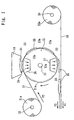
- Fig. 1 is a schematic diagram of the production method of the absorbent body showing the first embodiment of the present invention.
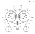
- Fig. 2 is a schematic diagram of the production method of the absorbent body showing the second embodiment of the present invention.
- Fig. 3 is a schematic diagram of the production method of the absorbent body showing the third embodiment of the present invention.
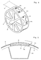
- Fig. 4 is a partial perspective view of the outer surface of the pattern drum of the present invention.
- Fig. 5 is a partial sectional view of the pattern drum showing the state of absorbent material layer formed on the outer surface thereof.
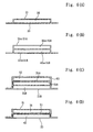
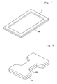
- Fig. 6(A) is a sectional view of the absorbent body produced according to the production method of the present invention.
- Fig. 6(B) is a sectional view of the absorbent body produced according to the production method of the present invention.
- Fig. 6(C) is a sectional view of the absorbent body produced according to the production method of the present invention.
- Fig. 6(D) is a sectional view of the absorbent body produced according to the production method of the present invention.
- Fig. 7 is a perspective view of the absorbent material layer produced according to the production method of the present invention as shown in Fig. 2 .
- Fig. 8 is a perspective view of the absorbent material layer produced according to the production method of the present invention as shown in Fig. 3 .
- Fig. 9 is a perspective view of the absorbent material layer produced according to the production method of the present invention as shown in Fig. 3 .
- Fig. 10 is a perspective view of the absorbent material layer produced according to the production method of the present invention as shown in Fig. 3 .
- Fig. 11 is a perspective view of the absorbent material layer produced according to the production method of the present invention as shown in Fig. 3 .
- Fig. 12 is a perspective view of the absorbent material layer produced according to the production method of the present invention as shown in Fig. 3 .
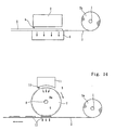
- Fig. 13 is a schematic diagram showing the conventional production method of the absorbent body.
- Fig. 14 is a schematic diagram showing the conventional production method of the absorbent body.
- Fig. 1 is an explanatory diagram showing the first embodiment of the present invention.
- an absorbent body comprising a single absorbent material layer held between two cover sheets is produced.
- a pattern drum 21 is continuously rotated around an axis 22 in the clockwise direction at a certain rotating speed.
- concavities 23 are formed on an outer surface 21a of the pattern drum 21 by predetermined intervals.
- the shape of the concavity 23 is like a sand-glass.
- Mesh 23a are formed at the bottom of the concavity 23 having a screen of 60 meshes (having an opening of 0.246mm) according to the standard of Tyler, U.S.A.
- a pulp supplier 24 for supplying absorbent fibers such as crushed pulps and a supply nozzle 25 for supplying particulate SAP (super-absorbent polymers) are provided above the pattern drum 21 , facing the outer surface 21a thereof.
- the relative position between the supply nozzle 25 and the pulp supplier 24 can be determined appropriately depending on the desired position of supplying the SAP to the crushed pulps.
- the SAP can be made of polyacrylic acid, sodium polyacrylate, polyacrylamide, polyacrylonitrile, polyvinyl alcohol, an additional polymer of maleic anhydride, a polyether, a condensed polymer, a polysaccharide such as starch or cellulose, a protein such as collagen, or the like.
- the SAPs include: a cross-linked compound of sodium polyacrylate, a graft copolymer of starch having sodium polyacrylate or a graft copolymer of cellulose having polyacrylonitrile chains.
- a suction chamber 26 is provided inside the pattern drum 21 , facing the pulp supplier 24 and the supply nozzle 25 . Also, a pressure chamber 27 is provided inside the pattern drum 21 , facing the inside face of the concavity 23 which is moved to the bottom of the pattern drum 21 .
- the suction chamber 26 sucks the air through the mesh 23a of the concavity 23 when the concavity 23 is moved to the top position.
- the pressure chamber 27 pressures the air through the mesh 23a of the concavity 23 when the concavity 23 is moved to the bottom position.
- a cover tissue 31 which becomes a first cover sheet of the absorbent body is drawn from a roll 31a rotating around an axis 32 , wound around the outer surface 21a of the pattern drum 21 and thereafter forwarded to the left as shown in Fig. 1 .
- a carrier tissue 33 which becomes a second cover sheet of the absorbent body is drawn from a roll 33a rotating around an axis 34 and thereafter forwarded continuously to the left at a certain speed as shown in Fig. 1 .
- the carrier tissue 33 is forwarded at the speed of V1 by the force of a conveyor (not shown) being proceeded by the rotation of conveyor rolls provided at the left of the pattern drum 21 .
- the cover tissue 31 is forwarded to the left at the speed of V2 , after going around the outer surface 21a of the pattern drum 21 .
- the speed V1 and V2 are set equal to each other.
- the cover tissue 31 drawn from the roll 31a is laid along (or adapted to) the inner surface of the concavity 23 to form a concave shape and thereafter goes around in the clockwise direction together with the outer surface 21a of the pattern drum 21 .
- the rotating speed of the outer surface 21a of the pattern drum 21 is set almost equal to the forwarding speed V1 of the carrier tissue 33 .
- the speed V3 of drawing out the cover tissue 31 from the roll 31a is set slightly faster than the speed V1 or V2 .
- the pattern drum 21 is rotated in the clockwise direction at a certain speed, and the cover tissue 31 which becomes the first cover sheet of the absorbent body is supplied to the outer surface 21a of the pattern drum 21 .
- the concavity 23 is moved to the top of the pattern drum 21 (i.e., above the suction chamber 26 )
- the sucking force of the suction chamber 26 is applied to the cover tissue 31 through the mesh 23a , and thereby the cover tissue 31 is laid along the surface of the concavity 23 to be deformed in a concave shape.
- the crushed pulps are supplied into the concavity 23 by the pulp supplier 24 and the particulate SAP are supplied into the concavity 23 from the supply nozzle 25 .
- the crushed pulps and the SAP are sucked into the concavity 23 through the mesh 23a and the cover tissue 31 . Consequently, the cover tissue 31 is laid along the inner surface of the mesh 23a in the concavity 23 and thereby the absorbent material layer 35 comprised of a mixture of the crushed pulps and the SAP is formed on the cover tissue 31 as shown in Fig. 5 .
- the shape of this absorbent material layer 35 is the same as the shape of the concavity 23 opening upward.
- the shape of this absorbent material layer 35 can be formed in a sand-glass shape.
- the content of SAP in the absorbent material layer 35 can be arranged such that more of the SAP exist at the position proximate to the cover tissue 31 .
- the carrier tissue 33 is supplied from the roll 33a and is forwarded toward underneath the pattern drum 21 .
- the absorbent material layer 35 and the cover tissue 31 are separated from the concavity 23 by the pressure chamber 27 .
- the absorbent material layer 35 is transferred to the carrier tissue 33 together with the cover tissue 31 .
- an air pressure force is applied to the cover tissue 31 by the pressure chamber 27 to push out the absorbent material layer 35 and the cover tissue 31 from the concavity 23 of the pattern drum 21 .
- the absorbent material layer 35 may be separated from the concavity 23 by applying some other force to the cover tissue 31 in the direction of the carrier tissue 33 .
- a laminated body comprising the carrier tissue 33 and the cover tissue 31 having the absorbent material layers 35 at predetermined intervals between them is produced.
- a cutter such as a rotary cutter, the individual absorbent bodies are produced.
- a hot melt type adhesive can be applied between the absorbent material layer 35 and the cover tissue 31 and/or between the absorbent material layer 35 and the carrier tissue 33 . Also, the cover tissue 31 and the carrier tissue 33 can be adhered with each other at the peripheral of the absorbent material layer 35 .
- the cover tissue 31 is laid on the mesh 23a at the bottom of the concavity 23 of the pattern drum 21 and the crushed pulps and the particulate SAP are supplied thereon, the particulate SAP do not pass into inside of the pattern drum 21 through the screen of mesh 23a , thereby improving the yield ratio of SAP. Also, since the SAP content in the absorbent material layer 35 can be increased, water retention property of the absorbent material layer 35 can be improved. Further, since the SAP are prevented from passing through the screen of mesh 23a , the SAP content in the absorbent material layer 35 can be freely determined and the scattering of the SAP content among the absorbent bodies can be decreased.
- the SAP having a small particle size of 100 mesh or less (which pass through a screen having an opening of 0.147mm) or 200 mesh or less (which pass through a screen having an opening of 0.074mm) can be introduced into the absorbent material layer 35 , liquid absorption speed of the absorbent material layer 35 can be accelerated.
- the SAP having the particle size in the range of 60mesh-200mesh can be introduced into the absorbent material layer 35 in the range of 20%-90% by weight. It is even possible to mix the SAP having smaller particle size than 200mesh into the absorbent material layer 35 .
- Fig. 2 is an explanatory drawing showing the second production method of the absorbent body of the present invention.
- the carrier tissue 33 which becomes the second cover sheet of the absorbent body is drawn from the roll 33a and forwarded continuously at a certain speed V1 .
- Crushed pulps are supplied on the carrier tissue 33 from the pulp supplier 36 . These crushed pulps are sucked to the carrier tissue 33 by the air suction force generated by the suction chamber 37 to form another absorbent material layer 40 in a continuous strip shape on the carrier tissue 33 .
- the absorbent material layer 35 formed at the concavity 23 of the pattern drum 21 is separated from the concavity 23 together with the cover tissue 31 to be laid on the absorbent material layer 40 .
- a double layered absorbent material can be formed between the carrier tissue 33 and the cover tissue 31 . Consequently, a laminated body, comprised of the carrier tissue 33 and cover tissue 31 with the absorbent material having a double layered structure interposed between them, can be produced.
- a cutter such as a rotary cutter in a predetermined dimension
- the absorbent material layer 35 and the cover tissue 31 can be adhered with each other by using a hot melt type adhesive. Also, the absorbent material layer 40 and the carrier tissue 33 can be adhered with each other by using the same type of adhesive. Further, the cover tissue 31 and the carrier tissue 33 can be adhered with each other at the peripheral of the double layered absorbent material formed of the absorbent material layer 35 and the absorbent material layer 40 .
- an absorbent body having an absorbent material layer of a double layer structure can be produced at low cost.
- SAP can be introduced only into the absorbent material layer 35 while introducing no SAP into the absorbent material layer 40 .
- the absorbent material layer 40 also can be formed of the mixture of crushed pulps and SAP by installing another supply nozzle of SAP with the pulp supplier 36 .
- the absorbent material layer 35 is formed of crushed pulps alone while the absorbent material layer 40 is formed of the mixture of crushed pulps and SAP.
- Fig. 3 is an explanatory drawing showing the third production method of the absorbent body of the present invention.
- a first pattern drum 21A and a second pattern drum 21B which have the same structure as that of the pattern drum 21 shown in Figs. 1, 2, 4 and 5, are provided in parallel.
- the first pattern drum 21A is continuously rotating in the clockwise direction
- the second pattern drum 21B is continuously rotating in the counterclockwise direction both at the same speed.
- concavities 23A and concavities 23B are provided on the outer surface of the pattern drum 21A and on the outer surface of the pattern drum 21B respectively.
- the concavity 23A and the concavity 23B may be formed in the same or different shapes.
- a pulp supplier 24A and a supply nozzle 25A for SAP are provided above the pattern drum 21A and a suction chamber 26A is provided inside the pattern drum 21A .
- a pulp supplier 24B and a supply nozzle 25B for SAP are provided above the pattern drum 21B and a suction chamber 26B is provided inside the pattern drum 21B .
- a pressure chamber 27A and a pressure chamber 27B are provided inside the pattern drum 21A and the pattern drum 21B respectively.
- the pressure chambers 27A and 27B are facing each other at the position where the outer surfaces of the pattern drum 21A and the pattern drum 21B are facing each other with the cover tissues 31A and 31B interposed between them.
- the cover tissue 31A is supplied to the outer surface of the first pattern drum 21A and laid along the inside of the concavity 23A .
- Crushed pulps and SAP are supplied from the pulp supplier 24A and supply nozzle 25A respectively into the concavity 23A to form a first absorbent layer 35A comprised of a mixture of crushed pulps and SAP on the cover tissue 31A , the shape of which is the same as that of the concavity 23A .
- the cover tissue 31B is supplied to the outer surface of the second pattern drum 21B . This cover tissue 31B is laid along the inside of the concavity 23B of the second pattern drum 21B .
- Crushed pulps and SAP are supplied from the pulp supplier 24B and the supply nozzle 25B respectively to form a second absorbent material layer 35B , the shape of which is the same as that of the concavity 23B .
- the cover tissue 31A is separated from the concavity 23A together with the absorbent material layer 35A by the pressure chamber 27A
- the cover tissue 31B is separated from the concavity 23B together with the absorbent material layer 35B by the pressure chamber 27B .
- the absorbent material layer 35A and the absorbent material layer 35B are superposed with each other to have a double layer structure, between the cover tissue 31A and the cover tissue 31B , thereby forming a laminated body.
- Such laminated body is cut into pieces in a predetermined dimension to produce the individual absorbent bodies.
- the absorbent material layer 35A and the cover tissue 31A can be adhered each other by using a hot melt type adhesive. Also, the absorbent material layer 35B and the cover tissue 31B can be adhered each other by using the same type of adhesive. It is also possible that the cover tissue 31A and the cover tissue 31B are adhered each other at the peripheral of the absorbent material having a double layer structure formed of the absorbent material layer 35A and the absorbent material layer 35B .
- SAP can be introduced only into either one of the absorbent material layer 35A or the absorbent material layer 35B . Also, it is possible to make the contents and particle sizes of the SAP different between the absorbent material layer 35A and the absorbent material layer 35B .
- Fig. 6(A) shows the absorbent body produced according to the production method shown in Fig. 1 .
- This absorbent body is comprised of the carrier tissue 33 and the cover tissue 31 with the absorbent material layer 35 interposed between them.
- the absorbent material layer 35 is formed of crushed pulps or the mixture of crushed pulps and SAP.
- Fig. 6(B) shows the absorbent body produced according to the production method shown in Fig. 2 or Fig. 3 .
- the absorbent material layer 40 and the absorbent material layer 35 formed in the concavity 23 of the pattern drum 21 are laminated each other and such laminated layers are held between the carrier tissue 33 and the cover tissue 31 .
- the absorbent material layer 35 in a rectangular framework shape is laminated on the absorbent material layer 40 .
- This absorbent material layer 35 in a rectangular framework shape can be formed by forming the concavity 23 of the pattern drum 21 in a rectangular framework shape.
- the absorbent body having the laminated layers shown in Fig. 7 may be used for an excrement absorption sheet for pets, or the like, which can be produced by providing a liquid non-permeable backing sheet at the bottom of the absorbent body and a liquid permeable top sheet on the top of the same.
- the absorbent material layer 40 is formed of crushed pulps alone or the mixture of crushed pulps and SAP, and the absorbent material layer 35 in a rectangular framework shape is formed of the mixture of crushed pulps and SAP. In this case, it is desirable that the absorbent material layer 35 contains more and/or finer SAP than the absorbent material layer 40 .
- the SAP contained in the absorbent material layer 35 preferably have a particle size below 60 mesh, more preferably below 100 mesh, and the SAP content in the absorbent material layer 35 is 20% by weight or more, preferably 30% by weight or more, and more preferably, in the range of 50% -90% by weight.
- the absorption sheet can prevent the urine excrement from leaking outside because the absorbent material layer 35 in a rectangular framework shape absorbs the urine excreted on the absorbent material layer 40 very quickly.
- a colored tissue 51 may be supplied on the absorbent material layer 40 such that the colored tissue 51 is placed between the absorbent material layer 40 and the absorbent material layer 35 as shown in Fig. 6(D) , if the absorbent body is used for the excrement absorption sheet for pets.
- the colored tissue 51 at the area surrounded by the framework shaped absorbent material layer 35 can be seen from outside through the cover tissue 31 and the top sheet.
- the structure of the absorbent body produced according to the production method shown in Fig. 3 is such that the absorbent material layer 35B formed at the concavity 23B is placed on the cover tissue 31B and the absorbent material layer 35A formed at the concavity 23A is laminated on the absorbent material layer 35B and the cover tissue 31A covers the top face thereof, as shown in Fig. 6(B) .
- both the absorbent material layers 35A and 35B can be formed in any desired shapes.
- Fig. 8 and Fig. 9 each show an example of the shape formed by the absorbent material layer 35B and the absorbent material layer 35A in the absorbent body produced according to the production method as shown in Fig. 3 .
- the absorbent material layer 35A and the absorbent material layer 35B are both formed in a sand-glass shape having the same dimensions.
- This combination of absorbent material layers can be made by forming the concavity 23A of the first pattern drum 21A and the concavity 23B of the second pattern drum 21B in the same sand-glass shape and size.
- the absorbent material layer 35A at the upper side is in a sand-glass shape and the absorbent material layer 35B at the lower side is in a rectangular shape.
- the absorbent material layer 35B at the lower side is attached to the absorbent material layer 35A at the upper side only at the central portion in the transversal direction.
- the absorbent bodies having such layers 35A and 35B as shown in Figs. 8 and 9 can be used for a disposable diaper, sanitary napkin, urine absorption pad or the like, which can be produced by providing a liquid non-permeable backing sheet at the bottom of the absorbent body, and a liquid permeable top sheet at the top thereof.
- the absorbent material layer 35A at the upper side is comprised of crushed pulps alone or the mixture of crushed pulps and SAP
- the absorbent material layer 35B at the lower side is comprised of the mixture of the crushed pulps and SAP.
- the absorbent material layer 35B at the lower side contains more and/or finer SAP than the absorbent material layer 35A at the upper side.
- the SAP contained in the absorbent material layer 35B preferably have a particle size below 60 mesh, more preferably below 100 mesh, and the SAP content in the absorbent material layer 35B is 20% by weight or more, preferably 30% by weight or more, and more preferably, in the range of 50% -90% by weight.
- the excrement or secretion liquid introduced to the absorbent material layer 35A at the upper side is moved toward the absorbent material layer 35B at the lower side owing to the strong absorption ability of the more and/or finer SAP contained in the absorbent material layer 35B , before the excrement or secretion liquid spreads all over the absorbent material layer 35A at the upper side. Therefore, the excrement or secretion liquid is prevented from flowing back to the top sheet.
- an absorbent body having such a three layered absorbent material as shown in Fig. 6(C) can be produced. That is, by providing and laminating another absorbent material layer 52 formed on another cover tissue 53 onto the laminated body produced by the production method shown in Fig. 3 , the absorbent body having a three layered absorbent material can be produced.
- the absorbent material layers 35A and 35B have different absorption properties from each other, so that the resulting flat absorbent material layer has partially different absorption property.
- the absorbent material layer 35A is formed in a rectangular shape, while the absorbent material layer 35B is formed of four separate parts, each two of them are lined in parallel in left and right.
- the absorbent material layer 35A is mated with the absorbent material layer 35B within the space provided by the four separate parts of the absorbent material layer 35B to form a flat absorbent material layer.
- the absorbent material layer 35A is formed in a rectangular shape, while the absorbent material layer 35B is formed of two separate absorbent material layers in a rectangular shape lined in parallel.
- the absorbent material layer 35A is mated with the absorbent material layer 35B within the space provided by the two separate rectangular parts of the absorbent material layer 35B to form a flat absorbent material layer.
- the absorbent material layer 35A is formed in a rectangular shape, while the absorbent material layer 35B is formed in a rectangular framework shape.
- the absorbent material layer 35A is mated with the absorbent material layer 35B within the space provided by the rectangular framework shape of the absorbent material layer 35B to form a flat absorbent material layer.
- the absorbent material layer 35B contains crushed pulps alone or the mixture of crushed pulps and SAP
- the absorbent material layer 35A contains the mixture of crushed pulps and more and/or finer SAP than the absorbent material layer 35B
- the particle size of the SAP in the absorbent material layer 35A is for instance less than 60 mesh or less, preferably less than 100 mesh
- the contents of the SAP in the absorbent material layer 35A is 20% by weight or more, preferably 30% by weight or more and more preferably, in the range of 50%- 90% by weight.
- the excrement or secretion liquid is absorbed rapidly by the absorbent material layer 35A placed at the central position and the volume of liquid retention at the absorbent material layer 35A becomes large. Therefore, the spreading of the liquid to the direction of absorbent material layer 35B is slowed and the leakage of the liquid to the side is prevented.
- the absorbent material layer 35A contains crushed pulps alone or the mixture of crushed pulps and SAP
- the absorbent material layer 35B contains the mixture of crushed pulps and more and/or finer SAP than the absorbent material layer 35A .
- the liquid introduced to the absorbent material layer 35A at the central position is moved to the absorbent material layer 35B at the sides and dispersed, the liquid introduced to the absorbent material layer 35A is prevented from flowing back to the top sheet and from leaking outside.
- the flat absorbent material layer shown in Fig. 12 is a modification of the laminated layers composed of absorbent material layers 35 and 40 shown in Fig. 7 , so that the excrement liquid introduced to the absorbent material layer 35A is absorbed by the absorbent material layer 35B formed in a rectangular framework shape.
- the carrier tissue 33 and the cover tissue 31 are used as the cover sheets in the production methods shown in Fig. 1 and Fig. 2
- the cover tissues 31A and 31B are used as the cover sheets in the production method shown in Fig. 3
- air permeable non-woven fabrics or woven fabrics can be used as the cover sheets to produce an absorbent body instead of using the tissues.
- the cover sheet is laid along the concavity of the pattern drum and the absorbent material layer is formed on this cover sheet, the absorbent material layer can be easily separated from the concavity of the pattern drum.
- the particulate SAP is prevented from passing into the pattern drum through the mesh at the bottom of the concavity at the time of introducing the SAP into the absorbent material layer, the yield ratio of SAP at the production of the absorbent body can be improved. Also, it makes possible to introduce very fine SAP and increase the SAP content in the absorbent material layer, so that the liquid retention property and the liquid absorption speed of the absorbent body can be easily improved.
- the absorbent material layers can be easily laminated to each other without providing tissues between the layers. Also, it makes possible to vary the shapes between the absorbent material layers and to mate the absorbent material layers with each other into a single-flat layer.
Description
- Conventional production methods of the absorbent body are explained with reference to Fig. 13 and Fig. 14.
- In the conventional production method of the absorbent body shown in Fig. 13, a
carrier tissue 2 is drawn from aroll 2a which is supported by anaxis 1 and is forwarded continuously. Apulp supplier 3 is provided above thecarrier tissue 2 which is forwarded continuously. Crushed pulps are supplied from thepulp supplier 3 to be poured on thecarrier tissue 2. A supply nozzle 4 for supplying particulate SAP (super-absorbent polymers) is provided above thecarrier tissue 2 and supplies the SAP on thecarrier tissue 2 which is forwarded continuously. - A
suction chamber 6 is provided in the opposite side of thepulp supplier 3 and the supply nozzle 4 with thecarrier tissue 2 interposed. Crushed pulps and the SAP are sucked by thesuction chamber 6 to form a strip of an absorbent material layer 5 comprised of a mixture of crushed pulps and SAP on thecarrier tissue 2. - In a speedy production, crushed pulps and SAP are continuously supplied onto the
carrier tissue 2 to form a strip of an absorbent material layer 5. Thereafter, a cover tissue (not shown) is supplied onto the strip of the absorbent material layer 5 to form a laminated body comprised of thecarrier tissue 2, a cover tissue and the absorbent material layer 5 interposed between the tissues. Subsequently, both sides of the laminated body are cut by a cutter such as a rotary cutter and thereafter the laminated body is cut into individual absorbent bodies. - In the conventional production method of the absorbent body shown in Fig. 14, the
carrier tissue 2 drawn from theroll 2a are forwarded continuously. Acircular pattern drum 7 is provided above thecarrier tissue 2 which is forwarded continuously. Thepattern drum 7 rotates in the clockwise direction around theaxis 8 at a speed adapted to the running speed of thecarrier tissue 2. -
Concavities 9 are provided on the outer face of thepattern drum 7 at predetermined intervals.Mesh 9a of a predetermined screen dimension is provided at the bottom of theconcavity 9. Theconcavity 9 is formed in a predetermined shape such as the shape of a sand-glass. Apulp supplier 11 is provided above thepattern drum 7, facing the outer surface of thepattern drum 7. Likewise, asupply nozzle 12 for supplying SAP is provided also facing the outer surface of thepattern drum 7. - According to the production method of the absorbent body as shown in Fig. 14, crushed pulps are supplied from the
pulp supplier 11 into theconcavity 9 which is provided on the outer surface of the rotatingpattern drum 7. Also, SAP are supplied from thenozzle 12 into theconcavity 9 in the same manner. - A suction means is provided inside of the
pattern drum 7 facing thepulp supplier 11 and thesupply nozzle 12 for sucking air through the openings of themesh 9a provided at the bottom of theconcavity 9. The crushed pulps and the particulate SAP are sucked to be placed onto theconcavity 9 thereby forming theabsorbent material layer 13 having the same shape as that of theconcavity 9. - At the time the
concavity 9 faces thecarrier tissue 2 in the course of the rotation of thepattern drum 7, another suction means provided below thecarrier tissue 2 sucks air through thecarrier tissue 2. By this suction, theabsorbent material layer 13 is transferred onto thecarrier tissue 2. Subsequently, a cover tissue (not shown) is laid along thecarrier tissue 2 and theabsorbent material layer 13, thereby forming a laminated body comprised of thecarrier tissue 2, the cover tissue and theabsorbent material layer 13 interposed between the tissues. Thereafter, thecarrier tissue 2 and the cover tissue are cut in accordance with the shape of theabsorbent material layer 13 to produce individual absorbent bodies. - In a high speed production of the absorbent body according to the conventional production method shown in Fig. 13, because the absorbent material layer 5 is formed in a strip shape on the
carrier tissue 2 in a continuous process, a rectangular absorbent body can be easily produced. However, it is almost impossible to produce an absorbent body having a desired shape such as sand-glass shape. Therefore, in order to produce an absorbent body having a desired shape such as sand-glass shape, it is necessary to conduct a trimming process to such laminated body in a press working process. That results in taking many processing steps. - In addition, in order to laminate another absorbent material layer on the absorbent material layer 5 formed by the conventional production method shown in Fig. 13, crushed pulps and SAP need to be sucked by the suction means through the
carrier tissue 2 and the absorbent material layer 5. However, because of the poor air permeability of the laminated layers formed of thecarrier tissue 2 and the absorbent material 5, it is almost impossible to form another absorbent material layer over such laminated body by sucking another crushed pulps or SAP by such suction means. For this reason, in the production of the absorbent body having two absorbent material layers laminated, each of the absorbent material layers needs to be produced separately by the method shown in Fig. 13 and thereafter laminated each other. Therefore, it inevitably takes many production steps to produce an absorbent body having two absorbent material layers therein. - Moreover, in order to cut the above absorbent body having two laminated absorbent material layers therein, another cover tissue needs to be laid over the absorbent material layer at the upper side. Consequently, at least three tissue layers are needed, making the production of the absorbent body costly.
- On the other hand, according to the conventional production method of the absorbent body shown in Fig. 14, the
absorbent material layer 13 can be formed in the same shape as that of theconcavity 9 formed on the outer face of thepattern drum 7. - However, in order to form the
absorbent material layer 13 in the same shape as that of theconcavity 9, crushed pulps and particulate SAP need to be sucked into theconcavity 9 by the suction force through the openings of themesh 9a provided at the bottom of theconcavity 9. In general, the opening size of themesh 9a is 60 meshes (according to the standard of Tyler, U.S.A., the opening size of such mesh is equal to 0.246mm). - However, because of the fineness of the SAP supplied to the
concavity 9, they easily pass into inside of thepattern drum 7 through themesh 9a, thereby rendering the yield ratio of SAP very poor. Owing to the passage of SAP through themesh 9a which results in a poor yield ratio of SAP, it is very difficult to increase the content of SAP in theabsorbent layer 13. Therefore, it is extremely difficult to produce an absorbent layer containing SAP 20% by weight or more. - Further, in order to accelerate the liquid absorption speed of the absorbent material layer, the particle size of SAP to be contained in the absorbent material layer must be formed very small. However, the
mesh 9a having the opening size of 60 meshes can hardly prevent such fine SAP from passing through into the pattern drum7. Therefore, it is almost impossible for themesh 9a to hold the SAP having a small particle size such as 100 mesh or less (which passes through a mesh having an opening size of 0.147mm) at theconcavity 9. - In addition, according to the conventional production method shown in Fig. 14, the
absorbent material layer 13 must be sucked through thecarrier tissue 2 by the suction means provided below thecarrier tissue 2 at the time theconcavity 9 faces thecarrier tissue 2. However, in order to suck the absorbent material layer formed in theconcavity 9 through thecarrier tissue 2, a very strong suction force is needed. Consequently, the facility of the suction means inevitably becomes large, making the production cost very high. - Further, according to the conventional production method as shown in Fig. 14, it is very difficult to produce an absorbent body having two absorbent material layers laminated each other therein. Because sucking another absorbent material layer to place it on the absorbent body through the
carrier tissue 2 and theabsorbent material layer 13 by a suction means is almost impossible owing to the poor air permeability of the layers. Therefore, in order to produce an absorbent body having two absorbent material layers laminated therein, each of the absorbent material layer must be produced separately and thereafter laminated each other like in the production method shown in Fig. 13. Consequently, the number of steps of producing the absorbent body having two absorbent material layers laminated with each other therein is inevitably increased. - Also, similar to the production method shown in Fig. 13, in order to cut the above absorbent body having two laminated absorbent material layers therein, another cover tissue needs to be laid over the absorbent material layer at the upper side. As a result, at least three tissue layers become necessary, making the production of the absorbent body costly.
- DE 1510427 discloses apparatus which partly overcomes the above problems, by using suction on the drum, but provides no means of discharging the cavity and is limited to producing two articles per drum rotation.
- It is an object of the present invention to provide a production method for an absorbent body which can solve above problems by easily transferring the absorbent material layer formed in the concavity of the pattern drum onto the cover sheet without using a large scaled suction means of the conventional technology.
- It is a further object of the present invention to improve the yield ratio of SAP to be contained in the absorbent material layer, thereby achieving the formation of an absorbent body containing an increased amount of SAP or fine SAP.
- It is a further object of the present invention to provide a production method of an absorbent body which can laminate a plurality of absorbent material layers without using a cover sheet between the laminated absorbent material layers.
- It is a further object of the present invention to produce an absorbent body by laminating a plurality of absorbent material layers wherein each layer may have different shapes, different SAP contents or the SAP having different particle sizes.
- In order to achieve the above objects, the present invention provides the production method for an absorbent body, the method comprising the steps of supplying a first cover sheet on an outer surface of a rotating pattern drum, said pattern drum being provided with a concavity of a predetermined shape on the outer surface thereof; adapting the first cover sheet to the shape of the concavity and supplying an absorbent material into the concavity to form an absorbent material layer adapted to the shape of the concavity on the first cover sheet; supplying a second cover sheet toward the outer surface of the pattern drum; and separating the first cover sheet together with the absorbent material layer from the outer surface of the pattern drum and superposing the first cover sheet together with the absorbent material layer on the second cover sheet to produce an absorbent body comprised of the first cover sheet, the second cover sheet and the absorbent material layer interposed between the first cover sheet and the second cover sheet, characterised in that the bottom of the concavity is formed as a mesh, a suction means is provided inside of the pattern drum for sucking air through the mesh to adapt the first cover sheet to the shape of the concavity and for sucking air through the mesh and the first cover sheet to form the absorbent material layer on the first cover sheet, and a pressure means is provided inside of the pattern drum for pressuring air through the mesh to separate the first cover sheet together with the absorbent material layer from the outer surface of the pattern drum.
- In this production method, it is also possible that another absorbent material layer is formed on the second cover sheet, and the absorbent material layer formed on the first cover sheet is superposed on the absorbent material layer formed on the second cover sheet, between the first cover sheet and the second cover sheet.
- Another aspect of the present invention provides a production method for an absorbent body, the method comprising the steps of: supplying a first cover sheet on the outer surface of the first rotating pattern drum, said first pattern drum being provided with a first concavity formed in a predetermined shape on the outer surface thereof; adapting the first cover sheet to the shape of the first concavity and supplying an absorbent material into the first concavity to form a first absorbent material layer adapted to the shape of the first concavity on the first cover sheet; supplying a second cover sheet on the outer surface of the second rotating pattern drum, said second pattern drum being provided with a second concavity formed in a predetermined shape on the outer surface thereof; adapting the second cover sheet to the shape of the second concavity and supplying an absorbent material into the second concavity to form a second absorbent material layer adapted to the shape of the second concavity on the second cover sheet; and separating the first cover sheet together with the first absorbent material layer from the outer surface of the first pattern drum and separating the second cover sheet together with the second absorbent material layer from the outer surface of the second pattern drum and superposing the first cover sheet together with the first absorbent material layer on the second cover sheet together with the second absorbent material layer to produce an absorbent body comprised of the first cover sheet, the second cover sheet and the first and second absorbent material layers interposed between the first cover sheet and the second cover sheet, characterized in that each bottom of the first and second concavities is formed as a mesh, first and second suction means are provided inside of the first and second pattern drums, respectively, for sucking air through the meshes to adapt the first and second cover sheets to the shapes of the first and second concavities and for sucking air through the meshes and the first and second cover sheets to form the first and second absorbent material layers on the first and second cover sheets, and first and second pressure means are provided inside of the first and second pattern drums, respectively, for pressuring air through the meshes to separate the first and second cover sheets together with the first and second absorbent material layers from the outer surfaces of the first and second pattern drums.
- Embodiments of the present invention will now be described, by way of example only, with reference to the accompanying diagrammatic drawings, in which:
- Fig. 1 is a schematic diagram of the production method of the absorbent body showing the first embodiment of the present invention.
- Fig. 2 is a schematic diagram of the production method of the absorbent body showing the second embodiment of the present invention.
- Fig. 3 is a schematic diagram of the production method of the absorbent body showing the third embodiment of the present invention.
- Fig. 4 is a partial perspective view of the outer surface of the pattern drum of the present invention.
- Fig. 5 is a partial sectional view of the pattern drum showing the state of absorbent material layer formed on the outer surface thereof.
- Fig. 6(A) is a sectional view of the absorbent body produced according to the production method of the present invention.
- Fig. 6(B) is a sectional view of the absorbent body produced according to the production method of the present invention.
- Fig. 6(C) is a sectional view of the absorbent body produced according to the production method of the present invention.
- . Fig. 6(D) is a sectional view of the absorbent body produced according to the production method of the present invention.
- Fig. 7 is a perspective view of the absorbent material layer produced according to the production method of the present invention as shown in Fig. 2.
- Fig. 8 is a perspective view of the absorbent material layer produced according to the production method of the present invention as shown in Fig. 3.
- Fig. 9 is a perspective view of the absorbent material layer produced according to the production method of the present invention as shown in Fig. 3.
- Fig. 10 is a perspective view of the absorbent material layer produced according to the production method of the present invention as shown in Fig. 3.
- Fig. 11 is a perspective view of the absorbent material layer produced according to the production method of the present invention as shown in Fig. 3.
- Fig. 12 is a perspective view of the absorbent material layer produced according to the production method of the present invention as shown in Fig. 3.
- Fig. 13 is a schematic diagram showing the conventional production method of the absorbent body.
- Fig. 14 is a schematic diagram showing the conventional production method of the absorbent body.
- Fig. 1 is an explanatory diagram showing the first embodiment of the present invention.
- According to the production method of the absorbent body shown in Fig. 1, an absorbent body comprising a single absorbent material layer held between two cover sheets is produced.
- A
pattern drum 21 is continuously rotated around anaxis 22 in the clockwise direction at a certain rotating speed. As shown in Fig. 4,concavities 23 are formed on anouter surface 21a of thepattern drum 21 by predetermined intervals. The shape of theconcavity 23 is like a sand-glass.Mesh 23a are formed at the bottom of theconcavity 23 having a screen of 60 meshes (having an opening of 0.246mm) according to the standard of Tyler, U.S.A. - As shown in Fig. 1, a
pulp supplier 24 for supplying absorbent fibers such as crushed pulps and asupply nozzle 25 for supplying particulate SAP (super-absorbent polymers) are provided above thepattern drum 21, facing theouter surface 21a thereof. The relative position between thesupply nozzle 25 and thepulp supplier 24 can be determined appropriately depending on the desired position of supplying the SAP to the crushed pulps. - The SAP can be made of polyacrylic acid, sodium polyacrylate, polyacrylamide, polyacrylonitrile, polyvinyl alcohol, an additional polymer of maleic anhydride, a polyether, a condensed polymer, a polysaccharide such as starch or cellulose, a protein such as collagen, or the like. Examples of the SAPs include: a cross-linked compound of sodium polyacrylate, a graft copolymer of starch having sodium polyacrylate or a graft copolymer of cellulose having polyacrylonitrile chains.
- A
suction chamber 26 is provided inside thepattern drum 21, facing thepulp supplier 24 and thesupply nozzle 25. Also, apressure chamber 27 is provided inside thepattern drum 21, facing the inside face of theconcavity 23 which is moved to the bottom of thepattern drum 21. Thesuction chamber 26 sucks the air through themesh 23a of theconcavity 23 when theconcavity 23 is moved to the top position. Thepressure chamber 27 pressures the air through themesh 23a of theconcavity 23 when theconcavity 23 is moved to the bottom position. - A
cover tissue 31 which becomes a first cover sheet of the absorbent body is drawn from aroll 31a rotating around anaxis 32, wound around theouter surface 21a of thepattern drum 21 and thereafter forwarded to the left as shown in Fig. 1. Acarrier tissue 33 which becomes a second cover sheet of the absorbent body is drawn from aroll 33a rotating around anaxis 34 and thereafter forwarded continuously to the left at a certain speed as shown in Fig. 1. - The
carrier tissue 33 is forwarded at the speed of V1 by the force of a conveyor (not shown) being proceeded by the rotation of conveyor rolls provided at the left of thepattern drum 21. Thecover tissue 31 is forwarded to the left at the speed of V2, after going around theouter surface 21a of thepattern drum 21. The speed V1 and V2 are set equal to each other. - As shown in Fig. 5, the
cover tissue 31 drawn from theroll 31a is laid along (or adapted to) the inner surface of theconcavity 23 to form a concave shape and thereafter goes around in the clockwise direction together with theouter surface 21a of thepattern drum 21. The rotating speed of theouter surface 21a of thepattern drum 21 is set almost equal to the forwarding speed V1 of thecarrier tissue 33. However, since thecover tissue 31 is laid along the inner surface of theconcavity 23, the speed V3 of drawing out thecover tissue 31 from theroll 31a is set slightly faster than the speed V1 or V2. - Next, the production method of the absorbent body shown in Fig. 1 is explained in detail.
- The
pattern drum 21 is rotated in the clockwise direction at a certain speed, and thecover tissue 31 which becomes the first cover sheet of the absorbent body is supplied to theouter surface 21a of thepattern drum 21. When theconcavity 23 is moved to the top of the pattern drum 21 (i.e., above the suction chamber 26), the sucking force of thesuction chamber 26 is applied to thecover tissue 31 through themesh 23a, and thereby thecover tissue 31 is laid along the surface of theconcavity 23 to be deformed in a concave shape. - At this timing, the crushed pulps are supplied into the
concavity 23 by thepulp supplier 24 and the particulate SAP are supplied into theconcavity 23 from thesupply nozzle 25. The crushed pulps and the SAP are sucked into theconcavity 23 through themesh 23a and thecover tissue 31. Consequently, thecover tissue 31 is laid along the inner surface of themesh 23a in theconcavity 23 and thereby theabsorbent material layer 35 comprised of a mixture of the crushed pulps and the SAP is formed on thecover tissue 31 as shown in Fig. 5. The shape of thisabsorbent material layer 35 is the same as the shape of theconcavity 23 opening upward. Thus, in the case of using thepattern drum 21 shown in Fig. 4, the shape of thisabsorbent material layer 35 can be formed in a sand-glass shape. By setting up the relative position of thesupply nozzle 25 and thepulp supplier 24 as shown in Fig. 1, the content of SAP in theabsorbent material layer 35 can be arranged such that more of the SAP exist at the position proximate to thecover tissue 31. - On the other hand, the
carrier tissue 33 is supplied from theroll 33a and is forwarded toward underneath thepattern drum 21. When theconcavity 23 is moved to the bottom of thepattern drum 21 and faced thecarrier tissue 33, theabsorbent material layer 35 and thecover tissue 31 are separated from theconcavity 23 by thepressure chamber 27. Thus theabsorbent material layer 35 is transferred to thecarrier tissue 33 together with thecover tissue 31. In this process, an air pressure force is applied to thecover tissue 31 by thepressure chamber 27 to push out theabsorbent material layer 35 and thecover tissue 31 from theconcavity 23 of thepattern drum 21. Incidentally, although it is preferable to push out theabsorbent material layer 35 and thecover tissue 31 by thepressure chamber 27, theabsorbent material layer 35 may be separated from theconcavity 23 by applying some other force to thecover tissue 31 in the direction of thecarrier tissue 33. - As a result, a laminated body comprising the
carrier tissue 33 and thecover tissue 31 having the absorbent material layers 35 at predetermined intervals between them is produced. By cutting this laminated body in a predetermined dimension at a position between adjacent absorbent material layers 35 by a cutter such as a rotary cutter, the individual absorbent bodies are produced. - In the production of this laminated body (absorbent body), a hot melt type adhesive can be applied between the
absorbent material layer 35 and thecover tissue 31 and/or between theabsorbent material layer 35 and thecarrier tissue 33. Also, thecover tissue 31 and thecarrier tissue 33 can be adhered with each other at the peripheral of theabsorbent material layer 35. - According to the production method described above, because the
cover tissue 31 is laid on themesh 23a at the bottom of theconcavity 23 of thepattern drum 21 and the crushed pulps and the particulate SAP are supplied thereon, the particulate SAP do not pass into inside of thepattern drum 21 through the screen ofmesh 23a, thereby improving the yield ratio of SAP. Also, since the SAP content in theabsorbent material layer 35 can be increased, water retention property of theabsorbent material layer 35 can be improved. Further, since the SAP are prevented from passing through the screen ofmesh 23a, the SAP content in theabsorbent material layer 35 can be freely determined and the scattering of the SAP content among the absorbent bodies can be decreased. Moreover, since the SAP having a small particle size of 100 mesh or less (which pass through a screen having an opening of 0.147mm) or 200 mesh or less (which pass through a screen having an opening of 0.074mm) can be introduced into theabsorbent material layer 35, liquid absorption speed of theabsorbent material layer 35 can be accelerated. - According to the production method of the present invention, the SAP having the particle size in the range of 60mesh-200mesh can be introduced into the
absorbent material layer 35 in the range of 20%-90% by weight. It is even possible to mix the SAP having smaller particle size than 200mesh into theabsorbent material layer 35. - In the production method shown in Fig. 1, it is possible to supply only crushed pulps without supplying SAP to form the
absorbent material layer 35. Even in this case, since theabsorbent material layer 35 can be separated from theconcavity 23 together with thecover tissue 31 laid along theconcavity 23, theabsorbent material layer 35 can be easily removed from theconcavity 23. - Fig. 2 is an explanatory drawing showing the second production method of the absorbent body of the present invention.
- In the production method shown in Fig. 2, another
pulp supplier 36 is provided above thecarrier tissue 33 which is drawn from theroll 33a to become the second cover sheet. Underneath thepulp supplier 36, anothersuction chamber 37 is provided facing thepulp supplier 36 with thecarrier tissue 33 interposed between them. Incidentally, hereinafter, the members and means having the same structure as in Fig. 1 are indicated by using the same reference numbers. Therefore, thepattern drum 21, thecover tissue 31 which becomes the first cover sheet of the absorbent body by being supplied to theouter surface 21a of thepattern drum 21, thepulp supplier 24 and thesupply nozzle 25, all shown in Fig. 2, are the same as those shown in Fig. 1. - According to the production method shown in Fig. 2, the
carrier tissue 33 which becomes the second cover sheet of the absorbent body is drawn from theroll 33a and forwarded continuously at a certain speed V1. Crushed pulps are supplied on thecarrier tissue 33 from thepulp supplier 36. These crushed pulps are sucked to thecarrier tissue 33 by the air suction force generated by thesuction chamber 37 to form anotherabsorbent material layer 40 in a continuous strip shape on thecarrier tissue 33. - Like the production method shown in Fig. 1, at the time the
absorbent material layer 40 and thecarrier tissue 33 are reached underneath thepattern drum 21, theabsorbent material layer 35 formed at theconcavity 23 of thepattern drum 21 is separated from theconcavity 23 together with thecover tissue 31 to be laid on theabsorbent material layer 40. By this process, a double layered absorbent material can be formed between thecarrier tissue 33 and thecover tissue 31. Consequently, a laminated body, comprised of thecarrier tissue 33 andcover tissue 31 with the absorbent material having a double layered structure interposed between them, can be produced. By cutting this laminated body by a cutter such as a rotary cutter in a predetermined dimension, the individual absorbent bodies are produced. - The
absorbent material layer 35 and thecover tissue 31 can be adhered with each other by using a hot melt type adhesive. Also, theabsorbent material layer 40 and thecarrier tissue 33 can be adhered with each other by using the same type of adhesive. Further, thecover tissue 31 and thecarrier tissue 33 can be adhered with each other at the peripheral of the double layered absorbent material formed of theabsorbent material layer 35 and theabsorbent material layer 40. - According to the production method shown in Fig. 2, since no tissue is necessary between the
absorbent material layer 40 and theabsorbent material layer 35, an absorbent body having an absorbent material layer of a double layer structure can be produced at low cost. - According to the production method shown in Fig. 2, further, SAP can be introduced only into the
absorbent material layer 35 while introducing no SAP into theabsorbent material layer 40. Or else, theabsorbent material layer 40 also can be formed of the mixture of crushed pulps and SAP by installing another supply nozzle of SAP with thepulp supplier 36. In this case, at forming theabsorbent material layer 35 and theabsorbent material layer 40 each from the mixture of crushed pulp and SAP, it is possible to make the contents and particle sizes of the SAP different between theabsorbent material layer 35 and theabsorbent material layer 40. - Alternatively, it is also possible that the
absorbent material layer 35 is formed of crushed pulps alone while theabsorbent material layer 40 is formed of the mixture of crushed pulps and SAP. - Fig. 3 is an explanatory drawing showing the third production method of the absorbent body of the present invention.
- In this production method, a
first pattern drum 21A and asecond pattern drum 21B, which have the same structure as that of thepattern drum 21 shown in Figs. 1, 2, 4 and 5, are provided in parallel. Thefirst pattern drum 21A is continuously rotating in the clockwise direction, and thesecond pattern drum 21B is continuously rotating in the counterclockwise direction both at the same speed. Also similar to thepattern drum 21,concavities 23A andconcavities 23B, the bottoms of which are formed as mesh having a screen of 60 meshes, are provided on the outer surface of thepattern drum 21A and on the outer surface of thepattern drum 21B respectively. Theconcavity 23A and theconcavity 23B may be formed in the same or different shapes. - A
pulp supplier 24A and asupply nozzle 25A for SAP are provided above thepattern drum 21A and asuction chamber 26A is provided inside thepattern drum 21A. Similarly, apulp supplier 24B and asupply nozzle 25B for SAP are provided above thepattern drum 21B and asuction chamber 26B is provided inside thepattern drum 21B. - A
pressure chamber 27A and apressure chamber 27B are provided inside the pattern drum 21A and thepattern drum 21B respectively. Thepressure chambers pattern drum 21B are facing each other with thecover tissues - According to the production method of the absorbent body as shown in Fig. 3, the
cover tissue 31A is supplied to the outer surface of thefirst pattern drum 21A and laid along the inside of theconcavity 23A. Crushed pulps and SAP are supplied from thepulp supplier 24A andsupply nozzle 25A respectively into theconcavity 23A to form a firstabsorbent layer 35A comprised of a mixture of crushed pulps and SAP on thecover tissue 31A, the shape of which is the same as that of theconcavity 23A. Also, thecover tissue 31B is supplied to the outer surface of thesecond pattern drum 21B. Thiscover tissue 31B is laid along the inside of theconcavity 23B of thesecond pattern drum 21B. Crushed pulps and SAP are supplied from thepulp supplier 24B and thesupply nozzle 25B respectively to form a secondabsorbent material layer 35B, the shape of which is the same as that of theconcavity 23B. - At the position where the outer surfaces of the pattern drum 21A and the
pattern drum 21B face each other with thecover tissue cover tissue 31A is separated from theconcavity 23A together with theabsorbent material layer 35A by thepressure chamber 27A, and thecover tissue 31B is separated from theconcavity 23B together with theabsorbent material layer 35B by thepressure chamber 27B. Thereafter, theabsorbent material layer 35A and theabsorbent material layer 35B are superposed with each other to have a double layer structure, between thecover tissue 31A and thecover tissue 31B, thereby forming a laminated body. - Subsequently, such laminated body is cut into pieces in a predetermined dimension to produce the individual absorbent bodies.
- The
absorbent material layer 35A and thecover tissue 31A can be adhered each other by using a hot melt type adhesive. Also, theabsorbent material layer 35B and thecover tissue 31B can be adhered each other by using the same type of adhesive. It is also possible that thecover tissue 31A and thecover tissue 31B are adhered each other at the peripheral of the absorbent material having a double layer structure formed of theabsorbent material layer 35A and theabsorbent material layer 35B. - In this production method, since no tissue is necessary between the
absorbent material layer 35A and theabsorbent material layer 35B, an absorbent body having double layered absorbent material structure can be produced at low cost. - Further, SAP can be introduced only into either one of the
absorbent material layer 35A or theabsorbent material layer 35B. Also, it is possible to make the contents and particle sizes of the SAP different between theabsorbent material layer 35A and theabsorbent material layer 35B. - Furthermore, instead of laminating (or superposing) the
absorbent material layers absorbent material layers cover tissues - Next, the structure of the absorbent bodies produced according to the above described production methods is explained.
- Fig. 6(A) shows the absorbent body produced according to the production method shown in Fig. 1. This absorbent body is comprised of the
carrier tissue 33 and thecover tissue 31 with theabsorbent material layer 35 interposed between them. Theabsorbent material layer 35 is formed of crushed pulps or the mixture of crushed pulps and SAP. - Fig. 6(B) shows the absorbent body produced according to the production method shown in Fig. 2 or Fig. 3.
- In the production method shown in Fig. 2, the
absorbent material layer 40 and theabsorbent material layer 35 formed in theconcavity 23 of thepattern drum 21 are laminated each other and such laminated layers are held between thecarrier tissue 33 and thecover tissue 31. - One example of the shape of the laminated layers according to the production method shown in Fig. 2 is illustrated in Fig. 7. The
absorbent material layer 35 in a rectangular framework shape is laminated on theabsorbent material layer 40. Thisabsorbent material layer 35 in a rectangular framework shape can be formed by forming theconcavity 23 of thepattern drum 21 in a rectangular framework shape. - The absorbent body having the laminated layers shown in Fig. 7 may be used for an excrement absorption sheet for pets, or the like, which can be produced by providing a liquid non-permeable backing sheet at the bottom of the absorbent body and a liquid permeable top sheet on the top of the same. The
absorbent material layer 40 is formed of crushed pulps alone or the mixture of crushed pulps and SAP, and theabsorbent material layer 35 in a rectangular framework shape is formed of the mixture of crushed pulps and SAP. In this case, it is desirable that theabsorbent material layer 35 contains more and/or finer SAP than theabsorbent material layer 40. The SAP contained in theabsorbent material layer 35 preferably have a particle size below 60 mesh, more preferably below 100 mesh, and the SAP content in theabsorbent material layer 35 is 20% by weight or more, preferably 30% by weight or more, and more preferably, in the range of 50% -90% by weight. In such structure, the absorption sheet can prevent the urine excrement from leaking outside because theabsorbent material layer 35 in a rectangular framework shape absorbs the urine excreted on theabsorbent material layer 40 very quickly. - Incidentally, although one of the advantages of the production method shown in Fig. 2 is that no tissue is necessary between the
absorbent material layer 40 and theabsorbent material layer 35, it is preferable for the excrement absorption sheet for pets that the area surrounded by theabsorbent material layer 35 is colored. Therefore, in the production method shown in Fig. 2, acolored tissue 51 may be supplied on theabsorbent material layer 40 such that thecolored tissue 51 is placed between theabsorbent material layer 40 and theabsorbent material layer 35 as shown in Fig. 6(D), if the absorbent body is used for the excrement absorption sheet for pets. In this case, thecolored tissue 51 at the area surrounded by the framework shapedabsorbent material layer 35 can be seen from outside through thecover tissue 31 and the top sheet. - The structure of the absorbent body produced according to the production method shown in Fig. 3 is such that the
absorbent material layer 35B formed at theconcavity 23B is placed on thecover tissue 31B and theabsorbent material layer 35A formed at theconcavity 23A is laminated on theabsorbent material layer 35B and thecover tissue 31A covers the top face thereof, as shown in Fig. 6(B). In this production method shown in Fig. 3, both theabsorbent material layers - Fig. 8 and Fig. 9 each show an example of the shape formed by the
absorbent material layer 35B and theabsorbent material layer 35A in the absorbent body produced according to the production method as shown in Fig. 3. - In Fig. 8, the
absorbent material layer 35A and theabsorbent material layer 35B are both formed in a sand-glass shape having the same dimensions. This combination of absorbent material layers can be made by forming theconcavity 23A of thefirst pattern drum 21A and theconcavity 23B of thesecond pattern drum 21B in the same sand-glass shape and size. - In Fig. 9, the
absorbent material layer 35A at the upper side is in a sand-glass shape and theabsorbent material layer 35B at the lower side is in a rectangular shape. Theabsorbent material layer 35B at the lower side is attached to theabsorbent material layer 35A at the upper side only at the central portion in the transversal direction. - The absorbent bodies having
such layers - In those absorbent bodies shown in Figs. 8 and 9, the
absorbent material layer 35A at the upper side is comprised of crushed pulps alone or the mixture of crushed pulps and SAP, and theabsorbent material layer 35B at the lower side is comprised of the mixture of the crushed pulps and SAP. In this case, it is desirable that theabsorbent material layer 35B at the lower side contains more and/or finer SAP than theabsorbent material layer 35A at the upper side. The SAP contained in theabsorbent material layer 35B preferably have a particle size below 60 mesh, more preferably below 100 mesh, and the SAP content in theabsorbent material layer 35B is 20% by weight or more, preferably 30% by weight or more, and more preferably, in the range of 50% -90% by weight. In such structure, the excrement or secretion liquid introduced to theabsorbent material layer 35A at the upper side is moved toward theabsorbent material layer 35B at the lower side owing to the strong absorption ability of the more and/or finer SAP contained in theabsorbent material layer 35B, before the excrement or secretion liquid spreads all over theabsorbent material layer 35A at the upper side. Therefore, the excrement or secretion liquid is prevented from flowing back to the top sheet. In the absorbent body having such structure as shown in Fig. 9, further, since the excrement or secretion liquid introduced to the central portion of theabsorbent material layer 35A at upper side is strongly absorbed by the more and/or finer SAP contained in theabsorbent layer 35B at the lower side, it can prevent the excrement or secretion liquid not only from flowing back to the top sheet but also from leaking to the side of theabsorbent material layer 35A. - Incidentally, by modifying the production method shown in Fig. 3, an absorbent body having such a three layered absorbent material as shown in Fig. 6(C) can be produced. That is, by providing and laminating another
absorbent material layer 52 formed on anothercover tissue 53 onto the laminated body produced by the production method shown in Fig. 3, the absorbent body having a three layered absorbent material can be produced. - Further, in the production method shown in Fig. 3, it is also possible to mate (or combine) the
absorbent material layers cover tissues absorbent material layers - In Fig. 10, the
absorbent material layer 35A is formed in a rectangular shape, while theabsorbent material layer 35B is formed of four separate parts, each two of them are lined in parallel in left and right. Theabsorbent material layer 35A is mated with theabsorbent material layer 35B within the space provided by the four separate parts of theabsorbent material layer 35B to form a flat absorbent material layer. - In Fig. 11, the
absorbent material layer 35A is formed in a rectangular shape, while theabsorbent material layer 35B is formed of two separate absorbent material layers in a rectangular shape lined in parallel. Theabsorbent material layer 35A is mated with theabsorbent material layer 35B within the space provided by the two separate rectangular parts of theabsorbent material layer 35B to form a flat absorbent material layer. - In Fig. 12, the
absorbent material layer 35A is formed in a rectangular shape, while theabsorbent material layer 35B is formed in a rectangular framework shape. Theabsorbent material layer 35A is mated with theabsorbent material layer 35B within the space provided by the rectangular framework shape of theabsorbent material layer 35B to form a flat absorbent material layer. - In the flat absorbent material layer shown in Fig. 10, the
absorbent material layer 35B contains crushed pulps alone or the mixture of crushed pulps and SAP, and theabsorbent material layer 35A contains the mixture of crushed pulps and more and/or finer SAP than theabsorbent material layer 35B. The particle size of the SAP in theabsorbent material layer 35A is for instance less than 60 mesh or less, preferably less than 100 mesh, and the contents of the SAP in theabsorbent material layer 35A is 20% by weight or more, preferably 30% by weight or more and more preferably, in the range of 50%- 90% by weight. In such structure, the excrement or secretion liquid is absorbed rapidly by theabsorbent material layer 35A placed at the central position and the volume of liquid retention at theabsorbent material layer 35A becomes large. Therefore, the spreading of the liquid to the direction ofabsorbent material layer 35B is slowed and the leakage of the liquid to the side is prevented. - In the flat absorbent material layer shown in Fig. 11, the
absorbent material layer 35A contains crushed pulps alone or the mixture of crushed pulps and SAP, and theabsorbent material layer 35B contains the mixture of crushed pulps and more and/or finer SAP than theabsorbent material layer 35A. In such structure, since the liquid introduced to theabsorbent material layer 35A at the central position is moved to theabsorbent material layer 35B at the sides and dispersed, the liquid introduced to theabsorbent material layer 35A is prevented from flowing back to the top sheet and from leaking outside. - The flat absorbent material layer shown in Fig. 12 is a modification of the laminated layers composed of absorbent material layers 35 and 40 shown in Fig. 7, so that the excrement liquid introduced to the
absorbent material layer 35A is absorbed by theabsorbent material layer 35B formed in a rectangular framework shape. - Incidentally, although the
carrier tissue 33 and thecover tissue 31 are used as the cover sheets in the production methods shown in Fig. 1 and Fig. 2, and thecover tissues - As has been described above, according to the production method of the absorbent body of the present invention, since the cover sheet is laid along the concavity of the pattern drum and the absorbent material layer is formed on this cover sheet, the absorbent material layer can be easily separated from the concavity of the pattern drum.
- Further, according to the production method of the absorbent body of the present invention, since the particulate SAP is prevented from passing into the pattern drum through the mesh at the bottom of the concavity at the time of introducing the SAP into the absorbent material layer, the yield ratio of SAP at the production of the absorbent body can be improved. Also, it makes possible to introduce very fine SAP and increase the SAP content in the absorbent material layer, so that the liquid retention property and the liquid absorption speed of the absorbent body can be easily improved.
- Furthermore, according to the production method of the absorbent body of the present invention, the absorbent material layers can be easily laminated to each other without providing tissues between the layers. Also, it makes possible to vary the shapes between the absorbent material layers and to mate the absorbent material layers with each other into a single-flat layer.
- While in the foregoing specification the present invention has been described in relation to preferred embodiments and many details have been set forth for purpose of illustration, it will be apparent to those skilled in the art that the present invention is susceptible to additional embodiments and that certain of the details described herein can be varied considerably without departing from the basic principles of the present invention.
- As used herein, "comprises" and all its grammatical forms specifies the presence of stated features, integers, steps or components, but does not preclude the presence or addition of one or more other features, integers, steps, components or groups thereof.
Claims (15)
- The production method for an absorbent body, the method comprising the steps of:characterised in that the bottom of the concavity (23) is formed as a mesh (23a), a suction means (26) is provided inside of the pattern drum for sucking air through the mesh to adapt the first cover sheet to the shape of the concavity and for sucking air through the mesh and the first cover sheet to form the absorbent material layer on the first cover sheet, andsupplying a first cover sheet (31) on an outer surface (21a) of a rotating pattern drum (21), said pattern drum being provided with a concavity (23) of a predetermined shape on the outer surface thereof;adapting the first cover sheet (31) to the shape of the concavity and supplying an absorbent material into the concavity to form an absorbent material layer adapted to the shape of the concavity on the first cover sheet;supplying a second cover sheet (33) toward the outer surface (21a) of the pattern drum; andseparating the first cover sheet together with the absorbent material layer from the outer surface of the pattern drum and superposing the first cover sheet together with the absorbent material layer on the second cover sheet to produce an absorbent body comprised of the first cover sheet, the second cover sheet and the absorbent material layer interposed between the first cover sheet and the second cover sheet,
a pressure means (27) is provided inside of the pattern drum (21) for pressuring air through the mesh (23a) to separate the first cover sheet together with the absorbent material layer from the outer surface of the pattern drum. - A production method of an absorbent body as described in Claim 1, wherein the absorbent material layer comprises absorbent fibers and particulate super-absorbent polymers.
- A production method of an absorbent body as described in Claim 2, wherein the particle size of the super-absorbent polymers is 60 mesh or less.
- A production method of an absorbent body as described in Claim 2, wherein the content of the super-absorbent polymers in the absorbent material layer is in a range of 20%-90% by weight.
- A production method of an absorbent body as described in Claim 1, wherein another absorbent material layer is formed on the second cover sheet (33), and the absorbent material layer formed on the first cover sheet (31) is superposed on the absorbent material layer formed on the second cover sheet, between the first cover sheet and the second cover sheet.
- A production method for an absorbent body, the method comprising the steps of:characterized in that each bottom of the first and second concavities (23A, 23B) is formed as a mesh, first and second suction means (26A, 26B) are provided inside of the first and second pattern drums, respectively, for sucking air through the meshes to adapt the first and second cover sheets (31A, 31B) to the shapes of the first and second concavities and for sucking air through the meshes and the first and second cover sheets to form the first and second absorbent material layers (35A, 35B) on the first and second cover sheets, andsupplying a first cover sheet (31A) on the outer surface of the first rotating pattern drum (21A), said first pattern drum being provided with a first concavity (23A) formed in a predetermined shape on the outer surface thereof;adapting the first cover sheet (31A) to the shape of the first concavity (23A) and supplying an absorbent material into the first concavity to form a first absorbent material layer (35A) adapted to the shape of the first concavity on the first cover sheet;supplying a second cover sheet (31B) on the outer surface of the second rotating pattern drum (21B), said second pattern drum being provided with a second concavity (23B) formed in a predetermined shape on the outer surface thereof;adapting the second cover sheet (31B) to the shape of the second concavity (23B) and supplying an absorbent material into the second concavity to form a second absorbent material layer (35B) adapted to the shape of the second concavity on the second cover sheet; andseparating the first cover sheet (31A) together with the first absorbent material layer (35A) from the outer surface of the first pattern drum (21A) and separating the second cover sheet (31B) together with the second absorbent material layer (35B) from the outer surface of the second pattern drum (21B) and superposing the first cover sheet together with the first absorbent material layer on the second cover sheet together with the second absorbent material layer to produce an absorbent body comprised of the first cover sheet, the second cover sheet and the first and second absorbent material layers interposed between the first cover sheet and the second cover sheet,
first and second pressure means (27A, 27B) are provided inside of the first and second pattern drums, respectively, for pressuring air through the meshes to separate the first and second cover sheets (31A, 31B) together with the first and second absorbent material layers (35A, 35B) from the outer surfaces of the first and second pattern drums. - A production method of an absorbent body as described in Claim 6, wherein the first absorbent material layer (35A) comprises absorbent fibers alone or absorbent fibers and particulate super-absorbent polymers, and the second absorbent material layer comprises absorbent fibers and particulate super-absorbent polymers.
- A production method of an absorbent body as described in Claim 7, wherein the particle size of the super-absorbent polymers contained in the second absorbent material layer (35B) is smaller than that of the super-absorbent polymers contained in the first absorbent material layer (35A).
- A production method of an absorbent body as described in Claim 8, wherein the particle size of the super-absorbent polymers contained in the second absorbent material layer (35B) is 60 mesh or less.
- A production method of an absorbent body as described in Claim 7, wherein the content of the super-absorbent polymers in the second absorbent material layers (35B) is higher than that of the super-absorbent polymers in the first absorbent material layer (35B).
- A production method of an absorbent body as described in Claim 10, wherein the content of the super-absorbent polymers in the second absorbent material layers (35B) is in a range of 20%-90% by weight.
- A production method of an absorbent body as described in Claim 6, wherein the first absorbent material layer (35A) and the second absorbent material layer (35B) are superposed to each other.
- A production method of an absorbent body as described in Claim 12, wherein the first absorbent material layer and the second absorbent material layer are formed in an identical shape and have different absorption properties from each other.
- A production method of an absorbent body as described in Claim 12, wherein the first absorbent material layer (35A) and the second absorbent material layer (35B) are formed in different shapes.
- A production method of an absorbent body as described in Claim 6, wherein the first absorbent material layer (35A) and the second absorbent material layer (35B) have different shapes and absorption properties from each other and are mated adjacent each other in a horizontal plane.
Applications Claiming Priority (3)
| Application Number | Priority Date | Filing Date | Title |
|---|---|---|---|
| JP12866598 | 1998-05-12 | ||
| JP12866598A JP3909953B2 (en) | 1998-05-12 | 1998-05-12 | Absorber manufacturing method |
| CA002282969A CA2282969C (en) | 1998-05-12 | 1999-09-22 | Production method of absorbent body |
Publications (2)
| Publication Number | Publication Date |
|---|---|
| EP0958801A1 EP0958801A1 (en) | 1999-11-24 |
| EP0958801B1 true EP0958801B1 (en) | 2004-09-08 |
Family
ID=25681210
Family Applications (1)
| Application Number | Title | Priority Date | Filing Date |
|---|---|---|---|
| EP99303652A Expired - Lifetime EP0958801B1 (en) | 1998-05-12 | 1999-05-11 | Production method of absorbent body |
Country Status (5)
| Country | Link |
|---|---|
| US (1) | US6811642B2 (en) |
| EP (1) | EP0958801B1 (en) |
| JP (1) | JP3909953B2 (en) |
| CA (1) | CA2282969C (en) |
| TW (1) | TW397681B (en) |
Cited By (7)
| Publication number | Priority date | Publication date | Assignee | Title |
|---|---|---|---|---|
| US7906065B1 (en) | 2009-08-18 | 2011-03-15 | The Procter & Gamble Company | Method and apparatus for forming a batt of particulate material for use as a component in an absorbent core assembly |
| US7935299B2 (en) | 2005-08-17 | 2011-05-03 | The Procter & Gamble Company | Method and apparatus for forming a batt of particulate material for use as a component in an absorbent core assembly |
| US7981355B2 (en) | 2006-07-20 | 2011-07-19 | Sca Hygiene Products Ab | Mat-forming wheel |
| CN101484105B (en) * | 2006-07-20 | 2012-04-18 | Sca卫生产品股份公司 | An apparatus and method for forming air-laid absorbent cores |
| US8178035B2 (en) | 2006-07-20 | 2012-05-15 | Sca Hygiene Products Ab | Apparatus and method for forming air-laid absorbent cores |
| US8182735B2 (en) | 2006-07-20 | 2012-05-22 | Sca Hygiene Products Ab | Apparatus and method for forming air-laid absorbent cores |
| CN111685935A (en) * | 2019-12-24 | 2020-09-22 | 北京倍舒特妇幼用品有限公司 | High-breathability medical dressing core and production equipment thereof |
Families Citing this family (92)
| Publication number | Priority date | Publication date | Assignee | Title |
|---|---|---|---|---|
| JP3628526B2 (en) * | 1998-10-07 | 2005-03-16 | 花王株式会社 | Molded body manufacturing equipment |
| KR20010016259A (en) * | 2000-11-28 | 2001-03-05 | 이종덕 | The manufacturing device of mense pad |
| US7411110B2 (en) | 2000-12-20 | 2008-08-12 | Kimberly-Clark Worldwide, Inc. | Thin, high capacity absorbent structure and method for producing same |
| JP2004525668A (en) * | 2000-12-20 | 2004-08-26 | キンバリー クラーク ワールドワイド インコーポレイテッド | Thin and high-capacity absorbent structure and method of manufacturing the same |
| US6832905B2 (en) * | 2002-01-16 | 2004-12-21 | Paragon Trade Brands, Inc. | System and method for dry forming absorbent cores |
| JP4070661B2 (en) * | 2002-06-10 | 2008-04-02 | 花王株式会社 | Absorber manufacturing method |
| US7759540B2 (en) | 2002-07-23 | 2010-07-20 | Paragon Trade Brands, Llc | Absorbent articles containing absorbent cores having zoned absorbency and methods of making same |
| ES2428693T3 (en) | 2003-02-12 | 2013-11-08 | The Procter & Gamble Company | Absorbent core for an absorbent article |
| ATE523180T1 (en) | 2003-02-12 | 2011-09-15 | Procter & Gamble | ABSORBENT CORE FOR AN ABSORBENT ARTICLE |
| PL1621166T5 (en) * | 2004-07-28 | 2019-06-28 | The Procter And Gamble Company | Process for producing absorbent core structures |
| DE602004026566D1 (en) | 2004-07-28 | 2010-05-27 | Procter & Gamble | Indirect pressure from AMG |
| US20060264861A1 (en) | 2005-05-20 | 2006-11-23 | Lavon Gary D | Disposable absorbent article having breathable side flaps |
| US7694379B2 (en) | 2005-09-30 | 2010-04-13 | First Quality Retail Services, Llc | Absorbent cleaning pad and method of making same |
| US7962993B2 (en) | 2005-09-30 | 2011-06-21 | First Quality Retail Services, Llc | Surface cleaning pad having zoned absorbency and method of making same |
| US7549853B2 (en) | 2006-11-15 | 2009-06-23 | The Procter & Gamble Company | Apparatus for making air-laid structures |
| US7553146B2 (en) | 2006-11-15 | 2009-06-30 | The Procter & Gamble Company | Apparatus for making air-laid structures |
| US7704441B2 (en) | 2006-11-15 | 2010-04-27 | The Procter & Gamble Company | Method for making air-laid structures |
| ATE537798T1 (en) * | 2006-11-15 | 2012-01-15 | Procter & Gamble | DEVICE FOR PRODUCING AIR-LAID STRUCTURES |
| US9944487B2 (en) | 2007-02-21 | 2018-04-17 | Curt G. Joa, Inc. | Single transfer insert placement method and apparatus |
| US9550306B2 (en) | 2007-02-21 | 2017-01-24 | Curt G. Joa, Inc. | Single transfer insert placement and apparatus with cross-direction insert placement control |
| EP2157956B1 (en) | 2007-06-18 | 2013-07-17 | The Procter and Gamble Company | Disposable absorbent article with sealed absorbent core with substantially continuously distributed absorbent particulate polymer material |
| CA2782533C (en) | 2007-06-18 | 2014-11-25 | The Procter & Gamble Company | Disposable absorbent article with substantially continuously distributed absorbent particulate polymer material and method |
| JP2009291475A (en) * | 2008-06-06 | 2009-12-17 | Zuiko Corp | Absorbent core for sanitary article, and method of manufacturing the same |
| US8206533B2 (en) * | 2008-08-26 | 2012-06-26 | The Procter & Gamble Company | Method and apparatus for making disposable absorbent article with absorbent particulate polymer material and article made therewith |
| US9089453B2 (en) | 2009-12-30 | 2015-07-28 | Curt G. Joa, Inc. | Method for producing absorbent article with stretch film side panel and application of intermittent discrete components of an absorbent article |
| EP2386277B1 (en) * | 2010-04-20 | 2013-11-13 | The Procter and Gamble Company | Apparatus and method for receiving and transferring solid material |
| ITBO20110186A1 (en) * | 2011-04-08 | 2012-10-09 | Gdm Spa | METHOD AND UNIT FOR THE IMPLEMENTATION OF PADDING FOR HYGIENIC ABSORBENT ITEMS. |
| EP2532332B2 (en) | 2011-06-10 | 2017-10-04 | The Procter and Gamble Company | Disposable diaper having reduced attachment between absorbent core and backsheet |
| US9974699B2 (en) | 2011-06-10 | 2018-05-22 | The Procter & Gamble Company | Absorbent core for disposable absorbent articles |
| JP2014515983A (en) | 2011-06-10 | 2014-07-07 | ザ プロクター アンド ギャンブル カンパニー | Disposable diapers |
| CN103607989B (en) | 2011-06-10 | 2017-05-24 | 宝洁公司 | Absorbent structure for absorbent articles |
| EP2532329B1 (en) * | 2011-06-10 | 2018-09-19 | The Procter and Gamble Company | Method and apparatus for making absorbent structures with absorbent material |
| MX341682B (en) | 2011-06-10 | 2016-08-30 | Procter & Gamble | Absorbent structure for absorbent articles. |
| PL2532328T3 (en) | 2011-06-10 | 2014-07-31 | Procter & Gamble | Method and apparatus for making absorbent structures with absorbent material |
| JP5885963B2 (en) * | 2011-08-11 | 2016-03-16 | ユニ・チャーム株式会社 | Disposable wearing items |
| JP6005916B2 (en) * | 2011-08-29 | 2016-10-12 | ユニ・チャーム株式会社 | Method for manufacturing absorbent article |
| US10828204B2 (en) * | 2011-09-08 | 2020-11-10 | Curt G. Joa, Inc. | Apparatus and method for forming absorbent cores |
| PL2628472T3 (en) | 2012-02-20 | 2016-07-29 | Joa Curt G Inc | Method of forming bonds between discrete components of disposable articles |
| US9809414B2 (en) | 2012-04-24 | 2017-11-07 | Curt G. Joa, Inc. | Elastic break brake apparatus and method for minimizing broken elastic rethreading |
| CN104780885A (en) | 2012-11-13 | 2015-07-15 | 宝洁公司 | Absorbent articles with channels and signals |
| US9216118B2 (en) | 2012-12-10 | 2015-12-22 | The Procter & Gamble Company | Absorbent articles with channels and/or pockets |
| EP2740449B1 (en) | 2012-12-10 | 2019-01-23 | The Procter & Gamble Company | Absorbent article with high absorbent material content |
| US8979815B2 (en) | 2012-12-10 | 2015-03-17 | The Procter & Gamble Company | Absorbent articles with channels |
| EP2740450A1 (en) | 2012-12-10 | 2014-06-11 | The Procter & Gamble Company | Absorbent core with high superabsorbent material content |
| PL2740452T3 (en) | 2012-12-10 | 2022-01-31 | The Procter & Gamble Company | Absorbent article with high absorbent material content |
| US9216116B2 (en) | 2012-12-10 | 2015-12-22 | The Procter & Gamble Company | Absorbent articles with channels |
| US10639215B2 (en) | 2012-12-10 | 2020-05-05 | The Procter & Gamble Company | Absorbent articles with channels and/or pockets |
| JP5936560B2 (en) | 2013-01-18 | 2016-06-22 | ユニ・チャーム株式会社 | Absorbent articles |
| ES2655690T3 (en) | 2013-06-14 | 2018-02-21 | The Procter & Gamble Company | Absorbent article and absorbent core formation channels when wet |
| DE102013211945A1 (en) * | 2013-06-24 | 2014-12-24 | Winkler + Dünnebier Gmbh | Process and plant for the production of hygiene articles |
| US9283683B2 (en) | 2013-07-24 | 2016-03-15 | Curt G. Joa, Inc. | Ventilated vacuum commutation structures |
| USD704237S1 (en) | 2013-08-23 | 2014-05-06 | Curt G. Joa, Inc. | Ventilated vacuum commutation structure |
| USD703247S1 (en) | 2013-08-23 | 2014-04-22 | Curt G. Joa, Inc. | Ventilated vacuum commutation structure |
| USD703248S1 (en) | 2013-08-23 | 2014-04-22 | Curt G. Joa, Inc. | Ventilated vacuum commutation structure |
| USD703711S1 (en) | 2013-08-23 | 2014-04-29 | Curt G. Joa, Inc. | Ventilated vacuum communication structure |
| USD703712S1 (en) | 2013-08-23 | 2014-04-29 | Curt G. Joa, Inc. | Ventilated vacuum commutation structure |
| US9789011B2 (en) | 2013-08-27 | 2017-10-17 | The Procter & Gamble Company | Absorbent articles with channels |
| US9987176B2 (en) | 2013-08-27 | 2018-06-05 | The Procter & Gamble Company | Absorbent articles with channels |
| FR3010631A1 (en) | 2013-09-16 | 2015-03-20 | Procter & Gamble | ABSORBENT ARTICLES WITH CHANNELS AND SIGNALS |
| US11207220B2 (en) | 2013-09-16 | 2021-12-28 | The Procter & Gamble Company | Absorbent articles with channels and signals |
| EP2851048B1 (en) | 2013-09-19 | 2018-09-05 | The Procter and Gamble Company | Absorbent cores having material free areas |
| US9289329B1 (en) | 2013-12-05 | 2016-03-22 | Curt G. Joa, Inc. | Method for producing pant type diapers |
| PL2886092T3 (en) | 2013-12-19 | 2017-03-31 | The Procter And Gamble Company | Absorbent cores having channel-forming areas and c-wrap seals |
| US9789009B2 (en) | 2013-12-19 | 2017-10-17 | The Procter & Gamble Company | Absorbent articles having channel-forming areas and wetness indicator |
| EP2905001B1 (en) | 2014-02-11 | 2017-01-04 | The Procter and Gamble Company | Method and apparatus for making an absorbent structure comprising channels |
| EP2949300B1 (en) | 2014-05-27 | 2017-08-02 | The Procter and Gamble Company | Absorbent core with absorbent material pattern |
| EP2949302B1 (en) | 2014-05-27 | 2018-04-18 | The Procter and Gamble Company | Absorbent core with curved channel-forming areas |
| PL2949299T3 (en) | 2014-05-27 | 2018-01-31 | Procter & Gamble | Absorbent core with absorbent material pattern |
| EP2949301B1 (en) | 2014-05-27 | 2018-04-18 | The Procter and Gamble Company | Absorbent core with curved and straight absorbent material areas |
| WO2016149252A1 (en) | 2015-03-16 | 2016-09-22 | The Procter & Gamble Company | Absorbent articles with improved strength |
| DE112016001234T5 (en) | 2015-03-16 | 2017-12-14 | The Procter & Gamble Company | ABSORPTIONS WITH IMPROVED CORE |
| MX2017014428A (en) | 2015-05-12 | 2018-04-10 | Procter & Gamble | Absorbent article with improved core-to-backsheet adhesive. |
| US10543129B2 (en) | 2015-05-29 | 2020-01-28 | The Procter & Gamble Company | Absorbent articles having channels and wetness indicator |
| PL3325387T3 (en) | 2015-07-24 | 2022-06-20 | Curt G. Joa, Inc. | Vacuum commutation apparatus and methods |
| ITUB20154187A1 (en) * | 2015-10-06 | 2016-01-06 | Fameccanica Data Spa | PROCEDURE AND EQUIPMENT FOR THE PRODUCTION OF AN ABSORBENT STRUCTURE |
| EP3167859B1 (en) | 2015-11-16 | 2020-05-06 | The Procter and Gamble Company | Absorbent cores having material free areas |
| EP3238678B1 (en) | 2016-04-29 | 2019-02-27 | The Procter and Gamble Company | Absorbent core with transversal folding lines |
| EP3238676B1 (en) | 2016-04-29 | 2019-01-02 | The Procter and Gamble Company | Absorbent core with profiled distribution of absorbent material |
| WO2019125298A1 (en) | 2017-12-21 | 2019-06-27 | Essity Hygiene And Health Aktiebolag | Absorbent article with a sealing arrangement comprising welding spots and method for manufacturing the absorbent article |
| EP3727260B1 (en) | 2017-12-21 | 2022-11-02 | Essity Hygiene and Health Aktiebolag | Absorbent article with channel sealings and method for manufacturing the absorbent article |
| JP7101248B2 (en) | 2017-12-21 | 2022-07-14 | エシティ・ハイジーン・アンド・ヘルス・アクチエボラグ | Absorbent articles with a hermetically sealed arrangement of constant width and methods of their manufacture. |
| BR112020007571B1 (en) | 2017-12-21 | 2024-02-27 | Essity Hygiene And Health Aktiebolag | ABSORBENT ARTICLE AND ABSORBENT CORE |
| CN111246825A (en) | 2017-12-21 | 2020-06-05 | 易希提卫生与保健公司 | Absorbent article suitable for newborns and method of manufacturing absorbent article |
| ES2962376T3 (en) | 2017-12-21 | 2024-03-18 | Essity Hygiene & Health Ab | Absorbent article with reduced sagging |
| BR112020010011A2 (en) | 2017-12-21 | 2020-11-03 | Essity Hygiene And Health Aktiebolag | absorbent article and absorbent core |
| IT201800002181A1 (en) * | 2018-01-30 | 2019-07-30 | Gdm Spa | APPARATUS AND METHOD OF FORMING AN ABSORBENT PADDING |
| EP3626214B1 (en) * | 2018-09-20 | 2021-08-25 | GDM S.p.A. | Method and unit for forming an absorbent article |
| CN114269305B (en) * | 2019-09-11 | 2023-08-25 | 株式会社瑞光 | Apparatus and method for manufacturing absorber |
| US11737930B2 (en) | 2020-02-27 | 2023-08-29 | Curt G. Joa, Inc. | Configurable single transfer insert placement method and apparatus |
| WO2023009016A1 (en) * | 2021-07-26 | 2023-02-02 | Ghost - Corporate Management, S.A. | Absorbent underpad with drawings obtained by vacuum and its manufacturing process |
| WO2023189981A1 (en) * | 2022-03-28 | 2023-10-05 | 株式会社瑞光 | Method for manufacturing absorbent body |
| CN114886667B (en) * | 2022-04-29 | 2023-07-18 | 雀氏(福建)实业发展有限公司 | Absorption core forming process |
Family Cites Families (9)
| Publication number | Priority date | Publication date | Assignee | Title |
|---|---|---|---|---|
| DE1510427B1 (en) * | 1966-11-02 | 1970-10-08 | Schickedanz Ver Papierwerk | Method and device for the production of molded fiber bodies, in particular absorbent bodies for sanitary napkins |
| US4765780A (en) * | 1986-05-28 | 1988-08-23 | The Procter & Gamble Company | Apparatus for and method of providing a multiplicity of streams of air-entrained fibers |
| IL82511A (en) * | 1986-05-28 | 1992-09-06 | Procter & Gamble | Apparatus for and methods of airlaying fibrous webs having discrete particles therein |
| NZ239726A (en) * | 1990-09-12 | 1994-05-26 | Mcneil Ppc Inc | Absorbent wad of particulate material formed on permeable carrier |
| US5422169A (en) * | 1991-04-12 | 1995-06-06 | The Procter & Gamble Company | Absorbent structures containing specific particle size distributions of superabsorbent hydrogel-forming materials in relatively high concentrations |
| US5226991A (en) * | 1991-10-09 | 1993-07-13 | Mike Svaighert | Method of fabricating airlaid articles and apparatus for performing the method |
| FR2690843A1 (en) * | 1992-05-07 | 1993-11-12 | Peaudouce | Multilayer disposable nappy mfr, - using suction cylinder to take two layers over each other for bonding together |
| US5447677A (en) * | 1993-06-02 | 1995-09-05 | Mcneil-Ppc, Inc. | Apparatus and method for making absorbent products containing a first material dispersed within a second material |
| SE508244C2 (en) * | 1994-02-24 | 1998-09-21 | Moelnlycke Ab | Absorption body and apparatus for making such an absorption body |
-
1998
- 1998-05-12 JP JP12866598A patent/JP3909953B2/en not_active Expired - Lifetime
-
1999
- 1999-05-11 EP EP99303652A patent/EP0958801B1/en not_active Expired - Lifetime
- 1999-05-12 TW TW088107809A patent/TW397681B/en not_active IP Right Cessation
- 1999-09-22 CA CA002282969A patent/CA2282969C/en not_active Expired - Fee Related
-
2002
- 2002-01-03 US US10/038,322 patent/US6811642B2/en not_active Expired - Lifetime
Cited By (13)
| Publication number | Priority date | Publication date | Assignee | Title |
|---|---|---|---|---|
| US7935299B2 (en) | 2005-08-17 | 2011-05-03 | The Procter & Gamble Company | Method and apparatus for forming a batt of particulate material for use as a component in an absorbent core assembly |
| US8182735B2 (en) | 2006-07-20 | 2012-05-22 | Sca Hygiene Products Ab | Apparatus and method for forming air-laid absorbent cores |
| US7981355B2 (en) | 2006-07-20 | 2011-07-19 | Sca Hygiene Products Ab | Mat-forming wheel |
| CN101484105B (en) * | 2006-07-20 | 2012-04-18 | Sca卫生产品股份公司 | An apparatus and method for forming air-laid absorbent cores |
| US8178035B2 (en) | 2006-07-20 | 2012-05-15 | Sca Hygiene Products Ab | Apparatus and method for forming air-laid absorbent cores |
| US8182736B2 (en) | 2006-07-20 | 2012-05-22 | Sca Hygiene Products Ab | Apparatus and method for forming air-laid absorbent cores |
| CN101484104B (en) * | 2006-07-20 | 2012-06-20 | Sca卫生产品股份公司 | An apparatus and method for forming air-laid absorbent cores |
| CN101484103B (en) * | 2006-07-20 | 2012-07-04 | Sca卫生产品股份公司 | An apparatus and method for forming air-laid absorbent cores |
| US7906065B1 (en) | 2009-08-18 | 2011-03-15 | The Procter & Gamble Company | Method and apparatus for forming a batt of particulate material for use as a component in an absorbent core assembly |
| US8221672B2 (en) | 2009-08-18 | 2012-07-17 | The Procter & Gamble Company | Method and apparatus for forming a batt of particulate material for use as a component in an absorbent core assembly |
| US8616867B2 (en) | 2009-08-18 | 2013-12-31 | The Procter & Gamble Company | Method and apparatus for forming a batt of particulate material for use as a component in an absorbent core assembly |
| CN111685935A (en) * | 2019-12-24 | 2020-09-22 | 北京倍舒特妇幼用品有限公司 | High-breathability medical dressing core and production equipment thereof |
| CN111685935B (en) * | 2019-12-24 | 2022-05-13 | 北京倍舒特妇幼用品有限公司 | High-permeability medical dressing core and production equipment thereof |
Also Published As
| Publication number | Publication date |
|---|---|
| CA2282969C (en) | 2005-11-29 |
| US20020056516A1 (en) | 2002-05-16 |
| JP3909953B2 (en) | 2007-04-25 |
| TW397681B (en) | 2000-07-11 |
| JPH11318977A (en) | 1999-11-24 |
| US6811642B2 (en) | 2004-11-02 |
| CA2282969A1 (en) | 2001-03-22 |
| EP0958801A1 (en) | 1999-11-24 |
Similar Documents
| Publication | Publication Date | Title |
|---|---|---|
| EP0958801B1 (en) | Production method of absorbent body | |
| EP0926287B1 (en) | Method for making apertured nonwoven fabric | |
| CN1177574C (en) | Absorbent article having high absorbing area | |
| KR100705186B1 (en) | Method for manufacturing particle deposited body | |
| EP1110528B1 (en) | Absorbent article with multiple high absorbency zones | |
| KR940004020B1 (en) | Method and apparatus for substantially distributing layer of discrete particles | |
| EP0399511B1 (en) | Methods and apparatus for selective placement of fibrous material in formed fibrous articles | |
| AU778617B2 (en) | Method for intermittent application of particulate material | |
| US4027672A (en) | Absorbent article with improved pad and method | |
| AU670369B2 (en) | Apparatus and method for making absorbent products containing a first material dispersed within a second material | |
| EP0598413B1 (en) | Apparatus and method for sealing absorbent materials in an absorbent product | |
| CN101484105B (en) | An apparatus and method for forming air-laid absorbent cores | |
| JPH02107250A (en) | Liquid absorbing body, and method and apparatus for preparing the same | |
| JPH11320742A (en) | Absorbent | |
| JPS62501273A (en) | Method for incorporating powdered organisms into the interior of a fibrous filling and apparatus for its implementation | |
| WO2011040043A1 (en) | Absorbent article and manufacturing apparatus for absorbent article | |
| TWM528734U (en) | Absorbent article | |
| KR100623465B1 (en) | Production method of absorbent body | |
| JP2022106039A (en) | Absorbent article | |
| CN115105301A (en) | Manufacturing method of absorption core body with fast diffusion and accumulation prevention | |
| CN114948450A (en) | Fast-diffusion and anti-accumulation absorption core | |
| JPH01262861A (en) | Absorptive product | |
| CN1137583A (en) | Method for making non-woven fabric paper product |
Legal Events
| Date | Code | Title | Description |
|---|---|---|---|
| PUAI | Public reference made under article 153(3) epc to a published international application that has entered the european phase |
Free format text: ORIGINAL CODE: 0009012 |
|
| AK | Designated contracting states |
Kind code of ref document: A1 Designated state(s): DE FR GB IT |
|
| AX | Request for extension of the european patent |
Free format text: AL;LT;LV;MK;RO;SI |
|
| 17P | Request for examination filed |
Effective date: 20000518 |
|
| AKX | Designation fees paid |
Free format text: DE FR GB IT |
|
| 17Q | First examination report despatched |
Effective date: 20030228 |
|
| GRAP | Despatch of communication of intention to grant a patent |
Free format text: ORIGINAL CODE: EPIDOSNIGR1 |
|
| RBV | Designated contracting states (corrected) |
Designated state(s): DE FR GB IT |
|
| GRAS | Grant fee paid |
Free format text: ORIGINAL CODE: EPIDOSNIGR3 |
|
| GRAA | (expected) grant |
Free format text: ORIGINAL CODE: 0009210 |
|
| AK | Designated contracting states |
Kind code of ref document: B1 Designated state(s): DE FR GB IT |
|
| REG | Reference to a national code |
Ref country code: GB Ref legal event code: FG4D |
|
| RAP2 | Party data changed (patent owner data changed or rights of a patent transferred) |
Owner name: UNICHARM PETCARE CORPORATION |
|
| REF | Corresponds to: |
Ref document number: 69919934 Country of ref document: DE Date of ref document: 20041014 Kind code of ref document: P |
|
| PLAQ | Examination of admissibility of opposition: information related to despatch of communication + time limit deleted |
Free format text: ORIGINAL CODE: EPIDOSDOPE2 |
|
| PLBQ | Unpublished change to opponent data |
Free format text: ORIGINAL CODE: EPIDOS OPPO |
|
| PLAQ | Examination of admissibility of opposition: information related to despatch of communication + time limit deleted |
Free format text: ORIGINAL CODE: EPIDOSDOPE2 |
|
| PLAR | Examination of admissibility of opposition: information related to receipt of reply deleted |
Free format text: ORIGINAL CODE: EPIDOSDOPE4 |
|
| PLBI | Opposition filed |
Free format text: ORIGINAL CODE: 0009260 |
|
| PLBQ | Unpublished change to opponent data |
Free format text: ORIGINAL CODE: EPIDOS OPPO |
|
| PLAX | Notice of opposition and request to file observation + time limit sent |
Free format text: ORIGINAL CODE: EPIDOSNOBS2 |
|
| ET | Fr: translation filed | ||
| 26 | Opposition filed |
Opponent name: THE PROCTER & GAMBLE COMPANY Effective date: 20050606 |
|
| PLAF | Information modified related to communication of a notice of opposition and request to file observations + time limit |
Free format text: ORIGINAL CODE: EPIDOSCOBS2 |
|
| PLBB | Reply of patent proprietor to notice(s) of opposition received |
Free format text: ORIGINAL CODE: EPIDOSNOBS3 |
|
| PLCK | Communication despatched that opposition was rejected |
Free format text: ORIGINAL CODE: EPIDOSNREJ1 |
|
| PLBN | Opposition rejected |
Free format text: ORIGINAL CODE: 0009273 |
|
| STAA | Information on the status of an ep patent application or granted ep patent |
Free format text: STATUS: OPPOSITION REJECTED |
|
| 27O | Opposition rejected |
Effective date: 20080804 |
|
| PLAB | Opposition data, opponent's data or that of the opponent's representative modified |
Free format text: ORIGINAL CODE: 0009299OPPO |
|
| REG | Reference to a national code |
Ref country code: GB Ref legal event code: 732E Free format text: REGISTERED BETWEEN 20101118 AND 20101124 |
|
| REG | Reference to a national code |
Ref country code: FR Ref legal event code: TP |
|
| REG | Reference to a national code |
Ref country code: DE Ref legal event code: R082 Ref document number: 69919934 Country of ref document: DE Representative=s name: STREHL, SCHUEBEL-HOPF & PARTNER, DE |
|
| REG | Reference to a national code |
Ref country code: DE Ref legal event code: R082 Ref document number: 69919934 Country of ref document: DE Representative=s name: STREHL SCHUEBEL-HOPF & PARTNER MBB PATENTANWAE, DE Effective date: 20111207 Ref country code: DE Ref legal event code: R082 Ref document number: 69919934 Country of ref document: DE Representative=s name: PATENTANWAELTE STREHL, SCHUEBEL-HOPF & PARTNER, DE Effective date: 20111207 Ref country code: DE Ref legal event code: R081 Ref document number: 69919934 Country of ref document: DE Owner name: UNI-CHARM CORP., SHIKOKUCHUO-SHI, JP Free format text: FORMER OWNER: UNICHARM PETCARE CORP., TOKYO, JP Effective date: 20111207 Ref country code: DE Ref legal event code: R081 Ref document number: 69919934 Country of ref document: DE Owner name: UNI-CHARM CORP., JP Free format text: FORMER OWNER: UNICHARM PETCARE CORP., TOKYO, JP Effective date: 20111207 |
|
| REG | Reference to a national code |
Ref country code: FR Ref legal event code: PLFP Year of fee payment: 18 |
|
| REG | Reference to a national code |
Ref country code: FR Ref legal event code: PLFP Year of fee payment: 19 |
|
| REG | Reference to a national code |
Ref country code: FR Ref legal event code: PLFP Year of fee payment: 20 |
|
| PGFP | Annual fee paid to national office [announced via postgrant information from national office to epo] |
Ref country code: GB Payment date: 20180329 Year of fee payment: 20 |
|
| PGFP | Annual fee paid to national office [announced via postgrant information from national office to epo] |
Ref country code: DE Payment date: 20180502 Year of fee payment: 20 |
|
| PGFP | Annual fee paid to national office [announced via postgrant information from national office to epo] |
Ref country code: FR Payment date: 20180411 Year of fee payment: 20 Ref country code: IT Payment date: 20180522 Year of fee payment: 20 |
|
| REG | Reference to a national code |
Ref country code: DE Ref legal event code: R071 Ref document number: 69919934 Country of ref document: DE |
|
| REG | Reference to a national code |
Ref country code: GB Ref legal event code: PE20 Expiry date: 20190510 |
|
| PG25 | Lapsed in a contracting state [announced via postgrant information from national office to epo] |
Ref country code: GB Free format text: LAPSE BECAUSE OF EXPIRATION OF PROTECTION Effective date: 20190510 |