EP0961138A1 - Polariser and liquid crystal display element - Google Patents
Polariser and liquid crystal display element Download PDFInfo
- Publication number
- EP0961138A1 EP0961138A1 EP98964580A EP98964580A EP0961138A1 EP 0961138 A1 EP0961138 A1 EP 0961138A1 EP 98964580 A EP98964580 A EP 98964580A EP 98964580 A EP98964580 A EP 98964580A EP 0961138 A1 EP0961138 A1 EP 0961138A1
- Authority
- EP
- European Patent Office
- Prior art keywords
- layer
- polarizer
- birefringent
- plate
- liquid
- Prior art date
- Legal status (The legal status is an assumption and is not a legal conclusion. Google has not performed a legal analysis and makes no representation as to the accuracy of the status listed.)
- Granted
Links
Images


Classifications
-
- G—PHYSICS
- G02—OPTICS
- G02F—OPTICAL DEVICES OR ARRANGEMENTS FOR THE CONTROL OF LIGHT BY MODIFICATION OF THE OPTICAL PROPERTIES OF THE MEDIA OF THE ELEMENTS INVOLVED THEREIN; NON-LINEAR OPTICS; FREQUENCY-CHANGING OF LIGHT; OPTICAL LOGIC ELEMENTS; OPTICAL ANALOGUE/DIGITAL CONVERTERS
- G02F1/00—Devices or arrangements for the control of the intensity, colour, phase, polarisation or direction of light arriving from an independent light source, e.g. switching, gating or modulating; Non-linear optics
- G02F1/01—Devices or arrangements for the control of the intensity, colour, phase, polarisation or direction of light arriving from an independent light source, e.g. switching, gating or modulating; Non-linear optics for the control of the intensity, phase, polarisation or colour
- G02F1/13—Devices or arrangements for the control of the intensity, colour, phase, polarisation or direction of light arriving from an independent light source, e.g. switching, gating or modulating; Non-linear optics for the control of the intensity, phase, polarisation or colour based on liquid crystals, e.g. single liquid crystal display cells
- G02F1/133—Constructional arrangements; Operation of liquid crystal cells; Circuit arrangements
- G02F1/1333—Constructional arrangements; Manufacturing methods
- G02F1/1335—Structural association of cells with optical devices, e.g. polarisers or reflectors
- G02F1/133528—Polarisers
-
- G—PHYSICS
- G02—OPTICS
- G02B—OPTICAL ELEMENTS, SYSTEMS OR APPARATUS
- G02B3/00—Simple or compound lenses
- G02B3/0006—Arrays
- G02B3/0037—Arrays characterized by the distribution or form of lenses
- G02B3/005—Arrays characterized by the distribution or form of lenses arranged along a single direction only, e.g. lenticular sheets
-
- G—PHYSICS
- G02—OPTICS
- G02B—OPTICAL ELEMENTS, SYSTEMS OR APPARATUS
- G02B5/00—Optical elements other than lenses
- G02B5/04—Prisms
- G02B5/045—Prism arrays
-
- G—PHYSICS
- G02—OPTICS
- G02B—OPTICAL ELEMENTS, SYSTEMS OR APPARATUS
- G02B5/00—Optical elements other than lenses
- G02B5/30—Polarising elements
- G02B5/3025—Polarisers, i.e. arrangements capable of producing a definite output polarisation state from an unpolarised input state
-
- G—PHYSICS
- G02—OPTICS
- G02B—OPTICAL ELEMENTS, SYSTEMS OR APPARATUS
- G02B5/00—Optical elements other than lenses
- G02B5/30—Polarising elements
- G02B5/3025—Polarisers, i.e. arrangements capable of producing a definite output polarisation state from an unpolarised input state
- G02B5/3033—Polarisers, i.e. arrangements capable of producing a definite output polarisation state from an unpolarised input state in the form of a thin sheet or foil, e.g. Polaroid
-
- G—PHYSICS
- G02—OPTICS
- G02B—OPTICAL ELEMENTS, SYSTEMS OR APPARATUS
- G02B5/00—Optical elements other than lenses
- G02B5/30—Polarising elements
- G02B5/3083—Birefringent or phase retarding elements
-
- G—PHYSICS
- G02—OPTICS
- G02F—OPTICAL DEVICES OR ARRANGEMENTS FOR THE CONTROL OF LIGHT BY MODIFICATION OF THE OPTICAL PROPERTIES OF THE MEDIA OF THE ELEMENTS INVOLVED THEREIN; NON-LINEAR OPTICS; FREQUENCY-CHANGING OF LIGHT; OPTICAL LOGIC ELEMENTS; OPTICAL ANALOGUE/DIGITAL CONVERTERS
- G02F1/00—Devices or arrangements for the control of the intensity, colour, phase, polarisation or direction of light arriving from an independent light source, e.g. switching, gating or modulating; Non-linear optics
- G02F1/01—Devices or arrangements for the control of the intensity, colour, phase, polarisation or direction of light arriving from an independent light source, e.g. switching, gating or modulating; Non-linear optics for the control of the intensity, phase, polarisation or colour
- G02F1/13—Devices or arrangements for the control of the intensity, colour, phase, polarisation or direction of light arriving from an independent light source, e.g. switching, gating or modulating; Non-linear optics for the control of the intensity, phase, polarisation or colour based on liquid crystals, e.g. single liquid crystal display cells
- G02F1/133—Constructional arrangements; Operation of liquid crystal cells; Circuit arrangements
- G02F1/1333—Constructional arrangements; Manufacturing methods
- G02F1/1335—Structural association of cells with optical devices, e.g. polarisers or reflectors
- G02F1/133528—Polarisers
- G02F1/133536—Reflective polarizers
-
- C—CHEMISTRY; METALLURGY
- C09—DYES; PAINTS; POLISHES; NATURAL RESINS; ADHESIVES; COMPOSITIONS NOT OTHERWISE PROVIDED FOR; APPLICATIONS OF MATERIALS NOT OTHERWISE PROVIDED FOR
- C09K—MATERIALS FOR MISCELLANEOUS APPLICATIONS, NOT PROVIDED FOR ELSEWHERE
- C09K2323/00—Functional layers of liquid crystal optical display excluding electroactive liquid crystal layer characterised by chemical composition
- C09K2323/03—Viewing layer characterised by chemical composition
- C09K2323/031—Polarizer or dye
-
- G—PHYSICS
- G02—OPTICS
- G02B—OPTICAL ELEMENTS, SYSTEMS OR APPARATUS
- G02B3/00—Simple or compound lenses
- G02B3/0006—Arrays
-
- G—PHYSICS
- G02—OPTICS
- G02B—OPTICAL ELEMENTS, SYSTEMS OR APPARATUS
- G02B3/00—Simple or compound lenses
- G02B3/0006—Arrays
- G02B3/0012—Arrays characterised by the manufacturing method
- G02B3/0031—Replication or moulding, e.g. hot embossing, UV-casting, injection moulding
-
- G—PHYSICS
- G02—OPTICS
- G02B—OPTICAL ELEMENTS, SYSTEMS OR APPARATUS
- G02B3/00—Simple or compound lenses
- G02B3/0006—Arrays
- G02B3/0037—Arrays characterized by the distribution or form of lenses
- G02B3/0062—Stacked lens arrays, i.e. refractive surfaces arranged in at least two planes, without structurally separate optical elements in-between
- G02B3/0068—Stacked lens arrays, i.e. refractive surfaces arranged in at least two planes, without structurally separate optical elements in-between arranged in a single integral body or plate, e.g. laminates or hybrid structures with other optical elements
Definitions
- This invention relates to optics, and in particular to light polarizers and a liquid-crystal indicating element based thereon.
- a light polarizer that transforms the natural light into, the polarized light, and a liquid-crystal indicating (LCI) element based thereon are of the necessary elements of the up-to-date devices tor displaying information on liquid crystals (LC), monitoring systems and light blocking.
- the polarizers presently used are films oriented by the uniaxial tension, a polymer film dyed in mass by organic dyes, or iodine compounds.
- a polymer polyvinyl alcohol (PVA) is mainly used [see, e.g. US Patent 5 007 942 (19910].
- Polarizers based on PVA, dyed with iodine have high polarization characteristics and are widely used in production of liquid-crystal indicators for screens, watches, calculators, personal computers, etc.
- polarizer being a substrate whereon applied is molecularly-oriented layer of dichroic dye capable of forming the nematic phase
- Said polarizer has an higher thermal resistance as compared with the polarizer based on PVA, because the polarizer's molecularly-oriented films of the dye has an high thermal stability and can be formed on such stable materials as, e.g., glass.
- a polarizer (Application PCT WO 94/28073(1994)] being a substrate whereon applied is a thin film 0.1-1.5 mcm thick of the molecularly-ordered layer of water-soluble dyes being sulfo-acids or their non-organic salts of azo- and polycyclic compounds, or their mixtures of the general formula (I), have higher polarizing characteristics.
- Chromogene is a chromophore system of a dye
- M - H + Li + , Na + K + , Cs + , NH 4 + which are capable of forming a stable lyotropic liquid-crystal phase, allowing to produce on their basis the stable lyotropic liquid crystals (LLC) and compositions based thereon.
- LLC stable lyotropic liquid crystals
- a polarizer according to application PCT WO 94/28073: on the substrate surface applied are LLC of a dye, and simultaneously the mechanical orientation with subsequent evaporation of a solvent takes place. Thereby on the substrate surface formed is a thin film of the molecularly-ordered dye layer - a polarizing coating (PC) capable of efficiently polarizing the light. But said polarizer has the polarization characteristics which are still insufficient for use in the high-resolution LC-devices.
- PC polarizing coating
- Polarizers ⁇ operating ⁇ owing to other physical phenomena, for example, owing to different reflectances having different polarizations.
- Polarizers of this type are referred to as the reflecting ones; therein used are phenomena of the light polarization both in incidence and reflection of light beams from surface of any dielectric materials at inclined angles close to Brewster angle, and at the normal (perpendicular to the surface) incidence and light reflection from the surface of birefringent materials. In that case an improvement of the polarizing properties is achieved through use of multi-layer design of reflecting polarizers.
- a polarizer comprising at least one birefringent layer having such thickness that therein realized is the interference extremum at output of an optical polarizer at least for one linearly-polarized light component.
- Such polarizer includes interleaved layers of two transparent (non-absorbing in the operating wavelength range) polymer materials, among which at least one of them is the birefringent one. Birefringence in said polymer material is formed when a film manufactured of such material is drawn in the same direction 2-10 times.
- the other layer of polymer material, interleaved in layers with the birefringent layer, is the optically isotropic one.
- the ordinary refraction index of the birefringent layer is equal to the refraction index of the optically isotropic layer.
- the ordinary (small) refraction index of the birefringent layer is selected to be essentially equal to the refraction index of the optically isotropic polymer layer, i.e. there is no difference (abrupt changes) of the refraction indices at boundaries of the birefringent and optically isotropic polymer layers. Therefore, the other linearly-polarized component of the incident non-polarized light, to which component the ordinary (small) refraction index of the birefringent layer corresponds, passes through the multi-layer optical polarizer completely, without any reflections.
- the polarizer known from application PCT WO 95/17691 is a combined one and further comprises a dichroic polarizer having a weak absorption and dichroism, being the optically positioned with a reflecting optical polarizer.
- the role played by the additional dichroic polarizer, the transmission axis of which is parallel to the transmission axis of the reflecting optical polarizer, is reduced to elimination of the external light reflections when the combined polarizer is operated for the ⁇ translucency ⁇ .
- One of the disadvantages of the known polarizer is a comparatively strong spectral dependence of its optical characteristics, i.e. dependence of the polarizing capacity and the reflection index (and transmittance) on the polarized light wavelength. This disadvantage is caused by the circumstance that refraction indices in the used materials descrease as the polarized light wavelength increases.
- the other disadvantage of the known polarizer is the necessity to use a great number of the interleaving layers, which necessity is caused by the circumstance that the birefringence maximum value (difference between the ordinary and extraordinary refraction indices of a birefringent material) in transparent polymer materials is low and generally does not exceed 0.1-0.2. For this reason the reflection index from the layer boundaries is small, and for the purpose to obtain an high reflection as the whole from an optical polarizer, it is necessary to use a great number (100-600) of layers, application of which layers is an extremely difficult task and requires special precision equipment.
- the second reason of the necessity to use a great number of layers in a polarizer in said reference is as follows. To polarize the light in a wide wavelength range in the multi-layer coating, numerous pairs of interleaving layers or groups of pairs having different thicknesses for ⁇ tuning ⁇ of each pairs' group for the ⁇ own ⁇ wavelength within a wide spectrum range must be available.
- the above-cited polarizers of both the dichroic and interference types are to utilize not more than 50% of the incident light energy.
- the above-mentioned polarizing means consists of two pairs of dielectric layers, one layer of said pair being the birefringent one, the other being the optically isotropic one. Thereby said layers are interconnected by their appropriately moulded surfaces and thereby form a homogeneous array of identical cylindrical microlenses.
- a continuous half-wave birefringent plate Between said pairs of said dielectric layers positioned is a continuous half-wave birefringent plate, the optical axis of which plate is at angle of 45° to the direction of geometric axes of said cylindrical lenses.
- Said means for polarization changing is a sectioned birefringent phase-delaying plate, which is a half-wave or quarter-wave plate, parallel to the polarizer plane, and having the optical axis at angle of 45° to the direction of geometric axes of said cylindrical lenses.
- two outputted pluralities of beams become focused in the sections, or in the sections and intervals between sections of said sectioned birefringent phase-delaying plate, which results in such conversion of the polarization state of at least one plurality of said focused light beams of the same polarization, that all the light beams passed through said phase-delaying polarizers, acquire identical polarizations, and the energy transferred by them become practically equal to the energy of the non-polarized light incident on the polarizer.
- birefringent dielectric layers comprised by said polarizing means and means for changing polarization of at least one plurality of light beams of two linearly-polarized components of the non-polarized light incident on the polarizer, are implemented of polyethyleneterephthalate, or a similar polymer, molecularly oriented in a pre-determined direction.
- a polarizer according to US Patent 5 566 367 (1996), comprising a means for converting the incoming non-polarized light into a plurality of identical light beams, a polarizing means for dividing the non-polarized light beams into the polarized passing and reflected light beams having different polarizations a means for changing polarization of the light beams reflected from the polarizing means, and a reflecting means, which means directs the light beams outputted from the polarizer along essentially the same direction.
- a means dividing the non-polarized light beams into the polarized passing and reflected light beams, having different polarizations includes a pair dielectric surfaces arranged at essentially inclined angles to the light beams axis (at the angles approaching the Brewster angle), and a means for changing polarization includes a half-wave plate positioned between said surfaces.
- a reflecting means includes a pair of dielectric surfaces arranged at essentially inclined angles to the light beams' axis (at the angles greater than the full internal reflection angle).
- This known polarizer has an high energy coefficient of converting the non-polarized light to the polarized one, i.e. practically all the energy of the non-polarized light is converted into the outputted polarized light, this polarizer also has a comparatively flat design.
- the above-mentioned polarizers can be used in various devices for displaying information, in particular for manufacture of liquid-crystal indicating (LCI) elements.
- LCD liquid-crystal indicating
- the most typical LCI element is a device implemented as a flat dish formed by two parallel glass plates, on the internal surfaces of which plates applied are electrodes of an optically transparent conductive material, e.g. tin dioxide. Electrode-bearing surfaces of said plates are subjected to a special treatment providing a pre-determined homogeneous orientation of the LC molecules at the plates' surfaces and in the LC film volume. In case of the homogeneous orientation, big axes of the liquid-crystal molecules at the plates' surface are arranged in parallel to the orientation directions, which directions are usually selected to be mutually perpendicular.
- LC polarization plane rotation angle
- a change of the optical properties is registered in the crossed polarizers usually glued on the external surfaces of a dish [L.K. Vistin, JHCA, 1983, vol. XXVII, iss. 2, p. 141-148].
- the display portions across electrodes of which portions a voltage is not applied, transmit the light and appear to be of a light region, while the display portions under a voltage appear to be dark regions.
- the LC element comprises an additional special layer, dyed with organic, or non-organic dyes and implemented in the form of pattern elements (character-synthesizing and game indicators), or in the form of an array of light filter of RGB or CMY types (matrix screens) that provide an appropriate dyeing of the light passing through a light filter element.
- a conventional polarizer based on PVA is a complex system comprising as much as 10 layers: 1. protective film 6. adhesive layer 2. a weak adhesive 7. second support film 3. first support film 8. an adhesive 4. an adhesive layer 9. silicon layer 5. polarizing film 10. substrate film
- a siliconized film is removed (layers 9 and 10), and in assembling of a LCI element the protective film having a glue (layers 1 and 2) is removed and can be replaced with a protective glass.
- a LCI element As the result, after a LCI element is assembled, it represents a device consisting of more than 20 layers. It should be noted that a damage to even one layers of a polarizer renders it unsuitable for manufacturing of a LCI element [A.E. Perregaux, SPIE, Vol. 307, p. 70-75].
- a solution of a polymer e.g. polyvnyl alcohol, that can comprise iodine or dichroic dye
- the polymer solution is subjected to a shearing force, using, for a example, a doctor blade, that is moved along the plates surface.
- the so formed oriented PVA film comprising iodine or a dichroic dye, can see both as a polarizer and a LC orientant.
- the dish is assembled, filled with LC and sealed.
- the so made polarizer now is inside a cell and thus protected against external mechanical effects [US Patent No. 3 941 901 (1976)].
- More thermally stable and having an higher contrast is a known device [Application for RF patent No. 96107430, B.I. No. 21(1998), p. 84-85], wherein as the polarizers used is a thin film of the molecularly-oriented layer of a dichroic dye capable of forming a stable lyotropic liquid-crystal phase - a polarizing coating (PC).
- a PC can serve both as a polarizer and an array for homogeneous orientation of LC.
- a LC cell is assembled, in the standard way, of the so made plates, a filled with a required liquid crystal and sealed.
- An usual drawback of the devices of such type is a low brightness and an insufficient colour saturation of a produced image.
- One of the reasons of such drawback is use of dichroic light polarizers absorbing to 50-60% of the visible spectrum light, and use of the dyes additionally absorbing a portion of the light stream.
- a greater brightness of a light source is needed, which is connected with an increased energy consumption by a display.
- An increased energy consumption results in losses of the LC displays' advantages as the energy-saving devices as compared with alternative devices for displaying information.
- the objective of the invention is to provide polarizers of various types providing, with a relatively simple design, high polarization characteristics in a wide spectrum region.
- the other objective of the invention consists in providing on the basis of said polarizers a liquid-crystal indicating (LCI) element having an higher brightness and colour saturation of an image.
- LCDI liquid-crystal indicating
- the set objective is to be attained by using, in manufacture of a polarizer and LCI element based thereon, of at left one birefringent anisotropically absorbing layer having at least one refraction index growing as the polarized light wavelength increases.
- the distinguishing features of the invention is at least one birefringent anisotropically absorbing layer having at least one refraction index growing as the polarized light wavelength increases.
- This dependence is referred to as the abnormal dispersion resulting in a significant growth of value of at least one refraction index.
- This in its turn results in a significant growth of the birefringence value which can greatly exceed the similar value for the polymer materials of the prototype (0.2) and reach 0.7-0.8 for the birefringent anisotropically absorbing layer in the claimed polarizer.
- At lest one birefringent anisotropically absorbing layer according to the invention has at least one refraction index directly proroptional with the polarized light wavelength.
- birefringent layer allows to manufacture polarizers of various types, including those of the ⁇ interference type ⁇ , dichroic polarizers and polarizers using over 50% of the energy of the incident light.
- One of the essential features of the claimed polarizer of the ⁇ interference type ⁇ is at least one birefringent layer having a thickness whereby the interference extremum is realized at output of a polarizer for at least one linearly-polarized light component. Thickness of the birefringent layer is selected also depending on the type of a material used for manufacture of the layer. Owing to such great value of birefringence, the necessary number of layers is dramatically diminished as compared with the known polarizers.
- the dependence of the conditions to obtain the interference exrema (maximums and minimums) on the light wavelength is significantly lowered and, in the preferred embodiment is completely eliminated, which provides high polarization characteristics of a polarizer in a wide spectrum region.
- the notions of light and optical mean the electromagnetic radiation of visible, nearer ultraviolet and nearer infrared ranges of wavelengthes, i.e. the range from 250-300 nm to 1000-2000 nm (from 0.25-0.3 to 1-2 mcms).
- the notion of the flat layer is cited exclusively for ready understanding. Without loss of the generality, also meant is a polarizer having layers of different shapes: cylindrical, spherical and other more complex shapes. Further, the proposed polarizer of the ⁇ interference type ⁇ can be embodied as both constructionally single and isolated, and as applied onto various substrates or between substrates.
- Birefringent layers are referred to the layers having at least two different refraction indices: the extraordinary n e for one linearly-polarized light component, and the ordinary n o , for the other orthogonal linearly-polarized light component.
- the optical axes to which axes correspond the extraordinary and ordinary refraction indices are orthogonal and disposed in the layer plane.
- the optical axis, to which the extraordinary refraction index n e corresponds, is emphasized in this or other manner.
- this axis can be the drawing direction of a polymer material layer, or a director in an oriented nematic liquid crystal.
- Such birefringent layer in the sense of crystal optics corresponds to optically uniaxial plate cut out in parallel to the main axis.
- optically positive birefringent layers wherein n e > n o .
- all the inferences also apply to the optically negative birefringent layers, wherein n e ⁇ n o .
- Refraction index n x corresponds to the direction of oscillations in the light wave, the direction parallel to the layer plane and directed along the emphasized in some manner direction X in the layer plane; n y corresponds to direction Y of oscillations in the light wave, also parallel to the layer plane, but perpendicular to the X direction; n x corresponds to direction Z of oscillations in the light wave, perpendicular to the layer plane.
- ratio or refraction indices n x , n y n z can be different.
- At least one birefringent anisotropically absorbing layer in the proposed polarizer can have one, two or as much as three refraction indices that grow as the polarized light wavelength increases.
- a polarizer of the ⁇ interference type ⁇ wherein at least one birefringent anisotropically absorbing layer has at least one retraction index that is directly proportional to the polarized light wavelength.
- d thickness of the birefringent anisotropically absorbing layer
- m the interference order corresponding to the interference maximum condition
- the extraordinary index n e will be directly proportional to the light wavelength, i.e.
- n e A ⁇ (where A is the proportionality coefficient), then the wavelength ⁇ shortens ⁇ , which means that the condition of the interference maximum in this case is satisfied for all wavelengthes, furthermore, for all orders of the interference, i.e. for all values of m. Further, when the same material has another thickness, independence from light wavelengthes can be similarly provided for the interference minimum condition.
- the direct proportionality of the refraction index to the light wavelength is a more strict requirement (condition) than simple growth of the refraction index as the polarized light wavelength increases.
- a polarizer of the ⁇ interference type ⁇ is preferable, in which polarizer at least one birefringent anisotropically absorbing layer has the maximal value of at least one refraction index being not less than 1.9.
- the necessary number of layers does not exceed 10, and the spectrum region having high polarization characteristics widens more than three times as compared with the prototype.
- the optimal is a polarizer of the ⁇ interference type ⁇ , wherein thicknesses of the birefringent anisotropically absorbing layers are selected such that to obtain at output of a polarizer the interference minimum for one linearly-polarized light component and, simultaneously, the interference maximum for other orthogonal linearly-polarized light component.
- the peculiarity of the birefringent layers is the mere fact of existence of at least two different, in respect of their values, refraction indices, for instance, n x and n y , corresponding to X and Y axes disposed in the layer plane.
- the layer thickness and the interference order (m number) can be selected such that at output of a polarizer will be obtained the interference minimum for one linearly-polarized component and, simultaneously, the interference maximum for the other orthogonal linearly-polarized light component.
- the interference minimum can correspond to the ordinary refraction index, whereby the interference maximum would be determined, accordingly, by the extraordinary refraction index.
- the reverse situation is also possible, when the interference minimum would correspond to the extraordinary refraction index, whereby the interference maximum will be determined, accordingly, by the ordinary refraction index.
- a polarizer of the ⁇ interference type ⁇ comprising at least two layers, of which at least one of them is the birefringent anisotropically absorbing layer, and the other layer being the optically isotropic one, whose refraction index coincides with, or is maximally proximate to one of the birefringent layer indices.
- the difference between the other birefringent layer refraction index and the refraction index of the optically isotropic layer exceeds 0.2 and reaches 0.7-0.8.
- one linearly-polarized component of the incident non-polarized light to which component corresponds the extraordinary (greater) refraction index of the birefringent anisotropically absorbing layer, is essentially reflected from a multi-layer polarizer owing to the difference between refraction indices at the layers' boundaries.
- the optical travel difference between the waves reflected from boundaries of the same birefringent anisotropically absorbing layer constitutes an integer of wavelengthes, i.e. the result of their interference will be the interference maximum resulting in mutual intensification of the reflected waves.
- optical thicknesses of the optically isotropic material layers can be both significantly greater than a wavelength, and be of wavelength order.
- the ordinary (small) refraction index of birefringent anisotropically absorbing layers coincide with, or maximally approaches the optically isotropic layer refraction index, i.e. there is no difference (abrupt changes) of refraction indices at the layers' boundaries.
- the other linearly-polarized component of the incident non-polarized light to which component the ordinary (small) refraction index of birefringent anisotropically absorbing layer corresponds, passes through a multi-layer polarizer completely, without any reflections.
- the other version of the invention is a polarizer of the ⁇ interference type ⁇ , comprising at least two different birefringent layers, of which at least one is a birefringent anisotropically absorbing layer, one refraction index of which coincides with, or is maximally proximate to one of the birefringent layer's indices, and the second refraction indices of the birefringent layer and the birefringent anisotropically absorbing layer differ from one another, the difference between the second indices being over 0.2.
- the interference result is influenced by the ratio of intensities, hence by amplitudes of electric fields of the interfering rays. It is known that the minimal intensity values in the interference minimum (equalling zero, in theory) can be obtained in the case of their equality. Therefore, it is reasonable to provide the maximum attainable equalization of amplitudes of the interfering rays for the interference minimum conditions, which ensures the maximal ⁇ blanking ⁇ of rays of the corresponding component of the polarized light. To obtain the optimum result of interference for the interference maximum conditions, the reflection coefficients from each of the layers' boundaries must be increased.
- Selection of techniques for manufacture of a polarizer according to the invention depends on the type of materials used for birefringent anisotropically absorbing layers and other layers, and is not important the essence of the invention.
- the characteristic feature of the invention is the fact that at least one birefringent anisotropically absorbing layer can be formed:
- At least one dichroic anionic dye of general formulas (II-IV) can be selected from the following:
- At least one dichroic cationic dye of general formulas (V-VI) can be selected of the following:
- At least one dichroic dye and/or pigment not containing ionogenic or hydrophilic groups can be selected from the following:
- At least one birefringent anisotropically absorbing layer of a polarizer can further comprise a modifier, in capacity of which modifier, hydrophilic and hydrophobic polymers of various types can be used, including liquid-crystal and hydrophobic polymers of various types, including liquid-crystal and silicon-organic polymers; plasticizers and varnishes, inclusive of silicon-organic varnishes, as well as non-ionogenic surfactants.
- a modifier in capacity of which modifier, hydrophilic and hydrophobic polymers of various types can be used, including liquid-crystal and hydrophobic polymers of various types, including liquid-crystal and silicon-organic polymers; plasticizers and varnishes, inclusive of silicon-organic varnishes, as well as non-ionogenic surfactants.
- Use of a modifier also allows to decrease light scattering, which is possible due to the presence of microdefects in a birefringent anisotropically absorbing layer.
- a birefringent anisotropically absorbing layer in the proposed polarizer can be both solid and liquid.
- the above-mentioned materials can be used for forming a birefringent anisotropically absorbing layer for manufacturing not only a polarizer of the ⁇ interference type ⁇ but also for the below-claimed and based on other physical phenomena polarizers and LCI elements based thereon.
- aqueous, water-organic and organic solutions of appropriate dyes that can be prepared by a gradual increase of concentration of the diluted solutions (e.g. by evaporating or membrane ultrafiltration), or by solving the dry dyes in a relevant solvent (water, a mix of water with alcohols, bipolar aprotic solvents of DMFA or DMSO types, cellosolves, ethylacetate and other water-miscible solvents) up to the necessary concentration.
- a relevant solvent water, a mix of water with alcohols, bipolar aprotic solvents of DMFA or DMSO types, cellosolves, ethylacetate and other water-miscible solvents
- dye solutions having concentration of 1 to 30% are used.
- the mechanical ordering of stable LLC compositioned basing on dyes can be done by action of the forces causing the tension strain on meniscus created in time of the wedging-out detachment of one surface from the other, between which surfaces a LLC layer is distributed, or in time when a shearing force is applied, which can be done simultaneously with application of LLC on the substrate surface.
- Orienting of LLC of the substrate surface under a shearing force can be executed when LLC is applied using a die or doctor blade; the latter can of the blade or cylindrical type.
- Dye solutions (II-VI) can further contain, besides the water-miscible organic solvents, the non-ionogenic surfactants, binders and film-forming reagents, and as such the following can be used: polyvinyl alcohol, polyvinylpyrrolidone, polyacrylic acid and its esthers, polyacrylamide, polyethylene oxide and polyethylene glycols, polypropylene glycol and their copolymers, ethylic and oxypropylic esters of cellulose, sodium salt of carboxymethyl cellulose, etc.
- the dye solutions can comprise hydrotropic additives of the amides series, e.g. dimethylformamide, alkylamides of phosphoric acid, carbamide and its N-substituted derivatives, N-alkylpyrrolidone, dicyanamide, and also their mixtures and mixtures of amides and glycols.
- Dyes (II-VI) can be also used for forming birefringent anisotropically absorbing layers and in combinations with non-organic salts of dichroic anionic dyes of general formula (I).
- One technique consists in a sequential step-wise neutralization of diluted solutions of appropriate carboxylic, phosphonic acids or sulfo-acids of dichroic anionic dyes using different bases, in capacity of which the following can be used: metal hydroxides, aliphatic or heterocyclic amines or hydroxides of tetra-substituted cations of ammonium.
- the used acids of dyes are cleared beforehand from mineral salts, for example they are washed by hydrochloric acid, with subsequent drying at 100°C.
- the other technique consists in heating of solutions ammonium salts of dichroic anionic dyes having a calculated quantity of the relevant base at the temperature not over 60°C, whereat the released ammonia volatiles, and an appropriate mixed salt is formed, wherein one of the cations will be the ammonium cation. Also can be used ordinary reactions of cation exchange using the ion-exchange resins or the membrane technology.
- the third universal technique suitable for preparing asymmetrical salts of dichroic dyes containing organic cations, consists in exchange of various ions using the membrane technology techniques which simultaneously allow to purify the dichroic dye solutions.
- One of the techniques consists in neutralization of the diluted solutions of the respective acidic forms of dichroic anionic dyes using aliphatic or heterocyclic amines or hydroxides of tetrasubstituted ammonium cations containing, as one of substituents, a hydrocarbon radical with 8-10 carbon atoms.
- the used dye acids are beforehand purified of mineral salts, for example they are washed using hydrochloric acid with subsequent drying at 100°C.
- the other technique consists in heating of solutions of ammonium salts of dichroic anionic dyes, having relevant surface-active bases, at the temperature not over 60°C, whereat the released ammonia volatiles, and an appropriate associate is formed. Also can be used ordinary reactions of cation exchange using the ion-exchange resins and the membrane technology.
- the third method suitable to obtain associates of any dichroic dyes comprising ionogenic groups or their mixtures with at least one mole of the surface-active ions, or their mixes consists in exchange of various ions for the surface-active ions.
- the exchange can be done using the membrane technology techniques, which also allow simultaneous purification of associate solutions of dichroic dyes comprising ionogenic groups, or their mixes with at least one mole of surface-active ions, or their mixes, from undesired non-organic and organic impurities.
- polarizing coating from a water-insoluble dichroic dye and/or pigment not containing ionogenic or hydrophilic groups, or their mixes, which, as a rule, are not readily soluble in most organic solvents.
- polarizing coatings on the basis of the vat dyes, anthraquinonic derivatives, perynonic and polycycloquinonic compounds can be essentially carried out by the following methods:
- Formation of the birefringent layer on the substrate surface under action of a shearing force can be implemented by applying the solutions using a die or doctor blade, the latter can be of the knife or cylindrical type.
- birefringent layer magnetic, electromagnetic and electrostatic fields, that can be used in the cases when the application period is not limited, can be utilized, or for manufacture of a polarizing coating diluted solutions are used.
- dyes can be metallized directly on the substrate surface.
- the substrate preliminary applied is (e.g. by the directed deposition) the oriented layer of metal oxides, whereafter the surface is treated by solution of an appropriate dye.
- ultra-thin oriented layers of water-insoluble metal complex dyes especially suitable for manufacturing the interference type of the claimed polarizer, can be produced.
- a more universal technique for obtaining a birefringent layer on the basis of the water-insoluble dichroic dyes and/or pigments consists in preparation of special output forms obtained by dispersion of said dyes to produce anisometric particles not larger than 0.5 mcm, and having the length-diameter ratio not less than 20.
- various surfactants are used for stabilization of such output forms used.
- prepared are highly-concentrated (content of a dichroic dye and/or pigment, or their mixes, being not less than 10%) systems in different solvents, including water, in monomers or melts of polymers. Thereby the so produced systems can exist also in the liquid-crystal state.
- a birefringent anisotropically absorbing layer When such highly-concentrated systems are applied to the substrate surface, with simultaneous orienting action and with subsequent relevant treatment, produced is a birefringent anisotropically absorbing layer.
- a polarizing coating consisting mainly of a dichroic dye and/or pigment.
- thicker (to 5 mcm) polarizing coatings are formed.
- the application method selection is determined also by the type of a substrate, that can be a solid, flat, spherical or cylindrical, transparent or reflecting surface of an organic or non-organic glass, silicate glass bearing a deposited semiconductor layer, silicon plates bearing the deposited aluminium layer.
- birefringent anisotropically absorbing layers the following standard method can be used: application by roller, doctor blade in the form of a rotating cylinder, application with a slit die, and other methods.
- a standard equipment for applying various coatings can be used, for example units of varnish-paint industry, and also printing equipment of various types, inclusive of flexography units.
- the applied layer is dried so that solvents will be eliminated.
- the applied layer is cooled after application.
- Another technique for obtaining birefringent anisotropically absorbing layers is the known technique of photo-orientation of layer, applied in this or other manner, by irradiating the same by the linearly-polarized ultraviolet light.
- extruders can be used, including those having a number of flat dies and allowing to apply at one run several layers of different polymer materials of the required thickness.
- the proposed polarizer of the interference type can be embodied both in the combined form, i.e. operated both for ⁇ reflection ⁇ and ⁇ transmission ⁇ , and for operation only for ⁇ reflection ⁇ .
- the embodiment version is a polarizer comprising at least one light-reflecting layer.
- the light-reflecting layer can be a metallic one.
- Application of the light-reflecting layer also permits to select the optimum, for the interference, reflection factors from the polarizer boundaries.
- the first layer to be applied onto a substrate can be both the light-reflecting layer (a partially or completely reflecting mirror), and a birefringent anisotropically absorbing layer.
- the reflecting layer can be made both of a metal, and in the form of multi-layer dielectric mirrors of interleaving layers of materials having an high and low refraction indices.
- Metallic coatings are sufficiently simply applied, for example, by thermal evaporation in vacuum, but thereby in such coatings, absorption of light takes place, which diminishes transmission (reflection) of a polarizer.
- aluminium (Al), silver (Ag) and other metals can be used.
- TiO 2 , MgO, ZnS, ZnSe, ZrO 2 , cryolite and polymers as the materials having an high refraction index can be used for these coatings, and as the materials having a low refraction index the following can be used: SiO 2 , Al 2 O 3 , CaF 2 , BaF 2 MgF 2 AlN, BN, or polymers.
- the following standard methods can be used, for example, thermal evaporation in vacuum, application in pairs with subsequent thermal treatment, magnetron sputtering.
- any materials transparent in the operating wavelength range can be used, for example quartz, glass, polymer and other.
- a polarizer operating only for ⁇ reflection ⁇ can be applied, along with the materials transparent in the operating wavelength range, for example quartz, glass, polymers, other any materials opaque in the operating wavelength range, for example metals, semiconductor materials, glass ceramic, plastics and other can be used.
- birefringent anisotropically absorbing layer having an unspecified thickness, i.e. the thickness whereat the interference extremum at output of polarizer at least for one linearly-polarized light component is not realized, allows also to create a polarizer of the dichroic type.
- a birefringent anisotropically absorbing layer is the oriented in a certain direction molecularly-ordered dye layer, wherein planes of molecules and the dipole moments lying therein are homogeneously oriented relative to the direction which is determined either by the surface anisotropy, or by the mechanical orientation direction.
- the claimed polarizer is capable of providing polarization not only in the visible portion of spectrum, but also in the UF-region, as well as in the nearer IR-region.
- the birefringent layer can be used as the phase-delaying layers.
- the essential distinguishing feature of a polarizer of the dichroic type according to the invention is the circumstance that at least one birefringent anisotropically absorbing layer is formed of dyes (II-VI) and/or of a water-insoluble dichroic dye and/or pigment not containing ionogenic or hydrophilic groups.
- a birefringent anisotropically absorbing layer When a solution is applied in the LLC state one the substrate surface, with simultaneous orienting action, a birefringent anisotropically absorbing layer can be formed, wherein planes of the dichroic dye molecules' chromophore systems and the optical transition dipole moments lying thereon are oriented relative to the direction that can be determined either by the surface anisotropy, or the action effected by magnetic or electromagnetic fields.
- a molecule of a dichroic dye can be both the hydrophilic (polar) component, and perform the function of the hydrophobic portion of a SUR.
- a surface-active associate in the presence of two ionogenic groups in a dichroic dye molecule, when said dye is condensed with one mole of the surface-active ion, formed is a surface-active associate, wherein the hydrophilic portion is directly associated with the dye molecule.
- One of the peculiarities of the associates based on the dichroic dyes having the surface-active ions is the capability to increase, owing to the solubilization phenomenon, the solubility of the water-insoluble dyes in water and aqueous-organic media, which allows to obtain a polarizer, wherein at least one birefringent anisotropically absorbing layer additionally contains a solubilized dichroic dye.
- the dipole moment of the solubilized dye optical transition can either coincide with the associated dye optical transition dipole moment, or situated at a certain angle thereto. This depends both on the surface-active ion structure, and molar ratio of dye : SUR in an associate.
- the hydrophobic-hydrophilic balance and solubility of the dichroic dye associates containing the ionogenic groups, or mixes thereof, with at least one mole of an organic ion and/or surface-active ions, or their mixes, allows to control both the formation process and type of the LLC phase.
- the molecular ordering degree also depends, in its turn, on the above-described circumstance and, hence, the polarization parameters of the PC formed after a LLC composition is applied on the substrate surface, with subsequent removal of a solvent.
- Absence of ions in the birefringent anisotropically absorbing layer on the basis of a water-insoluble dichroic dye and/or pigment not containing the ionogenic or hydrophilic groups, or mixes thereof, provides high dielectric properties of the claimed polarizer, which results in lowering of the energy consumption, thereby extending service life of the liquid-crystal devices.
- water-insoluble dichroic dyes or pigments for formation of a birefringent anisotropically absorbing layer, apart from a low conductivity provides an high resistance to effects of moisture. Further, manufacture of the claimed polarizer does not require any synthesis of special dyes or pigments, for the commercially avaliable dyes and pigments can be used.
- birefringent anisotropically absorbing layer formed of dyes (II-VI) and/or water-insoluble dichroic dye and/or pigment not containing the ionogenic or hydrophilic groups, or mixes thereof, allows to prodece a thermally stable and lightfast polarizer:
- a polarizer wherein at least one birefringent anisotropically absorbing layer comprises at least two fragments of an unspecified shape, which are different in respect of colour and/or the polarization axis direction
- the following technique can be used: using a printing method (flexo-stenciling, relief or gravure) on a layer, having the homogeneous polarization vector, applied is a pattern in the form of a water-insoluble varnish of the necessary form. After the varnish is hardened, the exposed layer is washed by an appropriate solvent (water, or a mix of water with an organic solvent). Then the other layer is again applied on the substrate, which layer is of a different colour and the polarization vector than the fixed birefringent layer made of said varnish. Then a layer of varnish of the necessary form is applied once again, whereby the previous pattern remains exposed. After hardening and subsequent washing, a polarizing pattern is produced, said pattern having portions of different colours and the polarization vector direction.
- multi-colour polarizing patterns can be applied according to ⁇ roll-to-roll ⁇ technique.
- the reverse transfer technique is also possible: application of a glue layer of a necessary form on the required surface, application of a film bearing the applied thereon birefringent anisotropically absorbing layer on a glue, and detachment.
- a birefringent anisotropically absorbing layer corresponding only to the glue layer form will be removed from the film surface to a required surface.
- dyes (II-VI) and/or water-insoluble dichroic dye and/or pigment not containing the ionogenic or hydrophilic groups, or mixes thereof allows to realize the technique of layer-by-layer application of birefringent anisotropically absorbing layers.
- a polarizer consisting of several applied one upon another birefringent anisotropically absorbing layers, each consisting of several fragments of an unspecified shape that can be different in respect of colour and the polarization vector direction, can be produced.
- next layer of the same dye or of other one can be applied directly on the previous layer, or on the intermediate layer of a transparent material, which can be either colourless or dyed.
- next layer polarization vector direction can be varied in an unspecified manner relative to the direction of axes of polarization of the previous layer.
- the substrate surface, in forming a birefringent anisotropically absorbing layer can be further modified using different sub-layers, including the optically active ones, for example the light-reflecting, in particular, diffusion-reflecting, birefringent or phase-delaying layers.
- the optically active ones for example the light-reflecting, in particular, diffusion-reflecting, birefringent or phase-delaying layers.
- a quarter-wave birefringent plate or film for example of a polyvinyl aclohol or polyethyleneterephthalate are used as the substrate, and when the birefringent anisotropically absorbing layer is applied at angle of 45° to the main optical axis of the substrate, a circular polarizer can be produced (Fig. 5, a and b is the direction of the ordinary and extraordinary rays, respectively, and n is the polarizing layer polarization vector direction).
- polarizers in the form of flexible polarizing films, including self-gluing films, can be obtained.
- glues including polyvinylbutyral
- polarizers for manufacture of the claimed polarizer, different glues, including polyvinylbutyral, can be used for producing various types of laminated structures, for example triplex glasses or multi-layer films, which is of an interest for automotive industry and architecture.
- polarisers of the dichroic type according to the invention apart form a low conductivity, exhibit an high resistance to effects of moisture and an higher dichroic ratio as compared with the polarizer according to application PCT WO 94/28073 (1994).
- the claimed polarizers have homogeneous properties across their area, one of criteria of which properties is different thickness of the birefringent anisotropically absorbing layer, not exceeding 5%.
- birefringent layer having the abnormal dispersion also allows to produce a polarizer that provides conversion of practically entire energy of a non-polarized radiation source into the polarized radiation.
- the proposed polarizer of said type includes:
- Said polarizing means implemented in the form of the focusing optical elements, each consisting of at least one birefringent anisotropically absorbing layer adjacent to at least one optically isotropic layer, is optically registered with said means for polarization changing implemented in the form of a sectioned translucent birefringent plate.
- said polarizer will be referred to as the polarizer based on the transmissive type polarizing means.
- this polarizer is also the use, in said polarizing means, of at least one birefringent anisotropically absorbing layer having at least one refraction index growing as the polarized light wavelength increases.
- Said focusing optical element of the claimed polarizer can be implemented in the form of a zone plate, which in its turn can be implemented in the form of an amplitude zone plate, wherein the even zones comprise at least one birefringent anisotropically absorbing layer adjacent to at least one optical isotropic layer, and the odd zones are manufactured of an optically isotropic material.
- a phase zone plate can serve as the other version of the zone plate of the claimed polarizer.
- a phase zone plate can have at least one refraction index changing at least along one of the directions, inclusive of that along the plate.
- At least one refraction index of a phase zone plate can change in the direction along the plate plane according to a certain rule, including a non-monotonic change.
- the means for changing polarization of the claimed polarizer can also comprise a sectioned translucent birefringent anisotropically absorbing layer having at least one refraction index growing as the polarized light wavelength increases.
- At least one retraction index of at least one birefringent anisotropically absorbing layer in a polarizer based on a polarizing means of the transmissive type can be directly proportional to the polarized light wavelength.
- At least one birefringent anisotropically absorbing layer of the claimed polarizer can have a thickness whereat the interference extremum at output of a polarizer at least for one linearly-polarized light component is realized. Thereby thickness of at least one birefringent anisotropically absorbing layer satisfies the condition of obtaining, at output of an optical polarizer, the interference minimum for one linearly-polarized component of the passing light and the interference maximum for other orthogonal linearly-polarized component of the passing light.
- layers are selected such that refraction index of the optically isotropic layer will coincide with, or be maximally proximate to one of indices of the birefringent layer.
- a polarizer characterized in that the means for changing polarization is implemented in the form of a sectioned translucent half-wave birefringent plate or a layer having sections disposed in focuses or outside focuses of focusing optical elements.
- the polarization changing means When in the polarization changing means, used is an ⁇ achromatic ⁇ half-wave or quarter-wave (for circular polarizer) plate, wherein a phase carry-over (or travel difference) is an half or quarter of the wavelength, the polarization change, when light passes through such plate, takes place at all wavelengths of the operating range.
- polarizer characterized in that the polarization changing means is implemented in the form of a sectioned translucent birefringent plate having sections in the form of quarter-wave plates disposed outside focuses of the focusing optical elements, and having sections in the form of plates determining a phase difference between the ordinary and extraordinary rays, that is different by ⁇ from the phase difference determined by said sections in the form of quarter-wave plates disposed in focuses of the focusing optical elements.
- the means for changing polarization of the claimed polarizer can be implemented in the form of a sectioned translucent polymerized planar layer of a liquid crystal having the twist structure, wherein the liquid crystal optical axis within thickness of said layer is rotated by angle of 90°, with sections disposed in focuses or outside focuses of the focusing optical elements.
- the claimed polarizer can be implemented in the form of a film or plate comprising said polarizing means in the form of focusing optical elements having different focal power for each polarized component of the non-polarized light incident upon the polarizer, and optically registered with said means for changing polarization of at least one plurality of identically polarized light beams.
- Said focusing optical elements can be in the form of the volume or phase collecting lenses, or various kinds of them known from the zone plate optics [see G.S. Landsberg, Optics, rev. and suppd. 5 th ed., ⁇ Nauka ⁇ publishers, Moscow, 1976].
- a version of the claimed polarizer for which the wavelength region where the abnormal dispersion is observed, differs from the operating wavelength range, is a polarizer comprising at least one birefringent anisotropically absorbing layer representing a plurality of volume or phase lenses.
- a polarizer comprising at least one birefringent anisotropically absorbing layer representing a plurality of volume or phase lenses.
- the focusing optical elements can have not only the form of lenses, but be the form of mirrors, and combined ones.
- a distinguishing feature of the invention is the use, for manufacture of a polarizer, of at least one birefringent anisotropically absorbing layer having the abnormal dispersion, comprised by a polarizing means and implemented in some embodiments of means for changing polarization for at least one polarized light component.
- the materials and techniques used for the above-claimed polarizers of the interference and dichroic types can be utilized.
- the polarizing layers of a birefringent material according to the invention can be not only the flat ones, but can be the focusing ones, for example in the form of lenses and/or mirrors.
- Photolithography techniques can be used for creating sectioned birefringent layers.
- extruders including those having a great number (10-100) of flat dies and allowing to apply many layers of the required thickness of different polymer materials at one run, can be used.
- the final result of any used techniques must be an oriented layer of a birefringent material having, apart from refraction indices that vary at different axes, the dichroism too, with optimum values of absorption indices.
- a non-polarized light ray is incident on a first flat surface of a polarizer in the form of a film or plate comprising a polarizing means applied thereon.
- Said non-polarized light ray passing through the polarizing means in the form of focusing optical elements having different focal power for each polarized component of the incident non-polarized light, is divided into a plurality of pairs of the differently polarized light beams.
- the resulting plurality of pairs of the differently polarized light beams is, at the same time, the two pluralities of the polarized light beams, wherein, in each of them, the light is polarized identically for all the beams comprised by said plurality.
- one of these pluralities of light beams comprised by said plurality of pairs of differently polarized light beams can have the form of for example, parallel light beams linearly-polarized in the same plane, and the other plurality of light beams can be in the form, for example, of the light beams linearly-polarized in the plane that is orthogonal to the polarization plane of the first plurality of the beams convergent in focuses of the focusing optical elements, which (focuses) are regularly arranged on a second flat surface of a polarizer, which second surface comprises an applied thereon means for changing polarization of at least one plurality of the identically polarized light beams in the form of a sectioned translucent birefringent plate.
- At least one plurality of the identically polarized light beams passing through said polarization changing means disposed on the second surface of the polarizer, changes its polarization such that state of its polarization will be identical with polarization state of the other plurality of the also identically polarized light beams, that also passed through the second boundary of the polarizer.
- both said pluralities of the light beams leaving the polarizer based on a polarizing means of transmissive type become polarized identically, and further both these pluralities of said light beams coming out of the polarizer transfer the light energy amounting to at least over 50% of the energy of the light incident on the light polarizer, and essentially in the same direction.
- the other kind of the claimed polarizer providing conversion of more than 50% of all the energy of a non-polarized radiation-into the polarized one, is a polarizer based on a polarizing means of the reflecting type.
- Said polarizer is implemented in the form of at least one film or plate, whereon applied are a means for converting the incoming non-polarized light into a plurality of identical light beams, a polarizing means for dividing the non-polarized light beams into the polarized passing and reflected light beams having different polarization, and a means for changing polarization and direction of the light beams reflected from the polarizing means.
- a distinguishing feature of the claimed polarizer is a polarizing means comprising at least one birefringent anisotropically absorbing layer having at least one refraction index growing as the polarized light wavelength increases, or a birefringent layer having the constant, across the layer thickness, directions of the optical axes that change across the layer thickness according to a certain rule.
- division of the non-polarized light beams can be done either as into the linearly-polarized passing and reflected, with orthogonal polarizations, light, or into the circularly polarized passing and reflected, having opposite signs of the polarization rotation, light.
- the means for changing polarization and direction of the reflected light beams of the claimed polarizer can comprise a sectioned metallic mirror.
- a polarizer whose polarizing means includes at least one birefringent anisotropically absorbing layer or a birefringent layer having constant, across the layer thickness, optical axes, and where upstream of the sectioned metallic mirror a quarter-wave plate is positioned.
- a polarizer comprising at least one birefringent anisotropically absorbing layer having at least one refraction index that grows as the polarized light wavelength increases.
- a polarizer wherein the wavelength region, where the anisotropic absorption of the birefringent layer is observed, and thus the condition of the abnormal dispersion is met, coincides with the wavelength operating range.
- the most preferable is the use of birefringent anisotropically absorbing layers with at least one refraction index that is directly proportional with the polarized light wavelength.
- the polarizer according to the invention can comprise as at least one birefringent anisotropically absorbing layer, a layer formed of materials used for manufacturing the claimed polarizer of the interference type.
- a birefringent anisotropically absorbing layer in the proposed polarizer can be both a solid and liquid one.
- polymer films oriented by uniaxial or biaxial tensions transparent (not absorbing the light) in the operating wavelength range polymer films can be used.
- birefringent layers having the direction of the optical axis changing across the layer thickness according to a certain rule, is layers of cholesteric liquid crystals.
- the optical axis corresponding to the long axes of the stick-shaped molecules, and, accordingly, to a greater refraction index, is rotated in the mental motion across the thickens remaining to be parallel to the layer plane.
- the distance across the thickness, whereat the optical axis makes the full rotation at 360° is referred to as the cholesteric spiral pitch.
- Direction of the optical axis rotation can be both clockwise, and such spiral is referred to as the right one, and counter-clockwise, and such spiral is referred to as the left one.
- Such structure (texture) of a birefringent layer of cholesteric liquid crystals is referred to as the planar one, or the Grandjean texture.
- the main optical properties of a birefringent layer of cholesteric liquid crystals of the planar texture are as follows:
- planar texture cholesteric liquid crystal layer is a circular polarizer of the reflecting type for both the passing and reflected lights.
- Such layer can serve as, or can be included into a polarizing means for dividing the non-polarized light beams into the passing and reflected light beams having different polarizations.
- the known quarter-wave plate can be used for converting the circular polarizations into the linear ones.
- polarizer Preferable is a polarizer according to the invention, where the polarizing means comprises at least one layer of a cholesteric liquid crystal.
- a polarizer according to the invention comprising at least one layer of the cholesteric liquid crystal manufactured of a polymer cholesteric liquid crystal.
- At least one layer of the cholesteric liquid crystal has across its thickness a gradient of the cholesteric spiral pitch and, as the result, has the spectrum width of the light selective reflection band not less than 100 nm.
- the polarizing means of the reflecting type can comprise at least three layers of cholesteric liquid crystals having the light selective reflection band in three different spectrum ranges.
- the means for converting the incoming non-polarized light into a plurality of identical light beams can be implemented in the form of a system of microlenses or microprisms focusing the light beams coming thereto in the direction towards the interior of the polarizer.
- a microlens system can be implemented in the form of positive cylindrical microlenses entirely covering the polarizer surface.
- Selection of techniques for manufacture of a polarizer according to the invention depends on the materials to be used for the birefringent layers, and is not important for the invention essence.
- a polarizing coating comprising at least one birefringent layer
- the following standard methods can be used: lamination of the preliminarily oriented by drawing polymer films, application of the used materials in the liquid state by a roller, doctor blade, blade in the form of a non-rotating cylinder, application using a slit die, and other methods.
- lamination of the preliminarily oriented by drawing polymer films application of the used materials in the liquid state by a roller, doctor blade, blade in the form of a non-rotating cylinder, application using a slit die, and other methods.
- it is dried to remove solvents.
- the applied layer is cooled after application.
- the other techniques that can be used to obtain birefringent layers of the materials that form, when applied, the liquid crystal phase consist in applying such material onto a substrate prepared beforehand for orientation of the liquid crystal phase [US Patent No. 2 524 286 (1950)].
- One of these techniques is an uni-directional rubbing of a substrate, or rubbing of a thin polymer layer applied thereon beforehand, which is known and used for orienting thermotropic low-molecular liquid crystal mixes in manufacture of LC-displays.
- Another technique for obtaining birefringent layers is the known technique of photo-orientation of the preliminarily applied, in this or other manner, layer using irradiation thereof by the linearly-polarized ultra-violet light.
- extruders For applying birefringent layers of thermotropic polymer materials, extruders can be used, inclusive of the extruders having a number of flat dies and allowing to apply several layers of different polymer materials of the required thickness at one run.
- cholesteryl esters for manufacture of a layer of cholesteric liquid crystals of the planar texture, the following materials can be used: cholesteryl esters, nematic liquid crystals doped with optically active compounds, so called chiral nematics wherein the optically active center is chemically connected with molecules of a nematic liquid crystal, polymer cholesteric liquid crystals, lyotropic cholesteric liquid crystals of, for example, polypeptides and cellulose ethers.
- the manufactured layers can be both liquid and solid. Curing of layers can be done be lowering a temperature, by evaporation of a solvent, polymerization, including photo-induced polymerization.
- a system of microlenses As the means to convert the incoming non-polarized light into a plurality of identical light beams, a system of microlenses, both the volume and flat Fresnel lenses, as well as the other means for focusing light beams, a system of microprisms in the form of volume prisms of, for example, the triangular shape, or flat prisms having, for example, the distributed across the thickness and surface refraction index, and also other means for deflecting the light rays.
- the moulding, casting techniques can be used, for example filling the preliminarily prepared depressions of the desired shape in a polymer film with a polymer material having a greater refraction index; photo-induced polymerization, and other techniques.
- a sectioned metallic mirror For applying a sectioned metallic mirror, the following standard methods can be used: thermal evaporation in vacuum, application in vapours with subsequent thermal treatment, magnetron sputtering, and other methods.
- thermal evaporation in vacuum For application of a mirror, aluminium (Al), silver (Ag), and other metals can be used.
- the above-claimed polarizers can be used in various devices for displaying information, in particular for manufacture of liquid-crystal indicating elements, including flat displays.
- the objective of the invention is to provide improved brightness and colour saturation of the images produced by a liquid-crystal indicating element.
- liquid-crystal indicating element comprising a layer of liquid crystal positioned between a first and second plates, at least on one of said plates located are electrodes and a polarizer that includes at least one birefringent anisotropically absorbing layer having at least one refraction index that grows as the polarized light wavelength increases.
- An high quality of an image is to be provided by a LCI element comprising at least one polarizer of the interference type having high polarization characteristics.
- the claimed LCI element can further, on one plate, comprise a diffusion reflection layer, which layer is simultaneously an electrode, and at least one birefringent anisotropically absorbing layer being located directly on the reflecting layer, or on a dielectric sub-layer applied on the reflecting coating.
- the other version of the LCI element is characterized in that on one of the plates, an additional layer of colour elements is formed between the polarizer and the plate.
- the polarizer of the claimed LCI element can further comprise at least one layer that reflects the light at least partially.
- Said light-reflecting layer can be made of a metal.
- At least one birefringent anisotropically absorbing layer of at least one polarizer of the claimed LCI element can be implemented in the form of elements that differ from one another in the aspect of the phase delay and/or the polarization axis direction.
- One polarizer of the claimed LCI element comprises at least two birefringent anisotropically absorbing layers of different colours with mutually perpendicular direction of the polarization axes, applied one upon the other, or on at least one intermediate layer separating them; and on the other plate the polarizer comprises at least one birefringent anisotropically absorbing layer of gray colour having the polarization axis coinciding with the polarization axis direction of one of the birefringent anisotropically absorbing layers on the first plate.
- polarizer based on the polarizing means of the reflecting type, utilizing more than 50% of the non-polarized light, provides an high brightness and reduces the amount of power consumed by the LCI element.
- the proposed LCI element comprises a liquid crystal layer positioned between the first and second plates, where at least on one of said plates electrodes and the polarizer are positioned.
- At least one polarizer comprises:
- At least one birefringent anisotropically absorbing layer of the focusing optical element of the claimed LCI element can be implemented in the form of a plurality of the volume or phase lenses.
- the focusing optical element of the claimed LCI element can be implemented in the form of a zone plate.
- a kind of a zone plate is an amplitude zone plate, whose even zones comprise at least one birefringent anisotropically absorbing layer adjacent to at least one optically isotropic layer, and the odd zones being implemented of an optically isotropic material.
- the other kind of a zone plate is a phase zone plate.
- the means for changing polarization of the LCI element can comprise a sectioned translucent birefringent anisotropically absorbing layer having at least one refraction index that grows as the polarized light wavelength increases.
- the polarization changing means can be implemented in the form of a sectioned translucent half-wave birefringent plate, or a layer having sections disposed in focuses or outside the focuses of the focusing optical elements.
- the polarization changing means of the polarizer of the claimed LCI element can be implemented in the form of a sectioned translucent birefringent plate having sections in the form of quarter-wave plates disposed outside the focuses of the focusing optical elements, and having sections determining a phase difference between the ordinary and extraordinary rays, differing by ⁇ from the phase difference determined by said sections in the form of quarter-wave plates disposed in focuses of the focusing optical elements.
- the polarization changing means of the claimed LCI element can be implemented in the form of a sectioned translucent polymerized planar layer of a liquid crystal having the twist texture, with the rotation of the liquid crystal optical axis within the thickness of said layer by angle of 90°, with sections disposed in focuses or outside focuses of the focusing optical elements.
- the polarization changing means of the claimed LCI element can be implemented in the form of a sectioned translucent achromatic birefringent plate.
- An increased brightness and a lower power consumption are also provided by the LCI element, using the polarizer based on a polarizing means of the reflecting type.
- the proposed LCI element comprises a liquid crystal layer disposed between a first and second plates, at least on one of which plates positioned are electrodes and a polarizer.
- At least one polarizer is implemented in the form of at least one film or plate, whereon applied are: means for converting the incoming non-polarized light into a plurality of identical light beams, a polarizing means for dividing the non-polarized light beams into the polarized passing and reflected light beams having different polarizations, which means comprises at least one birefringent anisotropically absorbing layer having at least one refraction index that grows as the polarized light wavelength increases, or a birefringent layer having the constant, across the layer thickness, directions of the optical axes, or a birefringent layer having the optical axes' directions that change across the layer thickness according to a certain rule, and a means for changing polarization and direction of the light beams reflected from the polarizing means.
- the means for changing polarization and direction of the reflected light beams of the claimed LCI element can comprise a sectioned metallic mirror.
- the polarizing means of the LCI element can comprise at least one birefringent anisotropically absorbing layer or a birefringent layer having the constant, across the layer thickness, directions of the optical axes, and having a quarter-wave plate upstream of the sectioned metallic mirror.
- the polarizing means of the claimed LCI element can comprise, as at least one birefringent layer having the optical axes' directions that change across the layer thickness according to a certain rule, at least one layer of a cholesteric liquid crystal that can be manufactured of a polymer cholesteric liquid crystal.
- At least one layer of a cholesteric liquid crystal can have, across the thickness, a gradient of the cholesteric spiral pitch, and, as the result, a spectrum width of the light selective reflection band of not less than 100 nm.
- the polarizing means can comprise at least three layers of cholesteric liquid crystals having the light selective reflection bands in three various spectrum ranges.
- the means for converting the incoming non-polarized light of the polarizer of the claimed LCI element can be implemented in the form of a system of microlenses or microprisms that focus the light beams coming out of them in the direction towards the interior of the polarizer.
- a system of microlenses can be implemented in the form of positive cylindrical microlenses that entirely cover the polarizer surface.
- the polarizer of the claimed LCI element can comprise a system of microlenses and a sectioned metallic mirror optically registered with said system of microlenses, and on a second surface of a film or plate it can comprise at least one layer of a cholesteric liquid crystal.
- the polarizer of the claimed LCI on the first surface of a film of plate, can comprise a system of microlenses, a sectioned metallic mirror optically registered with said system of microlenses, and a quarter-wave plate; and on the second surface the polarizer further comprises at least one birefringent anisotropically absorbing layer or a birefringent layer having the constant, across the layer thickness, directions of the optical axes.
- the polarizer on the first surface of a film or a plate, can also comprise a sectioned metallic mirror, and on the second surface of film or plate applied are, sequentially, a system of microlenses optically registered with sections of the metallic mirror, and at least one layer of a cholesteric liquid crystal.
- a LCI element whose polarizer on the first surface of a film or plate comprises a sectioned metallic mirror and a quarter-wave plate, and on the second surface of a film or plate sequentially applied are a system of microlenses optically registered with sections of the metallic minor and at least one birefringent anisotropically absorbing layer or a birefringent layer having the constant, across the layer thickness, directions of the the optical axes.
- the polarizer of the claimed LCI element can comprise at least two laminated films or plates; on the external surface of the first film or plate applied is a first system of microlenses, on the internal surface of the first or second film or plate applied is a sectioned metallic minor, and on the external surface of the second film or plate additionally applied is the second system of microlenses optically registered with sections of the metallic mirror and with the first system of microlenses; and at least one layer of a cholesteric liquid crystal.
- a LCI element whose polarizer comprises at least two laminated films or plates; on the external surface of the first film or plate applied is a first system of microlenses, on the internal surface of the first or second film or plate applied are a sectioned metallic mirror and a quarter-wave plate, on the external surface of the second film or plate additionally applied are the second system of microlenses optically registered with sections of the metallic minor and with the first system of microlenses, and at least one birefringent anisotropically absorbing layer or a birefringent layer having the constant, across the layer thickness, directions of the optical axes.
- a LCI element whose polarizer comprises at least two laminated films or plates; on the external surface of the first film or plate applied is a system of microprisms, on the internal surface of the first or second film or plate applied is a sectioned metallic mirror optically registered with the system of microprisms, on the external surface of the second film or plate applied is at least one layer of a cholesteric liquid crystal.
- a LCI element whose polarizer comprises at least two laminated films or plates, on the external surface of the first film or plate applied is a system of microprisms, on the internal surface of the first film or plate sequentially applied are a sectioned metallic mirror optically registered with the system of microprisms, and a quarter-wave plate; on the external surface of the second film or plate applied is at least one birefringent anisotropically absorbing layer or a birefringent layer having the constant, across the layer thickness, directions of the optical axes.
- Preferable is a LCI element whose at least one polarizer further comprises an orienting layer formed of non-organic materials or on the basis of polymer materials.
- the orienting layer can be formed both on the birefringent anisotropically absorbing layer, and between the substrate and said layer.
- Another version is a LCI element, characterized in that at least on one of the plates at least one birefringent anisotropically absorbing layer of at least one polarizer is disposed on a transparent electrode, or between the plate and the electrode, or on a dielectric film covering the transparent electrode, or between the layer that orients the liquid crystal and a dielectric sub-layer that covers the electrode, or on the reverse side of the layers.
- a LCI element characterized in that on one plate formed is a diffusion-reflection coating that can simultaneously serve as an electrode, and at least one birefringent anisotropically absorbing layer being disposed directly on the reflecting coating or on a dielectric sublayer applied on the reflecting coating, or between the layer that orients the liquid crystal and the other layers applied on the reflecting coating.
- At least one birefringent anisotropically absorbing layer used in all above-cited versions of the LCI element can have at least one refraction index that is directly proportional to the polarized light wavelength.
- At least one birefringent anisotropically absorbing layer of at least one polarizer in all above-cited versions of the LCI element can have a thickness whereat the interference extremum at output of the polarizer at least for one linearly-polarized light component is realized.
- Thickness of at least one birefringent anisotropically absorbing layer of at least one polarizer in all above-cited versions of the LCI element can satisfy the condition of obtaining the interference minimum at output of the polarizer for one linearly-polarized light component and the interference maximum for the other orthogonal linearly-polarized light component.
- At least one polarizer in all above-cited versions of the LCI element comprising at least two layers comprises, as at least one of them, a birefringent anisotropically absorbing layer, and the other layer is the optically isotropic one whose refraction index coincides with, or maximally proximate to one of the indices of a birefringent layer.
- At least one polarizer in all the above-cited versions of the LCI element comprising at least two birefringent layers comprises, as at least one of them, the anisotropically absorbing layer, one refraction index of which layer coincides with, or maximally proximate to one of the indices of the birefringent layer, and the second retraction indices of the birefringent layer and the birefringent anisotropically absorbing layer differ from one another.
- LC-devices with different colour including the gray one
- the gray colour can be also obtained by the layer-by-layer application of a birefringent anisotropically absorbing layer of yellow, red and blue colours when they are formed on plates of a dish.
- an associate of dichroic dyes comprising ionogenic groups with at least one mole of an organic, particularly surface-active ion for forming a birefringent anisotropically absorbing layer provides a good orienting capability of a polarizer when it is disposed inside a LCI element, whereby the necessity to apply additional orienting LC layers is avoided.
- an organic ion By varying the structure of an organic ion, the orienting and wetting capabilities of solutions in manufacturing polarizers can be changed, which is important for manufacturing LCI elements of various types.
- interference polarizers based on birefringent anisotropically absorbing layers provides an high brightness and homogeneity across the surface of the claimed LCI element, as well as good angular characteristics and the absence of shadows in operation for the reflection.
- An increased brightness of a LCI element with simultaneous lowering of the energy consumption is achieved by a polarizer utilizing more than 50% of the incident light energy.
- additional orienting and brightening layers can be used alongside with birefringent anisotropically absorbing layers.
- polarizers based on birefringent anisotropically absorbing layers does not exclude the use of conventional film-based polarizing films, in particular iodine polarizers based on PVA.
- combination of the internal polarizer on the 1 st plate having a iodine-based reflecting or transmissive polarizer glued onto the external side of the second plate allows to create a device having an high image brightness and contrast and not requiring an additional glass usually used to protect a polarizer glued onto the external side of a first glass.
- LC indicating elements with the external arrangement of polarizers can be manufactured.
- birefringent anisotropically absorbing layers are applied on a transparent isotropic polymer film, whereafter the so produced film polarizer is glued onto the external side of the plates.
- the LC device produced in this way comprises much less layers as compared with the LC device having conventional polarizers based on the PVA films.
- FIG. 1 schematically shows a one-layer polarizer of the reflecting type according to the invention.
- Fig. 2 schematically shows kinds of dependencies of the refraction index of layers in polarizers on the light wavelength.
- Fig. 3 schematically shows a multi-layer polarizer according to the invention.
- a polarizer of the dichroic type and a circular polarizer based thereon are represented in Fig. 4-5.
- a polarizer based on a polarizing means of the transmissive type according to the invention is illustrated by specific examples of a particular embodiment shown in Figs. 6 - 12.
- Fig. 6 schematically shows a cross section of one version of the proposed polarizer implemented in the form of one film, on whose surface applied is the following: a polarizing means in the form of volume lenses made of birefringent anisotropically absorbing material, and a means for changing polarization of polarized light beams in the form of a sectioned translucent birefringent plate, sections of which plate are disposed in focuses of said volume lenses.
- Fig. 7 schematically shows a general view of the proposed polarizer according to Fig. 6.
- Fig. 7 schematically shows a general view of the proposed polarizer according to Fig. 6.
- FIG. 8 schematically shows a cross-section of one of versions of the proposed polarizer implemented in the form of one film, on the surface of which film applied are: a polarizing means in the form of said volume lenses, and a means for changing polarization of the polarized light beams, implemented in the form of a sectioned translucent birefringent plate whose sections are disposed outside focuses of said volume lenses.
- FIG. 9 schematically shows a cross-section of a version of the proposed polarizer in the form of one film, on the surface of which film applied are: a polarizing means in the form of amplitude zone plates made of interleaving layers of birefringent and optically isotropic materials, and a means for changing polarization of the polarized light beams implemented in the form of a sectioned translucent birefringent plate having sections in the form of quarter-wave plates disposed outside focuses of said amplitude zone plates and sections determining the phase difference between the ordinary and extraordinary rays, differing by ⁇ from the phase difference determined by said sections in the form of quarter-wave plates disposed in focuses of said amplitude zone plates.
- Fig. 10 presents a cross section of one of the possible designs of an amplitude zone plate used in the version of the proposed polarizer according to Fig. 9.
- Fig. 11 shows a cross section of a phase zone plate made of three layers, one of which is birefringent anisotropically absorbing one, and two other are optically isotropic with different refraction indices: one index is equal to the ordinary retraction index of a birefringent layer, the other being equal to the extraordinary one. Boundaries of these layers have a surface profile allowing them, when said ratios of the refraction indices exist, to play the role of arrays of identical phase zone plates capable of focusing the rays that are linearly-polarized in mutually orthogonal planes.
- Fig. 12 shows a cross section of a version of the proposed polarizer in the form of a film, on the surface of which film applied are: a polarizing means in the form of phase zone plates of the interleaving birefringent anistropically absorbing and optically isotropic materials, the design of which plates is shown in Fig. 11, and a means for changing polarization of the beams of the polarized light implemented in the form of a sectioned translucent birefringent plate, whose sections are disposed in focuses of said volume lenses.
- a polarizer based on a polarizing means of the reflecting type according to the invention is illustrated by specific examples of the particular embodiment shown in Fig. 13 - 21.
- Fig. 3 schematically shows a cross section of the proposed polarizer, characterized in that it is implemented in the form of one film or plate, on a first surface of which film or plate applied is a system of microlenses and a sectioned metallic mirror, on a second surface thereof applied is a polarizing means including at least one layer of a cholesteric liquid crystal.
- Fig. 14 schematically shows a general view of the proposed polarizer according to Fig. 13.
- Fig.15 schematically shows a cross section of the proposed polarizer, characterized in that the same is implemented in the form of one film or plate, on a first surface of which film or plate applied are a system of microlenses, a sectioned metallic mirror and a quarter-wave plate, and on a second surface thereof applied is a polarizing means including at least one birefringent layer having the constant, across the layer thickness, directions of the optical axes.
- FIGS. 16 and 17 schematically show a cross section of the proposed polarizer, characterized in that the same is implemented in the form of one film or plate, on a first surface of which film or plate applied is a sectioned metallic mirror, and on a second surface thereof applied is a polarizing means and a system of microlenses.
- Figs. 18 and 19 schematically show a cross section of versions of the proposed polarizer implemented in the form of two laminated films or plates, on whose external surfaces applied are a polarizing means and two systems of microlenses, and on the internal surfaces thereof applied is a sectioned metallic minor 37.
- Figs. 18 and 19 schematically show a cross section of versions of the proposed polarizer implemented in the form of two laminated films or plates, on whose external surfaces applied are a polarizing means and two systems of microlenses, and on the internal surfaces thereof applied is a sectioned metallic minor 37.
- 20 and 21 schematically show a cross section of versions of the proposed polarizer implemented in the form of two laminated films or plates, on whose external surfaces applied are a polarizing means and a system of microprisms, and on the internal surfaces thereof applied is a sectioned metallic mirror 37.
- Figs. 22-27 Examples of the claimed LCI elements in the most typical configurations are shown in Figs. 22-27.
- Fig. 22 schematically shows an element of the transmissive type based on a conventional twist-nematic
- Fig. 23 schematically shows LCI element of the transmissive type based on a conventional twist-nematic, having other arrangement of the polarizing layer and electrodes
- Fig. 24 schematically shows a LC indicator of the reflecting type based on a conventional twist-nematic
- Fig. 25 schematically shows a LC indicator of the transmissive type based on a supertwist-nematic
- Fig. 26 schematically shows a LC indicator comprising the colour-switching effect
- Fig. 26 schematically shows a matrix LC indicator.
- Fig. 1 shows a diagram of a one-layer polarizer of the reflecting type according to the invention, comprising birefringent anisotropically absorbing layer 1, said polarizer is characterized in that both its refraction indices (extraordinary n e and ordinary n o ) are proportional to the polarized light wavelength.
- layer 1 is adjacent from two sides to air.
- a light-reflecting coating on one of its surfaces applied is a light-reflecting coating.
- Layer 1 can be applied also on a substrate, and be, for example, of a transparent glass (shown in Fig. by phantom line). Operation of the proposed polarizer of the reflecting type can be explained as follows.
- the non-polarized light consists of two linearly-polarized components 2 and 5, the polarization planes of which components are mutually perpendicular (these two components are conventionally separated in Fig. 1 for illustrative purposes and better understanding).
- Component, 2 polarized in parallel to the optical axis of birefringent anisotropically absorbing layer 1, is partially reflected from the boundary of layer 1, thus forming ray 3.
- a partial reflection of light of the boundary of interface between layer 1 and the medium takes place due to a jump (difference) of refraction index at said boundary.
- a light-reflecting coating additionally applied on layer 1 can be used.
- the reflected rays 3 and 4 are polarized in the same way as component 2.
- the result of interference of rays 3 and 4 is their mutual attenuation, and in the optimum version - their complete blanking.
- the complete blanking of rays 3 and 4 is achieved when intensities (amplitudes) of rays 3 and 4 are identical or proximate in respect of their value, which can be achieved by an appropriate selection of reflectances from boundaries of layer 1, for example, owing to an additionally applied light-reflecting coating.
- the light-reflecting coating can be a metallic or dielectric one, of the one-layer, or multi-layer type.
- the other linearly-polarized component 5, polarized perpendicularly to the optical axis of birefringent anisotropically absorbing layer 1, is partially reflected from the first boundary of layer 1, thus forming ray 6.
- the other portion of component 5, having passed through layer 1, is reflected from the second boundary of layer 1, passes layer 1 once again, thus forming ray 7.
- the reflected rays 6 and 7 are polarized in the same way as incoming component 5.
- the result of interference of rays 6 and 7 is their mutual intensification, i.e.
- ⁇ o that corresponds to the ordinary (small) refraction index n o
- the total reflection of component 2 polarized in parallel to the quick axis of layer 1 of a birefringent material is much smaller than reflection of component 5 that polarized perpendicularly to the quick axis of layer 1.
- the total reflection of component 2 polarized in parallel to the optical axis of layer 1 of birefringent material 1 is much greater than reflection of component 5 polarized perpendicularly to the optical axis of layer 1.
- the result of the interference of rays 3 and 4 is the interference maximum, i.e. their mutual intensification.
- the optical difference of travel ⁇ o for rays 6 and 7, corresponding to the ordinary (small) refraction index n o is an odd number of the polarized light half-waves ⁇ e ⁇ /2 + m ⁇ .
- the result of the interference of rays 6 and 7 is the interference minimum, i.e. their mutual attenuation.
- the total reflection of component 2, polarized in parallel to the optical axis of layer 1 of a birefringent material is much greater than reflection of component 5, polarized perpendicularly to the optical axis of layer 1 of a birefringent material.
- Fig. 2 schematically shows dependencies of the refraction index of layers in polarizers on the visible light wavelength, i.e. in the region of 400-700 nm.
- Curve 8 corresponds to the polarizer according to the prototype, wherein the retraction index of layers decreases as the light wavelength increases.
- Such dependency in optics referred to as the normal dispersion, and is characteristic for transparent materials.
- Curve 9 corresponds to the polarizer according to the invention, wherein at least one refraction index of layers grows as the light wavelength increases.
- Such dependency in optics is referred as to the abnormal dispersion, and for the purpose to realize such dependency a polarizer must be designed in a special way.
- Curve 10 corresponds to a preferable version of a polarizer according to the invention, characterized in that at least one birefringent anisotropically absorbing layer has at least one retraction index directly proportional to the polarized light wavelength at least at a certain range of the operating wavelength.
- the direct proportionality of the refraction index to the light wavelength is a more strict requirement (condition), than a usual growth of refraction index as the light wavelength increases.
- High polarization characteristics in a wide spectrum region are provided in a polarizer that is characterized in that the refraction index grows as the polarized light wavelength increases but in a certain range of the operating wavelength, and at all wavelengths.
- the wavelength range wherein the anisotropic absorption takes place and, consequently, the abnormal dispersion is observed can coincide and not coincide with the wavelength operating range.
- a wavelength operating range wherein the abnormal dispersion is observed, i.e. at least the refraction index grows as the light wavelength increases.
- Fig. 3 schematically shows a multi-layer polarizer according to the invention, comprising 4 birefringent anisotropically absorbing layers 1, characterized in that the extraordinary refraction index n e of these layers grows as the polarized light wavelength increases.
- Said layers 1 are applied as interleaved with four layers 11 of an optically isotropic material, the ordinary refraction index n o of a birefringent material coinciding with, or being proximate to refraction index n i of the optically isotropic material.
- the birefringent anisotropically absorbing layers 1 can be implemented as being identical, or of different materials, being different, for example, in respect of spectrum ranges, within which ranges the extraordinary refraction index n e grows as the wavelength increases.
- a non-polarized light consists of two linearly-polarized components 2 and 5, the polarization planes of which components are mutually perpendicular (these two components in Fig. 3 are conventionally separated for the illustrative purposes and better understanding).
- the reflected rays 3 are polarized in the same way as incoming component 2.
- Thickness of layers 1 is selected such that the result of interference of all rays 3 is the interference maximum, i.e their mutual intensification.
- the reflectance thereby reaches 98-99.9%, which means that linearly-polarized component 2 is practically completely reflected from a polarizer, forming ray 12.
- a more rigorous, than simple increase, condition is satisfied, namely the condition of the direct proportionality of the extraordinary refraction index of birefringent anisotropically absorbing layers 1 to the light wavelength (n e - ⁇ )
- the interference maximum condition will be met for the whole operating wavelength range.
- Reflection of component 5 from the external surfaces of a polarizer can be eliminated using the usual method of ⁇ brightening ⁇ , i.e. by applying on the external surfaces the isotropic layers having the optical thickness about a quarter of wavelength and refraction index of n o 1/2 .
- the polarized light impinging upon a multi-layer polarizer is divided into two parts and transformed into linearly-polarized ray 12 that passes through a polarizer, and orthogonally polarized ray 13 reflected from a polarizer.
- Fig. 6 schematically shows a cross section of one version of the proposed polarizer implemented in the form of one film 11, on the surface of which film applied are: a polarizing means in the form of volume lenses 15 made of a birefringent anisotropically absorbing material, and means for changing polarization of beams 18 of the polarized light, implemented in the form of a sectioned translucent half-wave birefringent plate, sections 19 of which plate are disposed in focuses of said volume lenses 15.
- the means for changing polarization of beams 18 of the polarized light can be also implemented in the form of a sectioned translucent polymerized birefringent layer of a liquid crystal having the twist structure, with rotation of the optical axis of the liquid crystal within thickness of said layer at angle of 90°, sections of which layer are also disposed in focuses of said volume lenses 15.
- Non-polarized light 14 is incident on a first surface of a polarizer, whereon volume lenses 15 are disposed.
- Sectioned translucent half-wave birefringent plate practically does not affect polarization of parallel light beams 13, for the transverse dimensions of its sections 19 are selected as to be much smaller than those of volume lenses 15 (for example, the transverse dimensions of sections 19 of a half-wave plate are 10 mcm, and those of microlenses are 100-200 mcm).
- Such change of the polarization plane is caused by the known optical properties of a translucent half-wave birefringent plate having the optical axis directed at angle of 45° to the plane of polarization of the light incident thereto.
- energy of non-polarized light 14 is converted into energy of the outcoming highly polarized beams 13 and 20, having identical linear polarization, to an extent over 50%.
- Fig. 7 schematically shows a general view of the proposed polarizer, a cross section of which polarizer is shown in Fig. 6.
- This polarizer is implemented in the form of a film or plate 11, on a first surface of which film or plate applied is a system of cylindrical microlenses 15 made of a birefringent material, and on a second surface of film or plate 11 applied is a means for changing polarization of the linearly-polarized light beam incident thereon, which means has the form of a system of strips 19 of translucent birefringent films, said system being optically registered with said system of cylindrical lenses 15.
- Fig. 7 also shows the travel of beam 14 of non-polarized light incident on polarizer, and the travel of direction-coincident beams 13 and 20 of light outcoming from the polarizer, which light is linearly-polarized in one plane.
- Fig. 8 schematically shows a cross section of one version of the proposed polarizer implemented in the form of film 11, on the surface of which film applied are: a polarizing means implemented in the form of said volume lenses 15, and a means for changing polarization of beams 17 of polarized light, implemented in the form of a sectioned translucent half-wave birefringent plate, sections 21 of which plate are disposed outside focuses of said volume lenses 15.
- the means for changing polarization of beams 17 of the polarized light can also be implemented in the form of a sectioned translucent polymerized birefringent layer of a liquid crystal having the twist structure, with rotation of the optical axis of the liquid crystal within thickness of said layer at angle of 90°, sections of which layer are also disposed outside focuses of said volume lenses 15.
- Non-polarized light 14 is incident on a first surface of a polarizer, whereon volume lenses 15 are disposed.
- Component 17 linearly-polarized perpendicularly to the pattern plane, passing through volume lens 15 made of a birefringent material - optical axis 16 being disposed in the pattern plane and the ordinary refraction index being equal to refraction index of the isotropic material of film 11- and having passed through said lens 15, does not undergo any refraction at the boundary of interface of lens 15 and film 11, so that light beam 17 retains the direction and shape of incident light beam 14. Passing through the second boundary of film 11, whereon sections 21 of the sectioned translucent half-wave birefringent plate are disposed, light beam 17 changes its polarization, thus forming parallel beam 22 of the light polarized in the pattern plane.
- Such change of the polarization plane is caused by the known optical properties of a translucent half-wave birefringent plate having the optical axis directed at angle of 45° to the plane of polarization of the light incident thereon.
- Intervals between sections 21 of the sectioned translucent half-wave birefringent plate do not practically affect polarization of parallel light beams 46, because the transverse dimensions of its sections 19 are selected as to he much smaller than those of volume lenses 15 (for example, the transverse dimensions of intervals between sections 19 of a half-wave plate are 10 mcm, and those of microlenses are 100-200 mcm).
- Fig. 9 schematically shows a cross section of one version of the proposed polarizer implemented in the form of film 11, on surface of which film applied are: a polarizing means in the form of amplitude zone plates 24 made of interleaving layers of the birefringent and optically isotropic materials, and a means for changing polarization of beams 17 and 18 of the polarized light, implemented in the form of a sectioned translucent birefringent plate having sections 25 in the form of quarter-wave plates disposed outside focuses of said amplitude zone plates 24, and having sections 26 in the form of plates determining the phase difference between the ordinary and extraordinary rays, being different by ⁇ from the phase difference determined by said sections 25 in the form of quarter-wave plates disposed in focuses of said amplitude zone plates 24.
- Non-polarized light 14 is incident on a first surface of a polarizer, whereon disposed are amplitude zone plates 24.
- the translucent birefringent plate having sections 26, disposed in intervals between said sections 25 of the translucent quarter-wave birefringent plate, and determining the phase difference between the ordinary and extraordinary rays differing by ⁇ from the phase difference determined by.
- said sections 25 of the translucent quarter-wave birefringent plate does not practically affect polarization of parallel light beams 27, because its transverse dimensions are selected to be much smaller than the transverse dimensions of amplitude zone plate 24 (for example, the transverse dimensions of birefringent plate 26 are 10 mcm, and the transverse dimensions of the amplitude zone plate are 100-200 mcm).
- Such change of the polarization plane of beams 17 and 18 is caused by the known optical properties of the appropriate translucent birefringent plates having the optical axis directed at angle of 45° to the plane of polarization of the light incident thereon.
- energy of non-polarized light 14 to an extent over 50%, is converted into the energy of the outcoming highly polarized beams 27 and 28 having the identical circular polarization.
- Fig. 10 shows a cross section of one of the possible designs of an amplitude zone plate used in the version of the proposed polarizer according to Fig. 9.
- amplitude zone plate 24 cross section of which plate is shown in Fig. 10, used are regions 1 of a birefringent anisotropically absorbing material having refraction indices n o of the ordinary ray, and n e of the extraordinary ray, whose conventionally designated optical axes 16 are disposed in the pattern plane and positioned between layers of the optically isotropic material 30, 31 and 32, having refraction index n o .
- said amplitude zone plate transmits, without changing the geometry of the beam and the intensity of the light, light beams 5 that are polarized perpendicularly to the pattern plane, forming at output of said amplitude zone plate a parallel light beam 17, linearly-polarized perpendicularly to the pattern plane, and transmits rays 29, delaying rays 2, both of them being linearly-polarized in the pattern plane, forming from rays 29, owing to diffraction, convergent beam 18 that is also linearly-polarized in the pattern plane.
- Fig 11 shows a cross section of a phase zone plate made of three layers, one of which 11 is the isotropic layer and has refraction index n 1 , the other layer 1is the birefringent anisotropically absorbing one, having refraction index n 1 along axis 16 lying in the pattern plane, and n 2 > n 1 along axis 33 perpendicular to the pattern plane, and the following the latter layer 30 is the isotropic one, as the first one, but having refraction index n 2 .
- Boundaries 11 and 11, as well as layers 1 and 30 have a surface profile allowing them - under the condition of meeting said relationships between their refraction indices - to serve as arrays of phase zone plates capable of differently focusing the rays linearly-polarized in the mutually orthogonal planes.
- These arrays of phase zone plates 34 and 35 are shifted with respect to one another by half-width of one such phase zone plate.
- phase zone plate shown in Fig 11 Operation of the phase zone plate shown in Fig 11 can be explained as follows.
- a ray of non-polarized light 14 being a superposition of two linearly-polarized orthogonally to one another rays 2 and 5, having passed through flat surface of layer 11 and reached boundary 34 of layers 11 and 1 of the phase zone plate, passes therethrough and, in layer 1, is divided into two rays: ray 18 polarized in the pattern plane, and ray 17 polarized perpendicularly to the pattern plane.
- ray 2 that is also polarized along axis 16 passes through the phase zone plate having boundary 34 of layers 11 and 1, transforming itself into ray 18 directed similarly to ray 2, i.e. travelling perpendicularly to the polarizer plane and having the same polarization.
- ray 5 polarized along axis 33, passes through boundary of layers 11 and 1 of the phase zone plate, transforming itself into ray 17 that is deflected from the direction of propagation of ray 5 to the focus of said phase zone plate.
- ray 18 polarized along axis 16 passes through boundary 35 of layers 1 and 30 of the phase zone plate, transforming itself into ray 22 that is deflected from the direction of propagation of ray 18 to the focus of the phase zone plate having boundary 35 between layers 1 and 30.
- Fig. 12 schematically shows a cross section of a version of the proposed polarizer, whose polarizing means is implemented in the form of an array of phase zone plates 34 and 35, design of which plates is explained in Fig. 11.
- Rays 22 and 13 focused, respectively, by phase zone plates 35 and 34 are collected in focuses located on the output surface of the polarizer that is opposite to the surface whereon non-polarized light 14 is incident.
- sections 19 of a sectioned translucent half-wave birefringent plate being a means for changing polarization of the linearly-polarized light beams, having the polarization plane disposed at angle of 45° to the direction of the optical axis of said half-wave plate.
- a birefringent material having at least one refraction index growing as the wavelength of the polarized light allows to create a polarizer that will provide conversion of more than 50% of all the energy of the non-polarized radiation into the polarized radiation, while having a relatively simple design being a film or plate, on surface of which film or plate applied is a polarizing means in the form of focusing optical elements implemented of said birefringent layer and optically registered with the applied on the film or plate surface a means for changing polarization implemented in the form of a sectioned translucent birefringent plate or a layer.
- Fig. 13 schematically shows a cross section of the proposed polarizer according to version 1 implemented in the form of one film or plate 11, on a first surface of which film or plate sequentially applied are a system of microlenses 38 and a sectioned metallic mirror 37 optically registered with said system of microlenses, and on the second surface thereof applied is a means 39 for dividing the non-polarized light beams into the polarized passing and reflected light beams, that includes at least one layer of a cholesteric liquid crystal.
- Non-polarized light 14 is incident on a first surface of the polarizer and focused by microlenses to the direction inside the polarizer, forming light beams 41.
- a sectioned metallic mirror 37 does not practically shield the non-polarized light 14, because the transverse dimensions of its light-reflecting elements are selected to be much smaller than the transverse dimensions of microlenses (for example, the transverse dimensions of the light-reflecting elements are 10 mcm, and the transverse dimensions of microlenses are 100-200 mcm).
- The, focused by lenses 38, light beams 41 reach means 39 for dividing the non-polarized light beams into the polarized passing and reflected light beams that include at least one layer of cholesteric liquid crystal.
- the light energy of non-polarized light beams 41 is converted into the energy of passing light beams 27, for example with the right circular polarization (the direction of the circular polarization of the passing light beams is opposite to the sign of the spiral of the used cholesteric liquid crystal).
- the other half of the light energy of non-polarized light beams 41 is converted into the energy of the reflected light beams 40, in this case - with the left circular polarization (the direction of the circular polarization of the reflected light beams coincides with the sign of the spiral of the used cholesteric liquid crystal).
- the reflected light beams 40 having the left circular polarization are focused into a point on the light-reflecting elements of metallic mirror 37 (for this purpose, the focal distance, or in other words, focal power of microlenses 38 is selected properly).
- The, reflected from metallic mirror 37, light beams 28 have the right circular polarization, i. e. the polarization that is opposite to polarization of light beams 30 that impinge on metallic mirror 37.
- Such change of polarization is caused by the known optical properties of a metallic mirror.
- Light beams 28, having the right circular polarization pass through the layer of the cholesteric liquid crystal, without any change.
- energy of non-polarized light 14 practically completely is converted into the energy of the outcoming polarized beams 27 and 28 having the identical circular polarization of an high degree.
- the means for dividing the non-polarized light beams into the polarized passing and reflected light beams implemented in the form of at least one birefringent layer includes at least three layers of cholesteric liquid crystals having bands of selective reflection of light in three different spectrum regions.
- At least one layer of a cholesteric liquid crystal has across its thickness a gradient of the cholesteric spiral pitch and, as the result, has the spectrum width of the light selective reflection band of not less than 100 nm.
- a polarizer characterized in that at least one layer of a cholesteric liquid crystal is made of a polymer cholesteric liquid crystal.
- a quarter-wave plate can be additionally positioned at output of the polarizer.
- Fig. 14 schematically shows a general view of the proposed polarizer, whose cross section is shown in Fig. 13.
- the polarizer is implemented in the form of one film or plate 11, on a first surface of which film or plate sequentially applied are a system of microlenses 38 and a sectioned metallic mirror 37 optically registered with said system of microlenses, and on a second surface thereof applied is means 39 for diving the non-polarized light beams into the polarized passing and reflected light beams, that includes at least one layer of a cholesteric liquid crystal.
- energy of non-polarized light 14 practically completely, is converted into the energy of polarized beams 27 and 28 having the identical circular polarization.
- Fig. 15 schematically shows a cross section of the proposed polarizer according to another version, implemented in the form of one film or plate 11, on a first surface of which film or plate applied are a system of microlenses 38 and sectioned metallic mirror 37 optically registered with said system of microlenses.
- means 42 On the second surface of film 11 applied is means 42 for dividing the non-polarized light beams into the polarized passing and reflected light beams, including at least one birefringent layer having the constant, across the layer thickness, directions of the optical axes.
- Non-polarized light 14 is incident on a first surface of the polarizer and focused by microlenses to the direction inside the polarizer, forming light beams 41.
- Sectioned metallic mirror 37 does not practically shield the non-polarized light 14, because the transverse dimensions of its light-reflecting elements are selected to be much smaller than the transverse dimensions of microlenses (for example, the transverse dimensions of the light-reflecting elements are 10 mcm, and the transverse dimensions of microlenses are 100-200 mcm).
- The, focused by lenses 38, light beams 41 reach means 42 for dividing the non-polarized light beams into the polarized passing and reflected light beams that include at least one birefringent layer having the constant, across the layer thickness, directions of the optical axes.
- the light energy of non-polarized light beams 41 is converted into the energy of passing light beams 17, having, for example, the linear polarization that is perpendicular to the pattern plane.
- the other half of the light energy of non-polarized light beams 41 is converted into the energy of the reflected light beams 3, in this case - with the linear polarization that is parallel to the pattern plane.
- the reflected from metallic mirror 37 and passed again through quarter-wave plate 25 light beams 13 have the linear polarization that is perpendicular to the pattern plane, i.e. is orthogonal to the linear polarization of light beams 7 that are incident on metallic mirror 37.
- Such change of the polarization is caused by the known properties of the combination of a quarter-wave plate and a metallic minor.
- Light beams 13, having the linear polarization that is perpendicular to the pattern plane pass without any change through the birefringent layer having constant, across the layer thickness, directions of the optical axes.
- the energy of non-polarized light 14 practically completely is converted into the energy of outcoming polarized beams 17 and 13 that have the identical high-degree linear polarization (in this case the polarization that is perpendicular to the pattern plane).
- Fig. 16 schematically shows a cross section of the proposed polarizer, implemented in the form of one film or plate 11, on a first surface of which film or plate applied is sectioned metallic mirror 37, and on the second surface of film sequentially applied are a system of microlenses 38 optically registered with sections of metallic mirror 37, and means 39 for dividing the non-polarized light beams into the polarized passing and reflected light beams, including at least one layer of a cholesteric liquid crystal.
- Non-polarized light 14 passes through film 11 and system of microlenses 38, which system by focusing converts the incoming non-polarized light 14 into a plurality of identical light beams.
- These beams reach means 39 for dividing the non-polarized light beams into the polarized passing and reflected light beams, that includes at least one layer of a cholesteric liquid crystal.
- Sectioned metallic mirror 37 does not practically shield the non-polarized light 14, because the transverse dimensions of its light-reflecting elements are selected to be much smaller than the transverse dimensions of microlenses (for example, the transverse dimensions of the light-reflecting elements are 10 mcm, and the transverse dimensions of microlenses are 100-200 mcm). For this reason, approximately an half of the light energy of the non-polarized light beams, having passed through polarizing means 39, is converted into the energy of passing light beams 27, having, for example, the right circular polarization (the direction of the circular polarization of the passing light beams is opposite to the sign of the spiral of the used cholesteric liquid crystal).
- the other half of the light energy of the non-polarized light beams is converted into the energy of the reflected light beams 40, in this case - with the left circular polarization (the direction of the circular polarization of the passing light beams is opposite to the sign of the spiral of the used cholesteric liquid crystal).
- Light beams 40, having the left circular polarization and reflected from polarizing means 39 and having passed once again the system of microlenses 38, are focused into a point on the light-reflecting elements of metallic mirror 37 (for this purpose, the focal distance, or in other words, focal power of microlenses 38 is selected properly).
- The, reflected from metallic mirror 37, light beams 28 have the right circular polarization, i.e.
- a more preferable is a polarizer according to the invention, characterized in that at least one layer of a cholesteric liquid crystal has, across thickness, a gradient of the cholesteric spiral pitch and, as the result, has the spectrum width of the light selective reflection band of not less than 100 nm.
- Fig. 17 schematically shows a cross section of the proposed polarizer, implemented in the form of one film or plate 11, on a first surface of which film or plate applied is sectioned metallic mirror 37.
- sectioned metallic mirror 37 applied Upstream of sectioned metallic mirror 37 applied is quarter wave plate 25 that is sectioned, i.e. covering at least the entire surface of sectioned metallic mirror 37, as shown in Fig. 17, or is the non-sectioned one, i.e. covering entirely the first surface of the polarizer.
- a system of microlenses 38 optically registered with sections of metallic minor 37, and means 42 for dividing the non-polarized light beams into the polarized passing and reflected light beams, including at least one birefringent layer having the constant, across the layer thickness, directions of the optical axes.
- Non-polarized light 14 passes through film or plate 11 and system of microlenses 38, which system by focusing converts the incoming non-polarized light 14 into a plurality of identical light beams.
- These beams reach means 42 for dividing the non-polarized light beams into the polarized passing and reflected light beams, that includes at least one birefringent layer having the constant, across the layer thickness, directions of the optical axes.
- Sectioned metallic mirror 37 does not practically shield the non-polarized light 14, because the transverse dimensions of its light-reflecting elements are selected to be much smaller than the transverse dimensions of microlenses (for example, the transverse dimensions of the light-reflecting elements are 10 mcm, and the transverse dimensions of microlenses are 100-200 mcm). For this reason, approximately an half of the light energy of non-polarized light beams, having passed through polarizing means 42, is converted into the energy of passing light beams 17, having, for example, the linear polarization that is perpendicular to the pattern plane.
- the other half of the light energy of the non-polarized light beams is converted into the energy of the reflected light beams 3, in this case - with the linear polarization that is parallel to the pattern plane.
- the passed through quarter-wave plate 25, reflected from metallic mirror 37 and passed once again quarter-wave plate 25, light beams 13 have the linear polarization that is perpendicular to the pattern plane, i.e.
- Fig. 18 schematically shows a cross section of the proposed polarizer of another version, implemented in the form of two, for example, laminated films or plates 11 and 30, on the external surface of which film or plate applied is a system of microlenses 38, on the internal surface of the first or second film or plate applied is sectioned metallic mirror 37, and on the external surface of the second film or plate sequentially applied are the second system of microlenses 38, optically registered with sections of metallic mirror 37 and with the first system of microlenses, and means 39 for dividing the non-polarized light beams into the polarized passing and reflected light beams, including at least one layer of a cholesteric liquid crystal.
- Non-polarized light 14 passes through the first system of microlenses 38, which system converts the incoming non-polarized light 14 into a plurality of identical light beams 41 and focuses them on the places of the internal surface of the first film or plate that are not covered with sections of metallic mirror 37.
- beams 41 pass through the second system of microlenses and reach means 39 for dividing the non-polarized light beams into the polarized passing and reflected light beams, that includes at least one layer of a cholesteric liquid crystal.
- light beams 40 After being reflected from metallic mirror 37, light beams 40 are converted into light beams 28 that have the right circular polarization, i.e. the polarization that is opposite to the polarization of light beams 40 that are incident on metallic mirror 37.
- Such change of the polarization is caused by the known properties of a metallic mirror. Sectioned metallic mirror 37 practically completely reflects beams 40, i.e.
- the transverse dimensions of the locations, wherein the light-reflecting elements are absent are selected to be much smaller than the transverse dimensions of microlenses (for example, the transverse dimensions of such locations are 10 mcm, and the transverse dimensions of microlenses are 100-200 mcm).
- Light beams 28 having the right circular polarization and the parallel rays pass through the second system of microlenses and the cholesteric liquid crystal layer without a change in the polarization and intensity state, but they are converted into convergent beams owing to passage through the second system of lenses.
- the energy of non-polarized light 14 practically completely is converted into the energy of outcoming polarized beams 27 and 28 that have the identical high-degree circular polarization.
- Fig. 19 schematically shows a cross section of the proposed polarizer according to another version, implemented in the form of two, for example, laminated films or plates 11 and 30.
- a first system of microlenses 38 On external surface of the first film or plate applied is a first system of microlenses 38, on the internal surface of, for example, the first film applied is sectioned metallic mirror 37, whereon applied is a quarter-wave plate covering, if necessary all sections of metallic mirror 37 and, possibly, to simplify the used application technique, also the locations not covered by sections of metallic mirror 37.
- the second system of microlenses 38 On the external surface of the second film or plate sequentially applied are the second system of microlenses 38, optically registered with sections of metallic mirror 37 and with the first system of microlenses, and means 42 for dividing the non-polarized light beams into the polarized passing and reflected light beams, including at least one birefringent layer having the constant, across the layer thickness, directions of the optical axes.
- No-polarized light 14 passes through the first system of microlenses 38, which system converts the incoming non-polarized light 14 into a plurality of identical light beams 41 and focuses them on the locations of the internal surface of the first film that are not covered with sections of metallic mirror 37.
- beams 41 pass through the second system of microlenses and reach means 42 for dividing the non-polarized light beams into the polarized passing and reflected light beams, that includes at least one birefringent layer having the constant, across the layer thickness, directions of the optical axes.
- Such change of polarization is caused by the known optical properties of the combination of a quarter-wave plate and metallic mirror.
- Sectioned metallic mirror 37 practically completely reflects beams 3, i.e. no loss of the light energy takes place, because the transverse dimensions of the locations, wherein the light-reflecting elements are absent, are selected to be much smaller than the transverse dimensions of microlenses (for example, the transverse dimensions of such locations are 10 mcm, and the transverse dimensions of microlenses are 100-200 mcm).
- Light beams 13 having the linear polarization that is perpendicular to the pattern plane pass through the birefringent layer having the constant, across the layer thickness, directions of the optical axes, without a change in the polarization and intensity state, but they are converted into convergent beams owing to passage through the second system of lenses.
- the energy of non-polarized light 14 practically completely is converted into the energy of outcoming polarized beams 17 and 13 that have an high-degree identical linear polarization (which polarization in this case is perpendicular to the pattern plane).
- Fig. 20 schematically shows a cross section of the proposed polarizer version, implemented in the form of two, for example, laminated films or plates 11 and 30.
- system of microprisms 43 On the external surface of said film or plate applied is system of microprisms 43, on the internal surface of the first or second film or plate applied is sectioned metallic mirror 37 optically registered with system of microprisms 43.
- polarizing means 39 On the external surface of the second film or plate applied is polarizing means 39 for dividing the non-polarized light beams into the polarized passing and reflected light beams, including at least one layer of a cholesteric liquid crystal.
- Non-polarized light 14 passes through system of microprisms 43, which system converts the incoming non-polarized light 14 into a plurality of identical light beams 41, having parallel rays.
- Beams 41 are deflected from the perpendicular to the film plane by the left and right slopes of prisms 43 to the identical angles to the right and to the left, respectively (in this version refraction index of the microprism material is selected to be greater than that of the film material), and pass the locations in sectioned metallic mirror 37 not occupied by the light-reflecting elements of metallic mirror 37.
- the non-polarized beams reach polarizing means 39 for dividing the non-polarized light beams into the polarized passing and reflected light beams, that includes at least one layer of a cholesteric liquid crystal.
- polarizing means 39 for dividing the non-polarized light beams into the polarized passing and reflected light beams, that includes at least one layer of a cholesteric liquid crystal.
- the other half of the light energy of the non-polarized light beams 41 is .converted into the energy of the reflected light beams 40, in this case - with the left circular polarization (the direction of the circular polarization of the reflected light beams coincides with the sign of the spiral of the used cholesteric liquid crystal).
- Light beams 40 after being reflected from metallic mirror 37 are converted into light beams 28 that have the right circular polarization, i.e. the polarization that is opposite to the polarization of light beams 40 that are incident on metallic mirror 37.
- Such change of the polarization is caused by the known optical properties of a metallic mirror. Sectioned metallic mirror 37 practically completely reflects beams 40, i.e.
- System of microprisms 43, applied on the external surface of the first film can face with its vertexes to the direction that is external to the film.
- Microprisms can have other shape than the triangular one.
- Fig. 21 schematically shows a cross section of the proposed version of a polarizer, implemented in the form of two, for example, laminated films or plates 11 and 30.
- system of microprisms 43 On the external surface of the first film or plate applied is system of microprisms 43, on the internal surface of the first film or plate sequentially applied are sectioned metallic mirror 37 optically registered with system of microprisms 43, and a quarter-wave plate 25 that covers, if necessary, all sections of metallic mirror 37 and, possibly, to simplify the application technique, also covers the locations not covered by sections of metallic mirror 37.
- polarizing means 42 for dividing the non-polarized light beams into the polarized passing and reflected light beams, including at least one birefringent layer having the constant, across the layer thickness, directions of the optical axes.
- Non-polarized light 14 passes through system of microprisms 43, which system converts the incoming non-polarized light 14 into a plurality of identical light beams 41, having parallel rays.
- Beams 41 are deflected from the perpendicular to the film plane by the left and right slopes of prisms 43 to the identical angles to the right and to the left, respectively, and pass through the locations in sectioned metallic mirror 37 not occupied by the light-reflecting elements of metallic mirror 37.
- non-polarized beams reach polarizing means 42 for dividing the non-polarized light beams into the polarized passing and reflected light beams that include at least one birefringent layer having the constant, across the layer thickness, directions of the optical axes.
- polarizing means 42 for dividing the non-polarized light beams into the polarized passing and reflected light beams that include at least one birefringent layer having the constant, across the layer thickness, directions of the optical axes.
- Approximately an half of the light energy of the non-polarized light beams 41, having passed polarizing means 42, is converted into the energy of passing light beams 17, having, for example, the linear polarization that is perpendicular to the pattern plane.
- the other half of the light energy of non-polarized light beams 41 is converted into the energy of the reflected light beams 3, in this case having the linear polarization that is parallel to the pattern plane.
- Such change of the polarization is caused by the known optical properties of the combination of a quarter-wave plate and metallic mirror.
- Sectioned metallic mirror 37 practically completely reflects beams 3, i.e. no loss of the light energy takes place, because the transverse dimensions of the light-reflecting elements are selected to be equal to or slightly exceeding the transverse dimensions of beams 3.
- Light beams 3 having the linear polarization that is perpendicular to the pattern plane pass through polarizing means 42, without a change in the polarization state and intensity.
- the energy of non-polarized light 14 is converted into the energy of outcoming polarized beams 17 and 13 that have the identical high-degree linear polarization.
- An LC indicator shown in Fig. 22 consists of two plates 44 and 45 that can be made of glass, plastic or other rigid or flexible transparent material. On the internal surfaces of these plates that face a layer of nematic liquid crystal 52, applied are transparent electrodes 46, 47. Over the transparent electrodes applied are insulation films 48, 49 of a polymer or other material that smoothens the surface profile and provides homogeneous properties for entire surface of a plate. Polarizing coatings 50, 51 are applied on these films and are oriented mutually perpendicularly by transmission axes on plates 44 and 45. The polarizing coatings themselves are orientants for molecules of this nematic liquid crystal.
- Fig. 23 shows another version of the transmissive LC indicator, wherein on surface of plates 44 and 45 first applied are polarizing coatings 50, 51 protected by films 48, 49, and then transparent electrodes 46, 47 are positioned. Over the electrodes applied are films 53, 54 that orient the LC nematic. In this design, provided are smoothness of surface, that is required for the polarizing coating, and ifs insulation from the liquid crystal layer, which circumstance ensures that ions or molecules of other substances that can be contained in the polarizing coating will not reach said coating.
- the second plate can be both of a transparent and opaque materials, for example, of a crystalline silicon.
- light-reflecting layer 55 is formed on this second plate.
- the reflecting layer can be obtained by application on an aluminium mirror of a polymer film comprising particles of an unspecified or certain shape having the refraction index other than that of a polymer, and by application of a polymer film comprising a suspension of an aluminium powder or other material that well reflects light, or by creating a surface profile on the plate surface, on which surface profile reflecting layer 55, for example an aluminium film, is applied afterwards.
- a surface profile can be formed by treatment of the surface by an abrasive material, by engraving, stamping, application of a polymer film containing particles of certain shape and size, or by the selective etching through a mask of the surface of the plate itself, or of the polymer film, or other material applied thereon.
- the aluminium film can also serve as a continuous electrode.
- etching using photolithography techniques, a narrow strip of aluminium according to a pre-determined contour 10-100 mcm in width, electrodes of the required configuration can be obtained, for example, matrices of rectangles for flat display matrix screens, thereby retaining the general reflecting background on the whole operation field of an indicator.
- a polarizing coating is applied directly on a reflecting coating, or on a smoothing and insulating sub-layer that is formed on a reflector.
- electrodes are applied on an insulating sub-layer or directly on a reflector.
- a polymer film, aluminium oxide, silicon oxide or other dielectric materials can be utilized as an insulating layer.
- a polarizing coating can be applied both on a reflector and electrodes.
- an additional anisotropic layer 1 having a pre-determined optical thickness and disposed in the second plate is further used.
- Said layer 1 can be located immediately on polarizing coating 51 or on layers 49, 47 or 54 (Fig. 23) applied thereon.
- An optically anisotropic layer is formed by application of a polymer film, or LC polymer, wherein molecules are oriented in a pre-determined direction under action of electromagnetic forces, or by mechanical tension when this layer applied, or after it is applied.
- two additional optically anisotropic layers disposed on both plates between polarizers may be required. They can be applied directly on polarizing coatings or on layers applied thereon.
- a polarizing layer having regions with different colours can be obtained, which advantage enhances the informational and ergonomic capabilities of an indicator.
- a LC cell can be provided with a light-switching feature; on one of the polarizing coating a neutral gray colour is applied, on the other one applied are two polarizing coatings 51 and 56 (Fig. 26) - directly one over the other, or through non-absorbing layer 11 that separates them.
- polarizing coatings 51 and 56 have different colours, and their polarization axes are mutually perpendicular.
- Arrangement of polarizing elements inside a cell allows to realize also a colour version of a matrix LC indicator (Fig. 27).
- a polarizing coating is applied directly on colour matrix 57 disposed on the matrix of transparent electrodes 47, or ion sub-layer 49.
- a colour matrix or pattern can be prepared by sputtering through a photoresist mask, with a selective dyeing of a polymer layer by an appropriate dye using the stencil-printing techniques, or by other printing methods. It can be appreciated that arrangement of a polarizer and a colour matrix relative to one another is not of the principal importance for the invention and is determined by technology factors of application of layers.
- the nematic twisted form When a voltage is applied to electrodes, the nematic twisted form, under action of the electric field, will transit into the homeotropic form, wherein the nematic optical axis is oriented perpendicularly to the plane of plates 44 and 45, and it stops to rotate the polarization plane of the light passing therethrough. It means that when light passes through the nematic layer, the determined by polarizer 50 direction of the light polarization direction will not change and at output of nematic 52 it will be perpendicular to the polarization direction of second polarizer 51. When light passes through polarizer 51, the light is absorbed, and this region will appear as dark. In the indicator regions having no electrodes, the twisted form of nematic will be always retained, and these regions always appear as light.
- the operation principle will be the same as described above. The only difference is in that the light does not pass through substrate 45, but passes twice through all other elements.
- the light flatly polarized by first polarizer 50, passes through a supertwist-nematic and is converted into the elliptically polarized one. Thereby the light acquires a certain colour depending on the optical difference of wavelength.
- the optically anisotropic layer compensates the colour of the light passing therethrough such that at output of a cell its becomes non-dyed, or vice verse, i.e. allows to produce a necessary dyeing owing to the initial orientation of the polarizing coating axes relative to one another, and the anisotropic layer and the thickness of the anisotropic layer.
- the light in the turned-off mode passes through the nematic, having the polarization plane rotation of 90°, and passes through polarizing layer 56, whose axis is oriented perpendicularly to axis of the first polarizing coating 50, and absorbed by second layer of dichroic polarizer 51, whose polarization axis direction is perpendicular to axis of layer 56.
- polarizing layer 56 whose axis is oriented perpendicularly to axis of the first polarizing coating 50
- second layer of dichroic polarizer 51 whose polarization axis direction is perpendicular to axis of layer 56.
- the light passes, when the element is turned off, through polarizer 50, through the LC, through second neutral polarizer 51, and is selectively absorbed by dye 57.
- the element thereby appears to be dyed in an appropriate colour.
- the element is turned on, the light is polarized by polarizer 50, passes, without a rotation of the polarization plane, through the LC layer, and is blocked by polarizer 51. As the result, this element appears to be a dark one.
- At least one polarizing coating used in any of the LC indicators designs shown in Figs. 22 - 27 can be implemented in the form of a polarizer of the interference type.
- an high-efficiency polarizer comprising at least one birefringent anisotropically absorbing layer, having at least one refraction index that grows as the polarized light wavelength increases, allows to manufacture both a colour and monochrome LC element, types of which element are not limited by the above-cited versions, and which is distinguished by an higher brightness, colour saturation, good angular characteristics and the absence of shadows.
- the claimed polarizer can be used in luminairs, optical modulators, matrix systems of light modulation, for protection of securities, trademarks, in production of polarizing films, glass, including laminated films and glass for automotive industry, construction, architecture, advertising, and also for production of consumer goods such as sun-glasses, shields.
- the claimed liquid-crystal indicating element can be used in means of the indicator technology of various purposes, for example in flat liquid-crystal displays, including those of the projection type.
Abstract
Description
- This invention relates to optics, and in particular to light polarizers and a liquid-crystal indicating element based thereon.
- A light polarizer, that transforms the natural light into, the polarized light, and a liquid-crystal indicating (LCI) element based thereon are of the necessary elements of the up-to-date devices tor displaying information on liquid crystals (LC), monitoring systems and light blocking.
- The polarizers presently used are films oriented by the uniaxial tension, a polymer film dyed in mass by organic dyes, or iodine compounds. As a polymer, polyvinyl alcohol (PVA) is mainly used [see, e.g. US
Patent 5 007 942 (19910]. - Polarizers based on PVA, dyed with iodine have high polarization characteristics and are widely used in production of liquid-crystal indicators for screens, watches, calculators, personal computers, etc.
- However, an high cost and a low thermal resistance of the polarizers based on PVA do not allow to use them in the mass-production consumer goods, in particular in manufacture of multi-layer glass and films for automotive industry, construction, architecture. This circumstance, in its turn, calls forth development of new type of polarizers.
- Known is a polarizer being a substrate whereon applied is molecularly-oriented layer of dichroic dye capable of forming the nematic phase [US Patent No. 2 544 6593 (1951) and Patent of Japan 1-183602(A)(1989)].
- Said polarizer has an higher thermal resistance as compared with the polarizer based on PVA, because the polarizer's molecularly-oriented films of the dye has an high thermal stability and can be formed on such stable materials as, e.g., glass.
- Among drawbacks of the polarizer according to US Patent No. 2 544 6593 and Patent of Japan 1-183602 (A) should be mentioned, first of all, an insufficient polarizing capability and a low contrast.
- A polarizer [Application PCT WO 94/28073(1994)] being a substrate whereon applied is a thin film 0.1-1.5 mcm thick of the molecularly-ordered layer of water-soluble dyes being sulfo-acids or their non-organic salts of azo- and polycyclic compounds, or their mixtures of the general formula (I), have higher polarizing characteristics.
{Chromogene} (SO3M)n, where: Chromogene is a chromophore system of a dye; M - H+, Li+, Na+ K+, Cs+, NH4 + which are capable of forming a stable lyotropic liquid-crystal phase, allowing to produce on their basis the stable lyotropic liquid crystals (LLC) and compositions based thereon. - To produce a polarizer according to application PCT WO 94/28073: on the substrate surface applied are LLC of a dye, and simultaneously the mechanical orientation with subsequent evaporation of a solvent takes place. Thereby on the substrate surface formed is a thin film of the molecularly-ordered dye layer - a polarizing coating (PC) capable of efficiently polarizing the light. But said polarizer has the polarization characteristics which are still insufficient for use in the high-resolution LC-devices.
- Also known are polarizers 〈〈operating〉〉 owing to other physical phenomena, for example, owing to different reflectances having different polarizations. Polarizers of this type are referred to as the reflecting ones; therein used are phenomena of the light polarization both in incidence and reflection of light beams from surface of any dielectric materials at inclined angles close to Brewster angle, and at the normal (perpendicular to the surface) incidence and light reflection from the surface of birefringent materials. In that case an improvement of the polarizing properties is achieved through use of multi-layer design of reflecting polarizers.
- Also known is a polarizer [Application PCT WO 95/17691 (1995)] comprising at least one birefringent layer having such thickness that therein realized is the interference extremum at output of an optical polarizer at least for one linearly-polarized light component. Such polarizer includes interleaved layers of two transparent (non-absorbing in the operating wavelength range) polymer materials, among which at least one of them is the birefringent one. Birefringence in said polymer material is formed when a film manufactured of such material is drawn in the same direction 2-10 times. The other layer of polymer material, interleaved in layers with the birefringent layer, is the optically isotropic one. The ordinary refraction index of the birefringent layer is equal to the refraction index of the optically isotropic layer.
- Principle of operation of the known polarizer is as follows. One linearly-polarized component of the non-polarized light, to which component corresponds the extraordinary (greater) refraction index of the birefringent layer, is essentially reflected from a multi-layer optical polarizer owing to a difference of refraction indices at boundaries of the birefringent layer and optically isotropic layer. When thickness of the layers is of the wavelength order, the light beams reflectcd from boundaries of the layers interfere with one another. When thickness of the layers and their refraction indices are appropriately selected, the optical travel difference between the waves reflected from boundaries of the layers is equal to an integer of wavelengthes, i.e the reflected waves' interference result will be the interference maximum resulting in their mutual intensification. In this case reflection of the linearly-polarized component of the non-polarized light, to which component corresponds the extraordinary (greater) refraction index of the birefringent layer, is intensified significantly.
- The ordinary (small) refraction index of the birefringent layer is selected to be essentially equal to the refraction index of the optically isotropic polymer layer, i.e. there is no difference (abrupt changes) of the refraction indices at boundaries of the birefringent and optically isotropic polymer layers. Therefore, the other linearly-polarized component of the incident non-polarized light, to which component the ordinary (small) refraction index of the birefringent layer corresponds, passes through the multi-layer optical polarizer completely, without any reflections.
- Thus, when the non-polarized light is incident on a known polarizer, one linearly-polarized component is reflected, and the other linearly-polarized component passes through the polarizer, i.e. the light polarization takes place both for the passing and reflected lights.
- The polarizer known from application PCT WO 95/17691 is a combined one and further comprises a dichroic polarizer having a weak absorption and dichroism, being the optically positioned with a reflecting optical polarizer. The role played by the additional dichroic polarizer, the transmission axis of which is parallel to the transmission axis of the reflecting optical polarizer, is reduced to elimination of the external light reflections when the combined polarizer is operated for the 〈〈translucency〉〉.
- One of the disadvantages of the known polarizer is a comparatively strong spectral dependence of its optical characteristics, i.e. dependence of the polarizing capacity and the reflection index (and transmittance) on the polarized light wavelength. This disadvantage is caused by the circumstance that refraction indices in the used materials descrease as the polarized light wavelength increases.
- The other disadvantage of the known polarizer [Application PCT WO 95/17691] is the necessity to use a great number of the interleaving layers, which necessity is caused by the circumstance that the birefringence maximum value (difference between the ordinary and extraordinary refraction indices of a birefringent material) in transparent polymer materials is low and generally does not exceed 0.1-0.2. For this reason the reflection index from the layer boundaries is small, and for the purpose to obtain an high reflection as the whole from an optical polarizer, it is necessary to use a great number (100-600) of layers, application of which layers is an extremely difficult task and requires special precision equipment.
- The second reason of the necessity to use a great number of layers in a polarizer in said reference is as follows. To polarize the light in a wide wavelength range in the multi-layer coating, numerous pairs of interleaving layers or groups of pairs having different thicknesses for 〈〈tuning〉〉 of each pairs' group for the 〈〈own〉〉 wavelength within a wide spectrum range must be available.
- Nonetheless, even when a great number of groups of pair layers, each of which is tuned for its own wavelength, is used, the optical characteristics of the known polarizer are significantly dependent on the polarized light wavelength.
- It should be noted that the above-cited polarizers of both the dichroic and interference types are to utilize not more than 50% of the incident light energy.
- While known are polarizers that utilize more than 50% of the incident light energy.
- Also known is a polarizer [US Patent No. 3 522 985 (1970)] implemented as at least one film of plate, whereon applied are:
- a polarizing means differently focusing two pluralities of linearly-polarized, orthgonal to one another, light beams constituting the non-polarized light incident thereon;
- means for changing polarization of at least one plurality of light beams of one polarization of two said components of the non-polarized light incident on the polarizer;
- a means for collimation of the light outputted from a polarizer, implemented in the form of an array of cylindrical lenses.
- The above-mentioned polarizing means consists of two pairs of dielectric layers, one layer of said pair being the birefringent one, the other being the optically isotropic one. Thereby said layers are interconnected by their appropriately moulded surfaces and thereby form a homogeneous array of identical cylindrical microlenses.
- Between said pairs of said dielectric layers positioned is a continuous half-wave birefringent plate, the optical axis of which plate is at angle of 45° to the direction of geometric axes of said cylindrical lenses.
- Said means for polarization changing is a sectioned birefringent phase-delaying plate, which is a half-wave or quarter-wave plate, parallel to the polarizer plane, and having the optical axis at angle of 45° to the direction of geometric axes of said cylindrical lenses. Downstream of said means, two outputted pluralities of beams become focused in the sections, or in the sections and intervals between sections of said sectioned birefringent phase-delaying plate, which results in such conversion of the polarization state of at least one plurality of said focused light beams of the same polarization, that all the light beams passed through said phase-delaying polarizers, acquire identical polarizations, and the energy transferred by them become practically equal to the energy of the non-polarized light incident on the polarizer.
- In the polarizer according to US Patent No. 3 522 985, birefringent dielectric layers comprised by said polarizing means and means for changing polarization of at least one plurality of light beams of two linearly-polarized components of the non-polarized light incident on the polarizer, are implemented of polyethyleneterephthalate, or a similar polymer, molecularly oriented in a pre-determined direction.
- Disadvantages of the polarizer according to US
Patent 3 522 985 is a low efficiency of the outputted light polarization, caused by the following: - the capability to polarize only the portion of the incident light rays that is perpendicular to the polarizer plane;
- use of the molecularly-oriented polyethyleneterephthalate and the like materials as the birefringent material.
- Also known is a polarizer according to US
Patent 5 566 367 (1996), comprising a means for converting the incoming non-polarized light into a plurality of identical light beams, a polarizing means for dividing the non-polarized light beams into the polarized passing and reflected light beams having different polarizations a means for changing polarization of the light beams reflected from the polarizing means, and a reflecting means, which means directs the light beams outputted from the polarizer along essentially the same direction. In the known polarizer [US Patent No. 5 566 367] a means dividing the non-polarized light beams into the polarized passing and reflected light beams, having different polarizations, includes a pair dielectric surfaces arranged at essentially inclined angles to the light beams axis (at the angles approaching the Brewster angle), and a means for changing polarization includes a half-wave plate positioned between said surfaces. In this polarizer, a reflecting means includes a pair of dielectric surfaces arranged at essentially inclined angles to the light beams' axis (at the angles greater than the full internal reflection angle). This known polarizer has an high energy coefficient of converting the non-polarized light to the polarized one, i.e. practically all the energy of the non-polarized light is converted into the outputted polarized light, this polarizer also has a comparatively flat design. - The major disadvantages of the polarizer according to [US
Patent 5 566 367], as well as those of the above-mentioned polarizers, is a relatively low polarization efficiency, a low degree of the outputted light polarization, and - in certain cases - a difficult manufacture thereof. - As mentioned earlier, the above-mentioned polarizers can be used in various devices for displaying information, in particular for manufacture of liquid-crystal indicating (LCI) elements.
- The most typical LCI element is a device implemented as a flat dish formed by two parallel glass plates, on the internal surfaces of which plates applied are electrodes of an optically transparent conductive material, e.g. tin dioxide. Electrode-bearing surfaces of said plates are subjected to a special treatment providing a pre-determined homogeneous orientation of the LC molecules at the plates' surfaces and in the LC film volume. In case of the homogeneous orientation, big axes of the liquid-crystal molecules at the plates' surface are arranged in parallel to the orientation directions, which directions are usually selected to be mutually perpendicular. After a dish is assembled, it is filled with LC forming a layer 5-20 mcm thick, being an active medium and changing its optical properties (polarization plane rotation angle) when a voltage is applied thereto. A change of the optical properties is registered in the crossed polarizers usually glued on the external surfaces of a dish [L.K. Vistin, JHCA, 1983, vol. XXVII, iss. 2, p. 141-148].
- Further, the display portions, across electrodes of which portions a voltage is not applied, transmit the light and appear to be of a light region, while the display portions under a voltage appear to be dark regions. To create a colour image, the LC element comprises an additional special layer, dyed with organic, or non-organic dyes and implemented in the form of pattern elements (character-synthesizing and game indicators), or in the form of an array of light filter of RGB or CMY types (matrix screens) that provide an appropriate dyeing of the light passing through a light filter element.
- The polarizers presently used, based on the polyvinyl alcohol films, dyed with iodine vapours or dichroic dyes, have a low mechanical strength, and for this reason require special measures for protection against mechanical damages, which measures make LC-devices more complicated and expensive. A conventional polarizer based on PVA is a complex system comprising as much as 10 layers:
1. protective film 6. adhesive layer 2. a weak adhesive 7. second support film 3. first support film 8. an adhesive 4. an adhesive layer 9. silicon layer 5. polarizing film 10. substrate film - When a polarizer is glued, a siliconized film is removed (
layers 9 and 10), and in assembling of a LCI element the protective film having a glue (layers 1 and 2) is removed and can be replaced with a protective glass. - As the result, after a LCI element is assembled, it represents a device consisting of more than 20 layers. It should be noted that a damage to even one layers of a polarizer renders it unsuitable for manufacturing of a LCI element [A.E. Perregaux, SPIE, Vol. 307, p. 70-75].
- One the method for protecting polarizers against mechanical damages is their placement inside a dish. For this purpose, after the dish plates are manufactured and transparent electrodes are applied, a solution of a polymer, e.g. polyvnyl alcohol, that can comprise iodine or dichroic dye, is applied onto the plates. Then the polymer solution is subjected to a shearing force, using, for a example, a doctor blade, that is moved along the plates surface. Thereupon the linear polymer molecules are arranged along the blade movement. After a solvent is removed, the so formed oriented PVA film, comprising iodine or a dichroic dye, can see both as a polarizer and a LC orientant. Then the dish is assembled, filled with LC and sealed. The so made polarizer now is inside a cell and thus protected against external mechanical effects [US Patent No. 3 941 901 (1976)].
- Drawbacks of said device are as follows:
- a) A low thermal stability caused by use, for manufacture of such polimerizer, of polyvinyl alcohol or other vinyl polymers, and iodine - for dying;
- b) Use of an iodine polymer film for dyeing, which results an a lesser contrast and multiple rise of power consumption, which shortens the service life of such device.
-
- More thermally stable and having an higher contrast is a known device [Application for RF patent No. 96107430, B.I. No. 21(1998), p. 84-85], wherein as the polarizers used is a thin film of the molecularly-oriented layer of a dichroic dye capable of forming a stable lyotropic liquid-crystal phase - a polarizing coating (PC). A PC can serve both as a polarizer and an array for homogeneous orientation of LC.
- A LC cell is assembled, in the standard way, of the so made plates, a filled with a required liquid crystal and sealed.
- An usual drawback of the devices of such type is a low brightness and an insufficient colour saturation of a produced image. One of the reasons of such drawback is use of dichroic light polarizers absorbing to 50-60% of the visible spectrum light, and use of the dyes additionally absorbing a portion of the light stream. To attain an high colour saturation, in this case, a greater brightness of a light source is needed, which is connected with an increased energy consumption by a display. An increased energy consumption results in losses of the LC displays' advantages as the energy-saving devices as compared with alternative devices for displaying information.
- The objective of the invention is to provide polarizers of various types providing, with a relatively simple design, high polarization characteristics in a wide spectrum region.
- The other objective of the invention consists in providing on the basis of said polarizers a liquid-crystal indicating (LCI) element having an higher brightness and colour saturation of an image.
- The set objective is to be attained by using, in manufacture of a polarizer and LCI element based thereon, of at left one birefringent anisotropically absorbing layer having at least one refraction index growing as the polarized light wavelength increases.
- The distinguishing features of the invention is at least one birefringent anisotropically absorbing layer having at least one refraction index growing as the polarized light wavelength increases. This dependence is referred to as the abnormal dispersion resulting in a significant growth of value of at least one refraction index. This in its turn results in a significant growth of the birefringence value which can greatly exceed the similar value for the polymer materials of the prototype (0.2) and reach 0.7-0.8 for the birefringent anisotropically absorbing layer in the claimed polarizer.
- At lest one birefringent anisotropically absorbing layer according to the invention has at least one refraction index directly proroptional with the polarized light wavelength.
- Use of such birefringent layer allows to manufacture polarizers of various types, including those of the 〈〈interference type〉〉, dichroic polarizers and polarizers using over 50% of the energy of the incident light.
- One of the essential features of the claimed polarizer of the 〈〈interference type〉〉 is at least one birefringent layer having a thickness whereby the interference extremum is realized at output of a polarizer for at least one linearly-polarized light component. Thickness of the birefringent layer is selected also depending on the type of a material used for manufacture of the layer. Owing to such great value of birefringence, the necessary number of layers is dramatically diminished as compared with the known polarizers.
- Furthermore, the dependence of the conditions to obtain the interference exrema (maximums and minimums) on the light wavelength is significantly lowered and, in the preferred embodiment is completely eliminated, which provides high polarization characteristics of a polarizer in a wide spectrum region.
- Use of at least one birefringent anisotropically absorbing layer though causing slight losses of light in a polarizer of the 〈〈interference type〉〉, but these losses are little, particularly in the layers less than 0.1 mcm thick, and the achieved result - provision of high polarization characteristics in a wide spectrum region when as little as 10 layers are used - compensates for these losses.
- Here and hereinafter the notions of light and optical (polarizer) mean the electromagnetic radiation of visible, nearer ultraviolet and nearer infrared ranges of wavelengthes, i.e. the range from 250-300 nm to 1000-2000 nm (from 0.25-0.3 to 1-2 mcms).
- Here and hereinafter the notion of the flat layer is cited exclusively for ready understanding. Without loss of the generality, also meant is a polarizer having layers of different shapes: cylindrical, spherical and other more complex shapes. Further, the proposed polarizer of the 〈〈interference type〉〉 can be embodied as both constructionally single and isolated, and as applied onto various substrates or between substrates.
- Birefringent layers are referred to the layers having at least two different refraction indices: the extraordinary ne for one linearly-polarized light component, and the ordinary no, for the other orthogonal linearly-polarized light component. Value of
- In a more general case, for example for the optically biaxial layers, there are three different refraction indices
- At least one birefringent anisotropically absorbing layer in the proposed polarizer can have one, two or as much as three refraction indices that grow as the polarized light wavelength increases.
- The most preferable is use of a polarizer of the 〈〈interference type〉〉 according to the invention, wherein at least one birefringent anisotropically absorbing layer has at least one retraction index that is directly proportional to the polarized light wavelength. For instance, if in formula
- According to the invention, a polarizer of the 〈〈interference type〉〉 is preferable, in which polarizer at least one birefringent anisotropically absorbing layer has the maximal value of at least one refraction index being not less than 1.9. Thereby the necessary number of layers does not exceed 10, and the spectrum region having high polarization characteristics widens more than three times as compared with the prototype.
- The carried-out experiments and assessments have demonstrated that also preferable is a polarizer wherein at least one birefringent anisotropically absorbing layer would have the maximum index of absorption not less than 0.1 in the operating wavelength range.
- The optimal is a polarizer of the 〈〈interference type〉〉, wherein thicknesses of the birefringent anisotropically absorbing layers are selected such that to obtain at output of a polarizer the interference minimum for one linearly-polarized light component and, simultaneously, the interference maximum for other orthogonal linearly-polarized light component.
- Actually, the peculiarity of the birefringent layers is the mere fact of existence of at least two different, in respect of their values, refraction indices, for instance, nx and ny, corresponding to X and Y axes disposed in the layer plane. Owing to this fact, the layer thickness and the interference order (m number) can be selected such that at output of a polarizer will be obtained the interference minimum for one linearly-polarized component and, simultaneously, the interference maximum for the other orthogonal linearly-polarized light component. The interference minimum can correspond to the ordinary refraction index, whereby the interference maximum would be determined, accordingly, by the extraordinary refraction index. The reverse situation is also possible, when the interference minimum would correspond to the extraordinary refraction index, whereby the interference maximum will be determined, accordingly, by the ordinary refraction index.
- Also preferable is a polarizer of the 〈〈interference type〉〉, comprising at least two layers, of which at least one of them is the birefringent anisotropically absorbing layer, and the other layer being the optically isotropic one, whose refraction index coincides with, or is maximally proximate to one of the birefringent layer indices. The difference between the other birefringent layer refraction index and the refraction index of the optically isotropic layer exceeds 0.2 and reaches 0.7-0.8.
- In this version, one linearly-polarized component of the incident non-polarized light, to which component corresponds the extraordinary (greater) refraction index of the birefringent anisotropically absorbing layer, is essentially reflected from a multi-layer polarizer owing to the difference between refraction indices at the layers' boundaries. When thicknesses of layers and their refraction indices are appropriately selected, the optical travel difference between the waves reflected from boundaries of the same birefringent anisotropically absorbing layer constitutes an integer of wavelengthes, i.e. the result of their interference will be the interference maximum resulting in mutual intensification of the reflected waves. Thereby the optical thicknesses of the optically isotropic material layers can be both significantly greater than a wavelength, and be of wavelength order. As the result, reflection of the non-polarized light linearly-polarized component, to which component the extraordinary (greater) refraction index of birefringent anisotropically absorbing layers corresponds, is intensified significantly.
- The ordinary (small) refraction index of birefringent anisotropically absorbing layers coincide with, or maximally approaches the optically isotropic layer refraction index, i.e. there is no difference (abrupt changes) of refraction indices at the layers' boundaries. Thus the other linearly-polarized component of the incident non-polarized light, to which component the ordinary (small) refraction index of birefringent anisotropically absorbing layer corresponds, passes through a multi-layer polarizer completely, without any reflections.
- The other version of the invention is a polarizer of the 〈〈interference type〉〉, comprising at least two different birefringent layers, of which at least one is a birefringent anisotropically absorbing layer, one refraction index of which coincides with, or is maximally proximate to one of the birefringent layer's indices, and the second refraction indices of the birefringent layer and the birefringent anisotropically absorbing layer differ from one another, the difference between the second indices being over 0.2.
- The interference result to a great extent is influenced by the ratio of intensities, hence by amplitudes of electric fields of the interfering rays. It is known that the minimal intensity values in the interference minimum (equalling zero, in theory) can be obtained in the case of their equality. Therefore, it is reasonable to provide the maximum attainable equalization of amplitudes of the interfering rays for the interference minimum conditions, which ensures the maximal 〈〈blanking〉〉 of rays of the corresponding component of the polarized light. To obtain the optimum result of interference for the interference maximum conditions, the reflection coefficients from each of the layers' boundaries must be increased.
- Selection of techniques for manufacture of a polarizer according to the invention depends on the type of materials used for birefringent anisotropically absorbing layers and other layers, and is not important the essence of the invention.
- The characteristic feature of the invention is the fact that at least one birefringent anisotropically absorbing layer can be formed:
- of at least one organic salt of a dichroic anionic dye having general formula (II):
{Chromogene} - (XO-M + ) n , where Chromogene is a dye chromophore system; X = CO, SO2, OSO2, OPO(O-M+); M = RR'NH2; RR'R''NH; RR'R''R^N; RR'R''^P, when R, R', R'', R^ = CH3, ClC2H4., C2H5, C3H7, C4H9, C6H5CH2, subsituted phenyl or heteroaryl; YH-(CH2-CH2Y)m-CH2-CH2, Y =O, or NH, m=0-5; N-alkylpyridinium cation, N-alkylchinolinium cation, N-alkylimidazolinium cation, N-alkylthiazolinium cation, etc.; n = 1-7; - or of at least one asymmetric mixed salt of a dichroic anionic dye with different cations of general formula (III):
- where:

Chromogene is a dye chromore system: Z =SO2NH, SO2, CONH, CO, O, S, NH, CH2; p = 1-10; f = 0-9; g = 0-9; n = 0-9, m = 0-9, n+f = 1-10: m+g = 1-10; X, X= CO, SO2, OSO2, PO(O-M+); M ≠ M 1 M, M1 = H; non-organic cation of the following type: NH4, Li, Na, K, Cs, Mg, Ca, Ba, Fe, Ni, Co, etc.; organic cation of the following type: RHN3, RR'NH2, RR'R''NH; RR'R

- or of at least one associate of a dichroic anionic dye with surface-active cation and/or
amphoteric surfactant of general formula (IV):
where

Chromogene is a dye chromophore system; Z=SO2NH, SO2, CONH, CO, O, S, NH, CH2; p = 1 - 10; f= 0-4; g =0-9; n = 0-4, m = 0-9, n+f = 1-4; m+g = 0-10; X, X - or of at least one associate of a dichroic cationic dye with a surface-active anion and/or
an amphoteric surface-active dye of general formula (V):
(M+O-X-)m [M+O-X - or at least of one associate of a dichroic cationic dye with a surface-active cation and/or
amphoteric surfactant of general formula (VI)
{Chromogene}-[Z-(CH 2 ) p - X + RR'R'' SUR] n , where Chromogene is a dye chromophore system; Z = SO2NH, SO2, CONH, CO, O, S, NH, CH2; p = 1-10; X = N, P; R, R', R'' = alkyl or substituted alkyl of the following type: CH3, ClC2H4, HOC2H4, C2H5, C3H7, SUR =ASUR-, AmSUR, where: ASUR- is a surface-active anion, AmSUR is an amphoteric surfactant; n = 1-4; - or of at least one water-insoluble dichroic dye and/or a pigment that do not contain ionogenic or hydrophilic groups;
- or of at least one low-molecular thermotropic liquid-crystal substance being a dichroic dye or containing, as a component, a liquid-crystal and/or a dichroic dye other than liquid-crystal dye and vitrified in this or other manner, for example after application of a layer by curing using ultraviolet radiation;
- or of at least on polymer material other than liquid-crystal one, with a controlled degree of hydrophilicity, dyed with a dichroic dye and/or an iodine compounds;
- or of at least one polymer thermoptropic liquid-crystal and/or non-liquid crystal substance comprising solved in mass and/or chemically bonded with a polymer chain dichroic dyes, and having thickness not less than 0.2 mcm;
- or at least of one dichroic dye capable of forming a lyotropic liquid-crystal phase and having thickness not less than 0.1 mcm;
- or at least of one dichroic dye of the polymer structure, and having thickness of not less than 0.1 mcm;
- or at least of one water-soluble organic dye capable of forming a stable lyotropic liquid-crystal phase of general formula {Chromogene} (SO3M)n, where Chromogene is a dye chromophore system: M - H+, a non-organic cation: and having thickness not less than 0.1 mcm;
- or of their mixes.
- At least one dichroic anionic dye of general formulas (II-IV) can be selected from the following:
- dyes capable of forming a stable lyotropic liquid-crystal phase, e.g. sulfo-acids of derivatives of indanthorne, sulfo-acids of derivatives of symmetric diphenyldiiimides and dibenzimidazoles of naphthalene-1,4,5,8-, perilene- and antathrone-3,4,9,10-tetracarboxylic acids, direct yellow lightfast O [4], etc;
- direct dyes, e.g. benzopurpurene 4B (C.I. 448), C.I.
direct orange 26, C.I. direct red 48 or 51, C.I. direct violet 88, C.I. direct blue 19, etc.; - active dyes (triazinic, vinylsulfonic or Protions T), for example, C.I. active red 1, C.I. active yellow 1, C.I. active blue 4, etc.;
- acid dyes, for example various derivatives of bromaminic acid, acid bright-red anthraquinonic N8S, bright-blue anthraquinonic (C.I. 61585), acid green anthraquinonic N2S (C.I. 615890), acid bright-green anthraquinonic N4Zh, C.I. acid red 138, C.I. acid yellow 135, C.I., acid red 87, C.I., acid black 1, etc.
- of the series of sulfo-acids of polycyclic dyes, e.g. asymmetric phenylimides and benzimidazoles of naphthalene-1,4,5,8-, perilene- and antathrone-3,4,9,10-tetracarboxylic acids, disulfo-acids of derivatives of indigo, thioindigo or chinacrydone [Application for RF patent 95117403 BI N 26 (1997), p. 239] and other sulfo-acids based on the vat dyes and pigments.
- At least one dichroic cationic dye of general formulas (V-VI) can be selected of the following:
- luminescent dyes; polemethinic (cyaninic hemicyaninic etc.) dyes; arylcarbonic dyes; heterocyclic derivatives of di- and triarylphenylmethanes, thiopyranenic, pyroninic, acridinic, oxazinic, thiazinic, xanthenic, azinic, etc. dyes.
- At least one dichroic dye and/or pigment not containing ionogenic or hydrophilic groups can be selected from the following:
- vat dyes; dispersion dyes; anthraquinonic dyes; indigoid dyes; azo-compounds; perinonic dyes; polycyclic compounds; heterocyclic derivatives of anthrone; metal complex compounds; aromatic heterocyclic compounds: luminescent dyes.
- For the purpose to provide necessary physical-mechanical, adhesive, equalizing, film-forming, etc. properties, at least one birefringent anisotropically absorbing layer of a polarizer, besides the above-mentioned dyes can further comprise a modifier, in capacity of which modifier, hydrophilic and hydrophobic polymers of various types can be used, including liquid-crystal and hydrophobic polymers of various types, including liquid-crystal and silicon-organic polymers; plasticizers and varnishes, inclusive of silicon-organic varnishes, as well as non-ionogenic surfactants.
- Use of a modifier also allows to decrease light scattering, which is possible due to the presence of microdefects in a birefringent anisotropically absorbing layer.
- The above-discussed versions do not limit the possibility of using other materials for forming birefringent anisotropically absorbing layers for the proposed polarizer.
- A birefringent anisotropically absorbing layer in the proposed polarizer can be both solid and liquid.
- It should be noted that the above-mentioned materials can be used for forming a birefringent anisotropically absorbing layer for manufacturing not only a polarizer of the 〈〈interference type〉〉 but also for the below-claimed and based on other physical phenomena polarizers and LCI elements based thereon.
- For manufacture of the proposed polarizer, aqueous, water-organic and organic solutions of appropriate dyes (II-VI) that can be prepared by a gradual increase of concentration of the diluted solutions (e.g. by evaporating or membrane ultrafiltration), or by solving the dry dyes in a relevant solvent (water, a mix of water with alcohols, bipolar aprotic solvents of DMFA or DMSO types, cellosolves, ethylacetate and other water-miscible solvents) up to the necessary concentration.
- Depending on the technique used for forming a layer, dye solutions having concentration of 1 to 30% are used.
- When the method according to [US Patent No. 2 544 659 (1951)] is used, it is advisable that on the preliminary rubbed in the required direction surface of a substrate the more diluted solutions will be applied, while when a layer is formed without preliminarily rubbing of a substrate using the mechanical orienting according to the technique of [application PCT WO 94/28073(1994), more concentrated dye solutions, including the solutions forming a stable lyotropic liquid-crystal phase, are used.
- The mechanical ordering of stable LLC compositioned basing on dyes (II-VI) can be done by action of the forces causing the tension strain on meniscus created in time of the wedging-out detachment of one surface from the other, between which surfaces a LLC layer is distributed, or in time when a shearing force is applied, which can be done simultaneously with application of LLC on the substrate surface.
- Orienting of LLC of the substrate surface under a shearing force can be executed when LLC is applied using a die or doctor blade; the latter can of the blade or cylindrical type.
- Dye solutions (II-VI) can further contain, besides the water-miscible organic solvents, the non-ionogenic surfactants, binders and film-forming reagents, and as such the following can be used: polyvinyl alcohol, polyvinylpyrrolidone, polyacrylic acid and its esthers, polyacrylamide, polyethylene oxide and polyethylene glycols, polypropylene glycol and their copolymers, ethylic and oxypropylic esters of cellulose, sodium salt of carboxymethyl cellulose, etc. Further, to improve the stability, the dye solutions can comprise hydrotropic additives of the amides series, e.g. dimethylformamide, alkylamides of phosphoric acid, carbamide and its N-substituted derivatives, N-alkylpyrrolidone, dicyanamide, and also their mixtures and mixtures of amides and glycols.
- Dyes (II-VI) can be also used for forming birefringent anisotropically absorbing layers and in combinations with non-organic salts of dichroic anionic dyes of general formula (I).
- To produce the dyes' solutions (II-VI), a number of techniques can be utilized.
- One technique consists in a sequential step-wise neutralization of diluted solutions of appropriate carboxylic, phosphonic acids or sulfo-acids of dichroic anionic dyes using different bases, in capacity of which the following can be used: metal hydroxides, aliphatic or heterocyclic amines or hydroxides of tetra-substituted cations of ammonium. The used acids of dyes are cleared beforehand from mineral salts, for example they are washed by hydrochloric acid, with subsequent drying at 100°C.
- The other technique consists in heating of solutions ammonium salts of dichroic anionic dyes having a calculated quantity of the relevant base at the temperature not over 60°C, whereat the released ammonia volatiles, and an appropriate mixed salt is formed, wherein one of the cations will be the ammonium cation. Also can be used ordinary reactions of cation exchange using the ion-exchange resins or the membrane technology.
- The third universal technique, suitable for preparing asymmetrical salts of dichroic dyes containing organic cations, consists in exchange of various ions using the membrane technology techniques which simultaneously allow to purify the dichroic dye solutions.
- To obtain associates of dichroic dyes comprising ionogenic groups, or their mixes with at least one mole of surface-active ions, or their mixes, a number of techniques can be used.
- One of the techniques consists in neutralization of the diluted solutions of the respective acidic forms of dichroic anionic dyes using aliphatic or heterocyclic amines or hydroxides of tetrasubstituted ammonium cations containing, as one of substituents, a hydrocarbon radical with 8-10 carbon atoms. The used dye acids are beforehand purified of mineral salts, for example they are washed using hydrochloric acid with subsequent drying at 100°C.
- The other technique consists in heating of solutions of ammonium salts of dichroic anionic dyes, having relevant surface-active bases, at the temperature not over 60°C, whereat the released ammonia volatiles, and an appropriate associate is formed. Also can be used ordinary reactions of cation exchange using the ion-exchange resins and the membrane technology.
- The third method suitable to obtain associates of any dichroic dyes comprising ionogenic groups or their mixtures with at least one mole of the surface-active ions, or their mixes, consists in exchange of various ions for the surface-active ions. The exchange can be done using the membrane technology techniques, which also allow simultaneous purification of associate solutions of dichroic dyes comprising ionogenic groups, or their mixes with at least one mole of surface-active ions, or their mixes, from undesired non-organic and organic impurities. Introduction of complexones, for example trylone B or 〈〈crown-ethers〉〉 of different types into a solution in the course of the membrane purification, allows to eliminate multi-valent cations (Ca, Cu, Al, etc.), which also can be a cause of formation of microparticles and a sediment.
- Different techniques can be used for forming a polarizing coating from a water-insoluble dichroic dye and/or pigment not containing ionogenic or hydrophilic groups, or their mixes, which, as a rule, are not readily soluble in most organic solvents.
- Thus, formation of polarizing coatings on the basis of the vat dyes, anthraquinonic derivatives, perynonic and polycycloquinonic compounds can be essentially carried out by the following methods:
- Application on the substrate surface, with simultaneous orienting action, of solutions of non-organic and organic sulfuric acid ethers of the reduced forms of said dyes (of the vatsoles type), which can exist in the lyotropic liquid-crystal state. Thus formed oriented layer of sulfuric acid ethers is further subjected to oxidizing hydrolysis. Thereby the oriented layer of the dye that is already the water-insoluble one is formed upon the surface.
- Application on the substrate surface, with simultaneous orienting action, of the reduced forms of said dyes (of the leuco-compounds type) in the form of solutions of various salts (non-organic and organic), which also can exist in the lyotropic liquid-crystal state. Thus formed layer is further subjected to chemical or electrochemical oxidation, whereby a layer of a dye that already is water-insoluble is formed.
- To produce a polarizing coating on the basis of the water-insoluble symmetric and asymmetric derivatives of diphenyldiimides and dibenzimidazoles of 3,4,9,10 - perilenetetracarboxylic acid (PTCA), the appropriate derivarives of 1,1' -binaphthyl-4,4',5,5',8,8'-hexacarboxylic acid (BHCA) in the form of solutions of non-organic and organic salts, which can also exist in the lyotropic liquid-crystal state, can be used. In further chemical and electrochemical reducing treatment, or in the UF-radiation, derivatives of BHCA are cycled, forming the oriented layer of derivatives of PTCA.
- Further technique also suitable for forming the polarizing coatings on the basis of pigments consists in application on the substrate surface, with simultaneous orienting action, of lyotropic liquid-crystal solutions of dichroic dyes and/or pigments in sulfuric acid or oleum of various concentrations. Formation of the water-insoluble oriented layer takes place in subsequent careful dilution of the acid by water, which dilution can be done when 100% humidity is created over the layer.
- Formation of the birefringent layer on the substrate surface under action of a shearing force can be implemented by applying the solutions using a die or doctor blade, the latter can be of the knife or cylindrical type.
- In forming a birefringent layer: magnetic, electromagnetic and electrostatic fields, that can be used in the cases when the application period is not limited, can be utilized, or for manufacture of a polarizing coating diluted solutions are used.
- To obtain a birefringent layer on the basis of metal complex dyes, dyes can be metallized directly on the substrate surface. For this purpose, on the substrate preliminary applied is (e.g. by the directed deposition) the oriented layer of metal oxides, whereafter the surface is treated by solution of an appropriate dye. Thereby ultra-thin oriented layers of water-insoluble metal complex dyes, especially suitable for manufacturing the interference type of the claimed polarizer, can be produced.
- A more universal technique for obtaining a birefringent layer on the basis of the water-insoluble dichroic dyes and/or pigments consists in preparation of special output forms obtained by dispersion of said dyes to produce anisometric particles not larger than 0.5 mcm, and having the length-diameter ratio not less than 20. For stabilization of such output forms used are various surfactants. On the basis of the so produced output forms, prepared are highly-concentrated (content of a dichroic dye and/or pigment, or their mixes, being not less than 10%) systems in different solvents, including water, in monomers or melts of polymers. Thereby the so produced systems can exist also in the liquid-crystal state. When such highly-concentrated systems are applied to the substrate surface, with simultaneous orienting action and with subsequent relevant treatment, produced is a birefringent anisotropically absorbing layer. In case the solvent is removed (by evaporation or dilution with subsequent washing), formed is a polarizing coating consisting mainly of a dichroic dye and/or pigment. In the case a monomer or a molten polymer is used, thicker (to 5 mcm) polarizing coatings are formed.
- The application method selection is determined also by the type of a substrate, that can be a solid, flat, spherical or cylindrical, transparent or reflecting surface of an organic or non-organic glass, silicate glass bearing a deposited semiconductor layer, silicon plates bearing the deposited aluminium layer.
- To form birefringent anisotropically absorbing layers, the following standard method can be used: application by roller, doctor blade in the form of a rotating cylinder, application with a slit die, and other methods. To this end a standard equipment for applying various coatings can be used, for example units of varnish-paint industry, and also printing equipment of various types, inclusive of flexography units.
- In certain cases, after application the applied layer is dried so that solvents will be eliminated. In other cases, for example for the thermoplastic polymer materials and vitrifying materials, the applied layer is cooled after application.
- Other methods that can be used for obtaining birefringent anisotropically absorbing layers of the materials that form the liquid-crystal phase in the course of their application consist in application of such material according to US Patent No. 2 524 286 on the substrate prepared beforehand for orienting the liquid-crystal phase. One of these techniques is the unidirectional rubbing of a substrate or a thin polymer layer applied thereon prior to such rubbing - known and utilized for orienting the thermotropic low-molecular liquid-crystal mixes in manufacture of LC-displays.
- Another technique for obtaining birefringent anisotropically absorbing layers is the known technique of photo-orientation of layer, applied in this or other manner, by irradiating the same by the linearly-polarized ultraviolet light.
- For application of birefringent anisotropically absorbing layers from thermotropic polymer materials, extruders can be used, including those having a number of flat dies and allowing to apply at one run several layers of different polymer materials of the required thickness.
- The above-discussed materials, methods of their preparation and techniques for forming on their basis of birefringent anisotropically absorbing layers can also be used in manufacture of polarizers of other types and LCI elements described below in the proposed invention.
- The proposed polarizer of the interference type can be embodied both in the combined form, i.e. operated both for 〈〈reflection〉〉 and 〈〈transmission〉〉, and for operation only for 〈〈reflection〉〉. In these case the embodiment version is a polarizer comprising at least one light-reflecting layer. The light-reflecting layer can be a metallic one. Application of the light-reflecting layer also permits to select the optimum, for the interference, reflection factors from the polarizer boundaries.
- In manufacture of a polarizer, the first layer to be applied onto a substrate can be both the light-reflecting layer (a partially or completely reflecting mirror), and a birefringent anisotropically absorbing layer.
- The reflecting layer can be made both of a metal, and in the form of multi-layer dielectric mirrors of interleaving layers of materials having an high and low refraction indices.
- Metallic coatings are sufficiently simply applied, for example, by thermal evaporation in vacuum, but thereby in such coatings, absorption of light takes place, which diminishes transmission (reflection) of a polarizer. To obtain the reflecting metallic coatings, aluminium (Al), silver (Ag) and other metals can be used.
- In case of multi-layer dielectric mirrors, there is no light absorption therein, but the process of their application is rather complex and arduous. TiO2, MgO, ZnS, ZnSe, ZrO2, cryolite and polymers as the materials having an high refraction index can be used for these coatings, and as the materials having a low refraction index the following can be used: SiO2, Al2O3, CaF2, BaF2 MgF2 AlN, BN, or polymers.
- For application of the reflecting layer onto a substrate or a polarizer, the following standard methods can be used, for example, thermal evaporation in vacuum, application in pairs with subsequent thermal treatment, magnetron sputtering.
- As the substrate material whereon a polarizer operating for 〈〈translucency〉〉 and, possibly, for 〈〈reflection〉〉 can be applied, any materials transparent in the operating wavelength range, can be used, for example quartz, glass, polymer and other.
- As the substrate material whereon a polarizer operating only for 〈〈reflection〉〉 can be applied, along with the materials transparent in the operating wavelength range, for example quartz, glass, polymers, other any materials opaque in the operating wavelength range, for example metals, semiconductor materials, glass ceramic, plastics and other can be used.
- Use of said birefringent anisotropically absorbing layer having an unspecified thickness, i.e. the thickness whereat the interference extremum at output of polarizer at least for one linearly-polarized light component is not realized, allows also to create a polarizer of the dichroic type.
- A birefringent anisotropically absorbing layer is the oriented in a certain direction molecularly-ordered dye layer, wherein planes of molecules and the dipole moments lying therein are homogeneously oriented relative to the direction which is determined either by the surface anisotropy, or by the mechanical orientation direction.
- Principle of operation of said polarizer is based on that the non-polarized light in passing through said layer is partially absorbed by the dye chromophore system. Thereby passes only that portion of the light waves wherein the electromagnetic field electric component oscillations direction is perpendicular to the optical transition dipole moment (Fig. 4).
- It should be noted that depending on the used dye, the claimed polarizer is capable of providing polarization not only in the visible portion of spectrum, but also in the UF-region, as well as in the nearer IR-region. In case of use of dichroic dyes having absorption only in the UF-region, the birefringent layer can be used as the phase-delaying layers.
- The essential distinguishing feature of a polarizer of the dichroic type according to the invention is the circumstance that at least one birefringent anisotropically absorbing layer is formed of dyes (II-VI) and/or of a water-insoluble dichroic dye and/or pigment not containing ionogenic or hydrophilic groups.
- Use of said dyes allows to:
- improve the polarization characteristics and make an highly-efficient faultless polarizer, which, in contrast to the known polarizer of application PCT WO 94/28073 (1994) has, apart from a low conductivity, a controlled capacity for LC orientation;
- make a polarizer exhibiting, apart from good dielectric properties, an high resistance to moisture effects;
- broaden assortment of the dyes suitable for manufacture of highly-efficient polarizers.
- As distinct from the dyes used for manufacture of the polarizer known from application PCT WO 94/28073 (1994), use of said dyes (II-VI) allows to regulate the hydrophobic-hydrophilic balance in molecules of a dichioic dye, which is of a great importance for creating the lyotropic liquid-crystal (LLC) phase. Thus, creation of a certain hydrophobic-hydrophilic balance is one of the conditions to create the over-molecular aggregates of such dye molecules, whereby when a certain concentration of such aggregates is reached, a solution transits into the ordered liquid-crystal state. When a solution is applied in the LLC state one the substrate surface, with simultaneous orienting action, a birefringent anisotropically absorbing layer can be formed, wherein planes of the dichroic dye molecules' chromophore systems and the optical transition dipole moments lying thereon are oriented relative to the direction that can be determined either by the surface anisotropy, or the action effected by magnetic or electromagnetic fields.
- A particular strong influence effected upon the hydrophilic-hydrophobic balance is seen when at least one ion of the organic ions (dyes II-VI) is used. Owing to this circumstance, stable lyotropic liquid-crystal phases can be obtained also for the dye solutions which in the form of non-organic, symmetric salts or acids are not capable of forming the LLC phase.
- For example, as the result of condensation of dyes with a SUR formed are associates having the SUR properties and the peculiarity to be aggregated with formation of micelles (aggregates), including the anisometric forms.
- Depending on the number of iogenic groups, on the molar ratio and the type of the surface-active ion, a molecule of a dichroic dye can be both the hydrophilic (polar) component, and perform the function of the hydrophobic portion of a SUR. Thus, in the presence of two ionogenic groups in a dichroic dye molecule, when said dye is condensed with one mole of the surface-active ion, formed is a surface-active associate, wherein the hydrophilic portion is directly associated with the dye molecule. When a dichroic dye with one ionogenic group with one mole of amphoteric SUR is subjected to condensation, there will be produced an associate, wherein the dye molecule will be in the hydrophobic portion. Below will be given examples of different combinations of various types of dyes having different types of the surface-active ions and surfactants. As the result of such condensation there will be formed the associates having the SUR properties and the peculiarity to aggregate with formation of micelles (aggregates), including those of the anisometric form. The dichroic dye molecules can be arranged thereby both at the periphery, and inside aggregates or micelles.
- In case the dye molecules are arranged internally, on the surface of the birefringent anisotropically absorbing layer there will be located SUR hydrocarbon radicals which are a good orientant for a liquid-crystal. By varying the radical structure, the orienting capacity of PC can be modified, which is important for manufacture of LCI of different types.
- The presence of the low-motion organic ions in the polarizing coatings of the claimed optical polarizer results in a low conductivity, which in its turn lowers the energy consumption and thereby prolongs service life of the liquid-crystal devices.
- Surface-active properties also provide a good wettability and adhesion of LLC compositions, after of application of which compositions on the substrate surface, after drying, produced are faultless homogeneous PCs, having the thickness variety not exceeding 5%.
- Use of associates of dichroic dyes (IV-VI) comprising ionogenic groups, or their mixes, with at least one mole of the surface-active ions, or their mixes, allows to control the hydrophobic-hydrophilic balance in a dichroic dye molecule, which is important for creation of the lyotropic liquid-crystal phase. Thus, creation of a certain hydrophobic-hydrophilic balance is one of the condition for forming the over-molecular aggregates of such dye molecules, whereby when said aggregates reach a certain concentration, the solution transits into the ordered liquid-crystal state.
- One of the peculiarities of the associates based on the dichroic dyes having the surface-active ions is the capability to increase, owing to the solubilization phenomenon, the solubility of the water-insoluble dyes in water and aqueous-organic media, which allows to obtain a polarizer, wherein at least one birefringent anisotropically absorbing layer additionally contains a solubilized dichroic dye. Depending on the structure, the dipole moment of the solubilized dye optical transition can either coincide with the associated dye optical transition dipole moment, or situated at a certain angle thereto. This depends both on the surface-active ion structure, and molar ratio of dye : SUR in an associate.
- Apart from its action effected upon the hydrophobic-hydrophilic balance, the nature of an organic ion and, in particular, of a surfactant effects a strong influence upon solubility of associates in different solvents, which in its turn influences the size of aggregates and the process of formation of the LLC phase.
- Thus, variation of two factors, i.e. the hydrophobic-hydrophilic balance and solubility of the dichroic dye associates containing the ionogenic groups, or mixes thereof, with at least one mole of an organic ion and/or surface-active ions, or their mixes, allows to control both the formation process and type of the LLC phase. The molecular ordering degree also depends, in its turn, on the above-described circumstance and, hence, the polarization parameters of the PC formed after a LLC composition is applied on the substrate surface, with subsequent removal of a solvent.
- Absence of ions in the birefringent anisotropically absorbing layer on the basis of a water-insoluble dichroic dye and/or pigment not containing the ionogenic or hydrophilic groups, or mixes thereof, provides high dielectric properties of the claimed polarizer, which results in lowering of the energy consumption, thereby extending service life of the liquid-crystal devices.
- Use of the water-insoluble dichroic dyes or pigments for formation of a birefringent anisotropically absorbing layer, apart from a low conductivity provides an high resistance to effects of moisture. Further, manufacture of the claimed polarizer does not require any synthesis of special dyes or pigments, for the commercially avaliable dyes and pigments can be used.
- Use of the birefringent anisotropically absorbing layer formed of dyes (II-VI) and/or water-insoluble dichroic dye and/or pigment not containing the ionogenic or hydrophilic groups, or mixes thereof, allows to prodece a thermally stable and lightfast polarizer:
- wherein at least one birefringent anisotropically absorbing layer is formed upon the substrate surface in the form of a film or plate of organic and non-organic materials;
- which, as the substrate, comprises a birefringent plate or film, at least one birefringent anisotropically absorbing layer being formed at angle of 45° to the main optical axis of said plate or film.
- wherein at least one birefringent anisotropically absorbing layer comprises at least two fragments of unspecified form, which are completely different from one another in respect of colour and the polarization axis direction;
- which further comprises at least one birefringent anisotropically absorbing layer containing at least two fragments of an unspecified shape that are different from one another in respect of colour and the polarization axis direction;
- which further comprises, between birefringent anisotropically absorbing layers, the layers of transparent colourless or dyed materials.
- which further comprises the orienting layer formed of non-organic materials and/or various polymer materials.
- which further comprises the light-reflecting layer;
- wherein the light-reflecting layer is metallic one.
- For manufacturing a polarizer wherein at least one birefringent anisotropically absorbing layer comprises at least two fragments of an unspecified shape, which are different in respect of colour and/or the polarization axis direction, the following technique can be used: using a printing method (flexo-stenciling, relief or gravure) on a layer, having the homogeneous polarization vector, applied is a pattern in the form of a water-insoluble varnish of the necessary form. After the varnish is hardened, the exposed layer is washed by an appropriate solvent (water, or a mix of water with an organic solvent). Then the other layer is again applied on the substrate, which layer is of a different colour and the polarization vector than the fixed birefringent layer made of said varnish. Then a layer of varnish of the necessary form is applied once again, whereby the previous pattern remains exposed. After hardening and subsequent washing, a polarizing pattern is produced, said pattern having portions of different colours and the polarization vector direction.
- Using different techniques of the multi-roller printing, multi-colour polarizing patterns can be applied according to 〈〈roll-to-roll〉〉 technique.
- Use of various glues instead of a varnish allows to manufacture a polarizer in the form of self-gluing polarizing films. Application of a glue layer on a birefringent anisotropically absorbing layer in the form of a pattern, with subsequent transfer of the birefringent anisotropically absorbing layer on any surface, can be used both in manufacture of LC indicators with the external arrangement of polarizers, and for different kinds of protection of trademarks or for obtaining diverse colour effects, for example, in advertising. In case of manufacture of a polarizer according to the glue technique, the reverse transfer technique is also possible: application of a glue layer of a necessary form on the required surface, application of a film bearing the applied thereon birefringent anisotropically absorbing layer on a glue, and detachment. A birefringent anisotropically absorbing layer corresponding only to the glue layer form will be removed from the film surface to a required surface.
- Use of dyes (II-VI) and/or water-insoluble dichroic dye and/or pigment not containing the ionogenic or hydrophilic groups, or mixes thereof, allows to realize the technique of layer-by-layer application of birefringent anisotropically absorbing layers. As a result, a polarizer consisting of several applied one upon another birefringent anisotropically absorbing layers, each consisting of several fragments of an unspecified shape that can be different in respect of colour and the polarization vector direction, can be produced.
- The next layer of the same dye or of other one can be applied directly on the previous layer, or on the intermediate layer of a transparent material, which can be either colourless or dyed. Thereby the next layer polarization vector direction can be varied in an unspecified manner relative to the direction of axes of polarization of the previous layer.
- When the polarized light plane is rotated in a polarizer, brightening of some regions and dyeing of the other ones (in case of monochromatic polarizers, wherein different portions of the same colour have different polarization vector direction) can occur. In case of use of different dyes, in rotation of the polarized light plane, either vanishing of the dyed in different colours pattern (in the case when regions of different colours have the same polarization vector direction), or sequential vanishing of portions of different colours that differ form one another in respect of the polarization vector, will occur. The above-recited examples of polarizers are of an interest in the aspect of creating special colour effects (advertising, show-business), for protection of trademarks and securities.
- The substrate surface, in forming a birefringent anisotropically absorbing layer can be further modified using different sub-layers, including the optically active ones, for example the light-reflecting, in particular, diffusion-reflecting, birefringent or phase-delaying layers. Thus produced is a polarizer, characterized in that between the substrate and polarizing coating additionally comprised is a light-reflecting layer which can serve also as the conductive layer.
- When a quarter-wave birefringent plate or film, for example of a polyvinyl aclohol or polyethyleneterephthalate are used as the substrate, and when the birefringent anisotropically absorbing layer is applied at angle of 45° to the main optical axis of the substrate, a circular polarizer can be produced (Fig. 5, a and b is the direction of the ordinary and extraordinary rays, respectively, and n is the polarizing layer polarization vector direction). Thickness of the birefringent film must meet the following requirement:
- When the birefringent anisotropically absorbing layer is formed on polymer films (polyethyleneterephthalate, polycarbonate, tiracetyl cellulose, other transparent film materials), polarizers in the form of flexible polarizing films, including self-gluing films, can be obtained.
- For manufacture of the claimed polarizer, different glues, including polyvinylbutyral, can be used for producing various types of laminated structures, for example triplex glasses or multi-layer films, which is of an interest for automotive industry and architecture.
- As seen in Tables 1-3, polarisers of the dichroic type according to the invention apart form a low conductivity, exhibit an high resistance to effects of moisture and an higher dichroic ratio as compared with the polarizer according to application PCT WO 94/28073 (1994).
- Further, the claimed polarizers have homogeneous properties across their area, one of criteria of which properties is different thickness of the birefringent anisotropically absorbing layer, not exceeding 5%.

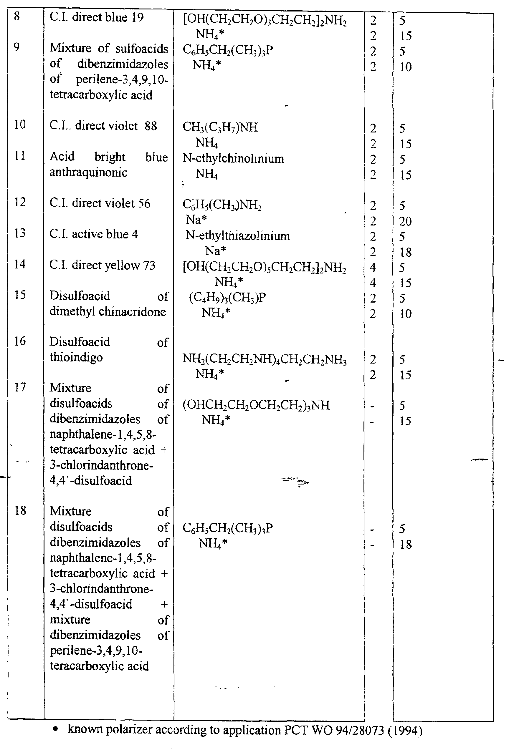

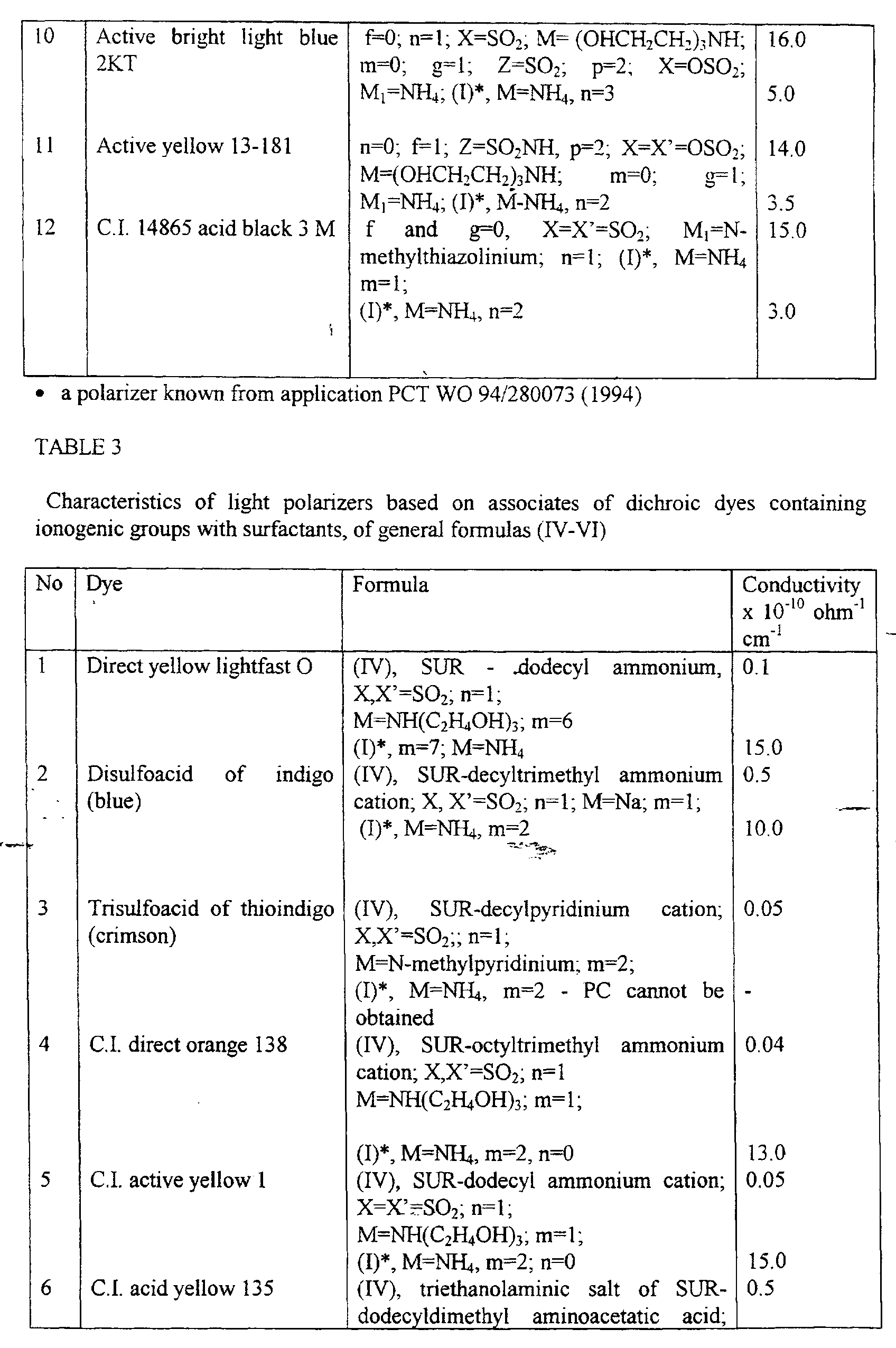

- It should be noted that the above-mentioned polarizers of both the dichroic and interference types based on the birefringent anisotropically absorbing layers having at least one refraction index growing as the wavelength increases, assume the utilization of not more than 50% of the incident light energy.
- Use of the birefringent layer having the abnormal dispersion also allows to produce a polarizer that provides conversion of practically entire energy of a non-polarized radiation source into the polarized radiation.
- The proposed polarizer of said type includes:
- a polarizing means for dividing a plurality of non-polarized light beams, that constitute the light incident on a polarizer, to the same plurality of identical pairs of the differently polarized light beams, and
- a means for changing the polarization of at least one plurality of identically polarized light beams comprised by said plurality of pairs of the differently polarized light beams.
- Said polarizing means implemented in the form of the focusing optical elements, each consisting of at least one birefringent anisotropically absorbing layer adjacent to at least one optically isotropic layer, is optically registered with said means for polarization changing implemented in the form of a sectioned translucent birefringent plate.
- For simplicity, said polarizer will be referred to as the polarizer based on the transmissive type polarizing means.
- The characteristic feature of this polarizer is also the use, in said polarizing means, of at least one birefringent anisotropically absorbing layer having at least one refraction index growing as the polarized light wavelength increases.
- Said focusing optical element of the claimed polarizer can be implemented in the form of a zone plate, which in its turn can be implemented in the form of an amplitude zone plate, wherein the even zones comprise at least one birefringent anisotropically absorbing layer adjacent to at least one optical isotropic layer, and the odd zones are manufactured of an optically isotropic material.
- A phase zone plate can serve as the other version of the zone plate of the claimed polarizer.
- A phase zone plate can have at least one refraction index changing at least along one of the directions, inclusive of that along the plate.
- At least one refraction index of a phase zone plate can change in the direction along the plate plane according to a certain rule, including a non-monotonic change.
- The means for changing polarization of the claimed polarizer can also comprise a sectioned translucent birefringent anisotropically absorbing layer having at least one refraction index growing as the polarized light wavelength increases.
- At least one retraction index of at least one birefringent anisotropically absorbing layer in a polarizer based on a polarizing means of the transmissive type can be directly proportional to the polarized light wavelength.
- At least one birefringent anisotropically absorbing layer of the claimed polarizer can have a thickness whereat the interference extremum at output of a polarizer at least for one linearly-polarized light component is realized. Thereby thickness of at least one birefringent anisotropically absorbing layer satisfies the condition of obtaining, at output of an optical polarizer, the interference minimum for one linearly-polarized component of the passing light and the interference maximum for other orthogonal linearly-polarized component of the passing light.
- For manufacture of the claimed polarizer, layers are selected such that refraction index of the optically isotropic layer will coincide with, or be maximally proximate to one of indices of the birefringent layer.
- Preferable is a polarizer characterized in that the means for changing polarization is implemented in the form of a sectioned translucent half-wave birefringent plate or a layer having sections disposed in focuses or outside focuses of focusing optical elements.
- When in the polarization changing means, used is an 〈〈achromatic〉〉 half-wave or quarter-wave (for circular polarizer) plate, wherein a phase carry-over (or travel difference) is an half or quarter of the wavelength, the polarization change, when light passes through such plate, takes place at all wavelengths of the operating range.
- Another version is a polarizer, characterized in that the polarization changing means is implemented in the form of a sectioned translucent birefringent plate having sections in the form of quarter-wave plates disposed outside focuses of the focusing optical elements, and having sections in the form of plates determining a phase difference between the ordinary and extraordinary rays, that is different by π from the phase difference determined by said sections in the form of quarter-wave plates disposed in focuses of the focusing optical elements.
- The means for changing polarization of the claimed polarizer can be implemented in the form of a sectioned translucent polymerized planar layer of a liquid crystal having the twist structure, wherein the liquid crystal optical axis within thickness of said layer is rotated by angle of 90°, with sections disposed in focuses or outside focuses of the focusing optical elements.
- The claimed polarizer can be implemented in the form of a film or plate comprising said polarizing means in the form of focusing optical elements having different focal power for each polarized component of the non-polarized light incident upon the polarizer, and optically registered with said means for changing polarization of at least one plurality of identically polarized light beams. Said focusing optical elements can be in the form of the volume or phase collecting lenses, or various kinds of them known from the zone plate optics [see G.S. Landsberg, Optics, rev. and suppd. 5th ed., 〈〈Nauka〉〉 publishers, Moscow, 1976].
- A version of the claimed polarizer, for which the wavelength region where the abnormal dispersion is observed, differs from the operating wavelength range, is a polarizer comprising at least one birefringent anisotropically absorbing layer representing a plurality of volume or phase lenses. In this case, by use of appropriate dyes for forming said lenses, it is possible to create a polarizer providing polarization in the IR-region too.
- It should be noted that the focusing optical elements can have not only the form of lenses, but be the form of mirrors, and combined ones.
- A distinguishing feature of the invention is the use, for manufacture of a polarizer, of at least one birefringent anisotropically absorbing layer having the abnormal dispersion, comprised by a polarizing means and implemented in some embodiments of means for changing polarization for at least one polarized light component.
- For forming said birefringent anisotropically absorbing layer having the abnormal dispersion, the materials and techniques used for the above-claimed polarizers of the interference and dichroic types can be utilized.
- The above-discussed versions do not limit the possibility of using other materials for forming birefringent layers for the proposed optical polarizer.
- Selection of the techniques to apply an oriented birefringent material depends on the used material and is not important for the essence of the invention. The polarizing layers of a birefringent material according to the invention can be not only the flat ones, but can be the focusing ones, for example in the form of lenses and/or mirrors.
- Photolithography techniques can be used for creating sectioned birefringent layers. For application of thermotropic polymer materials, extruders, including those having a great number (10-100) of flat dies and allowing to apply many layers of the required thickness of different polymer materials at one run, can be used.
- The final result of any used techniques must be an oriented layer of a birefringent material having, apart from refraction indices that vary at different axes, the dichroism too, with optimum values of absorption indices.
- Principle of operation of the claimed polarizer can be described as follows. A non-polarized light ray is incident on a first flat surface of a polarizer in the form of a film or plate comprising a polarizing means applied thereon. Said non-polarized light ray, passing through the polarizing means in the form of focusing optical elements having different focal power for each polarized component of the incident non-polarized light, is divided into a plurality of pairs of the differently polarized light beams. The resulting plurality of pairs of the differently polarized light beams is, at the same time, the two pluralities of the polarized light beams, wherein, in each of them, the light is polarized identically for all the beams comprised by said plurality. Further, one of these pluralities of light beams comprised by said plurality of pairs of differently polarized light beams can have the form of for example, parallel light beams linearly-polarized in the same plane, and the other plurality of light beams can be in the form, for example, of the light beams linearly-polarized in the plane that is orthogonal to the polarization plane of the first plurality of the beams convergent in focuses of the focusing optical elements, which (focuses) are regularly arranged on a second flat surface of a polarizer, which second surface comprises an applied thereon means for changing polarization of at least one plurality of the identically polarized light beams in the form of a sectioned translucent birefringent plate. At least one plurality of the identically polarized light beams, passing through said polarization changing means disposed on the second surface of the polarizer, changes its polarization such that state of its polarization will be identical with polarization state of the other plurality of the also identically polarized light beams, that also passed through the second boundary of the polarizer. As the result, both said pluralities of the light beams leaving the polarizer based on a polarizing means of transmissive type, become polarized identically, and further both these pluralities of said light beams coming out of the polarizer transfer the light energy amounting to at least over 50% of the energy of the light incident on the light polarizer, and essentially in the same direction.
- The other kind of the claimed polarizer providing conversion of more than 50% of all the energy of a non-polarized radiation-into the polarized one, is a polarizer based on a polarizing means of the reflecting type.
- Said polarizer is implemented in the form of at least one film or plate, whereon applied are a means for converting the incoming non-polarized light into a plurality of identical light beams, a polarizing means for dividing the non-polarized light beams into the polarized passing and reflected light beams having different polarization, and a means for changing polarization and direction of the light beams reflected from the polarizing means.
- A distinguishing feature of the claimed polarizer is a polarizing means comprising at least one birefringent anisotropically absorbing layer having at least one refraction index growing as the polarized light wavelength increases, or a birefringent layer having the constant, across the layer thickness, directions of the optical axes that change across the layer thickness according to a certain rule.
- Depending on the type of the used birefringent layer, division of the non-polarized light beams can be done either as into the linearly-polarized passing and reflected, with orthogonal polarizations, light, or into the circularly polarized passing and reflected, having opposite signs of the polarization rotation, light.
- The means for changing polarization and direction of the reflected light beams of the claimed polarizer can comprise a sectioned metallic mirror.
- Preferable is a polarizer whose polarizing means includes at least one birefringent anisotropically absorbing layer or a birefringent layer having constant, across the layer thickness, optical axes, and where upstream of the sectioned metallic mirror a quarter-wave plate is positioned.
- Also preferable is a polarizer comprising at least one birefringent anisotropically absorbing layer having at least one refraction index that grows as the polarized light wavelength increases.
- Also preferable is a polarizer wherein the wavelength region, where the anisotropic absorption of the birefringent layer is observed, and thus the condition of the abnormal dispersion is met, coincides with the wavelength operating range.
- The most preferable is the use of birefringent anisotropically absorbing layers with at least one refraction index that is directly proportional with the polarized light wavelength.
- The polarizer according to the invention can comprise as at least one birefringent anisotropically absorbing layer, a layer formed of materials used for manufacturing the claimed polarizer of the interference type.
- The above-discussed versions do not limit the use of other materials for forming birefringent anisotropically absorbing layers for the proposed polarizer.
- A birefringent anisotropically absorbing layer in the proposed polarizer can be both a solid and liquid one.
- For manufacture of a birefringent layer having the constant, across the layer thickness, directions of the optical axes, polymer films oriented by uniaxial or biaxial tensions, transparent (not absorbing the light) in the operating wavelength range polymer films can be used.
- An example of birefringent layers having the direction of the optical axis changing across the layer thickness according to a certain rule, is layers of cholesteric liquid crystals. In such layers, the optical axis corresponding to the long axes of the stick-shaped molecules, and, accordingly, to a greater refraction index, is rotated in the mental motion across the thickens remaining to be parallel to the layer plane. The distance across the thickness, whereat the optical axis makes the full rotation at 360° is referred to as the cholesteric spiral pitch. Direction of the optical axis rotation can be both clockwise, and such spiral is referred to as the right one, and counter-clockwise, and such spiral is referred to as the left one. Such structure (texture) of a birefringent layer of cholesteric liquid crystals is referred to as the planar one, or the Grandjean texture. The main optical properties of a birefringent layer of cholesteric liquid crystals of the planar texture are as follows:
- 1. When the light is incident on the layer, there is a region of selective reflection of the light, the spectrum position of which region is proportional to the cholesteric spiral pitch.
- 2. The spectrum width of the light selective reflection region is proportional to the refraction index anisotropy (i.e. the difference between the ordinary and extraordinary refraction indices).
- 3. Within the light selective reflection region, one circularly polarized component of non-polarized light, direction of which component coincides with the cholesteric spiral rotation direction, is reflected completely, the other circularly polarized component of the non-polarized light, direction of which component is opposite to the cholesteric spiral rotation direction, passes through the layer completely.
-
- Thus the planar texture cholesteric liquid crystal layer is a circular polarizer of the reflecting type for both the passing and reflected lights. Such layer can serve as, or can be included into a polarizing means for dividing the non-polarized light beams into the passing and reflected light beams having different polarizations. When necessary, the known quarter-wave plate can be used for converting the circular polarizations into the linear ones.
- Preferable is a polarizer according to the invention, where the polarizing means comprises at least one layer of a cholesteric liquid crystal.
- More preferable is a polarizer according to the invention comprising at least one layer of the cholesteric liquid crystal manufactured of a polymer cholesteric liquid crystal.
- At least one layer of the cholesteric liquid crystal has across its thickness a gradient of the cholesteric spiral pitch and, as the result, has the spectrum width of the light selective reflection band not less than 100 nm.
- The polarizing means of the reflecting type can comprise at least three layers of cholesteric liquid crystals having the light selective reflection band in three different spectrum ranges.
- The means for converting the incoming non-polarized light into a plurality of identical light beams can be implemented in the form of a system of microlenses or microprisms focusing the light beams coming thereto in the direction towards the interior of the polarizer. In particular, a microlens system can be implemented in the form of positive cylindrical microlenses entirely covering the polarizer surface.
- Selection of techniques for manufacture of a polarizer according to the invention depends on the materials to be used for the birefringent layers, and is not important for the invention essence.
- For forming, on the surface of the proposed polarizer, a polarizing coating comprising at least one birefringent layer, the following standard methods can be used: lamination of the preliminarily oriented by drawing polymer films, application of the used materials in the liquid state by a roller, doctor blade, blade in the form of a non-rotating cylinder, application using a slit die, and other methods. In some cases, after a layer is applied, it is dried to remove solvents. In other cases, for example for thermoplastic polymer materials and vitrifying materials, the applied layer is cooled after application.
- The other techniques that can be used to obtain birefringent layers of the materials that form, when applied, the liquid crystal phase, consist in applying such material onto a substrate prepared beforehand for orientation of the liquid crystal phase [US Patent No. 2 524 286 (1950)]. One of these techniques is an uni-directional rubbing of a substrate, or rubbing of a thin polymer layer applied thereon beforehand, which is known and used for orienting thermotropic low-molecular liquid crystal mixes in manufacture of LC-displays.
- Another technique for obtaining birefringent layers is the known technique of photo-orientation of the preliminarily applied, in this or other manner, layer using irradiation thereof by the linearly-polarized ultra-violet light.
- For applying birefringent layers of thermotropic polymer materials, extruders can be used, inclusive of the extruders having a number of flat dies and allowing to apply several layers of different polymer materials of the required thickness at one run.
- For manufacture of a layer of cholesteric liquid crystals of the planar texture, the following materials can be used: cholesteryl esters, nematic liquid crystals doped with optically active compounds, so called chiral nematics wherein the optically active center is chemically connected with molecules of a nematic liquid crystal, polymer cholesteric liquid crystals, lyotropic cholesteric liquid crystals of, for example, polypeptides and cellulose ethers.
- The manufactured layers can be both liquid and solid. Curing of layers can be done be lowering a temperature, by evaporation of a solvent, polymerization, including photo-induced polymerization.
- As the means to convert the incoming non-polarized light into a plurality of identical light beams, a system of microlenses, both the volume and flat Fresnel lenses, as well as the other means for focusing light beams, a system of microprisms in the form of volume prisms of, for example, the triangular shape, or flat prisms having, for example, the distributed across the thickness and surface refraction index, and also other means for deflecting the light rays.
- For manufacture of a system of microlenses or microprisms, the moulding, casting techniques can be used, for example filling the preliminarily prepared depressions of the desired shape in a polymer film with a polymer material having a greater refraction index; photo-induced polymerization, and other techniques.
- For applying a sectioned metallic mirror, the following standard methods can be used: thermal evaporation in vacuum, application in vapours with subsequent thermal treatment, magnetron sputtering, and other methods. For application of a mirror, aluminium (Al), silver (Ag), and other metals can be used.
- Principle of operation of the claimed polarizer based on a polarizing means of the reflecting type will be disclosed in description of the specific examples of this polarizer.
- As it is mentioned above, the above-claimed polarizers can be used in various devices for displaying information, in particular for manufacture of liquid-crystal indicating elements, including flat displays.
- The objective of the invention is to provide improved brightness and colour saturation of the images produced by a liquid-crystal indicating element.
- This objective is to be attained by use of liquid-crystal indicating element (LCI), comprising a layer of liquid crystal positioned between a first and second plates, at least on one of said plates located are electrodes and a polarizer that includes at least one birefringent anisotropically absorbing layer having at least one refraction index that grows as the polarized light wavelength increases.
- For forming said layer, the same materials and techniques as for the above-claimed polarizers, are used.
- An high quality of an image is to be provided by a LCI element comprising at least one polarizer of the interference type having high polarization characteristics.
- The claimed LCI element can further, on one plate, comprise a diffusion reflection layer, which layer is simultaneously an electrode, and at least one birefringent anisotropically absorbing layer being located directly on the reflecting layer, or on a dielectric sub-layer applied on the reflecting coating.
- The other version of the LCI element is characterized in that on one of the plates, an additional layer of colour elements is formed between the polarizer and the plate.
- The polarizer of the claimed LCI element can further comprise at least one layer that reflects the light at least partially. Said light-reflecting layer can be made of a metal.
- At least one birefringent anisotropically absorbing layer of at least one polarizer of the claimed LCI element can be implemented in the form of elements that differ from one another in the aspect of the phase delay and/or the polarization axis direction.
- One polarizer of the claimed LCI element comprises at least two birefringent anisotropically absorbing layers of different colours with mutually perpendicular direction of the polarization axes, applied one upon the other, or on at least one intermediate layer separating them; and on the other plate the polarizer comprises at least one birefringent anisotropically absorbing layer of gray colour having the polarization axis coinciding with the polarization axis direction of one of the birefringent anisotropically absorbing layers on the first plate.
- Use of the polarizer based on the polarizing means of the reflecting type, utilizing more than 50% of the non-polarized light, provides an high brightness and reduces the amount of power consumed by the LCI element.
- The proposed LCI element comprises a liquid crystal layer positioned between the first and second plates, where at least on one of said plates electrodes and the polarizer are positioned. At least one polarizer comprises:
- a polarizing means for dividing a plurality of non-polarized light beams of the light incident upon the polarizer into the same plurality of identical pairs of the differently polarized light beams, which means is implemented in the form of focusing optical elements, each of which comprising at least one birefringent anisotropically absorbing layer having at least one retraction index that grows as the polarized light wavelength increases and is adjacent to at least one optically isotropic layer; said polarizing means being optically registered with a means for changing polarization of at least one of the identically polarized light beams comprised by said plurality of pairs of the differently polarized light beams.
- At least one birefringent anisotropically absorbing layer of the focusing optical element of the claimed LCI element can be implemented in the form of a plurality of the volume or phase lenses.
- The focusing optical element of the claimed LCI element can be implemented in the form of a zone plate.
- A kind of a zone plate is an amplitude zone plate, whose even zones comprise at least one birefringent anisotropically absorbing layer adjacent to at least one optically isotropic layer, and the odd zones being implemented of an optically isotropic material.
- The other kind of a zone plate is a phase zone plate.
- The means for changing polarization of the LCI element can comprise a sectioned translucent birefringent anisotropically absorbing layer having at least one refraction index that grows as the polarized light wavelength increases.
- The polarization changing means can be implemented in the form of a sectioned translucent half-wave birefringent plate, or a layer having sections disposed in focuses or outside the focuses of the focusing optical elements.
- The polarization changing means of the polarizer of the claimed LCI element can be implemented in the form of a sectioned translucent birefringent plate having sections in the form of quarter-wave plates disposed outside the focuses of the focusing optical elements, and having sections determining a phase difference between the ordinary and extraordinary rays, differing by π from the phase difference determined by said sections in the form of quarter-wave plates disposed in focuses of the focusing optical elements.
- The polarization changing means of the claimed LCI element can be implemented in the form of a sectioned translucent polymerized planar layer of a liquid crystal having the twist texture, with the rotation of the liquid crystal optical axis within the thickness of said layer by angle of 90°, with sections disposed in focuses or outside focuses of the focusing optical elements.
- The polarization changing means of the claimed LCI element can be implemented in the form of a sectioned translucent achromatic birefringent plate.
- An increased brightness and a lower power consumption are also provided by the LCI element, using the polarizer based on a polarizing means of the reflecting type.
- The proposed LCI element comprises a liquid crystal layer disposed between a first and second plates, at least on one of which plates positioned are electrodes and a polarizer. At least one polarizer is implemented in the form of at least one film or plate, whereon applied are: means for converting the incoming non-polarized light into a plurality of identical light beams, a polarizing means for dividing the non-polarized light beams into the polarized passing and reflected light beams having different polarizations, which means comprises at least one birefringent anisotropically absorbing layer having at least one refraction index that grows as the polarized light wavelength increases, or a birefringent layer having the constant, across the layer thickness, directions of the optical axes, or a birefringent layer having the optical axes' directions that change across the layer thickness according to a certain rule, and a means for changing polarization and direction of the light beams reflected from the polarizing means.
- The means for changing polarization and direction of the reflected light beams of the claimed LCI element can comprise a sectioned metallic mirror.
- The polarizing means of the LCI element can comprise at least one birefringent anisotropically absorbing layer or a birefringent layer having the constant, across the layer thickness, directions of the optical axes, and having a quarter-wave plate upstream of the sectioned metallic mirror.
- The polarizing means of the claimed LCI element can comprise, as at least one birefringent layer having the optical axes' directions that change across the layer thickness according to a certain rule, at least one layer of a cholesteric liquid crystal that can be manufactured of a polymer cholesteric liquid crystal.
- At least one layer of a cholesteric liquid crystal can have, across the thickness, a gradient of the cholesteric spiral pitch, and, as the result, a spectrum width of the light selective reflection band of not less than 100 nm.
- The polarizing means can comprise at least three layers of cholesteric liquid crystals having the light selective reflection bands in three various spectrum ranges.
- The means for converting the incoming non-polarized light of the polarizer of the claimed LCI element can be implemented in the form of a system of microlenses or microprisms that focus the light beams coming out of them in the direction towards the interior of the polarizer.
- A system of microlenses can be implemented in the form of positive cylindrical microlenses that entirely cover the polarizer surface.
- On a first surface of a film or plate, the polarizer of the claimed LCI element can comprise a system of microlenses and a sectioned metallic mirror optically registered with said system of microlenses, and on a second surface of a film or plate it can comprise at least one layer of a cholesteric liquid crystal.
- The polarizer of the claimed LCI, on the first surface of a film of plate, can comprise a system of microlenses, a sectioned metallic mirror optically registered with said system of microlenses, and a quarter-wave plate; and on the second surface the polarizer further comprises at least one birefringent anisotropically absorbing layer or a birefringent layer having the constant, across the layer thickness, directions of the optical axes.
- The polarizer, on the first surface of a film or a plate, can also comprise a sectioned metallic mirror, and on the second surface of film or plate applied are, sequentially, a system of microlenses optically registered with sections of the metallic mirror, and at least one layer of a cholesteric liquid crystal.
- Preferable is a LCI element whose polarizer on the first surface of a film or plate comprises a sectioned metallic mirror and a quarter-wave plate, and on the second surface of a film or plate sequentially applied are a system of microlenses optically registered with sections of the metallic minor and at least one birefringent anisotropically absorbing layer or a birefringent layer having the constant, across the layer thickness, directions of the the optical axes.
- The polarizer of the claimed LCI element can comprise at least two laminated films or plates; on the external surface of the first film or plate applied is a first system of microlenses, on the internal surface of the first or second film or plate applied is a sectioned metallic minor, and on the external surface of the second film or plate additionally applied is the second system of microlenses optically registered with sections of the metallic mirror and with the first system of microlenses; and at least one layer of a cholesteric liquid crystal.
- Preferable is a LCI element whose polarizer comprises at least two laminated films or plates; on the external surface of the first film or plate applied is a first system of microlenses, on the internal surface of the first or second film or plate applied are a sectioned metallic mirror and a quarter-wave plate, on the external surface of the second film or plate additionally applied are the second system of microlenses optically registered with sections of the metallic minor and with the first system of microlenses, and at least one birefringent anisotropically absorbing layer or a birefringent layer having the constant, across the layer thickness, directions of the optical axes.
- Preferable is a LCI element whose polarizer comprises at least two laminated films or plates; on the external surface of the first film or plate applied is a system of microprisms, on the internal surface of the first or second film or plate applied is a sectioned metallic mirror optically registered with the system of microprisms, on the external surface of the second film or plate applied is at least one layer of a cholesteric liquid crystal.
- Preferable is a LCI element whose polarizer comprises at least two laminated films or plates, on the external surface of the first film or plate applied is a system of microprisms, on the internal surface of the first film or plate sequentially applied are a sectioned metallic mirror optically registered with the system of microprisms, and a quarter-wave plate; on the external surface of the second film or plate applied is at least one birefringent anisotropically absorbing layer or a birefringent layer having the constant, across the layer thickness, directions of the optical axes.
- Preferable is a LCI element whose at least one polarizer further comprises an orienting layer formed of non-organic materials or on the basis of polymer materials.
- The orienting layer can be formed both on the birefringent anisotropically absorbing layer, and between the substrate and said layer.
- Another version is a LCI element, characterized in that at least on one of the plates at least one birefringent anisotropically absorbing layer of at least one polarizer is disposed on a transparent electrode, or between the plate and the electrode, or on a dielectric film covering the transparent electrode, or between the layer that orients the liquid crystal and a dielectric sub-layer that covers the electrode, or on the reverse side of the layers.
- Preferable is a LCI element, characterized in that on one plate formed is a diffusion-reflection coating that can simultaneously serve as an electrode, and at least one birefringent anisotropically absorbing layer being disposed directly on the reflecting coating or on a dielectric sublayer applied on the reflecting coating, or between the layer that orients the liquid crystal and the other layers applied on the reflecting coating.
- At least one birefringent anisotropically absorbing layer used in all above-cited versions of the LCI element can have at least one refraction index that is directly proportional to the polarized light wavelength.
- At least one birefringent anisotropically absorbing layer of at least one polarizer in all above-cited versions of the LCI element can have a thickness whereat the interference extremum at output of the polarizer at least for one linearly-polarized light component is realized.
- Thickness of at least one birefringent anisotropically absorbing layer of at least one polarizer in all above-cited versions of the LCI element can satisfy the condition of obtaining the interference minimum at output of the polarizer for one linearly-polarized light component and the interference maximum for the other orthogonal linearly-polarized light component.
- At least one polarizer in all above-cited versions of the LCI element comprising at least two layers, comprises, as at least one of them, a birefringent anisotropically absorbing layer, and the other layer is the optically isotropic one whose refraction index coincides with, or maximally proximate to one of the indices of a birefringent layer.
- At least one polarizer in all the above-cited versions of the LCI element comprising at least two birefringent layers, comprises, as at least one of them, the anisotropically absorbing layer, one refraction index of which layer coincides with, or maximally proximate to one of the indices of the birefringent layer, and the second retraction indices of the birefringent layer and the birefringent anisotropically absorbing layer differ from one another.
- By varying the used dyes in a LLC composition, LC-devices with different colour, including the gray one, can be created. The gray colour can be also obtained by the layer-by-layer application of a birefringent anisotropically absorbing layer of yellow, red and blue colours when they are formed on plates of a dish.
- Use of an associate of dichroic dyes comprising ionogenic groups with at least one mole of an organic, particularly surface-active ion for forming a birefringent anisotropically absorbing layer provides a good orienting capability of a polarizer when it is disposed inside a LCI element, whereby the necessity to apply additional orienting LC layers is avoided. By varying the structure of an organic ion, the orienting and wetting capabilities of solutions in manufacturing polarizers can be changed, which is important for manufacturing LCI elements of various types.
- Further, the presence of low-motion organic ions in polarizing coatings provides a low conductivity, which in its turn lowers the energy consumption, thus extending service life of liquid crystal devices. Thereby the necessity to apply additional insulating layers when polarizers are disposed internally is avoided.
- Variety of the colour arrangements of the claimed LCI element is provided by using the most different dyes, for example those of (II-VI) formulas, for manufacture of polarizers.
- Use of the interference polarizers based on birefringent anisotropically absorbing layers provides an high brightness and homogeneity across the surface of the claimed LCI element, as well as good angular characteristics and the absence of shadows in operation for the reflection.
- An increased brightness of a LCI element with simultaneous lowering of the energy consumption is achieved by a polarizer utilizing more than 50% of the incident light energy.
- Use of the above-mentioned materials for forming birefringent anisotropically absorbing layers provides the possibility to manufacture both monochromatic and colour LCI elements and displays based thereon.
- To attain an high brightness and contrastness of the image in the proposed device intended for manufacturing the high-resolution displays, additional orienting and brightening layers can be used alongside with birefringent anisotropically absorbing layers.
- Use of the claimed polarizers based on birefringent anisotropically absorbing layers does not exclude the use of conventional film-based polarizing films, in particular iodine polarizers based on PVA. For example, combination of the internal polarizer on the 1st plate having a iodine-based reflecting or transmissive polarizer glued onto the external side of the second plate, allows to create a device having an high image brightness and contrast and not requiring an additional glass usually used to protect a polarizer glued onto the external side of a first glass.
- Further, using a polarizer based on birefringent anisotropically absorbing layers, LC indicating elements with the external arrangement of polarizers can be manufactured. For this purpose, birefringent anisotropically absorbing layers are applied on a transparent isotropic polymer film, whereafter the so produced film polarizer is glued onto the external side of the plates. It should be noted that the LC device produced in this way comprises much less layers as compared with the LC device having conventional polarizers based on the PVA films.
- A polarizer of the interference type according to the invention is illustrated by certain examples of the specific embodiment as shown in Figs. 1-3. Fig. 1 schematically shows a one-layer polarizer of the reflecting type according to the invention. Fig. 2 schematically shows kinds of dependencies of the refraction index of layers in polarizers on the light wavelength. Fig. 3 schematically shows a multi-layer polarizer according to the invention.
- A polarizer of the dichroic type and a circular polarizer based thereon are represented in Fig. 4-5.
- A polarizer based on a polarizing means of the transmissive type according to the invention is illustrated by specific examples of a particular embodiment shown in Figs. 6 - 12.
- Fig. 6 schematically shows a cross section of one version of the proposed polarizer implemented in the form of one film, on whose surface applied is the following: a polarizing means in the form of volume lenses made of birefringent anisotropically absorbing material, and a means for changing polarization of polarized light beams in the form of a sectioned translucent birefringent plate, sections of which plate are disposed in focuses of said volume lenses. Fig. 7 schematically shows a general view of the proposed polarizer according to Fig. 6. Fig. 8 schematically shows a cross-section of one of versions of the proposed polarizer implemented in the form of one film, on the surface of which film applied are: a polarizing means in the form of said volume lenses, and a means for changing polarization of the polarized light beams, implemented in the form of a sectioned translucent birefringent plate whose sections are disposed outside focuses of said volume lenses. Fig. 9 schematically shows a cross-section of a version of the proposed polarizer in the form of one film, on the surface of which film applied are: a polarizing means in the form of amplitude zone plates made of interleaving layers of birefringent and optically isotropic materials, and a means for changing polarization of the polarized light beams implemented in the form of a sectioned translucent birefringent plate having sections in the form of quarter-wave plates disposed outside focuses of said amplitude zone plates and sections determining the phase difference between the ordinary and extraordinary rays, differing by π from the phase difference determined by said sections in the form of quarter-wave plates disposed in focuses of said amplitude zone plates. Fig. 10 presents a cross section of one of the possible designs of an amplitude zone plate used in the version of the proposed polarizer according to Fig. 9. Fig. 11 shows a cross section of a phase zone plate made of three layers, one of which is birefringent anisotropically absorbing one, and two other are optically isotropic with different refraction indices: one index is equal to the ordinary retraction index of a birefringent layer, the other being equal to the extraordinary one. Boundaries of these layers have a surface profile allowing them, when said ratios of the refraction indices exist, to play the role of arrays of identical phase zone plates capable of focusing the rays that are linearly-polarized in mutually orthogonal planes. These arrays of phase zone plates are shifted with respect to one another by an half width of one such zone plate. Fig. 12 shows a cross section of a version of the proposed polarizer in the form of a film, on the surface of which film applied are: a polarizing means in the form of phase zone plates of the interleaving birefringent anistropically absorbing and optically isotropic materials, the design of which plates is shown in Fig. 11, and a means for changing polarization of the beams of the polarized light implemented in the form of a sectioned translucent birefringent plate, whose sections are disposed in focuses of said volume lenses.
A polarizer based on a polarizing means of the reflecting type according to the invention is illustrated by specific examples of the particular embodiment shown in Fig. 13 - 21. - Fig. 3 schematically shows a cross section of the proposed polarizer, characterized in that it is implemented in the form of one film or plate, on a first surface of which film or plate applied is a system of microlenses and a sectioned metallic mirror, on a second surface thereof applied is a polarizing means including at least one layer of a cholesteric liquid crystal. Fig. 14 schematically shows a general view of the proposed polarizer according to Fig. 13. Fig.15 schematically shows a cross section of the proposed polarizer, characterized in that the same is implemented in the form of one film or plate, on a first surface of which film or plate applied are a system of microlenses, a sectioned metallic mirror and a quarter-wave plate, and on a second surface thereof applied is a polarizing means including at least one birefringent layer having the constant, across the layer thickness, directions of the optical axes. Figs. 16 and 17 schematically show a cross section of the proposed polarizer, characterized in that the same is implemented in the form of one film or plate, on a first surface of which film or plate applied is a sectioned metallic mirror, and on a second surface thereof applied is a polarizing means and a system of microlenses. Figs. 18 and 19 schematically show a cross section of versions of the proposed polarizer implemented in the form of two laminated films or plates, on whose external surfaces applied are a polarizing means and two systems of microlenses, and on the internal surfaces thereof applied is a sectioned
metallic minor 37. Figs. 20 and 21 schematically show a cross section of versions of the proposed polarizer implemented in the form of two laminated films or plates, on whose external surfaces applied are a polarizing means and a system of microprisms, and on the internal surfaces thereof applied is a sectionedmetallic mirror 37. - Examples of the claimed LCI elements in the most typical configurations are shown in Figs. 22-27. Fig. 22 schematically shows an element of the transmissive type based on a conventional twist-nematic; Fig. 23 schematically shows LCI element of the transmissive type based on a conventional twist-nematic, having other arrangement of the polarizing layer and electrodes; Fig. 24 schematically shows a LC indicator of the reflecting type based on a conventional twist-nematic; and Fig. 25 schematically shows a LC indicator of the transmissive type based on a supertwist-nematic; Fig. 26 schematically shows a LC indicator comprising the colour-switching effect, and Fig. 26 schematically shows a matrix LC indicator.
- Fig. 1 shows a diagram of a one-layer polarizer of the reflecting type according to the invention, comprising birefringent
anisotropically absorbing layer 1, said polarizer is characterized in that both its refraction indices (extraordinary ne and ordinary no) are proportional to the polarized light wavelength. In the most simple version,layer 1 is adjacent from two sides to air. In more complex versions, on one of its surfaces applied is a light-reflecting coating.Layer 1 can be applied also on a substrate, and be, for example, of a transparent glass (shown in Fig. by phantom line). Operation of the proposed polarizer of the reflecting type can be explained as follows. The non-polarized light consists of two linearly-polarizedcomponents anisotropically absorbing layer 1, is partially reflected from the boundary oflayer 1, thus formingray 3. A partial reflection of light of the boundary of interface betweenlayer 1 and the medium takes place due to a jump (difference) of refraction index at said boundary. For a partial reflection of light, a light-reflecting coating additionally applied onlayer 1 can be used. The other portion of energy ofcomponent 2, having passed through birefringentanisotropically absorbing layer 1, is reflected from the second boundary oflayer 1, and passes throughlayer 1 once again, thus formingray 4. The reflected rays 3 and 4 are polarized in the same way ascomponent 2. - Thickness of
layer 1 is selected such that the optical difference of travel Δe forrays layer 1 are transparent (non-absorbing) and have refraction indices that are less than those oflayer 1, then the optical difference of travel israys rays rays layer 1, for example, owing to an additionally applied light-reflecting coating. The light-reflecting coating can be a metallic or dielectric one, of the one-layer, or multi-layer type. When the condition of proportionality of the extraordinary refraction index of birefringentanisotropically absorbing layer 1 to light wavelength (ne ∼ λ) is met, then equality - The other linearly-polarized
component 5, polarized perpendicularly to the optical axis of birefringentanisotropically absorbing layer 1, is partially reflected from the first boundary oflayer 1, thus formingray 6. The other portion ofcomponent 5, having passed throughlayer 1, is reflected from the second boundary oflayer 1, passeslayer 1 once again, thus formingray 7. The reflected rays 6 and 7 are polarized in the same way asincoming component 5. The result of interference ofrays ray 6 is reflected from the first boundary oflayer 1 also occurs for this component). When the condition of proportionality of the ordinary refraction index of birefringentanisotropically absorbing layer 1 to light wavelength (ne ∼ λ) is met, then equality of - Thus, in a wide spectrum range, as the result of interference, the total reflection of
component 2, polarized in parallel to the quick axis oflayer 1 of a birefringent material, is much smaller than reflection ofcomponent 5 that polarized perpendicularly to the quick axis oflayer 1. - Also possible realization of the reverse situation when as the result of the interference, the total reflection of
component 2 polarized in parallel to the optical axis oflayer 1 ofbirefringent material 1 is much greater than reflection ofcomponent 5 polarized perpendicularly to the optical axis oflayer 1. This situation can take place when thickness oflayer 1 is selected such that the optical difference of travel Δe forrays rays rays rays component 2, polarized in parallel to the optical axis oflayer 1 of a birefringent material, is much greater than reflection ofcomponent 5, polarized perpendicularly to the optical axis oflayer 1 of a birefringent material. - Fig. 2 schematically shows dependencies of the refraction index of layers in polarizers on the visible light wavelength, i.e. in the region of 400-700 nm. Curve 8 corresponds to the polarizer according to the prototype, wherein the retraction index of layers decreases as the light wavelength increases. Such dependency in optics referred to as the normal dispersion, and is characteristic for transparent materials.
Curve 9 corresponds to the polarizer according to the invention, wherein at least one refraction index of layers grows as the light wavelength increases. Such dependency in optics is referred as to the abnormal dispersion, and for the purpose to realize such dependency a polarizer must be designed in a special way. The carried-out experiments and analyses have shown that for this purpose preferable is a polarizer, characterized in that at least one birefringent anisotropically absorbing layer has the maximal refraction index not less than 0.1 in the operating wavelength range. Here, as in optics, retraction index of the manufactured layer k is determined (see also GOST standard 7601-78) as a coefficient at the virtual portion in the universal retraction index of a manufactured layer of a material - It should be noted that the wavelength range wherein the anisotropic absorption takes place and, consequently, the abnormal dispersion is observed, can coincide and not coincide with the wavelength operating range. For the claimed polarizers of the interference type, preferable is a wavelength operating range, wherein the abnormal dispersion is observed, i.e. at least the refraction index grows as the light wavelength increases.
- Fig. 3 schematically shows a multi-layer polarizer according to the invention, comprising 4 birefringent
anisotropically absorbing layers 1, characterized in that the extraordinary refraction index ne of these layers grows as the polarized light wavelength increases.Said layers 1 are applied as interleaved with fourlayers 11 of an optically isotropic material, the ordinary refraction index no of a birefringent material coinciding with, or being proximate to refraction index ni of the optically isotropic material. The birefringentanisotropically absorbing layers 1 can be implemented as being identical, or of different materials, being different, for example, in respect of spectrum ranges, within which ranges the extraordinary refraction index ne grows as the wavelength increases. - Operation of the proposed polarizer can be explained as follows. A non-polarized light consists of two linearly-polarized
components Component 2 that is polarized in parallel to the optical axis birefringent anisotropically absorbinglayers 1, is partially reflected from boundaries oflayers 1 and opticallyisotropic layers 11, thus formingrays 3. The reflected rays 3 are polarized in the same way asincoming component 2. - Thickness of
layers 1 is selected such that the result of interference of allrays 3 is the interference maximum, i.e their mutual intensification. The reflectance thereby reaches 98-99.9%, which means that linearly-polarizedcomponent 2 is practically completely reflected from a polarizer, formingray 12. When a more rigorous, than simple increase, condition is satisfied, namely the condition of the direct proportionality of the extraordinary refraction index of birefringentanisotropically absorbing layers 1 to the light wavelength (ne - λ), the interference maximum condition will be met for the whole operating wavelength range. - To the other non-polarized
light component 5, that is linearly-polarized perpendicularly to the optical axis oflayers 1, corresponds the ordinary refraction index no oflayers 1, being equal to refraction index ni of the optically isotropic layer (layers component 5 passes through a multi-layer polarizer completely, without any reflections, thus formingray 13. Reflection ofcomponent 5 from the external surfaces of a polarizer can be eliminated using the usual method of 〈〈brightening〉〉, i.e. by applying on the external surfaces the isotropic layers having the optical thickness about a quarter of wavelength and refraction index of no 1/2. - As the result, the polarized light impinging upon a multi-layer polarizer is divided into two parts and transformed into linearly-polarized
ray 12 that passes through a polarizer, and orthogonally polarizedray 13 reflected from a polarizer. - The above-discussed examples do not limit the possible versions of specific embodiments of the proposed polarizer.
- Thus, in all the above-cited examples, provided are high polarization characteristics of a polarizer in a wide spectrum region, when not more than 10 layers are used.
- Principle of operation of the captioned polarizer is based on that the polarized light while passing trough said layer is partially absorbed by the chromophore system of a dye. Thereby passes only that portion of the light waves, wherein direction of oscillations of the electromagnetic field electric component is perpendicular to optical transition dipole moment (Fig. 4).
- When a birefringent anisotropically absorbing layer is applied on a quarter-wave birefringent plate or a film at angle of 45° to the main optical axis of a substrate, a circular polarizer can be manufactured (Fig. 5, a and b are directions of the ordinary and extraordinary rays, respectively, n is the polarizing layer polarization vector direction). Thickness of a birefringent film must satisfy the following condition:
- Fig. 6 schematically shows a cross section of one version of the proposed polarizer implemented in the form of one
film 11, on the surface of which film applied are: a polarizing means in the form ofvolume lenses 15 made of a birefringent anisotropically absorbing material, and means for changing polarization ofbeams 18 of the polarized light, implemented in the form of a sectioned translucent half-wave birefringent plate,sections 19 of which plate are disposed in focuses of saidvolume lenses 15. The means for changing polarization ofbeams 18 of the polarized light can be also implemented in the form of a sectioned translucent polymerized birefringent layer of a liquid crystal having the twist structure, with rotation of the optical axis of the liquid crystal within thickness of said layer at angle of 90°, sections of which layer are also disposed in focuses of saidvolume lenses 15. - Operation of the proposed polarizer can be explained as follows (for better understanding, in Fig. 6 travel of rays of
different polarizations extensions volume lenses 15 are disposed. Passing throughvolume lens 15 made of a birefringent material -optical axis 16 being in the pattern plane and the ordinary refraction index being equal to refraction index of the isotropic material offilm 11, -component 17 that is linearly-polarized perpendicularly to the pattern plane, having passedlens 15, does not undergo refraction at the boundary of interface oflens 15 andfilm 11, owing to which circumstancelight beam 17, retaining the direction and shape ofincident light beam 14, passes through the second boundary offilm 11, thus forming parallellight beam 13, polarized perpendicularly to the pattern. Sectioned translucent half-wave birefringent plate practically does not affect polarization of parallel light beams 13, for the transverse dimensions of itssections 19 are selected as to be much smaller than those of volume lenses 15 (for example, the transverse dimensions ofsections 19 of a half-wave plate are 10 mcm, and those of microlenses are 100-200 mcm). Passing throughvolume lens 15 made of a birefringent material -optical axis 16 being disposed in the pattern plane, and the extraordinary refraction index exceeding refraction index of the isotropic material of film 11 -component 18 that is linearly-polarized in the pattern plane, having passed throughlens 15, is focused on the second surface offilm 11, where disposed issection 19 of the sectioned translucent half-wave birefringent plate, which section, when convergentlight beam 18 passes therethrough, changes polarization of said beam, thus forming divergentlight beam 20, that is linearly-polarized perpendicularly to the pattern plane. Such change of the polarization plane is caused by the known optical properties of a translucent half-wave birefringent plate having the optical axis directed at angle of 45° to the plane of polarization of the light incident thereto. Thus, as the result of operation of this polarizer, energy ofnon-polarized light 14 is converted into energy of the outcoming highlypolarized beams - Fig. 7 schematically shows a general view of the proposed polarizer, a cross section of which polarizer is shown in Fig. 6. This polarizer is implemented in the form of a film or
plate 11, on a first surface of which film or plate applied is a system ofcylindrical microlenses 15 made of a birefringent material, and on a second surface of film orplate 11 applied is a means for changing polarization of the linearly-polarized light beam incident thereon, which means has the form of a system ofstrips 19 of translucent birefringent films, said system being optically registered with said system ofcylindrical lenses 15. Fig. 7 also shows the travel ofbeam 14 of non-polarized light incident on polarizer, and the travel of direction-coincident beams - Fig. 8 schematically shows a cross section of one version of the proposed polarizer implemented in the form of
film 11, on the surface of which film applied are: a polarizing means implemented in the form of saidvolume lenses 15, and a means for changing polarization ofbeams 17 of polarized light, implemented in the form of a sectioned translucent half-wave birefringent plate,sections 21 of which plate are disposed outside focuses of saidvolume lenses 15. The means for changing polarization ofbeams 17 of the polarized light can also be implemented in the form of a sectioned translucent polymerized birefringent layer of a liquid crystal having the twist structure, with rotation of the optical axis of the liquid crystal within thickness of said layer at angle of 90°, sections of which layer are also disposed outside focuses of saidvolume lenses 15. - Operation of the proposed polarizer can be explained as follows (for the sake of clarity, in Fig. 8 the travel of rays of
different polarizations extensions volume lenses 15 are disposed. -
Component 17, linearly-polarized perpendicularly to the pattern plane, passing throughvolume lens 15 made of a birefringent material -optical axis 16 being disposed in the pattern plane and the ordinary refraction index being equal to refraction index of the isotropic material of film 11- and having passed through saidlens 15, does not undergo any refraction at the boundary of interface oflens 15 andfilm 11, so thatlight beam 17 retains the direction and shape ofincident light beam 14. Passing through the second boundary offilm 11, whereonsections 21 of the sectioned translucent half-wave birefringent plate are disposed,light beam 17 changes its polarization, thus formingparallel beam 22 of the light polarized in the pattern plane. Such change of the polarization plane is caused by the known optical properties of a translucent half-wave birefringent plate having the optical axis directed at angle of 45° to the plane of polarization of the light incident thereon. Intervals betweensections 21 of the sectioned translucent half-wave birefringent plate do not practically affect polarization of parallel light beams 46, because the transverse dimensions of itssections 19 are selected as to he much smaller than those of volume lenses 15 (for example, the transverse dimensions of intervals betweensections 19 of a half-wave plate are 10 mcm, and those of microlenses are 100-200 mcm). Passing throughvolume lens 15 made of a birefringent material -optical axis 16 being disposed in the pattern plane, and the extraordinary refraction index exceeding refraction index of the isotropic material offilm 11, -component 18 that is linearly-polarized in the pattern plane, having passed throughlens 15, is focused on the second surface offilm 11, thus reaching the interval between twoneighbouring sections 21 of the sectioned translucent half-wave birefringent plate and then leaving the polarizer in the form of divergentlight beam 23 that is polarized, asbeam 18, in the pattern plane. Thus, as the result of operation of this polarizer, energy ofnon-polarized light 14 is converted into energy of the outcoming highlypolarized beams - Fig. 9 schematically shows a cross section of one version of the proposed polarizer implemented in the form of
film 11, on surface of which film applied are: a polarizing means in the form ofamplitude zone plates 24 made of interleaving layers of the birefringent and optically isotropic materials, and a means for changing polarization ofbeams plate having sections 25 in the form of quarter-wave plates disposed outside focuses of saidamplitude zone plates 24, and havingsections 26 in the form of plates determining the phase difference between the ordinary and extraordinary rays, being different by λ from the phase difference determined by saidsections 25 in the form of quarter-wave plates disposed in focuses of saidamplitude zone plates 24. - Operation of the proposed polarizer can be explained as follows (for clarity, in Fig. 9 the travel of rays of
different polarizations extensions amplitude zone plates 24. Linearly-polarized perpendicularly to thepattern plane component 17, passing throughamplitude zone plate 24 made of interleaving layers of a birefringent anisotropically absorbing material and optically isotropic material -optical axis 16 of said birefringent material being disposed in the pattern plane, and its ordinary refraction index being equal to refraction index of said isotropic material, having passed zone plate, is not reflected in any way from boundaries of interface of interleaving birefringent and isotropic layers, so thatlight beam 17 continues to retain the direction and shape ofincident light beam 14. Beam of light 17 that is linearly-polarized perpendicularly to the pattern plane, passing through the second boundary offilm 11, whereon, outside the focus of saidamplitude zone plate 24, disposed aresections 25 of the sectioned translucent quarter-wave birefringent plate, changes its polarization, thus formingparallel beam 27 of the circularly polarized light. Thereby the translucent birefringentplate having sections 26, disposed in intervals between saidsections 25 of the translucent quarter-wave birefringent plate, and determining the phase difference between the ordinary and extraordinary rays differing by π from the phase difference determined by. saidsections 25 of the translucent quarter-wave birefringent plate, does not practically affect polarization of parallel light beams 27, because its transverse dimensions are selected to be much smaller than the transverse dimensions of amplitude zone plate 24 (for example, the transverse dimensions ofbirefringent plate 26 are 10 mcm, and the transverse dimensions of the amplitude zone plate are 100-200 mcm). Linearly-polarizedcomponent 18, that is polarized in the pattern plane, passing throughamplitude zone plate 24 made of interleaving layers of the birefringent anisotropically absorbing and optically isotropic materials - theoptical axis 16 of said birefringent material being disposed in the pattern plane, and the extraordinary refraction index thereof exceeding refraction index of said isotropic material, - having passedzone plate 24, is focused on the second surface offilm 11, whereon disposed aresections 20 of the translucentbirefringent plate 11 determining the phase difference between the ordinary and extraordinary rays, differing by π from the phase difference determined bysections 25 of the translucent birefringent plate, which sections are quarter-wave plates and when the convergent, linearly-polarized in the pattern plane,light beam 18 passes through them, they change its polarization, thus formingdivergent beam 28 of the circularly polarized light of the same sign as the circularly polarized light inbeam 27. Such change of the polarization plane ofbeams non-polarized light 14, to an extent over 50%, is converted into the energy of the outcoming highlypolarized beams - Fig. 10 shows a cross section of one of the possible designs of an amplitude zone plate used in the version of the proposed polarizer according to Fig. 9. In design of
amplitude zone plate 24, cross section of which plate is shown in Fig. 10, used areregions 1 of a birefringent anisotropically absorbing material having refraction indices no of the ordinary ray, and ne of the extraordinary ray, whose conventionally designatedoptical axes 16 are disposed in the pattern plane and positioned between layers of the opticallyisotropic material light beams 5 that are polarized perpendicularly to the pattern plane, forming at output of said amplitude zone plate aparallel light beam 17, linearly-polarized perpendicularly to the pattern plane, and transmitsrays 29, delayingrays 2, both of them being linearly-polarized in the pattern plane, forming fromrays 29, owing to diffraction,convergent beam 18 that is also linearly-polarized in the pattern plane. To provide the above-described operation of said amplitude zone plate, certain relationships must be maintained between refraction indices ne, no, light wavelength λ, thickness oflayer 1, as well as between thicknesses layers 30 and 32 that provide the absence of transmission ofbeams 2 linearly-polarized in the pattern plane by zones of said amplitude zoneplate having portions 1 of layers made of a birefringent material owing to the phenomenon of interference in thin films. For example, for the case shown in Fig. 10, this relationship has the form ofparallel one 17 and theconvergent one 18, which beams have the linear polarization in two mutually orthogonal planes. - Fig 11 shows a cross section of a phase zone plate made of three layers, one of which 11 is the isotropic layer and has refraction index n1, the other layer 1is the birefringent anisotropically absorbing one, having refraction index n1 along
axis 16 lying in the pattern plane, and n2 > n1 alongaxis 33 perpendicular to the pattern plane, and the following thelatter layer 30 is the isotropic one, as the first one, but having refraction index n2.Boundaries layers phase zone plates - Operation of the phase zone plate shown in Fig 11 can be explained as follows. A ray of non-polarized light 14 being a superposition of two linearly-polarized orthogonally to one another
rays layer 11 and reachedboundary 34 oflayers layer 1, is divided into two rays:ray 18 polarized in the pattern plane, andray 17 polarized perpendicularly to the pattern plane. Further, owing to the fact that refraction index ofisotropic layer 11 and refraction indexbirefringent layer 1 for the light wave polarized alongaxis 16 are identical,ray 2 that is also polarized alongaxis 16, passes through the phase zoneplate having boundary 34 oflayers ray 18 directed similarly toray 2, i.e. travelling perpendicularly to the polarizer plane and having the same polarization. For the reason that refraction index ofisotropic layer 11 and refraction index ofbirefringent layer 1 for the light wave polarized alongaxis 33 are not identical,ray 5, polarized alongaxis 33, passes through boundary oflayers ray 17 that is deflected from the direction of propagation ofray 5 to the focus of said phase zone plate. Further,ray 17 polarized perpendicularly to the pattern plane, continuing its, inclined to the layers' plane, propagation inlayer 1, reaches another phase zoneplate having boundary 35 betweenlayers ray 13 polarized, similarly toray 17, perpendicularly to the pattern plane and propagating inlayer 30 without changing the direction, i.e. along the direction of propagation ofray 17, because refraction index ofisotropic layer 30 and refraction index ofbirefringent layer 1 for the light, polarized alongaxis 33 that is perpendicular to the pattern plane, are identical. For the reason that refraction index ofisotropic layer 30 and refraction index ofbirefringent layer 1 for the light wave polarized alongaxis 16 are not identical,ray 18 polarized alongaxis 16 passes throughboundary 35 oflayers ray 22 that is deflected from the direction of propagation ofray 18 to the focus of the phase zoneplate having boundary 35 betweenlayers - Fig. 12 schematically shows a cross section of a version of the proposed polarizer, whose polarizing means is implemented in the form of an array of
phase zone plates Rays phase zone plates non-polarized light 14 is incident. On the output surface of the polarizer also disposed aresections 19 of a sectioned translucent half-wave birefringent plate being a means for changing polarization of the linearly-polarized light beams, having the polarization plane disposed at angle of 45° to the direction of the optical axis of said half-wave plate. They change polarization oflight beams 22 polarized in the pattern plane to the orthogonal polarization, converting them into light beams 20. Due to the action effected by said means for changing polarization, rays 20 and 36 that leave the polarizer become polarized identically, i.e. in this case - perpendicularly to the pattern plane. Thus, as the result of operation of the polarizer the energy ofnon-polarized light 14 is converted, to an extent exceeding 50%, into the energy of the outcoming highlypolarized beams - The illustrated in Fig. 6 - 9 and 12 designs of means for dividing each of the non-polarized light beams into two linearly-polarized light beams having different mutually orthogonal linear polarizations, and designs of the means for changing polarization of at least one of said linearly-polarized light beams can be combined also in other possible versions.
- Thus, the use of a birefringent material having at least one refraction index growing as the wavelength of the polarized light increases, allows to create a polarizer that will provide conversion of more than 50% of all the energy of the non-polarized radiation into the polarized radiation, while having a relatively simple design being a film or plate, on surface of which film or plate applied is a polarizing means in the form of focusing optical elements implemented of said birefringent layer and optically registered with the applied on the film or plate surface a means for changing polarization implemented in the form of a sectioned translucent birefringent plate or a layer.
- Fig. 13 schematically shows a cross section of the proposed polarizer according to
version 1 implemented in the form of one film orplate 11, on a first surface of which film or plate sequentially applied are a system ofmicrolenses 38 and a sectionedmetallic mirror 37 optically registered with said system of microlenses, and on the second surface thereof applied is ameans 39 for dividing the non-polarized light beams into the polarized passing and reflected light beams, that includes at least one layer of a cholesteric liquid crystal. - Operation of the proposed polarizer can be explained as follows (for the sake of clarity, in Fig. 13 the travel of rays is shown in a simplified way, without taking into account the refraction at boundaries of different layers, and oily for one microlens). Non-polarized light 14 is incident on a first surface of the polarizer and focused by microlenses to the direction inside the polarizer, forming light beams 41. A sectioned
metallic mirror 37 does not practically shield thenon-polarized light 14, because the transverse dimensions of its light-reflecting elements are selected to be much smaller than the transverse dimensions of microlenses (for example, the transverse dimensions of the light-reflecting elements are 10 mcm, and the transverse dimensions of microlenses are 100-200 mcm). The, focused bylenses 38, light beams 41 reach means 39 for dividing the non-polarized light beams into the polarized passing and reflected light beams that include at least one layer of cholesteric liquid crystal. Thereby, approximately an half of the light energy of non-polarized light beams 41 is converted into the energy of passing light beams 27, for example with the right circular polarization (the direction of the circular polarization of the passing light beams is opposite to the sign of the spiral of the used cholesteric liquid crystal). The other half of the light energy of non-polarized light beams 41 is converted into the energy of the reflected light beams 40, in this case - with the left circular polarization (the direction of the circular polarization of the reflected light beams coincides with the sign of the spiral of the used cholesteric liquid crystal). The reflected light beams 40 having the left circular polarization are focused into a point on the light-reflecting elements of metallic mirror 37 (for this purpose, the focal distance, or in other words, focal power ofmicrolenses 38 is selected properly). The, reflected frommetallic mirror 37, light beams 28 have the right circular polarization, i. e. the polarization that is opposite to polarization oflight beams 30 that impinge onmetallic mirror 37. Such change of polarization is caused by the known optical properties of a metallic mirror. Light beams 28, having the right circular polarization, pass through the layer of the cholesteric liquid crystal, without any change. Thus, as the result of operation of the polarizer, energy of non-polarized light 14 practically completely is converted into the energy of the outcomingpolarized beams - For the purpose to broaden the operating wavelength range of the polarizer, the means for dividing the non-polarized light beams into the polarized passing and reflected light beams implemented in the form of at least one birefringent layer, includes at least three layers of cholesteric liquid crystals having bands of selective reflection of light in three different spectrum regions.
- In the same, or another version of the polarizer having a broadened operating wavelength range, at least one layer of a cholesteric liquid crystal has across its thickness a gradient of the cholesteric spiral pitch and, as the result, has the spectrum width of the light selective reflection band of not less than 100 nm.
- Preferable is a polarizer, characterized in that at least one layer of a cholesteric liquid crystal is made of a polymer cholesteric liquid crystal.
- To avoid energy losses of the circularly polarized light into the linearly-polarized one, outcoming from the polarizer, a quarter-wave plate can be additionally positioned at output of the polarizer.
- Fig. 14 schematically shows a general view of the proposed polarizer, whose cross section is shown in Fig. 13. The polarizer is implemented in the form of one film or
plate 11, on a first surface of which film or plate sequentially applied are a system ofmicrolenses 38 and a sectionedmetallic mirror 37 optically registered with said system of microlenses, and on a second surface thereof applied is means 39 for diving the non-polarized light beams into the polarized passing and reflected light beams, that includes at least one layer of a cholesteric liquid crystal. As the result of operation of the polarizer, energy ofnon-polarized light 14, practically completely, is converted into the energy ofpolarized beams - Fig. 15 schematically shows a cross section of the proposed polarizer according to another version, implemented in the form of one film or
plate 11, on a first surface of which film or plate applied are a system ofmicrolenses 38 and sectionedmetallic mirror 37 optically registered with said system of microlenses. Upstream of sectionedmetallic mirror 37 positioned is quarter-wave plate 25 that is sectioned, i.e. covering at least the entire surface of sectionedmetallic mirror 37, as shown in Fig. 15, or non-sectioned, i.e. covering entirely the first surface of the polarizer. On the second surface offilm 11 applied is means 42 for dividing the non-polarized light beams into the polarized passing and reflected light beams, including at least one birefringent layer having the constant, across the layer thickness, directions of the optical axes. - Operation of the proposed polarizer can be explained as follows (for the sake of clarity, in Fig. 13 the travel of rays is shown in a simplified way, without taking into account the refraction at boundaries of different layers, and only for one microlens). Non-polarized light 14 is incident on a first surface of the polarizer and focused by microlenses to the direction inside the polarizer, forming light beams 41. Sectioned
metallic mirror 37 does not practically shield thenon-polarized light 14, because the transverse dimensions of its light-reflecting elements are selected to be much smaller than the transverse dimensions of microlenses (for example, the transverse dimensions of the light-reflecting elements are 10 mcm, and the transverse dimensions of microlenses are 100-200 mcm). The, focused bylenses 38, light beams 41 reach means 42 for dividing the non-polarized light beams into the polarized passing and reflected light beams that include at least one birefringent layer having the constant, across the layer thickness, directions of the optical axes. Thereby, approximately an half of the light energy of non-polarized light beams 41 is converted into the energy of passing light beams 17, having, for example, the linear polarization that is perpendicular to the pattern plane. The other half of the light energy of non-polarized light beams 41 is converted into the energy of the reflectedlight beams 3, in this case - with the linear polarization that is parallel to the pattern plane. The reflectedlight beams 3, having the linear polarization that is parallel to the pattern plane, pass through quarter-wave plate 25 and are focused into a point on the light-reflecting elements of metallic mirror 37 (for this purpose, the focal distance, or in other words, focal power ofmicrolenses 38 is selected properly). The reflected frommetallic mirror 37 and passed again through quarter-wave plate 25light beams 13 have the linear polarization that is perpendicular to the pattern plane, i.e. is orthogonal to the linear polarization oflight beams 7 that are incident onmetallic mirror 37. Such change of the polarization is caused by the known properties of the combination of a quarter-wave plate and a metallic minor. Light beams 13, having the linear polarization that is perpendicular to the pattern plane, pass without any change through the birefringent layer having constant, across the layer thickness, directions of the optical axes. Thus, as the result of operation of the polarizer the energy of non-polarized light 14 practically completely is converted into the energy of outcomingpolarized beams - Fig. 16 schematically shows a cross section of the proposed polarizer, implemented in the form of one film or
plate 11, on a first surface of which film or plate applied is sectionedmetallic mirror 37, and on the second surface of film sequentially applied are a system ofmicrolenses 38 optically registered with sections ofmetallic mirror 37, and means 39 for dividing the non-polarized light beams into the polarized passing and reflected light beams, including at least one layer of a cholesteric liquid crystal. - Operation of the proposed polarizer can be explained as follows (for the sake of clarity, in Fig. 16 the travel of rays is shown in a simplified way, without taking into account the refraction at boundaries of different layers, and only for one microlens). Non-polarized light 14 passes through
film 11 and system ofmicrolenses 38, which system by focusing converts the incoming non-polarized light 14 into a plurality of identical light beams. These beams reach means 39 for dividing the non-polarized light beams into the polarized passing and reflected light beams, that includes at least one layer of a cholesteric liquid crystal. Sectionedmetallic mirror 37 does not practically shield thenon-polarized light 14, because the transverse dimensions of its light-reflecting elements are selected to be much smaller than the transverse dimensions of microlenses (for example, the transverse dimensions of the light-reflecting elements are 10 mcm, and the transverse dimensions of microlenses are 100-200 mcm). For this reason, approximately an half of the light energy of the non-polarized light beams, having passed throughpolarizing means 39, is converted into the energy of passing light beams 27, having, for example, the right circular polarization (the direction of the circular polarization of the passing light beams is opposite to the sign of the spiral of the used cholesteric liquid crystal). The other half of the light energy of the non-polarized light beams is converted into the energy of the reflected light beams 40, in this case - with the left circular polarization (the direction of the circular polarization of the passing light beams is opposite to the sign of the spiral of the used cholesteric liquid crystal). Light beams 40, having the left circular polarization and reflected frompolarizing means 39 and having passed once again the system ofmicrolenses 38, are focused into a point on the light-reflecting elements of metallic mirror 37 (for this purpose, the focal distance, or in other words, focal power ofmicrolenses 38 is selected properly). The, reflected frommetallic mirror 37, light beams 28 have the right circular polarization, i.e. the polarization that is opposite to polarization oflight beams 40 that are incident onmetallic mirror 37. Such change of the polarization is caused by the known properties of a metallic minor. Light beams 28, having the right circular polarization, pass without any change through a layer of cholesteric liquid crystal. Thus, as the result of operation of the polarizer, the energy of non-polarized light 14 practically completely is converted into the energy of outcomingpolarized beams - A more preferable is a polarizer according to the invention, characterized in that at least one layer of a cholesteric liquid crystal has, across thickness, a gradient of the cholesteric spiral pitch and, as the result, has the spectrum width of the light selective reflection band of not less than 100 nm.
- Fig. 17 schematically shows a cross section of the proposed polarizer, implemented in the form of one film or
plate 11, on a first surface of which film or plate applied is sectionedmetallic mirror 37. Upstream of sectionedmetallic mirror 37 applied isquarter wave plate 25 that is sectioned, i.e. covering at least the entire surface of sectionedmetallic mirror 37, as shown in Fig. 17, or is the non-sectioned one, i.e. covering entirely the first surface of the polarizer. On the second surface of the film sequentially applied are a system ofmicrolenses 38 optically registered with sections of metallic minor 37, and means 42 for dividing the non-polarized light beams into the polarized passing and reflected light beams, including at least one birefringent layer having the constant, across the layer thickness, directions of the optical axes. - Operation of the proposed polarizer can be explained as follows (for the sake of clarity, in Fig. 17 the travel of rays is shown in a simplified way, without taking into account the refraction at boundaries of different layers, and oily for one microlens). Non-polarized light 14 passes through film or
plate 11 and system ofmicrolenses 38, which system by focusing converts the incoming non-polarized light 14 into a plurality of identical light beams. These beams reach means 42 for dividing the non-polarized light beams into the polarized passing and reflected light beams, that includes at least one birefringent layer having the constant, across the layer thickness, directions of the optical axes. Sectionedmetallic mirror 37 does not practically shield thenon-polarized light 14, because the transverse dimensions of its light-reflecting elements are selected to be much smaller than the transverse dimensions of microlenses (for example, the transverse dimensions of the light-reflecting elements are 10 mcm, and the transverse dimensions of microlenses are 100-200 mcm). For this reason, approximately an half of the light energy of non-polarized light beams, having passed throughpolarizing means 42, is converted into the energy of passing light beams 17, having, for example, the linear polarization that is perpendicular to the pattern plane. The other half of the light energy of the non-polarized light beams is converted into the energy of the reflectedlight beams 3, in this case - with the linear polarization that is parallel to the pattern plane.Light beams 3 reflected frompolarizing means 42 and having passed once again the system ofmicrolenses 38, pass through quarter-wave plate 25 and are focused into a point on the light-reflecting elements of metallic mirror 37 (for this purpose, the focal distance, or in other words, focal power ofmicrolenses 38 is selected properly). The passed through quarter-wave plate 25, reflected frommetallic mirror 37 and passed once again quarter-wave plate 25, light beams 13 have the linear polarization that is perpendicular to the pattern plane, i.e. is orthogonal to polarization oflight beams 3 that are incident onmetric mirror 37. Such change of the polarization is caused by the known properties of the combination of a quarter-wave plate and metallic mirror. Light beams 13 having the linear polarization that is perpendicular to the pattern plane, pass without any change through the birefringent layer having the constant, across the layer thickness, directions of the optical axes. Thus, as the result of operation of the polarizer, the energy of non-polarized light 14 practically completely is converted into the energy of outcomingpolarized beams - Fig. 18 schematically shows a cross section of the proposed polarizer of another version, implemented in the form of two, for example, laminated films or
plates microlenses 38, on the internal surface of the first or second film or plate applied is sectionedmetallic mirror 37, and on the external surface of the second film or plate sequentially applied are the second system ofmicrolenses 38, optically registered with sections ofmetallic mirror 37 and with the first system of microlenses, and means 39 for dividing the non-polarized light beams into the polarized passing and reflected light beams, including at least one layer of a cholesteric liquid crystal. - Operation of the proposed polarizer can be explained as follows (for the sake of clarity, in Fig. 18 the travel of rays is shown in a simplified way, only for one microlens). Non-polarized light 14 passes through the first system of
microlenses 38, which system converts the incoming non-polarized light 14 into a plurality of identical light beams 41 and focuses them on the places of the internal surface of the first film or plate that are not covered with sections ofmetallic mirror 37. After passing through the focus, beams 41 pass through the second system of microlenses and reach means 39 for dividing the non-polarized light beams into the polarized passing and reflected light beams, that includes at least one layer of a cholesteric liquid crystal. Approximately an half of the light energy of the non-polarized light beams, having passedpolarizing means 39, is converted into the energy of passing light beams 27, having, for example, the right circular polarization (the direction of the circular polarization of the passing light beams is opposite to the sign of the spiral of the used cholesteric liquid crystal). The other half of the light energy of the non-polarized light beams is converted into the energy of the reflected light beams 40, in this case - with the left circular polarization (the direction of the circular polarization of the reflected light beams coincides with the sign of the spiral of the used cholesteric liquid crystal). The left circular polarization light beams 40 reflected frompolarizing means 39 and having passed once again the second system ofmicrolenses 38, have the parallel rays, i.e. beams 40 are focused in the infinity (for this purpose, the focal distance, or in other words, focal power ofmicrolenses 38 is selected properly). After being reflected frommetallic mirror 37, light beams 40 are converted intolight beams 28 that have the right circular polarization, i.e. the polarization that is opposite to the polarization oflight beams 40 that are incident onmetallic mirror 37. Such change of the polarization is caused by the known properties of a metallic mirror. Sectionedmetallic mirror 37 practically completely reflectsbeams 40, i.e. no loss of the light energy takes place, because the transverse dimensions of the locations, wherein the light-reflecting elements are absent, are selected to be much smaller than the transverse dimensions of microlenses (for example, the transverse dimensions of such locations are 10 mcm, and the transverse dimensions of microlenses are 100-200 mcm). Light beams 28 having the right circular polarization and the parallel rays, pass through the second system of microlenses and the cholesteric liquid crystal layer without a change in the polarization and intensity state, but they are converted into convergent beams owing to passage through the second system of lenses. Thus, as the result of operation of the polarizer, the energy of non-polarized light 14 practically completely is converted into the energy of outcomingpolarized beams - Fig. 19 schematically shows a cross section of the proposed polarizer according to another version, implemented in the form of two, for example, laminated films or
plates microlenses 38, on the internal surface of, for example, the first film applied is sectionedmetallic mirror 37, whereon applied is a quarter-wave plate covering, if necessary all sections ofmetallic mirror 37 and, possibly, to simplify the used application technique, also the locations not covered by sections ofmetallic mirror 37. On the external surface of the second film or plate sequentially applied are the second system ofmicrolenses 38, optically registered with sections ofmetallic mirror 37 and with the first system of microlenses, and means 42 for dividing the non-polarized light beams into the polarized passing and reflected light beams, including at least one birefringent layer having the constant, across the layer thickness, directions of the optical axes. - Operation of the proposed polarizer can be explained as follows (for the sake of clarity, in Fig. 19 the travel of the rays is shown in a simplified way, oily for one microlens). No-polarized light 14 passes through the first system of
microlenses 38, which system converts the incoming non-polarized light 14 into a plurality of identical light beams 41 and focuses them on the locations of the internal surface of the first film that are not covered with sections ofmetallic mirror 37. After passing through the focus, beams 41 pass through the second system of microlenses and reach means 42 for dividing the non-polarized light beams into the polarized passing and reflected light beams, that includes at least one birefringent layer having the constant, across the layer thickness, directions of the optical axes. Approximately an half of the light energy of the non-polarized light beams, having passedpolarizing means 42, is converted into the energy of passing light beams 17, having, for example, the linear polarization that is perpendicular to the pattern plane. The other half of the light energy of the non-polarized light beams is converted into the energy of the reflectedlight beams 3, in this case, having the linear polarization that is parallel to the pattern plane. Light beams 13, having passed through quarter-wave plate 25, reflected frommetallic mirror 37 and having passed once again through quarter-wave plate 25, have the linear polarization that is perpendicular to the pattern plane, i.e. the polarization that is orthogonal to polarization oflight beams 3 that are incident onmetallic mirror 37. Such change of polarization is caused by the known optical properties of the combination of a quarter-wave plate and metallic mirror. Sectionedmetallic mirror 37 practically completely reflectsbeams 3, i.e. no loss of the light energy takes place, because the transverse dimensions of the locations, wherein the light-reflecting elements are absent, are selected to be much smaller than the transverse dimensions of microlenses (for example, the transverse dimensions of such locations are 10 mcm, and the transverse dimensions of microlenses are 100-200 mcm). Light beams 13 having the linear polarization that is perpendicular to the pattern plane, pass through the birefringent layer having the constant, across the layer thickness, directions of the optical axes, without a change in the polarization and intensity state, but they are converted into convergent beams owing to passage through the second system of lenses. Thus, as the result of operation of thepolarizer 14, the energy of non-polarized light 14 practically completely is converted into the energy of outcomingpolarized beams - Fig. 20 schematically shows a cross section of the proposed polarizer version, implemented in the form of two, for example, laminated films or
plates microprisms 43, on the internal surface of the first or second film or plate applied is sectionedmetallic mirror 37 optically registered with system ofmicroprisms 43. On the external surface of the second film or plate applied is polarizing means 39 for dividing the non-polarized light beams into the polarized passing and reflected light beams, including at least one layer of a cholesteric liquid crystal. - Operation of the proposed polarizer can be explained as follows (for the sake of clarity, in Fig. 20 the travel of rays is shown in a simplified way). Non-polarized light 14 passes through system of
microprisms 43, which system converts the incoming non-polarized light 14 into a plurality of identical light beams 41, having parallel rays.Beams 41 are deflected from the perpendicular to the film plane by the left and right slopes ofprisms 43 to the identical angles to the right and to the left, respectively (in this version refraction index of the microprism material is selected to be greater than that of the film material), and pass the locations in sectionedmetallic mirror 37 not occupied by the light-reflecting elements ofmetallic mirror 37. Then the non-polarized beams reachpolarizing means 39 for dividing the non-polarized light beams into the polarized passing and reflected light beams, that includes at least one layer of a cholesteric liquid crystal. Approximately an half of the light energy of the non-polarized light beams 41, having passedpolarizing means 39, is converted into the energy of passing light beams 27, having, for example, the right circular polarization (the direction of the circular polarization of the passing light beams is opposite to the sign of the spiral of the used cholesteric liquid crystal). The other half of the light energy of the non-polarized light beams 41 is .converted into the energy of the reflected light beams 40, in this case - with the left circular polarization (the direction of the circular polarization of the reflected light beams coincides with the sign of the spiral of the used cholesteric liquid crystal). Light beams 40 after being reflected frommetallic mirror 37 are converted intolight beams 28 that have the right circular polarization, i.e. the polarization that is opposite to the polarization oflight beams 40 that are incident onmetallic mirror 37. Such change of the polarization is caused by the known optical properties of a metallic mirror. Sectionedmetallic mirror 37 practically completely reflectsbeams 40, i.e. no loss of the light energy takes place, because the transverse dimensions of the light-reflecting elements are selected to be equal to or slightly exceeding the transverse dimensions ofbeams 40. Light beams 28 having the right circular polarization, pass through a layer of a cholesteric liquid crystal, without a change in the polarization and intensity state. Thus, as the result of operation of the polarizer, the energy ofnon-polarized light 14, practically completely, is converted into the energy of outcomingpolarized beams - System of
microprisms 43, applied on the external surface of the first film can face with its vertexes to the direction that is external to the film. Microprisms can have other shape than the triangular one. - Fig. 21 schematically shows a cross section of the proposed version of a polarizer, implemented in the form of two, for example, laminated films or
plates microprisms 43, on the internal surface of the first film or plate sequentially applied are sectionedmetallic mirror 37 optically registered with system ofmicroprisms 43, and a quarter-wave plate 25 that covers, if necessary, all sections ofmetallic mirror 37 and, possibly, to simplify the application technique, also covers the locations not covered by sections ofmetallic mirror 37. On the external surface of the second film applied is polarizing means 42 for dividing the non-polarized light beams into the polarized passing and reflected light beams, including at least one birefringent layer having the constant, across the layer thickness, directions of the optical axes. - Operation of the proposed polarizer can be explained as follows (for the sake of clarity, in Fig. 21 the travel of rays is shown in a simplified way). Non-polarized light 14 passes through system of
microprisms 43, which system converts the incoming non-polarized light 14 into a plurality of identical light beams 41, having parallel rays.Beams 41 are deflected from the perpendicular to the film plane by the left and right slopes ofprisms 43 to the identical angles to the right and to the left, respectively, and pass through the locations in sectionedmetallic mirror 37 not occupied by the light-reflecting elements ofmetallic mirror 37. Then non-polarized beams reachpolarizing means 42 for dividing the non-polarized light beams into the polarized passing and reflected light beams that include at least one birefringent layer having the constant, across the layer thickness, directions of the optical axes. Approximately an half of the light energy of the non-polarized light beams 41, having passedpolarizing means 42, is converted into the energy of passing light beams 17, having, for example, the linear polarization that is perpendicular to the pattern plane. The other half of the light energy of non-polarized light beams 41 is converted into the energy of the reflectedlight beams 3, in this case having the linear polarization that is parallel to the pattern plane. Light beams 13 that passed through quarter-wave plate 25, reflected frommetallic mirror 37 and passed, once again, through quarter-wave plate 25, have the linear polarization that is perpendicular to the pattern plane, i.e. the polarization that is orthogonal to polarization ofbeams 3 incident onmetallic mirror 37. Such change of the polarization is caused by the known optical properties of the combination of a quarter-wave plate and metallic mirror. Sectionedmetallic mirror 37 practically completely reflectsbeams 3, i.e. no loss of the light energy takes place, because the transverse dimensions of the light-reflecting elements are selected to be equal to or slightly exceeding the transverse dimensions ofbeams 3.Light beams 3 having the linear polarization that is perpendicular to the pattern plane pass throughpolarizing means 42, without a change in the polarization state and intensity. - Thus, as the result of operation of the polarizer, the energy of
non-polarized light 14, practically completely, is converted into the energy of outcomingpolarized beams - Other possible versions of a specific embodiment of the proposed polarizer are not limited by the examples described above.
- An LC indicator shown in Fig. 22 consists of two
plates liquid crystal 52, applied aretransparent electrodes insulation films coatings plates - Fig. 23 shows another version of the transmissive LC indicator, wherein on surface of
plates polarizing coatings films transparent electrodes films - In the reflecting version of a LC indicator (Fig. 24), the second plate can be both of a transparent and opaque materials, for example, of a crystalline silicon. On this second plate, light-reflecting
layer 55 is formed. The reflecting layer can be obtained by application on an aluminium mirror of a polymer film comprising particles of an unspecified or certain shape having the refraction index other than that of a polymer, and by application of a polymer film comprising a suspension of an aluminium powder or other material that well reflects light, or by creating a surface profile on the plate surface, on which surfaceprofile reflecting layer 55, for example an aluminium film, is applied afterwards. A surface profile can be formed by treatment of the surface by an abrasive material, by engraving, stamping, application of a polymer film containing particles of certain shape and size, or by the selective etching through a mask of the surface of the plate itself, or of the polymer film, or other material applied thereon. The aluminium film can also serve as a continuous electrode. By etching, using photolithography techniques, a narrow strip of aluminium according to a pre-determined contour 10-100 mcm in width, electrodes of the required configuration can be obtained, for example, matrices of rectangles for flat display matrix screens, thereby retaining the general reflecting background on the whole operation field of an indicator. A polarizing coating is applied directly on a reflecting coating, or on a smoothing and insulating sub-layer that is formed on a reflector. - If a reflecting layer, for any reasons, cannot be used as an electrode, or if it is made of a non-conductive material, in this case electrodes are applied on an insulating sub-layer or directly on a reflector. A polymer film, aluminium oxide, silicon oxide or other dielectric materials can be utilized as an insulating layer. In that case a polarizing coating can be applied both on a reflector and electrodes.
- For the colour compensation in the transmissive version of LC indicators having a strongly twisted nematic 52, an additional
anisotropic layer 1 having a pre-determined optical thickness and disposed in the second plate (Fig. 25) is further used. Saidlayer 1 can be located immediately on polarizingcoating 51 or onlayers - In the reflecting version of a LC indicator with a supertwist-nematic, two additional optically anisotropic layers disposed on both plates between polarizers may be required. They can be applied directly on polarizing coatings or on layers applied thereon.
- Using the photolithography or printing techniques for application of dyes, and using dyes of various colours, a polarizing layer having regions with different colours can be obtained, which advantage enhances the informational and ergonomic capabilities of an indicator.
- According to the invention a LC cell can be provided with a light-switching feature; on one of the polarizing coating a neutral gray colour is applied, on the other one applied are two
polarizing coatings 51 and 56 (Fig. 26) - directly one over the other, or throughnon-absorbing layer 11 that separates them. Therebypolarizing coatings 51 and 56 have different colours, and their polarization axes are mutually perpendicular. - Arrangement of polarizing elements inside a cell allows to realize also a colour version of a matrix LC indicator (Fig. 27). In one of the versions, a polarizing coating is applied directly on
colour matrix 57 disposed on the matrix oftransparent electrodes 47, orion sub-layer 49. - A colour matrix or pattern can be prepared by sputtering through a photoresist mask, with a selective dyeing of a polymer layer by an appropriate dye using the stencil-printing techniques, or by other printing methods. It can be appreciated that arrangement of a polarizer and a colour matrix relative to one another is not of the principal importance for the invention and is determined by technology factors of application of layers.
- Principle of operation of a LC indicator having polarizing elements disposed inside a cell will be discussed by an example of the transmissive version of LC indicator based on twisted by 90° nematic (Fig. 22). A non-polarized light stream is incident on an indicator from the first plate side. This light, having passed through
substrate 44,transparent electrode 46 and smoothingsub-layer 48, is polarized while passing throughpolarizing coating 50. If there is no voltage across the electrodes, the light passes throughliquid crystal layer 52, thereby rotating its polarization plane by 90°, and passes, without attenuation, through the second polarizing layer,sub-layer 49,transparent electrode 47 andplate 45. Thereby the electrodes' region will appear to be light. When a voltage is applied to electrodes, the nematic twisted form, under action of the electric field, will transit into the homeotropic form, wherein the nematic optical axis is oriented perpendicularly to the plane ofplates polarizer 50 direction of the light polarization direction will not change and at output of nematic 52 it will be perpendicular to the polarization direction ofsecond polarizer 51. When light passes throughpolarizer 51, the light is absorbed, and this region will appear as dark. In the indicator regions having no electrodes, the twisted form of nematic will be always retained, and these regions always appear as light. - For the reason that when light is reflected, the direction of the flatly polarized light is not changed, in the reflecting type of indicators the operation principle will be the same as described above. The only difference is in that the light does not pass through
substrate 45, but passes twice through all other elements. - In the case of LC indicator based on a supertwist-nematic (Fig. 25), the light, flatly polarized by
first polarizer 50, passes through a supertwist-nematic and is converted into the elliptically polarized one. Thereby the light acquires a certain colour depending on the optical difference of wavelength. The optically anisotropic layer compensates the colour of the light passing therethrough such that at output of a cell its becomes non-dyed, or vice verse, i.e. allows to produce a necessary dyeing owing to the initial orientation of the polarizing coating axes relative to one another, and the anisotropic layer and the thickness of the anisotropic layer. When a voltage is applied to the electrode elements, a liquid crystal is converted from the twisted state into the uniaxial state and stops to rotate the light polarization plane. For this reason the light passes therethrough without a change of the polarization plane direction. While passing through the anisotropic layer, the light acquires the circular or elliptical polarization, and after leaving the second polarizing layer has a colouring that is additional to the colouring of the turned-off state. - Operation of the light switch is explained in Fig. 26. After passing through first
polarizing layer 50, the light in the turned-off mode passes through the nematic, having the polarization plane rotation of 90°, and passes through polarizing layer 56, whose axis is oriented perpendicularly to axis of the firstpolarizing coating 50, and absorbed by second layer ofdichroic polarizer 51, whose polarization axis direction is perpendicular to axis of layer 56. When a cell is turned on, the light passage plane direction, while passing through a LC, does not change, and the light is absorbed by dichroic polarizer 56 and dyed in other colour. - In the case of matrix colour LCI element (Fig. 27), the light passes, when the element is turned off, through
polarizer 50, through the LC, through secondneutral polarizer 51, and is selectively absorbed bydye 57. The element thereby appears to be dyed in an appropriate colour. When the element is turned on, the light is polarized bypolarizer 50, passes, without a rotation of the polarization plane, through the LC layer, and is blocked bypolarizer 51. As the result, this element appears to be a dark one. - At least one polarizing coating used in any of the LC indicators designs shown in Figs. 22 - 27 can be implemented in the form of a polarizer of the interference type.
- In designs of the translucent LC indicators providing arrangement of polarizers on the external surface of
transparent plates 44 and 45 (Figs. 22, 23, 25 - 27), possible is the use of at least one polarizer that converts over 50% of the polarized light incident thereon into the one linear polarization light. - Thus, use of an high-efficiency polarizer comprising at least one birefringent anisotropically absorbing layer, having at least one refraction index that grows as the polarized light wavelength increases, allows to manufacture both a colour and monochrome LC element, types of which element are not limited by the above-cited versions, and which is distinguished by an higher brightness, colour saturation, good angular characteristics and the absence of shadows.
- The claimed polarizer can be used in luminairs, optical modulators, matrix systems of light modulation, for protection of securities, trademarks, in production of polarizing films, glass, including laminated films and glass for automotive industry, construction, architecture, advertising, and also for production of consumer goods such as sun-glasses, shields.
- The claimed liquid-crystal indicating element can be used in means of the indicator technology of various purposes, for example in flat liquid-crystal displays, including those of the projection type.
-
- 1 - birefringent layer
- 2; 29 - component of incident light, linearly-polarized in the pattern plane
- 3; 4; 12 - component of reflected light, linearly-polarized in the pattern plane
- 5 - component of incident light, linearly-polarized perpendicularly to the pattern plane
- 6; 7 - component of reflected light, linearly-polarized perpendicularly to the pattern plane
- 8; 9; 10 - graphs of refraction index against light wavelength
- 11; 30; 31; 32 -isotropic layer
- 14; 41 - non-polarized ray (incident or passing)
- 15 - lenses of a birefringent material
- 16; 33 - conventional designation of the optical axis of a birefringent layer
- 17; 13; 20; 36 - component of passing light, linearly-polarized perpendicularly to the pattern plane
- 18; 23; 22 - component of passing light, linearly-polarized in the pattern plane
- 19; 21 - sections of half-wave phase-delaying plates
- 24 - amplitude zone plate
- 25; 26 - sections of a quarter-wave phase-delaying plate
- 28; 28 - circular-polarized passing light
- 34; 35 - surface profile boundary of dielectric layers of the phase zone plate
- 37 - metallic mirror
- 38- lenses of an isotropic material
- 39 - layer of cholesteric LC
- 40 - circular-polarized reflected light
- 42- polarizing means for dividing non-polarized light into the passing and linearly-polarized components (one-layer or multi-layer means)
- 43- microprisms
- 44-44; 45 - walls of LC cell (substrate)
- 45-46; 47 - electrodes in a LC cell
- 48; 49 - insulating films in LCI
- 50; 51; 56 - dichroic polarizer in LC cell
- 52 - layer of nematic LC in LC cell
- 53; 54 - orienting layer in LC cell
- 55 - reflecting layer in LC cell
- 57-colour matrix in LCI
-
Claims (96)
{Chromogene} - (XO-M+)n, where Chromogene is a dye chromophore system; X = CO, SO2, OSO2, OPO(O-M+); M = RR'NH2; RR'R''NH; RR'R''R^N; RR'R''^P, when R, R', R'', R^ = CH3, ClC2H4., C2H5, C3H7, C4H9, C6H5CH2, substituted phenyl or heteroaryl; YH-(CH2-CH2Y)m-CH2CH2, Y =O, or NH, m=0-5; N-alkylpyridinium cation, N-alkylchinolinium cation, N-alkylimidazolinium cation, N-alkylthiazolinium cation, etc.; n = 1-7;
Chromogene is a dye chromore system; Z =SO2NH, SO2, CONH, CO, O, S, NH, CH2; p = 1 - 10; f = 0-9; g = 0-9; n = 0-9, m = 0-9, n+f = 1-10: m+g = 1-10; X, X
Chromogene is a dye chromophore system; Z=SO2NH, SO2, CONH, CO, O, S, NH, CH2; p = 1 - 10; f = 0-4; g =0-9; n = 0-4, m = 0-9, n+f = 1-4; m+g = 0-10; X, X
(M+O-X-)m [M+O-X
{Chromogene}-[Z-(CH2)p - X + RR'R'' SUR] n , where Chromogene is a dye chromophore system; Z = SO2NH, SO2, CONH, CO, O, S, NH, CH2; p = 1-10; X = N, P; R, R', R'' = alkyl or substituted alkyl of the following type: CH3, ClC2H4, HOC2H4, C2H5, C3H7, SUR =ASUR-, AmSUR, where: ASUR- is a surface-active anion, AmSUR is an amphoteric surfactant; n = 1-4;
{Chromogene} - (XO - M + ) n , where Chromogene is a dye chromophore system; X = CO, SO2, OSO2, OPO(O-M+); M = RR'NH2; RR'R'NH; RR'R''R^N; RR'R''^P, when R, R', R'', R^ = CH3, ClC2H4., C2H5, C3H7, C4H9, C6H5CH2, substituted phenyl or heteroaryl; YH-(CH2-CH2Y)m-CH2CH2, Y =O, or NH, m=0-5; N-alkylpyridinium cation, N-alkylchinolinium cation, N-alkylimidazolinium cation, N-alkylthiazolinium cation, etc.: n = 1-7;
Chromogene is a dye chromore system:, Z =SO2NH, SO2, CONH, CO, O, S, NH, CH2; p = 1 - 10; f = 0-9; g = 0-9; n = 0-9, m = 0-9, n-f = 1-10: m-g = 1-10: X, X
Chromogene is a dye chromophore system; Z=SO2NH, SO2,CONH, CO, O, S, NH, CH2; p = 1 - 10; f = 0-4; g =0-9; n = 0-4, m = 0-9, n+f = 1-4; m+g = 0-10; X, X
(M+O-X-)m [M+O-X
{Chromogene}-[Z-(CH3) p - X + RR'R'' SUR] n , where Chromogene is a dye chromophore system; Z = SO2NH, SO2, CONH, CO, O, S, NH, CH2; p = 1-10; X = N, P; R, R', R'' = alkyl or substituted alkyl of the following type: CH3, ClC2H4, HOC2H4, C2H5, C3H7, SUR =ASUR-, AmSUR, where: ASUR- is a surface-active anion, AmSUR is an amphoteric surfactant; n = 1-4;
Priority Applications (1)
| Application Number | Priority Date | Filing Date | Title |
|---|---|---|---|
| EP04011720A EP1450200A3 (en) | 1997-12-16 | 1998-12-15 | A polarizer and liquid crystal display element |
Applications Claiming Priority (17)
| Application Number | Priority Date | Filing Date | Title |
|---|---|---|---|
| RU97121028A RU2136025C1 (en) | 1997-12-16 | 1997-12-16 | Dichroic light polarizer |
| RU97121028 | 1997-12-16 | ||
| RU98101616 | 1998-01-12 | ||
| RU98101616A RU2140094C1 (en) | 1998-01-12 | 1998-01-12 | Optical polarizer |
| RU98103710 | 1998-02-24 | ||
| RU98103709A RU2140097C1 (en) | 1998-02-24 | 1998-02-24 | Optical polarizer |
| RU98103743A RU2140663C1 (en) | 1998-02-24 | 1998-02-24 | Monocrystalline indicating element |
| RU98103736A RU2140662C1 (en) | 1998-02-24 | 1998-02-24 | Optical polarizer |
| RU98103709 | 1998-02-24 | ||
| RU98103743 | 1998-02-24 | ||
| RU98103710A RU2143128C1 (en) | 1998-02-24 | 1998-02-24 | Polarizer |
| RU98103736 | 1998-02-24 | ||
| RU98104867A RU2143125C1 (en) | 1998-03-02 | 1998-03-02 | Polarizer |
| RU98104867 | 1998-03-02 | ||
| RU98104984A RU2147759C1 (en) | 1998-03-16 | 1998-03-16 | Polarizer |
| RU98104984 | 1998-03-16 | ||
| PCT/RU1998/000415 WO1999031535A1 (en) | 1997-12-16 | 1998-12-15 | Polariser and liquid crystal display element |
Related Child Applications (1)
| Application Number | Title | Priority Date | Filing Date |
|---|---|---|---|
| EP04011720A Division EP1450200A3 (en) | 1997-12-16 | 1998-12-15 | A polarizer and liquid crystal display element |
Publications (3)
| Publication Number | Publication Date |
|---|---|
| EP0961138A1 true EP0961138A1 (en) | 1999-12-01 |
| EP0961138A4 EP0961138A4 (en) | 2001-05-16 |
| EP0961138B1 EP0961138B1 (en) | 2004-07-28 |
Family
ID=27573834
Family Applications (2)
| Application Number | Title | Priority Date | Filing Date |
|---|---|---|---|
| EP98964580A Expired - Lifetime EP0961138B1 (en) | 1997-12-16 | 1998-12-15 | Polariser and liquid crystal display element |
| EP04011720A Withdrawn EP1450200A3 (en) | 1997-12-16 | 1998-12-15 | A polarizer and liquid crystal display element |
Family Applications After (1)
| Application Number | Title | Priority Date | Filing Date |
|---|---|---|---|
| EP04011720A Withdrawn EP1450200A3 (en) | 1997-12-16 | 1998-12-15 | A polarizer and liquid crystal display element |
Country Status (7)
| Country | Link |
|---|---|
| US (2) | US6767594B1 (en) |
| EP (2) | EP0961138B1 (en) |
| JP (1) | JP2001517329A (en) |
| KR (1) | KR100607739B1 (en) |
| CN (2) | CN100409043C (en) |
| DE (1) | DE69825251T2 (en) |
| WO (1) | WO1999031535A1 (en) |
Cited By (27)
| Publication number | Priority date | Publication date | Assignee | Title |
|---|---|---|---|---|
| DE10026080A1 (en) * | 2000-05-24 | 2001-12-06 | 4D Vision Gmbh | Polarization filter structure comprises parts deactivated to admit all light directions and filter parts still active to admit preset polarization light line only |
| WO2002010845A2 (en) * | 2000-07-28 | 2002-02-07 | 3M Innovative Properties Company | High durabilty circular polarizer for use with emmisive displays |
| WO2003007063A1 (en) * | 2001-07-12 | 2003-01-23 | Tecdis S.P.A. | Method of manufacturing liquid crystal displays having an internal polarizer |
| WO2003029883A1 (en) * | 2001-10-02 | 2003-04-10 | Optiva, Inc. | Multilayer plate for the fabrication of a display panel |
| US6583284B1 (en) | 2002-08-07 | 2003-06-24 | Optiva, Inc. | Anisotropic films based on sulfoderivatives of phenanthro-9′, 10′:2,3-quinoxaline and lyotropic liquid crystal systems and method for making |
| EP1394575A1 (en) * | 2001-06-04 | 2004-03-03 | Ir Gvon Khan | Optical device |
| WO2004036293A2 (en) * | 2002-10-18 | 2004-04-29 | Optiva, Inc. | Liquid crystal display with touch panel |
| US6846522B1 (en) * | 1999-09-27 | 2005-01-25 | Optiva, Inc. | Decorative material and method of its fabrication |
| US6847420B2 (en) | 2001-09-21 | 2005-01-25 | Optiva, Inc. | Liquid crystal display with reflecting polarizer |
| EP1513822A2 (en) * | 2002-06-07 | 2005-03-16 | Optiva, Inc. | Sulfoderivatives of indanthrone, lyotropic liquid crystal system and anisotropic film on their base |
| US6942925B1 (en) | 1997-08-11 | 2005-09-13 | Optiva, Inc. | Dichroic polarizer |
| US6985291B2 (en) | 2001-10-01 | 2006-01-10 | 3M Innovative Properties Company | Non-inverting transflective assembly |
| US7025900B2 (en) | 2003-06-25 | 2006-04-11 | Nitto Denko Corporation | Perylenetetracarboxylic acid dibenzimidazole sulfoderivatives containing oxo-groups in the perylene core which form part of a para-quinoid system of bonds, lyotropic liquid crystal systems and anisotropic films containing the same, and methods for making the same |
| US7026019B2 (en) | 2002-06-28 | 2006-04-11 | Nitto Denko Corporation | Anisotropic films based on 1,8-naphthoylene-1′,2′-benzimidazole sulfonates and lyotropic liquid crystal systems and methods for making |
| US7132138B2 (en) * | 2000-12-06 | 2006-11-07 | Nitto Denko Corporation | Liquid crystal information displays |
| US7160485B2 (en) | 2003-04-25 | 2007-01-09 | Nitto Denko Corporation | Lyotropic liquid crystal systems based on perylenetetracarboxylic acid dibenzimidazole sulfoderivatives, related anisotropic films, and methods for making |
| WO2007080420A1 (en) | 2006-01-13 | 2007-07-19 | Crysoptix K.K. | 6,7-dihydrobenzimidazo[1 ,2-c]quinazolin-6-one carboxylic acids, their esters, and methods of synthesis thereof |
| US7267849B2 (en) | 2004-03-02 | 2007-09-11 | Nitto Denko Corporation | Compensator for liquid crystal display |
| US7417798B2 (en) | 2003-09-09 | 2008-08-26 | 3M Innovative Properties Company | Microreplicated article |
| US7444932B2 (en) | 2005-03-09 | 2008-11-04 | 3M Innovative Properties Company | Apparatus and method for making microreplicated article |
| US7532289B2 (en) | 2003-11-24 | 2009-05-12 | Lg Display Co., Ltd. | Method for fabricating color filter substrate for a liquid crystal display device with color filter having polarizing function |
| WO2009130675A1 (en) * | 2008-04-24 | 2009-10-29 | Crysoptix Kk | Organic compound, optical film and method of production thereof |
| US7767273B2 (en) | 2005-03-09 | 2010-08-03 | 3M Innovative Properties Company | Apparatus and method for producing two-sided patterned web in registration |
| WO2010099223A1 (en) | 2009-02-27 | 2010-09-02 | Nitto Denko Corporation | Lyotropic liquid crystal systems based on aromatic tetracarboxylic bisbenzoimidazole derivatives and methods for making |
| US7931841B2 (en) | 2005-03-09 | 2011-04-26 | 3M Innovative Properties Company | Microreplicated article |
| US8518299B2 (en) | 2003-11-06 | 2013-08-27 | Sumitomo Chemical Co., Ltd. | Dichroic guest-host polarizer comprising an oriented polymer film |
| US8865895B2 (en) | 2006-01-13 | 2014-10-21 | Crysoptix K.K. | Organic compound, anisotropic optical film and method of production thereof |
Families Citing this family (91)
| Publication number | Priority date | Publication date | Assignee | Title |
|---|---|---|---|---|
| US5910854A (en) | 1993-02-26 | 1999-06-08 | Donnelly Corporation | Electrochromic polymeric solid films, manufacturing electrochromic devices using such solid films, and processes for making such solid films and devices |
| US8294975B2 (en) | 1997-08-25 | 2012-10-23 | Donnelly Corporation | Automotive rearview mirror assembly |
| US6767594B1 (en) * | 1997-12-16 | 2004-07-27 | Gosudarstvenny Nauchny Tsentr Rossiiskoi | Polarizer and liquid crystal display element |
| US6329925B1 (en) | 1999-11-24 | 2001-12-11 | Donnelly Corporation | Rearview mirror assembly with added feature modular display |
| US6693517B2 (en) | 2000-04-21 | 2004-02-17 | Donnelly Corporation | Vehicle mirror assembly communicating wirelessly with vehicle accessories and occupants |
| US6477464B2 (en) | 2000-03-09 | 2002-11-05 | Donnelly Corporation | Complete mirror-based global-positioning system (GPS) navigation solution |
| US7855755B2 (en) | 2005-11-01 | 2010-12-21 | Donnelly Corporation | Interior rearview mirror assembly with display |
| US7370983B2 (en) | 2000-03-02 | 2008-05-13 | Donnelly Corporation | Interior mirror assembly with display |
| US7167796B2 (en) | 2000-03-09 | 2007-01-23 | Donnelly Corporation | Vehicle navigation system for use with a telematics system |
| RU2226288C2 (en) * | 2001-07-10 | 2004-03-27 | ОПТИВА, Инк. | Multilayer optical coat |
| US7113337B2 (en) | 2001-07-10 | 2006-09-26 | Nitto Denko Corporation | Multilayer optical coating |
| CN100403108C (en) * | 2001-09-21 | 2008-07-16 | 日东电工株式会社 | Liquid crystal display with reflecting polarizer |
| EP1514246A4 (en) | 2002-06-06 | 2008-04-16 | Donnelly Corp | Interior rearview mirror system with compass |
| US7329013B2 (en) | 2002-06-06 | 2008-02-12 | Donnelly Corporation | Interior rearview mirror system with compass |
| JP4234960B2 (en) * | 2002-07-17 | 2009-03-04 | 富士フイルム株式会社 | Manufacturing method of polarizing plate |
| US7317499B2 (en) * | 2002-08-22 | 2008-01-08 | Nitto Denko Corporation | Multilayer plate and display panel with anisotropic crystal film and conducting protective layer |
| US7310177B2 (en) | 2002-09-20 | 2007-12-18 | Donnelly Corporation | Electro-optic reflective element assembly |
| WO2004026633A2 (en) | 2002-09-20 | 2004-04-01 | Donnelly Corporation | Mirror reflective element assembly |
| JP2004119514A (en) * | 2002-09-24 | 2004-04-15 | Toshiba Corp | Method for forming pattern and method for manufacturing semiconductor device |
| TWI224214B (en) * | 2003-06-26 | 2004-11-21 | Chunghwa Picture Tubes Ltd | Polarizer manufacturing method |
| US7804649B2 (en) | 2003-09-09 | 2010-09-28 | 3M Innovative Properties Company | Microreplicated achromatic lens |
| US20050231809A1 (en) * | 2003-09-09 | 2005-10-20 | Carlson Daniel H | Microreplicated polarizing article |
| US7165959B2 (en) * | 2003-09-09 | 2007-01-23 | 3M Innovative Properties Company | Apparatus and method for producing two-sided patterned webs in registration |
| US7446924B2 (en) | 2003-10-02 | 2008-11-04 | Donnelly Corporation | Mirror reflective element assembly including electronic component |
| US7308341B2 (en) | 2003-10-14 | 2007-12-11 | Donnelly Corporation | Vehicle communication system |
| US7161728B2 (en) * | 2003-12-09 | 2007-01-09 | Idc, Llc | Area array modulation and lead reduction in interferometric modulators |
| CA2765230C (en) * | 2004-02-05 | 2015-08-18 | Worldbest Corporation | Radiator apparatus |
| US7733443B2 (en) * | 2004-03-09 | 2010-06-08 | Nitto Denko Corporation | LCD comprising backlight and reflective polarizer on front panel |
| US7456915B2 (en) * | 2004-03-26 | 2008-11-25 | Nitto Denko Corporation | Liquid crystal display panel with broadband interference polarizers |
| US7651738B2 (en) * | 2004-06-08 | 2010-01-26 | Nitto Denko Corporation | Supramolecular composite film material and method for fabricating |
| KR20060009731A (en) | 2004-07-26 | 2006-02-01 | 삼성전자주식회사 | Method for transforming light beam, optical film for performing the same, and display device having the optical film |
| JP4292132B2 (en) * | 2004-09-24 | 2009-07-08 | 株式会社 日立ディスプレイズ | Liquid crystal display |
| JP2006098790A (en) * | 2004-09-29 | 2006-04-13 | Matsushita Electric Ind Co Ltd | Liquid crystal projector, liquid crystal panel, and manufacturing method thereof |
| US7436469B2 (en) * | 2004-10-15 | 2008-10-14 | 3M Innovative Properties Company | Composite diffuser plates and direct-lit liquid crystal displays using same |
| US7710511B2 (en) * | 2004-10-15 | 2010-05-04 | 3M Innovative Properties Company | Liquid crystal displays with laminated diffuser plates |
| US7446827B2 (en) * | 2004-10-15 | 2008-11-04 | 3M Innovative Properties Company | Direct-lit liquid crystal displays with laminated diffuser plates |
| JP2006126419A (en) * | 2004-10-28 | 2006-05-18 | Quanta Display Japan Inc | Liquid crystal display device |
| CN101171536B (en) * | 2005-03-09 | 2010-12-01 | 3M创新有限公司 | Microreplicated article with defect-reducing surface |
| KR101323524B1 (en) * | 2005-03-09 | 2013-10-29 | 쓰리엠 이노베이티브 프로퍼티즈 컴파니 | Microreplicated article with moire reducing surface |
| DE602006005638D1 (en) * | 2005-03-09 | 2009-04-23 | 3M Innovative Properties Co | DEVICE AND METHOD FOR PRODUCING A MICROREPLIED ARTICLE |
| WO2006117956A1 (en) * | 2005-04-28 | 2006-11-09 | Sharp Kabushiki Kaisha | Liquid crystal display device |
| US7538844B2 (en) * | 2005-04-29 | 2009-05-26 | University Of Central Florida Research Foundation, Inc. | Multi-domain in-plane switching liquid crystal displays with interleaved common and pixel chevron-shaped electrodes in both horizontal and vertical directions to divide electrode structure into two regions |
| US7626749B2 (en) | 2005-05-16 | 2009-12-01 | Donnelly Corporation | Vehicle mirror assembly with indicia at reflective element |
| JP2006323302A (en) * | 2005-05-20 | 2006-11-30 | Sanyo Epson Imaging Devices Corp | Display device |
| JP2008203282A (en) * | 2005-06-03 | 2008-09-04 | Sharp Corp | Image display device |
| US20060291055A1 (en) * | 2005-06-15 | 2006-12-28 | 3M Innovative Properties Company | Diffuse Multilayer Optical Article |
| US7924368B2 (en) * | 2005-12-08 | 2011-04-12 | 3M Innovative Properties Company | Diffuse multilayer optical assembly |
| KR20070071346A (en) * | 2005-12-30 | 2007-07-04 | 쓰리엠 이노베이티브 프로퍼티즈 컴파니 | An optical film composite for bright enhancement comprising a birefringent polymer layer |
| KR100840049B1 (en) * | 2006-04-27 | 2008-06-19 | 닛토덴코 가부시키가이샤 | Process for producing polarizing film and liquid crystal display |
| JP2008047673A (en) * | 2006-08-14 | 2008-02-28 | Canon Inc | Exposure equipment and device manufacturing method |
| US8596783B1 (en) | 2006-12-05 | 2013-12-03 | Michael Cain Finley | Light control system and associated methods |
| US20100027115A1 (en) * | 2006-12-19 | 2010-02-04 | Koninklijke Philips Electronics N.V. | lens structure for an autostereoscopic display device |
| JP2009008882A (en) * | 2007-06-28 | 2009-01-15 | Murakami Corp | Liquid crystal glare-proof mirror |
| US7791807B2 (en) * | 2008-02-06 | 2010-09-07 | Microvision, Inc. | Avoiding interference artifacts in a head-up display or a reflected see-through type display |
| US8154418B2 (en) | 2008-03-31 | 2012-04-10 | Magna Mirrors Of America, Inc. | Interior rearview mirror system |
| JP5420986B2 (en) * | 2008-06-30 | 2014-02-19 | 富士フイルム株式会社 | Optical compensation film and liquid crystal display device |
| TW201015125A (en) | 2008-10-01 | 2010-04-16 | Ind Tech Res Inst | Optical sheet |
| JP5051475B2 (en) * | 2008-10-27 | 2012-10-17 | セイコーエプソン株式会社 | 1/4 wavelength plate, optical pickup device and reflection type liquid crystal display device |
| EP2374033A4 (en) | 2008-12-22 | 2017-07-26 | 3M Innovative Properties Company | Multilayer optical films having side-by-side polarizer/polarizer zones |
| KR101518734B1 (en) * | 2008-12-23 | 2015-05-12 | 삼성전자주식회사 | Back light unit providing polarized light and display apparatus employing the back light unit |
| JP2011118237A (en) * | 2009-12-04 | 2011-06-16 | Nitto Denko Corp | Coating liquid for forming polarizing film, and polarizing film |
| DE102010043200A1 (en) * | 2010-02-10 | 2011-08-11 | Johnson Controls Automotive Electronics GmbH, 75196 | Display element for a display unit in a vehicle |
| JP5442518B2 (en) * | 2010-03-31 | 2014-03-12 | 富士フイルム株式会社 | Light-absorbing anisotropic film, polarizing film, method for producing the same, and display device using the same |
| TWI440701B (en) * | 2010-07-23 | 2014-06-11 | Lg Chemical Ltd | Reflective polarizing plate and display device |
| KR102089807B1 (en) * | 2011-12-20 | 2020-03-16 | 스미또모 가가꾸 가부시키가이샤 | Composition for forming polarizing film and polarizing film |
| JP2013246407A (en) * | 2012-05-29 | 2013-12-09 | Dainippon Printing Co Ltd | Optical sheet and display device |
| KR101372932B1 (en) * | 2013-04-30 | 2014-03-12 | 한국생산기술연구원 | PHOTO-ALIGNMENT APPARATUS USING PULSE ?c? |
| RU2015152027A (en) * | 2013-05-07 | 2017-06-13 | Филипс Лайтинг Холдинг Б.В. | OPTICAL SYSTEM FOR POLARIZED LIGHT |
| CN105190382B (en) * | 2013-05-08 | 2019-01-04 | 富士胶片株式会社 | Circularly polarized light separating film, the preparation method of circularly polarized light separating film, infrared sensor, detection system and detection method using light |
| WO2015002353A1 (en) | 2013-07-02 | 2015-01-08 | 한국생산기술연구원 | Photo-alignment method using polarized pulse uv and method for manufacturing patterned retarder |
| US9841606B2 (en) * | 2013-11-04 | 2017-12-12 | Massachusetts Institute Of Technology | Optical filters with engineered birefringence |
| EP4220999A3 (en) * | 2013-11-27 | 2023-08-09 | Magic Leap, Inc. | Virtual and augmented reality systems and methods |
| CN208737792U (en) * | 2016-01-20 | 2019-04-12 | Agc株式会社 | Mirror face display equipment, light reflection and transmission type component and window material |
| CN108779396B (en) | 2016-03-10 | 2022-11-04 | 雷德班克技术有限责任公司 | Band edge emission enhanced organic light emitting diode using chiral liquid crystal emitter |
| US10185148B2 (en) * | 2016-03-21 | 2019-01-22 | Shenzhen Dlodlo New Technology Co., Ltd. | Short-range optical amplification module, spectacles, helmet and VR system |
| PT3249445T (en) * | 2016-03-21 | 2021-08-06 | Shenzhen Dlodlo New Tech Co Ltd | Short-distance optical magnification module, glasses, helmet and vr system |
| US20200000595A1 (en) | 2016-06-07 | 2020-01-02 | HD LifeSciences LLC | High X-Ray Lucency Lattice Structures |
| US10281630B2 (en) | 2016-09-19 | 2019-05-07 | Apple Inc. | Optical films for electronic device displays |
| EP3634302A4 (en) * | 2017-02-14 | 2021-06-02 | HD Lifesciences LLC | High x-ray lucency lattice structures and variably x-ray licent markers |
| JP2020515345A (en) | 2017-04-01 | 2020-05-28 | エイチディー ライフサイエンシズ エルエルシーHd Lifesciences Llc | 3D lattice structure for implants |
| EP3385779A1 (en) * | 2017-04-05 | 2018-10-10 | Koninklijke Philips N.V. | Multi-view display device and method |
| CN110799332B (en) * | 2017-06-26 | 2021-12-21 | 3M创新有限公司 | Roll film comprising multilayer birefringent reflective polarizer with low pass axis variation |
| US10998529B2 (en) * | 2017-11-30 | 2021-05-04 | Sharp Kabushiki Kaisha | Display device, method for producing display device, and apparatus for producing display device |
| IL279500B (en) * | 2018-06-21 | 2022-09-01 | Lumus Ltd | Measurement technique for refractive index inhomogeneity between plates of a lightguide optical element (loe) |
| US11291558B2 (en) | 2018-07-26 | 2022-04-05 | Nanohive Medical Llc | Dynamic implant fixation plate |
| CN108957616A (en) * | 2018-09-11 | 2018-12-07 | 深圳市盛波光电科技有限公司 | A kind of manufacturing method of dye-type polaroid |
| US11497617B2 (en) | 2019-01-16 | 2022-11-15 | Nanohive Medical Llc | Variable depth implants |
| US11739425B2 (en) | 2019-08-14 | 2023-08-29 | Apple Inc. | Electronic device coatings for reflecting mid-spectrum visible light |
| US20210103084A1 (en) | 2019-10-03 | 2021-04-08 | American Polarizers, Inc. | Multi-Axis Polarizer Film For Anti-Counterfeit Applications And Method Of Making The Same |
| JP7349908B2 (en) * | 2019-12-27 | 2023-09-25 | 住友化学株式会社 | image display device |
| CN112817072B (en) * | 2020-12-31 | 2022-03-25 | 深圳市麓邦技术有限公司 | Lens matrix manufacturing system and method |
Citations (7)
| Publication number | Priority date | Publication date | Assignee | Title |
|---|---|---|---|---|
| EP0488544A1 (en) * | 1990-11-26 | 1992-06-03 | The Dow Chemical Company | Birefringent interference polarizer |
| EP0596531A1 (en) * | 1992-11-06 | 1994-05-11 | Kabushiki Kaisha Toshiba | Antireflection film and display apparatus comprising the same |
| WO1995017691A1 (en) * | 1993-12-21 | 1995-06-29 | Minnesota Mining And Manufacturing Company | Optical polarizer |
| US5566367A (en) * | 1991-04-09 | 1996-10-15 | Canon Kabushiki Kaisha | Plate-like polarizing element, a polarizing conversion unit provided with the element, and a projector provided with the unit |
| WO1997039380A1 (en) * | 1996-04-15 | 1997-10-23 | Russian Technology Group | Liquid crystal display and method |
| US5712024A (en) * | 1995-03-17 | 1998-01-27 | Hitachi, Ltd. | Anti-reflector film, and a display provided with the same |
| WO1998052077A1 (en) * | 1997-05-09 | 1998-11-19 | Rolic Ag | Optical element |
Family Cites Families (25)
| Publication number | Priority date | Publication date | Assignee | Title |
|---|---|---|---|---|
| US2544659A (en) | 1946-05-14 | 1951-03-13 | John F Dreyer | Dichroic light-polarizing sheet materials and the like and the formation and use thereof |
| US2524286A (en) | 1946-05-14 | 1950-10-03 | John F Dreyer | Flexible noncrystalline self-contained polarizing films and methods of making and using the same |
| US3522985A (en) * | 1965-10-23 | 1970-08-04 | Polaroid Corp | High-transmission light polarizer |
| US3528723A (en) * | 1967-08-30 | 1970-09-15 | Polaroid Corp | Light polarizing device |
| US3941901A (en) | 1974-02-15 | 1976-03-02 | Hoffmann-La Roche Inc. | Surface alignment method for liquid crystal cells and production of polarizers therefor |
| JP2510873B2 (en) | 1988-01-18 | 1996-06-26 | 日本化薬株式会社 | Polarizer |
| US5126880A (en) * | 1990-12-18 | 1992-06-30 | The Dow Chemical Company | Polymeric reflective bodies with multiple layer types |
| RU2017186C1 (en) * | 1991-04-30 | 1994-07-30 | Малое предприятие "Инком" | Liquid crystal screen and method of manufacture |
| RU2013794C1 (en) | 1991-07-26 | 1994-05-30 | Московское научно-производственное объединение "НИОПИК" | Liquid crystal indicating element |
| USRE37377E1 (en) * | 1992-10-09 | 2001-09-18 | Asahi Glass Company, Ltd. | LCD device including an illumination device having a polarized light separating sheet between a light guide and the display |
| TW289095B (en) * | 1993-01-11 | 1996-10-21 | ||
| RU2047643C1 (en) * | 1993-05-21 | 1995-11-10 | Хан Ир Гвон | Material for polarizing coating |
| US5408321A (en) * | 1993-06-07 | 1995-04-18 | E. I. Du Pont De Nemours And Company | Apparatus for measurement of specific dichroism of sheet materials |
| DE4328785A1 (en) * | 1993-08-26 | 1995-03-02 | Consortium Elektrochem Ind | Optical elements with imaging color and polarization selective reflection containing cholesteric liquid crystals and the production and use of these elements |
| IL112071A0 (en) * | 1993-12-21 | 1995-03-15 | Minnesota Mining & Mfg | Reflective polarizer with brightness enhancement |
| JP2942129B2 (en) * | 1993-12-24 | 1999-08-30 | シャープ株式会社 | Projection type color liquid crystal display |
| RU2110818C1 (en) * | 1995-07-31 | 1998-05-10 | Поларайзер Интернэшнл, ЛЛСи | Dichroic light polarizer and its manufacturing process |
| EP0792257B1 (en) | 1994-11-18 | 2003-04-09 | Optiva, Inc. | Material for dichroic light polarizers |
| US5650873A (en) * | 1995-01-30 | 1997-07-22 | Lockheed Missiles & Space Company, Inc. | Micropolarization apparatus |
| US5757547A (en) * | 1995-04-24 | 1998-05-26 | Polycom, Inc. | High efficiency homogeneous polarization converter |
| US6081378A (en) * | 1995-04-24 | 2000-06-27 | Polycom, Inc. | High efficiency homogeneous polarization converter |
| US6088067A (en) * | 1995-06-26 | 2000-07-11 | 3M Innovative Properties Company | Liquid crystal display projection system using multilayer optical film polarizers |
| US6028703A (en) * | 1997-03-14 | 2000-02-22 | Nikon Corporation | High-efficiency polarizing arrangement and projection apparatus using the same |
| US6767594B1 (en) * | 1997-12-16 | 2004-07-27 | Gosudarstvenny Nauchny Tsentr Rossiiskoi | Polarizer and liquid crystal display element |
| DE60106327T2 (en) * | 2000-05-31 | 2006-02-23 | Sony Corp. | Liquid crystal projector with improved contrast |
-
1998
- 1998-12-15 US US09/367,543 patent/US6767594B1/en not_active Expired - Fee Related
- 1998-12-15 KR KR1019997007424A patent/KR100607739B1/en not_active IP Right Cessation
- 1998-12-15 CN CNB2004100024110A patent/CN100409043C/en not_active Expired - Fee Related
- 1998-12-15 JP JP53241599A patent/JP2001517329A/en not_active Ceased
- 1998-12-15 CN CNB988036835A patent/CN1142451C/en not_active Expired - Fee Related
- 1998-12-15 EP EP98964580A patent/EP0961138B1/en not_active Expired - Lifetime
- 1998-12-15 EP EP04011720A patent/EP1450200A3/en not_active Withdrawn
- 1998-12-15 DE DE69825251T patent/DE69825251T2/en not_active Expired - Lifetime
- 1998-12-15 WO PCT/RU1998/000415 patent/WO1999031535A1/en active IP Right Grant
-
2004
- 2004-06-10 US US10/864,461 patent/US7232594B2/en not_active Expired - Fee Related
Patent Citations (7)
| Publication number | Priority date | Publication date | Assignee | Title |
|---|---|---|---|---|
| EP0488544A1 (en) * | 1990-11-26 | 1992-06-03 | The Dow Chemical Company | Birefringent interference polarizer |
| US5566367A (en) * | 1991-04-09 | 1996-10-15 | Canon Kabushiki Kaisha | Plate-like polarizing element, a polarizing conversion unit provided with the element, and a projector provided with the unit |
| EP0596531A1 (en) * | 1992-11-06 | 1994-05-11 | Kabushiki Kaisha Toshiba | Antireflection film and display apparatus comprising the same |
| WO1995017691A1 (en) * | 1993-12-21 | 1995-06-29 | Minnesota Mining And Manufacturing Company | Optical polarizer |
| US5712024A (en) * | 1995-03-17 | 1998-01-27 | Hitachi, Ltd. | Anti-reflector film, and a display provided with the same |
| WO1997039380A1 (en) * | 1996-04-15 | 1997-10-23 | Russian Technology Group | Liquid crystal display and method |
| WO1998052077A1 (en) * | 1997-05-09 | 1998-11-19 | Rolic Ag | Optical element |
Non-Patent Citations (1)
| Title |
|---|
| See also references of WO9931535A1 * |
Cited By (44)
| Publication number | Priority date | Publication date | Assignee | Title |
|---|---|---|---|---|
| US6942925B1 (en) | 1997-08-11 | 2005-09-13 | Optiva, Inc. | Dichroic polarizer |
| US6846522B1 (en) * | 1999-09-27 | 2005-01-25 | Optiva, Inc. | Decorative material and method of its fabrication |
| DE10026080A1 (en) * | 2000-05-24 | 2001-12-06 | 4D Vision Gmbh | Polarization filter structure comprises parts deactivated to admit all light directions and filter parts still active to admit preset polarization light line only |
| US6549335B1 (en) | 2000-07-28 | 2003-04-15 | 3M Innovative Properties Company | High durability circular polarizer for use with emissive displays |
| WO2002010845A3 (en) * | 2000-07-28 | 2003-01-09 | 3M Innovative Properties Co | High durabilty circular polarizer for use with emmisive displays |
| WO2002010845A2 (en) * | 2000-07-28 | 2002-02-07 | 3M Innovative Properties Company | High durabilty circular polarizer for use with emmisive displays |
| US7132138B2 (en) * | 2000-12-06 | 2006-11-07 | Nitto Denko Corporation | Liquid crystal information displays |
| EP1394575A1 (en) * | 2001-06-04 | 2004-03-03 | Ir Gvon Khan | Optical device |
| EP1394575A4 (en) * | 2001-06-04 | 2008-10-01 | Ir Gvon Khan | Optical device |
| US7002661B2 (en) | 2001-07-12 | 2006-02-21 | Tecdis S.P.A. | Method of manufacturing liquid crystal displays having an internal polarizer |
| WO2003007063A1 (en) * | 2001-07-12 | 2003-01-23 | Tecdis S.P.A. | Method of manufacturing liquid crystal displays having an internal polarizer |
| US6847420B2 (en) | 2001-09-21 | 2005-01-25 | Optiva, Inc. | Liquid crystal display with reflecting polarizer |
| US7245431B2 (en) | 2001-10-01 | 2007-07-17 | 3M Innovative Properties Company | Reflective polarizer assembly |
| US7084938B2 (en) | 2001-10-01 | 2006-08-01 | 3M Innovative Properties Company | Non-inverting transflective assembly |
| US6985291B2 (en) | 2001-10-01 | 2006-01-10 | 3M Innovative Properties Company | Non-inverting transflective assembly |
| WO2003029883A1 (en) * | 2001-10-02 | 2003-04-10 | Optiva, Inc. | Multilayer plate for the fabrication of a display panel |
| EP1513822A4 (en) * | 2002-06-07 | 2008-10-08 | Nitto Denko Corp | Sulfoderivatives of indanthrone, lyotropic liquid crystal system and anisotropic film on their base |
| US6962734B2 (en) | 2002-06-07 | 2005-11-08 | Nitto Denko Corporation | Sulfoderivatives of indanthrone, lyotropic liquid crystal system and anisotropic film on their base |
| EP1513822A2 (en) * | 2002-06-07 | 2005-03-16 | Optiva, Inc. | Sulfoderivatives of indanthrone, lyotropic liquid crystal system and anisotropic film on their base |
| US7262305B2 (en) | 2002-06-28 | 2007-08-28 | Nitto Denko Corporation | Anisotropic films based on 1,8-naphthoylene-1′,2′-benzimidazole sulfonates and lyotropic liquid crystal systems and methods for making |
| US7026019B2 (en) | 2002-06-28 | 2006-04-11 | Nitto Denko Corporation | Anisotropic films based on 1,8-naphthoylene-1′,2′-benzimidazole sulfonates and lyotropic liquid crystal systems and methods for making |
| US6583284B1 (en) | 2002-08-07 | 2003-06-24 | Optiva, Inc. | Anisotropic films based on sulfoderivatives of phenanthro-9′, 10′:2,3-quinoxaline and lyotropic liquid crystal systems and method for making |
| US7190416B2 (en) * | 2002-10-18 | 2007-03-13 | Nitto Denko Corporation | Liquid crystal display with touch panel having internal front polarizer |
| WO2004036293A3 (en) * | 2002-10-18 | 2004-09-30 | Optiva Inc | Liquid crystal display with touch panel |
| WO2004036293A2 (en) * | 2002-10-18 | 2004-04-29 | Optiva, Inc. | Liquid crystal display with touch panel |
| US7160485B2 (en) | 2003-04-25 | 2007-01-09 | Nitto Denko Corporation | Lyotropic liquid crystal systems based on perylenetetracarboxylic acid dibenzimidazole sulfoderivatives, related anisotropic films, and methods for making |
| US7025900B2 (en) | 2003-06-25 | 2006-04-11 | Nitto Denko Corporation | Perylenetetracarboxylic acid dibenzimidazole sulfoderivatives containing oxo-groups in the perylene core which form part of a para-quinoid system of bonds, lyotropic liquid crystal systems and anisotropic films containing the same, and methods for making the same |
| US7417798B2 (en) | 2003-09-09 | 2008-08-26 | 3M Innovative Properties Company | Microreplicated article |
| US8518299B2 (en) | 2003-11-06 | 2013-08-27 | Sumitomo Chemical Co., Ltd. | Dichroic guest-host polarizer comprising an oriented polymer film |
| US7929081B2 (en) | 2003-11-24 | 2011-04-19 | Lg Display Co., Ltd. | Method for fabricating color filter substrate for a liquid crystal display device with color filter having polarizing function |
| US7532289B2 (en) | 2003-11-24 | 2009-05-12 | Lg Display Co., Ltd. | Method for fabricating color filter substrate for a liquid crystal display device with color filter having polarizing function |
| US7267849B2 (en) | 2004-03-02 | 2007-09-11 | Nitto Denko Corporation | Compensator for liquid crystal display |
| US7444932B2 (en) | 2005-03-09 | 2008-11-04 | 3M Innovative Properties Company | Apparatus and method for making microreplicated article |
| US8740599B2 (en) | 2005-03-09 | 2014-06-03 | 3M Innovative Properties Company | Apparatus and method for producing two-sided patterned web in registration |
| US7767273B2 (en) | 2005-03-09 | 2010-08-03 | 3M Innovative Properties Company | Apparatus and method for producing two-sided patterned web in registration |
| US7931841B2 (en) | 2005-03-09 | 2011-04-26 | 3M Innovative Properties Company | Microreplicated article |
| WO2007080420A1 (en) | 2006-01-13 | 2007-07-19 | Crysoptix K.K. | 6,7-dihydrobenzimidazo[1 ,2-c]quinazolin-6-one carboxylic acids, their esters, and methods of synthesis thereof |
| US7888505B2 (en) | 2006-01-13 | 2011-02-15 | Crysoptix, KK | 6,7-dihydrobenzimidazo[1,2-c]quinazolin-6-one carboxylic acids, their esters, and methods of synthesis thereof |
| US8865895B2 (en) | 2006-01-13 | 2014-10-21 | Crysoptix K.K. | Organic compound, anisotropic optical film and method of production thereof |
| US9733406B2 (en) | 2006-01-13 | 2017-08-15 | Crysoptix Kk | Organic compound, anisotropic optical film and method of production thereof |
| WO2009130675A1 (en) * | 2008-04-24 | 2009-10-29 | Crysoptix Kk | Organic compound, optical film and method of production thereof |
| US9212296B2 (en) | 2008-04-24 | 2015-12-15 | Crysoptix Kk | Organic compound, optical film and method of production thereof |
| WO2010099223A1 (en) | 2009-02-27 | 2010-09-02 | Nitto Denko Corporation | Lyotropic liquid crystal systems based on aromatic tetracarboxylic bisbenzoimidazole derivatives and methods for making |
| US8674103B2 (en) | 2009-02-27 | 2014-03-18 | Nitto Denko Corporation | Lyotropic liquid crystal systems based on aromatic tetracarboxylic bisbenzoimidazole derivatives and methods for making |
Also Published As
| Publication number | Publication date |
|---|---|
| WO1999031535A1 (en) | 1999-06-24 |
| EP1450200A2 (en) | 2004-08-25 |
| DE69825251T2 (en) | 2004-12-30 |
| US6767594B1 (en) | 2004-07-27 |
| JP2001517329A (en) | 2001-10-02 |
| CN1515915A (en) | 2004-07-28 |
| CN1251176A (en) | 2000-04-19 |
| EP1450200A3 (en) | 2004-11-17 |
| WO1999031535A9 (en) | 1999-09-16 |
| KR100607739B1 (en) | 2006-08-01 |
| US20040265510A1 (en) | 2004-12-30 |
| US7232594B2 (en) | 2007-06-19 |
| CN1142451C (en) | 2004-03-17 |
| EP0961138A4 (en) | 2001-05-16 |
| CN100409043C (en) | 2008-08-06 |
| DE69825251D1 (en) | 2004-09-02 |
| EP0961138B1 (en) | 2004-07-28 |
| KR20000071135A (en) | 2000-11-25 |
Similar Documents
| Publication | Publication Date | Title |
|---|---|---|
| EP0961138B1 (en) | Polariser and liquid crystal display element | |
| US7315338B2 (en) | Liquid crystal display including O-type and E-type polarizer | |
| RU2120651C1 (en) | Lcd indicator | |
| US6399166B1 (en) | Liquid crystal display and method | |
| JP4307991B2 (en) | Optical device | |
| US5801796A (en) | Stacked parallax-free liquid crystal display cell | |
| EP1295167B1 (en) | Liquid crystal display including o-type & e-type polarisers | |
| KR20050071581A (en) | Color filter and liquid crystal display device comprising such filter | |
| EP0624812B1 (en) | Liquid crystal light modulation device | |
| KR100657725B1 (en) | Multilayer optical coating | |
| RU2140663C1 (en) | Monocrystalline indicating element | |
| RU2147759C1 (en) | Polarizer | |
| RU2143128C1 (en) | Polarizer | |
| Kozenkov et al. | Thin Film Polarizers: Properties and Technologies. Part 2: Lyotropic LC and Photoanisotropic Materials | |
| RU2140094C1 (en) | Optical polarizer | |
| Kozenkov et al. | Thin Film Polarizers: Properties and Technologies. Part 1 | |
| Petriashvili et al. | CRYSTAL SMECTIC G PHASE RETARDER FOR THE REAL-TIME SPATIAL-TEMPORAL MODULATION OF OPTICAL INFORMATION |
Legal Events
| Date | Code | Title | Description |
|---|---|---|---|
| PUAI | Public reference made under article 153(3) epc to a published international application that has entered the european phase |
Free format text: ORIGINAL CODE: 0009012 |
|
| 17P | Request for examination filed |
Effective date: 19990825 |
|
| AK | Designated contracting states |
Kind code of ref document: A1 Designated state(s): CH DE ES FR GB GR IT LI NL |
|
| A4 | Supplementary search report drawn up and despatched |
Effective date: 20010329 |
|
| AK | Designated contracting states |
Kind code of ref document: A4 Designated state(s): CH DE ES FR GB GR IT LI NL |
|
| RAP1 | Party data changed (applicant data changed or rights of an application transferred) |
Owner name: C.T.P. CABLE TECHNOLOGIES PROCUREMENT AG Owner name: MIROSHIN, ALEXANDR ALEXANDROVICH Owner name: GOSUDARSTVENNY NAUCHNY TSENTR ROSSIISKOI FEDERATSI |
|
| RAP1 | Party data changed (applicant data changed or rights of an application transferred) |
Owner name: C.T.P. CABLE TECHNOLOGIES PROCUREMENT AG Owner name: MIROSHIN, ALEXANDR ALEXANDROVICH Owner name: FEDERALNOE GOSUDARSTVENNOE UNI. PREDPRIYATTE "GOSU |
|
| 17Q | First examination report despatched |
Effective date: 20030422 |
|
| GRAP | Despatch of communication of intention to grant a patent |
Free format text: ORIGINAL CODE: EPIDOSNIGR1 |
|
| RAP1 | Party data changed (applicant data changed or rights of an application transferred) |
Owner name: C.T.P. CABLE TECHNOLOGIES PROCUREMENT AG Owner name: MIROSHIN, ALEXANDR ALEXANDROVICH Owner name: FEDERALNOE GOSUDARSTVENNOE UNI. PREDPRIYATIE "GOSU |
|
| GRAS | Grant fee paid |
Free format text: ORIGINAL CODE: EPIDOSNIGR3 |
|
| GRAA | (expected) grant |
Free format text: ORIGINAL CODE: 0009210 |
|
| AK | Designated contracting states |
Kind code of ref document: B1 Designated state(s): CH DE ES FR GB GR IT LI NL |
|
| PG25 | Lapsed in a contracting state [announced via postgrant information from national office to epo] |
Ref country code: NL Free format text: LAPSE BECAUSE OF FAILURE TO SUBMIT A TRANSLATION OF THE DESCRIPTION OR TO PAY THE FEE WITHIN THE PRESCRIBED TIME-LIMIT Effective date: 20040728 |
|
| REG | Reference to a national code |
Ref country code: GB Ref legal event code: FG4D |
|
| REG | Reference to a national code |
Ref country code: CH Ref legal event code: EP |
|
| REF | Corresponds to: |
Ref document number: 69825251 Country of ref document: DE Date of ref document: 20040902 Kind code of ref document: P |
|
| PG25 | Lapsed in a contracting state [announced via postgrant information from national office to epo] |
Ref country code: GR Free format text: LAPSE BECAUSE OF FAILURE TO SUBMIT A TRANSLATION OF THE DESCRIPTION OR TO PAY THE FEE WITHIN THE PRESCRIBED TIME-LIMIT Effective date: 20041028 |
|
| REG | Reference to a national code |
Ref country code: CH Ref legal event code: NV Representative=s name: PATENTANWAELTE SCHAAD, BALASS, MENZL & PARTNER AG |
|
| PG25 | Lapsed in a contracting state [announced via postgrant information from national office to epo] |
Ref country code: ES Free format text: LAPSE BECAUSE OF FAILURE TO SUBMIT A TRANSLATION OF THE DESCRIPTION OR TO PAY THE FEE WITHIN THE PRESCRIBED TIME-LIMIT Effective date: 20041108 |
|
| NLV1 | Nl: lapsed or annulled due to failure to fulfill the requirements of art. 29p and 29m of the patents act | ||
| ET | Fr: translation filed | ||
| PLBE | No opposition filed within time limit |
Free format text: ORIGINAL CODE: 0009261 |
|
| STAA | Information on the status of an ep patent application or granted ep patent |
Free format text: STATUS: NO OPPOSITION FILED WITHIN TIME LIMIT |
|
| 26N | No opposition filed |
Effective date: 20050429 |
|
| PGFP | Annual fee paid to national office [announced via postgrant information from national office to epo] |
Ref country code: CH Payment date: 20121221 Year of fee payment: 15 |
|
| PGFP | Annual fee paid to national office [announced via postgrant information from national office to epo] |
Ref country code: IT Payment date: 20121227 Year of fee payment: 15 Ref country code: GB Payment date: 20121220 Year of fee payment: 15 |
|
| PGFP | Annual fee paid to national office [announced via postgrant information from national office to epo] |
Ref country code: DE Payment date: 20121220 Year of fee payment: 15 Ref country code: FR Payment date: 20130130 Year of fee payment: 15 |
|
| REG | Reference to a national code |
Ref country code: DE Ref legal event code: R119 Ref document number: 69825251 Country of ref document: DE |
|
| REG | Reference to a national code |
Ref country code: CH Ref legal event code: PL |
|
| GBPC | Gb: european patent ceased through non-payment of renewal fee |
Effective date: 20131215 |
|
| REG | Reference to a national code |
Ref country code: FR Ref legal event code: ST Effective date: 20140829 |
|
| REG | Reference to a national code |
Ref country code: DE Ref legal event code: R119 Ref document number: 69825251 Country of ref document: DE Effective date: 20140701 |
|
| PG25 | Lapsed in a contracting state [announced via postgrant information from national office to epo] |
Ref country code: CH Free format text: LAPSE BECAUSE OF NON-PAYMENT OF DUE FEES Effective date: 20131231 Ref country code: DE Free format text: LAPSE BECAUSE OF NON-PAYMENT OF DUE FEES Effective date: 20140701 Ref country code: LI Free format text: LAPSE BECAUSE OF NON-PAYMENT OF DUE FEES Effective date: 20131231 |
|
| PG25 | Lapsed in a contracting state [announced via postgrant information from national office to epo] |
Ref country code: FR Free format text: LAPSE BECAUSE OF NON-PAYMENT OF DUE FEES Effective date: 20131231 Ref country code: GB Free format text: LAPSE BECAUSE OF NON-PAYMENT OF DUE FEES Effective date: 20131215 |
|
| PG25 | Lapsed in a contracting state [announced via postgrant information from national office to epo] |
Ref country code: IT Free format text: LAPSE BECAUSE OF NON-PAYMENT OF DUE FEES Effective date: 20131231 |
|
| PG25 | Lapsed in a contracting state [announced via postgrant information from national office to epo] |
Ref country code: IT Free format text: LAPSE BECAUSE OF NON-PAYMENT OF DUE FEES Effective date: 20131215 |