EP0963111A1 - Method and apparatus for dynamic contrast improvement in video pictures - Google Patents
Method and apparatus for dynamic contrast improvement in video pictures Download PDFInfo
- Publication number
- EP0963111A1 EP0963111A1 EP98109976A EP98109976A EP0963111A1 EP 0963111 A1 EP0963111 A1 EP 0963111A1 EP 98109976 A EP98109976 A EP 98109976A EP 98109976 A EP98109976 A EP 98109976A EP 0963111 A1 EP0963111 A1 EP 0963111A1
- Authority
- EP
- European Patent Office
- Prior art keywords
- transfer function
- signal
- gain
- adaptive
- unit
- Prior art date
- Legal status (The legal status is an assumption and is not a legal conclusion. Google has not performed a legal analysis and makes no representation as to the accuracy of the status listed.)
- Withdrawn
Links
Images


Classifications
-
- H—ELECTRICITY
- H04—ELECTRIC COMMUNICATION TECHNIQUE
- H04N—PICTORIAL COMMUNICATION, e.g. TELEVISION
- H04N5/00—Details of television systems
- H04N5/14—Picture signal circuitry for video frequency region
- H04N5/20—Circuitry for controlling amplitude response
-
- H—ELECTRICITY
- H04—ELECTRIC COMMUNICATION TECHNIQUE
- H04N—PICTORIAL COMMUNICATION, e.g. TELEVISION
- H04N5/00—Details of television systems
- H04N5/44—Receiver circuitry for the reception of television signals according to analogue transmission standards
- H04N5/57—Control of contrast or brightness
Definitions
- the invention relates to a method and apparatus for dynamic contrast improvement of video pictures.
- each video display has a limited dynamic range.
- the flat display panels like LCD and plasma displays have a lower dynamic range compared to the CRT displays.
- the picture contrast can't be increased by simply increasing the video signal amplitude because exceeding the display dynamic range causes unwanted disturbing effects.
- the picture contrast is optimised by analysing the picture contents of the displayed video pictures and adjusting the contrast dependent on the results of the picture content analysis step. More specifically, the basic solution according to the invention is to analyse the video pictures framewise in real time and adjust the parameters of a transfer function for contrast improvement depending on the analysis results for the best subjective picture quality.
- the preferred dual segment transfer function which is used in the embodiment according to claim 2 consists of two segments with an adaptive pivot point which separates the two segments. A lower segment for dark samples and an upper segment for light samples.
- each image frame is analysed for different characteristics.
- all the three parameters are used to adjust the transfer function.
- the gain of the lower segment is adaptive to the dark sample distribution (see claim 5). A higher gain results from fewer dark samples and a lower gain from a higher number of dark samples.
- the gain of the upper segment is adaptive to the frame peak value (see claim 6). It is computed in the way that the detected peak value lower than the nominal peak value for full contrast, will be moved to the nominal peak value. If the detected peak value is equal or higher than the nominal peak value then a gain of 1.0 is used (no change). In the other direction the computed theoretical gain is limited to a maximum value in order to avoid unnatural effects.
- the third parameter of the transfer function is the pivot point. It is adaptive to the average image brightness and allows to make dark pictures lighter and increase the contrast (see claim 7). Low average brightness values move the pivot point to lower and high average brightness values to higher levels (see claim 8)
- the values of the image analysis unit i.e. average image brightness, dark sample distribution and frame peak value are filtered preferably with an IIR filter.
- the inventive apparatus comprises an image analysis unit in which the video pictures are analysed regarding to their picture content and a transfer function adaptation unit in which the parameters of the transfer function for contrast improvement are adapted based on the results achieved in the image analysis unit.
- an adaptive signal splitter For preparation of the luminance signal adaptive to the signal to noise ratio of the video signal, an adaptive signal splitter is provided in which a noise reduced luminance signal is generated to which the transfer function is applied afterwards (see claim 11).
- the adaptive signal splitter comprises a low pass filter in which the luminance signal is filtered and the low pass component of the signal is fed to the image analysis unit.
- the low pass filtered signal is used for image analysis in order to reduce the noise influence.
- the adaptive signal splitter comprises an adaptive coring unit wherein the high pass component of the luminance signal is reduced from noise and small detail signal components adaptive to an estimate of the signal to noise ratio of the luminance signal by applying a corresponding coring level to the high pass component.
- the noise reduced signal component is the low pass component signal added, thus providing the noise reduced luminance signal named in claim 11.
- a further improvement can be achieved with the measures disclosed in claim 14. Adding the noise and small details enclosing signal component which has been cut by the adaptive coring unit to the resulting output signal after applying the transfer function allows for a reduction of the noise amplification without a loss of small detail signals. Since the coring function does not distinguish between noise and image signals, a sharpness loss would have been caused otherwise due to the missing of high frequency small amplitude signal components.
- the basic function of the dynamic contrast improvement method DCI according to the invention is to analyse the picture framewise in real time and adjust the parameters of a transfer function depending on the analysis results for the best subjective picture quality.
- the new dynamic contrast improvement method applies only the luminance signal to the transfer function which assigns to each luminance signal point (pixel of the video picture) an output value thus resulting in improved picture contrast and quality.
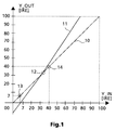
- Fig. 1 This process is shown in Fig. 1. Therein, the effect of the transfer function is shown. In the x-direction of the shown graph the input luminance values Y_IN are depicted. In the y-direction of the shown graph the output luminance values are shown. In both cases the luminance values are given in IRE (institute of radio engineers) units which is an often used unit in the field of video signal processing.
- IRE institute of radio engineers
- a dual segment transfer function with an adaptive pivot point is used, see reference number 11.
- the two segments may have different slopes and the adaptive pivot point 12 is the point of intersection of the two segment lines.
- the parameters of the dual segment transfer function are the two slope values of both segments (hereafter called segment gain value) and the location of the pivot point 12.
- segment gain value the two slope values of both segments
- the lower segment is for dark samples and the upper segment for light samples.
- the gain of the lower segment is adaptive to the dark sample distribution. A higher gain results from fewer dark samples and a lower gain from a higher number of dark samples. The gain is limited in the range as given below: 1.0 ⁇ Segment 1 _Gain ⁇ Max_Gain 1
- Max_Gain1 is the value 1.5.
- the gain of the upper segment is adaptive to the frame peak value. It is computed in the way that the detected peak value lower than the nominal, will be moved in the direction of the nominal peak value. If the detected peak value is equal or higher than the nominal peak value than a gain of 1.0 is used (no change). The computed theoretical gain is limited then to a maximum value in order to avoid unnatural effects. 1.0 ⁇ Segment 2_ Gain ⁇ Max _ Gain 2
- Max _ Gain2 is the value 1.7.
- the third parameter of the transfer function is the pivot point. It is adaptive to the average image brightness and allows to make dark pictures contrasty and light. Low average brightness moves the pivot point to lower and high average brightness to higher level.
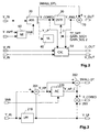
- Fig. 2 shows the top level block diagram of this apparatus. It consists of 5 main blocks adaptive signal splitter 20, transfer function adaptation unit 30, image analysis unit 40, colour saturation unit 50 and noise estimator 60.
- Four input signals are supplied to the apparatus.
- Luminance signal Y_IN of the video signal luminance signal Y_INPF from the previous field and the chrominance signals U_IN and V_IN. From these signals three output signals are generated. These are a modified luminance signal Y_OUT, and modified chrominance signals U_OUT and V_OUT. These signals may be used for further processing or displaying.
- the adaptive signal splitter consists of the main parts low pass filter 210 and adaptive coring unit 220.
- This block prepares the luminance signal adaptive to the signal to noise ratio of the luminance signal and provides the three different signals SMALL_DTL, Y_CORED and Y_LP needed for future processing.
- the luminance signal Y_IN is filtered with a low pass filter 210.
- the low pass filtered signal Y_LP is provided for the use in the image analysis unit 40 as shown in Fig. 2.
- the high pass component of the luminance signal is generated simply by subtracting the low pass filtered signal Y_LP from the incoming signal Y_IN in adder 201.
- the high pass signal Y_HP is applied to the adaptive coring unit 220 where the noise and detail signals below the coring level are removed.
- the coring level is determined by an estimate of the signal to noise ratio SNR provided from block 60 in Fig. 2.
- the output signal Y_HP_C of the adaptive coring unit 220 is added to the low pass signal Y_LP in adder 203.
- the result is a noise reduced signal Y_CORED. This signal is provided to the transfer function unit 30 for further processing.
- the coring function does not distinguish between noise and image signals, a sharpness loss will be caused due to the omission of high frequency small amplitude image signals. Therefore, the signal amount SMALL_DTL cut by the coring unit 220, is added to the processed signal Y_PWL after the whole DCI-processing again, see Fig. 2. This procedure allows to reduce the noise amplification without a loss of small detail signals.
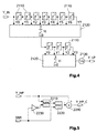
- the structure of the low pass filter is shown in Fig. 4 Its a common low pass filter structure.
- reference number 2110 denotes delay units
- reference number 2120 denotes summation stages
- reference number 2130 denotes a division stage.
- the low pass filter has a -3 dB frequency limit at about 700 kHz.
- the structure of the adaptive coring unit 220 is shown in Fig. 5.
- reference number 2210 denotes a minimum value selector and reference number 2220 denotes a maximum value selector.
- Reference number 2230 denotes an inverting unit which performs a multiplication with the factor -1 and reference number 2240 an adder.
- the function of the adaptive coring unit 220 is shown self explanatory in Fig. 5.
- the basic function of the dynamic contrast improvement process DCI is to analyse the picture framewise in real time and adjust the parameters of a dual segment transfer function depending on the analysis results for the best subjective picture quality.
- Each image frame is analysed for three different characteristics.
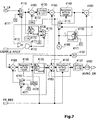
- a block diagram of the image analysis unit 40 is shown in Fig. 6.
- Reference numbers 410, 420, 430 denotes an average brightness analysis unit, a dark sample distribution analysis unit and a frame peak analysis unit.
- the output results of these units are processed in a IIR. filtering and parameter computation unit 450. After the processing in this unit the parameters of the dual segment transfer function are achieved and they are applied to the next frame not to the current frame because a filtering is necessary anyhow and an instantaneous reaction on small temporal variations is unwanted.
- the picture format may be changed in applications like zooming or when a different picture format like letterbox format is received.
- a letterbox transmission is received, not all areas of the display include active video portions.
- zooming applications it is often the case that not all active video lines are displayed. Therefore care must be taken, that the image analysis function is not falsified by inactive portions or portions which are not displayed.
- an analysis window is defined in analysis window unit 440.
- the analysis window defines a part within the displayed picture size for analysis.
- the analysis for DCI functions is enabled within the window and disabled outside the window. In this way it is also possible to disable the analysis in subtitles and logos.
- the analysis window may be defined by user setting W_US or automatically by a unit which detects the picture format and size W_PFS.
- the pivot point of the dual segment transfer function is adaptive to the average image brightness value. It is moved to lower values for dark pictures (having low average brightness values) and it is moved to higher values for light pictures (having higher average brightness values). The analysis is done as shown in Fig. 7.
- the analysis is done framewise and only for samples within the analysis window.
- the register 4160 contains the information about the average image brightness.
- the result is limited in limiter 4120 according to the given range and divided by 2 in division stage 4182.
- the final average brightness information determines the position of the transfer function pivot point. All the registers are reset by the frame reset pulse before the analysis for the next frame starts.
- the register 4230 counts the total sample number. It's value is increased for every sample inside the analysis window by the value of one. It is reset to zero and a carryover of one is added to register 4220 if the counted sample number is equal to the parameter value SENS.
- the analysis is done framewise only for samples within the analysis window.
- the register 4220 contains information about the dark sample distribution and determines the segment gain of the lower segment of the dual segment transfer function. Also here, all the registers are reset before the analysis for the next frame starts.
- the maximum frame peak value is detected by the circuit disclosed in Fig. 9. Each time, the maximum value is stored in register 4310. The detected frame peak value is limited to a certain range so that the segment gain, which is computed in another block, never goes below the value 1.0 and never exceeds a predefined maximum value. The frame peak value determines the gain of the second segment of the dual segment transfer function as will be explained later on.
- the image analysis unit provides information for each frame about the average brightness, dark sample distribution and frame peak value. These values determine the characteristic of the transfer function used for the next frame. All these three values are filtered with an IIR filter (Infinite Impulse Response Filter) and stored framewise.
- the filter time constants are determined by the user settings AB_FC for average brightness values, DS_FC for dark sample distribution values and PK_FC for peak values in respective variable memories 4540, 4541 and 4542.
- a multiplex control signal MUX_CTRL switches the corresponding multiplexers 4510. All the computations in the filtering and parameter computation unit 450 are done within the vertical blanking time.
- the filtered values are used to compute the parameters of the dual segment transfer function.
- the filtered average brightness information is divided by 4 and then subtracted from a constant value of 106.
- the result is the pivot point value (TF_DPP).
- the filtered dark sample distribution value provides the gain for the first segment (lower segment) of the dual segment transfer function, also after division by 4 in bit shifter 4570. An additional processing is necessary in order to get the gain for the second segment (upper segment), derived from the filtered peak value.
- the gain is computed so that the filtered peak values, lower than 100 IRE, are transferred to 100 IRE.
- the detected peak value has been limited in frame peak analysis unit 430 to a certain range so that the segment gain never goes below 1.0 and never exceeds a predefined maximum value, e.g. 1.7.
- the maximum gain is defined in respect to preserving natural picture quality.
- GAIN _ SEG 2 Y 100 IRE - TF _ DPP FR _ PEAK _ FILT - TF _ DPP
- the computation of the segment gain according to this equation requires a division operation. That can be done with a multiplier 4581 and a lookup table 4550.
- the look-up table contains the results of 1 FR _ PEAK _ FILT - TF _ DPP with a precision of n bits, as given in table below:
- X FR _ PEAK _ FILT - TF _ DPP
- X min FR _ PEAK _ FILT min - TF _ DPP max
- the computed parameters TF_DPP, GAIN_SEG1_FRC and GAIN_SEG2_FRC determine the transfer function dynamic pivot point, fraction part of segment gain 1 and fraction part of segment gain2. They are supplied to the dual segment transfer function unit. The computation has to be completed at latest before the first active data of the next frame. The parameters are frozen during the flow of active data of the frame .
- the dynamic contrast improvement video processing is based mainly on the dual segment transfer function.
- the parameters are provided from the common IIR filter and parameter computation unit 450.
- the DCI processing can be switched on and off by the user setting parameter DCI_ON. It is switched off during the horizontal and vertical blanking time via composite blanking signal COMP_BLANK.
- a hardware implementation of these calculations is shown in Fig. 11 in a self explanatory manner.
- the expression 1/(Y_CORED-Y bl ) is approximated by a look-up table 520.
- the gain value results from the product of ( Y_DSTF-Y bl )*(1/(Y_CORED-Y bl ) ).
- the colour saturation compensation is only done for desaturated colours.
- the desaturation occurs in the second segment from the pivot point up to 100 IRE.
- the colour saturation can only be increased. A compensation in this area would fade the colours.
- the maximum allowed colour compensation gain is computed for each chrominance sample with the components absolute value calculator 561, maximum selector 530, limiter 512, adder 570, constant memory 553, look-up table 521 and bit shifter 541.
- the colour saturation compensation gain is limited by using the look up table 521 if it is higher than the allowed value so that a perceptible tint error is avoided.
- the coring threshold SNR used in the adaptive signal splitter part determines the amount of high frequency small signal amplitude suppression in the processed luminance signal. It is desirable to have for low noise video material small coring levels and for noisy video material large coring levels. The system performance can be optimised by controlling the coring levels depending on the noise level in the video material. The noise is measured by the noise estimator 60.
- the new dynamic contrast improvement method and apparatus will be mainly used in video display devices like direct view TV sets or projection TV sets. In plasma and LCD display applications its use brings the best benefit.
Abstract
A method and apparatus for dynamic contrast improvement in
video pictures is proposed. There is a strong demand for
picture contrast but each video display has a limited
dynamic range. The picture contrast can't be increased by
simply increasing the video signal amplitude because
exceeding the display dynamic range in some video scenes
causes unwanted disturbing effects.
According to the basic solution of the invention the video
pictures are analysed framewise in real time and the
parameters of a transfer function for contrast improvement
are adjusted depending on the analysis results for the best
subjective picture quality.
Description
- The invention relates to a method and apparatus for dynamic contrast improvement of video pictures.
- In the field of video display design there is a strong demand for picture contrast but each video display has a limited dynamic range. Especially the flat display panels like LCD and plasma displays have a lower dynamic range compared to the CRT displays. The picture contrast can't be increased by simply increasing the video signal amplitude because exceeding the display dynamic range causes unwanted disturbing effects.
- It is an object of the invention to disclose a method and an apparatus which makes efficient use of the display dynamic range to increase the picture contrast and quality.
This object is achieved by the measures claimed in claims 1 and 10. According to the claimed solution in claim 1 the picture contrast is optimised by analysing the picture contents of the displayed video pictures and adjusting the contrast dependent on the results of the picture content analysis step. More specifically, the basic solution according to the invention is to analyse the video pictures framewise in real time and adjust the parameters of a transfer function for contrast improvement depending on the analysis results for the best subjective picture quality. - Advantageous additional embodiments of the inventive method are disclosed in the respective dependent claims. It has been found that the use of a dual segment transfer function gives good results. The preferred dual segment transfer function which is used in the embodiment according to claim 2 consists of two segments with an adaptive pivot point which separates the two segments. A lower segment for dark samples and an upper segment for light samples.
- According to claim 3 each image frame is analysed for different characteristics. The image average brightness, the dark sample distribution and the frame peak value. In a preferred embodiment all the three parameters are used to adjust the transfer function.
- The gain of the lower segment is adaptive to the dark sample distribution (see claim 5). A higher gain results from fewer dark samples and a lower gain from a higher number of dark samples. The gain of the upper segment is adaptive to the frame peak value (see claim 6). It is computed in the way that the detected peak value lower than the nominal peak value for full contrast, will be moved to the nominal peak value. If the detected peak value is equal or higher than the nominal peak value then a gain of 1.0 is used (no change). In the other direction the computed theoretical gain is limited to a maximum value in order to avoid unnatural effects.
- The third parameter of the transfer function is the pivot point. It is adaptive to the average image brightness and allows to make dark pictures lighter and increase the contrast (see claim 7). Low average brightness values move the pivot point to lower and high average brightness values to higher levels (see claim 8)
- In order to smooth the results of the contrast improvement method, the values of the image analysis unit, i.e. average image brightness, dark sample distribution and frame peak value are filtered preferably with an IIR filter.
- According to the claimed solution in claim 10 the inventive apparatus comprises an image analysis unit in which the video pictures are analysed regarding to their picture content and a transfer function adaptation unit in which the parameters of the transfer function for contrast improvement are adapted based on the results achieved in the image analysis unit.
- Advantageous additional embodiments of the inventive apparatus are disclosed in the respective dependent claims.
- For preparation of the luminance signal adaptive to the signal to noise ratio of the video signal, an adaptive signal splitter is provided in which a noise reduced luminance signal is generated to which the transfer function is applied afterwards (see claim 11).
- According to claim 12 the adaptive signal splitter comprises a low pass filter in which the luminance signal is filtered and the low pass component of the signal is fed to the image analysis unit. The low pass filtered signal is used for image analysis in order to reduce the noise influence.
- In a more specific embodiment of the inventive apparatus according to claim 13 the adaptive signal splitter comprises an adaptive coring unit wherein the high pass component of the luminance signal is reduced from noise and small detail signal components adaptive to an estimate of the signal to noise ratio of the luminance signal by applying a corresponding coring level to the high pass component. To this noise reduced signal component is the low pass component signal added, thus providing the noise reduced luminance signal named in claim 11.
- A further improvement can be achieved with the measures disclosed in claim 14. Adding the noise and small details enclosing signal component which has been cut by the adaptive coring unit to the resulting output signal after applying the transfer function allows for a reduction of the noise amplification without a loss of small detail signals. Since the coring function does not distinguish between noise and image signals, a sharpness loss would have been caused otherwise due to the missing of high frequency small amplitude signal components.
- In order to compensate for the effect of the processing of the luminance component on the colour saturation it is advantageous to provide a colour saturation compensation unit which processes the chrominance signals accordingly to compensate for this effect.
- Exemplary embodiments of the invention are illustrated in the drawings and are explained in more detail in the following description. In the figures:
- Figure 1
- shows a graph with a dual segment transfer function used for contrast improvement;
- Figure 2
- shows a top level block diagram of the apparatus for dynamic contrast improvement;
- Figure 3
- shows a block diagram of an adaptive signal splitter;
- Figure 4
- shows a block diagram of a low pass filter used in the adaptive signal splitter;
- Figure 5
- shows a block diagram of an adaptive coring unit used in the adaptive signal splitter;
- Figure 6
- shows a block diagram of an image analysis unit;
- Figure 7
- shows a block diagram of an average brightness analysis unit included in the image analysis unit;
- Figure 8
- shows a block diagram of a dark sample distribution analysis unit included in the image analysis unit;
- Figure 9
- shows a block diagram of a frame peak analysis unit included in the image analysis unit;
- Figure 10
- shows a block diagram of an IIR filter unit and a parameter computation unit included in the image analysis unit;
- Figure 11
- shows a block diagram of a transfer function adaptation unit and
- Figure 12
- shows a block diagram of a colour saturation compensation unit;
- The basic function of the dynamic contrast improvement method DCI according to the invention is to analyse the picture framewise in real time and adjust the parameters of a transfer function depending on the analysis results for the best subjective picture quality. As the luminance signal component of a video signal determines mainly the picture contrast, the new dynamic contrast improvement method applies only the luminance signal to the transfer function which assigns to each luminance signal point (pixel of the video picture) an output value thus resulting in improved picture contrast and quality.
- This process is shown in Fig. 1. Therein, the effect of the transfer function is shown. In the x-direction of the shown graph the input luminance values Y_IN are depicted. In the y-direction of the shown graph the output luminance values are shown. In both cases the luminance values are given in IRE (institute of radio engineers) units which is an often used unit in the field of video signal processing. A luminance signal with 100 IRE represents the white level of a standard video signal and a luminance signal with 0 IRE represents the black level of a standard video signal.
- For the different kinds of displays special adjustments are available so that for a standard video signal test pattern the optimum black and white colours are reproduced. When in video films e.g. dark scenes occur, the displayed video pictures may have low contrast values irrespective of the special adjustments and the pictures seem to be unclear or foggy or the like. So, there is a strong demand of dynamic contrast improvement. When no contrast improvement is made, the transfer function will have the form of a straight line with slope 1, see reference number 10 in Fig. 1.
- According to the invention a dual segment transfer function with an adaptive pivot point is used, see reference number 11. The two segments may have different slopes and the adaptive pivot point 12 is the point of intersection of the two segment lines. The parameters of the dual segment transfer function are the two slope values of both segments (hereafter called segment gain value) and the location of the pivot point 12. The lower segment is for dark samples and the upper segment for light samples.
- The gain of the lower segment is adaptive to the dark sample distribution. A higher gain results from fewer dark samples and a lower gain from a higher number of dark samples. The gain is limited in the range as given below:
- In a preferred embodiment of the invention Max_Gain1 is the value 1.5.
- The gain of the upper segment is adaptive to the frame peak value. It is computed in the way that the detected peak value lower than the nominal, will be moved in the direction of the nominal peak value. If the detected peak value is equal or higher than the nominal peak value than a gain of 1.0 is used (no change). The computed theoretical gain is limited then to a maximum value in order to avoid unnatural effects.
- In a preferred embodiment of the invention Max_Gain2 is the value 1.7.
- The third parameter of the transfer function is the pivot point. It is adaptive to the average image brightness and allows to make dark pictures contrasty and light. Low average brightness moves the pivot point to lower and high average brightness to higher level. In Fig. 1 it is shown that for ease of implementation the pivot point always lies on the straight line 10 and the lowest possible location is the point (x=7 IRE, y=7 IRE) and the highest possible location is the point (x=40 IRE, y=40 IRE), see reference signs 13 and 14.
- Hereinafter, the apparatus for dynamic contrast improvement according to the invention is explained in detail. Fig. 2 shows the top level block diagram of this apparatus. It consists of 5 main blocks adaptive signal splitter 20, transfer function adaptation unit 30, image analysis unit 40, colour saturation unit 50 and noise estimator 60. Four input signals are supplied to the apparatus. Luminance signal Y_IN of the video signal, luminance signal Y_INPF from the previous field and the chrominance signals U_IN and V_IN. From these signals three output signals are generated. These are a modified luminance signal Y_OUT, and modified chrominance signals U_OUT and V_OUT. These signals may be used for further processing or displaying.
- Next the function of the adaptive signal splitter is explained. It consists of the main parts low pass filter 210 and adaptive coring unit 220. This block prepares the luminance signal adaptive to the signal to noise ratio of the luminance signal and provides the three different signals SMALL_DTL, Y_CORED and Y_LP needed for future processing. As shown in Fig. 3, the luminance signal Y_IN is filtered with a low pass filter 210. The low pass filtered signal Y_LP is provided for the use in the image analysis unit 40 as shown in Fig. 2. The high pass component of the luminance signal is generated simply by subtracting the low pass filtered signal Y_LP from the incoming signal Y_IN in adder 201. The high pass signal Y_HP is applied to the adaptive coring unit 220 where the noise and detail signals below the coring level are removed. The coring level is determined by an estimate of the signal to noise ratio SNR provided from block 60 in Fig. 2. The output signal Y_HP_C of the adaptive coring unit 220 is added to the low pass signal Y_LP in adder 203. The result is a noise reduced signal Y_CORED. This signal is provided to the transfer function unit 30 for further processing.
- Since the coring function does not distinguish between noise and image signals, a sharpness loss will be caused due to the omission of high frequency small amplitude image signals. Therefore, the signal amount SMALL_DTL cut by the coring unit 220, is added to the processed signal Y_PWL after the whole DCI-processing again, see Fig. 2. This procedure allows to reduce the noise amplification without a loss of small detail signals.
- The structure of the low pass filter is shown in Fig. 4 Its a common low pass filter structure. Therein, reference number 2110 denotes delay units, reference number 2120 denotes summation stages and reference number 2130 denotes a division stage. The low pass filter has a -3 dB frequency limit at about 700 kHz.
- The structure of the adaptive coring unit 220 is shown in Fig. 5. Therein reference number 2210 denotes a minimum value selector and reference number 2220 denotes a maximum value selector. Reference number 2230 denotes an inverting unit which performs a multiplication with the factor -1 and reference number 2240 an adder. The function of the adaptive coring unit 220 is shown self explanatory in Fig. 5.
- Next, the image analysis unit 40 is explained in greater detail. The basic function of the dynamic contrast improvement process DCI is to analyse the picture framewise in real time and adjust the parameters of a dual segment transfer function depending on the analysis results for the best subjective picture quality. Each image frame is analysed for three different characteristics. The image average brightness, the dark sample distribution and the frame peak value. A block diagram of the image analysis unit 40 is shown in Fig. 6. Reference numbers 410, 420, 430 denotes an average brightness analysis unit, a dark sample distribution analysis unit and a frame peak analysis unit. The output results of these units are processed in a IIR. filtering and parameter computation unit 450. After the processing in this unit the parameters of the dual segment transfer function are achieved and they are applied to the next frame not to the current frame because a filtering is necessary anyhow and an instantaneous reaction on small temporal variations is unwanted.
- In TV sets, the picture format may be changed in applications like zooming or when a different picture format like letterbox format is received. When a letterbox transmission is received, not all areas of the display include active video portions. In zooming applications it is often the case that not all active video lines are displayed. Therefore care must be taken, that the image analysis function is not falsified by inactive portions or portions which are not displayed. For this purpose an analysis window is defined in analysis window unit 440. The analysis window defines a part within the displayed picture size for analysis. The analysis for DCI functions is enabled within the window and disabled outside the window. In this way it is also possible to disable the analysis in subtitles and logos. The analysis window may be defined by user setting W_US or automatically by a unit which detects the picture format and size W_PFS.
- Next the average brightness analysis unit 410 is described in detail. The pivot point of the dual segment transfer function is adaptive to the average image brightness value. It is moved to lower values for dark pictures (having low average brightness values) and it is moved to higher values for light pictures (having higher average brightness values). The analysis is done as shown in Fig. 7.
- All samples below the dark level threshold value =114 in constant memory 4173 are considered as dark samples. The register 4150 is increased by one for every such a sample. When the register value is equal to the parameter value SENS in variable memory 4170 then it is reset and a carryover of one is added to the average register 4160.
- All samples higher than a light level threshold value =106 stored in constant memory 4172 are considered as light samples but they are not simply counted like the dark samples. The sample values of them are also taken into consideration for analysis. The register 4140 is increased by a value of
- The reason for using two difference thresholds for decision between dark and light samples is the desired soft transition. Both threshold values =114 and =106 overlap in a small range called transition range. All the samples within the transition range are considered by both dark and light sample counters represented by registers 4150 and 4140. The average brightness analysis function can be described by equation given below:
- tsn :
- total sample number within analysis window
- pdark:
- dark sample number related to tsn
- pi :
- light sample number, with a value i of i=limit( (sample-threshold),0,127), related to tsn
- SENS :
- parameter; determines the sensitivity
- K :
- parameter; weighting factor
- The analysis is done framewise and only for samples within the analysis window. At the end of this analysis the register 4160 contains the information about the average image brightness. The result is limited in limiter 4120 according to the given range and divided by 2 in division stage 4182. The final average brightness information determines the position of the transfer function pivot point. All the registers are reset by the frame reset pulse before the analysis for the next frame starts.
- Now the function of the dark sample distribution analysis unit 420 is explained by referring to Fig. 8. The amplitude range from 0 IRE up to about 18 IRE is quantized in 5 steps for dark sample distribution analysis. Samples with amplitude values up to 18 IRE are considered as dark samples. Their quantized values are counted in register 4210 as long as the register value is lower than the parameter value SENS in constant memory 4270. If the register value is equal or higher than the parameter value SENS then it is updated by a value calculated according to the below given formula:
- The analysis is done framewise only for samples within the analysis window. At the end of this analysis the register 4220 contains information about the dark sample distribution and determines the segment gain of the lower segment of the dual segment transfer function. Also here, all the registers are reset before the analysis for the next frame starts.
- Next the function of the frame peak analysis unit 430 is explained by referring to Fig. 9. The maximum frame peak value is detected by the circuit disclosed in Fig. 9. Each time, the maximum value is stored in register 4310. The detected frame peak value is limited to a certain range so that the segment gain, which is computed in another block, never goes below the value 1.0 and never exceeds a predefined maximum value. The frame peak value determines the gain of the second segment of the dual segment transfer function as will be explained later on.
- The image analysis unit provides information for each frame about the average brightness, dark sample distribution and frame peak value. These values determine the characteristic of the transfer function used for the next frame. All these three values are filtered with an IIR filter (Infinite Impulse Response Filter) and stored framewise. The filter unit is denoted with the reference sign 4520 in Fig. 10. It consists of multipliers 4521, bit shifters 4522 and 4523 which divide the input samples by the factors 22=4 and 24=16 respectively, adders 4524 and constant memory 4543. The filter time constants are determined by the user settings AB_FC for average brightness values, DS_FC for dark sample distribution values and PK_FC for peak values in respective variable memories 4540, 4541 and 4542. The filtering of all three image analysis values is done in time multiplexed fashion with the same hardware as shown in Fig. 10. A multiplex control signal MUX_CTRL switches the corresponding multiplexers 4510. All the computations in the filtering and parameter computation unit 450 are done within the vertical blanking time.
- The filtered values are used to compute the parameters of the dual segment transfer function. The filtered average brightness information is divided by 4 and then subtracted from a constant value of 106. The result is the pivot point value (TF_DPP). The filtered dark sample distribution value provides the gain for the first segment (lower segment) of the dual segment transfer function, also after division by 4 in bit shifter 4570. An additional processing is necessary in order to get the gain for the second segment (upper segment), derived from the filtered peak value. The gain is computed so that the filtered peak values, lower than 100 IRE, are transferred to 100 IRE. As explained above, the detected peak value has been limited in frame peak analysis unit 430 to a certain range so that the segment gain never goes below 1.0 and never exceeds a predefined maximum value, e.g. 1.7. The maximum gain is defined in respect to preserving natural picture quality. These conditions are expressed in mathematical form below:
- The gain is determined, as given in equation below, by the filtered peak value and the pivot point position.
- Therein, the variables stand for:
- GAIN_SEG2 :
- Segment-2 gain for dual segment transfer function
- Y100IRE :
- Luminance signal 100 IRE value
- TF_DPP :
- Transfer function pivot point value
- FR_PEAK_FILT :
- Filtered luminance peak value
- The computation of the segment gain according to this equation requires a division operation. That can be done with a multiplier 4581 and a lookup table 4550. The look-up table contains the results of
X=FR_PEAK_FILT-TF_DPP ROM_Address=X-Xmin ROM_Value=2 n /X for n = 14 79 0 207 80 1 204 81 2 202 . . . . . . 206 127 79 207 128 79 208 129 78 - The transfer function segment for luminance signals higher than the pivot point is given by the equation
- Yout :
- Output luminance signal
- Yin :
- Input luminance signal.
- When the segment gain is split into integer and fraction part wherein the integer part is always 1, the following formulas apply:
- Using only the fraction part saves one bit. Therefore, the integer part is subtracted from the computed gain. The result is written into the register 4533. The computed parameters TF_DPP, GAIN_SEG1_FRC and GAIN_SEG2_FRC, determine the transfer function dynamic pivot point, fraction part of segment gain 1 and fraction part of segment gain2. They are supplied to the dual segment transfer function unit. The computation has to be completed at latest before the first active data of the next frame. The parameters are frozen during the flow of active data of the frame .
- Next the transfer function unit 30 is explained in detail with reference to Fig. 11.
- The dynamic contrast improvement video processing is based mainly on the dual segment transfer function. The parameters are provided from the common IIR filter and parameter computation unit 450. The application of the dual segment transfer function can be easily expressed with the following mathematical expressions:
- Y_CORED :
- Input signal
- Y_DSTF :
- Output signal
- TF_DPP :
- Transfer function dynamic pivot point
- GAIN_SEG1_FRC :
- Fraction part of first segment (lower segment) gain
- GAIN_SEG2_FRC :
- Fraction part of second segment (upper segment) gain
- The DCI processing can be switched on and off by the user setting parameter DCI_ON. It is switched off during the horizontal and vertical blanking time via composite blanking signal COMP_BLANK. A hardware implementation of these calculations is shown in Fig. 11 in a self explanatory manner.
- Due to the non linear luminance processing in the transfer function unit the colour saturation is changed. This effect is compensated by multiplication of chrominance samples with a compensation gain. This is done in colour saturation compensation unit 50 which is shown in detail in Fig. 12. The basic function of this unit is expressed in the following formula:
- Y_CORED :
- Input luminance value of dual segment transfer function
- Y_DSTF :
- Output luminance value of dual segment transfer function
- Ybl :
- Black level.
- The expression
- The colour saturation compensation is only done for desaturated colours. The desaturation occurs in the second segment from the pivot point up to 100 IRE. In the first segment from 0 IRE up to the pivot point the colour saturation can only be increased. A compensation in this area would fade the colours.
- The contents of the look-up table can be given by the following expressions:
X=Y_CORED-Ybl ROM_Address=X-Xmin ROM_Value=(2n)/X for n=13 17 0 481 18 1 455 19 2 431 236 219 34 237 220 34 238 221 34 - In seldom cases the compensated chrominance component values can exceed the maximum range representable with the given number of bits. Therefore, the maximum allowed colour compensation gain is computed for each chrominance sample with the components absolute value calculator 561, maximum selector 530, limiter 512, adder 570, constant memory 553, look-up table 521 and bit shifter 541. The colour saturation compensation gain is limited by using the look up table 521 if it is higher than the allowed value so that a perceptible tint error is avoided.
- Next, some details concerning the noise estimator 60 are explained. The coring threshold SNR used in the adaptive signal splitter part determines the amount of high frequency small signal amplitude suppression in the processed luminance signal. It is desirable to have for low noise video material small coring levels and for noisy video material large coring levels. The system performance can be optimised by controlling the coring levels depending on the noise level in the video material. The noise is measured by the noise estimator 60.
- The noise estimator estimates the noise level in the active portion of the video signal. Normally in each picture there are small blocks with minimum change of video contents. These blocks are suitable for noise measurement. The pixels of successive fields representing nearly the same spatial location are normally highly correlated and the absolute difference provides a noise information. Due to the statistical variation of noise an averaging of noise levels is necessary. Each filed is subdivided into small blocks of 64 pixels. The absolute difference of pixels between successive fields is averaged over each block. The blocks containing spatial and/or temporal changes do not provide the correct noise level. Their consideration would provide a noise level much higher than the present noise. Therefore the block with the minimum noise level is taken for the noise estimation. This is expressed in the formula given below.
- Xpixel :
- Pixel j of current field
- Xpf :
- Pixel j of previous field.
- The new dynamic contrast improvement method and apparatus will be mainly used in video display devices like direct view TV sets or projection TV sets. In plasma and LCD display applications its use brings the best benefit.
- The new dynamic contrast improvement method has been explained in detail with block diagrams for hardware implementations. It goes without saying that instead of the disclosed block diagram corresponding software implementations could be used.
- The invention is not restricted to the disclosed embodiments. Various modifications are possible and are considered to fall within the scope of the claims. E.g. a somewhat total different transfer function than the dual segment transfer function may be used. More specifically the given restrictions concerning the location of the pivot point may be modified. The whole dynamic contrast improvement method and apparatus is adapted to a framewise processing organisation. This could be changed to fieldwise processing organisation.
Claims (16)
- Method for dynamic contrast improvement of video pictures comprising the steps of analysing the video pictures framewise or fieldwise in real time regarding their picture content and adjusting the parameters (TF_DPP, GAIN_SEG1_FRC, GAIN_SEG2_FRC) of a transfer function (11) which determines the amount of alteration of the luminance and/or chrominance signal of the video picture for contrast improvement.
- Method according to claim 1, wherein the transfer function (11) is a dual segment transfer function with an adaptive pivot point (12) which separates the two segments.
- Method according to claim 1 or 2 wherein the picture frames or fields are analysed for one or more of the following characteristics:image average brightnessdark sample distributionframe or field peak value.
- Method according to one of claims 1 to 3, wherein the analysis of the video pictures is done within an analysis window which is preset or adjusted in size dependent on the received picture format.
- Method according to one of claims 3 or 4, wherein the dark sample distribution value (DRKS_DIST) is used to determine the segment gain (GAIN_SEG1_FRC) of the lower segment of the dual segment transfer function.
- Method according to one of claims 3 - 5, wherein the frame/field peak value (FR_PEAK) is used to determine the segment gain (GAIN_SEG2_FRC) of the upper segment of the dual segment transfer function.
- Method according to one of claims 3 - 6, wherein the adaptive pivot point (12) is adapted in dependence on the image average brightness value (AVRG_BR).
- Method according to claim 7, wherein the adaptive pivot point (12) is moved to lower values for dark pictures with relatively low average brightness value and to higher values for light pictures with relatively high average brightness value.
- Method according to one of claims 3 - 8, wherein the image average brightness values (AVRG_BR), the dark sample distribution values (DRKS_DIST) and the frame/field peak values (FR_PEAK) are filtered with an IIR filter (4520).
- Apparatus for dynamic contrast improvement of video pictures comprising an image analysis unit (40) wherein the video pictures are analysed framewise or fieldwise regarding to their picture content and a transfer function adaptation unit (30) wherein the transfer function for the luminance and/or chrominance signal of the video pictures is adapted dependent on the results of the image analysis unit.
- Apparatus according to claim 10, further comprising an adaptive signal splitter (20) in which a noise reduced luminance signal (Y-CORED) is generated which is processed in the transfer function adaptation unit (30).
- Apparatus according to claim 11, wherein the adaptive signal splitter (20) comprises a low pass filter (210), in which the luminance signal (Y_IN) of the video picture is filtered, the low pass component of the luminance signal being fed to the image analysis unit (40).
- Apparatus according to claim 12 further comprising an adaptive coring unit (220) wherein the high pass component (Y_HP) of the luminance signal is reduced from noise and small detail signal components by using an estimate of the signal to-noise ratio of the luminance signal and a corresponding coring level is applied to the high pass component (Y_HP) of the luminance signal.
- Apparatus according to claim 13, wherein the signal component which is cut by the adaptive coring unit (220) is provided at one output (SMALL_DTL) of the adaptive signal splitter (20) and fed to an adder (70) where it is added to the output signal of the transfer function adaptation unit.
- Apparatus according to one of claims 10 to 14, wherein the image analysis unit (40) comprises one or more of the following components:an average brightness analysis unit (410),a dark sample distribution analysis unit (420),a peak analysis unit (430).
- Apparatus according to one of claims 10 to 15 further comprising a color saturation compensation unit (450) which compensates for the color saturation effect due to the none-linear processing of the luminance component in the transfer function adaption unit (30).
Priority Applications (9)
| Application Number | Priority Date | Filing Date | Title |
|---|---|---|---|
| EP98109976A EP0963111A1 (en) | 1998-06-02 | 1998-06-02 | Method and apparatus for dynamic contrast improvement in video pictures |
| EP99109999A EP0963112B1 (en) | 1998-06-02 | 1999-05-21 | Method and apparatus for dynamic contrast improvement in video pictures |
| DE69934439T DE69934439T2 (en) | 1998-06-02 | 1999-05-21 | Method and apparatus for dynamic contrast enhancement in video images |
| DE69916526T DE69916526T2 (en) | 1998-06-02 | 1999-05-21 | Method and device for dynamic contrast enhancement in video images |
| EP03021074A EP1372340B1 (en) | 1998-06-02 | 1999-05-21 | Method and apparatus for dynamic contrast improvement in video pictures |
| CNB2004100012081A CN1303826C (en) | 1998-06-02 | 1999-05-28 | Method and apparatus for dynamic contrast improvement in video pictures |
| CNB991077393A CN1137574C (en) | 1998-06-02 | 1999-05-28 | Method and apparatus for dynamic contrast improvement in video pictures |
| JP15428599A JP4562825B2 (en) | 1998-06-02 | 1999-06-01 | Method and apparatus for improving dynamic contrast of video images |
| US09/324,495 US6285413B1 (en) | 1998-06-02 | 1999-06-02 | Method and apparatus for dynamic contrast improvement in video pictures |
Applications Claiming Priority (1)
| Application Number | Priority Date | Filing Date | Title |
|---|---|---|---|
| EP98109976A EP0963111A1 (en) | 1998-06-02 | 1998-06-02 | Method and apparatus for dynamic contrast improvement in video pictures |
Publications (1)
| Publication Number | Publication Date |
|---|---|
| EP0963111A1 true EP0963111A1 (en) | 1999-12-08 |
Family
ID=8232044
Family Applications (1)
| Application Number | Title | Priority Date | Filing Date |
|---|---|---|---|
| EP98109976A Withdrawn EP0963111A1 (en) | 1998-06-02 | 1998-06-02 | Method and apparatus for dynamic contrast improvement in video pictures |
Country Status (5)
| Country | Link |
|---|---|
| US (1) | US6285413B1 (en) |
| EP (1) | EP0963111A1 (en) |
| JP (1) | JP4562825B2 (en) |
| CN (2) | CN1137574C (en) |
| DE (2) | DE69934439T2 (en) |
Cited By (5)
| Publication number | Priority date | Publication date | Assignee | Title |
|---|---|---|---|---|
| EP1397008A2 (en) * | 2002-08-23 | 2004-03-10 | Samsung Electronics Co., Ltd. | Adaptive contrast and brightness enhancement with color preservation |
| WO2004079651A2 (en) * | 2003-03-03 | 2004-09-16 | Sun Microsystems Inc. | Automatic gain control, brightness compression, and super-intensity samples |
| WO2007036851A2 (en) * | 2005-09-30 | 2007-04-05 | Nxp B.V. | Dynamic softclipping of video levels |
| US7218737B1 (en) * | 2002-08-21 | 2007-05-15 | Silicon Image, Inc. | System and method for an adaptive state machine to control signal filtering in a serial link |
| CN100428330C (en) * | 2004-02-24 | 2008-10-22 | 株式会社日立制作所 | Image display method and apparatus |
Families Citing this family (26)
| Publication number | Priority date | Publication date | Assignee | Title |
|---|---|---|---|---|
| JP2004519921A (en) * | 2001-03-06 | 2004-07-02 | コーニンクレッカ フィリップス エレクトロニクス エヌ ヴィ | Video signal enhancement method and unit and display device using the method |
| KR20050040849A (en) * | 2001-11-01 | 2005-05-03 | 톰슨 라이센싱 에스.에이. | Method for dynamic contrast improvement |
| KR100522607B1 (en) * | 2003-07-15 | 2005-10-19 | 삼성전자주식회사 | Apparatus and method for executing adaptive video signal processing according to noise condition |
| TWI234398B (en) * | 2003-11-20 | 2005-06-11 | Sunplus Technology Co Ltd | Automatic contrast limiting circuit by spatial domain infinite impulse response filter and method thereof |
| US8050512B2 (en) * | 2004-11-16 | 2011-11-01 | Sharp Laboratories Of America, Inc. | High dynamic range images from low dynamic range images |
| US7715645B2 (en) * | 2004-11-17 | 2010-05-11 | Samsung Electronics Co., Ltd. | Methods to estimate noise variance from a video sequence |
| EP1675407A1 (en) * | 2004-12-27 | 2006-06-28 | Robert Bosch Gmbh | Colour separation |
| KR20070079224A (en) * | 2006-02-01 | 2007-08-06 | 삼성전자주식회사 | Coring device, luminance processor comprising the coring device, and methods thereof |
| CN100479494C (en) * | 2006-03-08 | 2009-04-15 | 深圳Tcl新技术有限公司 | Adjusting method for the image quality |
| KR100763239B1 (en) * | 2006-06-27 | 2007-10-04 | 삼성전자주식회사 | Image processing apparatus and method for enhancing visibility of image on display |
| US20080122857A1 (en) * | 2006-11-29 | 2008-05-29 | Chih-Lin Hsuan | Methods and devices for adjusting display characteristic of a video frame according to luminance statistics |
| KR101454609B1 (en) * | 2008-01-18 | 2014-10-27 | 디지털옵틱스 코포레이션 유럽 리미티드 | Image processing method and apparatus |
| CN101599171A (en) * | 2008-06-03 | 2009-12-09 | 宝利微电子系统控股公司 | Auto contrast's Enhancement Method and device |
| CN101340510B (en) * | 2008-08-07 | 2010-06-23 | 中兴通讯股份有限公司 | Method for video enhancement and apparatus thereof |
| CN101340512B (en) * | 2008-08-12 | 2010-06-09 | 中兴通讯股份有限公司 | Video image processing method |
| WO2010022558A1 (en) * | 2008-08-28 | 2010-03-04 | Hong Kong Applied Science and Technology Research Institute Co. Ltd | Digital image enhancement |
| US8264499B1 (en) | 2009-06-02 | 2012-09-11 | Sprint Communications Company L.P. | Enhancing viewability of information presented on a mobile device |
| US8781248B2 (en) * | 2010-01-28 | 2014-07-15 | Stmicroelectronics Asia Pacific Pte. Ltd. | Image details preservation and enhancement |
| KR101937249B1 (en) * | 2012-10-09 | 2019-04-11 | 에스케이 텔레콤주식회사 | Contrast Enhancement Method and Device based on Image Noise Level for Thermal Imaging Camera |
| TWI472989B (en) * | 2012-12-04 | 2015-02-11 | Pixart Imaging Inc | Image adjusting method and optical navigating apparatus utlizing the image adjusting method |
| CN103096087B (en) * | 2013-02-06 | 2015-09-23 | 上海国茂数字技术有限公司 | A kind of image and video coding-decoding method and system |
| CN104299574B (en) * | 2014-11-13 | 2016-11-30 | 中颖电子股份有限公司 | Automatic current limiting method for OLED display drive apparatus |
| WO2017046408A1 (en) * | 2015-09-18 | 2017-03-23 | Thomson Licensing | Determination of a co-located luminance sample of a color component sample, for hdr coding/decoding |
| CN107948554B (en) * | 2017-11-30 | 2021-07-06 | 深圳Tcl新技术有限公司 | Contrast adjusting method for display picture, display and readable storage medium |
| CN109300095A (en) * | 2018-08-27 | 2019-02-01 | 深圳Tcl新技术有限公司 | Image enchancing method, system and computer readable storage medium |
| CN110865856B (en) * | 2018-08-27 | 2022-04-22 | 华为技术有限公司 | Interface element color display method and device |
Citations (8)
| Publication number | Priority date | Publication date | Assignee | Title |
|---|---|---|---|---|
| FR2575885A1 (en) * | 1985-01-04 | 1986-07-11 | Thomson Csf | CONTRAST REINFORCATOR FOR VIDEO IMAGES |
| US4862270A (en) * | 1987-09-29 | 1989-08-29 | Sony Corp. | Circuit for processing a digital signal having a blanking interval |
| EP0454417A2 (en) * | 1990-04-26 | 1991-10-30 | Canon Kabushiki Kaisha | Image signal processing apparatus |
| US5221963A (en) * | 1990-03-31 | 1993-06-22 | Minolta Camera Kabushiki Kaisha | Video camera having a video signal processing apparatus |
| US5422680A (en) * | 1992-05-22 | 1995-06-06 | Thomson Consumer Electronics, Inc. | Non-linear contrast control apparatus with pixel distribution measurement for video display system |
| EP0677959A1 (en) * | 1994-04-15 | 1995-10-18 | Matsushita Electric Industrial Co., Ltd. | Picture information detecting apparatus for a video signal |
| US5517333A (en) * | 1993-02-24 | 1996-05-14 | Matsushita Electric Industrial Co., Ltd. | Gradation correction device and image sensing device therewith for supplying images with good gradation for both front-lit and back-lit objects |
| WO1997033271A1 (en) * | 1996-03-08 | 1997-09-12 | Honeywell Inc. | Signal enhancement system |
Family Cites Families (14)
| Publication number | Priority date | Publication date | Assignee | Title |
|---|---|---|---|---|
| JPS59190787A (en) * | 1983-04-13 | 1984-10-29 | Victor Co Of Japan Ltd | Processing device of color video signal in color image pickup device |
| US5099330A (en) * | 1988-10-28 | 1992-03-24 | Casio Computer Co., Ltd. | Contrast control based on mean and deviation values |
| JP2765272B2 (en) * | 1991-05-31 | 1998-06-11 | 松下電器産業株式会社 | Automatic black expansion controller for luminance signal |
| US5191420A (en) * | 1991-12-16 | 1993-03-02 | Thomson Consumer Electronics, Inc. | Video system with feedback controlled "white stretch" processing and brightness compensation |
| US5162902A (en) * | 1991-12-16 | 1992-11-10 | Thomson Consumer Electronics, Inc. | Non-linear luminance signal processor responsive to average picture level (APL) of displayed image |
| JP2957824B2 (en) * | 1992-11-17 | 1999-10-06 | 三洋電機株式会社 | Tone correction circuit for liquid crystal display |
| JPH06350873A (en) * | 1993-06-08 | 1994-12-22 | Hitachi Ltd | Television receiver |
| JP3334321B2 (en) * | 1994-02-28 | 2002-10-15 | 株式会社島津製作所 | X-ray television equipment |
| JPH08195903A (en) * | 1995-01-13 | 1996-07-30 | Fujitsu Ltd | Video image pickup device |
| US5777590A (en) * | 1995-08-25 | 1998-07-07 | S3, Incorporated | Grayscale shading for liquid crystal display panels |
| JP3130266B2 (en) * | 1996-03-09 | 2001-01-31 | 三星電子株式会社 | Image improvement method and circuit using average separation histogram equalization |
| JP3494815B2 (en) * | 1996-07-29 | 2004-02-09 | 富士通株式会社 | Video imaging device |
| JP2951910B2 (en) * | 1997-03-18 | 1999-09-20 | 松下電器産業株式会社 | Gradation correction device and gradation correction method for imaging device |
| US6075574A (en) * | 1998-05-22 | 2000-06-13 | Ati Technologies, Inc | Method and apparatus for controlling contrast of images |
-
1998
- 1998-06-02 EP EP98109976A patent/EP0963111A1/en not_active Withdrawn
-
1999
- 1999-05-21 DE DE69934439T patent/DE69934439T2/en not_active Expired - Lifetime
- 1999-05-21 DE DE69916526T patent/DE69916526T2/en not_active Expired - Lifetime
- 1999-05-28 CN CNB991077393A patent/CN1137574C/en not_active Expired - Lifetime
- 1999-05-28 CN CNB2004100012081A patent/CN1303826C/en not_active Expired - Lifetime
- 1999-06-01 JP JP15428599A patent/JP4562825B2/en not_active Expired - Lifetime
- 1999-06-02 US US09/324,495 patent/US6285413B1/en not_active Expired - Lifetime
Patent Citations (8)
| Publication number | Priority date | Publication date | Assignee | Title |
|---|---|---|---|---|
| FR2575885A1 (en) * | 1985-01-04 | 1986-07-11 | Thomson Csf | CONTRAST REINFORCATOR FOR VIDEO IMAGES |
| US4862270A (en) * | 1987-09-29 | 1989-08-29 | Sony Corp. | Circuit for processing a digital signal having a blanking interval |
| US5221963A (en) * | 1990-03-31 | 1993-06-22 | Minolta Camera Kabushiki Kaisha | Video camera having a video signal processing apparatus |
| EP0454417A2 (en) * | 1990-04-26 | 1991-10-30 | Canon Kabushiki Kaisha | Image signal processing apparatus |
| US5422680A (en) * | 1992-05-22 | 1995-06-06 | Thomson Consumer Electronics, Inc. | Non-linear contrast control apparatus with pixel distribution measurement for video display system |
| US5517333A (en) * | 1993-02-24 | 1996-05-14 | Matsushita Electric Industrial Co., Ltd. | Gradation correction device and image sensing device therewith for supplying images with good gradation for both front-lit and back-lit objects |
| EP0677959A1 (en) * | 1994-04-15 | 1995-10-18 | Matsushita Electric Industrial Co., Ltd. | Picture information detecting apparatus for a video signal |
| WO1997033271A1 (en) * | 1996-03-08 | 1997-09-12 | Honeywell Inc. | Signal enhancement system |
Cited By (11)
| Publication number | Priority date | Publication date | Assignee | Title |
|---|---|---|---|---|
| US7218737B1 (en) * | 2002-08-21 | 2007-05-15 | Silicon Image, Inc. | System and method for an adaptive state machine to control signal filtering in a serial link |
| EP1397008A2 (en) * | 2002-08-23 | 2004-03-10 | Samsung Electronics Co., Ltd. | Adaptive contrast and brightness enhancement with color preservation |
| EP1397008A3 (en) * | 2002-08-23 | 2005-06-22 | Samsung Electronics Co., Ltd. | Adaptive contrast and brightness enhancement with color preservation |
| US7102695B2 (en) | 2002-08-23 | 2006-09-05 | Samsung Electronics Co., Ltd. | Adaptive contrast and brightness enhancement with color preservation |
| WO2004079651A2 (en) * | 2003-03-03 | 2004-09-16 | Sun Microsystems Inc. | Automatic gain control, brightness compression, and super-intensity samples |
| WO2004079651A3 (en) * | 2003-03-03 | 2005-03-24 | Sun Microsystems Inc | Automatic gain control, brightness compression, and super-intensity samples |
| CN100428330C (en) * | 2004-02-24 | 2008-10-22 | 株式会社日立制作所 | Image display method and apparatus |
| WO2007036851A2 (en) * | 2005-09-30 | 2007-04-05 | Nxp B.V. | Dynamic softclipping of video levels |
| WO2007036851A3 (en) * | 2005-09-30 | 2008-11-20 | Nxp Bv | Dynamic softclipping of video levels |
| CN101406038B (en) * | 2005-09-30 | 2011-02-23 | Nxp股份有限公司 | Dynamic softclipping of video levels |
| US8203574B2 (en) | 2005-09-30 | 2012-06-19 | Nxp B.V. | Dynamic softclipping of video levels |
Also Published As
| Publication number | Publication date |
|---|---|
| JP4562825B2 (en) | 2010-10-13 |
| CN1303826C (en) | 2007-03-07 |
| DE69916526T2 (en) | 2004-09-23 |
| DE69934439T2 (en) | 2007-09-27 |
| CN1137574C (en) | 2004-02-04 |
| US6285413B1 (en) | 2001-09-04 |
| CN1529516A (en) | 2004-09-15 |
| CN1237850A (en) | 1999-12-08 |
| DE69934439D1 (en) | 2007-01-25 |
| JP2000059649A (en) | 2000-02-25 |
| DE69916526D1 (en) | 2004-05-27 |
Similar Documents
| Publication | Publication Date | Title |
|---|---|---|
| EP0963111A1 (en) | Method and apparatus for dynamic contrast improvement in video pictures | |
| EP0963112B1 (en) | Method and apparatus for dynamic contrast improvement in video pictures | |
| EP1137258B1 (en) | Image processing circuit and method for processing image | |
| EP0654943B1 (en) | Image enhancement method and circuit | |
| CA2417169C (en) | Image processing apparatus and image processing method | |
| US6788823B2 (en) | Method and apparatus for reducing motion artifacts and noise in video image processing | |
| KR100322596B1 (en) | Apparatus and method for improving image quality maintaining brightness of input image | |
| US5606375A (en) | Method for enhancing detail in color signals and circuitry for implementing that method in color video equipment | |
| US7903179B2 (en) | Motion detection device and noise reduction device using that | |
| EP1137267A2 (en) | Device and method for image processing | |
| US10841461B2 (en) | Method and apparatus for controlling overshoot in a video enhancement system | |
| US20100259689A1 (en) | Video display apparatus and method, and signal processing circuit and liquid crystal backlight driver to be built therein | |
| JP2003506925A (en) | Method and apparatus for enhancing a video signal | |
| US8189113B2 (en) | Image processing apparatus, video reception apparatus, and image processing method | |
| US6633342B2 (en) | Apparatus and method for compensating image signal | |
| KR20020067929A (en) | Adaptive clipping prevention for picture sharpness enhancement | |
| KR20020022672A (en) | Electronic circuit and method for enhancing an image | |
| US7894686B2 (en) | Adaptive video enhancement gain control | |
| JP4174656B2 (en) | Image display device, image processing device, and image processing method | |
| JP4017810B2 (en) | Gradation correction apparatus and recording medium | |
| JP2935389B2 (en) | Video signal processing device and nonlinear signal processing device | |
| JPH02213283A (en) | Contour emphasis quantity adjusting circuit | |
| EP0268332B1 (en) | Method and apparatus for generating an adaptive peaking signal increasing the sharpness of a video signal | |
| KR100786094B1 (en) | The display device for displaying a screen of enhanced sharpness, and the method for controlling the same | |
| IE20080497U1 (en) | Image processing method and apparatus |
Legal Events
| Date | Code | Title | Description |
|---|---|---|---|
| PUAI | Public reference made under article 153(3) epc to a published international application that has entered the european phase |
Free format text: ORIGINAL CODE: 0009012 |
|
| AK | Designated contracting states |
Kind code of ref document: A1 Designated state(s): AT BE CH CY DE DK ES FI FR GB GR IE IT LI LU MC NL PT SE |
|
| AX | Request for extension of the european patent |
Free format text: AL;LT;LV;MK;RO;SI |
|
| AKX | Designation fees paid | ||
| REG | Reference to a national code |
Ref country code: DE Ref legal event code: 8566 |
|
| STAA | Information on the status of an ep patent application or granted ep patent |
Free format text: STATUS: THE APPLICATION IS DEEMED TO BE WITHDRAWN |
|
| 18D | Application deemed to be withdrawn |
Effective date: 20000609 |