-
The present invention relates to a self-retaining
catheter that is arranged to be retained in a blood
vessel or the like of a patient and to permit a medical
fluid, for example such as a carcinostatic, to be
injected on a periodic basis, and an inserting
apparatus thereof.
-
For administration of such a medical fluid as a
carcinostatic, for example, the medical fluid was
administered into a blood vessel conventionally by use
of an injection syringe or a drip. In that case, the
medical fluid circulated through blood vessels in the
body, and thus there was the fear of damaging the
normal cells in addition to cancerous cells.
-
Under such circumstances, attempts have been made
to achieve such techniques as to percutaneously insert
a catheter into a blood vessel, locate the leading end
of this catheter at an arterial inlet to an organ
affected by cancer, and directly inject the medical
fluid into the organ affected by cancer, thereby
accomplishing a prominent carcinostatic effect even
with a small dose of the medical fluid.
-
In this case, after the catheter was set so that
the leading end thereof was located at the arterial
inlet to the target organ, injection of the medical
fluid was carried out while the base side of the
catheter was fixed to the patient's body so as to
prevent the leading end of the catheter from shifting
from the position.
-
In order to prevent the medical fluid from flowing
into arteries branched to the other normal organs,
embolization coils or the like were inserted into
inlets of the arteries branched to the other normal
organs so as to temporarily obstruct the blood flow, so
that the medical fluid could flow into only the organ
affected by cancer.
-
On the other hand, there are conventionally known
catheters having the structure capable of retaining
themselves not only in the blood vessels, but also in
tubular organs of the human body, and an example of
such catheters is the one described in Japanese Patent
Application Laid-open No. 5-192389, in which the
catheter is comprised of an outside tube, an inside
tube, and a reinforcement interposed between them, and
in which a flap projecting to engage an inner wall of a
tubular organ of the human body is mounted on the
periphery of the leading end of the outside tube.
-
Another known example is the one described in
Japanese Utility Model Application Laid-open No. 5-86355,
in which a plurality of fins are arranged at
intervals on the periphery of the leading end or an
intermediate section of the catheter so as to act as a
cushion, a seal, a stopper, and a protector.
-
In treatments by the conventional method for
locating the leading end of the catheter at the inlet
of the artery to the affected organ as a target and
directly feeding the medical fluid into the target
organ, there sometimes occurred, however, accidents
that the position of the leading end of the catheter
shifted because of a body motion, such as tossing, of
the patient on the occasion of injection of the medical
fluid, so as to cause the medical fluid to flow into
the other organs than the target organ, though the base
side of the catheter was fixed to the patient's body.
-
Further, it was not easy to apply the self-retaining
catheter described in Japanese Patent
Application Laid-open No. 5-192389 to a tubular organ
comprised of a narrow and thin wall, such as a blood
vessel, because the flap projecting from the periphery
of the leading end of the catheter tended to damage the
internal wall of the tubular organ.
-
With the self-retaining catheter described in
Japanese Utility Model Application Laid-open No. 5-86355,
the fins also tended to damage the internal wall
of the tubular organ and in applications to the blood
vessels or the like, it was difficult to retain the
catheter over the long term, because the fins
obstructed the blood flow.
-
An object of the present invention is to provide a
self-retaining catheter whose leading end can be fixed
to an inner wall of a tubular organ such as a blood
vessel, that causes little damage to the inner wall of
the tubular organ during insertion and during
withdrawal, and that causes little obstruction against
the blood flow or the like in the self-retaining state,
and also to provide an inserting apparatus of the self-retaining
catheter.
-
In order to accomplish the above object, a self-retaining
catheter according to the present invention
comprises a tubular catheter body, and an elastic wire
of a winding shape buried in one end portion of the
catheter body, wherein the end portion of the catheter
body with the wire inside is in a winding state.
-
In this structure, when the leading end of the
self-retaining catheter is guided to a target portion
of a tubular organ such as a blood vessel to be
retained there, the catheter body starts to go back
into the winding state because of the wire buried
inside the leading end of the catheter body, whereby
the catheter body is fixed while being elastically
urged against the inner wall of the tubular organ. In
this case there occurs little damage to the inner wall
of the tubular organ, because the catheter body is
fixed while being urged against the inner wall of the
tubular organ by the winding shape of the catheter
body, different from the structures wherein the flap or
fins projecting from the catheter engage the inner wall
of the tubular organ. Since the catheter body is in
the winding state, a clearance is created between the
catheter body and the inner wall of the tubular organ,
so that the catheter does not obstruct the blood flow
or the like.
-
When the self-retaining catheter is withdrawn, a
master catheter is inserted along the periphery of the
self-retaining catheter. Then the self-retaining
catheter is pulled to the base side relative to the
master catheter, so as to retract the self-retaining
catheter into the master catheter while stretching the
leading end of the self-retaining catheter. This
simple operation permits the self-retaining catheter to
be withdrawn, and thus the withdrawal (evulsion) of the
self-retaining catheter can be performed readily.
-
Another embodiment of the self-retaining catheter
according to the present invention comprises a tubular
catheter body, and an elastic wire of a winding shape
greater than an outside diameter of the catheter body,
wherein said wire is connected to one end of the
catheter body so as to project outwardly from the
catheter body.
-
In this structure, when the leading end of the
self-retaining catheter is guided to a target portion
of the tubular organ such as the blood vessel to be
retained there, the wire connected to the leading end
of the catheter body starts to go back into the winding
state, so that the wire becomes fixed while being
elastically urged against the inner wall of the tubular
organ. Therefore, the self-retaining catheter causes
little damage to the inner wall of the tubular organ
and does not obstruct the blood flow or the like, from
the same reasons as described above.
-
The catheter can be constructed in such a
structure that the catheter body linearly extends from
a position in a periphery of the winding shape of the
wire.
-
In this structure, when the leading end of the
catheter body is fixed inside the tubular organ such as
the blood vessel, the base side of the catheter body
extends from the position in the periphery of the
winding shape of the leading end and along the inner
wall of the tubular organ. Therefore, this structure
causes little obstruction to flow of the body fluid
such as the blood flow and can prevent occurrence of a
thrombus or the like.
-
The catheter can be constructed in such a
structure that an aperture for outflow of a medical
fluid is formed in a peripheral wall of the catheter
body near the end where the wire is mounted, the
aperture is formed in a slit shape, the aperture is
opened when a pressure of the fluid inside is applied
thereto, and the aperture is closed when the pressure
of the fluid inside is not applied thereto.
-
In this structure, after the medical fluid flows
in the axial direction inside the catheter body, the
medical fluid changes its direction so as to flow
sideways out of the aperture formed in the peripheral
wall. This restrains the medical fluid from hitting
the inner wall of the tubular organ such as the blood
vessel with strong force and in turn, it can avoid
obstruction of a flow passage or the like due to the
damage to the inner wall of the blood vessel or the
like. Since the aperture is of the slit shape and is
opened only when the pressure of the fluid inside is
applied thereto, the body fluid such as the blood can
be prevented from flowing back through the catheter
during the periods in which the medical fluid is not
injected.
-
In the conventional methods, the medical fluid
introduced into the catheter advanced along the axis of
the catheter and flowed straight out of the leading end
thereof. Thus the conventional methods had the problem
that the medical fluid hit the inner wall of the blood
vessel, the blood vessel absorbed the medical fluid, it
damaged the inner wall of the blood vessel, and it was
likely to cause obstruction in the blood vessel. In
the present invention, where the aperture for outflow
of the medical fluid is formed in the peripheral wall
of the catheter body, the medical fluid is, however,
prevented from directly hitting the inner wall of the
blood vessel or the like with strong force, which can
prevent the obstruction due to the damage to the inner
wall of the blood vessel or the like.
-
The self-retaining catheter can be constructed in
such a structure that an aperture for outflow of the
medical fluid is formed in a peripheral wall of the
catheter body near the end where the wire is mounted
and that the aperture is formed as being directed
toward the center of the winding shape of the wire, in
the peripheral wall of the catheter body.
-
In this structure, where the aperture of the
catheter body is directed toward the center of the
winding shape of the wire, i.e., inwardly inside the
tubular organ, the medical fluid is prevented from
strongly hitting the inner wall of the tubular organ,
because the aperture is directed toward the center of
the tubular organ. Thus there occurs little damage to
the inner wall.
-
The self-retaining catheter can be constructed in
such a structure that a contrast chip is mounted near
the aperture of the catheter body.
-
In this structure, where the contrast chip is
mounted near the aperture of the catheter body, a
position of the medical fluid injection aperture can be
detected with accuracy, and the medical treatment can
be carried out more precisely.
-
A self-retaining catheter inserting apparatus
according to the present invention comprises the self-retaining
catheter according to the present invention,
a core wire arranged to be detachably inserted into the
self-retaining catheter, and a master catheter having
an inside diameter that permits insertion of the self-retaining
catheter.
-
In this structure, the self-retaining catheter can
be guided to a predetermined portion in a tubular organ
through the master catheter, and the self-retaining
catheter can be fixed in the tubular organ by restoring
force of the wire when the leading end of the self-retaining
catheter is made to project out of the master
catheter. In this case, the insertion operation of the
self-retaining catheter can be facilitated with
increase in the stiffness thereof by inserting the core
wire into the self-retaining catheter.
-
Another embodiment of the self-retaining catheter
inserting apparatus according to the present invention
comprises the self-retaining catheter according to the
present invention, a core wire arranged to be
detachably inserted into this self-retaining catheter,
a master catheter having an inside diameter that
permits insertion of the self-retaining catheter, and a
sheath for percutaneous insertion of the master
catheter into a blood vessel.
-
In this structure, the sheath is first
percutaneously inserted into the blood vessel, the
master catheter is then inserted through this sheath,
the leading end of this master catheter is guided to a
desired portion in the blood vessel, and the self-retaining
catheter is inserted through this master
catheter. Therefore, the insertion operation of the
self-retaining catheter into the blood vessel can be
performed surely and readily.
-
A further embodiment of the self-retaining
catheter inserting apparatus according to the present
invention comprises the self-retaining catheter
according to the present invention, a core wire
arranged to be detachably inserted into the self-retaining
catheter, a master catheter having an inside
diameter that permits insertion of the self-retaining
catheter, a sheath for percutaneous insertion of the
master catheter into a blood vessel, and a medical
fluid injection port to be embedded in the body while
being connected to a base end of the self-retaining
catheter.
-
In this structure, the sheath is first
percutaneously inserted into the blood vessel, the
master catheter is then inserted through this sheath,
and the leading end of this master catheter is guided
to a desired portion in the blood vessel. Thereafter
the self-retaining catheter is inserted through the
master catheter, and the leading end of the self-retaining
catheter is made to project out of the master
catheter to be fixed to the inner wall of the blood
vessel. Then the master catheter is drawn out, the
medical fluid injection port is connected to the base
end of the self-retaining catheter, and this medical
fluid injection port is embedded under the skin. By
this structure, an injection needle can be stuck into
the medical fluid injection port when necessary and the
medical fluid can be injected readily into the affected
region of the target, which extremely reduces the load
on the patient.
-
When the self-retaining catheter is withdrawn, the
master catheter is inserted along the periphery of the
self-retaining catheter. Then the self-retaining
catheter is pulled to the base side relative to the
master catheter, so as to retract the self-retaining
catheter into the master catheter while stretching the
leading end of the self-retaining catheter. This
simple operation permits the self-retaining catheter to
be withdrawn, and thus the withdrawal (evulsion) of the
self-retaining catheter can be performed readily.
- Fig. 1 is a partial cutaway side view to show an
embodiment of the self-retaining catheter according to
the present invention;
- Fig. 2 is a partial sectional view to show a
fixing structure of the wire at the leading end of the
self-retaining catheter;
- Fig. 3A, Fig. 3B, and Fig. 3C are partial
sectional views to show other examples of the fixing
structure of the wire;
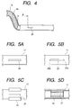
- Fig. 4 is a partial sectional view to show the
vicinity of an aperture through which a medical fluid
in the self-retaining catheter flows out;
- Fig. 5A, Fig. 5B, Fig. 5C, and Fig. 5D are
explanatory drawings to show other examples of the
shape of the aperture;
- Fig. 6 is a perspective view to show the shape of
the leading end of the self-retaining catheter;
- Fig. 7 is a partial sectional view to show the
relation between the wire and the core wire of the
self-retaining catheter;
- Fig. 8 is a partial sectional view to show another
embodiment of the self-retaining catheter according to
the present invention;
- Fig. 9 is a partial sectional view to show still
another embodiment of the self-retaining catheter
according to the present invention;
- Fig. 10 is an explanatory drawing to show a state
in which the self-retaining catheter is being
percutaneously inserted into a blood vessel;
- Fig. 11A, Fig. 11B, Fig. 11C, Fig. 11D, and Fig.
11E are explanatory drawings to show procedures for
inserting the self-retaining catheter into the blood
vessel through the master catheter and allowing the
medical fluid to flow out therethrough;
- Fig. 12 is an explanatory drawing to show a state
in which the leading end of the self-retaining catheter
is fixed at a target portion of a blood vessel;
- Fig. 13 is an explanatory drawing to schematically
show an enlarged state in which the leading end of the
self-retaining catheter is fixed at the target portion
of the blood vessel;
- Fig. 14 is an explanatory drawing to show a state
in which the master catheter is retracted;
- Fig. 15 is a perspective view to show a medical
fluid injection port; and
- Fig. 16 is an explanatory drawing to show a state
in which the medical fluid injection port is embedded
under the skin and in which the medical fluid is
supplied thereto with an injection syringe.
-
-
Fig. 1 illustrates an embodiment of the self-retaining
catheter according to the present invention.
-
This self-retaining catheter 10 has a tubular
catheter body 11, for example, made of a synthetic
resin such as urethane, nylon, polyethylene,
polypropylene, or silicone, or a shape memory alloy, or
the like. A closure 13, which permits a core wire 12
to be inserted in a sealed state into the catheter body
11, is mounted at the base end of the catheter body 11.
The core wire 12 can be selected from wires of shape
memory alloys, stainless steel, or the like, guide
wires, and so on.
-
The inside and/or the outside of the catheter body
is preferably coated with a hydrophilic resin in order
to enhance a sliding property of the core wire 12 to
the catheter body 11 or in order to increase a sliding
property of the catheter body 11 to a master catheter
described hereinafter.
-
A coil wire 14 having higher stiffness than the
catheter body 11 is buried inside the leading end of
the catheter body 11. The wire 14 is made of a shape
memory alloy treated by such a shape memory treatment
as to exhibit superelasticity near body temperatures of
the human body in the case of this embodiment, but the
wire 14 may also be selected from wires of other metals
such as stainless steel, wires of FRP with high
stiffness, and so on. An outside diameter of the coil
wire 14 in a free state is a diameter sufficiently
larger than an inside diameter A of a self-retaining
portion such as an objective blood vessel (see Fig.
11A). In the state in which the coil wire 14 is
interpolated in the catheter body 11, the catheter body
11 is also in a winding shape like a coil having an
outside diameter B larger than the inside diameter A of
the self-retaining portion. Since the wire 14 has
superelasticity while the catheter body 11 is made of a
plastic pipe, they can be elastically deformed, so that
they can be put inside an inside diameter C of the
master catheter 51 (see Fig. 11A). In this state they
can be inserted into a blood vessel or the like. A
ring contrast chip 20 is mounted at the leading end of
the catheter body 11.
-
As shown in Fig. 2, the leading end of the wire 14
is fixed inside the catheter body 11 with an adhesive
15. This prevents the wire 14 from moving inside the
catheter body 11. A distance a between the tip of the
fixing part of wire 14 and the tip of the catheter body
11 is preferably 5-50 mm and most preferably about 20
mm. This range provides the leading end of the
catheter body 11 with flexibility and thus prevents the
leading end from damaging the inner wall of the blood
vessel or the like. The size of the catheter body 11
may be properly determined depending upon an applied
object, but, for example in the case of those for liver
arteries of adults, the outside diameter b is
preferably 0.3-2 mm and the inside diameter c is
preferably 0.1-1.7 mm.
-
Figs. 3A to 3C show other examples of the fixing
structure of the leading end of wire 14.
-
In the example of Fig. 3A, a coil 16 is disposed
around the periphery of the leading end of the wire 14,
and the adhesive 15 is deposited so as to bury the coil
16 and the leading end of the wire 14, whereby the
leading end of the wire 14 is fixed to the catheter
body 11. In this example the coil 16 makes it easier
to deposit the adhesive 15 and reduces the clearance
between the wire 14 and the inner wall of the catheter
body 11, so as to enhance the fixing strength.
-
In the example of Fig. 3B, a contrast chip 17
having a ring shape or a C-shaped cross section is put
inside the catheter body 11, the leading end of the
wire 14 is put in this contrast chip 17, and the
leading end of the wire 14 is fixed by caulking of the
contrast chip 17.
-
In the example of Fig. 3C, a contrast chip 18
having a ring shape or a C-shaped cross section is
mounted on the periphery of the leading end of the
catheter body 11, and the leading end of the wire 14 is
fastened through the catheter body 11 by caulking of
this contrast chip 18.
-
As shown in Fig. 1 and Fig. 4, an aperture 21 of a
slit shape is formed in a peripheral wall a distance d
apart from the base end of the wire 14 in the catheter
body 11 to the base of the catheter body 11. The
length of d is suitably set depending upon an applied
portion, but it is normally 1-15 cm. When a pressure
of a fluid is applied inside, the aperture 21 is opened
as shown by the dotted line in Fig. 4. When the
pressure of the fluid is not applied inside, the
aperture 21 is closed. By this structure, the aperture
is opened on the occasion of injection of a medical
fluid, and during the other periods the body fluid such
as the blood is prevented from flowing through the
aperture 21 into the catheter body 11.
-
In an alternative way, the self-retaining
catheters may be supplied in a selling form without the
aperture 21, and the aperture 21 of the slit shape may
be formed depending upon patient's conditions, for
example by urging the tip of a knife or the like
against the peripheral wall of the catheter body 11 to
cut it immediately before an operation. The aperture
21 can be suitably formed by such working as to cut the
wall with a knife or an edged tool having a fine edge.
If the aperture 21 were made, for example, by machining
with a grinder or the like, a part of the wall would be
lost, so as to form an aperture always open.
Therefore, the valve effect (the effect that the
aperture is opened only when the pressure of the fluid
is applied inside) would not be achieved well.
-
Figs. 5A to 5D show other examples of the
aperture.
-
In the example of Fig. 5A an aperture 22 is formed
in a predetermined width. In the example of Fig. 5B an
aperture 23 is formed in a predetermined width and is
tapered at the both ends 23a, 23b. In the example of
Fig. 5C a contrast chip 19 having a C-shaped cross
section is mounted so as not to cover the aperture 21,
on the periphery of the portion of the catheter body 11
where the aperture 21 is present, whereby the contrast
chip 19 prevents the catheter body 11 from being
crushed in the portion of aperture 21. In the example
of Fig. 5D a contrast chip 19 also having a C-shaped
cross section is set so as not to close the aperture
21, on the inside surface of the portion where the
aperture 21 is formed in the catheter body 11, whereby
the contrast chip 19 prevents the catheter body 11 from
being crushed in that portion.
-
Fig. 6 is a perspective view to show an enlarged
view of the leading end of the self-retaining catheter
10.
-
The leading end of the self-retaining catheter 10
is kept in the winding state of the coil shape by the
wire 14 (not illustrated in Fig. 6) disposed inside the
catheter body 11 as long as no external force is
exerted thereon. The base side of the catheter body 11
linearly extends from a position in a periphery of this
coil winding portion. Because of this shape, when the
self-retaining catheter is set in a tubular organ such
as a blood vessel, the base side of the catheter body
11 extends along the inner wall of the tubular organ
and thus is arranged so as not to be positioned in the
center of the lumen of the tubular organ.
-
The aperture 21 formed in the peripheral wall of
the catheter body 11 is open while being directed in
the direction A toward the center of the coil winding
portion. This allows the aperture 21 to be directed
inwardly of the tubular organ when the catheter is
inserted into the tubular organ such as the blood
vessel. This structure is free of the problem that
when the medical fluid is allowed to flow through the
aperture 21, the medical fluid is ejected strongly
against the intima of the tubular organ to be directly
absorbed through the intima, or the aperture is pushed
against the intima of the tubular organ to interfere
ejection of the medical fluid.
-
While the contrast chip 20 is provided at the
leading end of the catheter body 11, another contrast
chip 20' may also be mounted near the aperture 21 in
place of this contrast chip 20 or together with the
contrast chip 20. This allows the position of the
aperture through which the medical fluid is ejected, to
be detected more accurately. These contrast chips 20,
20' may also be located in the catheter body 11.
-
The aperture 21' may be formed on the inside of
the winding portion of the spiral shape, instead of the
aperture 21 formed in the straight portion of the
catheter body 11. In this case the medical fluid is
introduced through the clearance between the internal
surface of the catheter body 11 and the wire 14 to the
spirally winding portion of the catheter body 11 to
flow out through the aperture 21'.
-
Fig. 7 illustrates the relation between the wire
14 and the core wire 12 in the self-retaining catheter
10. As illustrated, the base end of the wire 14
extends toward the base of the catheter body 11, and
the leading end of the core wire 12 extends toward the
tip of the catheter body 11 and has such a thickness as
to abut against the base end of the wire 14. This
structure allows a pushing force to be occur in the
self-retaining catheter 10 when the core wire 12 is
forced into the catheter body 11.
-
Fig. 8 illustrates another embodiment of the self-retaining
catheter according to the present invention.
Substantially identical portions to those in the
embodiment shown in Fig. 1 will be denoted by the same
reference numerals and the description thereof will be
omitted herein.
-
In the self-retaining catheter 30 of this
embodiment a swirl of wire 32 is put inside the leading
end of the catheter body 11 and the leading end of the
wire 32 is fixed to the catheter body 11 with the
adhesive 15. As a result, the catheter body 11 is kept
in a swirl shape by the stiffness of the wire 32 as
long as no external force is exerted thereon. In the
case of this embodiment the base side of the catheter
body 11 also linearly extends from the periphery of the
swirl winding portion and the aperture 20 is open as
directed toward the center of the winding portion. As
described above, a variety of shapes can be employed
for the winding shape of the wire.
-
Fig. 9 illustrates still another embodiment of the
self-retaining catheter according to the present
invention.
-
In the self-retaining catheter 40 of this
embodiment one end of wire 41 of a coil shape is
connected to the leading end of the catheter body 11
and the wire 41 projects out of the catheter body 11.
The diameter of the coil of wire 41 is larger than the
outside diameter of the catheter body 11 and a contrast
chip 42 is formed at the tip of the wire 41 by melting
the wire in a ball shape or by welding a metal not
transmitting X-rays, such as platinum or a platinum
alloy, to the tip. This contrast chip 42 also presents
the effect of preventing the inner wall of the tubular
organ from being damaged. The outside surface of the
wire 41 is preferably coated with an organism-compatible
resin.
-
The base end of the wire 41 is formed in a small
coil shape, put in the catheter body 11, and fixed
thereto with the adhesive 15. In the case of this
embodiment the base side of the catheter body 11 also
linearly extends from the periphery of the wire 41 of
the coil shape and the aperture 21 formed in the
peripheral wall of the catheter body 11 is open as
being directed to the center of the coil shape of the
wire 41. As in this embodiment, the wire as a fixing
means to the tubular organ may project outwardly from
the catheter body 11.
-
Next, a method for administering a carcinostatic
to liver arteries by use of the self-retaining catheter
10 shown in Fig. 1 will be described referring to Fig.
10 to Fig. 15.
-
Fig. 10 is an explanatory drawing to show a state
in which the self-retaining catheter 10 is
percutaneously inserted into a blood vessel; Figs. 11A
to 11E are explanatory drawings to show procedures for
inserting the self-retaining catheter 10 through the
master catheter into the blood vessel and allowing the
medical fluid to flow out; Fig. 12 is an explanatory
drawing to show a state in which the leading end of the
self-retaining catheter 10 is set at an objective
portion of a blood vessel and fixed there; Fig. 13 is
an explanatory drawing to schematically show an
enlarged state in which the leading end of the self-retaining
catheter 10 is set at the objective portion
of the blood vessel and fixed there; Fig. 14 is an
explanatory drawing to show a state in which the master
catheter is withdrawn; Fig. 15 is a perspective view to
show a medical fluid injection port; Fig. 16 is an
explanatory drawing to show a state in which the
medical fluid injection port is buried under the skin
and in which the medical fluid is supplied thereto with
an injection syringe.
-
In Fig. 10, numeral 51 designates the skin and 52
a blood vessel (the femoral artery in this example).
First, a sheath 53 is percutaneously inserted into the
blood vessel 52 by the known Seldinger method. Then
the master catheter 55 is inserted through a closure 54
provided at the base end of the sheath 53. Further, a
guide wire not illustrated is inserted through a
closure 56 provided at the base end of the master
catheter 55. After the leading end of the guide wire
reaches an objective portion of a blood vessel, the
leading end of the master catheter 55 is forced ahead
along the guide wire up to the aforementioned portion,
and then the guide wire is pulled out.
-
Then the self-retaining catheter 10 is inserted
through the closure 56 provided at the base end of the
master catheter 55 and the core wire 12 is inserted
through the closure 13 provided at the base end of the
self-retaining catheter 10. Then the self-retaining
catheter 10 is forced into the master catheter 55 while
the stiffness is maintained by the core wire 12. For
example, supposing the size of the sheath 53 is 5 Fr
(French size), the size of the master catheter 55 is 4
Fr.
-
As shown in Fig. 11A, the leading end of the self-retaining
catheter 10 inserted into the master catheter
55 passes in the master catheter 55 while the coil wire
14 inside the catheter body 11 is stretched in a wave
shape.
-
When the master catheter 55 is pulled to project
the leading end of the self-retaining catheter 10 out
as shown in Fig. 11B, the leading end of the self-retaining
catheter 10 elastically returns to the
original coil diameter in the free state from the
depressed state where it is limited to the inside
diameter of the master catheter 55. Then the leading
end of the self-retaining catheter 10 is elastically
urged against the inner wall of the blood vessel 52.
-
Fig. 11C shows a state in which the master
catheter 55 is drawn out by the above operation and
Fig. 11D shows a state in which the core wire 12 is
pulled out and the medical fluid is injected into the
self-retaining catheter 10 to flow out through the
aperture 21. Fig. 11E is a sectional view along line
e-e in Fig. 11D, which shows a state in which the
medical fluid is flowing out toward the center of the
blood vessel 52.
-
In Fig. 12 and Fig. 13, 52a designates the right
liver artery to which the carcinostatic is expected to
be administered, 52b the left liver artery, 52c the
gastroduodenal artery, and 52d the splenic artery. It
can also be contemplated that, prior to the
administration of the carcinostatic, the embolization
coils or the like are preliminarily inserted into blood
vessels branched to normal organs to temporarily
embolize those blood vessels so as to prevent the
medical fluid containing the carcinostatic from flowing
into the normal organs. In the case wherein the
treatment continues over the long period while the
self-retaining catheter 10 is buried in the body, it
is, however, preferred to avoid the above embolization
operation with the embolization coils while the
aperture 21 of the self-retaining catheter 10 is
positioned as close to the affected part as possible.
-
The leading end of the self-retaining catheter 10
is set, for example, in the right liver artery 52a to
be fixed as being expanded by the restoring force of
the wire 14 and being urged against the inner wall of
the blood vessel in that portion. At this time the
aperture 21 of the self-retaining catheter 10 is
located at a branch point into the right liver artery
52a and the left liver artery 52b so that the medical
fluid flowing through the aperture 21 can flow mainly
in directions to the entire liver. Since the leading
end of the self-retaining catheter 10 is fixed in the
blood vessel, there is no possibility of a positional
shift of the aperture 21 even if the patient turns his
body thereafter.
-
After the leading end of the self-retaining
catheter 10 is set at the objective portion as
described above, the core wire 12 is withdrawn and the
master catheter 55 is further withdrawn, thereby
establishing the state in which only the self-retaining
catheter 10 is put in the sheath 53, as shown in Fig.
14. In this state the closure 54 of the sheath 53 and
the closure 13 side of the self-retaining catheter 10
are disconnected, so as to project the self-retaining
catheter 10 out from the base portion of the sheath 53.
-
As shown in Fig. 15, the base portion of the self-retaining
catheter 10 thus cut is connected to a
medical fluid outlet 62 of a medical fluid injection
port 61. The medical fluid injection port 61 is
constructed in such a structure that a container 63
having a truncated cone shape is made of a synthetic
resin having a hardness too high for the injection
needle or the like to pierce, a rubber film 64, through
which the injection needle or the like can be stuck, is
mounted in an aperture of the top surface of the
container 63, and the aforementioned medical fluid
outlet 62 is formed in the side wall of the container
63.
-
As shown in Fig. 16, after the skin 51 is incised,
the medical fluid injection port 61 is buried inside
the skin 51. At this time the base portion of the
sheath 53 cut is fastened to the self-retaining
catheter 10 with thread 65 or the like, thereby
preventing the blood from leaking from that portion.
In this state the patient can live the daily life as
being allowed to move freely. During that period, the
catheter will not shift in the body, because the
leading end of the self-retaining catheter 10 is fixed
as shown in Fig. 12 and Fig. 13.
-
For periodically administering the carcinostatic,
the injection needle 71 of the injection syringe 70 is
stuck through the skin 51 into the rubber film 64 of
the medical fluid injection port 61 and the medical
fluid in which the carcinostatic is dissolved is
injected into the medical fluid injection port 61.
This medical fluid flows out of the medical fluid
outlet 62 into the self-retaining catheter 10 and flows
out through the aperture 21 of the self-retaining
catheter 10. Then the medical fluid can be selectively
injected into the liver affected by cancer. The
medical fluid advances along the axis of the catheter
in the self-retaining catheter 10 and then turns the
direction to flow out sideways through the aperture 21
provided in the peripheral wall of the self-retaining
catheter 10. Therefore, the medical fluid is prevented
from strongly hitting the inner wall of the blood
vessel, and there is thus little damage to the inner
wall of the blood vessel.
-
It is also contemplated that a plurality of fine
self-retaining catheters of about 1.5 Fr are
simultaneously set through one blood vessel and are
retained at different portions inside the human body.
In this case, only medical fluids necessary for a
plurality of organs can be simultaneously injected and
administered to the respective organs; for example, a
medical fluid A is administered to the liver arteries,
a medical fluid B to the gastroduodenal artery, and a
medical fluid C to the splenic artery. This can
remarkably enhance the treatment effects on a patient
suffering combined diseases and can decrease the
treatment period.