EP0965433A1 - Extrusion of plastic materials in multilayer tubular film - Google Patents
Extrusion of plastic materials in multilayer tubular film Download PDFInfo
- Publication number
- EP0965433A1 EP0965433A1 EP98202614A EP98202614A EP0965433A1 EP 0965433 A1 EP0965433 A1 EP 0965433A1 EP 98202614 A EP98202614 A EP 98202614A EP 98202614 A EP98202614 A EP 98202614A EP 0965433 A1 EP0965433 A1 EP 0965433A1
- Authority
- EP
- European Patent Office
- Prior art keywords
- plastic material
- body member
- annular
- die
- passage
- Prior art date
- Legal status (The legal status is an assumption and is not a legal conclusion. Google has not performed a legal analysis and makes no representation as to the accuracy of the status listed.)
- Withdrawn
Links
Images


Classifications
-
- B—PERFORMING OPERATIONS; TRANSPORTING
- B29—WORKING OF PLASTICS; WORKING OF SUBSTANCES IN A PLASTIC STATE IN GENERAL
- B29C—SHAPING OR JOINING OF PLASTICS; SHAPING OF MATERIAL IN A PLASTIC STATE, NOT OTHERWISE PROVIDED FOR; AFTER-TREATMENT OF THE SHAPED PRODUCTS, e.g. REPAIRING
- B29C48/00—Extrusion moulding, i.e. expressing the moulding material through a die or nozzle which imparts the desired form; Apparatus therefor
- B29C48/25—Component parts, details or accessories; Auxiliary operations
- B29C48/36—Means for plasticising or homogenising the moulding material or forcing it through the nozzle or die
- B29C48/50—Details of extruders
- B29C48/695—Flow dividers, e.g. breaker plates
- B29C48/70—Flow dividers, e.g. breaker plates comprising means for dividing, distributing and recombining melt flows
- B29C48/705—Flow dividers, e.g. breaker plates comprising means for dividing, distributing and recombining melt flows in the die zone, e.g. to create flow homogeneity
-
- B—PERFORMING OPERATIONS; TRANSPORTING
- B29—WORKING OF PLASTICS; WORKING OF SUBSTANCES IN A PLASTIC STATE IN GENERAL
- B29C—SHAPING OR JOINING OF PLASTICS; SHAPING OF MATERIAL IN A PLASTIC STATE, NOT OTHERWISE PROVIDED FOR; AFTER-TREATMENT OF THE SHAPED PRODUCTS, e.g. REPAIRING
- B29C48/00—Extrusion moulding, i.e. expressing the moulding material through a die or nozzle which imparts the desired form; Apparatus therefor
- B29C48/03—Extrusion moulding, i.e. expressing the moulding material through a die or nozzle which imparts the desired form; Apparatus therefor characterised by the shape of the extruded material at extrusion
- B29C48/09—Articles with cross-sections having partially or fully enclosed cavities, e.g. pipes or channels
- B29C48/10—Articles with cross-sections having partially or fully enclosed cavities, e.g. pipes or channels flexible, e.g. blown foils
-
- B—PERFORMING OPERATIONS; TRANSPORTING
- B29—WORKING OF PLASTICS; WORKING OF SUBSTANCES IN A PLASTIC STATE IN GENERAL
- B29C—SHAPING OR JOINING OF PLASTICS; SHAPING OF MATERIAL IN A PLASTIC STATE, NOT OTHERWISE PROVIDED FOR; AFTER-TREATMENT OF THE SHAPED PRODUCTS, e.g. REPAIRING
- B29C48/00—Extrusion moulding, i.e. expressing the moulding material through a die or nozzle which imparts the desired form; Apparatus therefor
- B29C48/16—Articles comprising two or more components, e.g. co-extruded layers
- B29C48/18—Articles comprising two or more components, e.g. co-extruded layers the components being layers
- B29C48/21—Articles comprising two or more components, e.g. co-extruded layers the components being layers the layers being joined at their surfaces
-
- B—PERFORMING OPERATIONS; TRANSPORTING
- B29—WORKING OF PLASTICS; WORKING OF SUBSTANCES IN A PLASTIC STATE IN GENERAL
- B29C—SHAPING OR JOINING OF PLASTICS; SHAPING OF MATERIAL IN A PLASTIC STATE, NOT OTHERWISE PROVIDED FOR; AFTER-TREATMENT OF THE SHAPED PRODUCTS, e.g. REPAIRING
- B29C48/00—Extrusion moulding, i.e. expressing the moulding material through a die or nozzle which imparts the desired form; Apparatus therefor
- B29C48/25—Component parts, details or accessories; Auxiliary operations
- B29C48/30—Extrusion nozzles or dies
- B29C48/32—Extrusion nozzles or dies with annular openings, e.g. for forming tubular articles
- B29C48/335—Multiple annular extrusion nozzles in coaxial arrangement, e.g. for making multi-layered tubular articles
- B29C48/336—Multiple annular extrusion nozzles in coaxial arrangement, e.g. for making multi-layered tubular articles the components merging one by one down streams in the die
-
- B—PERFORMING OPERATIONS; TRANSPORTING
- B29—WORKING OF PLASTICS; WORKING OF SUBSTANCES IN A PLASTIC STATE IN GENERAL
- B29C—SHAPING OR JOINING OF PLASTICS; SHAPING OF MATERIAL IN A PLASTIC STATE, NOT OTHERWISE PROVIDED FOR; AFTER-TREATMENT OF THE SHAPED PRODUCTS, e.g. REPAIRING
- B29C48/00—Extrusion moulding, i.e. expressing the moulding material through a die or nozzle which imparts the desired form; Apparatus therefor
- B29C48/25—Component parts, details or accessories; Auxiliary operations
- B29C48/30—Extrusion nozzles or dies
- B29C48/32—Extrusion nozzles or dies with annular openings, e.g. for forming tubular articles
- B29C48/335—Multiple annular extrusion nozzles in coaxial arrangement, e.g. for making multi-layered tubular articles
- B29C48/337—Multiple annular extrusion nozzles in coaxial arrangement, e.g. for making multi-layered tubular articles the components merging at a common location
-
- B—PERFORMING OPERATIONS; TRANSPORTING
- B29—WORKING OF PLASTICS; WORKING OF SUBSTANCES IN A PLASTIC STATE IN GENERAL
- B29C—SHAPING OR JOINING OF PLASTICS; SHAPING OF MATERIAL IN A PLASTIC STATE, NOT OTHERWISE PROVIDED FOR; AFTER-TREATMENT OF THE SHAPED PRODUCTS, e.g. REPAIRING
- B29C48/00—Extrusion moulding, i.e. expressing the moulding material through a die or nozzle which imparts the desired form; Apparatus therefor
- B29C48/25—Component parts, details or accessories; Auxiliary operations
- B29C48/30—Extrusion nozzles or dies
- B29C48/32—Extrusion nozzles or dies with annular openings, e.g. for forming tubular articles
- B29C48/34—Cross-head annular extrusion nozzles, i.e. for simultaneously receiving moulding material and the preform to be coated
-
- B—PERFORMING OPERATIONS; TRANSPORTING
- B29—WORKING OF PLASTICS; WORKING OF SUBSTANCES IN A PLASTIC STATE IN GENERAL
- B29C—SHAPING OR JOINING OF PLASTICS; SHAPING OF MATERIAL IN A PLASTIC STATE, NOT OTHERWISE PROVIDED FOR; AFTER-TREATMENT OF THE SHAPED PRODUCTS, e.g. REPAIRING
- B29C48/00—Extrusion moulding, i.e. expressing the moulding material through a die or nozzle which imparts the desired form; Apparatus therefor
- B29C48/25—Component parts, details or accessories; Auxiliary operations
- B29C48/36—Means for plasticising or homogenising the moulding material or forcing it through the nozzle or die
- B29C48/50—Details of extruders
- B29C48/695—Flow dividers, e.g. breaker plates
- B29C48/70—Flow dividers, e.g. breaker plates comprising means for dividing, distributing and recombining melt flows
-
- B—PERFORMING OPERATIONS; TRANSPORTING
- B29—WORKING OF PLASTICS; WORKING OF SUBSTANCES IN A PLASTIC STATE IN GENERAL
- B29C—SHAPING OR JOINING OF PLASTICS; SHAPING OF MATERIAL IN A PLASTIC STATE, NOT OTHERWISE PROVIDED FOR; AFTER-TREATMENT OF THE SHAPED PRODUCTS, e.g. REPAIRING
- B29C48/00—Extrusion moulding, i.e. expressing the moulding material through a die or nozzle which imparts the desired form; Apparatus therefor
- B29C48/25—Component parts, details or accessories; Auxiliary operations
- B29C48/30—Extrusion nozzles or dies
- B29C48/32—Extrusion nozzles or dies with annular openings, e.g. for forming tubular articles
- B29C48/335—Multiple annular extrusion nozzles in coaxial arrangement, e.g. for making multi-layered tubular articles
-
- B—PERFORMING OPERATIONS; TRANSPORTING
- B29—WORKING OF PLASTICS; WORKING OF SUBSTANCES IN A PLASTIC STATE IN GENERAL
- B29K—INDEXING SCHEME ASSOCIATED WITH SUBCLASSES B29B, B29C OR B29D, RELATING TO MOULDING MATERIALS OR TO MATERIALS FOR MOULDS, REINFORCEMENTS, FILLERS OR PREFORMED PARTS, e.g. INSERTS
- B29K2027/00—Use of polyvinylhalogenides or derivatives thereof as moulding material
- B29K2027/08—PVDC, i.e. polyvinylidene chloride
Definitions
- This invention relates to the extrusion of plastic materials in multilayer tubular film.
- the invention is especially useful when one of the plastic materials is readily degradable, the invention is not limited to the use of a degradable plastic material.
- the invention may be used to produce multilayer tubular film in which the layers are of any suitable compatible plastic materials to enable such film to be produced in a more economical manner than before.
- the invention is not limited to the use of degradable plastic material and can be used to produce multilayer film with a single die.
- a method of extruding plastic materials in multilayer tubular film includes providing an annular extrusion die having an annular extrusion orifice and an annular passage for conveying plastic material to the extrusion orifice, the die also having at least one arcuate passage extending at least partly around the annular passage such that the arcuate passage completely surrounds, or where there is more than one arcuate passage in combination completely surround, the annular passage inwardly or outwardly thereof and is or are in communication therewith.
- a melt stream of plastic material is encapsulated with a different plastic material in a circumferentially continuous manner to produce a separate encapsulated melt stream. At least a portion of the encapsulated melt stream is fed to an arcuate passage to cause at least partially encapsulated plastic material to pass into the annular passage with subsequent extrusion in multilayer tubular form from the annular die orifice.
- the annular extrusion die may have an inner body member surrounded by an annular outer body member forming the longitudinally extending annular passage therebetween, with the inner body member having two arcuate passages formed by two helical grooves in the inner body member.
- the two helical grooves may commence at diametrically opposite positions in the inner body member and extend around the inner body member in the same direction.
- Each helical groove may extend around the inner body member for just over 180° so as to form a three layer tubular film.
- each helical groove may extend around the inner body member for just over 360° so as to form a five layer tubular film, and the longitudinally extending annular passage may be wider beyond the 180° position of the helical grooves than before the 180° position.
- each helical groove may extend around the inner body member for just over 540° so as to form a seven layer tubular film.
- At least one of the melt streams may be degradable plastic material, the associated encapsulating plastic material being a non-degradable plastic material. Thus, after encapsulation, none of the degradable plastic material contacts a die surface.
- the degradable plastic material may be a vapour barrier material.
- the vapour barrier material may be relatively rigid and the non-degradable plastic material encapsulating the vapour barrier material may be relatively elastic.
- the present invention also provides an annular extrusion die for extruding plastic materials in multilayer tubular film, the extrusion die having an inner body member and an outer body member surrounding the inner body member and forming an annular passage therebetween which communicates with an annular extrusion orifice.
- the inner body member has at least one helical groove for passing plastic material into the annular passage for subsequent extrusion in tubular form from the annular extrusion orifice.
- the die also has a supply passage for supplying a first plastic material to the helical groove or grooves, and an encapsulating unit for encapsulating the first plastic material with a second plastic material in a circumferentially continuous manner before the first plastic material enters the helical groove or grooves whereby the first plastic material entering a helical groove is at least partially encapsulated by the second plastic material.
- the inner body member may have two helical grooves extending around the inner body member in the same direction, with the die also having two encapsulating units, one of the encapsulating units operating to encapsulate a stream of plastic material with a different plastic material before it enters one of the helical grooves, and the other encapsulating unit operating to encapsulate a further stream of plastic material with a different plastic material before it enters the other helical groove.
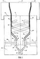
- Fig. 1 shows an annular extrusion die with an inner die body member 10 and an outer annular die body member 12 surrounding the inner die body member 10.
- the outer surface of the inner body member 10 has two helical grooves 14, 16 which commence at diametrically opposite positions in a lower portion of the inner body member 10 and extend upwardly in a helical manner in the same direction around the inner die body member 10 for just over 360°.
- the inner and outer die body members 10, 12 form a longitudinally extending annular passage 18 with which the grooves 12, 14 are in communication and which leads to an annular extrusion orifice 20.
- the extrusion orifice 20 is actually formed by inner and outer lip members 19, 21 mounted on top of the inner and outer die body members 10, 12 in known manner.
- the inner and outer body members 10, 12 are mounted on a base member 22 which has a main feed passage 24 for degradable plastic material extending upwardly from the bottom thereof.
- the main passage 24 divides into two feed passages 26, 28.
- Two encapsulating units 30, 32 are located between the inner body member 10 and the base member 22 and have inlets 34, 36 communicating with the feed passages 26, 28 respectively.
- Each encapsulating unit 30, 32 encapsulates degradable plastic material passing therethrough from the feed passages 26, 28 respectively in a circumferentially continuous manner with non-degradable plastic material supplied to the encapsulating units 30, 32 through passages 38, 40 respectively, the passages 38, 40 each being partly in the outer body member 12 and partly in the inner body member 10.
- Each encapsulating unit 30, 32 has an outlet 42, 44 respectively which feed an encapsulated stream of plastic material, i.e. a stream of degradable plastic material encapsulated in a circumferentially continuous manner with a non-degradable plastic material, to the lower ends of the helical grooves 14, 16 respectively through feed passages 46, 48 respectively in the inner body members 10.
- plastic material i.e. a stream of degradable plastic material encapsulated in a circumferentially continuous manner with a non-degradable plastic material
- a melt stream of degradable plastic material which may be vapour barrier material, such as PVDC or EVOH, is passed into the main feed passage 24 and then divided into two streams which pass through passages 26, 28 to the encapsulating units 30, 32 where the divided streams are completely encapsulated around their circumferences with non-degradable plastic material, such as EVA.
- the encapsulated streams then pass through passages 46, 28 into the helical grooves 14, 16. Until the 180° position of the helical grooves 14, 16, the encapsulated material passes into the lower narrower portion 18'' of the annular passage 18 to form a three layer tubular film of plastic material, i.e.
- a tubular film with an inner layer of degradable plastic material and inner and outer layers of non-degradable plastic material.
- encapsulated plastic material passes from the helical grooves 14, 16 into the wider portion 18' of the annular passage 18 to form further layers on the inside of the previously formed tubular film.
- the resultant five layer tubular film is then extruded from the annular die orifice 20.
- the helical grooves 14, 16 extend around the inner die body member 10 in the same direction for slightly more than 360°.
- the resultant tubular film has a central relatively thick layer of non-degradable plastic material, a layer of degradable plastic material on the inner and outer sides thereof, and innermost and outermost layers of non-degradable plastic material.
- the degradable plastic material is vapour barrier material
- the tubular film is provided with two vapour barrier layers.
- the presence of two vapour barrier layers minimizes the possibility of irregularities or pinholes in the barrier layers causing a problem, because irregularities or pinholes in one barrier layer are unlikely to be radially aligned with irregularities or pinholes in the other barrier layer.
- each vapour barrier layer can be relatively thin, for example below 10 microns, to reduce the possibility of the barrier layer cracking, as happens with some plastic materials (for example highly crystalline plastic material) when the barrier layer is thicker.
- some plastic materials for example highly crystalline plastic material
- the alternating layers of rigid and elastic plastic material provide a tubular film of high impact strength.
- the helical grooves 14, 16 may extend around the inner die body member 10 in the same direction for just over 180° so as to form as three layer tubular film. Alternatively, the helical grooves 14, 16 may extend around the inner body member 10 for just over 540° to produce a seven layer tubular film. Also, the degradable plastic material entering the passage 24 may be circumferentially encapsulated with non-degradable plastic material as primary encapsulation, with the encapsulating units 30, 32 thus providing secondary encapsulation.
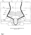
- Fig. 2 shows another embodiment of the invention.
- parts of the die shown in Fig. 2 will be given reference numerals which are 100 higher than the reference numerals given to similar parts of the die shown in Fig. 1.
- Fig. 2 shows an annular extrusion die with an inner die body member 110 and an outer annular die body member 112 surrounding the inner die body member 110.
- the outer surface of the inner body member 110 has two helical grooves 114, 116 which commence at diametrically opposite positions in a lower portion of the inner body member 10 and extend upwardly in a helical manner in the same direction around the inner die body member 110 for just over 360°.
- the inner and outer die body members 110, 112 form a longitudinally extending annular passage 118 with which the grooves 114, 116, are in communication and which leads to an annular extrusion orifice 120.
- the extrusion orifice 120 is actually formed by inner and outer lip members 119, 121 mounted on top of the inner and outer die body members 110, 112 in known manner.
- the inner and outer body members 110, 112 are mounted on a base member 122 which has a main feed passage 124 for degradable plastic material extending upwardly from the bottom thereof. Within the body member 122, the main passage 124 divides into two feed passages 126, 128. Two encapsulating units 130, 132 are located between the inner body member 110 and the base member 122 and have inlets 134, 136 communicating with the feed passages 126, 128 respectively.
- Each encapsulating unit 130, 132 encapsulates degradable plastic material passing therethrough from the feed passages 126, 128 respectively in a circumferentially continuous manner with non-degradable plastic material supplied to the encapsulating units 130, 132 through passages 138, 140 respectively, the passages 138, 140 each being partly in the outer body member 112 and partly in the inner body member 110.
- Each encapsulating unit 130, 132 has an outlet 142, 144 respectively which feed an encapsulated stream of plastic material, i.e. a stream of degradable plastic material encapsulated in a circumferentially continuous manner with a non-degradable plastic material, to the lower ends of the helical grooves 114, 116 respectively through feed passages 146, 148 respectively in the inner body members 110.
- plastic material i.e. a stream of degradable plastic material encapsulated in a circumferentially continuous manner with a non-degradable plastic material
- the inner surface of the outer body member 112 and the outer surface of the inner body member 110 are shaped in such a manner that the lower portion 118a of the annular passage 118 extends in an upwardly and outwardly inclined direction relative to the longitudinal axis A of the die, and the upper portion 118b of the annular passage 118 extends parallel to the longitudinal axis a of the die. It will be noted that the upper portion 118b of the annular passage 118 is relatively short compared to the lower portion 118a of the annular passage 118.
- a melt stream of degradable plastic material which may be vapour barrier material, such as PVDC or EVOH, is passed into the main feed passage 124 and then divided into two streams which pass through passages 126, 128 to the encapsulating units 130, 132 where the divided streams are completely encapsulated around their circumferences with non-degradable plastic material, such as EVA.
- the encapsulated streams then pass through passages 146, 148 into the helical grooves 114, 116. Until the 180° position of the helical grooves 114, 116, the encapsulated material passes into the lower narrower portion 118'' of the annular passage 118 to form a three layer tubular film of plastic material, i.e.
- a tubular film with an inner layer of degradable plastic material and outer layers of non-degradable plastic material. Beyond the 180° position 150, encapsulated plastic material passes from the helical grooves 114, 116 into the wider portion 118' of the annular passage 118 to form further layers on the inside of the previously formed tubular film. The resultant five layer tubular film is then extruded from the annular die orifice 120.
- the helical grooves 14, 16 extend around the inner die body member 10 in the same direction for slightly more than 360°.
- the resultant tubular film has a central relatively thick layer of non-degradable plastic material, a layer of degradable plastic material on the inner and outer sides thereof, and innermost and outermost layers of non-degradable plastic material.
- the degradable plastic material is vapour barrier material
- the tubular film is provided with two vapour barrier layers.
- the presence of two vapour barrier layers minimizes the possibility of irregularities or pinholes in the barrier layers causing a problem, because irregularities or pinholes in one barrier layer are unlikely to be radially aligned with irregularities or pinholes in the other barrier layer.
- each vapour barrier layer can be relatively thin, for example less than 10 microns, to reduce the possibility of the barrier layer cracking, as happens with some plastic materials (for example highly crystalline plastic material) when the barrier layer is thicker.
- some plastic materials for example highly crystalline plastic material
- the alternating layers of rigid and elastic plastic material provide a tubular film of high impact strength.
- the helical grooves 114, 116 may extend around the inner die body member 110 in the same direction for just over 180° so as to form a three layer tubular film. Alternatively, the helical grooves 114, 116 may extend around the inner die body member 110 for just over 540° to produce a seven layer tubular film. Also, the degradable plastic material entering the passage 124 may be circumferentially encapsulated with non-degradable plastic material as primary encapsulation, with the encapsulating units 130, 132 thus providing secondary encapsulation.
- Fig. 3 shows another embodiment of the invention.
- parts of the die shown in Fig. 3 will be given reference numerals which are one hundred higher than the reference numerals given to similar parts of the die shown in Fig. 2.
- the die shown in Fig. 3 is similar shown in Fig. 2 except that the inner surface of the outer body member 212 and the outer surface of the inner body member 210 are shaped in such a manner that the lower portion 218a of the annular passage 218 extends in an upwardly and inwardly inclined direction relative to the longitudinal axis a of the die and the upper portion 218b of the annular passage 218 extends parallel to the longitudinal axis A.
- the upper portion 218b of the annular passage 218 is relatively short compared to the lower portion 218a of the annular passage 218.
- Figs. 4 and 5 show another embodiment of the invention which is somewhat similar to the embodiment shown in Fig. 3. Therefore, the same reference numerals will be used in Figs. 4 and 5 to identify pans which are the same or similar to parts shown in Fig. 3. It will be noted that, whereas in the embodiment of Fig. 3 the helical groove 214 is in the inner body member 210, the equivalent helical groove 214a in the embodiment of Figs. 4 and 5 is in the outer body member 212.
- Figs. 6 and 7 show another embodiment of the invention which is somewhat similar to the embodiment shown in Figs. 4 and 5. Therefore, the same reference numerals will be used in Figs. 6 and 7 to identify parts which are the same or similar to parts shown in Figs. 4 and 5. It will be noted that, whereas in the embodiment of Figs. 4 and 5 there are two encapsulating units 230, 232, there is only one encapsulating unit 231 in the embodiment of Figs. 6 and 7 which supplies both feed passages 246, 248.
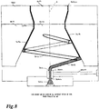
- Fig. 8 shows another embodiment of the invention.
- pans of the die shown in Fig. 8 will be given reference numerals which are one hundred higher than the reference numerals given to similar parts of the die shown in Fig. 3.
- the die shown in Fig. 8 is similar to the die shown in Fig. 3 except that the inner body member 310 has a single helical groove 316 which extends around the inner body member 310 for just over 360°.
- the degradable plastic material fed into the die through main feed passage 324 is encapsulated in a circumferentially continuous manner by encapsulating unit 332 which is supplied with non-degradable plastic material through passage 340.
- the die shown in Fig. 8 thus produces a three layer tubular film.
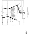
- Fig. 9 shows another embodiment of the invention.
- pans of the die shown in Fig. 9 will be given reference numerals which are one hundred higher than the reference numerals given to similar parts of the die shown in Fig. 8.
- the die shown in Fig. 9 is similar to the die shown in Fig. 8 except that the feed passage 448 feeds encapsulated material to a groove 416 which extends for 360° around the inner body member 410 and feeds encapsulated plastic material to multi-start helical passages 417 in the inner body member 410.
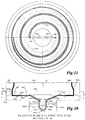
- Figs. 10 and 11 show another embodiment of the invention.
- the die has an inner body member 510 and a first outer body member 512 upon which the inner body member 510 is seated.
- the inner and outer body members 510, 512 have annular lower and upper surfaces respectively extending perpendicularly to the longitudinal axis A of the die and provided with helical grooves 516, 514 respectively which commence at diametrically opposite positions and extend around the longitudinal axis of the die for 720°.
- the inner and outer body members 510, 512 form an annular passage 518a with which the grooves 514, 516 are in communication and which extends in a direction perpendicular to the longitudinal axis a of the die.
- the die also has a second outer body member 511 which surrounds the inner body member 510 and is mounted on the first outer body member 512.
- the second outer body member 511 and the inner body member 510 form an annular passage 518b therebetween which extends parallel to the longitudinal axis A of the die and which, with annular passage 518a, form an annular passage 518 extending to an annular extrusion orifice 520.
- the extrusion orifice 520 is formed by inner and outer lip members 519, 521 mounted on top of the inner body member 510 and the second outer body member 511 respectively.
- the outer body member 512 has a main feed passage 524 for degradable plastic material extending upwardly from the bottom thereof. Within the outer body member 512, the main feed passage 524 divides into two feed passages 526, 528 respectively.
- Two encapsulating units 530, 532 are located in the outer and inner body members 512, 510 and have inlets 534, 536 communicating with the feed passages 526, 528 respectively.
- Each encapsulating unit 530, 532 encapsulated degradable plastic material passing therethrough from the passages 526, 528 respectively in a circumferentially continuous manner with non-degradable plastic material being supplied to the encapsulating units 530, 532 through passages 538, 540 respectively in the outer body member 512.
- Each encapsulating unit 530, 532 has an outlet 542, 544 respectively which feeds an encapsulated stream of plastic material, i.e. a stream of degradable plastic material encapsulated in a circumferentially continuous manner with a non-degradable plastic material, to the radially inner ends of the helical grooves 514, 516 respectively through feed passages 546, 548 respectively.
- the width of the annular passage 518' beyond the portion 550 is somewhat wider than the width of the annular passage 518'' before the position 550.
- a melt stream of degradable plastic material is passed into the main feed passage 524 and then divided into two streams which pass through passages 526, 528 to the encapsulating units 530, 532 where the divided streams are concurrently encapsulated around their circumferences with non-degradable plastic material.
- the encapsulated streams then pass through passages 546, 548 into the helical groove 514, 516.
- the encapsulated material passes into the initial narrow portion 518'' of the annular passage 518 to form a three layer film of tubular material, i.e. a tubular film with an inner layer of degradable plastic material and outer layers of non-degradable plastic material.
- encapsulated plastic material passes from the helical grooves 514, 516 into the wider portion 518' of the annular passage 518 to form further layers on the inside of the previously formed tubular film.
- the resultant five layer tubular film is then extruded from the annular die orifice 520.
- the helical grooves 514, 516 extend around the inner die body members 510, 512 in the same direction for 720°.
- the resultant tubular film has a central relatively thick layer of non-degradable plastic material, a layer of degradable plastic material on the inner and outer sides thereof, and innermost and outermost layers of non-degradable plastic material.
- the degradable plastic material is vapour barrier material
- the tubular film is provided with two vapour barrier layers.
- the presence of two vapour barrier layers minimizes the possibility of irregularities or pin holes in the barrier layers causing a problem because irregularities or pin holes in one barrier layer are unlikely to be radially aligned with irregularities or pin holes in the other barrier layer.
- each vapour barrier layer can be relatively thin, for example less than ten microns, to reduce the possibility of the barrier layer cracking, as happens with some plastic materials (for example highly crystalline plastic material) when the barrier layer is thicker.
- some plastic materials for example highly crystalline plastic material
- the alternating layers of rigid and elastic plastic material provide a tubular film of high impact strength.
- the helical grooves 514, 516 may extend around the inner die body member 510 in the same direction for just over 180° so as to form a three layer tubular film.
- the helical grooves 514, 516 may extend around the inner die body member 110 for just over 540° to produce a seven layer tubular film.
- the degradable plastic film entering the passage 524 may be circumferentially encapsulated with non-degradable plastic material as primary encapsulation, with the encapsulating units 530, 532 thus providing secondary encapsulation.
- Figs. 12 and 13 show another embodiment of the invention.
- parts of the die shown in Figs. 12 and 13 will be given reference numerals which are one hundred higher than the reference numerals given to similar parts of the dies shown in Figs. 10 and 11.
- the die shown in Figs. 12 and 13 differs from the dies shown in Figs. 10 and 11 in that the inner body member 610 has a series of helical grooves 614 which each extend 90°.
- the degradable plastic material is fed into the die through main feed passage 624 and is encapsulated in a circumferentially continuous manner by encapsulating unit 630 which is supplied with non-degradable plastic material through passage 638.
- the encapsulated material is then fed through feed passage 646 to annular groove 613 in the inner body member 610, and therefrom across a gap 615 to the helical groove 614.
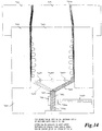
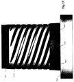
- Figs. 14 and 15 show another embodiment of the invention.
- pans of the die shown in Figs. 14 and 15 will be given reference numerals which are seven hundred higher than the reference numerals given to similar parts of the die shown in Fig. 1.
- the encapsulated plastic material 748 leaving the encapsulating unit 732 is divided into eight streams which respectively pass through eight equi-angularly spaced radially extending cross-holes 760 in the inner body member 710.
- Each cross-hole 760 supplies partially encapsulated material to a respective one of eight helical grooves 762 which extend around the inner body member 710 for 350° in an upwardly spiralling direction.
Abstract
Description
- This invention relates to the extrusion of plastic materials in multilayer tubular film. Although the invention is especially useful when one of the plastic materials is readily degradable, the invention is not limited to the use of a degradable plastic material. The invention may be used to produce multilayer tubular film in which the layers are of any suitable compatible plastic materials to enable such film to be produced in a more economical manner than before.
- It is well known that it is difficult to extrude some plastic materials, such as PVDC, because of their susceptibility to degradation during extrusion as a result of contact with the walls of the extrusion die. Attempts have been made to overcome this problem by encapsulating the degradable plastic material with non-degradable plastic material prior to extrusion. Such encapsulation was originally carried out when extruding plastic material in sheet form, but subsequent attempts have also been made to encapsulate plastic material during extrusion in tubular form from annular extrusion dies.
- Initial attempts to carry out encapsulation with annular extrusion dies have utilized the same general principle which was used with extrusion dies for sheet material, namely in which a melt stream of degradable plastic material encapsulated with non-degradable plastic material was divided into two streams and fed around the annular extrusion die in opposite directions and then re-joined on an opposite side of the die. Annular extrusion dies of these kind have been known as crosshead or side feed dies, a typical example being shown in U.S. Patent No. 5,143,677 (Blemberg et al). However, problems arise where the divided melt streams are rejoined. Attempts have been made to overcome this problem but have not been particularly successful because this method always produces problems in the area where the divided melt streams have been rejoined.
- It is therefore an object of the present invention to provide a method of extruding degradable plastic material in tubular form which substantially overcomes the problem mentioned above. However, as mentioned above, the invention is not limited to the use of degradable plastic material and can be used to produce multilayer film with a single die.
- According to the present invention, a method of extruding plastic materials in multilayer tubular film includes providing an annular extrusion die having an annular extrusion orifice and an annular passage for conveying plastic material to the extrusion orifice, the die also having at least one arcuate passage extending at least partly around the annular passage such that the arcuate passage completely surrounds, or where there is more than one arcuate passage in combination completely surround, the annular passage inwardly or outwardly thereof and is or are in communication therewith. A melt stream of plastic material is encapsulated with a different plastic material in a circumferentially continuous manner to produce a separate encapsulated melt stream. At least a portion of the encapsulated melt stream is fed to an arcuate passage to cause at least partially encapsulated plastic material to pass into the annular passage with subsequent extrusion in multilayer tubular form from the annular die orifice.
- The annular extrusion die may have an inner body member surrounded by an annular outer body member forming the longitudinally extending annular passage therebetween, with the inner body member having two arcuate passages formed by two helical grooves in the inner body member. The two helical grooves may commence at diametrically opposite positions in the inner body member and extend around the inner body member in the same direction.
- Each helical groove may extend around the inner body member for just over 180° so as to form a three layer tubular film. Alternatively, each helical groove may extend around the inner body member for just over 360° so as to form a five layer tubular film, and the longitudinally extending annular passage may be wider beyond the 180° position of the helical grooves than before the 180° position. In another alternative, each helical groove may extend around the inner body member for just over 540° so as to form a seven layer tubular film.
- At least one of the melt streams may be degradable plastic material, the associated encapsulating plastic material being a non-degradable plastic material. Thus, after encapsulation, none of the degradable plastic material contacts a die surface.
- The degradable plastic material may be a vapour barrier material. The vapour barrier material may be relatively rigid and the non-degradable plastic material encapsulating the vapour barrier material may be relatively elastic.
- The present invention also provides an annular extrusion die for extruding plastic materials in multilayer tubular film, the extrusion die having an inner body member and an outer body member surrounding the inner body member and forming an annular passage therebetween which communicates with an annular extrusion orifice. The inner body member has at least one helical groove for passing plastic material into the annular passage for subsequent extrusion in tubular form from the annular extrusion orifice. The die also has a supply passage for supplying a first plastic material to the helical groove or grooves, and an encapsulating unit for encapsulating the first plastic material with a second plastic material in a circumferentially continuous manner before the first plastic material enters the helical groove or grooves whereby the first plastic material entering a helical groove is at least partially encapsulated by the second plastic material.
- The inner body member may have two helical grooves extending around the inner body member in the same direction, with the die also having two encapsulating units, one of the encapsulating units operating to encapsulate a stream of plastic material with a different plastic material before it enters one of the helical grooves, and the other encapsulating unit operating to encapsulate a further stream of plastic material with a different plastic material before it enters the other helical groove.
- Embodiments of the invention will now be described, by way of example, with reference to the accompanying drawing, of which:
- Fig. 1 is a cross-sectional view of an annular extrusion die in accordance with one embodiment,
- Fig. 2 is a similar view of another embodiment,
- Fig. 3 is a similar view of another embodiment,
- Fig. 4 is a similar view of another embodiment,
- Fig. 5 is a diagrammatic sectional view along the line 5-5 of Fig. 4,
- Fig. 6 is a similar view of another embodiment,
- Fig. 7 is a diagrammatic sectional view along the line 7-7 of Fig. 6,
- Fig. 8 is a cross-sectional view of another embodiment,
- Fig. 9 is a cross-sectional of another embodiment,
- Fig. 10 is a cross-section view of another embodiment,
- Fig. 11 is a diagrammatic sectional view along the line 11-11 of Fig. 10,
- Fig. 12 is a cross-sectional view of another embodiment,
- Fig. 13 is a diagrammatic sectional view along the line 13-13 of Fig. 12,
- Fig. 14 is a cross-sectional view of another embodiment, and
- Fig. 15 is a side view of the inner body member and base member of the embodiment shown in Fig. 14.
-
- Referring to the drawings, Fig. 1 shows an annular extrusion die with an inner
die body member 10 and an outer annulardie body member 12 surrounding the innerdie body member 10. The outer surface of theinner body member 10 has twohelical grooves inner body member 10 and extend upwardly in a helical manner in the same direction around the innerdie body member 10 for just over 360°. The inner and outerdie body members annular passage 18 with which thegrooves annular extrusion orifice 20. Theextrusion orifice 20 is actually formed by inner andouter lip members die body members - The inner and
outer body members base member 22 which has amain feed passage 24 for degradable plastic material extending upwardly from the bottom thereof. Within thebody member 22, themain passage 24 divides into twofeed passages encapsulating units inner body member 10 and thebase member 22 and haveinlets feed passages unit feed passages units passages passages outer body member 12 and partly in theinner body member 10. - Each
encapsulating unit outlet helical grooves feed passages inner body members 10. - It will be noted that, at the
position 50 where eachhelical groove inner body portion 10 is reduced so that the width of the annular passage 18' above theposition 50 is somewhat greater than the width of the annular passage 18'' below theposition 50. - In use, a melt stream of degradable plastic material, which may be vapour barrier material, such as PVDC or EVOH, is passed into the
main feed passage 24 and then divided into two streams which pass throughpassages encapsulating units passages helical grooves helical grooves annular passage 18 to form a three layer tubular film of plastic material, i.e. a tubular film with an inner layer of degradable plastic material and inner and outer layers of non-degradable plastic material. Beyond the 180°position 50, encapsulated plastic material passes from thehelical grooves annular passage 18 to form further layers on the inside of the previously formed tubular film. The resultant five layer tubular film is then extruded from theannular die orifice 20. - As shown in the drawing, the
helical grooves die body member 10 in the same direction for slightly more than 360°. The resultant tubular film has a central relatively thick layer of non-degradable plastic material, a layer of degradable plastic material on the inner and outer sides thereof, and innermost and outermost layers of non-degradable plastic material. Thus, when the degradable plastic material is vapour barrier material, the tubular film is provided with two vapour barrier layers. The presence of two vapour barrier layers minimizes the possibility of irregularities or pinholes in the barrier layers causing a problem, because irregularities or pinholes in one barrier layer are unlikely to be radially aligned with irregularities or pinholes in the other barrier layer. Further, in this case, each vapour barrier layer can be relatively thin, for example below 10 microns, to reduce the possibility of the barrier layer cracking, as happens with some plastic materials (for example highly crystalline plastic material) when the barrier layer is thicker. Also, when the degradable plastic material is relatively rigid and the non-degradable plastic material is relatively elastic, the alternating layers of rigid and elastic plastic material provide a tubular film of high impact strength. - It will be understood that the
helical grooves die body member 10 in the same direction for just over 180° so as to form as three layer tubular film. Alternatively, thehelical grooves inner body member 10 for just over 540° to produce a seven layer tubular film. Also, the degradable plastic material entering thepassage 24 may be circumferentially encapsulated with non-degradable plastic material as primary encapsulation, with the encapsulatingunits - Fig. 2 shows another embodiment of the invention. For ease of understanding, parts of the die shown in Fig. 2 will be given reference numerals which are 100 higher than the reference numerals given to similar parts of the die shown in Fig. 1.
- Fig. 2 shows an annular extrusion die with an inner
die body member 110 and an outer annulardie body member 112 surrounding the innerdie body member 110. The outer surface of theinner body member 110 has twohelical grooves inner body member 10 and extend upwardly in a helical manner in the same direction around the innerdie body member 110 for just over 360°. The inner and outerdie body members annular passage 118 with which thegrooves annular extrusion orifice 120. Theextrusion orifice 120 is actually formed by inner andouter lip members die body members - The inner and
outer body members base member 122 which has amain feed passage 124 for degradable plastic material extending upwardly from the bottom thereof. Within thebody member 122, themain passage 124 divides into twofeed passages 126, 128. Two encapsulatingunits inner body member 110 and thebase member 122 and haveinlets feed passages 126, 128 respectively. Each encapsulatingunit feed passages 126, 128 respectively in a circumferentially continuous manner with non-degradable plastic material supplied to the encapsulatingunits passages passages outer body member 112 and partly in theinner body member 110. - Each encapsulating
unit outlet helical grooves feed passages inner body members 110. - It will be noted that, at the
position 150 where eachhelical groove inner body portion 110 is reduced so that the width of the annular passage 118' above theposition 150 is somewhat greater than the width of the annular passage 118'' below theposition 150. - The inner surface of the
outer body member 112 and the outer surface of theinner body member 110 are shaped in such a manner that the lower portion 118a of theannular passage 118 extends in an upwardly and outwardly inclined direction relative to the longitudinal axis A of the die, and the upper portion 118b of theannular passage 118 extends parallel to the longitudinal axis a of the die. It will be noted that the upper portion 118b of theannular passage 118 is relatively short compared to the lower portion 118a of theannular passage 118. - In use, a melt stream of degradable plastic material, which may be vapour barrier material, such as PVDC or EVOH, is passed into the
main feed passage 124 and then divided into two streams which pass throughpassages 126, 128 to the encapsulatingunits passages helical grooves helical grooves annular passage 118 to form a three layer tubular film of plastic material, i.e. a tubular film with an inner layer of degradable plastic material and outer layers of non-degradable plastic material. Beyond the 180°position 150, encapsulated plastic material passes from thehelical grooves annular passage 118 to form further layers on the inside of the previously formed tubular film. The resultant five layer tubular film is then extruded from theannular die orifice 120. - As shown in Fig. 2, the
helical grooves die body member 10 in the same direction for slightly more than 360°. The resultant tubular film has a central relatively thick layer of non-degradable plastic material, a layer of degradable plastic material on the inner and outer sides thereof, and innermost and outermost layers of non-degradable plastic material. Thus, when the degradable plastic material is vapour barrier material, the tubular film is provided with two vapour barrier layers. The presence of two vapour barrier layers minimizes the possibility of irregularities or pinholes in the barrier layers causing a problem, because irregularities or pinholes in one barrier layer are unlikely to be radially aligned with irregularities or pinholes in the other barrier layer. Further, in this case, each vapour barrier layer can be relatively thin, for example less than 10 microns, to reduce the possibility of the barrier layer cracking, as happens with some plastic materials (for example highly crystalline plastic material) when the barrier layer is thicker. Also, when the degradable plastic material is relatively rigid and the non-degradable plastic material is relatively elastic, the alternating layers of rigid and elastic plastic material provide a tubular film of high impact strength. - It will be understood that the
helical grooves die body member 110 in the same direction for just over 180° so as to form a three layer tubular film. Alternatively, thehelical grooves die body member 110 for just over 540° to produce a seven layer tubular film. Also, the degradable plastic material entering thepassage 124 may be circumferentially encapsulated with non-degradable plastic material as primary encapsulation, with the encapsulatingunits - Fig. 3 shows another embodiment of the invention. For ease of understanding, parts of the die shown in Fig. 3 will be given reference numerals which are one hundred higher than the reference numerals given to similar parts of the die shown in Fig. 2.
- The die shown in Fig. 3 is similar shown in Fig. 2 except that the inner surface of the
outer body member 212 and the outer surface of theinner body member 210 are shaped in such a manner that the lower portion 218a of theannular passage 218 extends in an upwardly and inwardly inclined direction relative to the longitudinal axis a of the die and the upper portion 218b of theannular passage 218 extends parallel to the longitudinal axis A. The upper portion 218b of theannular passage 218 is relatively short compared to the lower portion 218a of theannular passage 218. - Figs. 4 and 5 show another embodiment of the invention which is somewhat similar to the embodiment shown in Fig. 3. Therefore, the same reference numerals will be used in Figs. 4 and 5 to identify pans which are the same or similar to parts shown in Fig. 3. It will be noted that, whereas in the embodiment of Fig. 3 the
helical groove 214 is in theinner body member 210, the equivalent helical groove 214a in the embodiment of Figs. 4 and 5 is in theouter body member 212. - Figs. 6 and 7 show another embodiment of the invention which is somewhat similar to the embodiment shown in Figs. 4 and 5. Therefore, the same reference numerals will be used in Figs. 6 and 7 to identify parts which are the same or similar to parts shown in Figs. 4 and 5. It will be noted that, whereas in the embodiment of Figs. 4 and 5 there are two encapsulating
units encapsulating unit 231 in the embodiment of Figs. 6 and 7 which supplies both feedpassages - Fig. 8 shows another embodiment of the invention. For ease of understanding, pans of the die shown in Fig. 8 will be given reference numerals which are one hundred higher than the reference numerals given to similar parts of the die shown in Fig. 3.
- The die shown in Fig. 8 is similar to the die shown in Fig. 3 except that the
inner body member 310 has a singlehelical groove 316 which extends around theinner body member 310 for just over 360°. The degradable plastic material fed into the die throughmain feed passage 324 is encapsulated in a circumferentially continuous manner by encapsulatingunit 332 which is supplied with non-degradable plastic material through passage 340. The die shown in Fig. 8 thus produces a three layer tubular film. - Fig. 9 shows another embodiment of the invention. For ease of understanding, pans of the die shown in Fig. 9 will be given reference numerals which are one hundred higher than the reference numerals given to similar parts of the die shown in Fig. 8.
- The die shown in Fig. 9 is similar to the die shown in Fig. 8 except that the
feed passage 448 feeds encapsulated material to agroove 416 which extends for 360° around theinner body member 410 and feeds encapsulated plastic material to multi-starthelical passages 417 in theinner body member 410. - Figs. 10 and 11 show another embodiment of the invention. In this embodiment, the die has an
inner body member 510 and a firstouter body member 512 upon which theinner body member 510 is seated. The inner andouter body members helical grooves outer body members grooves inner body member 510 and is mounted on the firstouter body member 512. The second outer body member 511 and theinner body member 510 form anannular passage 518b therebetween which extends parallel to the longitudinal axis A of the die and which, with annular passage 518a, form anannular passage 518 extending to an annular extrusion orifice 520. The extrusion orifice 520 is formed by inner andouter lip members inner body member 510 and the second outer body member 511 respectively. - The
outer body member 512 has amain feed passage 524 for degradable plastic material extending upwardly from the bottom thereof. Within theouter body member 512, themain feed passage 524 divides into twofeed passages units 530, 532 are located in the outer andinner body members inlets feed passages unit 530, 532 encapsulated degradable plastic material passing therethrough from thepassages units 530, 532 throughpassages outer body member 512. - Each encapsulating
unit 530, 532 has anoutlet helical grooves feed passages position 550 at whichhelical grooves portion 550 is somewhat wider than the width of the annular passage 518'' before theposition 550. - In use, a melt stream of degradable plastic material is passed into the
main feed passage 524 and then divided into two streams which pass throughpassages units 530, 532 where the divided streams are concurrently encapsulated around their circumferences with non-degradable plastic material. The encapsulated streams then pass throughpassages helical groove annular passage 518 to form a three layer film of tubular material, i.e. a tubular film with an inner layer of degradable plastic material and outer layers of non-degradable plastic material. Beyond the 180° position, encapsulated plastic material passes from thehelical grooves annular passage 518 to form further layers on the inside of the previously formed tubular film. The resultant five layer tubular film is then extruded from the annular die orifice 520. - As shown in Fig. 11, the
helical grooves die body members - It will be understood that the
helical grooves die body member 510 in the same direction for just over 180° so as to form a three layer tubular film. Alternatively, thehelical grooves die body member 110 for just over 540° to produce a seven layer tubular film. Also, the degradable plastic film entering thepassage 524 may be circumferentially encapsulated with non-degradable plastic material as primary encapsulation, with the encapsulatingunits 530, 532 thus providing secondary encapsulation. - Figs. 12 and 13 show another embodiment of the invention. For ease of understanding, parts of the die shown in Figs. 12 and 13 will be given reference numerals which are one hundred higher than the reference numerals given to similar parts of the dies shown in Figs. 10 and 11.
- The die shown in Figs. 12 and 13 differs from the dies shown in Figs. 10 and 11 in that the inner body member 610 has a series of
helical grooves 614 which each extend 90°. The degradable plastic material is fed into the die throughmain feed passage 624 and is encapsulated in a circumferentially continuous manner by encapsulatingunit 630 which is supplied with non-degradable plastic material throughpassage 638. The encapsulated material is then fed throughfeed passage 646 toannular groove 613 in the inner body member 610, and therefrom across agap 615 to thehelical groove 614. - Figs. 14 and 15 show another embodiment of the invention. For ease of understanding, pans of the die shown in Figs. 14 and 15 will be given reference numerals which are seven hundred higher than the reference numerals given to similar parts of the die shown in Fig. 1.
- The encapsulated
plastic material 748 leaving the encapsulatingunit 732 is divided into eight streams which respectively pass through eight equi-angularly spaced radially extendingcross-holes 760 in theinner body member 710. Each cross-hole 760 supplies partially encapsulated material to a respective one of eight helical grooves 762 which extend around theinner body member 710 for 350° in an upwardly spiralling direction. - It should be noted that, although the described embodiments have primarily been concerned with the extrusion of degradable plastic material encapsulated with non-degradable plastic material, the invention is not limited to the use of degradable plastic material. The dies described may be used to produce multilayer tubular plastic films with layers of any suitable compatible plastic material.
- Other embodiments of the invention will now be readily apparent to a person skilled in the art from the foregoing description of preferred embodiments. The scope of the invention being defined in the appended claims.
Claims (16)
- A method of extruding plastic materials in multilayer tubular form including:providing an annular extrusion die having an annular extrusion orifice and annular passage for conveying plastic material to the extrusion orifice,the die also having at least one arcuate passage extending at least partly around the annular passage such that the arcuate passage completely surrounds, or where there is more than one arcuate passage in combination completely surround, the annular passage inwardly or outwardly thereof and is or are in communication therewith,encapsulating a melt stream of plastic material with a different plastic material in a circumferentially continuous manner to produce an encapsulated melt stream, andfeeding at least a portion of the encapsulated melt stream to an arcuate passage to cause at least partially encapsulated plastic material to pass into the annular passage with subsequent extrusion in multilayer tubular form from the annular die orifice.
- A method according to claim 1 wherein the annular passage for conveying plastic material is substantially parallel to the longitudinal axis of the die.
- A method according to claim 1 wherein the annular extrusion die has an inner body member surrounded by an annular outer body member forming the annular passage therebetween, and the inner body member has two arcuate passages formed by two helical grooves in the inner body member.
- A method according to claim 3 wherein the two helical grooves commence at diametrically opposite positions in the inner body member and extend around the inner body member in the same direction.
- A method according to claim 4 wherein each helical groove extends around the inner body member for just over 180° so as to form a three layer tubular film.
- A method according to claim 4 wherein each helical groove extends around the inner body member for just over 360° so as to form a five layer tubular film.
- A method according to claim 6 wherein the longitudinally extending annular passage is wider beyond the 180° position of the helical grooves than before said 180° position.
- A method according to claim 4 wherein each helical groove extends around the inner body member for just over 540° so as to form a seven layer tubular film.
- A method according to claim 1 wherein at least on the melt streams is of degradable plastic material, with the associated encapsulating plastic material being a non-degradable plastic material.
- A method according to claim 9 wherein the degradable plastic material is vapour barrier material.
- A method according to claim 10 wherein the vapour barrier material is relatively rigid and the non-degradable plastic material encapsulating the vapour barrier material is relatively elastic.
- An annular extrusion die for extruding plastic materials in multilayer tubular form, said extrusion die having an inner body member and an outer body member surrounding the inner body member and forming an annular passage therebetween which communicates with an annular extrusion orifice,the inner body member having at least one helical groove for passing plastic material into the annular passage for subsequent extrusion in tubular form from the annular extrusion orifice,the die also having a supply passage for supplying a first plastic material to the helical groove or grooves, andan encapsulating unit for encapsulating the first plastic material with a second plastic material in a circumferentially continuous manner before the first plastic material enters the helical groove or grooves whereby the first plastic material entering a helical groove is at least partially encapsulated by the second plastic material.
- An extrusion die according to claim 12 wherein the annular passage between the outer and inner body members extend substantially parallel to the longitudinal axis of the die.
- An extrusion die according to claim 12 wherein the inner body member has two helical grooves extending around the inner body member in the same direction, and the die also has two encapsulating units, one of the encapsulating units operating to encapsulate a stream of plastic material with a different plastic material before it enters one of the helical grooves, and the other encapsulating unit operating to encapsulate a further stream of plastic material with a different plastic material before it enters the other helical groove.
- An extrusion die according to claim 14 wherein the two helical grooves commence at diametrically opposite positions and extend around the inner body member for just over 360° so as to form a five layer tubular film.
- An extrusion die according to claim 15 wherein the longitudinally extending passage is wider beyond the 180° position of the helical grooves than prior to the 180° position.
Applications Claiming Priority (2)
| Application Number | Priority Date | Filing Date | Title |
|---|---|---|---|
| US09/082,477 US6116885A (en) | 1997-03-21 | 1998-05-21 | Extrusion of plastic materials in multilayer tubular film |
| US82477 | 1998-05-21 |
Publications (1)
| Publication Number | Publication Date |
|---|---|
| EP0965433A1 true EP0965433A1 (en) | 1999-12-22 |
Family
ID=22171469
Family Applications (1)
| Application Number | Title | Priority Date | Filing Date |
|---|---|---|---|
| EP98202614A Withdrawn EP0965433A1 (en) | 1998-05-21 | 1998-08-03 | Extrusion of plastic materials in multilayer tubular film |
Country Status (3)
| Country | Link |
|---|---|
| US (2) | US6116885A (en) |
| EP (1) | EP0965433A1 (en) |
| CA (1) | CA2243918A1 (en) |
Cited By (1)
| Publication number | Priority date | Publication date | Assignee | Title |
|---|---|---|---|---|
| EP3479993A1 (en) * | 2017-11-07 | 2019-05-08 | W. Müller GmbH | Ring distributor for an extruder head for manufacturing a hose-like moulded material made of thermoplastic material |
Families Citing this family (13)
| Publication number | Priority date | Publication date | Assignee | Title |
|---|---|---|---|---|
| US6116885A (en) * | 1997-03-21 | 2000-09-12 | Macro Engineering & Technology Inc. | Extrusion of plastic materials in multilayer tubular film |
| US6343919B1 (en) * | 2000-02-28 | 2002-02-05 | Ricardo Pablo Rodriguez | Modular plastics extrusion die |
| DE10107191A1 (en) * | 2001-02-16 | 2002-09-05 | Unicor Rohrsysteme Gmbh | Device for the production of plastic pipes |
| US20100072655A1 (en) | 2008-09-23 | 2010-03-25 | Cryovac, Inc. | Die, system, and method for coextruding a plurality of fluid layers |
| US8876512B2 (en) * | 2008-09-23 | 2014-11-04 | Cryovac, Inc. | Die for coextruding a plurality of fluid layers |
| US8012572B2 (en) | 2009-03-06 | 2011-09-06 | Cryovac, Inc. | Multilayer, heat-shrinkable film comprising a plurality of microlayers |
| US20110229701A1 (en) | 2010-03-18 | 2011-09-22 | Cryovac, Inc. | Multilayer Active Oxygen Barrier Film Comprising a Plurality of Microlayers |
| US20110229722A1 (en) * | 2010-03-18 | 2011-09-22 | Cryovac, Inc. | Multilayer Oxygen Barrier Film Comprising a Plurality of Adjoining Microlayers Comprising Ethylene/Vinyl Alcohol Copolymer |
| US20120160728A1 (en) | 2010-12-22 | 2012-06-28 | Cryovac, Inc. | Multi-Segment, Heat-Shrinkable Barrier Film Comprising a Plurality of Microlayers |
| USD749157S1 (en) * | 2014-01-05 | 2016-02-09 | Makerbot Industries, Llc | Three-dimensional printer extruder carriage |
| US20170036386A1 (en) * | 2014-04-03 | 2017-02-09 | Macro Technology Ltd. | Co-extrusion die with rectangular feed channel |
| US20180001609A1 (en) | 2014-12-24 | 2018-01-04 | Sealed Air Corporation (Us) | Multilayer, Heat-Shrinkable Film Comprising a Plurality of Microlayers |
| WO2017100934A1 (en) * | 2015-12-16 | 2017-06-22 | Tronoplast Technologies Inc. | Coextrusion mandrel for extrusion die |
Citations (6)
| Publication number | Priority date | Publication date | Assignee | Title |
|---|---|---|---|---|
| US3649143A (en) * | 1969-05-01 | 1972-03-14 | Pierson Ind Inc | Composite tubular film apparatus |
| US4687430A (en) * | 1986-03-21 | 1987-08-18 | Dennis Morris | Co-extrusion die |
| EP0435786A2 (en) * | 1989-12-28 | 1991-07-03 | American National Can Company | Extrusion methods and apparatus, and structures produced therewith |
| US5143677A (en) * | 1987-12-31 | 1992-09-01 | American National Can Company | Co-extrusions methods |
| EP0703066A1 (en) * | 1994-09-21 | 1996-03-27 | Kureha Kagaku Kogyo Kabushiki Kaisha | Obliquely laminated resin product |
| US5788902A (en) * | 1997-03-21 | 1998-08-04 | Planeta; Mirek | Extrusion of degradable plastic material in tubular form |
Family Cites Families (3)
| Publication number | Priority date | Publication date | Assignee | Title |
|---|---|---|---|---|
| US4784594A (en) * | 1983-03-11 | 1988-11-15 | Mobil Oil Corporation | Single lip rotary tubular extrusion die |
| JP3471924B2 (en) * | 1994-09-21 | 2003-12-02 | 呉羽化学工業株式会社 | Spiral die and method of manufacturing laminate using the same |
| US6116885A (en) * | 1997-03-21 | 2000-09-12 | Macro Engineering & Technology Inc. | Extrusion of plastic materials in multilayer tubular film |
-
1998
- 1998-05-21 US US09/082,477 patent/US6116885A/en not_active Expired - Lifetime
- 1998-07-24 CA CA002243918A patent/CA2243918A1/en not_active Abandoned
- 1998-08-03 EP EP98202614A patent/EP0965433A1/en not_active Withdrawn
-
2000
- 2000-05-30 US US09/586,559 patent/US6409953B1/en not_active Expired - Lifetime
Patent Citations (6)
| Publication number | Priority date | Publication date | Assignee | Title |
|---|---|---|---|---|
| US3649143A (en) * | 1969-05-01 | 1972-03-14 | Pierson Ind Inc | Composite tubular film apparatus |
| US4687430A (en) * | 1986-03-21 | 1987-08-18 | Dennis Morris | Co-extrusion die |
| US5143677A (en) * | 1987-12-31 | 1992-09-01 | American National Can Company | Co-extrusions methods |
| EP0435786A2 (en) * | 1989-12-28 | 1991-07-03 | American National Can Company | Extrusion methods and apparatus, and structures produced therewith |
| EP0703066A1 (en) * | 1994-09-21 | 1996-03-27 | Kureha Kagaku Kogyo Kabushiki Kaisha | Obliquely laminated resin product |
| US5788902A (en) * | 1997-03-21 | 1998-08-04 | Planeta; Mirek | Extrusion of degradable plastic material in tubular form |
Cited By (7)
| Publication number | Priority date | Publication date | Assignee | Title |
|---|---|---|---|---|
| EP3479993A1 (en) * | 2017-11-07 | 2019-05-08 | W. Müller GmbH | Ring distributor for an extruder head for manufacturing a hose-like moulded material made of thermoplastic material |
| WO2019091926A1 (en) * | 2017-11-07 | 2019-05-16 | W. Müller GmbH | Ring-type distributor for an extrusion die for producing a tubular blank from thermoplastic material |
| KR20200074210A (en) * | 2017-11-07 | 2020-06-24 | 베. 뮐러 게엠베하 | Annular manifold for extrusion heads for manufacturing tubular moldings from thermoplastic materials |
| CN111491774A (en) * | 2017-11-07 | 2020-08-04 | W·米勒有限公司 | Annular distributor for extrusion dies for producing tubular blanks from thermoplastic material |
| TWI714902B (en) * | 2017-11-07 | 2021-01-01 | 德商W 穆勒有限公司 | Annular manifold for an extrusion head for producing a tubular moulding from a thermoplastic material |
| CN111491774B (en) * | 2017-11-07 | 2022-06-03 | W·米勒有限公司 | Ring manifold for extrusion parison head for producing tubular molded parts from thermoplastic material |
| US11660798B2 (en) | 2017-11-07 | 2023-05-30 | W. Müller GmbH | Annular manifold for an extrusion head for producing a tubular moulding from a thermoplastic material |
Also Published As
| Publication number | Publication date |
|---|---|
| US6116885A (en) | 2000-09-12 |
| US6409953B1 (en) | 2002-06-25 |
| CA2243918A1 (en) | 1999-11-21 |
Similar Documents
| Publication | Publication Date | Title |
|---|---|---|
| EP0965433A1 (en) | Extrusion of plastic materials in multilayer tubular film | |
| EP1007321B1 (en) | Annular co-extrusion die | |
| CA2415277C (en) | Tubular multilayer films, method and apparatus for preparing the same | |
| US5882694A (en) | Extrusion system with balanced flow passage | |
| CA2169212C (en) | Method and installation for the production of a multilayer pipe of thermoplastic material, in particular polyolefine | |
| US5738881A (en) | Annular co-extrusion die | |
| EP0435790B1 (en) | Multiple layer sheet materials and packages, and methods and apparatus for making the same | |
| US6343919B1 (en) | Modular plastics extrusion die | |
| US20070184236A1 (en) | Synthetic multilayer object | |
| US4838778A (en) | Coextrusion head | |
| KR20140068880A (en) | Concentric co-extrusion die and a method of extruding a multilayer thermoplastic film | |
| HU209773B (en) | Process for manufacturing a tube with a multilayer tube-head and tube consisting of a pipe body made of atleast one layer of plastic and a multilayer tube head | |
| US5788902A (en) | Extrusion of degradable plastic material in tubular form | |
| CA2008547A1 (en) | Method of and apparatus for discontinuous manufacture of multilayer, co-extruded, hose-like preforms from thermoplastic material | |
| US7097441B2 (en) | Annular co-extrusion die | |
| US5705111A (en) | Methods for making multiple layer sheet materials | |
| EP0345987B1 (en) | Methods of making multiple layer sheet materials, methods of processing polymers, extrusion apparatus, polymeric sheet materials and packaging made therefrom | |
| US20040166192A1 (en) | Tool for extruding a pipe-shaped melt strand | |
| EP0486735A1 (en) | Die head for plastic with barrier forming material | |
| EP0908289A1 (en) | Annular co-extrusion die | |
| WO1980000936A1 (en) | A process for producing plastic foils with increased surface friction | |
| Becker et al. | Coextrusion Head | |
| Hyodo et al. | Manufacturing a Tubular Lining Material |
Legal Events
| Date | Code | Title | Description |
|---|---|---|---|
| PUAI | Public reference made under article 153(3) epc to a published international application that has entered the european phase |
Free format text: ORIGINAL CODE: 0009012 |
|
| AK | Designated contracting states |
Kind code of ref document: A1 Designated state(s): DE GB IT |
|
| AX | Request for extension of the european patent |
Free format text: AL;LT;LV;MK;RO;SI |
|
| 17P | Request for examination filed |
Effective date: 20000601 |
|
| AKX | Designation fees paid |
Free format text: DE GB IT |
|
| 17Q | First examination report despatched |
Effective date: 20001005 |
|
| RTI1 | Title (correction) |
Free format text: METHOD AND EXTRUSION DIE FOR EXTRUDING PLASTIC MATERIALS IN MULTILAYER TUBULAR FORM |
|
| GRAP | Despatch of communication of intention to grant a patent |
Free format text: ORIGINAL CODE: EPIDOSNIGR1 |
|
| STAA | Information on the status of an ep patent application or granted ep patent |
Free format text: STATUS: THE APPLICATION IS DEEMED TO BE WITHDRAWN |
|
| 18D | Application deemed to be withdrawn |
Effective date: 20040402 |