EP0968473B2 - Method for modelling three-dimensional objects and simulation of fluid flow - Google Patents
Method for modelling three-dimensional objects and simulation of fluid flow Download PDFInfo
- Publication number
- EP0968473B2 EP0968473B2 EP98905149.5A EP98905149A EP0968473B2 EP 0968473 B2 EP0968473 B2 EP 0968473B2 EP 98905149 A EP98905149 A EP 98905149A EP 0968473 B2 EP0968473 B2 EP 0968473B2
- Authority
- EP
- European Patent Office
- Prior art keywords
- elements
- flow
- representations
- matched
- adjacent
- Prior art date
- Legal status (The legal status is an assumption and is not a legal conclusion. Google has not performed a legal analysis and makes no representation as to the accuracy of the status listed.)
- Expired - Lifetime
Links
Images


Classifications
-
- G—PHYSICS
- G06—COMPUTING; CALCULATING OR COUNTING
- G06T—IMAGE DATA PROCESSING OR GENERATION, IN GENERAL
- G06T17/00—Three dimensional [3D] modelling, e.g. data description of 3D objects
- G06T17/20—Finite element generation, e.g. wire-frame surface description, tesselation
-
- B—PERFORMING OPERATIONS; TRANSPORTING
- B29—WORKING OF PLASTICS; WORKING OF SUBSTANCES IN A PLASTIC STATE IN GENERAL
- B29C—SHAPING OR JOINING OF PLASTICS; SHAPING OF MATERIAL IN A PLASTIC STATE, NOT OTHERWISE PROVIDED FOR; AFTER-TREATMENT OF THE SHAPED PRODUCTS, e.g. REPAIRING
- B29C45/00—Injection moulding, i.e. forcing the required volume of moulding material through a nozzle into a closed mould; Apparatus therefor
- B29C45/17—Component parts, details or accessories; Auxiliary operations
- B29C45/76—Measuring, controlling or regulating
- B29C45/7693—Measuring, controlling or regulating using rheological models of the material in the mould, e.g. finite elements method
-
- G—PHYSICS
- G06—COMPUTING; CALCULATING OR COUNTING
- G06F—ELECTRIC DIGITAL DATA PROCESSING
- G06F30/00—Computer-aided design [CAD]
- G06F30/20—Design optimisation, verification or simulation
- G06F30/23—Design optimisation, verification or simulation using finite element methods [FEM] or finite difference methods [FDM]
-
- B—PERFORMING OPERATIONS; TRANSPORTING
- B29—WORKING OF PLASTICS; WORKING OF SUBSTANCES IN A PLASTIC STATE IN GENERAL
- B29C—SHAPING OR JOINING OF PLASTICS; SHAPING OF MATERIAL IN A PLASTIC STATE, NOT OTHERWISE PROVIDED FOR; AFTER-TREATMENT OF THE SHAPED PRODUCTS, e.g. REPAIRING
- B29C33/00—Moulds or cores; Details thereof or accessories therefor
- B29C33/38—Moulds or cores; Details thereof or accessories therefor characterised by the material or the manufacturing process
- B29C33/3842—Manufacturing moulds, e.g. shaping the mould surface by machining
-
- G—PHYSICS
- G06—COMPUTING; CALCULATING OR COUNTING
- G06F—ELECTRIC DIGITAL DATA PROCESSING
- G06F2111/00—Details relating to CAD techniques
- G06F2111/10—Numerical modelling
-
- G—PHYSICS
- G06—COMPUTING; CALCULATING OR COUNTING
- G06F—ELECTRIC DIGITAL DATA PROCESSING
- G06F2113/00—Details relating to the application field
- G06F2113/22—Moulding
Definitions
- This invention relates to a method for modelling solid objects, particularly for use in the simulation of fluid flow, to be used for example to simulate prototypes before production.
- the method is used in the design of articles to be manufactured by injection molding, preferably from molten plastic materials.
- the modelling of solid objects is employed in various fields. Such modelling is used, for example, in the simulation of injection molding. In that field, it is widely recognized that the filling and packing phases of injection molding have a significant effect on the visual and mechanical properties of a molded object. Simulation is employed to analyse proposed shapes and injection points, and thus the final quality of the ultimate article. A requirement of any injection mold is that it can be filled with molten polymer given the pressure limits of a real injection molding machine. Simulation can provide information as to whether the mold can be filled and the fill pattern that will be achieved. By using simulation, it is possible to determine optimum gate locations and processing conditions. It is possible to predict the location of weld lines and air traps. Economic benefit is derived from simulation because problems can be predicted and solutions tested prior to the actual creation of the mold. This eliminates costly re-working and decreases the time required to get an object into production.
- Injection molding is an excellent process for repetitively manufacturing large numbers of objects or parts having complicated geometries.
- a characteristic of injection molded components is that the thickness of the wall is generally a small fraction of the overall length of the component. In view of the low thermal conductivity of plastics, this physical characteristic is essential to achieve the rapid cycle times that make the process so attractive.
- model preparation requires the greatest share of time when performing a molding simulation and makes this technique time consuming.
- model preparation is an interactive task, it has a higher cost associated with it than simply running a computer program.
- EP 0 698 467 discloses such an approach, in which a three-dimensional model of a cavity where fluid flows is divided into a plurality of small three-dimensional elements; the flow conductance of the fluid at each element is determined as a small value when the element is close to the cavity wall and as a large value when the element is far from the cavity wall, and the pressure of the fluid at each element is determined based on these flow conductances.
- This model is then used for analyzing a fluid flow process such as injection molding.
- generally opposed surfaces may be parallel, inclined to each other, meet at an acute angle or otherwise, and need not be planar, provided that a reasonable thickness or thicknesses may be assigned to the space between the surfaces.
- injection point is linked to all locations from which flow may emanate from substantially the commencement of said flow analysis.
- injection point remains so linked at substantially all times in said flow analysis subsequent to said linking.
- the injection point must be linked to all these locations at some point in the flow analysis, and essentially continuously thereafter, the injection point may remain unlinked initially. Although this may decrease the accuracy of the final analysis adversely, it may nevertheless allow the analysis to yield useful results.
- said injection is one of a plurality of injection points.
- Preferably said synchronization of said flow fronts is checked periodically.
- said flow fronts are synchronized if found not to be or no longer synchronized.
- Preferably said checking is performed at each time step.
- said first and second generally opposed surfaces are one of a plurality of pairs of generally opposed surfaces.
- the method according to the present invention utilizes only the outer surfaces defining the three dimensional object to create a computational domain. These correspond to representations (in a preferred embodiment, meshed representations) of the domain in which flow is to be simulated, and would comprise, for example, meshed representations of the top and bottom surfaces of a part. Thus, in such an example the invention could be said to utilize an outer skin mesh rather than a midplane mesh. Elements of the two surfaces are matched, based on the ability to identify a thickness between such elements. An analysis, substantially along conventional lines (by means, for example, of the Hele-Shaw equations), is then performed of the flow in each of these domains in which flow is to be simulated, but linked to ensure fidelity with the physical reality being modelled.
- any unmatched elements of said first and second surfaces being elements that could not be matched, are assigned thicknesses being the average of the thicknesses of adjacent matched elements where such adjacent matched elements exist, or of adjacent unmatched elements where such adjacent matched elements do not exist and said adjacent unmatched elements have been assigned thicknesses.
- each element of an edge surface being a surface between said first and second surfaces, and adjacent to either of said first or second surface is assigned a thickness proportional to the thickness of the element of said first or second surface to which said element of said edge surface is adjacent.
- each said element of an edge surface is assigned a thickness between 0.5 and 1.5 times said thickness of the element of said first or second surface to which said element of said edge surface is adjacent.
- each said element of an edge surface is assigned a thickness between 0.7 and 0.9 times said thickness of the element of said first or second surface to which said element of said edge surface is adjacent.
- each said element of an edge surface is assigned a thickness 0.75 times said thickness of the element of said first or second surface to which said element of said edge surface is adjacent.
- each element of an edge surface not adjacent to said first or second surface is assigned a thickness being the average of the thicknesses of adjacent elements of said edge surface that have been assigned thicknesses.
- flow is simulated at a rate directly proportional to a desired flow rate for the object.
- the desired flow rate will usually be a flow rate selected by a user based simply on the volume of the object to be filled and the desired fill-time.
- said rate is proportional to the ratio of computational domain volume of said object to real volume of said object.
- More preferably said rate is substantially equal to the ratio of said computational domain volume to said real volume.
- This approach may be used to compensate for the modification of the effective volume of the object being modelled, owing to the use of two domains (for example, associated with the top and bottom surfaces), rather than one meshed domain as in the midplane approach.
- the computational domain volume is thus this effective volume used for the purposes of modelling the object, which most preferably will be approximately double the real volume.
- the method is performed with first and second representations of said first and second surfaces respectively comprising first and second meshes or lattices respectively, wherein said elements are interstices of said first and second meshes or lattices.
- said elements are triangular or quadrilateral.
- said elements are triangular, said elements are substantially equilateral.
- Preferably said method includes creating said first and second representations.
- the method includes creating improved representations of said first and second surfaces, whereby said elements are elements of said improved representations and said method is performed with said improved representations.
- said first and second representations are, or are a part of, a representation or representations for stereolithography of said object.
- computer representations of the two surfaces may be provided as input to the method, may be created by the method, or - if provided with representations of the surfaces - the method may create improved representations.
- particularly preferred representations include those with elements comprising equilateral triangles.
- the method described above is performed by a computer running a computer program encoding said method for simulating fluid flow.
- said method optionally includes corrections for non-isothermal temperature fields and/or non-Newtonian fluids.
- said injection point is linked to all locations on said first and second improved representations from which flow may emanate such that resulting flow fronts along said first and second improved representations are synchronized.
- the first and second representations are, or are a part of, a representation or representations for stereolithography of said object.
- first and second improved representations comprise small equilateral triangular elements.
- a computer provided with or running a computer program encoding the method for simulating fluid flow described above.
- said flow fronts are synchronized from substantially the commencement of said flow analysis.
- said flow fronts are first synchronized after the commencement of said flow analysis.
- the method is performed with first and second representations of said first and second surfaces respectively comprising first and second meshes or lattices respectively, wherein said elements are interstices of said first and second meshes or lattices.
- the elements are triangular, and most preferably equilateral triangles.
- the elements are quadrilateral.
- the method includes creating said first and second representations, and more preferably creating improved representations, either from the original surfaces or from the first and second representations, and performing the method with elements of the representations or improved representations.
- the synchronization comprises matching pressure and temperature.
- the method includes specifying a plurality of fluid injection points, wherein said injection points are linked to all locations on said first and second surfaces from which flow may emanate such that resulting flow fronts along said first and second surfaces have matched flow rates.
- a method for simulating fluid flow within a three dimensional object according to the present invention involves three main steps:
- a method in accordance with the present invention includes, therefore, a remeshing algorithm (or remesher) that uses as input the triangles from a stereolithography SLA (or similar) file and remeshes to produce a mesh that may be used in analysis.
- a remeshing algorithm or remesher
- the input mesh is of the form used for stereolithography.
- the input could be IGES surfaces (which would then be meshed internally), a surface mesh of quadrilaterals or a mix of quadrilaterals and triangles, tetrahedral or hexahedral meshes.
- the input mesh is checked to ensure that it is closed and orientable.
- the mesh is consistently oriented so that a unit normal to each element points outward from the internal volume defining the solid region that represents the object or part being modelled.
- the volume of this region and the surface area of the mesh are calculated and stored.
- the number of parts defined by the input mesh is also determined.
- the mesh associated with each surface is refined using a bisection algorithm which bisects the longest side of a triangle and creates extra elements. This is illustrated in figures 5a-f.
- Figure 5a shows the initial mesh. The mesh is refined by defining a node at the mid point of the longest element side and extending lines to vertices to define extra triangles.
- the midpoint of the longest side (denoted by o) and the dotted lines extending from this point define the new elements. Remeshing continues until the elements satisfy a criterion on size.
- the method will thus accept as input stereolithography files (usually generated with a ".st1" filename extension) and other files that are similar such as "render” files (produced by "Pro-Engineer” with a “.slp” extension).
- any file format that describes a mesh (of, for example, a lattice or quadrilaterals) covering the outer surfaces of the solid region may be used as input to the invention.
- the remesher is always used to improve the mesh quality and produce the triangular mesh for subsequent processing.
- the first step is then the preparation of the geometry, in which the geometry of the three dimensional CAD solid model is processed by conventional techniques to provide a surface mesh covering the outer surfaces of a solid body, rather than a midplane mesh as required by the conventional simulation approach.
- This distinction is depicted in figures 7a and 7b .
- Figure 7a shows the midplane mesh for a simple plate required by the conventional technique
- figure 7b shows the mesh employed according to the present invention for the same object.
- the flow front must be synchronized on both sides of the surface in which the material flows. If material is injected at the centre of the plate, then, in the conventional case, the material flows to the boundary of the part or object and stops without any difficulty.
- the material will flow to the outer edge, across the edge and then under the top surface.
- This is clearly not indicative of the physical phenomenon of flow in a plate and so, according to the invention, there are imposed some constraints on the flow when using the surface mesh. These constraints are that the injection point must link to all surfaces from which flow will emanate and the flow front must be synchronized along the top and bottom meshes of the surface mesh. Preferably this link is established from the commencement of the flow analysis, but a successful (if somewhat less accurate) analysis of the flow can still be performed is this linking commences subsequently. To perform these tasks the surface mesh must be categorized into surfaces which are then further classified to facilitate injection node selection and synchronization. Thus, according to the present invention, the surface mesh is then grouped into individual surfaces and classified. The categories of surfaces are:
- FIG. 9 further clarifies these concepts.
- This figure shows a cross-section through a filleted rib.
- cd and gh are on edge surfaces.
- Lines aj and ed are matched to bc, fg and hi are matched and the curved sections ij and ef are unmatched. It should be noted that it is not possible to sensibly define a thickness of unmatched surfaces in the manner described above.
- figure 10 illustrates a tapered rib cross-section.
- cd and gh are edges as in figure 9 .
- Lines aj and ed are matched to line bc, and the curved lines ef and ij are unmatched as in figure 9 .
- fg and hi are still considered matched despite the taper.
- the surfaces forming the tapered ribs may not be matched.
- the mesh on each side of the object is analyzed.
- a key aspect in this is obtaining a similar flow front on each side of the matched surfaces.
- the entry point for flow is the injection node and is selected by the user
- the method ensures that, regardless of where the user chooses to inject plastic, all matched surfaces near the point are tied to the injection node. "Tied” implies that the same pressure and temperature of melt at the injection node is given to all other tied nodes.
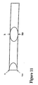
- Figure 11 shows a cross-section of a rectangular plate.
- Point A is where the user chooses to inject plastic
- point AA is the corresponding point on the other side of the surface.
- Point AA is automatically determined in accordance with the invention using the information from the classification of surfaces described above. Injection at this point ensures that the flow is matched on top and bottom surfaces.
- point B is the point chosen by the user and BB is the corresponding point determined by the method in accordance with the invention to ensure that flow is matched along top and bottom surfaces.
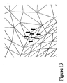
- FIG 12 shows an object composed of intersecting plates.
- the small arrow near the point of intersection of the plates indicates the user selected injection point.
- Figure 13 is an enlarged view of the injection area and shows the actual injection points required to allow the flow to emanate correctly from the selected point. In this case eight injection points are required one of which is supplied by the user and the other seven are determined by the invention.
- This method identifies which points need to be linked to the selected injection point with the concept of matching. For a given injection point specified by the user, a set consisting of all surfaces which are matched to all surfaces connected to the injection point is defined. The following steps are then performed:
- the injection flow rate is approximately double that for the volume of the object as each element in the surface mesh has a thickness equal to the gap thickness and so the mesh volume is approximately double that of the object.
- the time step for flow front advancement is determined by the geometric connectivity of the control volumes attached to each node.
- the solver has the ability to synchronize flow on matched surfaces during analysis.
- Figure 14 shows a cross-section of a plate where it is assumed that the flow front is advancing from the left and is leading a little on the top surface.
- each node may be empty, partially filled or filled.
- On each time step whether all the nodes belonging to an element are filled is checked. The instant this occurs the element is defined to be the current last element to fill and a line is drawn from its centroid to its matched element (the matched element is known from the surface classification described above) defining the check point. This "check line" is indicated in figure 14 . The nearest node to the check point is then assigned the same pressure as the last node to fill, as indicated in figure 14 .
- Flow synchronization is done for all matched surfaces and all elements near the flow front (on top and bottom surfaces) are checked at each time step.
- Synchronization is not performed on unmatched surfaces.
- FIG 15 An example highlighting the role of synchronization is shown in figure 15 , which shows the cross-section of a ribbed plate.
- the flow will split physically and fill the vertical rib as well as continuing to the right. Owing to the use of the surface mesh it is necessary to impose synchronization or the flow will continue up through node F to the top of the rib and then down to E and C. This is performed by using matching. Since the element comprising nodes D and F and the element comprising nodes C and E will be matched (as they are associated with matched surfaces) it is possible to assign the same pressures at nodes to synchronize the fronts. This is illustrated in Figure 16 .
- FIG 17 A sample result of the analysis according to the present invention is shown in figure 17 .
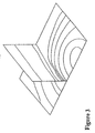
- This figure corresponds to figure 3 , which shows the results of the comparable, conventional analysis of the same solid model shown in figure 1 .
- the present invention uses a surface mesh rather than a midplane mesh, the results are displayed on the solid model ( figure 17 ) rather than on the midplane representation as in conventional analysis ( figure 3 ). Apart from being more natural for the operator, the display is visually more meaningful.
- linking may be performed in alternative methods such as, where multiple injection points are selected by a user, assigning the same flow rate to the linked nodes. It is to be understood, therefore, that this invention is not limited to the particular embodiments described by way of example hereinabove.
Abstract
Description
- This invention relates to a method for modelling solid objects, particularly for use in the simulation of fluid flow, to be used for example to simulate prototypes before production. In a preferred embodiment the method is used in the design of articles to be manufactured by injection molding, preferably from molten plastic materials.
- The modelling of solid objects is employed in various fields. Such modelling is used, for example, in the simulation of injection molding. In that field, it is widely recognized that the filling and packing phases of injection molding have a significant effect on the visual and mechanical properties of a molded object. Simulation is employed to analyse proposed shapes and injection points, and thus the final quality of the ultimate article. A requirement of any injection mold is that it can be filled with molten polymer given the pressure limits of a real injection molding machine. Simulation can provide information as to whether the mold can be filled and the fill pattern that will be achieved. By using simulation, it is possible to determine optimum gate locations and processing conditions. It is possible to predict the location of weld lines and air traps. Economic benefit is derived from simulation because problems can be predicted and solutions tested prior to the actual creation of the mold. This eliminates costly re-working and decreases the time required to get an object into production.
- Simulation technology has been developed and generally uses finite element/finite difference techniques to solve the governing equations of fluid flow and heat transfer. In order to minimize the time required for analysis and hence the required computer resources, the Hele-Shaw approximation is invoked to simplify the governing equations. It has been found that this simplification provides sufficient accuracy for injection molding but does create the need for specific modelling of the computational domain.
- Injection molding is an excellent process for repetitively manufacturing large numbers of objects or parts having complicated geometries. A characteristic of injection molded components is that the thickness of the wall is generally a small fraction of the overall length of the component. In view of the low thermal conductivity of plastics, this physical characteristic is essential to achieve the rapid cycle times that make the process so attractive.
- The flow of melt in an injection mold is determined by the familiar conservation laws of fluid mechanics. Solution of the equations in their full generality presents several practical problems. Owing to the characteristically thin walls of molded components, however, it is possible to make some reasonable assumptions that lead to a simplification of the governing equations. These simplified equations describe what is called Hele-Shaw flow and may be readily solved in complex geometries using an appropriate numerical technique such as the finite element and/or finite difference method.
- Injection molding simulation is now routinely regarded as a desirable aspect of plastic part design. Similarly, improved computer aided drafting (CAD) technology has led to the widespread use of surface and solid modelling. Associated advantages of this are the ability to better visualize an object, to use numerical cutting, and the possibility of achieving more concurrency in engineering design and manufacture. When using the Hele-Shaw approximation, plastic CAE analysis still requires the use of a surface model, representing the midplane of the real component, which is then meshed with triangular or quadrilateral elements to which suitable thicknesses are ascribed. The preparation of such a mesh can take a considerable amount of time, and requires substantial user input; owing to the labour intensive nature of this step, model preparation requires the greatest share of time when performing a molding simulation and makes this technique time consuming. In addition, as model preparation is an interactive task, it has a higher cost associated with it than simply running a computer program.
- Dan Deitz, in "Optimizing injection-molded parts" (Mechanical Engineering, 118(10) (1996) 89-90), discusses an automated process for creating a midplane mesh representation of a three-dimensional object. This approach is described as successful in most cases, but in some instances the resulting midplane required improvement by manual manipulation.
- This conventional technique for the simulation of three dimensional bodies is illustrated in
figures 1 to 3 of the accompanying drawings in which: -
Figure 1 is a representative example of an article to be manufactured by injection molding in the form of a T-shaped component; -
Figure 2 is a midplane representation of the component offigure 1 that is meshed; and -
Figure 3 is a view of the major results from a conventional analysis showing the position of the advancing melt at given times. - One solution to the above shortcomings is to avoid the use of the Hele-Shaw equations and solve the governing equations in their full generality. This has inherent problems owing to the thin walled nature of injection molded objects and parts. To perform such an analysis, the region representing the mold cavity into which molten polymer will be injected must be divided into small sub-domains called elements. Usually these elements are of tetrahedral or hexahedral shape. This process of subdivision is called meshing and the resultant network of tetrahedra or hexahedra the mesh.
-
EP 0 698 467 - Owing to the complicated shape of many injection molded objects and parts it is generally not possible to automatically mesh the cavity with hexahedral elements. It is possible, however, to mesh the domain automatically with tetrahedral elements. The thin walled nature of injection molded objects and parts means that the plastic is subject to a huge thermal gradient in the thickness direction of the component. This requires that there be a reasonable number of elements through the thickness. Using existing meshing technology, the result is a mesh consisting of hundreds of thousands or even millions of elements. The high number of elements makes the problem intractable for any but the fastest super computers. These are rarely found in industry, being extremely costly to purchase and maintain. Thus, although three dimensional simulation provides a solution that avoids the requirement of a midplane model, it is not as yet a practical solution.
- It is an object of the present invention, therefore, to provide a method for the simulation of flow in a three dimensional object that can produce simulations substantially automatically, without requiring the solution of the governing equations in their full generality.
- This object is achieved by a method according to claim 1.
- It should be noted that, in the context of the invention, generally opposed surfaces may be parallel, inclined to each other, meet at an acute angle or otherwise, and need not be planar, provided that a reasonable thickness or thicknesses may be assigned to the space between the surfaces.
- Preferably said injection point is linked to all locations from which flow may emanate from substantially the commencement of said flow analysis.
- Preferably said injection point remains so linked at substantially all times in said flow analysis subsequent to said linking.
- Thus, although the injection point must be linked to all these locations at some point in the flow analysis, and essentially continuously thereafter, the injection point may remain unlinked initially. Although this may decrease the accuracy of the final analysis adversely, it may nevertheless allow the analysis to yield useful results.
- Preferably said injection is one of a plurality of injection points.
- Preferably said synchronization of said flow fronts is checked periodically.
- Preferably said flow fronts are synchronized if found not to be or no longer synchronized.
- Preferably said checking is performed at each time step.
- More complex parts require synchronization at each calculational time step.
- Preferably said first and second generally opposed surfaces are one of a plurality of pairs of generally opposed surfaces.
- Thus, where the existing techniques utilize a single, midplane representation of the object in which flow is to be modelled, and perform a simulation with this representation, the method according to the present invention utilizes only the outer surfaces defining the three dimensional object to create a computational domain. These correspond to representations (in a preferred embodiment, meshed representations) of the domain in which flow is to be simulated, and would comprise, for example, meshed representations of the top and bottom surfaces of a part. Thus, in such an example the invention could be said to utilize an outer skin mesh rather than a midplane mesh. Elements of the two surfaces are matched, based on the ability to identify a thickness between such elements. An analysis, substantially along conventional lines (by means, for example, of the Hele-Shaw equations), is then performed of the flow in each of these domains in which flow is to be simulated, but linked to ensure fidelity with the physical reality being modelled.
- Preferably any unmatched elements of said first and second surfaces, being elements that could not be matched, are assigned thicknesses being the average of the thicknesses of adjacent matched elements where such adjacent matched elements exist, or of adjacent unmatched elements where such adjacent matched elements do not exist and said adjacent unmatched elements have been assigned thicknesses.
- Thus, eventually all matched and unmatched elements of the first and second surfaces may be assigned thicknesses.
- Preferably each element of an edge surface, being a surface between said first and second surfaces, and adjacent to either of said first or second surface is assigned a thickness proportional to the thickness of the element of said first or second surface to which said element of said edge surface is adjacent.
- Preferably each said element of an edge surface is assigned a thickness between 0.5 and 1.5 times said thickness of the element of said first or second surface to which said element of said edge surface is adjacent.
- Preferably each said element of an edge surface is assigned a thickness between 0.7 and 0.9 times said thickness of the element of said first or second surface to which said element of said edge surface is adjacent.
- Still more preferably each said element of an edge surface is assigned a thickness 0.75 times said thickness of the element of said first or second surface to which said element of said edge surface is adjacent.
- Preferably each element of an edge surface not adjacent to said first or second surface is assigned a thickness being the average of the thicknesses of adjacent elements of said edge surface that have been assigned thicknesses.
- Assigning a thickness, therefore, to every element of both surfaces and of edge surfaces ensures that the greatest accuracy will be achieved in the simulation.
- Preferably flow is simulated at a rate directly proportional to a desired flow rate for the object.
- The desired flow rate will usually be a flow rate selected by a user based simply on the volume of the object to be filled and the desired fill-time.
- Preferably said rate is proportional to the ratio of computational domain volume of said object to real volume of said object.
- More preferably said rate is substantially equal to the ratio of said computational domain volume to said real volume.
- This approach may be used to compensate for the modification of the effective volume of the object being modelled, owing to the use of two domains (for example, associated with the top and bottom surfaces), rather than one meshed domain as in the midplane approach. The computational domain volume is thus this effective volume used for the purposes of modelling the object, which most preferably will be approximately double the real volume.
- Preferably the method is performed with first and second representations of said first and second surfaces respectively comprising first and second meshes or lattices respectively, wherein said elements are interstices of said first and second meshes or lattices.
- Preferably said elements are triangular or quadrilateral.
- Preferably, when said elements are triangular, said elements are substantially equilateral.
- Preferably said method includes creating said first and second representations.
- In one embodiment the method includes creating improved representations of said first and second surfaces, whereby said elements are elements of said improved representations and said method is performed with said improved representations.
- Preferably said first and second representations are, or are a part of, a representation or representations for stereolithography of said object.
- Thus, computer representations of the two surfaces may be provided as input to the method, may be created by the method, or - if provided with representations of the surfaces - the method may create improved representations. As described above, particularly preferred representations include those with elements comprising equilateral triangles.
- In one embodiment of the invention the method described above is performed by a computer running a computer program encoding said method for simulating fluid flow.
- Preferably said method optionally includes corrections for non-isothermal temperature fields and/or non-Newtonian fluids.
- Thus, known techniques for including the effects of non-isothermal temperature fields and non-Newtonian fluids may be included so that more physically faithful simulations may be performed, as well as faster simulations without these corrections when speed is desirable, even at the expense of precision.
- In an embodiment of the present invention said injection point is linked to all locations on said first and second improved representations from which flow may emanate such that resulting flow fronts along said first and second improved representations are synchronized.
- Preferably the first and second representations are, or are a part of, a representation or representations for stereolithography of said object.
- Preferably the first and second improved representations comprise small equilateral triangular elements.
- According to a further broad aspect of the invention there is provided a computer provided with or running a computer program encoding the method for simulating fluid flow described above.
- In a further broad aspect of the invention there is provided a computer storage medium provided with a computer program embodying the method for simulating fluid flow described above.
- According to an embodiment of the present invention there is provided a method for simulating fluid flow within a three dimensional object having first and second generally opposed surfaces including:
- matching each element of said first surface with an element of said second surface between which a reasonable thickness may be defined, wherein matched elements of said first surface constitute a first set of matched elements and matched elements of said second surface constitute a second set of matched elements,
- specifying a fluid injection point,
- performing a flow analysis using each set of said matched elements, and
- synchronizing flow fronts resulting from said flow analysis along said first and second surfaces.
- Preferably said flow fronts are synchronized from substantially the commencement of said flow analysis.
- Alternatively said flow fronts are first synchronized after the commencement of said flow analysis.
- According to an embodiment of the present invention there is provided a method for simulating fluid flow within a three dimensional object having first and second generally opposed surfaces including:
- matching each element of said first surface with an element of said second surface between which a reasonable thickness may be defined, wherein matched elements of said first surface constitute a first set of matched elements and matched elements of said second surface constitute a second set of matched elements,
- specifying a fluid injection point,
- performing a flow analysis using said first set of matched elements,
- adapting said flow analysis to said second set of matched elements, and
- synchronizing flow fronts resulting from said flow analysis and said adaptation of said flow analysis along said first and second surfaces.
- Thus, it is possible in some cases to perform the method using only one of the sets of elements, and mapping the result onto the other set, and performing minor adaptation of the analysis to allow for any differences between the two surfaces.
- Preferably the method is performed with first and second representations of said first and second surfaces respectively comprising first and second meshes or lattices respectively, wherein said elements are interstices of said first and second meshes or lattices.
- Preferably the elements are triangular, and most preferably equilateral triangles.
- Preferably the elements are quadrilateral.
- Preferably the method includes creating said first and second representations, and more preferably creating improved representations, either from the original surfaces or from the first and second representations, and performing the method with elements of the representations or improved representations.
- In all the above methods according to the present invention aspects it is preferred that the synchronization comprises matching pressure and temperature.
- In an embodiment of the present invention the method includes specifying a plurality of fluid injection points, wherein said injection points are linked to all locations on said first and second surfaces from which flow may emanate such that resulting flow fronts along said first and second surfaces have matched flow rates.
- A preferred embodiment of the invention will be described, by way of example, with reference to the accompanying drawings, in which:
-
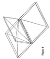
Figure 4 is an example of a stereolithography mesh of the T-shaped object offigure 1 ; -
Figure 5a shows an initial mesh used in a remeshing method according to the present invention; -
Figures 5b-f show the mesh offigure 5a progressively remeshed according to the remeshing method; -
Figure 6 shows the mesh offigure 4 , remeshed according to the preferred embodiment of the present invention; -
Figure 7a is a view of a mesh produced by conventional modelling techniques for a flat plate; -
Figure 7b is a view of a corresponding mesh produced for a flat plate according to a preferred embodiment of the present invention; -
Figure 8 illustrates surface matching for a flat plate according to the preferred embodiment; -
Figure 9 is a view similar tofigure 8 illustrating in cross-section the edges, matched surfaces and unmatched surfaces of another T-shaped object according to the preferred embodiment; -
Figure 10 is a cross-sectional view illustrating the edges, matched surfaces, matched tapered surfaces, unmatched surfaces and unmatched edges of yet another T-shaped object according to the preferred embodiment; -
Figure 11 is a view of a simple object showing injection points; -
Figure 12 is a view of an object comprising intersecting plates with a user selected injection point according to the preferred embodiment; -
Figure 13 is a enlarged view of the object offigure 12 showing the injection points required to allow flow to emanate correctly from the selected point according to the preferred embodiment; -
Figure 14 is a cross-section of a plate, with a flow front advancing from the left and leading a little on the top surface according to the preferred embodiment; -
Figure 15 illustrates in a cross-sectional view the synchronization of flow in a ribbed plate, with the flow splitting and also filling a vertical rib according to the preferred embodiment; -
Figure 16 illustrates in a cross-sectional view the assignment of identical pressures at nodes to synchronize flow fronts at a rib according to the preferred embodiment; and -
Figure 17 is a view similar tofigure 3 generated according to the preferred embodiment of the present invention. - A method for simulating fluid flow within a three dimensional object according to the present invention involves three main steps:
- 1) Preparation of geometry,
- 2) Selection of injection points, and
- 3) Analysis.
- A method in accordance with the present invention includes, therefore, a remeshing algorithm (or remesher) that uses as input the triangles from a stereolithography SLA (or similar) file and remeshes to produce a mesh that may be used in analysis.
- There are several steps involved in the input of a stereolithography mesh and its refinement into elements for analysis. These steps are:
- Input of mesh,
- Checking of mesh,
- Classification of mesh into surfaces, and
- Remeshing.
- In the preferred embodiment, the input mesh is of the form used for stereolithography. Alternatively, however, the input could be IGES surfaces (which would then be meshed internally), a surface mesh of quadrilaterals or a mix of quadrilaterals and triangles, tetrahedral or hexahedral meshes.
- The input mesh is checked to ensure that it is closed and orientable. The mesh is consistently oriented so that a unit normal to each element points outward from the internal volume defining the solid region that represents the object or part being modelled. The volume of this region and the surface area of the mesh are calculated and stored. The number of parts defined by the input mesh is also determined.
- The following properties for each element in the mesh are noted or calculated, and stored:
- Area,
- Normal at the element centroid,
- Edge lengths of the element,
- Internal angles at the vertices of the elements,
- Adjacent elements (the elements attached to each side of the element under consideration), and
- Bending angle between adjacent elements (the angle between normals of adjacent elements).
- Measure of minimum curvature (calculated by looking at the elements attached to a node and noting the angle between each adjacent pair of elements, whereby the measure of minimum curvature is then the smallest such angle between attached pairs of elements),
- Connecting elements (the set of elements connected to the node), and
- Number of edges connected to the node.
- planar surfaces, and
- low curvature surfaces.
- Length,
- Bending angle,
- Direction of bending (in or out), and
- Adjacent Elements.
- Length, and
- Edges connected to loop.
- Perimeter,
- Area,
- Nodes in surface,
- Elements in surface,
- Edges, and
- Minimum measure of curvature.
- With the surfaces classified, the mesh associated with each surface is refined using a bisection algorithm which bisects the longest side of a triangle and creates extra elements. This is illustrated in
figures 5a-f. Figure 5a shows the initial mesh. The mesh is refined by defining a node at the mid point of the longest element side and extending lines to vertices to define extra triangles. Infigures 5b to 5f , the midpoint of the longest side (denoted by o) and the dotted lines extending from this point define the new elements. Remeshing continues until the elements satisfy a criterion on size. - The result of the remeshing algorithm when applied to the mesh shown in
figure 4 is shown infigure 6 . In this regard the ideal triangle is equilateral: it may be seen that the triangles infigure 6 are far more uniform and closer to this ideal. - The method will thus accept as input stereolithography files (usually generated with a ".st1" filename extension) and other files that are similar such as "render" files (produced by "Pro-Engineer" with a ".slp" extension).
- In practice any file format that describes a mesh (of, for example, a lattice or quadrilaterals) covering the outer surfaces of the solid region may be used as input to the invention. The remesher is always used to improve the mesh quality and produce the triangular mesh for subsequent processing.
- The first step is then the preparation of the geometry, in which the geometry of the three dimensional CAD solid model is processed by conventional techniques to provide a surface mesh covering the outer surfaces of a solid body, rather than a midplane mesh as required by the conventional simulation approach. This distinction is depicted in
figures 7a and7b .Figure 7a shows the midplane mesh for a simple plate required by the conventional technique, whereasfigure 7b shows the mesh employed according to the present invention for the same object. Further, the flow front must be synchronized on both sides of the surface in which the material flows. If material is injected at the centre of the plate, then, in the conventional case, the material flows to the boundary of the part or object and stops without any difficulty. For the surface mesh on the solid model (figure 7b ) the material will flow to the outer edge, across the edge and then under the top surface. This is clearly not indicative of the physical phenomenon of flow in a plate and so, according to the invention, there are imposed some constraints on the flow when using the surface mesh. These constraints are that the injection point must link to all surfaces from which flow will emanate and the flow front must be synchronized along the top and bottom meshes of the surface mesh. Preferably this link is established from the commencement of the flow analysis, but a successful (if somewhat less accurate) analysis of the flow can still be performed is this linking commences subsequently. To perform these tasks the surface mesh must be categorized into surfaces which are then further classified to facilitate injection node selection and synchronization. Thus, according to the present invention, the surface mesh is then grouped into individual surfaces and classified. The categories of surfaces are: - Matched,
- Unmatched, and
- Edges.
-
Figure 9 further clarifies these concepts. This figure shows a cross-section through a filleted rib. Here ab, cd and gh are on edge surfaces. Lines aj and ed are matched to bc, fg and hi are matched and the curved sections ij and ef are unmatched. It should be noted that it is not possible to sensibly define a thickness of unmatched surfaces in the manner described above. As a final example,figure 10 illustrates a tapered rib cross-section. Here ab, cd and gh are edges as infigure 9 . Lines aj and ed are matched to line bc, and the curved lines ef and ij are unmatched as infigure 9 . However fg and hi are still considered matched despite the taper. Clearly, if the taper is extreme it is possible that the surfaces forming the tapered ribs may not be matched. - When surfaces have been classified it is possible to assign to elements on matched surfaces a thickness equal to the distance between the surfaces. Elements on edge surfaces are given the thickness of the matched surfaces to which they are attached. Finally elements on unmatched surfaces are given the average thickness of surrounding elements on matched surfaces.
- According to the present invention, the mesh on each side of the object is analyzed. A key aspect in this is obtaining a similar flow front on each side of the matched surfaces. As the entry point for flow is the injection node and is selected by the user, the method ensures that, regardless of where the user chooses to inject plastic, all matched surfaces near the point are tied to the injection node. "Tied" implies that the same pressure and temperature of melt at the injection node is given to all other tied nodes.
-
Figure 11 shows a cross-section of a rectangular plate. Point A is where the user chooses to inject plastic, point AA is the corresponding point on the other side of the surface. Point AA is automatically determined in accordance with the invention using the information from the classification of surfaces described above. Injection at this point ensures that the flow is matched on top and bottom surfaces. Similarly, point B is the point chosen by the user and BB is the corresponding point determined by the method in accordance with the invention to ensure that flow is matched along top and bottom surfaces. - The selection of injection node(s) can be quite complex. This is illustrated in
figure 12 , which shows an object composed of intersecting plates. The small arrow near the point of intersection of the plates indicates the user selected injection point.Figure 13 is an enlarged view of the injection area and shows the actual injection points required to allow the flow to emanate correctly from the selected point. In this case eight injection points are required one of which is supplied by the user and the other seven are determined by the invention. - This method identifies which points need to be linked to the selected injection point with the concept of matching. For a given injection point specified by the user, a set consisting of all surfaces which are matched to all surfaces connected to the injection point is defined. The following steps are then performed:
- 1. For each surface in this set, the point closest to the selected injection point is noted. These closest points form a set of points that are potentially to be linked to the user selected injection point.
- 2. Each member of the set of potential injection points is checked to see if it is already an injection point specified by the user. If it has already been so determined, it is omitted from the set.
- 3. For each potential injection point remaining, a set consisting of all surfaces which are matched to all surfaces connected to the potential injection point is defined.
- These steps are repeated until the set of potential points is unchanged. The set then forms the set of points to be linked to the user specified injection point.
- This procedure may be readily understood for the simple geometry of two crossed plates, for which the user specifies injection at the intersection of the plates. In the event that the surfaces connected to the specified injection point(s) are not matched to any other surfaces, no attempt is made to link other points to the injection point(s). Instead, flow is allowed to emanate until it reaches points attached to surfaces that are matched to opposing surfaces. The flow fronts are then synchronised on the opposing surfaces by assigning links between points on the opposing surfaces in a manner similar to that described above for linking points to the injection point.
- Analysis uses a Hele-Shaw type solver. The injection flow rate is approximately double that for the volume of the object as each element in the surface mesh has a thickness equal to the gap thickness and so the mesh volume is approximately double that of the object. The time step for flow front advancement is determined by the geometric connectivity of the control volumes attached to each node.
- The solver has the ability to synchronize flow on matched surfaces during analysis.
Figure 14 shows a cross-section of a plate where it is assumed that the flow front is advancing from the left and is leading a little on the top surface. By definition each node may be empty, partially filled or filled. On each time step, whether all the nodes belonging to an element are filled is checked. The instant this occurs the element is defined to be the current last element to fill and a line is drawn from its centroid to its matched element (the matched element is known from the surface classification described above) defining the check point. This "check line" is indicated infigure 14 . The nearest node to the check point is then assigned the same pressure as the last node to fill, as indicated infigure 14 . Flow synchronization is done for all matched surfaces and all elements near the flow front (on top and bottom surfaces) are checked at each time step. - Synchronization is not performed on unmatched surfaces.
- An example highlighting the role of synchronization is shown in
figure 15 , which shows the cross-section of a ribbed plate. The flow will split physically and fill the vertical rib as well as continuing to the right. Owing to the use of the surface mesh it is necessary to impose synchronization or the flow will continue up through node F to the top of the rib and then down to E and C. This is performed by using matching. Since the element comprising nodes D and F and the element comprising nodes C and E will be matched (as they are associated with matched surfaces) it is possible to assign the same pressures at nodes to synchronize the fronts. This is illustrated inFigure 16 . Here a line from the centroid of the element comprising nodes D and F is constructed to its matched element (comprising nodes C and E) to define the check point. As the nearest node to the check point is C, it is given the same pressure as node D for all subsequent time. Flow now emanates from node C as shown and so the flow goes up the rib on both sides as required. When establishing links for synchronization, links are only made to empty nodes to which are attached only empty nodes. - A sample result of the analysis according to the present invention is shown in
figure 17 . This figure corresponds tofigure 3 , which shows the results of the comparable, conventional analysis of the same solid model shown infigure 1 . As the present invention uses a surface mesh rather than a midplane mesh, the results are displayed on the solid model (figure 17 ) rather than on the midplane representation as in conventional analysis (figure 3 ). Apart from being more natural for the operator, the display is visually more meaningful. - Fundamental quantities calculated by the invention, therefore, include:
- the position of the melt front at any time (known as "filling contours"),
- the pressure at the injection node and the pressure distribution throughout the plastic at any time during filling or packing phases (known as a "pressure distribution"), and
- the temperature of the plastic melt at any point within the part at any time during filling or packing phases (known as a "temperature distribution").
- Thus, an increase in the speed of evaluating of proposed part shapes is achieved.
- Modifications within the scope of the invention may readily be effected by persons skilled in the art. For example, linking may be performed in alternative methods such as, where multiple injection points are selected by a user, assigning the same flow rate to the linked nodes. It is to be understood, therefore, that this invention is not limited to the particular embodiments described by way of example hereinabove.
Claims (34)
- A computer-implemented method for producing simulations of fluid flow within a three dimensional object, the method comprising:specifying first and second generally opposed surfaces of said object,matching each elements of said first surface with an element of said second surfaces between which a reasonable thickness may be defined, wherein matched elements of said first surface constitute a first set of matched elements and matched elements of said second surface constitute a second set of matched elements,specifying a fluid injection point,performing a flow analysis using each set of said matched elements, andsynchronizing flow fronts resulting from said flow analysis along said first and second surfaces,whereby the resulting flow fronts along said first and second surfaces are synchronized.
- A method as claimed in claim 1, further comprising forming first and second representations of said first and second surfaces, respectively, wherein said first and second representations comprise first and second meshes or lattices respectively, and wherein said elements are interstices of said first and second meshes or lattices.
- A method as claimed in either claim 1 or 2 wherein each element of each of said matched pairs of elements is assigned respectively said thickness.
- A method as claimed in any one of claims 1 to 3 wherein said flow fronts are first synchronized after the commencement of said flow analysis.
- A method as claimed in any one of the preceding claims wherein said injection point remains linked to locations on said first and second surfaces at substantially all times in said flow analysis subsequent to being first so linked.
- A method as claimed in claim 1, wherein performing said flow analysis using each set of said matched elements comprises performing a flow analysis using said first set of matched elements and adapting said flow analysis to said second set of matched elements.
- A method as claimed in claim 1 wherein performing said flow analysis comprises matching pressure or matching pressure and temperature.
- A method as claimed in claim 1 wherein said injection point is linked to all locations on said first and second surfaces from which flow may emanate.
- A method as claimed in claim 8 wherein said injection point is first linked to all said locations from substantially the commencement of said flow analysis.
- A method as claimed in either claim 8 or 9 wherein said injection point remains linked to all said locations at substantially all times in said flow analysis subsequent to being first so linked.
- A method as claimed in any one of the preceding claims wherein said injection point is one of a plurality of injection points.
- A method as claimed in any one of the preceding claims wherein synchronization of said flow fronts is checked periodically.
- A method as claimed in claim 12 wherein said checking is performed at each time step.
- A method as claimed in any one of the preceding claims wherein said flow fronts are synchronized if found not to be or no longer to be synchronized.
- A method as claimed in any one of the preceding claims wherein said first and second generally opposed surfaces are one of a plurality of pairs of generally opposed surfaces.
- A method as claimed in any one of the preceding claims wherein any unmatched elements of said first and second surfaces, being elements that could not be matched, are assigned thicknesses being the average of the thicknesses of adjacent matched elements where such adjacent matched elements exist, or of adjacent unmatched elements where such adjacent matched elements do not exist and said adjacent unmatched elements have been assigned thicknesses.
- A method as claimed in claim 16 wherein each element of an edge surface, being a surface between said first and second surfaces, and adjacent to either of said first or second surface is assigned a thickness proportional to the thickness of the element of said first or second surface to which said element of said edge surface is adjacent.
- A method as claimed in claim 17 wherein each said element of an edge surface is assigned a thickness between 0.5 and 1.5 times said thickness of the element of said first or second surface to which said element of said edge surface is adjacent.
- A method as claimed in claim 18 wherein each said element of an edge surface is assigned a thickness between 0.7 and 0.9 times said thickness of the element of said first or second surface to which said element of said edge surface is adjacent.
- A method as claimed in claim 17 wherein each element of an edge surface not adjacent to said first or second surface is assigned a thickness being the average of the thicknesses of adjacent elements of said edge surface that have been assigned thicknesses.
- A method as claimed in any one of the preceding claims wherein flow is simulated at a rate directly proportional to a desired flow rate for the object.
- A method as claimed in claim 21 wherein said rate is proportional to the ratio of computational domain volume of said object to real volume of said object.
- A method as claimed in claim 22 wherein said rate is substantially equal to the ratio of computational domain volume of said object to real volume of said object.
- A method as claimed in any one of the preceding claims wherein said method is performed with first and second representations of said first and second surfaces respectively comprising first and second meshes or lattices respectively, wherein said elements are interstices of said first and second meshes or lattices.
- A method as claimed in claim 24 wherein said method includes creating said first and second representations.
- A method as claimed in either claim 24 or 25 wherein said method includes creating improved representations of said first and second surfaces, whereby said elements are elements of said improved representations and said method is performed with said improved representations.
- A method as claimed in any one of claims 24 to 26 wherein said first and second representations are, or are a part of, a representation or representations for stereolithography of said object.
- A method as claimed in any one of the preceding claims wherein said elements are triangular or quadrilateral.
- A method as claimed in any one of the preceding claims wherein said method includes corrections for non-isothermal temperature fields and/or non-Newtonian fluids.
- A method as claimed in claim 1, comprising:providing or creating first and second representations of said first and second surfaces respectively;creating first and second improved representations from said first and second representations respectively;performing said method with said first and second improved representations of said respective surfaces, whereby each element of said first surface comprises a respective element of said first improved representation and each element of said second surface comprises a respective element of said second improved representation, so that matching each element of said first surface with an element of said second surface comprises matching each element of said first improved representation with an element of said second improved representation, said first set of matched elements comprise matched elements of said first improved representation, said second set of matched elements comprise matched elements of said first improved representation and said injection point is linked to all locations on said first and second improved representations from which flow may emanate such that resulting flow fronts along said first and second improved representations are synchronized.
- A method as claimed in claim 30, wherein said first and second representations are, or are a part of, a representation or representations for stereolithography of said object.
- A method of manufacturing an object having first and second generally opposed surfaces, including simulating fluid flow within said object according to the method of any one of the preceding claims.
- A computer program product stored on a computer readable medium adapted for causing a computer to perform the steps of the method of any one of claims 1 to 32.
- A computer readable medium, having a program recorded thereon, where the program is to make a computer execute a method defined in any one of claims 1 to 32.
Priority Applications (1)
| Application Number | Priority Date | Filing Date | Title |
|---|---|---|---|
| DE69829844.6T DE69829844T3 (en) | 1997-03-20 | 1998-02-27 | METHOD FOR MODELING THREE-DIMENSIONAL OBJECTS AND SIMULATION OF LIQUID FLOW |
Applications Claiming Priority (5)
| Application Number | Priority Date | Filing Date | Title |
|---|---|---|---|
| AUPO574697 | 1997-03-20 | ||
| AUPO5746A AUPO574697A0 (en) | 1997-03-20 | 1997-03-20 | Method for modelling three dimensional objects and simulation of fluid flow |
| US932125 | 1997-09-17 | ||
| US08/932,125 US6096088A (en) | 1997-03-20 | 1997-09-17 | Method for modelling three dimension objects and simulation of fluid flow |
| PCT/AU1998/000130 WO1998043179A1 (en) | 1997-03-20 | 1998-02-27 | Method for modelling three-dimensional objects and simulation of fluid flow |
Publications (4)
| Publication Number | Publication Date |
|---|---|
| EP0968473A1 EP0968473A1 (en) | 2000-01-05 |
| EP0968473A4 EP0968473A4 (en) | 2001-07-18 |
| EP0968473B1 EP0968473B1 (en) | 2005-04-20 |
| EP0968473B2 true EP0968473B2 (en) | 2015-12-02 |
Family
ID=25645378
Family Applications (1)
| Application Number | Title | Priority Date | Filing Date |
|---|---|---|---|
| EP98905149.5A Expired - Lifetime EP0968473B2 (en) | 1997-03-20 | 1998-02-27 | Method for modelling three-dimensional objects and simulation of fluid flow |
Country Status (13)
| Country | Link |
|---|---|
| EP (1) | EP0968473B2 (en) |
| JP (1) | JP4384266B2 (en) |
| CN (1) | CN1158619C (en) |
| AT (1) | ATE293812T1 (en) |
| BR (1) | BR9808026B1 (en) |
| CA (1) | CA2284002C (en) |
| DE (2) | DE69829844T3 (en) |
| ES (1) | ES2244047T3 (en) |
| HK (1) | HK1025822A1 (en) |
| ID (1) | ID24066A (en) |
| NZ (1) | NZ337718A (en) |
| PT (1) | PT968473E (en) |
| WO (1) | WO1998043179A1 (en) |
Families Citing this family (13)
| Publication number | Priority date | Publication date | Assignee | Title |
|---|---|---|---|---|
| NZ518409A (en) * | 1999-10-15 | 2002-10-25 | Moldflow Pty Ltd | Apparatus and method for structural analysis |
| DE60214696T2 (en) | 2002-07-23 | 2007-09-06 | Simcon Kunststofftechnische Software Gmbh | Simulation of liquid flow and structure analysis in thin-walled geometries |
| AU2003275236A1 (en) * | 2002-09-23 | 2004-04-08 | Optimum Power Technology, L.P. | Optimization expert system |
| AU2004211184A1 (en) | 2003-02-05 | 2004-08-26 | Moldflow Ireland Ltd. | Apparatus and methods for performing process simulation using a hybrid model |
| JP4068487B2 (en) | 2003-03-20 | 2008-03-26 | 株式会社日立製作所 | Shell model creation device for analysis |
| KR100889601B1 (en) | 2006-12-04 | 2009-03-20 | 한국전자통신연구원 | Ripple and foam creation apparatus and method using fluid particle data |
| JP4624467B2 (en) * | 2009-02-24 | 2011-02-02 | 株式会社バンダイナムコゲームス | Image processing apparatus, image processing method, and recording medium for processing three-dimensional computer graphics |
| TWI426463B (en) * | 2009-05-08 | 2014-02-11 | Hon Hai Prec Ind Co Ltd | Curved-surface rendering system and method |
| CN103294850A (en) * | 2013-04-27 | 2013-09-11 | 苏州市数字城市工程研究中心有限公司 | Intelligent simulation algorithm matching method for three-dimensional dynamic fluid |
| CN104339534A (en) * | 2013-08-08 | 2015-02-11 | 青岛佳友模具科技有限公司 | Injection molding method of superthick-wall transparent plastic parts |
| WO2017088134A1 (en) | 2015-11-25 | 2017-06-01 | Siemens Product Lifecycle Management Software Inc. | System and method for modeling of parts with lattice structures |
| DE102022104949A1 (en) | 2022-03-02 | 2023-09-07 | Ansys, Inc. | Methods and devices for generating a grid representation for three-dimensional objects |
| CN115906590B (en) * | 2023-01-05 | 2023-05-09 | 苏州数算软云科技有限公司 | Simulation filling method and device for injection molding and filling |
Citations (3)
| Publication number | Priority date | Publication date | Assignee | Title |
|---|---|---|---|---|
| US5189626A (en) † | 1991-03-27 | 1993-02-23 | Caterpillar Inc. | Automatic generation of a set of contiguous surface patches on a computer modeled solid |
| US5439622A (en) † | 1993-09-07 | 1995-08-08 | Motorola, Inc. | Method and apparatus for producing molded parts |
| US5572434A (en) † | 1994-06-14 | 1996-11-05 | Cornell Research Foundation, Inc. | Method for simulating mold filling of semi-solid material |
Family Cites Families (1)
| Publication number | Priority date | Publication date | Assignee | Title |
|---|---|---|---|---|
| TW305798B (en) * | 1994-08-01 | 1997-05-21 | Toray Industries |
-
1998
- 1998-02-27 PT PT98905149T patent/PT968473E/en unknown
- 1998-02-27 DE DE69829844.6T patent/DE69829844T3/en not_active Expired - Lifetime
- 1998-02-27 WO PCT/AU1998/000130 patent/WO1998043179A1/en active IP Right Grant
- 1998-02-27 CA CA002284002A patent/CA2284002C/en not_active Expired - Fee Related
- 1998-02-27 EP EP98905149.5A patent/EP0968473B2/en not_active Expired - Lifetime
- 1998-02-27 AT AT98905149T patent/ATE293812T1/en not_active IP Right Cessation
- 1998-02-27 JP JP54320898A patent/JP4384266B2/en not_active Expired - Lifetime
- 1998-02-27 ES ES98905149T patent/ES2244047T3/en not_active Expired - Lifetime
- 1998-02-27 NZ NZ337718A patent/NZ337718A/en not_active IP Right Cessation
- 1998-02-27 ID IDW991063D patent/ID24066A/en unknown
- 1998-02-27 CN CNB988034824A patent/CN1158619C/en not_active Expired - Lifetime
- 1998-02-27 BR BRPI9808026-1A patent/BR9808026B1/en not_active IP Right Cessation
- 1998-02-27 DE DE0968473T patent/DE968473T1/en active Pending
-
2000
- 2000-08-09 HK HK00104949A patent/HK1025822A1/en not_active IP Right Cessation
Patent Citations (3)
| Publication number | Priority date | Publication date | Assignee | Title |
|---|---|---|---|---|
| US5189626A (en) † | 1991-03-27 | 1993-02-23 | Caterpillar Inc. | Automatic generation of a set of contiguous surface patches on a computer modeled solid |
| US5439622A (en) † | 1993-09-07 | 1995-08-08 | Motorola, Inc. | Method and apparatus for producing molded parts |
| US5572434A (en) † | 1994-06-14 | 1996-11-05 | Cornell Research Foundation, Inc. | Method for simulating mold filling of semi-solid material |
Non-Patent Citations (11)
| Title |
|---|
| "Development of a radial flow analysis for injection molding" (Kazmer), published October 1991 † |
| D. DING ET AL.: "Finite element simulation of an injection moulding process", INTERNATIONAL JOURNAL FOR NUMERICAL, vol. 7, no. 7, 1997, pages 751 - 766 † |
| D.C. CONSTABLE ET AL.: "Three dimensional bi-component extrusion simulations by the boundary element method", COMPUTATIONAL MECHANICS, vol. 16, 1995, pages 114 - 123 † |
| J. KOPLIK: "Creeping flow in two-dimensional networks", JOURNAL FLUID MECH., vol. 119, 1982, pages 219 - 247 † |
| L. S. TURNG ET AL.: "On the Simulation of Microelectronic Encapsulation with Epoxy Molding Compound", ANTEC'92, pages 84 - 88 † |
| L.F.A. DOUVEN ET AL.: "The computation of properties of injection-moulded products", vol. 20, 1995, ELSEVIER SCIENCE LTD., pages: 403 - 457 † |
| M. A. IOANNIDIS ET AL.: "Network modelling of pore structure and transport properties of porous media", CHEMICAL ENGINEERING SCIENCE, vol. 48, no. 5, 1993, pages 951 - 972 † |
| R-Y- CHANG ET AL.: "A Unified K-BKZ Model for Residual Stress Analysis of Injection Molded Three-Dimensional Thin Shapes", POLYMER ENGINEERING AND SCIENCE, vol. 35, no. 22, November 1995 (1995-11-01), pages 1733 - 1747 † |
| R-Y CHANG ET AL.: "Integral Consitutive Model", 1994, HANSER PUBLISHERS, MUNICH, pages: 365 - 372 † |
| W. F. ZOETELIEF: "Multi-component Injection Moulding", 1995, CIP-DATA KONINKLIJKE BIBLIOTEK, DEN HAAG, pages: 1 - 127 † |
| Y.-E. YOO ET AL.: "Numerical simulation of the resin transfer mode filling process using the boundary element method", POLYMER COMPOSITES, vol. 17, no. 3, 1996, pages 368 - 374 † |
Also Published As
| Publication number | Publication date |
|---|---|
| HK1025822A1 (en) | 2000-11-24 |
| ID24066A (en) | 2000-07-06 |
| ATE293812T1 (en) | 2005-05-15 |
| DE69829844T2 (en) | 2006-03-02 |
| DE69829844T3 (en) | 2016-03-10 |
| EP0968473A1 (en) | 2000-01-05 |
| JP2001519069A (en) | 2001-10-16 |
| WO1998043179A1 (en) | 1998-10-01 |
| CA2284002C (en) | 2007-07-17 |
| BR9808026B1 (en) | 2011-04-19 |
| DE968473T1 (en) | 2001-04-05 |
| CN1158619C (en) | 2004-07-21 |
| BR9808026A (en) | 2000-03-08 |
| CN1251186A (en) | 2000-04-19 |
| EP0968473B1 (en) | 2005-04-20 |
| DE69829844D1 (en) | 2005-05-25 |
| ES2244047T3 (en) | 2005-12-01 |
| EP0968473A4 (en) | 2001-07-18 |
| CA2284002A1 (en) | 1998-10-01 |
| PT968473E (en) | 2005-08-31 |
| JP4384266B2 (en) | 2009-12-16 |
| NZ337718A (en) | 2000-02-28 |
Similar Documents
| Publication | Publication Date | Title |
|---|---|---|
| US6096088A (en) | Method for modelling three dimension objects and simulation of fluid flow | |
| US7574339B2 (en) | Automated generation of lean models for injection molding simulation | |
| JP2006518516A (en) | Apparatus and method for performing process simulation using a hybrid model | |
| EP0968473B2 (en) | Method for modelling three-dimensional objects and simulation of fluid flow | |
| CN100348403C (en) | Method and apparatus for modeling injection of fluid in mold cavity | |
| Wang et al. | Dynamic simulation and graphics for the injection molding of three-dimensional thin parts | |
| EP2612266B1 (en) | Interactive filling simulation on 3d injection molding models | |
| US8831913B2 (en) | Method of design optimisation | |
| EP1385103B1 (en) | Simulation of fluid flow and structural analysis within thin walled three dimensional geometries | |
| US20080100619A1 (en) | Mesh generation method and computer-readable article for executing the method | |
| US20020107676A1 (en) | Computer system for the analysis and design of extrusion devices | |
| AU721978B2 (en) | Method for modelling three-dimensional objects and simulation of fluid flow | |
| Wang et al. | Computer-aided mold design and manufacturing | |
| Dannelongue et al. | Three‐dimensional adaptive finite element computations and applications to non‐Newtonian fluids | |
| US20080294402A1 (en) | Method for analyzing fluid flow within a three-dimensional object | |
| Studer et al. | Numerical shape optimization as an approach to reduce material waste in injection molding | |
| Liang et al. | A finite element method for flow in compression molding of thin and thick parts | |
| Li | Modeling, design and control of vacuum assisted resin transfer molding (VARTM) for thickness variation reduction | |
| Wawrzynek et al. | A topological approach to modeling arbitrary crack propagation in 3D | |
| WO2020080175A1 (en) | Analysis device, analysis method, program, and storage medium | |
| Pop et al. | Reverse Engineering Tehnique Applied for Manufacturing Thin Wall Plastic Parts | |
| Petrovic et al. | Manufacturability analysis of injected parts based on a mid-surface approach | |
| Li | Development of integrated process design environment and statistical analysis of RTM process | |
| Tanguy et al. | A 3D mold filling study with significant heat effects | |
| Gajdoš et al. | SIMULATION ANALYSIS OF SINGLE SCREW EXTRUDER IN ANSYS POLYFLOW |
Legal Events
| Date | Code | Title | Description |
|---|---|---|---|
| PUAI | Public reference made under article 153(3) epc to a published international application that has entered the european phase |
Free format text: ORIGINAL CODE: 0009012 |
|
| 17P | Request for examination filed |
Effective date: 19990910 |
|
| AK | Designated contracting states |
Kind code of ref document: A1 Designated state(s): AT BE CH DE DK ES FI FR GB GR IE IT LI LU MC NL PT SE |
|
| EL | Fr: translation of claims filed | ||
| DET | De: translation of patent claims | ||
| A4 | Supplementary search report drawn up and despatched |
Effective date: 20010606 |
|
| AK | Designated contracting states |
Kind code of ref document: A4 Designated state(s): AT BE CH DE DK ES FI FR GB GR IE IT LI LU MC NL PT SE |
|
| RIC1 | Information provided on ipc code assigned before grant |
Free format text: 7G 06F 17/13 A, 7G 06F 17/50 B, 7B 29C 33/00 B, 7B 29C 45/02 B, 7B 29C 45/76 B, 7G 06T 17/20 B |
|
| 17Q | First examination report despatched |
Effective date: 20020307 |
|
| GRAP | Despatch of communication of intention to grant a patent |
Free format text: ORIGINAL CODE: EPIDOSNIGR1 |
|
| GRAS | Grant fee paid |
Free format text: ORIGINAL CODE: EPIDOSNIGR3 |
|
| GRAA | (expected) grant |
Free format text: ORIGINAL CODE: 0009210 |
|
| AK | Designated contracting states |
Kind code of ref document: B1 Designated state(s): AT BE CH DE DK ES FI FR GB GR IE IT LI LU MC NL PT SE |
|
| PG25 | Lapsed in a contracting state [announced via postgrant information from national office to epo] |
Ref country code: LI Free format text: LAPSE BECAUSE OF FAILURE TO SUBMIT A TRANSLATION OF THE DESCRIPTION OR TO PAY THE FEE WITHIN THE PRESCRIBED TIME-LIMIT Effective date: 20050420 Ref country code: CH Free format text: LAPSE BECAUSE OF FAILURE TO SUBMIT A TRANSLATION OF THE DESCRIPTION OR TO PAY THE FEE WITHIN THE PRESCRIBED TIME-LIMIT Effective date: 20050420 Ref country code: BE Free format text: LAPSE BECAUSE OF FAILURE TO SUBMIT A TRANSLATION OF THE DESCRIPTION OR TO PAY THE FEE WITHIN THE PRESCRIBED TIME-LIMIT Effective date: 20050420 |
|
| REG | Reference to a national code |
Ref country code: GB Ref legal event code: FG4D |
|
| REG | Reference to a national code |
Ref country code: CH Ref legal event code: EP |
|
| REG | Reference to a national code |
Ref country code: IE Ref legal event code: FG4D |
|
| REF | Corresponds to: |
Ref document number: 69829844 Country of ref document: DE Date of ref document: 20050525 Kind code of ref document: P |
|
| PG25 | Lapsed in a contracting state [announced via postgrant information from national office to epo] |
Ref country code: SE Free format text: LAPSE BECAUSE OF FAILURE TO SUBMIT A TRANSLATION OF THE DESCRIPTION OR TO PAY THE FEE WITHIN THE PRESCRIBED TIME-LIMIT Effective date: 20050720 Ref country code: GR Free format text: LAPSE BECAUSE OF FAILURE TO SUBMIT A TRANSLATION OF THE DESCRIPTION OR TO PAY THE FEE WITHIN THE PRESCRIBED TIME-LIMIT Effective date: 20050720 Ref country code: DK Free format text: LAPSE BECAUSE OF FAILURE TO SUBMIT A TRANSLATION OF THE DESCRIPTION OR TO PAY THE FEE WITHIN THE PRESCRIBED TIME-LIMIT Effective date: 20050720 |
|
| REG | Reference to a national code |
Ref country code: PT Ref legal event code: SC4A Effective date: 20050629 |
|
| REG | Reference to a national code |
Ref country code: CH Ref legal event code: PL |
|
| REG | Reference to a national code |
Ref country code: ES Ref legal event code: FG2A Ref document number: 2244047 Country of ref document: ES Kind code of ref document: T3 |
|
| PLBI | Opposition filed |
Free format text: ORIGINAL CODE: 0009260 |
|
| PLAX | Notice of opposition and request to file observation + time limit sent |
Free format text: ORIGINAL CODE: EPIDOSNOBS2 |
|
| PG25 | Lapsed in a contracting state [announced via postgrant information from national office to epo] |
Ref country code: GB Free format text: LAPSE BECAUSE OF NON-PAYMENT OF DUE FEES Effective date: 20060227 |
|
| PG25 | Lapsed in a contracting state [announced via postgrant information from national office to epo] |
Ref country code: MC Free format text: LAPSE BECAUSE OF NON-PAYMENT OF DUE FEES Effective date: 20060228 Ref country code: LU Free format text: LAPSE BECAUSE OF NON-PAYMENT OF DUE FEES Effective date: 20060228 |
|
| 26 | Opposition filed |
Opponent name: SIMPOE SAS Effective date: 20060116 |
|
| ET | Fr: translation filed | ||
| NLR1 | Nl: opposition has been filed with the epo |
Opponent name: SIMPOE SAS |
|
| PGFP | Annual fee paid to national office [announced via postgrant information from national office to epo] |
Ref country code: IE Payment date: 20060614 Year of fee payment: 9 |
|
| PLAF | Information modified related to communication of a notice of opposition and request to file observations + time limit |
Free format text: ORIGINAL CODE: EPIDOSCOBS2 |
|
| PLBB | Reply of patent proprietor to notice(s) of opposition received |
Free format text: ORIGINAL CODE: EPIDOSNOBS3 |
|
| GBPC | Gb: european patent ceased through non-payment of renewal fee |
Effective date: 20060227 |
|
| PLAY | Examination report in opposition despatched + time limit |
Free format text: ORIGINAL CODE: EPIDOSNORE2 |
|
| PLAH | Information related to despatch of examination report in opposition + time limit modified |
Free format text: ORIGINAL CODE: EPIDOSCORE2 |
|
| REG | Reference to a national code |
Ref country code: IE Ref legal event code: MM4A |
|
| PLBC | Reply to examination report in opposition received |
Free format text: ORIGINAL CODE: EPIDOSNORE3 |
|
| PG25 | Lapsed in a contracting state [announced via postgrant information from national office to epo] |
Ref country code: IE Free format text: LAPSE BECAUSE OF NON-PAYMENT OF DUE FEES Effective date: 20070227 |
|
| PLCK | Communication despatched that opposition was rejected |
Free format text: ORIGINAL CODE: EPIDOSNREJ1 |
|
| APAH | Appeal reference modified |
Free format text: ORIGINAL CODE: EPIDOSCREFNO |
|
| APBM | Appeal reference recorded |
Free format text: ORIGINAL CODE: EPIDOSNREFNO |
|
| APBP | Date of receipt of notice of appeal recorded |
Free format text: ORIGINAL CODE: EPIDOSNNOA2O |
|
| PGFP | Annual fee paid to national office [announced via postgrant information from national office to epo] |
Ref country code: ES Payment date: 20090317 Year of fee payment: 12 Ref country code: AT Payment date: 20090211 Year of fee payment: 12 |
|
| PGFP | Annual fee paid to national office [announced via postgrant information from national office to epo] |
Ref country code: PT Payment date: 20090223 Year of fee payment: 12 Ref country code: NL Payment date: 20090203 Year of fee payment: 12 Ref country code: FI Payment date: 20090212 Year of fee payment: 12 |
|
| APBQ | Date of receipt of statement of grounds of appeal recorded |
Free format text: ORIGINAL CODE: EPIDOSNNOA3O |
|
| PGFP | Annual fee paid to national office [announced via postgrant information from national office to epo] |
Ref country code: IT Payment date: 20090214 Year of fee payment: 12 |
|
| PLAB | Opposition data, opponent's data or that of the opponent's representative modified |
Free format text: ORIGINAL CODE: 0009299OPPO |
|
| PGFP | Annual fee paid to national office [announced via postgrant information from national office to epo] |
Ref country code: FR Payment date: 20090213 Year of fee payment: 12 |
|
| PLAB | Opposition data, opponent's data or that of the opponent's representative modified |
Free format text: ORIGINAL CODE: 0009299OPPO |
|
| R26 | Opposition filed (corrected) |
Opponent name: SIMPOE SAS Effective date: 20060116 |
|
| REG | Reference to a national code |
Ref country code: PT Ref legal event code: MM4A Free format text: LAPSE DUE TO NON-PAYMENT OF FEES Effective date: 20100827 |
|
| REG | Reference to a national code |
Ref country code: NL Ref legal event code: V1 Effective date: 20100901 |
|
| REG | Reference to a national code |
Ref country code: FR Ref legal event code: ST Effective date: 20101029 |
|
| PG25 | Lapsed in a contracting state [announced via postgrant information from national office to epo] |
Ref country code: FI Free format text: LAPSE BECAUSE OF NON-PAYMENT OF DUE FEES Effective date: 20100227 Ref country code: AT Free format text: LAPSE BECAUSE OF NON-PAYMENT OF DUE FEES Effective date: 20100227 |
|
| PG25 | Lapsed in a contracting state [announced via postgrant information from national office to epo] |
Ref country code: PT Free format text: LAPSE BECAUSE OF NON-PAYMENT OF DUE FEES Effective date: 20100827 Ref country code: NL Free format text: LAPSE BECAUSE OF NON-PAYMENT OF DUE FEES Effective date: 20100901 Ref country code: FR Free format text: LAPSE BECAUSE OF NON-PAYMENT OF DUE FEES Effective date: 20100301 |
|
| PG25 | Lapsed in a contracting state [announced via postgrant information from national office to epo] |
Ref country code: IT Free format text: LAPSE BECAUSE OF NON-PAYMENT OF DUE FEES Effective date: 20100227 |
|
| REG | Reference to a national code |
Ref country code: ES Ref legal event code: FD2A Effective date: 20110408 |
|
| PG25 | Lapsed in a contracting state [announced via postgrant information from national office to epo] |
Ref country code: ES Free format text: LAPSE BECAUSE OF NON-PAYMENT OF DUE FEES Effective date: 20110324 |
|
| PG25 | Lapsed in a contracting state [announced via postgrant information from national office to epo] |
Ref country code: ES Free format text: LAPSE BECAUSE OF NON-PAYMENT OF DUE FEES Effective date: 20100228 |
|
| APAH | Appeal reference modified |
Free format text: ORIGINAL CODE: EPIDOSCREFNO |
|
| PLAB | Opposition data, opponent's data or that of the opponent's representative modified |
Free format text: ORIGINAL CODE: 0009299OPPO |
|
| R26 | Opposition filed (corrected) |
Opponent name: SIMPOE SAS Effective date: 20060116 |
|
| APBU | Appeal procedure closed |
Free format text: ORIGINAL CODE: EPIDOSNNOA9O |
|
| PLAE | Information related to rejection of opposition modified |
Free format text: ORIGINAL CODE: 0009299REJO |
|
| D27O | Information related to the rejection of opposition deleted | ||
| PUAH | Patent maintained in amended form |
Free format text: ORIGINAL CODE: 0009272 |
|
| STAA | Information on the status of an ep patent application or granted ep patent |
Free format text: STATUS: PATENT MAINTAINED AS AMENDED |
|
| REG | Reference to a national code |
Ref country code: DE Ref legal event code: R082 Ref document number: 69829844 Country of ref document: DE Representative=s name: FLEUCHAUS & GALLO PARTNERSCHAFT MBB, DE |
|
| 27A | Patent maintained in amended form |
Effective date: 20151202 |
|
| AK | Designated contracting states |
Kind code of ref document: B2 Designated state(s): AT BE CH DE DK ES FI FR GB GR IE IT LI LU MC NL PT SE |
|
| REG | Reference to a national code |
Ref country code: DE Ref legal event code: R102 Ref document number: 69829844 Country of ref document: DE |
|
| PGFP | Annual fee paid to national office [announced via postgrant information from national office to epo] |
Ref country code: DE Payment date: 20170221 Year of fee payment: 20 |
|
| REG | Reference to a national code |
Ref country code: DE Ref legal event code: R071 Ref document number: 69829844 Country of ref document: DE |