EP0968685A2 - Device for treating bone fractures - Google Patents
Device for treating bone fractures Download PDFInfo
- Publication number
- EP0968685A2 EP0968685A2 EP99112136A EP99112136A EP0968685A2 EP 0968685 A2 EP0968685 A2 EP 0968685A2 EP 99112136 A EP99112136 A EP 99112136A EP 99112136 A EP99112136 A EP 99112136A EP 0968685 A2 EP0968685 A2 EP 0968685A2
- Authority
- EP
- European Patent Office
- Prior art keywords
- hole
- sleeve
- locking nail
- extension
- rotation pin
- Prior art date
- Legal status (The legal status is an assumption and is not a legal conclusion. Google has not performed a legal analysis and makes no representation as to the accuracy of the status listed.)
- Granted
Links
Images

Classifications
-
- A—HUMAN NECESSITIES
- A61—MEDICAL OR VETERINARY SCIENCE; HYGIENE
- A61B—DIAGNOSIS; SURGERY; IDENTIFICATION
- A61B17/00—Surgical instruments, devices or methods, e.g. tourniquets
- A61B17/56—Surgical instruments or methods for treatment of bones or joints; Devices specially adapted therefor
- A61B17/58—Surgical instruments or methods for treatment of bones or joints; Devices specially adapted therefor for osteosynthesis, e.g. bone plates, screws, setting implements or the like
- A61B17/68—Internal fixation devices, including fasteners and spinal fixators, even if a part thereof projects from the skin
- A61B17/74—Devices for the head or neck or trochanter of the femur
- A61B17/742—Devices for the head or neck or trochanter of the femur having one or more longitudinal elements oriented along or parallel to the axis of the neck
- A61B17/744—Devices for the head or neck or trochanter of the femur having one or more longitudinal elements oriented along or parallel to the axis of the neck the longitudinal elements coupled to an intramedullary nail
Definitions
- the invention relates to a device for supply of broken bones in the proximal part of the joint Femoral bone with one in the medullary bone of the femur insertable locking nail that in his upper area a transverse to its longitudinal axis Has through hole, with one in this Through hole in the axial direction fixed sleeve, which at one end protrudes beyond its outer jacket Carries external thread, and with one with one Shank immersed in the sleeve and in the sleeve axially displaceable femoral neck screw.
- Such devices are known for example from EP 0 727 189 B1 or EP 0 599 752 B1.
- This task is the beginning of a device described type according to the invention solved in that the through hole has a smooth cylindrical inner wall has on which the sleeve with her also smooth outer jacket fits tightly, and that the through hole a step-shaped in the locking nail Extension is upstream on its side wall at least one essentially in the circumferential direction has running rib, which when screwing the Sleeve into the through hole between the threads of the external thread of the sleeve engages.
- the through hole remains with this construction smooth over their entire length, and remains the same the outer circumference of the sleeve in the insertion area in the Through hole smooth, so that both parts with little Game can be performed exactly relative to each other.
- the locking nail does not experience any of this Weakening, a smooth continuous cylindrical bore is easy to manufacture.
- Laying down the sleeve takes place in that the external thread of the sleeve and the Rib or the ribs on the side wall of the extension interlock.
- This allows the sleeve to go into the through hole for as long be screwed in until the external thread on the Sleeve against the step of the step-like expansion strikes. This gives you a defined location of the Sleeve in the locking nail, in which the sleeve in the locking nail by engaging the rib or the Ribs in the external thread is securely fixed.
- the rib can be threaded through an internal thread the side wall be formed so that this two threads on the side wall on the one hand and on the Outside of the sleeve on the other hand when screwing in Interlock sleeve.
- the rib exactly in one plane runs perpendicular to the longitudinal axis of the through hole stands.
- the rib is not Part of a thread, so has no pitch on, nevertheless, such a rib can with appropriate Dimensioning between the threads of the external thread engage the sleeve and thereby the sleeve in axial Set direction.
- the enlargement extends over the entire circumference of the through hole, however, in a preferred embodiment provided that the extension was only one Part of the circumference of the through hole extends.
- the extension with a diagonally leading through the locking nail Through hole on the side of the through hole connects the farthest over a vertical one the plane of the longitudinal axis of the through hole protrudes.
- the through hole arranged at an angle a plane perpendicular to the longitudinal axis of the Through hole is located. This will make the through hole longer on one side than on the opposite Side, and on this longer side closes the step-like expansion in this configuration which therefore continues to be within the outer circumference of the locking nail remains.
- a second through hole in the locking nail is arranged, which has an anti-rotation pin records.
- This parallel to the locking screw running anti-rotation pen also penetrates into the bone fragment to be fixed and secure this therefore prevents rotation about the longitudinal axis the femoral neck screw.
- the thread can be designed so that there is only one Part of the second through opening extends so that the screw depth is limited by the fact that the end of the external thread of the anti-rotation pin against the End of the internal thread in the second through hole strikes.
- the anti-rotation pin has its length protruding from the locking nail smooth cylindrical outer wall on, so that an axial displacement between bone fragment on the one hand and Anti-rotation pin on the other hand is not hindered.
- the anti-rotation pin has a pointed end, that is if necessary, when the bone fragments approach in the course of the healing process also deeper into that Can dig in the bone fragment.
- the anti-rotation pin has an outer diameter which is significantly smaller than that of the sleeve, for example, this can be less than half Diameter of the sleeve.
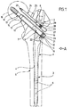
- the supply device shown in the drawing a femoral neck fracture includes a locking nail 1 with a cylindrical upper part 2 and an adjoining, tapered shaft 3.
- This locking nail 1 is in the medullary canal 4 of a femur bone 5 and inserted there through across the femur 5 screwed, not in the drawing shown screws set through cross holes 6 pass through in the area of the shaft 3. in the inserted state, the locking nail 1 is thereby recorded almost completely in the medullary canal 4.
- the Push shaft 3 across and opposite the longitudinal axis of the shaft 3 are inclined, for example around an angle of 50 °.
- the first through hole 7, which is closer to the shaft 3 lies, has a smooth, circular cylindrical inner wall 9 on, whose diameter over the entire length of the Through hole 7 is the same. Only at one end the through hole 7 increases the inner diameter the through hole 7 is stepped and forms thus an extension 10, the cylindrical inner wall 11 a plurality of ribs running parallel to one another 12 carries. This can be done by screwing one Be formed on the inner wall 11, the ribs can also be exactly in the circumferential direction run, i.e. without a slope in the longitudinal direction.
- the depth of the extension 10 is so small that the extension 10 due to the oblique course of the through hole 7 in the shaft 3 does not cover the entire Extends the peripheral region of the through hole 7, but only over the lower part, i.e. the part that is in immerses the outline of the shaft 3 on the opposite
- the through hole 7 ends with the smooth, cylindrical inner wall 9.
- the extension 10 thus forms in the illustrated Embodiment a trough-shaped depression on lower end of the otherwise completely cylindrical Through hole 7, and in this trough-shaped
- the ribs 12 are arranged in a recess.
- a possibly self-tapping bone thread 14 carries, which is a cylindrical Shaft 15 connects, the outer diameter clearly is smaller than the inner diameter of the inner wall 9 the through hole 7.
- the outside diameter of the bone thread 14 is chosen so that the locking screw 13 pushed through the through hole 7 and by means of a not shown in the drawing suitable tool in the to be fixed Bone fragment 16 can be screwed in.
- This sleeve 17 carries on the bone thread 14 facing away End of an external thread 18, the screw threads outwards via the cylindrical outer jacket 19 of the Project sleeve 17.
- depressions 21 are arranged, which is a turning tool, not shown in the drawing can record, with the help of the sleeve 17 can be rotated in the through hole 7.
- the screw-in depth of the sleeve 17 is limited.
- the sleeve 17 is practical in this construction along its entire length with the cylindrical Outer jacket 19 on the likewise cylindrical inner wall 9 of the through hole 7 and learns about it there optimal length, only in the area very in the longitudinal direction of the through hole short extension 10 there is an interference with the External thread 18, and thus the shaft 3 of the locking nail 1 in the exit area of the through hole 7 only slightly compared to a construction modified that no such extension with corresponding Ribs.
- the sleeve 17 is also very simply trained, its outer jacket is over the the entire length is of a cylindrical design, only in a short area is on this outer jacket the external thread 18 is attached.
- the second through hole 8 has one smaller diameter than the first through hole 7, for example, the inside diameter of the Through hole 8 smaller than 50% of the inner diameter the first through hole 7.
- the through hole 8 is from the insertion side developed gradually narrowing, expanded Part of it carries an internal thread 23, otherwise the inner walls executed smoothly.
- this second through hole 8 is an anti-rotation pin 24 screwed in, which is a smooth, cylindrical Has shaft 25 with a tip 26 and a adjoining, thickened cylindrical section 27, which in the transition area to the shaft 25 carries an external thread 28.
- the outside diameter of the Shank 25 corresponds to the inside diameter of the through hole 8 in the section with a smaller inner diameter, the outside diameter of the thickened section 27 of the anti-rotation pin 24, however, the outer diameter the second through hole 8 in the area with larger inner diameter.
- the anti-rotation pin 24 projects with its shaft 25 and its tip 26 into the bone fragment to be fixed 16 and prevents twisting of the bone fragment 16 around the longitudinal axis of the locking screw 13.
- the shaft 25 of the anti-rotation pin 24 is relatively thin and that the anti-rotation pin 24 with the tip 26 if necessary also deeper into the bone fragment 16 can dig in, is a relative displacement of the Bone fragment 16 to the anti-rotation pin 24 in the axial Direction possible, so that a possibly at Healing process approaching without further ado is possible.
Abstract
Um bei einer Vorrichtung zur Versorgung von Knochenbrüchen im gelenknahen proximalen Teil des Femurknochens mit einem in den Markraum des Femurknochens einsetzbaren Verriegelungsnagel, der in seinem oberen Bereich eine quer zu seiner Längsachse verlaufende Durchgangsbohrung aufweist, mit einer in dieser Durchgangsbohrung in axialer Richtung festgelegten Hülse, die an einem Ende ein über ihren Außenmantel überstehendes Außengewinde trägt, und mit einer mit einem Schaft in die Hülse eintauchenden und in der Hülse axial verschieblich aufgenommenen Schenkelhalsschraube, in einfachster Weise eine Festlegung der Hülse im Verriegelungsnagel zu ermöglichen, wird vorgeschlagen, daß die Durchgangsbohrung eine glatte zylindrische Innenwand aufweist, an der die Hülse mit ihrem ebenfalls glatten Außenmantel dicht anliegt, und daß der Durchgangsbohrung in dem Verriegelungsnagel eine stufenförmige Erweiterung vorgelagert ist, die an ihrer Seitenwand mindestens eine im wesentlichen in Umfangsrichtung verlaufende Rippe aufweist, die beim Einschrauben der Hülse in die Durchgangsbohrung zwischen die Gewindegänge des Außengewindes der Hülse eingreift. <IMAGE>In order to provide for a device for the treatment of bone fractures in the proximal part of the femur near the joint with a locking nail which can be inserted into the medullary cavity of the femur and which has in its upper region a through hole running transversely to its longitudinal axis, with a sleeve fixed in this through hole in the axial direction at one end carries an external thread protruding beyond its outer jacket, and with a femoral neck screw that dips into the sleeve and is axially displaceably received in the sleeve, to allow the sleeve to be fixed in the locking nail in the simplest manner, it is proposed that the through-hole be smooth Has cylindrical inner wall on which the sleeve lies tightly with its likewise smooth outer jacket, and that the through hole in the locking nail is preceded by a step-like extension, which at least one essentially in on its side wall Has circumferential rib which engages when screwing the sleeve into the through hole between the threads of the external thread of the sleeve. <IMAGE>
Description
Die Erfindung betrifft eine Vorrichtung zur Versorgung von Knochenbrüchen im gelenknahen proximalen Teil des Femurknochens mit einem in den Markraum des Femurknochens einsetzbaren Verriegelungsnagel, der in seinem oberen Bereich eine quer zu seiner Längsachse verlaufende Durchgangsbohrung aufweist, mit einer in dieser Durchgangsbohrung in axialer Richtung festgelegten Hülse, die an einem Ende ein über ihren Außenmantel überstehendes Außengewinde trägt, und mit einer mit einem Schaft in die Hülse eintauchenden und in der Hülse axial verschieblich aufgenommenen Schenkelhalsschraube.The invention relates to a device for supply of broken bones in the proximal part of the joint Femoral bone with one in the medullary bone of the femur insertable locking nail that in his upper area a transverse to its longitudinal axis Has through hole, with one in this Through hole in the axial direction fixed sleeve, which at one end protrudes beyond its outer jacket Carries external thread, and with one with one Shank immersed in the sleeve and in the sleeve axially displaceable femoral neck screw.
Derartige Vorrichtungen sind bekannt beispielsweise aus der EP 0 727 189 B1 oder der EP 0 599 752 B1.Such devices are known for example from EP 0 727 189 B1 or EP 0 599 752 B1.
Bei derartigen Vorrichtungen ist es notwendig, zur Stabilisierung der Knochenfragmente die Schenkelhalsschraube in der Hülse sicher zu führen, und zu diesem Zweck muß die Hülse im Verriegelungsnagel sicher festgelegt werden. Diese Hülse wird bei den bekannten Vorrichtungen erst über die Schenkelhalsschraube geschoben, wenn diese bereits in dem zu fixierenden Knochenfragment festgelegt ist, und daher müssen spezielle Vorrichtungen vorgesehen werden, um die Hülse nach dem Aufschieben auf die Schenkelhalsschraube im Verriegelungsnagel festzulegen.In such devices it is necessary to Stabilize the bone fragments the femoral neck screw to guide in the sleeve, and to this For this purpose, the sleeve must be securely fixed in the locking nail become. This sleeve is used in the known devices first pushed over the femoral neck screw, if this is already in the bone fragment to be fixed is set, and therefore need special Devices are provided to the sleeve after the Push on the femoral neck screw in the locking nail to be determined.
Bei der Vorrichtung gemäß EP 0 727 189 B1 erfolgt diese Festlegung durch eine in Längsrichtung in den Verriegelungsnagel einschraubbare Feststellschraube, die im Bereich von Umfangsrippen gegen die Außenwand der Hülse drückt. Dazu ist es notwendig, in den Verriegelungsnagel von oben her die Feststellschraube einzuschrauben, und dies erfordert einen erhöhten konstruktiven Aufwand, außerdem wird dadurch der Verriegelungsnagel gegebenenfalls geschwächt.This takes place in the device according to EP 0 727 189 B1 Fix in the longitudinal direction in the locking nail screw-in locking screw in the area of peripheral ribs against the outer wall of the sleeve presses. To do this, it is necessary in the locking nail screw in the locking screw from above, and this requires an increased design effort, in addition, the locking nail may become weakened.
Bei der Konstruktion gemäß EP 0 599 752 B1 wird die Hülse in die Durchgangsbohrung eingeschraubt, die zu diesem Zweck über ihre gesamte Länge mit einem Innengewinde versehen werden muß. Außerdem muß bei der bekannten Vorrichtung ein Anschlagbund an der Hülse vorgesehen werden, um deren Einschraubtiefe zu begrenzen.In the construction according to EP 0 599 752 B1, the Screwed sleeve into the through hole, which too for this purpose over its entire length with an internal thread must be provided. In addition, in the known Device provided a stop collar on the sleeve to limit their screwing depth.
Es ist Aufgabe der Erfindung, eine gattungsgemäße Vorrichtung so auszugestalten, daß ohne Schwächung des Verriegelungsnagels und mit möglichst wenig konstruktiven Anpassungen des Verriegelungsnagels und der Hülse eine sichere Festlegung der Hülse im Verriegelungsnagel erreichbar ist.It is an object of the invention to provide a generic device to design so that without weakening the Locking nail and with as little constructive as possible Adjustments to the locking nail and sleeve a secure fixing of the sleeve in the locking nail is achievable.
Diese Aufgabe wird bei einer Vorrichtung der eingangs beschriebenen Art erfindungsgemäß dadurch gelöst, daß die Durchgangsbohrung eine glatte zylindrische Innenwand aufweist, an der die Hülse mit ihrem ebenfalls glatten Außenmantel dicht anliegt, und daß der Durchgangsbohrung in dem Verriegelungsnagel eine stufenförmige Erweiterung vorgelagert ist, die an ihrer Seitenwand mindestens eine im wesentlichen in Umfangsrichtung verlaufende Rippe aufweist, die beim Einschrauben der Hülse in die Durchgangsbohrung zwischen die Gewindegänge des Außengewindes der Hülse eingreift. This task is the beginning of a device described type according to the invention solved in that the through hole has a smooth cylindrical inner wall has on which the sleeve with her also smooth outer jacket fits tightly, and that the through hole a step-shaped in the locking nail Extension is upstream on its side wall at least one essentially in the circumferential direction has running rib, which when screwing the Sleeve into the through hole between the threads of the external thread of the sleeve engages.
Bei dieser Konstruktion bleibt also die Durchgangsbohrung über ihre gesamte Länge glatt, und ebenso bleibt der Außenumfang der Hülse im Einsteckbereich in die Durchgangsbohrung glatt, so daß beide Teile mit geringem Spiel exakt relativ zueinander geführt werden können. Der Verriegelungsnagel erfährt dadurch keine Schwächung, eine glatt durchgehende zylindrische Bohrung ist einfach herzustellen. Die Festlegung der Hülse erfolgt dadurch, daß das Außengewinde der Hülse und die Rippe oder die Rippen auf der Seitenwand der Erweiterung ineinander eingreifen. Beim Einschrauben der Hülse in die Durchgangsbohrung kann die Hülse dadurch so lange eingeschraubt werden, bis das Außengewinde auf der Hülse gegen die Stufe der stufenförmigen Erweiterung anschlägt. Damit erhält man eine definierte Lage der Hülse im Verriegelungsnagel, in der die Hülse im Verriegelungsnagel durch den Eingriff der Rippe oder der Rippen in das Außengewinde sicher festgelegt ist.The through hole remains with this construction smooth over their entire length, and remains the same the outer circumference of the sleeve in the insertion area in the Through hole smooth, so that both parts with little Game can be performed exactly relative to each other. The locking nail does not experience any of this Weakening, a smooth continuous cylindrical bore is easy to manufacture. Laying down the sleeve takes place in that the external thread of the sleeve and the Rib or the ribs on the side wall of the extension interlock. When screwing in the sleeve This allows the sleeve to go into the through hole for as long be screwed in until the external thread on the Sleeve against the step of the step-like expansion strikes. This gives you a defined location of the Sleeve in the locking nail, in which the sleeve in the locking nail by engaging the rib or the Ribs in the external thread is securely fixed.
Die Rippe kann durch einen Gewindegang eines Innengewindes der Seitenwand gebildet sein, so daß diese beiden Gewinde an der Seitenwand einerseits und auf der Außenseite der Hülse andererseits beim Einachrauben der Hülse ineinander greifen.The rib can be threaded through an internal thread the side wall be formed so that this two threads on the side wall on the one hand and on the Outside of the sleeve on the other hand when screwing in Interlock sleeve.
Es kann aber bei einer anderen Ausführungsform auch vorgesehen sein, daß die Rippe exakt in einer Ebene verläuft, die senkrecht auf der Längsachse der Durchgangsbohrung steht. In diesem Falle ist die Rippe nicht Teil eines Gewindeganges, weist also keine Steigung auf, trotzdem kann eine solche Rippe bei entsprechender Bemessung zwischen die Gewindegänge des Außengewindes der Hülse eingreifen und die Hülse dadurch in axialer Richtung festlegen.But it can also in another embodiment be provided that the rib exactly in one plane runs perpendicular to the longitudinal axis of the through hole stands. In this case, the rib is not Part of a thread, so has no pitch on, nevertheless, such a rib can with appropriate Dimensioning between the threads of the external thread engage the sleeve and thereby the sleeve in axial Set direction.
Günstig ist es, wenn die Seitenwand der Erweiterung mehrere parallel zueinander verlaufende und nebeneinander liegende Rippen trägt, deren Abstand voneinander gleich ist. Es kann sich dabei sowohl um die Gewindegänge eines Gewindes handeln als auch um parallel zueinander verlaufende Rippen, die keine Steigung in Längsrichtung aufweisen.It is beneficial if the side wall of the extension several parallel to each other and side by side lying ribs carries their distance from each other is equal to. It can be both the threads a thread act as well as parallel to each other trending ribs that have no slope in Have longitudinal direction.
Grundsätzlich wäre es möglich, daß sich die Erweiterung über den gesamten Umfang der Durchgangsbohrung erstreckt, bei einer bevorzugten Ausführungsform ist jedoch vorgesehen, daß sich die Erweiterung nur über einen Teil des Umfanges der Durchgangsbohrung erstreckt.Basically, it would be possible that the enlargement extends over the entire circumference of the through hole, however, in a preferred embodiment provided that the extension was only one Part of the circumference of the through hole extends.
Insbesondere kann vorgesehen sein, daß die Erweiterung bei einer schräg durch den Verriegelungsnagel führenden Durchgangsbohrung an der Seite der Durchgangsbohrung anschließt, die am weitesten über eine senkrecht auf der Längsachse der Durchgangsbohrung stehenden Ebene hervorsteht. Bei einer schräg durch den Verriegelungsnagel führenden Durchgangsbohrung ist die Austrittsebene der Durchgangsbohrung im Winkel angeordnet zu einer Ebene, die senkrecht auf der Längsachse der Durchgangsbohrung liegt. Dadurch wird die Durchgangsbohrung auf einer Seite länger als auf der gegenüberliegenden Seite, und an dieser längeren Seite schließt sich bei dieser Ausgestaltung die stufenförmige Erweiterung an, die somit weiterhin innerhalb des Außenumfangs des Verriegelungsnagels bleibt. In particular, it can be provided that the extension with a diagonally leading through the locking nail Through hole on the side of the through hole connects the farthest over a vertical one the plane of the longitudinal axis of the through hole protrudes. At an angle through the locking nail leading through hole is the exit plane the through hole arranged at an angle a plane perpendicular to the longitudinal axis of the Through hole is located. This will make the through hole longer on one side than on the opposite Side, and on this longer side closes the step-like expansion in this configuration which therefore continues to be within the outer circumference of the locking nail remains.
Bei einer weiteren bevorzugten Ausführungsform der Erfindung ist vorgesehen, daß parallel zur Durchgangsbohrung eine zweite Durchgangsbohrung in dem Verriegelungsnagel angeordnet ist, welche einen Antirotationsstift aufnimmt. Dieser parallel zu der Verriegelungsschraube verlaufende Antirotationsstift dringt ebenfalls in das zu fixierende Knochenfragment ein und sichert dieses somit gegen eine Drehung um die Längsachse der Schenkelhalsschraube.In a further preferred embodiment of the invention it is intended that parallel to the through hole a second through hole in the locking nail is arranged, which has an anti-rotation pin records. This parallel to the locking screw running anti-rotation pen also penetrates into the bone fragment to be fixed and secure this therefore prevents rotation about the longitudinal axis the femoral neck screw.
Günstig ist es, wenn der Antirotationsstift in die zweite Durchgangsbohrung eingeschraubt ist, dadurch läßt er sich in dieser festlegen. Das Gewinde kann dabei so ausgebildet sein, daß es sich nur über einen Teil der zweiten Durchgangsöffnung erstreckt, so daß die Einschraubtiefe dadurch begrenzt wird, daß das Ende des Außengewindes des Antirotationsstiftes gegen das Ende des Innengewindes in der zweiten Durchgangsbohrung anschlägt.It is beneficial if the anti-rotation pin in the second through hole is screwed, thereby it can be specified in this. The thread can be designed so that there is only one Part of the second through opening extends so that the screw depth is limited by the fact that the end of the external thread of the anti-rotation pin against the End of the internal thread in the second through hole strikes.
Vorzugsweise weist der Antirotationsstift über seine aus dem Verriegelungsnagel hervorstehende Länge eine glatte zylindrische Außenwand auf, so daß eine Axialverschiebung zwischen Knochenfragment einerseits und Antirotationsstift andererseits nicht behindert wird.Preferably, the anti-rotation pin has its length protruding from the locking nail smooth cylindrical outer wall on, so that an axial displacement between bone fragment on the one hand and Anti-rotation pin on the other hand is not hindered.
Dies kann noch dadurch unterstützt werden, daß der Antirotationsstift ein spitzes Ende aufweist, sich also gegebenenfalls bei einer Annäherung der Knochenfragmente im Verlauf des Heilungsprozesses auch tiefer in das Knochenfragment eingraben kann. This can be supported by the anti-rotation pin has a pointed end, that is if necessary, when the bone fragments approach in the course of the healing process also deeper into that Can dig in the bone fragment.
Dieser Vorgang kann weiterhin dadurch unterstützt werden, daß der Antirotationsstift einen Außendurchmesser aufweist, der wesentlich kleiner ist als der der Hülse, beispielsweise kann dieser kleiner sein als der halbe Durchmesser der Hülse.This process can still be supported by that the anti-rotation pin has an outer diameter which is significantly smaller than that of the sleeve, for example, this can be less than half Diameter of the sleeve.
Die nachfolgende Beschreibung bevorzugter Ausführungsformen der Erfindung dient im Zusammenhang mit der Zeichnung der näheren Erläuterung. Es zeigen:
- Figur 1:
- eine Längsschnittansicht einer in den Femur eingesetzten Verriegelungsvorrichtung und
- Figur 2:
- eine Ansicht des Verriegelungsnagels der
Vorrichtung der
Figur 1 in Richtung des Pfeiles A inFigur 1.
- Figure 1:
- a longitudinal sectional view of a locking device used in the femur and
- Figure 2:
- 2 shows a view of the locking nail of the device of FIG. 1 in the direction of arrow A in FIG. 1.
Die in der Zeichnung dargestellte Vorrichtung zur Versorgung
eines Oberschenkelhalsbruches umfaßt einen Verriegelungsnagel
1 mit einem zylindrischen Oberteil 2
und einem sich daran anschließenden, verjüngten Schaft
3. Dieser Verriegelungsnagel 1 wird in den Markraum 4
eines Femurknochens 5 eingesetzt und dort durch quer in
den Femurknochen 5 eingedrehte, in der Zeichnung nicht
dargestellte Schrauben festgelegt, die durch Querbohrungen
6 im Bereich des Schaftes 3 hindurchtreten. Im
eingesetzten Zustand wird der Verriegelungsnagel 1 dadurch
praktisch vollständig im Markraum 4 aufgenommen.The supply device shown in the drawing
a femoral neck fracture includes a
Im Schaft 3 sind nebeneinander zwei parallel verlaufende
Durchgangsbohrungen 7 und 8 angeordnet, die den
Schaft 3 quer durchsetzen und gegenüber der Längsachse
des Schaftes 3 schräg geneigt sind, beispielsweise um
einen Winkel von 50°.In the
Die erste Durchgangsbohrung 7, die näher am Schaft 3
liegt, weist eine glatte, kreiszylindrische Innenwand 9
auf, deren Durchmesser über die gesamte Länge der
Durchgangsbohrung 7 gleich ist. Lediglich an einem Ende
der Durchgangsbohrung 7 vergrößert sich der Innendurchmesser
der Durchgangsbohrung 7 stufenförmig und bildet
somit eine Erweiterung 10 aus, deren zylindrische Innenwand
11 mehrere parallel zueinander verlaufende Rippen
12 trägt. Diese können durch die Schraubgänge eines
Innengewindes auf der Innenwand 11 ausgebildet sein,
die Rippen können aber auch genau in Umfangsrichtung
verlaufen, also ohne Steigung in Längsrichtung.The first through
Die Tiefe der Erweiterung 10 ist so gering, daß die Erweiterung
10 aufgrund des schrägen Verlaufs der Durchgangsbohrung
7 im Schaft 3 sich nicht über den gesamten
Umfangsbereich der Durchgangsbohrung 7 erstreckt, sondern
nur über den unteren Teil, also den Teil, der in
den Umriß des Schaftes 3 eintaucht, auf der gegenüberliegenden
Seite endet dagegen die Durchgangsbohrung 7
mit der glatten, zylindrischen Innenwand 9.The depth of the
Die Erweiterung 10 bildet also bei dem dargestellten
Ausführungsbeispiel eine muldenförmige Vertiefung am
unteren Ende der ansonsten vollständig zylindrischen
Durchgangsbohrung 7 aus, und in dieser muldenförmigen
Vertiefung sind die Rippen 12 angeordnet. The
Durch die Durchgangsbohrung 7 wird eine Verriegelungsschraube
13 hindurchgeschoben, die an ihrem kopfseitigen
Ende ein gegebenenfalls selbstschneidendes Knochengewinde
14 trägt, an welches sich ein zylindrischer
Schaft 15 anschließt, dessen Außendurchmesser deutlich
kleiner ist als der Innendurchmesser der Innenwand 9
der Durchgangsbohrung 7. Der Außendurchmesser des Knochengewindes
14 ist so gewählt, daß die Verriegelungsschraube
13 durch die Durchgangsbohrung 7 hindurchgeschoben
und mittels eines in der Zeichnung nicht dargestellten
geeigneten Werkzeuges in das zu fixierende
Knochenfragment 16 eingeschraubt werden kann.Through the
Über den zylindrischen Schaft 15 der in dieser Weise
eingeschraubten Verriegelungsschraube 13 wird eine Hülse
17 geschoben, deren Innendurchmesser dem Außendurchmesser
des Schaftes 15 entspricht und deren Außendurchmesser
dem Innendurchmesser der Durchgangsbohrung 7
entspricht. Die Hülse 17 füllt somit den Zwischenraum
zwischen dem Schaft 15 der Verriegelungsschraube 13 und
der Innenwand 9 der Durchgangsbohrung 7 aus.About the
Diese Hülse 17 trägt an ihrem dem Knochengewinde 14 abgewandten
Ende ein Außengewinde 18, dessen Schraubgänge
nach außen über den zylindrischen Außenmantel 19 der
Hülse 17 hervorstehen. An der dem Außengewinde 18 benachbarten
Stirnkante 20 sind Vertiefungen 21 angeordnet,
die ein in der Zeichnung nicht dargestelltes Drehwerkzeug
aufnehmen können, mit dessen Hilfe die Hülse
17 in der Durchgangsbohrung 7 verdreht werden kann. Bei
diesem Verdrehen greifen das Außengewinde 18 auf der
Hülse 17 und die Rippen 12 in der Erweiterung 10 ineinander,
bis das vordere Ende des Außengewindes 18 an der
Stufe 22 anschlägt, die zwischen der Innenwand 9 der
Durchgangsbohrung 7 einerseits und der Innenwand 11 der
Erweiterung 10 andererseits ausgebildet ist. Dadurch
wird die Einschraubtiefe der Hülse 17 begrenzt.This
Die Hülse 17 liegt bei dieser Konstruktion somit praktisch
über ihre gesamte Länge mit dem zylindrischen
Außenmantel 19 an der ebenfalls zylindrischen Innenwand
9 der Durchgangsbohrung 7 an und erfährt dort über ihre
gesamte Länge eine optimale Führung, lediglich im Bereich
der in Längsrichtung der Durchgangsbohrung sehr
kurzen Erweiterung 10 ergibt sich ein Eingriff mit dem
Außengewinde 18, und damit ist der Schaft 3 des Verriegelungsnagels
1 im Austrittsbereich der Durchgangsbohrung
7 nur geringfügig gegenüber einer Konstruktion
modifiziert, die keine derartige Erweiterung mit entsprechenden
Rippen aufweist. Die Hülse 17 ist ebenfalls
sehr einfach ausgebildet, ihr Außenmantel ist über die
gesamte Länge gleichbleibend zylindrisch ausgebildet,
lediglich in einem kurzen Bereich ist auf diesen Außenmantel
das Außengewinde 18 aufgesetzt.The
Die zweite Durchgangsbohrung 8 weist einen wesentlich
kleineren Durchmesser auf als die erste Durchgangsbohrung
7, beispielsweise kann der Innendurchmesser der
Durchgangsbohrung 8 kleiner als 50% des Innendurchmessers
der ersten Durchgangsbohrung 7 sein.The second through
Die Durchgangsbohrung 8 ist dabei von der Einschubseite
her sich stufig verengend ausgebildet, im erweiterten
Teil trägt sie ein Innengewinde 23, sonst sind die Innenwände
glatt ausgeführt. The through
In diese zweite Durchgangsbohrung 8 ist ein Antirotationsstift
24 eingeschraubt, der einen glatten, zylindrischen
Schaft 25 mit einer Spitze 26 aufweist und einen
sich daran anschließenden, verdickten zylindrischen Abschnitt
27, der im Übergangsbereich zu dem Schaft 25
ein Außengewinde 28 trägt. Der Außendurchmesser des
Schaftes 25 entspricht dem Innendurchmesser der Durchgangsbohrung
8 im Abschnitt mit geringerem Innendurchmesser,
der Außendurchmesser des verdickten Abschnittes
27 des Antirotationsstiftes 24 dagegen dem Außendurchmesser
der zweiten Durchgangsbohrung 8 im Bereich mit
größerem Innendurchmesser. Beim Einschrauben des Antirotationsstiftes
24 in die Durchgangsbohrung 8 stößt
das Außengewinde 28 gegen die Stufe 29 in der Durchgangsbohrung
8 und begrenzt somit die Einschraubtiefe.In this second through
Der Antirotationsstift 24 ragt mit seinem Schaft 25 und
seiner Spitze 26 in das zu fixierende Knochenfragment
16 hinein und verhindert somit eine Verdrehung des Knochenfragmentes
16 um die Längsachse der Verriegelungsschraube
13. Dadurch, daß der Schaft 25 des Antirotationsstiftes
24 relativ dünn ausgebildet ist und dadurch,
daß sich der Antirotationsstift 24 mit der Spitze
26 gegebenenfalls auch tiefer in das Knochenfragment
16 eingraben kann, ist eine Relativverschiebung des
Knochenfragmentes 16 zum Antirotationsstift 24 in axialer
Richtung möglich, so daß eine gegebenenfalls beim
Heilungsprozeß auftretende Annäherung ohne weiteres
möglich ist.The
Claims (11)
Applications Claiming Priority (2)
| Application Number | Priority Date | Filing Date | Title |
|---|---|---|---|
| DE19829228 | 1998-06-30 | ||
| DE1998129228 DE19829228C1 (en) | 1998-06-30 | 1998-06-30 | Bone fracture fixture with locking-nail with through-hole |
Publications (3)
| Publication Number | Publication Date |
|---|---|
| EP0968685A2 true EP0968685A2 (en) | 2000-01-05 |
| EP0968685A3 EP0968685A3 (en) | 2002-03-27 |
| EP0968685B1 EP0968685B1 (en) | 2004-09-01 |
Family
ID=7872536
Family Applications (1)
| Application Number | Title | Priority Date | Filing Date |
|---|---|---|---|
| EP19990112136 Expired - Lifetime EP0968685B1 (en) | 1998-06-30 | 1999-06-24 | Device for treating bone fractures |
Country Status (3)
| Country | Link |
|---|---|
| EP (1) | EP0968685B1 (en) |
| DE (1) | DE19829228C1 (en) |
| ES (1) | ES2226239T3 (en) |
Cited By (13)
| Publication number | Priority date | Publication date | Assignee | Title |
|---|---|---|---|---|
| DE20219683U1 (en) * | 2002-12-19 | 2004-04-29 | Stryker Trauma Gmbh | osteosynthesis |
| US6835197B2 (en) | 2001-10-17 | 2004-12-28 | Christoph Andreas Roth | Bone fixation system |
| JP2008068011A (en) * | 2006-09-15 | 2008-03-27 | Japan Medical Materials Corp | Fixing appliance for bone fracture of proximal part of femur |
| US7892234B2 (en) | 2004-06-22 | 2011-02-22 | Synthes Usa, Llc | Intramedullary nail |
| US8066706B2 (en) | 2004-06-30 | 2011-11-29 | Synthes Usa, Llc | Surgical nail |
| US8114079B2 (en) | 2008-03-31 | 2012-02-14 | Depuy Products, Inc. | Intramedullary nail with coupled shafts |
| US8221419B2 (en) | 2003-08-29 | 2012-07-17 | Synthes Usa, Llc | Intramedullary nail |
| US8465489B2 (en) | 2003-06-12 | 2013-06-18 | Synthes Usa, Llc | Surgical nail |
| US8641740B2 (en) | 2007-09-26 | 2014-02-04 | Zimmer, Gmbh | Bone anchoring device for the operative repair of fractures |
| US8888779B2 (en) | 2003-03-07 | 2014-11-18 | DePuy Synthes Products, LLC | Locking screw for an intramedullary nail |
| US8939978B2 (en) | 2007-03-20 | 2015-01-27 | Smith & Nephew, Inc. | Orthopaedic plate and screw assembly |
| US9237909B2 (en) | 2003-07-30 | 2016-01-19 | DePuy Synthes Products, Inc. | Surgical nail |
| US9737347B2 (en) | 2003-06-12 | 2017-08-22 | DePuy Synthes Products, Inc. | Surgical nail |
Families Citing this family (14)
| Publication number | Priority date | Publication date | Assignee | Title |
|---|---|---|---|---|
| DE20113345U1 (en) | 2001-08-17 | 2003-01-02 | Tantum Ag | Femurfrakturnagel |
| AU2002328245A1 (en) * | 2002-10-03 | 2004-04-23 | Synthes Ag Chur | Device for bone fixation |
| DE10305348A1 (en) * | 2003-02-10 | 2004-08-26 | Cell Center Cologne Gmbh | Dynamic epiphyseal telescopic screw |
| US7455673B2 (en) * | 2003-07-08 | 2008-11-25 | Yechiel Gotfried | Intramedullary nail system and method for fixation of a fractured bone |
| US7799030B2 (en) | 2003-09-08 | 2010-09-21 | Smith & Nephew, Inc. | Orthopaedic plate and screw assembly |
| US20050055024A1 (en) | 2003-09-08 | 2005-03-10 | James Anthony H. | Orthopaedic implant and screw assembly |
| US7780667B2 (en) | 2003-09-08 | 2010-08-24 | Smith & Nephew, Inc. | Orthopaedic plate and screw assembly |
| CA2539488C (en) * | 2003-09-18 | 2011-11-08 | Synthes Gmbh | Device for the treatment of femoral fractures |
| DE102005039854B4 (en) * | 2005-08-23 | 2007-07-12 | Königsee Implantate und Instrumente zur Osteosynthese GmbH | Proximal femoral nail |
| US8100911B2 (en) | 2008-06-30 | 2012-01-24 | Depuy Products, Inc. | Fracture fixation apparatus |
| US8449544B2 (en) | 2009-06-30 | 2013-05-28 | Smith & Nephew, Inc. | Orthopaedic implant and fastener assembly |
| BRPI1011556A2 (en) | 2009-06-30 | 2016-03-29 | Smith & Nephew Inc | orthopedic implant and fixation assembly |
| US9895177B2 (en) | 2016-01-15 | 2018-02-20 | ARTHREX, GmbH | Bone fixation device for treatment of femoral fractures |
| BR112019007255B1 (en) * | 2016-10-10 | 2022-10-04 | Francisco Ferrero Manzanal | VARIABLE ANGLE INTRAMEDULAR FIXATION SYSTEM TO TREAT FEMURAL FRACTURES |
Citations (2)
| Publication number | Priority date | Publication date | Assignee | Title |
|---|---|---|---|---|
| EP0599752B1 (en) | 1992-11-24 | 1997-04-23 | Fixano Sa | Osteosynthesis device for trochanteric or intertrochanteric fractures |
| EP0727189B1 (en) | 1995-02-18 | 1998-04-01 | Aesculap Ag | Device for treating bone fractures |
Family Cites Families (2)
| Publication number | Priority date | Publication date | Assignee | Title |
|---|---|---|---|---|
| IT1272537B (en) * | 1993-08-30 | 1997-06-23 | Synos Medical Spa | ENDOMIDOLLAR NAIL FOR THE SYNTHESIS OF THE PROXIMAL FEMORE FRACTURES AND EQUIPMENT FOR ITS POSITIONING |
| DE29709725U1 (en) * | 1997-06-04 | 1997-08-21 | Aesculap Ag & Co Kg | Implant |
-
1998
- 1998-06-30 DE DE1998129228 patent/DE19829228C1/en not_active Expired - Lifetime
-
1999
- 1999-06-24 EP EP19990112136 patent/EP0968685B1/en not_active Expired - Lifetime
- 1999-06-24 ES ES99112136T patent/ES2226239T3/en not_active Expired - Lifetime
Patent Citations (2)
| Publication number | Priority date | Publication date | Assignee | Title |
|---|---|---|---|---|
| EP0599752B1 (en) | 1992-11-24 | 1997-04-23 | Fixano Sa | Osteosynthesis device for trochanteric or intertrochanteric fractures |
| EP0727189B1 (en) | 1995-02-18 | 1998-04-01 | Aesculap Ag | Device for treating bone fractures |
Cited By (19)
| Publication number | Priority date | Publication date | Assignee | Title |
|---|---|---|---|---|
| US9918757B2 (en) | 2001-10-17 | 2018-03-20 | DePuy Synthes Products, Inc. | Bone fixation system |
| US6835197B2 (en) | 2001-10-17 | 2004-12-28 | Christoph Andreas Roth | Bone fixation system |
| US7182765B2 (en) | 2001-10-17 | 2007-02-27 | Synthes (Usa) | Bone fixation system |
| US7306600B2 (en) | 2001-10-17 | 2007-12-11 | Synthes (U.S.A.) | Bone fixation system |
| US10271881B2 (en) | 2001-10-17 | 2019-04-30 | DePuy Synthes Products, Inc. | Bone fixation system |
| DE20219683U1 (en) * | 2002-12-19 | 2004-04-29 | Stryker Trauma Gmbh | osteosynthesis |
| US7569055B2 (en) | 2002-12-19 | 2009-08-04 | Stryker Trauma Gmbh | Osteosynthetic aid |
| US8888779B2 (en) | 2003-03-07 | 2014-11-18 | DePuy Synthes Products, LLC | Locking screw for an intramedullary nail |
| US9737347B2 (en) | 2003-06-12 | 2017-08-22 | DePuy Synthes Products, Inc. | Surgical nail |
| US8465489B2 (en) | 2003-06-12 | 2013-06-18 | Synthes Usa, Llc | Surgical nail |
| US9237909B2 (en) | 2003-07-30 | 2016-01-19 | DePuy Synthes Products, Inc. | Surgical nail |
| US8221419B2 (en) | 2003-08-29 | 2012-07-17 | Synthes Usa, Llc | Intramedullary nail |
| US9814500B2 (en) | 2003-08-29 | 2017-11-14 | DePuy Synthes Products, Inc. | Intramedullary nail |
| US7892234B2 (en) | 2004-06-22 | 2011-02-22 | Synthes Usa, Llc | Intramedullary nail |
| US8066706B2 (en) | 2004-06-30 | 2011-11-29 | Synthes Usa, Llc | Surgical nail |
| JP2008068011A (en) * | 2006-09-15 | 2008-03-27 | Japan Medical Materials Corp | Fixing appliance for bone fracture of proximal part of femur |
| US8939978B2 (en) | 2007-03-20 | 2015-01-27 | Smith & Nephew, Inc. | Orthopaedic plate and screw assembly |
| US8641740B2 (en) | 2007-09-26 | 2014-02-04 | Zimmer, Gmbh | Bone anchoring device for the operative repair of fractures |
| US8114079B2 (en) | 2008-03-31 | 2012-02-14 | Depuy Products, Inc. | Intramedullary nail with coupled shafts |
Also Published As
| Publication number | Publication date |
|---|---|
| DE19829228C1 (en) | 1999-10-28 |
| ES2226239T3 (en) | 2005-03-16 |
| EP0968685B1 (en) | 2004-09-01 |
| EP0968685A3 (en) | 2002-03-27 |
Similar Documents
| Publication | Publication Date | Title |
|---|---|---|
| EP0968685B1 (en) | Device for treating bone fractures | |
| EP1853182B1 (en) | Orthopedic fixation system | |
| DE60206216T2 (en) | Self-tapping screw for small bone surgery | |
| EP1718229B1 (en) | Bone screw | |
| EP1246578B1 (en) | Bone screw | |
| EP0917449B1 (en) | Device for attaching fractured hip-joint heads | |
| EP1608278B1 (en) | Housing for a locking element and locking element | |
| EP1096892B1 (en) | Osteosynthesis screw, especially for application by a translaminar vertebral screw | |
| EP1175871B1 (en) | Locking nail | |
| EP0172130B1 (en) | Screw for orthopaedic fixation | |
| EP1175181B1 (en) | Blockable bone plate | |
| EP1719450A1 (en) | Device for introducing an anchor with thread into a bone | |
| EP1440664A2 (en) | Implant for osteosynthesis | |
| EP1940306A1 (en) | Thread-forming screw | |
| WO1999062417A1 (en) | Surgical blind rivet with closing element | |
| WO2007088033A1 (en) | Tooth implant and abutment for such a tooth implant | |
| EP0340413A1 (en) | Expansion dowel for medical applications | |
| DE19831338A1 (en) | Bone screw | |
| DE102005058496A1 (en) | Dental implant, has body provided with external thread that comprises two threads that are superimposed on each other in partial area of external thread, where one of threads has smaller distance from pitch to pitch than other thread | |
| EP1214914B1 (en) | Locking screw for implants | |
| EP0727189B1 (en) | Device for treating bone fractures | |
| WO2002080790A1 (en) | Bone nail for surgical purposes | |
| DE102009030177B4 (en) | Medullary nail and implant for fixing a medullary nail | |
| DE19913770B4 (en) | bone screw | |
| DE202022002403U1 (en) | Device for repairing a fracture |
Legal Events
| Date | Code | Title | Description |
|---|---|---|---|
| PUAI | Public reference made under article 153(3) epc to a published international application that has entered the european phase |
Free format text: ORIGINAL CODE: 0009012 |
|
| AK | Designated contracting states |
Kind code of ref document: A2 Designated state(s): AT BE CH CY DE DK ES FI FR GB GR IE IT LI LU MC NL PT SE Kind code of ref document: A2 Designated state(s): CH ES FR GB IT LI |
|
| AX | Request for extension of the european patent |
Free format text: AL;LT;LV;MK;RO;SI |
|
| RIN1 | Information on inventor provided before grant (corrected) |
Inventor name: STEDTFELD, HANS-WERNER Inventor name: BOETTIGER, ROLAND |
|
| RIN1 | Information on inventor provided before grant (corrected) |
Inventor name: SAUERESSIG, THOMAS Inventor name: STEDTFELD, HANS-WERNER Inventor name: BOETTIGER, ROLAND |
|
| PUAL | Search report despatched |
Free format text: ORIGINAL CODE: 0009013 |
|
| AK | Designated contracting states |
Kind code of ref document: A3 Designated state(s): AT BE CH CY DE DK ES FI FR GB GR IE IT LI LU MC NL PT SE |
|
| AX | Request for extension of the european patent |
Free format text: AL;LT;LV;MK;RO;SI |
|
| 17P | Request for examination filed |
Effective date: 20020709 |
|
| AKX | Designation fees paid |
Free format text: CH ES FR GB IT LI |
|
| 17Q | First examination report despatched |
Effective date: 20030818 |
|
| GRAP | Despatch of communication of intention to grant a patent |
Free format text: ORIGINAL CODE: EPIDOSNIGR1 |
|
| GRAS | Grant fee paid |
Free format text: ORIGINAL CODE: EPIDOSNIGR3 |
|
| GRAA | (expected) grant |
Free format text: ORIGINAL CODE: 0009210 |
|
| AK | Designated contracting states |
Kind code of ref document: B1 Designated state(s): CH ES FR GB IT LI |
|
| REG | Reference to a national code |
Ref country code: GB Ref legal event code: FG4D Free format text: NOT ENGLISH |
|
| RIN1 | Information on inventor provided before grant (corrected) |
Inventor name: SAUERESSIG, THOMAS Inventor name: STEDTFELD, HANS-WERNER Inventor name: BOETTIGER, ROLAND |
|
| REG | Reference to a national code |
Ref country code: CH Ref legal event code: NV Representative=s name: ISLER & PEDRAZZINI AG Ref country code: CH Ref legal event code: EP |
|
| REG | Reference to a national code |
Ref country code: IE Ref legal event code: FG4D Free format text: GERMAN |
|
| GBT | Gb: translation of ep patent filed (gb section 77(6)(a)/1977) |
Effective date: 20040916 |
|
| REG | Reference to a national code |
Ref country code: ES Ref legal event code: FG2A Ref document number: 2226239 Country of ref document: ES Kind code of ref document: T3 |
|
| REG | Reference to a national code |
Ref country code: IE Ref legal event code: FD4D |
|
| PLBE | No opposition filed within time limit |
Free format text: ORIGINAL CODE: 0009261 |
|
| STAA | Information on the status of an ep patent application or granted ep patent |
Free format text: STATUS: NO OPPOSITION FILED WITHIN TIME LIMIT |
|
| ET | Fr: translation filed | ||
| 26N | No opposition filed |
Effective date: 20050602 |
|
| REG | Reference to a national code |
Ref country code: CH Ref legal event code: PCAR Free format text: ISLER & PEDRAZZINI AG;POSTFACH 1772;8027 ZUERICH (CH) |
|
| REG | Reference to a national code |
Ref country code: FR Ref legal event code: PLFP Year of fee payment: 18 |
|
| REG | Reference to a national code |
Ref country code: FR Ref legal event code: PLFP Year of fee payment: 19 |
|
| REG | Reference to a national code |
Ref country code: FR Ref legal event code: PLFP Year of fee payment: 20 |
|
| PGFP | Annual fee paid to national office [announced via postgrant information from national office to epo] |
Ref country code: CH Payment date: 20180626 Year of fee payment: 20 |
|
| PGFP | Annual fee paid to national office [announced via postgrant information from national office to epo] |
Ref country code: FR Payment date: 20180625 Year of fee payment: 20 |
|
| PGFP | Annual fee paid to national office [announced via postgrant information from national office to epo] |
Ref country code: GB Payment date: 20180626 Year of fee payment: 20 Ref country code: ES Payment date: 20180723 Year of fee payment: 20 Ref country code: IT Payment date: 20180622 Year of fee payment: 20 |
|
| REG | Reference to a national code |
Ref country code: CH Ref legal event code: PL |
|
| REG | Reference to a national code |
Ref country code: GB Ref legal event code: PE20 Expiry date: 20190623 |
|
| PG25 | Lapsed in a contracting state [announced via postgrant information from national office to epo] |
Ref country code: GB Free format text: LAPSE BECAUSE OF EXPIRATION OF PROTECTION Effective date: 20190623 |
|
| REG | Reference to a national code |
Ref country code: ES Ref legal event code: FD2A Effective date: 20200723 |
|
| PG25 | Lapsed in a contracting state [announced via postgrant information from national office to epo] |
Ref country code: ES Free format text: LAPSE BECAUSE OF EXPIRATION OF PROTECTION Effective date: 20190625 |