EP0973454B1 - Probe assembly for improved catheter calibration - Google Patents
Probe assembly for improved catheter calibration Download PDFInfo
- Publication number
- EP0973454B1 EP0973454B1 EP98902164A EP98902164A EP0973454B1 EP 0973454 B1 EP0973454 B1 EP 0973454B1 EP 98902164 A EP98902164 A EP 98902164A EP 98902164 A EP98902164 A EP 98902164A EP 0973454 B1 EP0973454 B1 EP 0973454B1
- Authority
- EP
- European Patent Office
- Prior art keywords
- probe
- microcircuit
- assembly
- catheter
- information
- Prior art date
- Legal status (The legal status is an assumption and is not a legal conclusion. Google has not performed a legal analysis and makes no representation as to the accuracy of the status listed.)
- Expired - Lifetime
Links
- 239000000523 sample Substances 0.000 title claims description 94
- 238000000034 method Methods 0.000 claims description 22
- 238000002955 isolation Methods 0.000 claims description 11
- 238000006073 displacement reaction Methods 0.000 claims description 3
- 238000003780 insertion Methods 0.000 claims description 3
- 230000037431 insertion Effects 0.000 claims description 3
- 230000001419 dependent effect Effects 0.000 claims 1
- 238000004519 manufacturing process Methods 0.000 description 10
- 238000012545 processing Methods 0.000 description 7
- 238000003860 storage Methods 0.000 description 6
- 230000006870 function Effects 0.000 description 4
- 230000001939 inductive effect Effects 0.000 description 4
- 238000003384 imaging method Methods 0.000 description 3
- 230000001954 sterilising effect Effects 0.000 description 3
- 238000004659 sterilization and disinfection Methods 0.000 description 3
- 238000012937 correction Methods 0.000 description 2
- 230000003247 decreasing effect Effects 0.000 description 2
- 230000002427 irreversible effect Effects 0.000 description 2
- 238000005259 measurement Methods 0.000 description 2
- 230000003287 optical effect Effects 0.000 description 2
- 230000002441 reversible effect Effects 0.000 description 2
- 230000001225 therapeutic effect Effects 0.000 description 2
- 230000005355 Hall effect Effects 0.000 description 1
- 238000002679 ablation Methods 0.000 description 1
- 238000004140 cleaning Methods 0.000 description 1
- 238000004891 communication Methods 0.000 description 1
- 238000004590 computer program Methods 0.000 description 1
- 238000003745 diagnosis Methods 0.000 description 1
- 230000005672 electromagnetic field Effects 0.000 description 1
- 230000002452 interceptive effect Effects 0.000 description 1
- 230000013011 mating Effects 0.000 description 1
- 238000012544 monitoring process Methods 0.000 description 1
- 238000012634 optical imaging Methods 0.000 description 1
- 230000007170 pathology Effects 0.000 description 1
- 230000002093 peripheral effect Effects 0.000 description 1
- 230000002265 prevention Effects 0.000 description 1
- 230000004044 response Effects 0.000 description 1
- 238000012285 ultrasound imaging Methods 0.000 description 1
- 238000012795 verification Methods 0.000 description 1
Images


Classifications
-
- A—HUMAN NECESSITIES
- A61—MEDICAL OR VETERINARY SCIENCE; HYGIENE
- A61B—DIAGNOSIS; SURGERY; IDENTIFICATION
- A61B5/00—Measuring for diagnostic purposes; Identification of persons
- A61B5/06—Devices, other than using radiation, for detecting or locating foreign bodies ; determining position of probes within or on the body of the patient
-
- A—HUMAN NECESSITIES
- A61—MEDICAL OR VETERINARY SCIENCE; HYGIENE
- A61B—DIAGNOSIS; SURGERY; IDENTIFICATION
- A61B34/00—Computer-aided surgery; Manipulators or robots specially adapted for use in surgery
- A61B34/20—Surgical navigation systems; Devices for tracking or guiding surgical instruments, e.g. for frameless stereotaxis
-
- A—HUMAN NECESSITIES
- A61—MEDICAL OR VETERINARY SCIENCE; HYGIENE
- A61B—DIAGNOSIS; SURGERY; IDENTIFICATION
- A61B5/00—Measuring for diagnostic purposes; Identification of persons
- A61B5/06—Devices, other than using radiation, for detecting or locating foreign bodies ; determining position of probes within or on the body of the patient
- A61B5/061—Determining position of a probe within the body employing means separate from the probe, e.g. sensing internal probe position employing impedance electrodes on the surface of the body
- A61B5/062—Determining position of a probe within the body employing means separate from the probe, e.g. sensing internal probe position employing impedance electrodes on the surface of the body using magnetic field
-
- A—HUMAN NECESSITIES
- A61—MEDICAL OR VETERINARY SCIENCE; HYGIENE
- A61B—DIAGNOSIS; SURGERY; IDENTIFICATION
- A61B90/00—Instruments, implements or accessories specially adapted for surgery or diagnosis and not covered by any of the groups A61B1/00 - A61B50/00, e.g. for luxation treatment or for protecting wound edges
- A61B90/90—Identification means for patients or instruments, e.g. tags
- A61B90/98—Identification means for patients or instruments, e.g. tags using electromagnetic means, e.g. transponders
-
- A—HUMAN NECESSITIES
- A61—MEDICAL OR VETERINARY SCIENCE; HYGIENE
- A61B—DIAGNOSIS; SURGERY; IDENTIFICATION
- A61B18/00—Surgical instruments, devices or methods for transferring non-mechanical forms of energy to or from the body
- A61B18/04—Surgical instruments, devices or methods for transferring non-mechanical forms of energy to or from the body by heating
- A61B18/12—Surgical instruments, devices or methods for transferring non-mechanical forms of energy to or from the body by heating by passing a current through the tissue to be heated, e.g. high-frequency current
- A61B18/14—Probes or electrodes therefor
- A61B18/1492—Probes or electrodes therefor having a flexible, catheter-like structure, e.g. for heart ablation
-
- A—HUMAN NECESSITIES
- A61—MEDICAL OR VETERINARY SCIENCE; HYGIENE
- A61B—DIAGNOSIS; SURGERY; IDENTIFICATION
- A61B17/00—Surgical instruments, devices or methods, e.g. tourniquets
- A61B2017/00477—Coupling
- A61B2017/00482—Coupling with a code
-
- A—HUMAN NECESSITIES
- A61—MEDICAL OR VETERINARY SCIENCE; HYGIENE
- A61B—DIAGNOSIS; SURGERY; IDENTIFICATION
- A61B17/00—Surgical instruments, devices or methods, e.g. tourniquets
- A61B2017/00681—Aspects not otherwise provided for
- A61B2017/00725—Calibration or performance testing
-
- A—HUMAN NECESSITIES
- A61—MEDICAL OR VETERINARY SCIENCE; HYGIENE
- A61B—DIAGNOSIS; SURGERY; IDENTIFICATION
- A61B18/00—Surgical instruments, devices or methods for transferring non-mechanical forms of energy to or from the body
- A61B2018/00053—Mechanical features of the instrument of device
- A61B2018/00172—Connectors and adapters therefor
- A61B2018/00178—Electrical connectors
-
- A—HUMAN NECESSITIES
- A61—MEDICAL OR VETERINARY SCIENCE; HYGIENE
- A61B—DIAGNOSIS; SURGERY; IDENTIFICATION
- A61B34/00—Computer-aided surgery; Manipulators or robots specially adapted for use in surgery
- A61B34/20—Surgical navigation systems; Devices for tracking or guiding surgical instruments, e.g. for frameless stereotaxis
- A61B2034/2046—Tracking techniques
- A61B2034/2051—Electromagnetic tracking systems
-
- A—HUMAN NECESSITIES
- A61—MEDICAL OR VETERINARY SCIENCE; HYGIENE
- A61B—DIAGNOSIS; SURGERY; IDENTIFICATION
- A61B34/00—Computer-aided surgery; Manipulators or robots specially adapted for use in surgery
- A61B34/20—Surgical navigation systems; Devices for tracking or guiding surgical instruments, e.g. for frameless stereotaxis
- A61B2034/2068—Surgical navigation systems; Devices for tracking or guiding surgical instruments, e.g. for frameless stereotaxis using pointers, e.g. pointers having reference marks for determining coordinates of body points
-
- A—HUMAN NECESSITIES
- A61—MEDICAL OR VETERINARY SCIENCE; HYGIENE
- A61B—DIAGNOSIS; SURGERY; IDENTIFICATION
- A61B34/00—Computer-aided surgery; Manipulators or robots specially adapted for use in surgery
- A61B34/25—User interfaces for surgical systems
- A61B2034/256—User interfaces for surgical systems having a database of accessory information, e.g. including context sensitive help or scientific articles
-
- A—HUMAN NECESSITIES
- A61—MEDICAL OR VETERINARY SCIENCE; HYGIENE
- A61B—DIAGNOSIS; SURGERY; IDENTIFICATION
- A61B90/00—Instruments, implements or accessories specially adapted for surgery or diagnosis and not covered by any of the groups A61B1/00 - A61B50/00, e.g. for luxation treatment or for protecting wound edges
- A61B90/08—Accessories or related features not otherwise provided for
- A61B2090/0818—Redundant systems, e.g. using two independent measuring systems and comparing the signals
-
- A—HUMAN NECESSITIES
- A61—MEDICAL OR VETERINARY SCIENCE; HYGIENE
- A61B—DIAGNOSIS; SURGERY; IDENTIFICATION
- A61B90/00—Instruments, implements or accessories specially adapted for surgery or diagnosis and not covered by any of the groups A61B1/00 - A61B50/00, e.g. for luxation treatment or for protecting wound edges
- A61B90/39—Markers, e.g. radio-opaque or breast lesions markers
- A61B2090/3983—Reference marker arrangements for use with image guided surgery
Definitions
- the present invention relates generally to systems for medical diagnosis and treatment, and specifically to medical catheters whose location can be detected.
- U.S. patent 5,391,199 describes a system that incorporates a catheter, which includes a position measuring device that can determine the position of the catheter in three dimensions, but not its orientation.
- PCT patent application PCT/WO96/0576S. which is assigned to the assignee of the present patent application, describes a catheter system including means for determining the six-dimensions of position and orientation of the catheter's distal tip.
- This system uses a position sensor, formed of a plurality of non-concentric coils, adjacent to a locatable site in the catheter, for example near its distal tip. Preferably three orthogonal coils are used. These coils generate signals in response to externally applied magnetic fields, which allow for the computation of six position and orientation coordinates, so that the position and orientation of the catheter are known without the need for imaging the catheter.
- U.S. patent 4,580,557 describes a surgical laser system for connection to various peripheral surgical devices.
- the system identifies to which device it is connected according to characteristics of a signature resistor embedded within the device.
- the resistor uniquely identifies the device in which it is embedded.
- U.S. patent 5.383.874 describes a system for identifying and monitoring catheters, including identification means carried within the handle of the catheter body.
- the handle includes a solid-state microchip pre-programmed with a digital value representing an identification code and other operational and functional characteristics of the catheter.
- the handle is connected by a cable to a control console, which receives data from the microchip.
- the microchip may record the number of times the catheter has been used.
- U.S. patent 5,617,857 describes an imaging system which determines the location of a medical instrument.
- a read-only storage device is positioned on or in the medical instrument for storing initialization information characteristic of the instrument.
- the system may determine the type of the instrument connected thereto, and receive initialization information associated with the instrument type.
- This patent further suggests preventing use of the instrument unless the initialization information was transferred from the storage device to the imaging system.
- a verification method is also described in which the initialization information is verified for correctness.
- Two alternatives are suggested for the location of the storage device. One alternative suggests embedding the device directly in the instrument.
- a second alternative suggests embedding the storage device within an attachment, essentially an instrument handle, to which a certain type of instrument may be fit.
- information regarding a catheter is stored in an attachment to the catheter and not in the catheter itself
- embodiments are not suitable for storing item-specific information such as calibration information.
- US-A-5400267 discloses a reusable connecting cable wich may be used interchangeably with a number of compatible instruments.
- a probe assembly for connection to a control console comprises two parts: a catheter of minimal complexity which is inserted into a patient's body, and a connection cable which connects between the proximal end of the catheter and the console.
- the catheter comprises a microcircuit which carries substantially only information specific to the catheter, which is not in common with other catheters of the same model. Such information includes, for example, item-specific calibration data and a date of first use of the catheter.
- the cable comprises an access circuit which receives the information from the catheter and passes it in a suitable form to the console.
- the cable operates with all catheters of a specific model or type, and therefore when a catheter is replaced, there is no need to replace the cable.
- catheters which are planned for one-time use do not require replacement of the cable, which does not come in contact with patients.
- the access circuit verifies that the catheter is of the model which is compatible with the cable.
- the connection between the catheter and the cable is unique for each catheter model.
- the model identification is stored in the microcircuit and the access circuit verifies that the model identification is the same in the cable and the catheter.
- each cable is associated with a few catheter models, and the model identification stored in the microcircuit is used by the access circuitry to identify which catheter model is in use.
- the catheter microcircuit contains data which is stored digitally.
- the leads of the microcircuit are coupled directly to sockets in a receptacle at the distal end of the cable.
- the catheter does not contain digital signal wires, and still allows quick access to the information in the microcircuit.
- digital electronic signals transmitted from the microcircuit to the console via the cable do not interfere with low-level analog signals conveyed by wires from the distal end of the catheter to the cable.
- the access circuit is located within the receptacle at the distal end of the cable and includes the socket which receives the leads of the microcircuit.
- the microcircuit stores minimal calibration and/or initialization information regarding the catheter.
- the microcircuit stores usage information regarding the catheter, such as the date of first use of the catheter.
- the catheter comprises at its proximal end a handle which contains controls which are used to manipulate the catheter.
- the handle is not at the proximal end of the catheter, the length beyond the handle does not add to the functionality of the catheter but raises the cost of the catheter and of sterilization thereof.
- the catheter microcircuit is contained in the handle.
- the handle is separate from the catheter, and is rather fixed at the distal end of the cable, and the microcircuit is contained within a connector at the proximal end of the catheter, which connects to the handle.
- the catheter includes coils which generate analog signals indicative of the position of the catheter, as described, for example, in the above-reference PCT/WO96/05768 patent application.
- the cable preferably comprises amplifiers which are used to amplify the analog signals. Alternatively or additionally, the amplifiers may be used to amplify other signals, such as physiological measurements.
- the amplifiers are within the receptacle so that they are as close as possible to the coils and/or the other sources of signals. It is noted that placing the amplifiers within the console is not desirable due to interference from circuitry of the console which generates noise in neighboring wires and due to noise pickup over the long distance between the distal end of the catheter and the console.
- the signals generated within the catheter are relatively weak and must be protected from attenuation and noise. Placing the amplifiers in the catheter adds to the complexity and cost of the catheter, which is also undesirable.
- the access circuitry includes one or more analog-to-digital (A/D) converter circuits, which convert analog signals from the catheter into a digital form, which is conveyed to the console.
- A/D analog-to-digital
- the catheter itself includes the one or more analog-to-digital (A/D) converter circuits.
- the access circuit couples only digital signals from the catheter to the console.
- an A/D converter is adjacent to the distal tip of the catheter.
- the cable comprises an additional microcircuit in which information characteristic of the one or more models of catheters associated with the cable, is stored. Such information may include, for example, the configuration of the catheters and usage codes.
- the additional microcircuit also includes calibration information for the access circuit and the amplifiers within the cable. The calibration information of the amplifiers may include, for example, their zero-gain, DC offset and linearity.
- the console substantially does not require any other catheter-specific information beyond that supplied by the microcircuits in the catheter and, preferably, the cable, so that newer models of catheters may be used with the console without updating software or hardware of the console.
- the microcircuits comprise a read/write memory component, such as an EEPROM, EPROM, PROM, Flash ROM or non-volatile RAM, and the information is stored in digital form.
- a read/write memory component such as an EEPROM, EPROM, PROM, Flash ROM or non-volatile RAM
- the information is stored in digital form.
- either of the microcircuits may comprise a read-only memory which is pre-programmed at the time of manufacture.
- the calibration information includes data relating to the relative displacement of the distal tip of the catheter from the coils. In some other preferred embodiments of the present invention, the calibration information also includes data relating to deviation of the coils from orthogonality, or data relating to the respective gains of the coils, or a combination of these data.
- the above calibration information generally varies from one catheter to the other and therefore is preferably stored in the microcircuit within the catheter. Preferably, the data is determined in a calibration method, such as described in PCT/IL97/00060. Other calibration information may include the general configuration of the catheter and the gain and offset of the access circuitry, and is preferably stored in the microcircuit in the cable.
- the catheter is electrically isolated from signal processing and computing apparatus in the console, and the calibration information includes data relating to isolation circuitry in the catheter.
- the catheter is isolated by at least one inductive element, such as an isolation transformer, adjacent to the proximal end of the catheter or in the catheter handle.
- the catheter may be isolated by one or more opto-isolators, or other types of isolation circuitry known in the art.
- Such inductive elements and other isolation circuitry typically introduce non-linearities in signals conveyed thereby. Such non-linearities may lead to significant distortions particularly in analog signals conveyed by wires from the distal end of the catheter to the signal processing circuits. Therefore, the calibration information preferably includes data relating to signal non-linearities introduced by the inductive elements and/or other isolation circuitry.
- the calibration data may be recorded in the microcircuit in the catheter in the form of lookup tables, polynomial coefficients or any other suitable form known in the art.
- calibration data are produced and recorded at or close to the time of manufacture, and the microcircuits are configured so as to prevent subsequent recording of calibration data by a user.
- the microcircuit comprises an EPROM or PROM
- a suitable programming device connects to the catheter connector and programs the EPROM or PROM by inputting digital signals thereto through the connector from a computer used in calibration. Thereafter, the EPROM or PROM may not be re-programmed.
- the microcircuit comprises an EEPROM or non-volatile RAM device
- the EEPROM or non-volatile RAM device includes a write-enable input connection, of a type known in the art, which is connected to a write-enable pin in the connector at the proximal end of the catheter.
- the write-enable input is enabled, and calibration data are recorded in the microcircuit. Thereafter the write-enable input is disabled, for example by removing the write-enable pin or by connecting it to electrical ground, so that further calibration data may not be recorded in the microcircuit.
- the write-enable input may be disabled by sending a write-protect command to the device. This command may be reversible or irreversible.
- the microcircuit in the catheter and/or the microcircuit in the cable comprise access control circuitry, such as, for example, the X76F041 Password Access Security Supervisor (PASS TM ) SecureFlash ROM device, manufactured by Xicor, Inc.
- the microcircuit is preferably programmed with a password, so that after calibration data are produced and recorded at the time of manufacture, further calibration data may not be recorded in the microcircuit, with the possible exception of data recording by factory-authorized personnel to whom the password is known.
- data recorded in the microcircuit include a calibration code, which is encrypted in accordance with methods known in the art, so as to ensure that calibration data have not been altered or corrupted.
- a calibration code which is encrypted in accordance with methods known in the art, so as to ensure that calibration data have not been altered or corrupted.
- the computer reads the calibration code and compares the code with pre-programmed values. If the code does not match the desired pre-programmed value, the computer causes a message to be displayed indicating that the catheter may not be appropriately calibrated. The computer may prevent further operation until a catheter having a code matching the desired pre-programmed value is connected thereto.
- the calibration code is encrypted using a method that prevents decryption by unauthorized parties, for example the RSA encryption scheme, using a public key and a private key, or other methods known in the art.
- a method such as RSA encryption
- the private key is known only to authorized manufacturers of the catheter, so as to prevent the possible use of unauthorized substitutes of possibly inferior quality.
- data recorded in the microcircuit include an expiration date and time, after which the catheter may not be used.
- a suitable console which console comprises a computer
- the computer reads the expiration date and time and compares them to the actual date and time, generated, for example, by a real-time clock circuit. If the expiration date and time have passed, the computer causes a message to be displayed indicating that the catheter is unsuitable for further use. The computer may prevent further operation until a catheter having a valid expiration date and time is connected thereto.
- the expiration date and time are recorded by the console computer by programming the microcircuit in the catheter when the catheter is first used.
- the computer detects that no expiration date and time have yet been recorded in the microcircuit, and programs the microcircuit with the appropriate expiration data and time, at a pre-set interval after the actual date and time.
- the pre-set interval is stored within the cable and is determined by the manufacturer, based on the expected useful life of the catheter.
- the microcircuit comprises access control circuitry
- the microcircuit is programmed so that a memory location therein is operable in a "read access and program only" mode.
- the mode may be changed only by entry of an appropriate password, which is generally not available to users of the catheter.
- a number stored in the memory location may be decreased, by changing a bit from “1" to "0", but not increased, since the microcircuit as programmed will not permit a "0" to be changed to a "1".
- the memory location is set at the time of manufacture to contain maximum value, i.e., all bits set to "1".
- the computer programs the microcircuit with the microcircuit with the appropirate expiration time and date by changing one or more bits in the memory location from "1" to "0". Thereafter, the expiration date cannot be changed to any later date (unless the correct password is first entered).
- the microcircuit comprising access control circuitry may be used to track the number of times the catheter has been used and/or the duration of use, in a manner that is protected from possible tampering or error by a user thereof.
- a record corresponding to the number of times and/or the length of time that the catheter may be used is stored in a memory location in the device or in the microcircuit within the catheter, at the time of manufacture, and the microcircuit is programmed so that this memory location is operable in the "read access and program only" mode, as described above.
- the computer Each time the catheter is used, and/or at regular time intervals during use, the computer reads the record in the memory location and reduces it by changing one or more bits therein from "1" to "0". When the record stored in the memory location reaches zero, or some other predetermined minimum value, the computer causes a message to be displayed to the user indicating that the catheter is unsuitable for further use and, preferably, prevents further operation until a suitable catheter is connected thereto.
- a probe assembly for connection to a console including a probe for insertion into the body of a subject, said probe having distal and proximal ends and a microcircuit which stores information relating to the probe and a cable for connecting the probe to the console, said cable including access circuitry for accessing the microcircuit in the probe, the information relating to the probe including usage-related information for controlling availability of the probe to a user thereof, characterized in that the cable is interchangeably connectable to two or more different probes of a common type, and the microcircuit stores information relating uniquely to the probe and substantially not in common with other probes of the type.
- the access circuitry includes a cable-microcircuit, which stores information relating commonly to different probes of the common type such as information identifying the type of the probe.
- the usage related information includes a usage code
- the access circuitry allows the usage code to be changed so as to reduce the availability of the probe, but not to increase the availability thereof
- the microcircuit stores the usage code in a memory location therein that is controlled by the access circuitry so as to operate in a read access and program only mode, and the mode may be changed by entry of a password to the access circuitry.
- the usage code includes date information.
- the microcircuit is adjacent to the proximal end of the probe.
- the microconduit includes leads which protrude from the proximal end of the probe and wherein the access circuitry includes a socket which receives the leads of the microcircuit
- the probe includes a functional portion which generates analog signals and wherein the access circuitry includes one or more amplifiers which amplify the analog signals.
- the access circuitry includes one or more analog to digital converters.
- the access circuitry includes a cable-microconduit, which stores information relating to calibration of the one or more amplifiers.
- the access circuitry includes a cable-microcircuit which stores information relating to the probe assembly.
- the cable-microcircuit stores information descriptive of a configuration of the probe, or an allowed usage period for the probe.
- the cable includes an internal clock for measuring the time from a first usage of the catheter.
- At least a portion of the information on the microcircuit is encrypted.
- the information relating to the probe includes calibration information of the probe.
- the probe includes a device that generates signals responsive to the position or orientation of the probe, and the calibration information of the probe includes information relating to calibration of the signal generating device.
- the signal generating device is adjacent to the distal end of the probe.
- the signal generating device includes one or more coil, and preferably, wherein the calibration information includes information relating to a gain of at least one of the one or more coils, or an angular orientation of at least one of the one or more coils.
- the calibration information includes information relating to a positional displacement of the signal generating device, relative to the distal end of the probe.
- the probe includes isolation circuitry, and wherein the information relating to the probe includes information relating to a non-linearity of the isolation circuitry.
- the microcircuit includes a programmable memory device, an EEPROM device, an EPROM or PROM device, a non-volatile RAM device or a Flash ROM device.
- the cable includes means for disabling at least one of the connections for programming the programmable memory device.
- the probe assembly further includes a console, including a computer, which is adapted to receive said information and determine therefrom the position of the probe.
- the probe includes a device that generates signals responsive to the position or orientation of the probe, and the calibration information of the probe includes information relating to calibration of the signal generating device.
- the computer is adapted to program the programmable memory device.
- a method of initializing a console for use with a probe assembly as claimed in claim 1 including a probe and a connection cable, including connecting the probe to the console using the cable, loading the console with general model information from a microcircuit within the cable, and loading the console with specific catheter information from a microcircuit within the catheter.
- the specific catheter information includes calibration information, a usage code and/or a first usage date.
- the general model information includes a permitted usage duration
- the method preferably includes displaying a warning message if the usage duration from the first usage date has expired.
- connecting the probe to the console includes connecting the probe via access circuitry in the cable.
- the method includes loading the console with calibration information regarding the access circuitry.
- Fig. 1 shows a probe system 18 in accordance with a preferred embodiment of the present invention.
- System 18 comprises an elongate probe, preferably a catheter 20, for insertion into the human body. It will be understood that although the following preferred embodiments are described with reference to a catheter, the present invention is equally applicable to other types of probes.
- a distal end 22 of catheter 20 includes a functional portion 24 for performing diagnostic and/or therapeutic functions, adjacent to distal tip 26.
- Functional portion 24 may, for example, comprise electrodes (not shown in the figure) for performing electrophysiological measurements or for electrosurgical ablation of areas of pathology in the heart.
- the functional portion may comprise other types of sensors, or optical or ultrasound imaging devices.
- Distal end 22 of catheter 20 further includes a device 28 that generates signals used to determine the position and orientation of the catheter within the body.
- Device 28 is preferably adjacent to functional portion 24. There is preferably a fixed positional and orientational relationship between device 28, tip 26 and portion 24.
- Catheter 20 preferably includes a handle 30, which includes controls 32 which are used by a surgeon to steer the distal end of the catheter in a desired direction, or to position and/or orient it as desired.
- the system shown in Fig. 1 further comprises a console 34, which enables the user to observe and regulate the functions of catheter 20.
- Console 34 preferably includes a computer 36, keyboard 38, signal processing circuits 40, which are typically inside the computer, and display 42.
- Signal processing circuits 40 typically receive, amplify, filter and digitize signals from catheter 20, including signals generated by position signal generating device 28, whereupon these digitized signals are received and used by computer 36 to compute the position and orientation of the catheter.
- appropriate circuitry may be associated with the catheter itself, as described below, so that circuits 40 receive signals that are already amplified, filtered and/or digitized.
- Catheter 20 is coupled to computer 36 via an extension cable 21, which at its proximal end comprises a connector 44 adapted to fit in a mating receptacle 46 on console 34.
- the distal end of cable 21 comprises a receptacle 33 which connects to handle 30.
- Receptacle 33 is preferably configured to receive catheters of a specific model, and preferably includes user-tangible identification of the specific model.
- One of the advantages in using cable 21 is the ability to connect different models and types of catheters, possibly having different handle configurations, to the same console 34. Different cables 21 can be used to connect a large variety of catheters to console 34.
- Another advantage in having a separate cable 21 is in the fact that the cable does not come into contact with patients and therefore it is possible to re-use the cable without sterilization.
- cable 21 further contains one or more isolation transformers (not shown in the figures), which electrically isolate catheter 20 from console 34.
- the isolation transformers are preferably contained in receptacle 33.
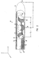
- FIG. 2 shows a detailed view of distal end 22 of catheter 20 in accordance with a preferred embodiment of the present invention.
- Device 28 comprises three non-concentric coils 60, 62 and 64, such as described in PCT patent publication number WO96/05768. This device enables continuous generation of six dimensions of position and orientation information with respect to an externally-applied magnetic field.
- Coils 60, 62 and 64 have respective axes 66, 68 and 70, which preferably define orthogonal Cartesian axes Z, X and Y. respectively, as shown in Fig. 2, wherein the Z-axis is parallel to the long axis of catheter 20 and the X- and Y-axes define a plane perpendicular thereto.
- the coils each have a fixed position and orientation with respect to each other.
- the inventive concepts of the present invention are similarly applicable to probes including other position sensing devices.
- the probe may comprise a single coil for generating position signals, or two or more such coils, which may be concentric or non-concentric.
- Other preferred embodiments of the present invention may comprise other types of position sensing devices known in the art, such as Hall effect devices or ultrasonic or optical sensors.
- device 28 is located in catheter 20 at a distance L from distal tip 26, where L is here defined for convenience as the distance along the Z-axis from the central axis 68 of coil 62 to tip 26.
- L is here defined for convenience as the distance along the Z-axis from the central axis 68 of coil 62 to tip 26.
- Respective axes 66 and 70 of coils 60 and 64 are displaced from axis 68 by respective distances d y and d z .
- coils 60, 62 and 64 When a time-varying external magnetic field is applied to distal end 22 of catheter 20, coils 60, 62 and 64 generate analog signals, which are preferably conveyed through the catheter by coil wires 72.
- the amplitudes of these analog signals are typically small relative to other electrical signals in and around catheter 20, such as the electrophysiological signals measured by functional portion 24 and conveyed through the catheter by functional wires 76.
- external magnetic fields may also cause undesired electrical currents, not generated by coils 60, 62 and 64, to flow in coil wires 72. These other electrical signals and undesired electrical currents can cause noise or interfering signals to appear together with the signals generated by the coils. Therefore, in preferred embodiments of the present invention, wires 72 are configured as twisted pairs and may also be shielded from electromagnetic interference by shields 74, so as to maintain a high signal-to-noise ratio in the position and orientation signals received from the coils.
- signal processing circuits 40 in console 34 receive the signals carried by coil wires 72 and convey them to computer 36, which computes the three-dimensional translational position of device 28 and the rotational orientation of axes 66, 68 and 70, relative to a fixed, external coordinate frame.
- the actual position and orientation of distal tip 26 are then computed by taking into account the distance L of tip 26 from the center of device 28, as defined by axis 68, and the orientation of axes 66, 68 and 70.
- the distance L typically varies from one catheter to another, leading to errors in calculating the position of tip 26.
- axis 66 of coil 60 typically deviates from absolute alignment with the long axis of catheter 20, which passes through tip 26, and axes 68 and 70 of coils 62 and 64 respectively are typically not precisely orthogonal to axis 66 or to each other, thereby inducing additional errors in determination of position and orientation of the catheter.
- variations in the respective gains of coils 60, 62 and 64 and in the distances d y and d z may cause additional errors in determination of position and orientation of the catheter.
- device 28 that is used to determine the position and orientation of catheter 20 is calibrated before the catheter is inserted into a patient's body.
- This calibration may be performed using any suitable method including the methods described in PCT/IL97/00060.
- the determined calibration correction function is thereafter stored electronically in a memory device, which device is preferably in catheter 20. When the catheter is coupled to console 34, this memory device is accessible to computer 36 in the console.
- Fig. 3 shows details of receptacle 33 and handle 30, in accordance with a preferred embodiment of the present invention.
- Handle 30 includes a digital microcircuit 90 in which calibration data for catheter 20 are electronically stored.
- Microcircuit 90 preferably includes an EEPROM or Flash ROM. but may alternatively include EPROM, PROM, non-volatile RAM, or other types of programmable memory devices known in the art.
- EEPROM Electrically erasable programmable read-only memory
- FIG. 3 shows details of receptacle 33 and handle 30, in accordance with a preferred embodiment of the present invention.
- Handle 30 includes a digital microcircuit 90 in which calibration data for catheter 20 are electronically stored.
- Microcircuit 90 preferably includes an EEPROM or Flash ROM. but may alternatively include EPROM, PROM, non-volatile RAM, or other types of programmable memory devices known in the art.
- microcircuit 88 is included in receptacle 33 of cable 21.
- Microcircuit 88 preferably includes a programmable memory similar to that of microcircuit 90.
- Information regarding initialization of catheter 20 which is common to all catheters of a certain model is preferably stored in microcircuit 88 rather than in microcircuit 90, which is embedded within the catheter itself.
- Most catheters are limited in the number of times they may be used, because of problems of cleaning, sterilization and wear. Commonly catheters may be used only once. Therefore, it is desirable to minimize the cost of the catheter itself by incorporating into catheter 20 only the minimal circuitry necessary, including a minimal size microcircuit 90.
- All other information which is characteristic commonly of all catheters of a given model is stored within receptacle 33, which is not inserted into the patient's body.
- information characteristic of a family of catheters is stored within console 36 while cable 21 only holds minimal information identifying which catheter model is being used.
- microcircuit 88 preferably stores calibration information relating to circuitry in the receptacle, as described below.
- handle 30 further includes pins 92, 94, 96 and 98, which mate with corresponding sockets 93 in receptacle 33.
- Functional pins 94 couple analog electrophysiological signals conveyed over functional wires 76 to signal processing circuits 40
- Coil pins 92 couple analog position and orientation signals conveyed by coil wires 72 from coils 60, 62 and 64 to signal processing circuits 40 and computer 36, which compute the position and orientation of catheter 20.
- the computer further reads the digital calibration correction data stored in microcircuit 90 via memory pins 96, and uses these data in computing the correct catheter position and orientation.
- Receptacle 33 preferably comprises one or more amplifiers 80 which amplify the position and orientation signals conveyed by coil wires 72. These signals are generally very weak, and therefore it is important to locate amplifiers 80 as close as possible to coils 60, 62, and 64 which produce the signals. However, it is advantageous not to locate amplifiers 80 within catheter 20 since they increase the cost and complexity of the catheter unduly.
- receptacle 33 further comprises one or more analog-to-digital (A/D) converters 82 which convert the analog signals from amplifiers 80 to digital form.
- A/D analog-to-digital
- the physiological signals conveyed over functional wires 76 are also amplified by amplifiers 84 and are then converted to digital form via A/D converter 86.
- calibration information for amplifiers 80 and 84 is stored in microcircuit 88.
- One or more write-enable pins 104 are preferably coupled to microcircuit 90. These pins are used to enable programming of the microcircuit with the desired calibration data. At the time of calibration, the write-enable input is enabled, and calibration data are recorded in the microcircuit. Thereafter the write-enable input is disabled, for example by removing the write-enable pin or by connecting it to electrical ground 106, as shown in Fig. 3, so that further calibration data may not be recorded in the microcircuit, and the microcircuit functions in a read-only mode. Microcircuit 88 may be programmed in like fashion.
- the write-enable input may be disabled by sending a write-protect command to the device. This command may be reversible or irreversible.
- microcircuit 90 comprises a device incorporating password-secured access control, and write-access to the microcircuit requires that an appropriate password first be entered.
- microcircuit 90 comprises a Password Access Security Supervisor (PASS TM ) X76F041 SecureFlash ROM device, manufactured by Xicor, Inc.
- PASS TM Password Access Security Supervisor
- the microcircuit is programmed with calibration data at the time of manufacture, and thereafter operates in a "read access only" mode, with all write operations locked out, or in a "read access and program only” mode, in which certain data, but not calibration data, may be written to the device, as will be described below. Changing the mode of operation of the microcircuit requires that an appropriate password be entered, which password is generally unavailable to users of the system.
- microcircuit 90 comprises an EPROM or PROM.
- Calibration data are recorded in the EPROM or PROM at the time of manufacture using a suitable programming device, not shown in the figures, which receives data from the computer used in calibration.
- the programming device is connected to handle 30 via a calibration socket, not shown in the figures, which like receptacle 33 is adapted to receive handle 30.
- the programming device programs the EPROM or PROM by inputting digital signals thereto through the connector. Thereafter, the EPROM or PROM may not be re-programmed.
- data recorded in microcircuit 90 and/or microcircuit 88 include a calibration code, which is encrypted in accordance with methods known in the art, so as to ensure that the calibration data have not been altered or corrupted.
- the calibration code includes a checksum.
- computer 36 reads the calibration code and compares the code with pre-programmed values. If the code does not match the desired pre-programmed value, the computer causes a message to be displayed by display 42 indicating that the catheter may not be appropriately calibrated. The computer may further cause the system to cease operation until a catheter having a code matching the desired pre-programmed value is connected thereto.
- the calibration code is encrypted using a method that prevents decryption by unauthorized parties, for example the RSA encryption scheme, using a public key and a private key, or other methods known in the art.
- a method such as RSA encryption
- the private key is known only to authorized manufacturers of the catheter, so as to prevent the possible use of unauthorized substitutes of possibly inferior quality.
- data recorded in microcircuit 90 include an expiration date and time, after which the catheter may not be used.
- Microcircuit 88 may similarly include data relating to the maximal period over which the catheter may be used.
- computer 36 reads the expiration date and time and compares them to the actual date and time, generated, for example, by a real-time clock circuit. If the expiration date and time have passed, the computer causes a message to be displayed by display 42 indicating that the catheter is unsuitable for further use. Alternatively or additionally, the computer may prevent usage of catheter 20 after the expiration date.
- cable 21 includes an internal clock which keeps track of the time and date.
- the internal clock of cable 21 keeps track of the relative time from the first use of catheter 20. Thus, it is not possible to avoid the usage prevention by changing the date in the console.
- the expiration date and time are recorded by computer 36 by programming microcircuit 90 when catheter 20 is first used.
- computer 36 detects that no expiration date and time have yet been recorded in microcircuit 90, and programs the microcircuit with the appropriate expiration date and time, at a pre-set interval after the current date and time.
- the pre-set interval is preferably determined by the manufacturer, based on the expected useful life of the catheter
- microcircuit 90 comprises a device including access control circuitry, such as the aforementioned X76F041 device
- the microcircuit is programmed so that a memory location therein is operable in a "read access and program only" mode.
- the mode may be changed only by entry of an appropriate password, which is generally not available to users of the system.
- a number stored in the memory location may be decreased, by changing a bit from "1" to "0", but not increased, since the microcircuit as programmed will not permit a "0" to be changed to a "1".
- the memory location is set at the time of manufacture to contain a maximum value, i.e., all bits set to "1".
- computer 36 programs the microcircuit with the appropriate expiration time and date by changing one or more bits in the memory location from "1" to "0". Thereafter, the expiration date cannot be changed to any later date (unless the correct password is first entered).
- microcircuit 90 comprising access control circuitry, as described above, may be used to track the number of times catheter 20 has been used, in a manner that is protected from possible tampering or error by a user thereof.
- a record corresponding to the number of times catheter 20 may be used is stored in a memory location in the device at the time of manufacture, and the microcircuit is programmed so that this memory location is operable in the "read access and program only" mode, as described above.
- computer 36 reads the record in the memory location and reduces it by changing one or more bits therein from "1" to "0".
- the computer When all the bits in the record are equal to zero, or the record reaches some other predetermined minimum value, the computer causes a message to be displayed to the user indicating that the catheter is unsuitable for further use and, preferably, prevents further operation until a suitable catheter is connected thereto.
- microcircuit 90 may be used to track the duration of use of catheter 20.
- a record corresponding to the duration of use of the catheter is stored in a "read access and program only" memory location in the microcircuit.
- computer 36 While the catheter is in use, at regular, predetermined intervals, computer 36 reads the record and reduces it by changing one or more bits therein from "1" to "0". When the entire record reaches zero, or some other minimum value, further operation is prevented, as described above.
- the low-level analog signals conveyed from coils 60, 62 and 64 over coil wires 72 must generally be protected from interference due to other analog signals in functional wires 76 and digital signals conveyed to an from microcircuit 90. Therefore, in preferred embodiments of the present invention, as shown in Fig. 3, handle 30 includes electromagnetic shields 74, which are coupled to ground via pin 98 on the connector.
- shields 74 are active shields, which are driven by noise canceling circuitry (not shown).
- calibration data stored in catheter 20, and specifically in microcircuits 88 and 90 may relate to other aspects of the catheter.
- calibration data relating to a physiological sensor, actuator or therapeutic tool are stored in the catheter.
- calibration data may be stored in the catheter regarding the gain of a piezoelectric motion control device used in steering the catheter's distal end.
Description
- This application is related to PCT patent application PCT/IL97/00060.
- The present invention relates generally to systems for medical diagnosis and treatment, and specifically to medical catheters whose location can be detected.
- Various methods and devices have been described for determining the position of a probe or catheter tip inside the body using electromagnetic fields, such as in U.S. patent 5,042,486 and PCT
patent publication WO 94/04938. Other electromagnetic tracking systems, not necessarily for medical applications, are described in U.S. patents 3,644,825, 3,868,565, 4, 017,858, 4,054,881 and 4,849,692. - U.S. patent 5,391,199, describes a system that incorporates a catheter, which includes a position measuring device that can determine the position of the catheter in three dimensions, but not its orientation.
- PCT patent application PCT/WO96/0576S. which is assigned to the assignee of the present patent application, describes a catheter system including means for determining the six-dimensions of position and orientation of the catheter's distal tip. This system uses a position sensor, formed of a plurality of non-concentric coils, adjacent to a locatable site in the catheter, for example near its distal tip. Preferably three orthogonal coils are used. These coils generate signals in response to externally applied magnetic fields, which allow for the computation of six position and orientation coordinates, so that the position and orientation of the catheter are known without the need for imaging the catheter.
- U.S. patent 4,580,557 describes a surgical laser system for connection to various peripheral surgical devices. The system identifies to which device it is connected according to characteristics of a signature resistor embedded within the device. The resistor uniquely identifies the device in which it is embedded.
- U.S. patent 5.383.874 describes a system for identifying and monitoring catheters, including identification means carried within the handle of the catheter body. In one embodiment of the catheter in this patent, the handle includes a solid-state microchip pre-programmed with a digital value representing an identification code and other operational and functional characteristics of the catheter. The handle is connected by a cable to a control console, which receives data from the microchip. In one disclosed embodiment, the microchip may record the number of times the catheter has been used.
- U.S. patent 5,617,857 describes an imaging system which determines the location of a medical instrument. A read-only storage device is positioned on or in the medical instrument for storing initialization information characteristic of the instrument. Thus, the system may determine the type of the instrument connected thereto, and receive initialization information associated with the instrument type. This patent further suggests preventing use of the instrument unless the initialization information was transferred from the storage device to the imaging system. A verification method is also described in which the initialization information is verified for correctness. Two alternatives are suggested for the location of the storage device. One alternative suggests embedding the device directly in the instrument. A second alternative suggests embedding the storage device within an attachment, essentially an instrument handle, to which a certain type of instrument may be fit.
- Thus, in some of the embodiments described in the above-referenced patents, information regarding a catheter (or other medical tool) is stored in an attachment to the catheter and not in the catheter itself These embodiments are not suitable for storing item-specific information such as calibration information.
- In other embodiments of the above-referenced patents, information is stored in the catheter. These embodiments, however, suffer from over-complexity, requiring for example multiple digital signal wires to run along the catheter. This complexity is not feasible for mass use in disposable catheters.
- WO-A 97/29678, there is disclosed a probe assembly of the type set forth in the preamble of the accompanying claim 1.
- US-A-5400267 discloses a reusable connecting cable wich may be used interchangeably with a number of compatible instruments.
- It is an object of some aspects of the present invention to provide means for convenient electronic storage and recall of calibration information regarding a probe such as a catheter.
- It is another object of some aspects of the present invention to provide means for convenient electronic storage and recall of calibration information regarding a probe, in which the recall time of the information is minimal.
- It is another object of some aspects of the present invention to provide means for providing improved communication between the probe and a control console.
- It is a further object of some aspects of the present invention to provide probes of minimal cost and complexity, which are capable of storing and recalling calibration information.
- In one aspect of the present invention, a probe assembly for connection to a control console comprises two parts: a catheter of minimal complexity which is inserted into a patient's body, and a connection cable which connects between the proximal end of the catheter and the console. The catheter comprises a microcircuit which carries substantially only information specific to the catheter, which is not in common with other catheters of the same model. Such information includes, for example, item-specific calibration data and a date of first use of the catheter. The cable comprises an access circuit which receives the information from the catheter and passes it in a suitable form to the console.
- Preferably, the cable operates with all catheters of a specific model or type, and therefore when a catheter is replaced, there is no need to replace the cable. Particularly, catheters which are planned for one-time use do not require replacement of the cable, which does not come in contact with patients.
- In a preferred embodiment of the present invention, the access circuit verifies that the catheter is of the model which is compatible with the cable. Preferably, the connection between the catheter and the cable is unique for each catheter model. Alternatively or additionally, the model identification is stored in the microcircuit and the access circuit verifies that the model identification is the same in the cable and the catheter.
- In some preferred embodiments of the present invention, each cable is associated with a few catheter models, and the model identification stored in the microcircuit is used by the access circuitry to identify which catheter model is in use.
- In some preferred embodiments of the present invention, the catheter microcircuit contains data which is stored digitally. Preferably, the leads of the microcircuit are coupled directly to sockets in a receptacle at the distal end of the cable. Thus, the catheter does not contain digital signal wires, and still allows quick access to the information in the microcircuit. Also, digital electronic signals transmitted from the microcircuit to the console via the cable do not interfere with low-level analog signals conveyed by wires from the distal end of the catheter to the cable. Preferably, the access circuit is located within the receptacle at the distal end of the cable and includes the socket which receives the leads of the microcircuit.
- In preferred embodiments of the present invention, the microcircuit stores minimal calibration and/or initialization information regarding the catheter. Alternatively or additionally, the microcircuit stores usage information regarding the catheter, such as the date of first use of the catheter.
- In preferred embodiments of the present invention, the catheter comprises at its proximal end a handle which contains controls which are used to manipulate the catheter. It is noted that in catheters in which the handle is not at the proximal end of the catheter, the length beyond the handle does not add to the functionality of the catheter but raises the cost of the catheter and of sterilization thereof. Preferably, the catheter microcircuit is contained in the handle. Alternatively, the handle is separate from the catheter, and is rather fixed at the distal end of the cable, and the microcircuit is contained within a connector at the proximal end of the catheter, which connects to the handle.
- In some preferred embodiments of the present invention, the catheter includes coils which generate analog signals indicative of the position of the catheter, as described, for example, in the above-reference PCT/WO96/05768 patent application. The cable preferably comprises amplifiers which are used to amplify the analog signals. Alternatively or additionally, the amplifiers may be used to amplify other signals, such as physiological measurements. Preferably, the amplifiers are within the receptacle so that they are as close as possible to the coils and/or the other sources of signals. It is noted that placing the amplifiers within the console is not desirable due to interference from circuitry of the console which generates noise in neighboring wires and due to noise pickup over the long distance between the distal end of the catheter and the console. The signals generated within the catheter are relatively weak and must be protected from attenuation and noise. Placing the amplifiers in the catheter adds to the complexity and cost of the catheter, which is also undesirable.
- In some of these preferred embodiments, the access circuitry includes one or more analog-to-digital (A/D) converter circuits, which convert analog signals from the catheter into a digital form, which is conveyed to the console. Thus, the attenuation and noise problems mentioned above are substantially eliminated.
- In other preferred embodiments of the present invention, the catheter itself includes the one or more analog-to-digital (A/D) converter circuits. In these embodiments, the access circuit couples only digital signals from the catheter to the console. In one such preferred embodiment, an A/D converter is adjacent to the distal tip of the catheter.
- In some preferred embodiments of the present invention, the cable comprises an additional microcircuit in which information characteristic of the one or more models of catheters associated with the cable, is stored. Such information may include, for example, the configuration of the catheters and usage codes. Preferably, the additional microcircuit also includes calibration information for the access circuit and the amplifiers within the cable. The calibration information of the amplifiers may include, for example, their zero-gain, DC offset and linearity. Thus, information which does not have to be in the catheter is stored in the cable, and the catheter is less complex and costly. Preferably, the console substantially does not require any other catheter-specific information beyond that supplied by the microcircuits in the catheter and, preferably, the cable, so that newer models of catheters may be used with the console without updating software or hardware of the console.
- Preferably, the microcircuits comprise a read/write memory component, such as an EEPROM, EPROM, PROM, Flash ROM or non-volatile RAM, and the information is stored in digital form. Alternatively or additionally, either of the microcircuits may comprise a read-only memory which is pre-programmed at the time of manufacture.
- In preferred embodiments of the present invention, the calibration information includes data relating to the relative displacement of the distal tip of the catheter from the coils. In some other preferred embodiments of the present invention, the calibration information also includes data relating to deviation of the coils from orthogonality, or data relating to the respective gains of the coils, or a combination of these data. The above calibration information generally varies from one catheter to the other and therefore is preferably stored in the microcircuit within the catheter. Preferably, the data is determined in a calibration method, such as described in PCT/IL97/00060. Other calibration information may include the general configuration of the catheter and the gain and offset of the access circuitry, and is preferably stored in the microcircuit in the cable.
- In some preferred embodiments of the present invention, the catheter is electrically isolated from signal processing and computing apparatus in the console, and the calibration information includes data relating to isolation circuitry in the catheter. Preferably, the catheter is isolated by at least one inductive element, such as an isolation transformer, adjacent to the proximal end of the catheter or in the catheter handle. Alternatively, the catheter may be isolated by one or more opto-isolators, or other types of isolation circuitry known in the art. Such inductive elements and other isolation circuitry typically introduce non-linearities in signals conveyed thereby. Such non-linearities may lead to significant distortions particularly in analog signals conveyed by wires from the distal end of the catheter to the signal processing circuits. Therefore, the calibration information preferably includes data relating to signal non-linearities introduced by the inductive elements and/or other isolation circuitry.
- The calibration data may be recorded in the microcircuit in the catheter in the form of lookup tables, polynomial coefficients or any other suitable form known in the art.
- In preferred embodiments of the present invention, calibration data are produced and recorded at or close to the time of manufacture, and the microcircuits are configured so as to prevent subsequent recording of calibration data by a user. For example, when the microcircuit comprises an EPROM or PROM, a suitable programming device connects to the catheter connector and programs the EPROM or PROM by inputting digital signals thereto through the connector from a computer used in calibration. Thereafter, the EPROM or PROM may not be re-programmed.
- In other such preferred embodiments wherein the microcircuit comprises an EEPROM or non-volatile RAM device, the EEPROM or non-volatile RAM device includes a write-enable input connection, of a type known in the art, which is connected to a write-enable pin in the connector at the proximal end of the catheter. At the time of calibration, the write-enable input is enabled, and calibration data are recorded in the microcircuit. Thereafter the write-enable input is disabled, for example by removing the write-enable pin or by connecting it to electrical ground, so that further calibration data may not be recorded in the microcircuit.
- Alternatively, in preferred embodiments of the present invention wherein the microcircuit comprises an EEPROM device, the write-enable input may be disabled by sending a write-protect command to the device. This command may be reversible or irreversible.
- In still other preferred embodiments of the present invention, the microcircuit in the catheter and/or the microcircuit in the cable comprise access control circuitry, such as, for example, the X76F041 Password Access Security Supervisor (PASSTM) SecureFlash ROM device, manufactured by Xicor, Inc. The microcircuit is preferably programmed with a password, so that after calibration data are produced and recorded at the time of manufacture, further calibration data may not be recorded in the microcircuit, with the possible exception of data recording by factory-authorized personnel to whom the password is known.
- In some preferred embodiments of the present invention, data recorded in the microcircuit include a calibration code, which is encrypted in accordance with methods known in the art, so as to ensure that calibration data have not been altered or corrupted. When a user connects the catheter to a suitable console, which console comprises a computer, the computer reads the calibration code and compares the code with pre-programmed values. If the code does not match the desired pre-programmed value, the computer causes a message to be displayed indicating that the catheter may not be appropriately calibrated. The computer may prevent further operation until a catheter having a code matching the desired pre-programmed value is connected thereto.
- Preferably the calibration code is encrypted using a method that prevents decryption by unauthorized parties, for example the RSA encryption scheme, using a public key and a private key, or other methods known in the art. When a method such as RSA encryption is used, the private key is known only to authorized manufacturers of the catheter, so as to prevent the possible use of unauthorized substitutes of possibly inferior quality.
- In further preferred embodiments of the present invention, data recorded in the microcircuit include an expiration date and time, after which the catheter may not be used. When a user connects the catheter to a suitable console, which console comprises a computer, the computer reads the expiration date and time and compares them to the actual date and time, generated, for example, by a real-time clock circuit. If the expiration date and time have passed, the computer causes a message to be displayed indicating that the catheter is unsuitable for further use. The computer may prevent further operation until a catheter having a valid expiration date and time is connected thereto.
- Preferably the expiration date and time are recorded by the console computer by programming the microcircuit in the catheter when the catheter is first used. Thus, when the catheter is connected to a console for the first time, the computer detects that no expiration date and time have yet been recorded in the microcircuit, and programs the microcircuit with the appropriate expiration data and time, at a pre-set interval after the actual date and time. Preferably, the pre-set interval is stored within the cable and is determined by the manufacturer, based on the expected useful life of the catheter.
- In a preferred embodiment in which the microcircuit comprises access control circuitry, the microcircuit is programmed so that a memory location therein is operable in a "read access and program only" mode. The mode may be changed only by entry of an appropriate password, which is generally not available to users of the catheter. In the "read access and program only" mode, a number stored in the memory location may be decreased, by changing a bit from "1" to "0", but not increased, since the microcircuit as programmed will not permit a "0" to be changed to a "1". Preferably the memory location is set at the time of manufacture to contain maximum value, i.e., all bits set to "1". Then, as described above, at the time of first use, the computer programs the microcircuit with the microcircuit with the appropirate expiration time and date by changing one or more bits in the memory location from "1" to "0". Thereafter, the expiration date cannot be changed to any later date (unless the correct password is first entered).
- Alternatively or additionally, the microcircuit comprising access control circuitry, as described above, may be used to track the number of times the catheter has been used and/or the duration of use, in a manner that is protected from possible tampering or error by a user thereof. Preferably, a record corresponding to the number of times and/or the length of time that the catheter may be used is stored in a memory location in the device or in the microcircuit within the catheter, at the time of manufacture, and the microcircuit is programmed so that this memory location is operable in the "read access and program only" mode, as described above. Each time the catheter is used, and/or at regular time intervals during use, the computer reads the record in the memory location and reduces it by changing one or more bits therein from "1" to "0". When the record stored in the memory location reaches zero, or some other predetermined minimum value, the computer causes a message to be displayed to the user indicating that the catheter is unsuitable for further use and, preferably, prevents further operation until a suitable catheter is connected thereto.
- There is therefore provided in accordance with the present invention, a probe assembly for connection to a console including a probe for insertion into the body of a subject, said probe having distal and proximal ends and a microcircuit which stores information relating to the probe and a cable for connecting the probe to the console, said cable including access circuitry for accessing the microcircuit in the probe, the information relating to the probe including usage-related information for controlling availability of the probe to a user thereof, characterized in that
the cable is interchangeably connectable to two or more different probes of a common type, and the microcircuit stores information relating uniquely to the probe and substantially not in common with other probes of the type. - The access circuitry includes a cable-microcircuit, which stores information relating commonly to different probes of the common type such as information identifying the type of the probe.
- Preferably, the usage related information includes a usage code, and the access circuitry allows the usage code to be changed so as to reduce the availability of the probe, but not to increase the availability thereof
- Preferably, the microcircuit stores the usage code in a memory location therein that is controlled by the access circuitry so as to operate in a read access and program only mode, and the mode may be changed by entry of a password to the access circuitry.
- Alternatively or additionally, the usage code includes date information.
- Preferably, the microcircuit is adjacent to the proximal end of the probe.
- Preferably, the microconduit includes leads which protrude from the proximal end of the probe and wherein the access circuitry includes a socket which receives the leads of the microcircuit
- Preferably, the probe includes a functional portion which generates analog signals and wherein the access circuitry includes one or more amplifiers which amplify the analog signals.
- Preferably, the access circuitry includes one or more analog to digital converters.
- Preferably, the access circuitry includes a cable-microconduit, which stores information relating to calibration of the one or more amplifiers.
- Alternatively or additionally, the access circuitry includes a cable-microcircuit which stores information relating to the probe assembly.
- Preferably, the cable-microcircuit stores information descriptive of a configuration of the probe, or an allowed usage period for the probe.
- Alternatively or additionally, the cable includes an internal clock for measuring the time from a first usage of the catheter.
- Preferably, at least a portion of the information on the microcircuit is encrypted.
- Preferably, the information relating to the probe includes calibration information of the probe.
- Preferably, the probe includes a device that generates signals responsive to the position or orientation of the probe, and the calibration information of the probe includes information relating to calibration of the signal generating device.
- Preferably, the signal generating device is adjacent to the distal end of the probe.
- Further preferably, the signal generating device includes one or more coil, and preferably, wherein the calibration information includes information relating to a gain of at least one of the one or more coils, or an angular orientation of at least one of the one or more coils.
- Alternatively or additionally, the calibration information includes information relating to a positional displacement of the signal generating device, relative to the distal end of the probe.
- Preferably, the probe includes isolation circuitry, and wherein the information relating to the probe includes information relating to a non-linearity of the isolation circuitry.
- Preferably, the microcircuit includes a programmable memory device, an EEPROM device, an EPROM or PROM device, a non-volatile RAM device or a Flash ROM device.
- Preferably, the cable includes means for disabling at least one of the connections for programming the programmable memory device.
- Preferably, the probe assembly further includes a console, including a computer, which is adapted to receive said information and determine therefrom the position of the probe.
- Preferably, the probe includes a device that generates signals responsive to the position or orientation of the probe, and the calibration information of the probe includes information relating to calibration of the signal generating device.
- Preferably, the computer is adapted to program the programmable memory device.
- There is further provided in accordance with a preferred embodiment of the present invention, a method of initializing a console for use with a probe assembly as claimed in claim 1 including a probe and a connection cable, including connecting the probe to the console using the cable, loading the console with general model information from a microcircuit within the cable, and loading the console with specific catheter information from a microcircuit within the catheter.
- Preferably, the specific catheter information includes calibration information, a usage code and/or a first usage date.
- Preferably, the general model information includes a permitted usage duration, and the method preferably includes displaying a warning message if the usage duration from the first usage date has expired.
- Preferably, connecting the probe to the console includes connecting the probe via access circuitry in the cable.
- Preferably, the method includes loading the console with calibration information regarding the access circuitry.
- The present invention will be more fully understood from the following detailed description of the preferred embodiments thereof, taken together with the drawings in which:
-
- Fig. 1 is a perspective view of a system including a catheter and a connection cable, in accordance with a preferred embodiment of the present invention;
- Fig. 2 is a detailed sectional view of the distal end of the catheter of Fig. 1 ; and
- Fig. 3 is a detailed schematic view of a connection site between the catheter and the cable, in accordance with a preferred embodiment of the present invention.
- Fig. 1 shows a
probe system 18 in accordance with a preferred embodiment of the present invention.System 18 comprises an elongate probe, preferably acatheter 20, for insertion into the human body. It will be understood that although the following preferred embodiments are described with reference to a catheter, the present invention is equally applicable to other types of probes. - A
distal end 22 ofcatheter 20 includes afunctional portion 24 for performing diagnostic and/or therapeutic functions, adjacent todistal tip 26.Functional portion 24 may, for example, comprise electrodes (not shown in the figure) for performing electrophysiological measurements or for electrosurgical ablation of areas of pathology in the heart. Alternatively or additionally, the functional portion may comprise other types of sensors, or optical or ultrasound imaging devices. -
Distal end 22 ofcatheter 20 further includes adevice 28 that generates signals used to determine the position and orientation of the catheter within the body.Device 28 is preferably adjacent tofunctional portion 24. There is preferably a fixed positional and orientational relationship betweendevice 28,tip 26 andportion 24. -
Catheter 20 preferably includes ahandle 30, which includescontrols 32 which are used by a surgeon to steer the distal end of the catheter in a desired direction, or to position and/or orient it as desired. - The system shown in Fig. 1 further comprises a
console 34, which enables the user to observe and regulate the functions ofcatheter 20.Console 34 preferably includes acomputer 36, keyboard 38,signal processing circuits 40, which are typically inside the computer, anddisplay 42.Signal processing circuits 40 typically receive, amplify, filter and digitize signals fromcatheter 20, including signals generated by positionsignal generating device 28, whereupon these digitized signals are received and used bycomputer 36 to compute the position and orientation of the catheter. Alternatively, appropriate circuitry may be associated with the catheter itself, as described below, so thatcircuits 40 receive signals that are already amplified, filtered and/or digitized. -
Catheter 20 is coupled tocomputer 36 via anextension cable 21, which at its proximal end comprises aconnector 44 adapted to fit in amating receptacle 46 onconsole 34. The distal end ofcable 21 comprises areceptacle 33 which connects to handle 30.Receptacle 33 is preferably configured to receive catheters of a specific model, and preferably includes user-tangible identification of the specific model. One of the advantages in usingcable 21 is the ability to connect different models and types of catheters, possibly having different handle configurations, to thesame console 34.Different cables 21 can be used to connect a large variety of catheters to console 34. Another advantage in having aseparate cable 21 is in the fact that the cable does not come into contact with patients and therefore it is possible to re-use the cable without sterilization. - Preferably,
cable 21 further contains one or more isolation transformers (not shown in the figures), which electrically isolatecatheter 20 fromconsole 34. The isolation transformers are preferably contained inreceptacle 33. - Reference is now made to Fig. 2, which shows a detailed view of
distal end 22 ofcatheter 20 in accordance with a preferred embodiment of the present invention.Device 28 comprises threenon-concentric coils Coils respective axes catheter 20 and the X- and Y-axes define a plane perpendicular thereto. The coils each have a fixed position and orientation with respect to each other. - Although preferred embodiments of the present invention are described herein with reference to position
signal generating device 28 shown in Fig. 2 and described above, it will be understood that the inventive concepts of the present invention are similarly applicable to probes including other position sensing devices. For example, in other preferred embodiments of the present invention, the probe may comprise a single coil for generating position signals, or two or more such coils, which may be concentric or non-concentric. Other preferred embodiments of the present invention may comprise other types of position sensing devices known in the art, such as Hall effect devices or ultrasonic or optical sensors. - As shown in Fin. 2,
device 28 is located incatheter 20 at a distance L fromdistal tip 26, where L is here defined for convenience as the distance along the Z-axis from thecentral axis 68 ofcoil 62 to tip 26.Respective axes coils axis 68 by respective distances dy and dz. - When a time-varying external magnetic field is applied to
distal end 22 ofcatheter 20, coils 60, 62 and 64 generate analog signals, which are preferably conveyed through the catheter bycoil wires 72. The amplitudes of these analog signals are typically small relative to other electrical signals in and aroundcatheter 20, such as the electrophysiological signals measured byfunctional portion 24 and conveyed through the catheter byfunctional wires 76. Furthermore, external magnetic fields may also cause undesired electrical currents, not generated bycoils coil wires 72. These other electrical signals and undesired electrical currents can cause noise or interfering signals to appear together with the signals generated by the coils. Therefore, in preferred embodiments of the present invention,wires 72 are configured as twisted pairs and may also be shielded from electromagnetic interference byshields 74, so as to maintain a high signal-to-noise ratio in the position and orientation signals received from the coils. - As described in the above-mentioned 05768 PCT patent publication,
signal processing circuits 40 inconsole 34 receive the signals carried bycoil wires 72 and convey them tocomputer 36, which computes the three-dimensional translational position ofdevice 28 and the rotational orientation ofaxes distal tip 26 are then computed by taking into account the distance L oftip 26 from the center ofdevice 28, as defined byaxis 68, and the orientation ofaxes - It has been found empirically that due to deviations in the process of
manufacturing catheter 20, the distance L typically varies from one catheter to another, leading to errors in calculating the position oftip 26. Furthermore,axis 66 ofcoil 60 typically deviates from absolute alignment with the long axis ofcatheter 20, which passes throughtip 26, and axes 68 and 70 ofcoils axis 66 or to each other, thereby inducing additional errors in determination of position and orientation of the catheter. Finally, variations in the respective gains ofcoils - Therefore, in preferred embodiments of the present invention,
device 28 that is used to determine the position and orientation ofcatheter 20 is calibrated before the catheter is inserted into a patient's body. This calibration may be performed using any suitable method including the methods described in PCT/IL97/00060. The determined calibration correction function is thereafter stored electronically in a memory device, which device is preferably incatheter 20. When the catheter is coupled to console 34, this memory device is accessible tocomputer 36 in the console. - Fig. 3 shows details of
receptacle 33 and handle 30, in accordance with a preferred embodiment of the present invention.Handle 30 includes adigital microcircuit 90 in which calibration data forcatheter 20 are electronically stored.Microcircuit 90 preferably includes an EEPROM or Flash ROM. but may alternatively include EPROM, PROM, non-volatile RAM, or other types of programmable memory devices known in the art. When acatheter 20 is calibrated, its specific calibration data are stored inmicrocircuit 90 and thus the data is conveniently accessible tocomputer 36, as will be described below. - Preferably, another
microcircuit 88 is included inreceptacle 33 ofcable 21.Microcircuit 88 preferably includes a programmable memory similar to that ofmicrocircuit 90. Information regarding initialization ofcatheter 20 which is common to all catheters of a certain model is preferably stored inmicrocircuit 88 rather than inmicrocircuit 90, which is embedded within the catheter itself Most catheters are limited in the number of times they may be used, because of problems of cleaning, sterilization and wear. Commonly catheters may be used only once. Therefore, it is desirable to minimize the cost of the catheter itself by incorporating intocatheter 20 only the minimal circuitry necessary, including aminimal size microcircuit 90. All other information which is characteristic commonly of all catheters of a given model is stored withinreceptacle 33, which is not inserted into the patient's body. Alternatively or additionally, information characteristic of a family of catheters is stored withinconsole 36 whilecable 21 only holds minimal information identifying which catheter model is being used. - An advantage of having the model information in
receptacle 33 rather than inconsole 36 lies in allowing use of a large variety of catheters withconsole 36 without loading large databases into the console. Furthermore,microcircuit 88 preferably stores calibration information relating to circuitry in the receptacle, as described below. These features allow using a standard console with various catheter types, rather than having asingle console 36 associated with each type of catheter. Furthermore, newer models of catheters may be used withconsole 36 simply by connecting them via theircompatible cable 21 to the console, thus reducing the need to update software in the console or to acquire a new console. - In the preferred embodiment shown in Fig. 3, handle 30 further includes
pins corresponding sockets 93 inreceptacle 33.Functional pins 94 couple analog electrophysiological signals conveyed overfunctional wires 76 to signalprocessing circuits 40 Coil pins 92 couple analog position and orientation signals conveyed bycoil wires 72 fromcoils processing circuits 40 andcomputer 36, which compute the position and orientation ofcatheter 20. The computer further reads the digital calibration correction data stored inmicrocircuit 90 via memory pins 96, and uses these data in computing the correct catheter position and orientation. -
Receptacle 33 preferably comprises one ormore amplifiers 80 which amplify the position and orientation signals conveyed bycoil wires 72. These signals are generally very weak, and therefore it is important to locateamplifiers 80 as close as possible tocoils amplifiers 80 withincatheter 20 since they increase the cost and complexity of the catheter unduly. Preferably,receptacle 33 further comprises one or more analog-to-digital (A/D)converters 82 which convert the analog signals fromamplifiers 80 to digital form. - Preferably, the physiological signals conveyed over
functional wires 76 are also amplified byamplifiers 84 and are then converted to digital form via A/D converter 86. Preferably, calibration information foramplifiers microcircuit 88. - One or more write-enable
pins 104 are preferably coupled tomicrocircuit 90. These pins are used to enable programming of the microcircuit with the desired calibration data. At the time of calibration, the write-enable input is enabled, and calibration data are recorded in the microcircuit. Thereafter the write-enable input is disabled, for example by removing the write-enable pin or by connecting it toelectrical ground 106, as shown in Fig. 3, so that further calibration data may not be recorded in the microcircuit, and the microcircuit functions in a read-only mode.Microcircuit 88 may be programmed in like fashion. - Alternatively, in preferred embodiments of the present invention wherein
microcircuit 90 comprises an EEPROM device, the write-enable input may be disabled by sending a write-protect command to the device. This command may be reversible or irreversible. - In other preferred embodiments of the present invention,
microcircuit 90 comprises a device incorporating password-secured access control, and write-access to the microcircuit requires that an appropriate password first be entered. For example, in one such preferred embodiment,microcircuit 90 comprises a Password Access Security Supervisor (PASSTM) X76F041 SecureFlash ROM device, manufactured by Xicor, Inc. The microcircuit is programmed with calibration data at the time of manufacture, and thereafter operates in a "read access only" mode, with all write operations locked out, or in a "read access and program only" mode, in which certain data, but not calibration data, may be written to the device, as will be described below. Changing the mode of operation of the microcircuit requires that an appropriate password be entered, which password is generally unavailable to users of the system. - In another preferred embodiment of the present invention,
microcircuit 90 comprises an EPROM or PROM. Calibration data are recorded in the EPROM or PROM at the time of manufacture using a suitable programming device, not shown in the figures, which receives data from the computer used in calibration. The programming device is connected to handle 30 via a calibration socket, not shown in the figures, which likereceptacle 33 is adapted to receivehandle 30. The programming device programs the EPROM or PROM by inputting digital signals thereto through the connector. Thereafter, the EPROM or PROM may not be re-programmed. - In some preferred embodiments of the present invention, data recorded in
microcircuit 90 and/ormicrocircuit 88 include a calibration code, which is encrypted in accordance with methods known in the art, so as to ensure that the calibration data have not been altered or corrupted. Preferably the calibration code includes a checksum. When the user connectscatheter 20 to console 34,computer 36 reads the calibration code and compares the code with pre-programmed values. If the code does not match the desired pre-programmed value, the computer causes a message to be displayed bydisplay 42 indicating that the catheter may not be appropriately calibrated. The computer may further cause the system to cease operation until a catheter having a code matching the desired pre-programmed value is connected thereto. - Preferably the calibration code is encrypted using a method that prevents decryption by unauthorized parties, for example the RSA encryption scheme, using a public key and a private key, or other methods known in the art. When a method such as RSA encryption is used, the private key is known only to authorized manufacturers of the catheter, so as to prevent the possible use of unauthorized substitutes of possibly inferior quality.
- In further preferred embodiments of the present invention, data recorded in
microcircuit 90 include an expiration date and time, after which the catheter may not be used.Microcircuit 88 may similarly include data relating to the maximal period over which the catheter may be used. When a user connectscatheter 20 to aconsole 34,computer 36 reads the expiration date and time and compares them to the actual date and time, generated, for example, by a real-time clock circuit. If the expiration date and time have passed, the computer causes a message to be displayed bydisplay 42 indicating that the catheter is unsuitable for further use. Alternatively or additionally, the computer may prevent usage ofcatheter 20 after the expiration date. - In a preferred embodiment of the present invention,
cable 21 includes an internal clock which keeps track of the time and date. Alternatively or additionally, the internal clock ofcable 21 keeps track of the relative time from the first use ofcatheter 20. Thus, it is not possible to avoid the usage prevention by changing the date in the console. - Preferably the expiration date and time are recorded by
computer 36 by programmingmicrocircuit 90 whencatheter 20 is first used. Whencatheter 20 is connected to console 34 for the first time,computer 36 detects that no expiration date and time have yet been recorded inmicrocircuit 90, and programs the microcircuit with the appropriate expiration date and time, at a pre-set interval after the current date and time. The pre-set interval is preferably determined by the manufacturer, based on the expected useful life of the catheter - In preferred embodiments of the present invention in which microcircuit 90 comprises a device including access control circuitry, such as the aforementioned X76F041 device, the microcircuit is programmed so that a memory location therein is operable in a "read access and program only" mode. The mode may be changed only by entry of an appropriate password, which is generally not available to users of the system. In the "read access and program only" mode, a number stored in the memory location may be decreased, by changing a bit from "1" to "0", but not increased, since the microcircuit as programmed will not permit a "0" to be changed to a "1". Preferably the memory location is set at the time of manufacture to contain a maximum value, i.e., all bits set to "1". Then, as described above, at the
time catheter 20 is first used,computer 36 programs the microcircuit with the appropriate expiration time and date by changing one or more bits in the memory location from "1" to "0". Thereafter, the expiration date cannot be changed to any later date (unless the correct password is first entered). - Alternatively or additionally,
microcircuit 90 comprising access control circuitry, as described above, may be used to track the number oftimes catheter 20 has been used, in a manner that is protected from possible tampering or error by a user thereof. Preferably, a record corresponding to the number oftimes catheter 20 may be used is stored in a memory location in the device at the time of manufacture, and the microcircuit is programmed so that this memory location is operable in the "read access and program only" mode, as described above. Each time the catheter is used,computer 36 reads the record in the memory location and reduces it by changing one or more bits therein from "1" to "0". When all the bits in the record are equal to zero, or the record reaches some other predetermined minimum value, the computer causes a message to be displayed to the user indicating that the catheter is unsuitable for further use and, preferably, prevents further operation until a suitable catheter is connected thereto. - Similarly, either alternatively or additionally,
microcircuit 90 may be used to track the duration of use ofcatheter 20. In this case, a record corresponding to the duration of use of the catheter is stored in a "read access and program only" memory location in the microcircuit. While the catheter is in use, at regular, predetermined intervals,computer 36 reads the record and reduces it by changing one or more bits therein from "1" to "0". When the entire record reaches zero, or some other minimum value, further operation is prevented, as described above. As noted earlier, the low-level analog signals conveyed fromcoils coil wires 72 must generally be protected from interference due to other analog signals infunctional wires 76 and digital signals conveyed to an frommicrocircuit 90. Therefore, in preferred embodiments of the present invention, as shown in Fig. 3, handle 30 includeselectromagnetic shields 74, which are coupled to ground viapin 98 on the connector. - In another preferred embodiment of the present invention, shields 74 are active shields, which are driven by noise canceling circuitry (not shown).
- Although most of the features and capabilities of
system 18, particularly features related to access control, have been described above with reference tomicrocircuit 90 incatheter handle 30, it will be clear to those skilled in the art that many of these features and capabilities could be implemented usingmicrocircuit 88 incable 21, as well. - Furthermore, although the above preferred embodiments have been described with reference to calibration of position and orientation sensing apparatus, in other preferred embodiments of the present invention, calibration data stored in
catheter 20, and specifically inmicrocircuits - It will be appreciated that the preferred embodiments of the invention described above are cited by way of example, and the full scope of the invention is limited only by the claims which follow.
Claims (28)
- A medical probe assembly (18) for connection to a console (34) comprising:a probe (20) for insertion into the body of a subject, said probe having distal and proximal ends and comprising a microcircuit (90) which stores information relating to the probe; anda cable (21) for connecting the probe (20) to the console (34), said cable comprising access circuitry for accessing the microcircuit (90) in the probe,the information relating to the probe comprising usage-related information for controlling availability of the probe to a user thereof, characterised in thatthe cable (21) is interchangeably connectable to two or more different probes (20) of a common type, and the microcircuit (90) stores information relating uniquely to the probe (20) and substantially not in common with other probes of the type; andthe access circuitry comprises a cable-microcircuit (88), which stores information relating commonly to different probes (20) of the common type, such as information identifying the type of the probe.
- The assembly of claim 1, wherein the usage-related information comprises a usage code, and wherein the access circuitry allows the usage code to be changed so as to reduce the availability of the probe (20), but not to increase the availability thereof.
- The assembly of claim 2, wherein the microcircuit (90) stores the usage code in a memory location therein that is controlled by the access circuitry so as to operate in a read access and program only mode and preferably the mode may be changed by entry of a password to the access circuitry.
- The assembly of any one of claims 2 or 3, wherein the usage code includes date information.
- The assembly of any one of claims 1 to 4, wherein the microcircuit (90) is adjacent the proximal end of the probe (20).
- The assembly of claim 5, wherein the microcircuit (90) comprises leads (96, 104) which protrude from the proximal end of the probe (20) and wherein the access circuitry comprises a socket which receives the leads of the microcircuit.
- The assembly of any one of claims 1 to 6, wherein the probe (20) comprises a functional portion (24) which generates analog signals and the access circuitry comprises one or more amplifiers (80, 84) which amplify the analog signals.
- The assembly of claim 7, wherein the access circuitry comprises one or more analog to digital converters (82, 86).
- The assembly of claim 7 or claim 8, wherein the access circuitry comprises a cable-microcircuit (88) which stores information relating to calibration of the one or more amplifiers (80, 84).
- The assembly of any one claims 1 to 9, wherein the access circuitry comprises a cable-microcircuit (88) which stores information relating to the probe assembly (18).
- The assembly of claim 10, wherein the cable-microcircuit (88) stores: either information descriptive of a configuration of the probe; or an allowed usage period for the probe.
- The assembly of any one of claims 1 to 11, wherein the cable (21) comprises an internal clock for measuring the time from a first usage of the probe.
- The assembly of any one of claims 1 to 12, wherein at least a portion of the information on the microcircuit (90) is encrypted.
- The assembly of any one of claims 1 to 13, wherein the information relating to the probe comprises calibration information of the probe.
- The assembly of claim 14, wherein the probe (20) comprises a device (28) that generates signals responsive to the position or orientation of the probe and the calibration information of the probe comprises information relating to calibration of the signal generating device.
- The assembly of claim 15, wherein signal generating device (28) is adjacent the distal end (22) of the probe (20).
- The assembly of claim 15 or claim 16, wherein
the signal generating device (28) comprises one or more coils (60, 62, 64) and
preferably wherein the calibration information comprises information relating to either a gain of at least one of the one or more coils or an angular orientation of at least one of the one or more coils. - The assembly of claim 15, wherein the calibration information comprises information relating to a positional displacement of the signal generating device (28) relative to the distal end (22) of the probe (20).
- The assembly of any one of claims 1 to 18, wherein
the probe (20) includes isolation circuitry and
wherein the information relating to the probe comprises information relating to a non-linearity of the isolation circuitry. - The assembly of any one of claims 1 to 19, wherein the microcircuit (90) comprises a programmable memory device, such as an EEPROM device, an EPROM device, a PROM device, or a non-volatile RAM device or a Flash ROM device.
- The assembly of claim 20, wherein the cable (21) includes means for disabling at least one of the connections (104) for programming the programmable memory device.
- The assembly of any one of claims 1 to 21, further comprising a console (34), comprising a computer (36), which is adapted to receive said information and determine therefrom the position of the probe (20).
- The assembly of claim 22, wherein the probe (20) comprises a device (28) that generates signals responsive to the position or orientation of the probe and the information of the probe comprises information relating to calibration of the signal generating device (28).
- The assembly of claim 22 or claim 23 when dependent on claim 20, wherein the computer (36) is adapted to program the programmable memory device.
- A method of initialising a console (34) for use with the probe assembly of claim (18) including the probe (20) and the connection cable (21) as claimed in claim 1, comprising:connecting the probe (20) to the console (34) using the cable (21),loading the console (34) with general model information from a microcircuit (88) within the cable; andloading the console (34) with specific probe information from a microcircuit (90) within the probe.
- The method of claim 25, wherein the specific probe information comprises calibration information, and a usage code and/or a first usage date.
- The method of claim 25 or claim 26, wherein the general model information comprises a permitted usage duration and the method preferably comprises displaying a warning message if the usage duration from the first usage date has expired.
- The method of any one of claims 25 to 27, wherein connecting the probe (20) to the console (34) comprises connecting the probe via access circuitry in the cable (21).
Applications Claiming Priority (1)
| Application Number | Priority Date | Filing Date | Title |
|---|---|---|---|
| PCT/IL1998/000064 WO1999040856A1 (en) | 1998-02-10 | 1998-02-10 | Improved catheter calibration |
Publications (3)
| Publication Number | Publication Date |
|---|---|
| EP0973454A1 EP0973454A1 (en) | 2000-01-26 |
| EP0973454A4 EP0973454A4 (en) | 2002-03-20 |
| EP0973454B1 true EP0973454B1 (en) | 2007-01-17 |
Family
ID=11062308
Family Applications (1)
| Application Number | Title | Priority Date | Filing Date |
|---|---|---|---|
| EP98902164A Expired - Lifetime EP0973454B1 (en) | 1998-02-10 | 1998-02-10 | Probe assembly for improved catheter calibration |
Country Status (9)
| Country | Link |
|---|---|
| US (1) | US6370411B1 (en) |
| EP (1) | EP0973454B1 (en) |
| JP (1) | JP4623764B2 (en) |
| AU (1) | AU751656B2 (en) |
| CA (1) | CA2286107C (en) |
| DE (1) | DE69836907T2 (en) |
| ES (1) | ES2279565T3 (en) |
| IL (2) | IL132226A0 (en) |
| WO (1) | WO1999040856A1 (en) |
Families Citing this family (222)
| Publication number | Priority date | Publication date | Assignee | Title |
|---|---|---|---|---|
| US8206406B2 (en) | 1996-12-12 | 2012-06-26 | Intuitive Surgical Operations, Inc. | Disposable sterile surgical adaptor |
| US6331181B1 (en) * | 1998-12-08 | 2001-12-18 | Intuitive Surgical, Inc. | Surgical robotic tools, data architecture, and use |
| US8182469B2 (en) | 1997-11-21 | 2012-05-22 | Intuitive Surgical Operations, Inc. | Surgical accessory clamp and method |
| US8529582B2 (en) | 1996-12-12 | 2013-09-10 | Intuitive Surgical Operations, Inc. | Instrument interface of a robotic surgical system |
| US7666191B2 (en) | 1996-12-12 | 2010-02-23 | Intuitive Surgical, Inc. | Robotic surgical system with sterile surgical adaptor |
| US7727244B2 (en) | 1997-11-21 | 2010-06-01 | Intuitive Surgical Operation, Inc. | Sterile surgical drape |
| US6132368A (en) * | 1996-12-12 | 2000-10-17 | Intuitive Surgical, Inc. | Multi-component telepresence system and method |
| US6248083B1 (en) | 1997-03-25 | 2001-06-19 | Radi Medical Systems Ab | Device for pressure measurements |
| US6050943A (en) | 1997-10-14 | 2000-04-18 | Guided Therapy Systems, Inc. | Imaging, therapy, and temperature monitoring ultrasonic system |
| US8303576B2 (en) * | 1998-02-24 | 2012-11-06 | Hansen Medical, Inc. | Interchangeable surgical instrument |
| US7758569B2 (en) * | 1998-02-24 | 2010-07-20 | Hansen Medical, Inc. | Interchangeable surgical instrument |
| US7901399B2 (en) * | 1998-02-24 | 2011-03-08 | Hansen Medical, Inc. | Interchangeable surgical instrument |
| US7713190B2 (en) * | 1998-02-24 | 2010-05-11 | Hansen Medical, Inc. | Flexible instrument |
| GB9908427D0 (en) * | 1999-04-13 | 1999-06-09 | Deltex Guernsey Ltd | Improvements in or relating to ultrasound devices |
| US6626899B2 (en) | 1999-06-25 | 2003-09-30 | Nidus Medical, Llc | Apparatus and methods for treating tissue |
| US6499488B1 (en) * | 1999-10-28 | 2002-12-31 | Winchester Development Associates | Surgical sensor |
| US7366562B2 (en) | 2003-10-17 | 2008-04-29 | Medtronic Navigation, Inc. | Method and apparatus for surgical navigation |
| US11331150B2 (en) | 1999-10-28 | 2022-05-17 | Medtronic Navigation, Inc. | Method and apparatus for surgical navigation |
| US8644907B2 (en) | 1999-10-28 | 2014-02-04 | Medtronic Navigaton, Inc. | Method and apparatus for surgical navigation |
| US8239001B2 (en) | 2003-10-17 | 2012-08-07 | Medtronic Navigation, Inc. | Method and apparatus for surgical navigation |
| US6620157B1 (en) | 2000-12-28 | 2003-09-16 | Senorx, Inc. | High frequency power source |
| US20050004559A1 (en) * | 2003-06-03 | 2005-01-06 | Senorx, Inc. | Universal medical device control console |
| US7914453B2 (en) | 2000-12-28 | 2011-03-29 | Ardent Sound, Inc. | Visual imaging system for ultrasonic probe |
| US8133218B2 (en) * | 2000-12-28 | 2012-03-13 | Senorx, Inc. | Electrosurgical medical system and method |
| US7699835B2 (en) * | 2001-02-15 | 2010-04-20 | Hansen Medical, Inc. | Robotically controlled surgical instruments |
| US7766894B2 (en) * | 2001-02-15 | 2010-08-03 | Hansen Medical, Inc. | Coaxial catheter system |
| JP4458464B2 (en) | 2001-12-04 | 2010-04-28 | パワー メディカル インターベンションズ, エルエルシー | System and method for calibrating a surgical instrument |
| US7166114B2 (en) * | 2002-09-18 | 2007-01-23 | Stryker Leibinger Gmbh & Co Kg | Method and system for calibrating a surgical tool and adapter thereof |
| US7698909B2 (en) | 2002-10-01 | 2010-04-20 | Nellcor Puritan Bennett Llc | Headband with tension indicator |
| ATE479343T1 (en) | 2002-10-01 | 2010-09-15 | Nellcor Puritan Bennett Inc | USE OF A HEADBAND FOR VOLTAGE DISPLAY AND SYSTEM OF OXYMETER AND HEADBAND |
| US7090639B2 (en) * | 2003-05-29 | 2006-08-15 | Biosense, Inc. | Ultrasound catheter calibration system |
| US8007511B2 (en) | 2003-06-06 | 2011-08-30 | Hansen Medical, Inc. | Surgical instrument design |
| US7047056B2 (en) | 2003-06-25 | 2006-05-16 | Nellcor Puritan Bennett Incorporated | Hat-based oximeter sensor |
| AU2004254764B2 (en) * | 2003-07-02 | 2010-12-09 | Given Imaging Ltd. | Imaging sensor array and device and method for use thereof |
| US20050027195A1 (en) * | 2003-08-01 | 2005-02-03 | Assaf Govari | Calibration data compression |
| US8412297B2 (en) | 2003-10-01 | 2013-04-02 | Covidien Lp | Forehead sensor placement |
| JP4263579B2 (en) * | 2003-10-22 | 2009-05-13 | アロカ株式会社 | Ultrasonic diagnostic equipment |
| US7873400B2 (en) * | 2003-12-10 | 2011-01-18 | Stryker Leibinger Gmbh & Co. Kg. | Adapter for surgical navigation trackers |
| US7771436B2 (en) * | 2003-12-10 | 2010-08-10 | Stryker Leibinger Gmbh & Co. Kg. | Surgical navigation tracker, system and method |
| US20050154282A1 (en) * | 2003-12-31 | 2005-07-14 | Wenguang Li | System and method for registering an image with a representation of a probe |
| US20050154279A1 (en) * | 2003-12-31 | 2005-07-14 | Wenguang Li | System and method for registering an image with a representation of a probe |
| US7966058B2 (en) | 2003-12-31 | 2011-06-21 | General Electric Company | System and method for registering an image with a representation of a probe |
| US20050154286A1 (en) * | 2004-01-02 | 2005-07-14 | Neason Curtis G. | System and method for receiving and displaying information pertaining to a patient |
| US20050154285A1 (en) * | 2004-01-02 | 2005-07-14 | Neason Curtis G. | System and method for receiving and displaying information pertaining to a patient |
| US7976539B2 (en) | 2004-03-05 | 2011-07-12 | Hansen Medical, Inc. | System and method for denaturing and fixing collagenous tissue |
| US7972298B2 (en) | 2004-03-05 | 2011-07-05 | Hansen Medical, Inc. | Robotic catheter system |
| US20050209524A1 (en) * | 2004-03-10 | 2005-09-22 | General Electric Company | System and method for receiving and storing information pertaining to a patient |
| US20050228251A1 (en) * | 2004-03-30 | 2005-10-13 | General Electric Company | System and method for displaying a three-dimensional image of an organ or structure inside the body |
| US20050222509A1 (en) * | 2004-04-02 | 2005-10-06 | General Electric Company | Electrophysiology system and method |
| US20050228252A1 (en) * | 2004-04-02 | 2005-10-13 | General Electric Company | Electrophysiology system and method |
| WO2005105212A1 (en) * | 2004-04-30 | 2005-11-10 | Olympus Corporation | Energy irradiation device and energy irradiation method |
| US8235909B2 (en) * | 2004-05-12 | 2012-08-07 | Guided Therapy Systems, L.L.C. | Method and system for controlled scanning, imaging and/or therapy |
| US7824348B2 (en) | 2004-09-16 | 2010-11-02 | Guided Therapy Systems, L.L.C. | System and method for variable depth ultrasound treatment |
| US7393325B2 (en) | 2004-09-16 | 2008-07-01 | Guided Therapy Systems, L.L.C. | Method and system for ultrasound treatment with a multi-directional transducer |
| US9011336B2 (en) | 2004-09-16 | 2015-04-21 | Guided Therapy Systems, Llc | Method and system for combined energy therapy profile |
| US8545488B2 (en) | 2004-09-17 | 2013-10-01 | The Spectranetics Corporation | Cardiovascular imaging system |
| US10864385B2 (en) | 2004-09-24 | 2020-12-15 | Guided Therapy Systems, Llc | Rejuvenating skin by heating tissue for cosmetic treatment of the face and body |
| US8535228B2 (en) | 2004-10-06 | 2013-09-17 | Guided Therapy Systems, Llc | Method and system for noninvasive face lifts and deep tissue tightening |
| US8444562B2 (en) | 2004-10-06 | 2013-05-21 | Guided Therapy Systems, Llc | System and method for treating muscle, tendon, ligament and cartilage tissue |
| US8690779B2 (en) | 2004-10-06 | 2014-04-08 | Guided Therapy Systems, Llc | Noninvasive aesthetic treatment for tightening tissue |
| US8133180B2 (en) | 2004-10-06 | 2012-03-13 | Guided Therapy Systems, L.L.C. | Method and system for treating cellulite |
| ES2643864T3 (en) | 2004-10-06 | 2017-11-24 | Guided Therapy Systems, L.L.C. | Procedure and system for the treatment of tissues by ultrasound |
| WO2006042163A2 (en) | 2004-10-06 | 2006-04-20 | Guided Therapy Systems, L.L.C. | Method and system for cosmetic enhancement |
| US11235179B2 (en) | 2004-10-06 | 2022-02-01 | Guided Therapy Systems, Llc | Energy based skin gland treatment |
| US9827449B2 (en) | 2004-10-06 | 2017-11-28 | Guided Therapy Systems, L.L.C. | Systems for treating skin laxity |
| US7758524B2 (en) | 2004-10-06 | 2010-07-20 | Guided Therapy Systems, L.L.C. | Method and system for ultra-high frequency ultrasound treatment |
| US11883688B2 (en) | 2004-10-06 | 2024-01-30 | Guided Therapy Systems, Llc | Energy based fat reduction |
| US9694212B2 (en) | 2004-10-06 | 2017-07-04 | Guided Therapy Systems, Llc | Method and system for ultrasound treatment of skin |
| US20060111744A1 (en) | 2004-10-13 | 2006-05-25 | Guided Therapy Systems, L.L.C. | Method and system for treatment of sweat glands |
| US11724133B2 (en) | 2004-10-07 | 2023-08-15 | Guided Therapy Systems, Llc | Ultrasound probe for treatment of skin |
| US11207548B2 (en) | 2004-10-07 | 2021-12-28 | Guided Therapy Systems, L.L.C. | Ultrasound probe for treating skin laxity |
| US8048080B2 (en) | 2004-10-15 | 2011-11-01 | Baxano, Inc. | Flexible tissue rasp |
| US7857813B2 (en) | 2006-08-29 | 2010-12-28 | Baxano, Inc. | Tissue access guidewire system and method |
| US8430881B2 (en) | 2004-10-15 | 2013-04-30 | Baxano, Inc. | Mechanical tissue modification devices and methods |
| US7938830B2 (en) | 2004-10-15 | 2011-05-10 | Baxano, Inc. | Powered tissue modification devices and methods |
| US20100331883A1 (en) | 2004-10-15 | 2010-12-30 | Schmitz Gregory P | Access and tissue modification systems and methods |
| US20110190772A1 (en) | 2004-10-15 | 2011-08-04 | Vahid Saadat | Powered tissue modification devices and methods |
| US8257356B2 (en) | 2004-10-15 | 2012-09-04 | Baxano, Inc. | Guidewire exchange systems to treat spinal stenosis |
| US7738969B2 (en) | 2004-10-15 | 2010-06-15 | Baxano, Inc. | Devices and methods for selective surgical removal of tissue |
| US7578819B2 (en) | 2005-05-16 | 2009-08-25 | Baxano, Inc. | Spinal access and neural localization |
| US8062300B2 (en) | 2006-05-04 | 2011-11-22 | Baxano, Inc. | Tissue removal with at least partially flexible devices |
| WO2006044727A2 (en) | 2004-10-15 | 2006-04-27 | Baxano, Inc. | Devices and methods for tissue removal |
| US7738968B2 (en) | 2004-10-15 | 2010-06-15 | Baxano, Inc. | Devices and methods for selective surgical removal of tissue |
| US9101386B2 (en) | 2004-10-15 | 2015-08-11 | Amendia, Inc. | Devices and methods for treating tissue |
| US8617163B2 (en) | 2004-10-15 | 2013-12-31 | Baxano Surgical, Inc. | Methods, systems and devices for carpal tunnel release |
| US8221397B2 (en) | 2004-10-15 | 2012-07-17 | Baxano, Inc. | Devices and methods for tissue modification |
| US9247952B2 (en) | 2004-10-15 | 2016-02-02 | Amendia, Inc. | Devices and methods for tissue access |
| US7959577B2 (en) | 2007-09-06 | 2011-06-14 | Baxano, Inc. | Method, system, and apparatus for neural localization |
| US7887538B2 (en) | 2005-10-15 | 2011-02-15 | Baxano, Inc. | Methods and apparatus for tissue modification |
| US8795195B2 (en) * | 2004-11-29 | 2014-08-05 | Senorx, Inc. | Graphical user interface for tissue biopsy system |
| WO2007005976A1 (en) | 2005-07-01 | 2007-01-11 | Hansen Medical, Inc. | Robotic catheter system |
| JP2007050115A (en) * | 2005-08-18 | 2007-03-01 | Pentax Corp | Endoscope system |
| US8784336B2 (en) | 2005-08-24 | 2014-07-22 | C. R. Bard, Inc. | Stylet apparatuses and methods of manufacture |
| US8092456B2 (en) | 2005-10-15 | 2012-01-10 | Baxano, Inc. | Multiple pathways for spinal nerve root decompression from a single access point |
| US8062298B2 (en) | 2005-10-15 | 2011-11-22 | Baxano, Inc. | Flexible tissue removal devices and methods |
| US8366712B2 (en) | 2005-10-15 | 2013-02-05 | Baxano, Inc. | Multiple pathways for spinal nerve root decompression from a single access point |
| US7874987B2 (en) * | 2005-10-28 | 2011-01-25 | Biosense Webster, Inc. | Targets and methods for ultrasound catheter calibration |
| US7835823B2 (en) * | 2006-01-05 | 2010-11-16 | Intuitive Surgical Operations, Inc. | Method for tracking and reporting usage events to determine when preventive maintenance is due for a medical robotic system |
| US7860553B2 (en) * | 2006-02-09 | 2010-12-28 | Biosense Webster, Inc. | Two-stage calibration of medical probes |
| US8798711B2 (en) * | 2006-02-09 | 2014-08-05 | Biosense Webster, Inc. | Shielding of catheter handle |
| CN101453956A (en) | 2006-06-05 | 2009-06-10 | 赛诺克斯有限公司 | Biopsy system with integrated ultrasonic imaging |
| US9566454B2 (en) | 2006-09-18 | 2017-02-14 | Guided Therapy Systems, Llc | Method and sysem for non-ablative acne treatment and prevention |
| WO2008045869A2 (en) * | 2006-10-10 | 2008-04-17 | Biosense Webster, Inc. | Esophageal mapping catheter |
| US8388546B2 (en) | 2006-10-23 | 2013-03-05 | Bard Access Systems, Inc. | Method of locating the tip of a central venous catheter |
| US7794407B2 (en) | 2006-10-23 | 2010-09-14 | Bard Access Systems, Inc. | Method of locating the tip of a central venous catheter |
| US7996057B2 (en) | 2007-01-31 | 2011-08-09 | Biosense Webster, Inc. | Ultrasound catheter calibration with enhanced accuracy |
| EP2134403B1 (en) | 2007-04-11 | 2012-12-12 | Elcam Medical Agricultural Cooperative Association Ltd. | System for accurate placement of a catheter tip in a patient |
| WO2008131303A2 (en) | 2007-04-20 | 2008-10-30 | Hansen Medical, Inc. | Optical fiber shape sensing systems |
| US20150174388A1 (en) | 2007-05-07 | 2015-06-25 | Guided Therapy Systems, Llc | Methods and Systems for Ultrasound Assisted Delivery of a Medicant to Tissue |
| WO2008137942A1 (en) | 2007-05-07 | 2008-11-13 | Guided Therapy Systems, Llc. | Methods and systems for modulating medicants using acoustic energy |
| US8396806B2 (en) * | 2007-10-30 | 2013-03-12 | Red Hat, Inc. | End user license agreements associated with messages |
| US9521961B2 (en) | 2007-11-26 | 2016-12-20 | C. R. Bard, Inc. | Systems and methods for guiding a medical instrument |
| US10751509B2 (en) | 2007-11-26 | 2020-08-25 | C. R. Bard, Inc. | Iconic representations for guidance of an indwelling medical device |
| US10524691B2 (en) | 2007-11-26 | 2020-01-07 | C. R. Bard, Inc. | Needle assembly including an aligned magnetic element |
| US8781555B2 (en) | 2007-11-26 | 2014-07-15 | C. R. Bard, Inc. | System for placement of a catheter including a signal-generating stylet |
| US9649048B2 (en) | 2007-11-26 | 2017-05-16 | C. R. Bard, Inc. | Systems and methods for breaching a sterile field for intravascular placement of a catheter |
| US9636031B2 (en) | 2007-11-26 | 2017-05-02 | C.R. Bard, Inc. | Stylets for use with apparatus for intravascular placement of a catheter |
| US10449330B2 (en) | 2007-11-26 | 2019-10-22 | C. R. Bard, Inc. | Magnetic element-equipped needle assemblies |
| CN101925333B (en) | 2007-11-26 | 2014-02-12 | C·R·巴德股份有限公司 | Integrated system for intravascular placement of catheter |
| US8849382B2 (en) | 2007-11-26 | 2014-09-30 | C. R. Bard, Inc. | Apparatus and display methods relating to intravascular placement of a catheter |
| US8192436B2 (en) | 2007-12-07 | 2012-06-05 | Baxano, Inc. | Tissue modification devices |
| US8562600B2 (en) | 2007-12-27 | 2013-10-22 | St. Jude Medical, Atrial Fibrillation Division, Inc. | Integration of control software with a medical device and system |
| US8437938B2 (en) * | 2008-01-15 | 2013-05-07 | GM Global Technology Operations LLC | Axle torque based cruise control |
| US8478382B2 (en) | 2008-02-11 | 2013-07-02 | C. R. Bard, Inc. | Systems and methods for positioning a catheter |
| CA2722972A1 (en) * | 2008-05-05 | 2009-11-12 | Stryker Corporation | Surgical tool system including a tool and a console, the console capable of reading data from a memory integral with the tool over the conductors over which power is sourced to the tool |
| CN104545998B (en) | 2008-06-06 | 2020-07-14 | 奥赛拉公司 | System and method for cosmetic treatment and imaging |
| US8409206B2 (en) | 2008-07-01 | 2013-04-02 | Baxano, Inc. | Tissue modification devices and methods |
| US9314253B2 (en) | 2008-07-01 | 2016-04-19 | Amendia, Inc. | Tissue modification devices and methods |
| US8398641B2 (en) | 2008-07-01 | 2013-03-19 | Baxano, Inc. | Tissue modification devices and methods |
| MX348805B (en) | 2008-07-14 | 2017-06-28 | Baxano Inc | Tissue modification devices. |
| US9901714B2 (en) | 2008-08-22 | 2018-02-27 | C. R. Bard, Inc. | Catheter assembly including ECG sensor and magnetic assemblies |
| US8257274B2 (en) | 2008-09-25 | 2012-09-04 | Nellcor Puritan Bennett Llc | Medical sensor and technique for using the same |
| US8364220B2 (en) | 2008-09-25 | 2013-01-29 | Covidien Lp | Medical sensor and technique for using the same |
| US8437833B2 (en) | 2008-10-07 | 2013-05-07 | Bard Access Systems, Inc. | Percutaneous magnetic gastrostomy |
| TWI417389B (en) * | 2008-10-27 | 2013-12-01 | Qiagen Gaithersburg Inc | Fast results hybrid capture assay on an automated platform |
| JP2012513837A (en) | 2008-12-24 | 2012-06-21 | ガイデッド セラピー システムズ, エルエルシー | Method and system for fat loss and / or cellulite treatment |
| US20100191101A1 (en) | 2009-01-23 | 2010-07-29 | Yoav Lichtenstein | Catheter with isolation between ultrasound transducer and position sensor |
| US9226688B2 (en) | 2009-03-10 | 2016-01-05 | Medtronic Xomed, Inc. | Flexible circuit assemblies |
| US9226689B2 (en) | 2009-03-10 | 2016-01-05 | Medtronic Xomed, Inc. | Flexible circuit sheet |
| US8504139B2 (en) | 2009-03-10 | 2013-08-06 | Medtronic Xomed, Inc. | Navigating a surgical instrument |
| MX2011009165A (en) | 2009-03-13 | 2011-09-26 | Baxano Inc | Flexible neural localization devices and methods. |
| US8515515B2 (en) | 2009-03-25 | 2013-08-20 | Covidien Lp | Medical sensor with compressible light barrier and technique for using the same |
| US8781548B2 (en) | 2009-03-31 | 2014-07-15 | Covidien Lp | Medical sensor with flexible components and technique for using the same |
| US9254123B2 (en) | 2009-04-29 | 2016-02-09 | Hansen Medical, Inc. | Flexible and steerable elongate instruments with shape control and support elements |
| US20100305442A1 (en) * | 2009-05-29 | 2010-12-02 | Boston Scientific Scimed, Inc. | Systems and methods for implementing a data management system for catheter-based imaging systems |
| US9532724B2 (en) | 2009-06-12 | 2017-01-03 | Bard Access Systems, Inc. | Apparatus and method for catheter navigation using endovascular energy mapping |
| JP5795576B2 (en) | 2009-06-12 | 2015-10-14 | バード・アクセス・システムズ,インコーポレーテッド | Method of operating a computer-based medical device that uses an electrocardiogram (ECG) signal to position an intravascular device in or near the heart |
| US8394102B2 (en) | 2009-06-25 | 2013-03-12 | Baxano, Inc. | Surgical tools for treatment of spinal stenosis |
| WO2011019760A2 (en) | 2009-08-10 | 2011-02-17 | Romedex International Srl | Devices and methods for endovascular electrography |
| US10639008B2 (en) | 2009-10-08 | 2020-05-05 | C. R. Bard, Inc. | Support and cover structures for an ultrasound probe head |
| US11103213B2 (en) | 2009-10-08 | 2021-08-31 | C. R. Bard, Inc. | Spacers for use with an ultrasound probe |
| US8715186B2 (en) | 2009-11-24 | 2014-05-06 | Guided Therapy Systems, Llc | Methods and systems for generating thermal bubbles for improved ultrasound imaging and therapy |
| JP5249917B2 (en) * | 2009-12-25 | 2013-07-31 | バイオセンス・ウエブスター・インコーポレーテツド | Improved catheter calibration |
| EP2531098B1 (en) | 2010-02-02 | 2020-07-15 | C.R. Bard, Inc. | Apparatus and method for catheter navigation and tip location |
| US8911382B2 (en) * | 2010-03-02 | 2014-12-16 | St. Jude Medical, Atrial Fibrillation Division, Inc. | Catheter with pull wire measurement feature |
| CN105877844B (en) | 2010-04-30 | 2018-07-20 | 美敦力施美德公司 | The plasticity surgical instruments being navigated |
| WO2011150376A1 (en) | 2010-05-28 | 2011-12-01 | C.R. Bard, Inc. | Apparatus for use with needle insertion guidance system |
| MX2012013858A (en) | 2010-05-28 | 2013-04-08 | Bard Inc C R | Insertion guidance system for needles and medical components. |
| US8141558B2 (en) | 2010-06-16 | 2012-03-27 | Biosense Webster (Israel), Ltd. | Position dependent interference cancellation |
| US9149658B2 (en) | 2010-08-02 | 2015-10-06 | Guided Therapy Systems, Llc | Systems and methods for ultrasound treatment |
| US9504446B2 (en) | 2010-08-02 | 2016-11-29 | Guided Therapy Systems, Llc | Systems and methods for coupling an ultrasound source to tissue |
| MX338127B (en) | 2010-08-20 | 2016-04-04 | Bard Inc C R | Reconfirmation of ecg-assisted catheter tip placement. |
| CN103189009B (en) | 2010-10-29 | 2016-09-07 | C·R·巴德股份有限公司 | The bio-impedance auxiliary of Medical Devices is placed |
| US8857438B2 (en) | 2010-11-08 | 2014-10-14 | Ulthera, Inc. | Devices and methods for acoustic shielding |
| JP5160619B2 (en) * | 2010-11-08 | 2013-03-13 | オリンパス株式会社 | Endoscope shape detection device |
| WO2012100211A2 (en) | 2011-01-20 | 2012-07-26 | Hansen Medical, Inc. | System and method for endoluminal and transluminal therapy |
| US10492868B2 (en) | 2011-01-28 | 2019-12-03 | Medtronic Navigation, Inc. | Method and apparatus for image-based navigation |
| US9974501B2 (en) | 2011-01-28 | 2018-05-22 | Medtronic Navigation, Inc. | Method and apparatus for image-based navigation |
| US10617374B2 (en) | 2011-01-28 | 2020-04-14 | Medtronic Navigation, Inc. | Method and apparatus for image-based navigation |
| KR20140051284A (en) | 2011-07-06 | 2014-04-30 | 씨. 알. 바드, 인크. | Needle length determination and calibration for insertion guidance system |
| KR102068724B1 (en) | 2011-07-10 | 2020-01-21 | 가이디드 테라피 시스템스, 엘.엘.씨. | Systems and methods for improving an outside appearance of skin using ultrasound as an energy source |
| KR20140047709A (en) | 2011-07-11 | 2014-04-22 | 가이디드 테라피 시스템스, 엘.엘.씨. | Systems and methods for coupling an ultrasound source to tissue |
| US9138166B2 (en) | 2011-07-29 | 2015-09-22 | Hansen Medical, Inc. | Apparatus and methods for fiber integration and registration |
| USD724745S1 (en) | 2011-08-09 | 2015-03-17 | C. R. Bard, Inc. | Cap for an ultrasound probe |
| USD699359S1 (en) | 2011-08-09 | 2014-02-11 | C. R. Bard, Inc. | Ultrasound probe head |
| JP5845798B2 (en) | 2011-10-17 | 2016-01-20 | セイコーエプソン株式会社 | Control device, liquid ejecting apparatus, medical device and program |
| US9750486B2 (en) | 2011-10-25 | 2017-09-05 | Medtronic Navigation, Inc. | Trackable biopsy needle |
| WO2013070775A1 (en) | 2011-11-07 | 2013-05-16 | C.R. Bard, Inc | Ruggedized ultrasound hydrogel insert |
| US9263663B2 (en) | 2012-04-13 | 2016-02-16 | Ardent Sound, Inc. | Method of making thick film transducer arrays |
| US20130296729A1 (en) * | 2012-05-04 | 2013-11-07 | Biosense Webster (Israel), Ltd. | Catheter having two-piece connector for a split handle assembly |
| CN104837413B (en) | 2012-06-15 | 2018-09-11 | C·R·巴德股份有限公司 | Detect the device and method of removable cap on ultrasonic detector |
| JP6257930B2 (en) | 2012-08-07 | 2018-01-10 | 東芝メディカルシステムズ株式会社 | Ultrasonic diagnostic apparatus and ultrasonic probe |
| US9510802B2 (en) | 2012-09-21 | 2016-12-06 | Guided Therapy Systems, Llc | Reflective ultrasound technology for dermatological treatments |
| US20140148673A1 (en) | 2012-11-28 | 2014-05-29 | Hansen Medical, Inc. | Method of anchoring pullwire directly articulatable region in catheter |
| CN204017181U (en) | 2013-03-08 | 2014-12-17 | 奥赛拉公司 | Aesthstic imaging and processing system, multifocal processing system and perform the system of aesthetic procedure |
| US9623211B2 (en) | 2013-03-13 | 2017-04-18 | The Spectranetics Corporation | Catheter movement control |
| US9703317B2 (en) * | 2013-03-14 | 2017-07-11 | Biosense Webster (Israel) Ltd. | Dongle with shape memory |
| US11642169B2 (en) | 2013-03-14 | 2023-05-09 | The Spectranetics Corporation | Smart multiplexed medical laser system |
| US20140277334A1 (en) | 2013-03-14 | 2014-09-18 | Hansen Medical, Inc. | Active drives for robotic catheter manipulators |
| US10758308B2 (en) | 2013-03-14 | 2020-09-01 | The Spectranetics Corporation | Controller to select optical channel parameters in a catheter |
| US9326822B2 (en) | 2013-03-14 | 2016-05-03 | Hansen Medical, Inc. | Active drives for robotic catheter manipulators |
| US9757200B2 (en) * | 2013-03-14 | 2017-09-12 | The Spectranetics Corporation | Intelligent catheter |
| US10561862B2 (en) | 2013-03-15 | 2020-02-18 | Guided Therapy Systems, Llc | Ultrasound treatment device and methods of use |
| US20140276936A1 (en) | 2013-03-15 | 2014-09-18 | Hansen Medical, Inc. | Active drive mechanism for simultaneous rotation and translation |
| US9408669B2 (en) | 2013-03-15 | 2016-08-09 | Hansen Medical, Inc. | Active drive mechanism with finite range of motion |
| US10278729B2 (en) | 2013-04-26 | 2019-05-07 | Medtronic Xomed, Inc. | Medical device and its construction |
| ES2811323T3 (en) | 2014-02-06 | 2021-03-11 | Bard Inc C R | Systems for the guidance and placement of an intravascular device |
| EP3875139A1 (en) | 2014-03-26 | 2021-09-08 | Venclose, Inc. | Venous disease treatment |
| EP3131630B1 (en) | 2014-04-18 | 2023-11-29 | Ulthera, Inc. | Band transducer ultrasound therapy |
| US10046140B2 (en) | 2014-04-21 | 2018-08-14 | Hansen Medical, Inc. | Devices, systems, and methods for controlling active drive systems |
| US10987168B2 (en) | 2014-05-29 | 2021-04-27 | Spectranetics Llc | System and method for coordinated laser delivery and imaging |
| US9486128B1 (en) * | 2014-10-03 | 2016-11-08 | Verily Life Sciences Llc | Sensing and avoiding surgical equipment |
| KR102560348B1 (en) | 2014-11-26 | 2023-07-28 | 데비코어 메디컬 프로덕츠, 인코포레이티드 | Graphical User Interface for biopsy device |
| US10646275B2 (en) | 2014-12-30 | 2020-05-12 | Regents Of The University Of Minnesota | Laser catheter with use of determined material type in vascular system in ablation of material |
| US10646274B2 (en) | 2014-12-30 | 2020-05-12 | Regents Of The University Of Minnesota | Laser catheter with use of reflected light and force indication to determine material type in vascular system |
| US10646118B2 (en) | 2014-12-30 | 2020-05-12 | Regents Of The University Of Minnesota | Laser catheter with use of reflected light to determine material type in vascular system |
| US10973584B2 (en) | 2015-01-19 | 2021-04-13 | Bard Access Systems, Inc. | Device and method for vascular access |
| WO2016210325A1 (en) | 2015-06-26 | 2016-12-29 | C.R. Bard, Inc. | Connector interface for ecg-based catheter positioning system |
| US9498300B1 (en) * | 2015-07-30 | 2016-11-22 | Novartis Ag | Communication system for surgical devices |
| US10687761B2 (en) | 2015-12-23 | 2020-06-23 | Biosense Webster (Israel) Ltd. | Catheter frame pieces used as large single axis sensors |
| PL3405294T3 (en) | 2016-01-18 | 2023-05-08 | Ulthera, Inc. | Compact ultrasound device having annular ultrasound array peripherally electrically connected to flexible printed circuit board |
| US11000207B2 (en) | 2016-01-29 | 2021-05-11 | C. R. Bard, Inc. | Multiple coil system for tracking a medical device |
| CN114631846A (en) | 2016-08-16 | 2022-06-17 | 奥赛拉公司 | System and method for cosmetic ultrasound treatment of skin |
| US10463439B2 (en) | 2016-08-26 | 2019-11-05 | Auris Health, Inc. | Steerable catheter with shaft load distributions |
| US11241559B2 (en) | 2016-08-29 | 2022-02-08 | Auris Health, Inc. | Active drive for guidewire manipulation |
| US20180169385A1 (en) * | 2016-12-20 | 2018-06-21 | Biosense Webster (Israel) Ltd. | Two-piece catheter handle |
| DE102017118347A1 (en) * | 2017-08-11 | 2019-02-14 | avateramedical GmBH | Method for approval control of a surgical instrument and robotic surgical system to be used in a robotic surgical system |
| US10148282B1 (en) * | 2017-08-29 | 2018-12-04 | Biosense Webster (Israel) Ltd. | Heterodyne-mimicking adapter |
| EP3721173B1 (en) * | 2017-12-07 | 2024-02-28 | BAE Systems PLC | Integrity monitor |
| US11944849B2 (en) | 2018-02-20 | 2024-04-02 | Ulthera, Inc. | Systems and methods for combined cosmetic treatment of cellulite with ultrasound |
| US10992079B2 (en) | 2018-10-16 | 2021-04-27 | Bard Access Systems, Inc. | Safety-equipped connection systems and methods thereof for establishing electrical connections |
| US20200121286A1 (en) * | 2018-10-19 | 2020-04-23 | Boston Scientific Scimed, Inc. | Systems, catheters, drive units, and methods for automatic catheter identification |
Family Cites Families (25)
| Publication number | Priority date | Publication date | Assignee | Title |
|---|---|---|---|---|
| US3644825A (en) | 1969-12-31 | 1972-02-22 | Texas Instruments Inc | Magnetic detection system for detecting movement of an object utilizing signals derived from two orthogonal pickup coils |
| US4017858A (en) | 1973-07-30 | 1977-04-12 | Polhemus Navigation Sciences, Inc. | Apparatus for generating a nutating electromagnetic field |
| US3868565A (en) | 1973-07-30 | 1975-02-25 | Jack Kuipers | Object tracking and orientation determination means, system and process |
| US4054881A (en) | 1976-04-26 | 1977-10-18 | The Austin Company | Remote object position locater |
| US4580557A (en) | 1983-08-22 | 1986-04-08 | Laserscope | Surgical laser system with multiple output devices |
| US5193547A (en) * | 1984-07-16 | 1993-03-16 | Evans Ii George D | Universal connector means for transducer/monitor systems |
| US4849692A (en) | 1986-10-09 | 1989-07-18 | Ascension Technology Corporation | Device for quantitatively measuring the relative position and orientation of two bodies in the presence of metals utilizing direct current magnetic fields |
| EP0419729A1 (en) | 1989-09-29 | 1991-04-03 | Siemens Aktiengesellschaft | Position finding of a catheter by means of non-ionising fields |
| US5211165A (en) | 1991-09-03 | 1993-05-18 | General Electric Company | Tracking system to follow the position and orientation of a device with radiofrequency field gradients |
| EP0531081A1 (en) * | 1991-09-03 | 1993-03-10 | General Electric Company | Tracking system to follow the position and orientation of a device with radiofrequency fields |
| US5383874A (en) | 1991-11-08 | 1995-01-24 | Ep Technologies, Inc. | Systems for identifying catheters and monitoring their use |
| US5445150A (en) | 1991-11-18 | 1995-08-29 | General Electric Company | Invasive system employing a radiofrequency tracking system |
| US5318025A (en) * | 1992-04-01 | 1994-06-07 | General Electric Company | Tracking system to monitor the position and orientation of a device using multiplexed magnetic resonance detection |
| WO1994004938A1 (en) | 1992-08-14 | 1994-03-03 | British Telecommunications Public Limited Company | Position location system |
| US5400267A (en) * | 1992-12-08 | 1995-03-21 | Hemostatix Corporation | Local in-device memory feature for electrically powered medical equipment |
| US5441520A (en) * | 1993-04-06 | 1995-08-15 | Hewlett-Packard Corporation | Defibrillator patient connection system with automatic identification |
| US5391199A (en) | 1993-07-20 | 1995-02-21 | Biosense, Inc. | Apparatus and method for treating cardiac arrhythmias |
| ZA948393B (en) * | 1993-11-01 | 1995-06-26 | Polartechnics Ltd | Method and apparatus for tissue type recognition |
| EP0778746B1 (en) * | 1994-09-02 | 2006-01-11 | Volcano Therapeutics, Inc. | Ultra miniature pressure sensor and guidewire using the same |
| US5568815A (en) * | 1994-11-21 | 1996-10-29 | Becton Dickinson And Company | Self-powered interface circuit for use with a transducer sensor |
| US5617857A (en) | 1995-06-06 | 1997-04-08 | Image Guided Technologies, Inc. | Imaging system having interactive medical instruments and methods |
| US5813404A (en) * | 1995-10-20 | 1998-09-29 | Aspect Medical Systems, Inc. | Electrode connector system |
| CA2246340C (en) * | 1996-02-15 | 2005-08-16 | Biosense, Inc. | Catheter calibration and usage monitoring system |
| US5904651A (en) * | 1996-10-28 | 1999-05-18 | Ep Technologies, Inc. | Systems and methods for visualizing tissue during diagnostic or therapeutic procedures |
| EP0973438B1 (en) * | 1997-03-25 | 2003-11-26 | Radi Medical Systems Ab | Device for pressure measurements |
-
1998
- 1998-02-10 JP JP54128199A patent/JP4623764B2/en not_active Expired - Lifetime
- 1998-02-10 ES ES98902164T patent/ES2279565T3/en not_active Expired - Lifetime
- 1998-02-10 WO PCT/IL1998/000064 patent/WO1999040856A1/en active IP Right Grant
- 1998-02-10 AU AU58771/98A patent/AU751656B2/en not_active Expired
- 1998-02-10 CA CA002286107A patent/CA2286107C/en not_active Expired - Lifetime
- 1998-02-10 IL IL13222698A patent/IL132226A0/en active IP Right Grant
- 1998-02-10 EP EP98902164A patent/EP0973454B1/en not_active Expired - Lifetime
- 1998-02-10 US US09/402,775 patent/US6370411B1/en not_active Expired - Lifetime
- 1998-02-10 DE DE69836907T patent/DE69836907T2/en not_active Expired - Lifetime
-
1999
- 1999-10-05 IL IL132226A patent/IL132226A/en not_active IP Right Cessation
Also Published As
| Publication number | Publication date |
|---|---|
| US6370411B1 (en) | 2002-04-09 |
| CA2286107A1 (en) | 1999-08-19 |
| IL132226A (en) | 2007-12-03 |
| CA2286107C (en) | 2007-01-09 |
| AU751656B2 (en) | 2002-08-22 |
| DE69836907D1 (en) | 2007-03-08 |
| EP0973454A1 (en) | 2000-01-26 |
| WO1999040856A1 (en) | 1999-08-19 |
| ES2279565T3 (en) | 2007-08-16 |
| DE69836907T2 (en) | 2007-11-08 |
| JP2001520565A (en) | 2001-10-30 |
| AU5877198A (en) | 1999-08-30 |
| EP0973454A4 (en) | 2002-03-20 |
| IL132226A0 (en) | 2001-03-19 |
| JP4623764B2 (en) | 2011-02-02 |
Similar Documents
| Publication | Publication Date | Title |
|---|---|---|
| EP0973454B1 (en) | Probe assembly for improved catheter calibration | |
| US6266551B1 (en) | Catheter calibration and usage monitoring system | |
| JP5249917B2 (en) | Improved catheter calibration | |
| EP1502545B1 (en) | Method and apparatus for calibrating a position sensor | |
| JP5058621B2 (en) | Two-step calibration of medical probes | |
| US6676600B1 (en) | Smart physiologic parameter sensor and method | |
| US5830129A (en) | Process and apparatus for measuring blood flow through an organ or other biological tissue | |
| EP2605699A2 (en) | Reconfirmation of ecg-assisted catheter tip placement | |
| US20190005259A1 (en) | Catheter Authorization System And Method | |
| JP2019076730A (en) | Position-tracking-enabling connector for ear-nose-throat (ent) tool |
Legal Events
| Date | Code | Title | Description |
|---|---|---|---|
| PUAI | Public reference made under article 153(3) epc to a published international application that has entered the european phase |
Free format text: ORIGINAL CODE: 0009012 |
|
| 17P | Request for examination filed |
Effective date: 19991103 |
|
| AK | Designated contracting states |
Kind code of ref document: A1 Designated state(s): DE ES FR GB IT NL |
|
| A4 | Supplementary search report drawn up and despatched |
Effective date: 20020131 |
|
| AK | Designated contracting states |
Kind code of ref document: A4 Designated state(s): DE ES FR GB IT NL |
|
| RIC1 | Information provided on ipc code assigned before grant |
Free format text: 7A 61B 17/36 A, 7A 61B 5/06 B |
|
| 17Q | First examination report despatched |
Effective date: 20030820 |
|
| RAP1 | Party data changed (applicant data changed or rights of an application transferred) |
Owner name: BIOSENSE WEBSTER, INC. |
|
| GRAP | Despatch of communication of intention to grant a patent |
Free format text: ORIGINAL CODE: EPIDOSNIGR1 |
|
| RTI1 | Title (correction) |
Free format text: PROBE ASSEMBLY FOR IMPROVED CATHETER CALIBRATION |
|
| RIC1 | Information provided on ipc code assigned before grant |
Ipc: A61B 17/00 20060101ALI20060609BHEP Ipc: A61B 5/06 20060101ALI20060609BHEP Ipc: A61B 18/14 20060101AFI20060609BHEP |
|
| GRAS | Grant fee paid |
Free format text: ORIGINAL CODE: EPIDOSNIGR3 |
|
| GRAA | (expected) grant |
Free format text: ORIGINAL CODE: 0009210 |
|
| AK | Designated contracting states |
Kind code of ref document: B1 Designated state(s): DE ES FR GB IT NL |
|
| REG | Reference to a national code |
Ref country code: GB Ref legal event code: FG4D |
|
| REF | Corresponds to: |
Ref document number: 69836907 Country of ref document: DE Date of ref document: 20070308 Kind code of ref document: P |
|
| ET | Fr: translation filed | ||
| REG | Reference to a national code |
Ref country code: ES Ref legal event code: FG2A Ref document number: 2279565 Country of ref document: ES Kind code of ref document: T3 |
|
| PLBE | No opposition filed within time limit |
Free format text: ORIGINAL CODE: 0009261 |
|
| STAA | Information on the status of an ep patent application or granted ep patent |
Free format text: STATUS: NO OPPOSITION FILED WITHIN TIME LIMIT |
|
| 26N | No opposition filed |
Effective date: 20071018 |
|
| REG | Reference to a national code |
Ref country code: FR Ref legal event code: PLFP Year of fee payment: 19 |
|
| REG | Reference to a national code |
Ref country code: FR Ref legal event code: PLFP Year of fee payment: 20 |
|
| PGFP | Annual fee paid to national office [announced via postgrant information from national office to epo] |
Ref country code: DE Payment date: 20170207 Year of fee payment: 20 Ref country code: FR Payment date: 20170112 Year of fee payment: 20 |
|
| PGFP | Annual fee paid to national office [announced via postgrant information from national office to epo] |
Ref country code: GB Payment date: 20170208 Year of fee payment: 20 Ref country code: NL Payment date: 20170210 Year of fee payment: 20 |
|
| PGFP | Annual fee paid to national office [announced via postgrant information from national office to epo] |
Ref country code: IT Payment date: 20170221 Year of fee payment: 20 Ref country code: ES Payment date: 20170112 Year of fee payment: 20 |
|
| REG | Reference to a national code |
Ref country code: DE Ref legal event code: R071 Ref document number: 69836907 Country of ref document: DE |
|
| REG | Reference to a national code |
Ref country code: NL Ref legal event code: MK Effective date: 20180209 |
|
| REG | Reference to a national code |
Ref country code: GB Ref legal event code: PE20 Expiry date: 20180209 |
|
| PG25 | Lapsed in a contracting state [announced via postgrant information from national office to epo] |
Ref country code: GB Free format text: LAPSE BECAUSE OF EXPIRATION OF PROTECTION Effective date: 20180209 |
|
| REG | Reference to a national code |
Ref country code: ES Ref legal event code: FD2A Effective date: 20180525 |
|
| PG25 | Lapsed in a contracting state [announced via postgrant information from national office to epo] |
Ref country code: ES Free format text: LAPSE BECAUSE OF EXPIRATION OF PROTECTION Effective date: 20180211 |